Submerged Arc Welding Consumables - Hobart … cost efficient storage and handling. ITW Welding is a...
76
Submerged Arc Welding Consumables
Transcript of Submerged Arc Welding Consumables - Hobart … cost efficient storage and handling. ITW Welding is a...
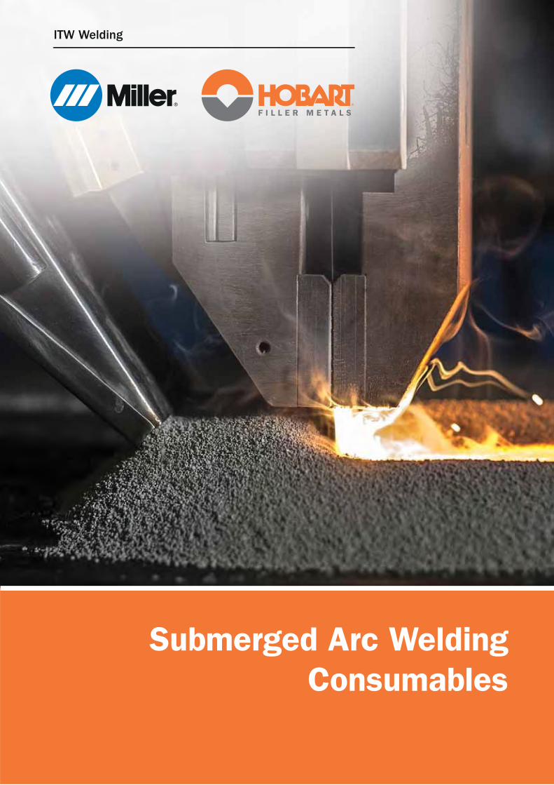
Submerged Arc Welding
Consumables

ITW Welding - Your Route to Full Performance Submerged Arc Welding
At ITW Welding we are passionate about the submerged
arc welding process and this is reflected by our unique
offering to the market. When you use Hobart’s best in class
welding consumables or Miller’s cutting edge equipment,
you will enjoy the most advanced and productive
submerged arc products.
The interaction of two consumables – flux and wire – and the
availability of a variety of process variants make submerged
arc welding a complex arc welding process and fabricators
may not always utilize its full potential.
Partnering with ITW Welding, you will have the deep knowledge
and experience of our engineers at your side, along with fully
equipped laboratories for dedicated application research.
Testing facilities include multi-wire installations to simulate
and develop productive welding procedures for industrial
segments such as longitudinal and spiral pipe mills,
wind tower production, pressure vessel fabrication and
shipbuilding. Often an audit by ITW Welding specialists at
our customers’ facilities precedes a route that leads to full
performance submerged arc welding at lower bottom-line cost.
Our flux manufacturing utilizes the latest technology,
producing high performance SAW fluxes with consistent quality
and supplied in innovative packaging solutions for safe
and cost efficient storage and handling.
ITW Welding is a total solutions provider for the submerged arc
welding process, including welding heads, tractors, column & booms,
flux drying & handling equipment and preheating equipment.
The offer includes engineering and automation and turnkey
solutions, making us the ideal partner for one-stop-shopping.
Contact us and discover ways to implement submerged arc
welding or optimize your existing processes to their full potential.
www.hobartbrothers.com3rd edition2

Disclaimer: The information contained herein is furnished for reference purposes only and is believed to be accurate and reliable. Typical data are those obtained when welding and testing are performed in accordance with prescribed standards and guidelines. Other tests may produce different results and typical data should not be assumed to yield similar results in a particular application or weldment. ITW Welding does not assume responsibility for any results obtained by persons over whose methods it has no control. It is the user’s responsibility to determine the suitability of any products or methods mentioned herein for a particular purpose. In light of the foregoing, ITW Welding specifically disclaims all warranties, express or implied, including warranties of merchantability and fitness for a particular purpose, and further disclaims any liability for consequential or incidental damages of any kind, including lost profits.
Selection tables
Flux selection guide by industrial application . . . . . . . . . . . . . . . . . . . . . . . . . . . . . . . . . . . . 5
Flux selection quick guide . . . . . . . . . . . . . . . . . . . . . . . . . . . . . . . . . . . . . . . . . . . . . . . . . . 6
SubCOR metal cored wire selection quick guide . . . . . . . . . . . . . . . . . . . . . . . . . . . . . . . . . . 7
SubCOR SL cored wire selection quick guide . . . . . . . . . . . . . . . . . . . . . . . . . . . . . . . . . . . . 8
SAW solid wire and strip range . . . . . . . . . . . . . . . . . . . . . . . . . . . . . . . . . . . . . . . . . . . . . . 9
Flux selection by SDX solid wire . . . . . . . . . . . . . . . . . . . . . . . . . . . . . . . . . . . . . . . . . . . . 10
Flux selection by SubCOR cored wire . . . . . . . . . . . . . . . . . . . . . . . . . . . . . . . . . . . . . . . . . 10
Flux selection by AWS wire classification . . . . . . . . . . . . . . . . . . . . . . . . . . . . . . . . . . . . . . 11
Consumables
SWX 110 - EN ISO 14174: S A AB 1 67 AC H5 . . . . . . . . . . . . . . . . . . . . . . . . . . . . . . . . . . 12
SWX 120 - EN ISO 14174: S A AB 1 57 AC H5 . . . . . . . . . . . . . . . . . . . . . . . . . . . . . . . . . . 14
SWX 130 - EN ISO 14174: S A AB 1 67 AC H5 . . . . . . . . . . . . . . . . . . . . . . . . . . . . . . . . . . 16
SWX 135 - EN ISO 14174: S A AB 1 67 AC H5 . . . . . . . . . . . . . . . . . . . . . . . . . . . . . . . . . . 18
SWX 140 - EN ISO 14174: S A FB 1 57 AC H5 . . . . . . . . . . . . . . . . . . . . . . . . . . . . . . . . . . 20
SWX 150 - EN ISO 14174: S A FB 1 55 AC H5 . . . . . . . . . . . . . . . . . . . . . . . . . . . . . . . . . . 22
SWX 220 - EN ISO 14174: S A AF 2 DC . . . . . . . . . . . . . . . . . . . . . . . . . . . . . . . . . . . . . . . 26
SWX 282 - EN ISO 14171: S A AF 2 DC . . . . . . . . . . . . . . . . . . . . . . . . . . . . . . . . . . . . . . . 28
SWX 305 - EN ISO 14174: S A AAS 2B DC . . . . . . . . . . . . . . . . . . . . . . . . . . . . . . . . . . . . . 29
SWX 330 - EN ISO 14174: ES A FB 2B DC . . . . . . . . . . . . . . . . . . . . . . . . . . . . . . . . . . . . . 30
SWX 382 - EN ISO 14174: ES A AF 2B DC . . . . . . . . . . . . . . . . . . . . . . . . . . . . . . . . . . . . . 31
SWX 010 - Powder backing for one-sided welding . . . . . . . . . . . . . . . . . . . . . . . . . . . . . . . . . 32
Approval certficates . . . . . . . . . . . . . . . . . . . . . . . . . . . . . . . . . . . . . . . . . . . . . . . . . . . . . 33
Packaging solutions . . . . . . . . . . . . . . . . . . . . . . . . . . . . . . . . . . . . . . . . . . . . . . . . . . . . . 34
Storage and handling recommendations . . . . . . . . . . . . . . . . . . . . . . . . . . . . . . . . . . . . . . 35
Full performance submerged arc welding pays back . . . . . . . . . . . . . . . . . . . . . . . . . . . . . . 36
Hobart SubCOR cored wires for submerged arc welding . . . . . . . . . . . . . . . . . . . . . . . . . . . . 38
Improved productivity from SubCOR metal-cored wires . . . . . . . . . . . . . . . . . . . . . . . . . . . . 40
Flux cored micro injection . . . . . . . . . . . . . . . . . . . . . . . . . . . . . . . . . . . . . . . . . . . . . . . . . 42
Classification standards . . . . . . . . . . . . . . . . . . . . . . . . . . . . . . . . . . . . . . . . . . . . . . . . . . 44
Submerged arc welding process . . . . . . . . . . . . . . . . . . . . . . . . . . . . . . . . . . . . . . . . . . . . 51
Submerged arc power sources and AC wave balance . . . . . . . . . . . . . . . . . . . . . . . . . . . . . . 60
SAW and ESW strip cladding . . . . . . . . . . . . . . . . . . . . . . . . . . . . . . . . . . . . . . . . . . . . . . . 64
Trouble shooting . . . . . . . . . . . . . . . . . . . . . . . . . . . . . . . . . . . . . . . . . . . . . . . . . . . . . . . 66
NOTE: With this catalogue, ITW Welding introduces its all new, global range of Hobart submerged arc welding
consumables under the new product names SWX for fluxes, SDX for solid wires and SubCOR for cored wires.
Earlier products marketed in individual countries under brand names like Hobart, Elga and Tien Tai remain to
be available until further notice.
Table of Contents
3
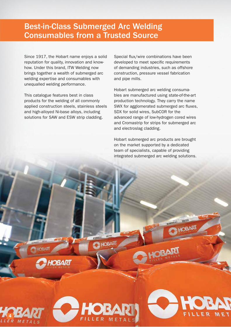
Best-in-Class Submerged Arc Welding Consumables from a Trusted Source
Since 1917, the Hobart name enjoys a solid
reputation for quality, innovation and know-
how. Under this brand, ITW Welding now
brings together a wealth of submerged arc
welding expertise and consumables with
unequalled welding performance.
This catalogue features best in class
products for the welding of all commonly
applied construction steels, stainless steels
and high-alloyed Ni-base alloys, including
solutions for SAW and ESW strip cladding.
Special flux/wire combinations have been
developed to meet specific requirements
of demanding industries, such as offshore
construction, pressure vessel fabrication
and pipe mills.
Hobart submerged arc welding consuma-
bles are manufactured using state-of-the-art
production technology. They carry the name
SWX for agglomerated submerged arc fluxes,
SDX for solid wires, SubCOR for the
advanced range of low-hydrogen cored wires
and Cromastrip for strips for submerged arc
and electroslag cladding.
Hobart submerged arc products are brought
on the market supported by a dedicated
team of specialists, capable of providing
integrated submerged arc welding solutions.
4
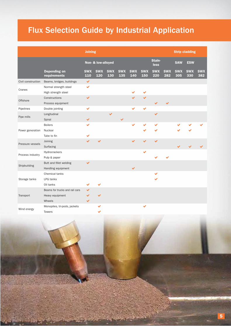
Flux Selection Guide by Industrial Application
Joining Strip cladding
Non- & low-alloyedStain-
lessSAW ESW
Depending on
requirements
SWX
110
SWX
120
SWX
130
SWX
135
SWX
140
SWX
150
SWX
220
SWX
282
SWX
305
SWX
330
SWX
382
Civil construction Beams, bridges, buildings
CranesNormal strength steel
High strength steel
OffshoreConstructions
Process equipment
Pipelines Double jointing
Pipe millsLongitudinal
Spiral
Power generation
Boilers
Nuclear
Tube to fin
Pressure vesselsJoining
Surfacing
Process industryHydrocrackers
Pulp & paper
ShipbuildingButt and fillet welding
Handling equipment
Storage tanks
Chemical tanks
LPG tanks
Oil tanks
Transport
Beams for trucks and rail cars
Heavy equipment
Wheels
Wind energyMonopiles, tri-pods, jackets
Towers
5

Flux Selection Quick Guide
SWX 110 Medium basic general purpose flux allowing high travel speeds
Covers a wide range of applications
Can be used with a range of wires to cover mild steel and medium tensile fine-grained steel with impact toughness
requirements down to -40°C (-40°F)
SWX 120 Suitable for circumferential and longitudinal multi-layer welds
Productive flux with good impact toughness down to -50°C (-58°F), using standard quality S2 and S2Si solid wires
Single- and multi-wire operations
SWX 130 High current carrying capacity
High welding speed and good mechanical properties in two-run welding with up to five wires
Flat and wide bead profile with smooth wetting
SWX 135High welding speed and good mechanical properties in two-run welding with up to three wires
Fast freezing slag
Flat and wide bead profile with smooth wetting
SWX 140Versatile and productive basic flux for applications with increased low-temperature toughness demands down to -50°C (-58°F)
Meets toughness requirements down to -60°C (-76°F) with SubCOR cored wires
Single- and two-run welds, multi-layer welds
Single- and multi-wire set-ups
SWX 150For demanding applications, such as offshore, pressure vessel, cryogenic and nuclear fabrication
Excellent impact toughness down to -60°C (-76°F) + CTOD
Wide range of flux/wire combinations, including for high strength, low-temperature and creep resistant applications
Single- and multi-wire operations
Narrow gap welding
SWX 220Joining of austenitic, duplex and super duplex stainless steels, dissimilar joints and higher alloyed stainless steel grades
Excellent slag detachability in multi-run welds
Suitable for a wide range of stainless steel applications at standard welding speed
SWX 282Joining of Ni-base alloys, such as Alloy 82, Alloy 600 and Alloy 625
Single- or multi-run operation
Excellent impact toughness down to -196°C (-320°F)
SWX 305Submerged arc strip cladding with stainless strips
Austenitic clad layer compositions on mild and low-alloyed steel
Smooth bead appearance and easy slag removal
SWX 330ESW strip cladding flux
Austenitic stainless composition in one layer
High current carrying capacity
SWX 382Electroslag strip cladding with Ni-base strips
Ni-base clad composition in one or two layers
SWX 010Has no influence on weld metal properties
Gives a regular, smooth root pass
6

SubCOR metal cored wire selection quick guide
SubCOR EM12K-S
General purpose cored wire electrode for submerged arc welding of non-alloyed steels
Higher deposition rate than solid wires
Similar in chemistry to AWS A5.17: EM12K
Suitable fluxes: SWX 110, SWX 120, SWX 140 and SWX150
SubCOR EM13K-S
General purpose cored wire electrode for submerged arc welding of non-alloyed steels
Higher deposition rate than solid wires and at the same time improved impact toughness properties
Similar in chemistry to AWS A5.17: EM13K
Suitable fluxes: SWX 110, SWX 120 and SWX150
SubCOR EM13K-S MOD
General purpose cored wire electrode for submerged arc welding of non-alloyed steels with PWHT
Higher deposition rate than solid wires
Similar in chemistry to AWS A5.17: EM13K
Suitable fluxes: SWX 110, SWX 120, SWX 140 and SWX 150
SubCOR 92-S
Low-alloyed cored wire electrode for high strength applications: AWS A5.23 chemistry M1
Designed for tensile strength levels above 550 MPa (80ksi)
Like all SubCOR wires it provides improved depostion rates compared to solid wires
Suitable fluxes: SWX 140 and SWX 150
SubCOR F2-S
Low-alloyed wire for high strength applications: AWS A5.23 chemistry F2
Designed for tensile strength levels over 620 MPa (90 ksi)
Suitable flux: SWX 150
SubCOR 100F3-S
Low-alloyed wire for high strength applications: AWS A5.23 chemistry F3
Designed for tensile strength levels over 690 MPa (100 ksi)
Suitable fluxes: SWX 140 and SWX 150
SubCOR 120-S
Low-alloyed cored wire electrode for high strength applications: AWS A5.23 chemisty M4
Designed for tensile strength levels above 760 MPa (110 ksi)
Like all SubCOR wires it provides improved depostion rates compared to solid wires
Suitable flux: SWX 150
SubCOR N1-S
Low-alloyed cored wire electrode where a 1% nickel deposit is required: AWS A5.23 chemistry Ni1
Designed for tensile strengths above 480 MPa (70 ksi)
Suitable fluxes include SWX 150
SubCOR W-S
Low-alloyed wire for copper alloyed weathering steels
Very good impact properties down to - 50 °C (- 60 °F )
Suitable flux: SWX 150
Cr-Mo alloyed wire for creep resistant steels. Chemistry- AWS A5.23 B2
SubCOR B2-S Like all SubCOR wires it provides improved depostion rates compared to solid wires
Suitable flux: SWX 150
Cr-Mo alloyed wire for creep resistant steels. Chemistry- AWS A5.23 B3
SubCOR B3-S Like all SubCOR wires it provides improved depostion rates compared to solid wires
Suitable flux: SWX 150
7
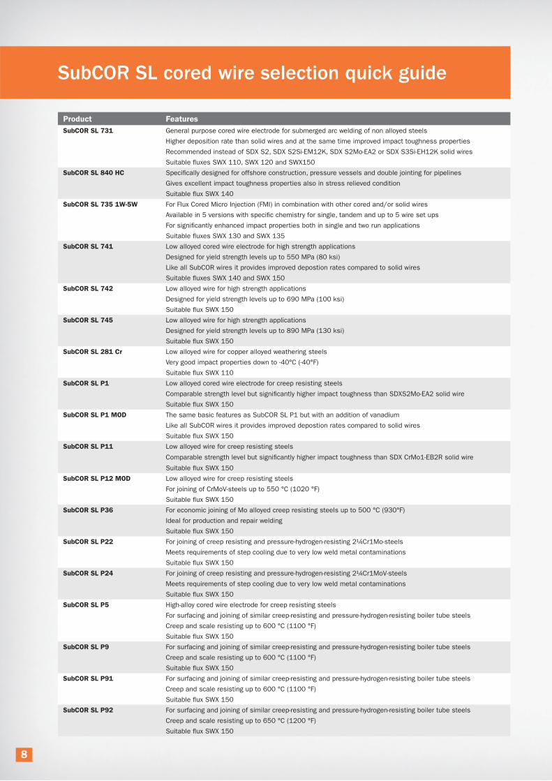
SubCOR SL cored wire selection quick guide
SubCOR SL 731 General purpose cored wire electrode for submerged arc welding of non alloyed steels
Higher deposition rate than solid wires and at the same time improved impact toughness properties
Recommended instead of SDX S2, SDX S2Si-EM12K, SDX S2Mo-EA2 or SDX S3Si-EH12K solid wires
Suitable fluxes SWX 110, SWX 120 and SWX150
SubCOR SL 840 HC Specifically designed for offshore construction, pressure vessels and double jointing for pipelines
Gives excellent impact toughness properties also in stress relieved condition
Suitable flux SWX 140
SubCOR SL 735 1W-5W For Flux Cored Micro Injection (FMI) in combination with other cored and/or solid wires
Available in 5 versions with specific chemistry for single, tandem and up to 5 wire set ups
For significantly enhanced impact properties both in single and two run applications
Suitable fluxes SWX 130 and SWX 135
SubCOR SL 741 Low alloyed cored wire electrode for high strength applications
Designed for yield strength levels up to 550 MPa (80 ksi)
Like all SubCOR wires it provides improved depostion rates compared to solid wires
Suitable fluxes SWX 140 and SWX 150
SubCOR SL 742 Low alloyed wire for high strength applications
Designed for yield strength levels up to 690 MPa (100 ksi)
Suitable flux SWX 150
SubCOR SL 745 Low alloyed wire for high strength applications
Designed for yield strength levels up to 890 MPa (130 ksi)
Suitable flux SWX 150
SubCOR SL 281 Cr Low alloyed wire for copper alloyed weathering steels
Very good impact properties down to -40°C (-40°F)
Suitable flux SWX 110
SubCOR SL P1 Low alloyed cored wire electrode for creep resisting steels
Comparable strength level but significantly higher impact toughness than SDXS2Mo-EA2 solid wire
Suitable flux SWX 150
SubCOR SL P1 MOD The same basic features as SubCOR SL P1 but with an addition of vanadium
Like all SubCOR wires it provides improved depostion rates compared to solid wires
Suitable flux SWX 150
SubCOR SL P11 Low alloyed wire for creep resisting steels
Comparable strength level but significantly higher impact toughness than SDX CrMo1-EB2R solid wire
Suitable flux SWX 150
SubCOR SL P12 MOD Low alloyed wire for creep resisting steels
For joining of CrMoV-steels up to 550 °C (1020 °F)
Suitable flux SWX 150
SubCOR SL P36 For economic joining of Mo alloyed creep resisting steels up to 500 °C (930°F)
Ideal for production and repair welding
Suitable flux SWX 150
SubCOR SL P22 For joining of creep resisting and pressure-hydrogen-resisting 2¼Cr1Mo-steels
Meets requirements of step cooling due to very low weld metal contaminations
Suitable flux SWX 150
SubCOR SL P24 For joining of creep resisting and pressure-hydrogen-resisting 2¼Cr1MoV-steels
Meets requirements of step cooling due to very low weld metal contaminations
Suitable flux SWX 150
SubCOR SL P5 High-alloy cored wire electrode for creep resisting steels
For surfacing and joining of similar creep-resisting and pressure-hydrogen-resisting boiler tube steels
Creep and scale resisting up to 600 °C (1100 °F)
Suitable flux SWX 150
SubCOR SL P9 For surfacing and joining of similar creep-resisting and pressure-hydrogen-resisting boiler tube steels
Creep and scale resisting up to 600 °C (1100 °F)
Suitable flux SWX 150
SubCOR SL P91 For surfacing and joining of similar creep-resisting and pressure-hydrogen-resisting boiler tube steels
Creep and scale resisting up to 600 °C (1100 °F)
Suitable flux SWX 150
SubCOR SL P92 For surfacing and joining of similar creep-resisting and pressure-hydrogen-resisting boiler tube steels
Creep and scale resisting up to 650 °C (1200 °F)
Suitable flux SWX 150
8

Typical chemical composition (%)
Non- & low-alloyed solid wires C Si Mn P S Cr Ni Mo Cu Other
Product name EN ISO AWS
SDX S1-EL12 EN ISO 14171: S1 AWS A5.17: EL12 0.08 0.07 0.49 0.010 0.013 0.05 0.03 0.01 0.06
SDX EM13K AWS A5.17: EM13K 0.08 0.57 1.10 0.011 0.012 0.06 0.03 0.02 0.05
SDX S2 EN ISO 14171: S2 0.10 0.11 0.97 0.010 0.011 0.05 0.05 0.02 0.04
SDX S2Si-EM12K EN ISO 14171: S2Si AWS A5.17: EM12K 0.09 0.22 1.12 0.009 0.011 0.04 0.04 0.01 0.03
SDX S2Mo-EA2 EN ISO 14171: S2Mo AWS A5.23: EA2 0.09 0.12 1.09 0.010 0.012 0.05 0.04 0.50 0.04
SDX S3 EN ISO 14171: S3 0.11 0.12 1.55 0.010 0.009 0.04 0.03 0.01 0.05
SDX S3Si-EH12K EN ISO 14171: S3Si AWS A5.17: EH12K 0.11 0.29 1.69 0.009 0.010 0.05 0.05 0.02 0.06
SDX S3Mo-EA4 EN ISO 14171: S3Mo AWS A5.23: EA4 0.12 0.10 1.45 0.010 0.012 0.04 0.03 0.52 0.05
SDX S4-EH14 EN ISO 14171: S4 AWS A5.17: EH14 0.13 0.07 1.95 0.009 0.010 0.03 0.03 0.01 0.04
SDX CrMo1-EB2R EN ISO 24598: S CrMo1 AWS A5.23: EB2R 0.10 0.15 0.88 0.006 0.004 1.15 0.04 0.55 0.03 X<12
SDX CrMo2-EB3R EN ISO 24598: S CrMo2 AWS A5.23: EB3R 0.11 0.14 0.60 0.004 0.005 2.45 0.05 1.02 0.04 X<12
SDX S2Ni1-ENi1 EN ISO 14171: S2Ni1 AWS A5.23: ENi1 0.09 0.12 0.96 0.09 0.07 0.04 0.97 0.02 0.05
SDX S2Ni2-ENi2 EN ISO 14171: S2Ni2 AWS A5.23: ENi2 0.09 0.15 1.00 0.007 0.006 0.04 2.29 0.02 0.05
SDX S2Ni1Cu EN ISO 14171: S2Ni1Cu 0.10 0.22 0.99 0.010 0.009 0.25 0.79 0.02 0.49
SDX S3Ni1Mo0.2-ENi5 EN ISO 14171: S3Ni1Mo0.2 AWS A5.23: ENi5 0.10 0.21 1.44 0.009 0.009 0.03 0.96 0.21 0.04
SDX S3Ni1Mo-EF3 EN ISO 14171: S3Ni1Mo AWS A5.23: EF3 0.12 0.11 1.72 0.010 0.008 0.03 0.92 0.55 0.05
SDX S3Ni2.5CrMo EN ISO 26304: S3Ni2.5CrMo 0.12 0.15 1.47 0.010 0.011 0.63 2.28 0.53 0.03
SDX S3TiB 0.08 0.27 1.50 0.007 0.006 0.02 0.03 0.01 0.04 Ti 0.16. B 0.012
SDX S3MoTiB 0.07 0.25 1.30 0.009 0.007 0.03 0.03 0.53 0.05 Ti 0.15. B 0.013
Stainless solid wires C Si Mn P S Cr Ni Mo N Other
SDX 308L EN ISO 14343: S 19 9 L AWS A5.9: ER308L 0.02 0.48 1.80 0.012 0.010 20.2 10.3 0.2 0.04
SDX 347 EN ISO 14343: S 19 9 Nb AWS A5.9: ER347 0.03 0.42 1.72 0.013 0.012 19.8 9.8 0.1 0.07 Nb 0.7
SDX 316L EN ISO 14343: S 19 12 3 L AWS A5.9: ER316L 0.01 0.49 1.77 0.015 0.011 18.6 12.2 2.7 0.05
SDX 317L EN ISO 14343: S 19 13 4 L AWS A5.9: ER317L 0.01 0.42 1.78 0.014 0.013 19.0 13.7 3.5 0.05
SDX 309L EN ISO 14343: S 23 12 L AWS A5.9: ER309L 0.01 0.45 1.85 0.016 0.012 23.7 12.9 0.1 0.06
SDX 309LMo EN ISO 14343: S 23 12 2 L 0.01 0.37 1.49 0.016 0.015 23.4 13.2 2.6 0.04
SDX 410NiMo AWS A5.9: ER410NiMo 0.05 0.42 0.51 0.014 0.011 12.1 4.5 0.6 0.05
SDX 2209 EN ISO 14343: S 22 9 3 N L AWS A5.9: ER2209 0.01 0.48 1.50 0.016 0.010 22.9 8.3 3.2 0.15
SDX 2594 EN ISO 14343: S 25 9 4 N L AWS A5.9: ER2594 0.01 0.45 0.44 0.015 0.016 24.9 9.4 3.8 0.26
Nickel base solid wires C Si Mn P S Cr Ni Mo N Other
SDX NiCrMo-3 EN ISO 18274: S Ni6625 AWS A5.14: ERNiCrMo-3 0.06 0.22 0.27 0.014 0.013 21.9 Bal. 9.1 Nb: 3.3 Fe: 1.1
SDX NiCr-3 EN ISO 18274: S Ni6082 AWS A5.14: ERNiCr-3 0.05 0.25 3.10 0.017 0.009 19.80 Bal. 0.13 Nb: 2.8 Fe: 1.0
Stainless strips C Si Mn P S Cr Ni Mo N Other
For SAW
Cromastrip 308L EN ISO 14343: B 19 9 L AWS A5.9: EQ308L 0.01 0.4 1.7 0.014 0.001 20.3 10.3 0.1 0.05
Cromastrip 347 EN ISO 14343: B 19 9 Nb AWS A5.9: EQ347 0.02 0.4 1.7 0.014 0.001 19.7 10.5 0.0 0.05 Nb 0.5
Cromastrip 316L EN ISO 14343: B 19 12 3 L AWS A5.9: EQ316L 0.02 0.4 1.6 0.020 0.001 18.3 12.6 2.8 0.05
Cromastrip 309L EN ISO 14343: B 23 12 L AWS A5.9: EQ309L 0.01 0.4 1.6 0.011 0.001 24.0 13.2 0.1 0.05
Cromastrip 309LNb EN ISO 14343: B 23 12 L Nb 0.02 0.4 2.1 0.014 0.001 23.8 12.5 0.2 0.05 Nb 0.6
For ESW
Cromastrip 21.11 L EN ISO 14343: B 21 11 L 0.02 0.3 1.7 0.014 0.001 21.2 11.2 0.1 0.03
Cromastrip 21.13.3 L 0.01 0.4 1.7 0.017 0.001 20.3 14.3 2.8 0.04
Cromastrip 21.11 LNb EN ISO 14343: B 21 11 L Nb 0.01 0.3 1.7 0.015 0.001 21.3 11.1 0.1 0.05 Nb 0.6
Nickel base strips C Si Mn P S Cr Ni Mo N Other
Cromastrip NiCrMo-3 EN ISO 18274: Ni6625 AWS A5.14: EQNiCrMo-3 0.05 0.1 0.3 0.011 0.002 22.0 Bal. 9.0 0.05 Nb 3.5 Fe 0.4
Cromastrip NiCr-3 EN ISO 18274: Ni6082 AWS A5.14: EQNiCr-3 0.05 0.2 3.0 0.013 0.002 22.0 Bal. 0.1 0.05 Nb 2.5 Fe <1.0
SAW Solid Wire and Strip Range
9
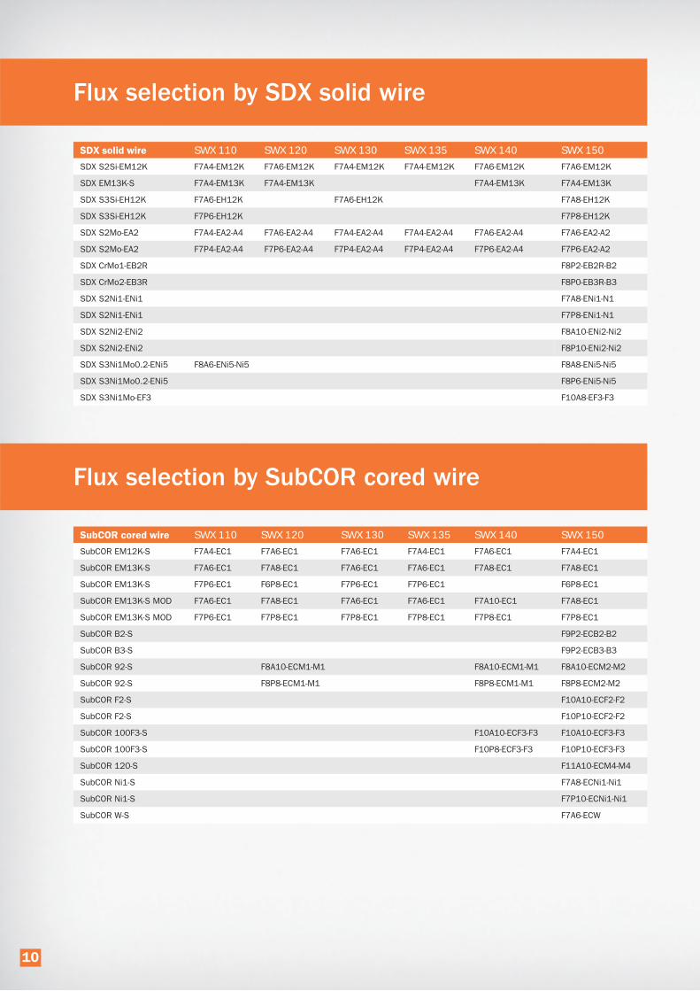
Flux selection by SDX solid wire
SWX 110 SWX 120 SWX 130 SWX 135 SWX 140 SWX 150
SDX S2Si-EM12K F7A4-EM12K F7A6-EM12K F7A4-EM12K F7A4-EM12K F7A6-EM12K F7A6-EM12K
SDX EM13K-S F7A4-EM13K F7A4-EM13K F7A4-EM13K F7A4-EM13K
SDX S3Si-EH12K F7A6-EH12K F7A6-EH12K F7A8-EH12K
SDX S3Si-EH12K F7P6-EH12K F7P8-EH12K
SDX S2Mo-EA2 F7A4-EA2-A4 F7A6-EA2-A4 F7A4-EA2-A4 F7A4-EA2-A4 F7A6-EA2-A4 F7A6-EA2-A2
SDX S2Mo-EA2 F7P4-EA2-A4 F7P6-EA2-A4 F7P4-EA2-A4 F7P4-EA2-A4 F7P6-EA2-A4 F7P6-EA2-A2
SDX CrMo1-EB2R F8P2-EB2R-B2
SDX CrMo2-EB3R F8P0-EB3R-B3
SDX S2Ni1-ENi1 F7A8-ENi1-N1
SDX S2Ni1-ENi1 F7P8-ENi1-N1
SDX S2Ni2-ENi2 F8A10-ENi2-Ni2
SDX S2Ni2-ENi2 F8P10-ENi2-Ni2
SDX S3Ni1Mo0.2-ENi5 F8A6-ENi5-Ni5 F8A8-ENi5-Ni5
SDX S3Ni1Mo0.2-ENi5 F8P6-ENi5-Ni5
SDX S3Ni1Mo-EF3 F10A8-EF3-F3
Flux selection by SubCOR cored wire
SWX 110 SWX 120 SWX 130 SWX 135 SWX 140 SWX 150
SubCOR EM12K-S F7A4-EC1 F7A6-EC1 F7A6-EC1 F7A4-EC1 F7A6-EC1 F7A4-EC1
SubCOR EM13K-S F7A6-EC1 F7A8-EC1 F7A6-EC1 F7A6-EC1 F7A8-EC1 F7A8-EC1
SubCOR EM13K-S F7P6-EC1 F6P8-EC1 F7P6-EC1 F7P6-EC1 F6P8-EC1
SubCOR EM13K-S MOD F7A6-EC1 F7A8-EC1 F7A6-EC1 F7A6-EC1 F7A10-EC1 F7A8-EC1
SubCOR EM13K-S MOD F7P6-EC1 F7P8-EC1 F7P8-EC1 F7P8-EC1 F7P8-EC1 F7P8-EC1
SubCOR B2-S F9P2-ECB2-B2
SubCOR B3-S F9P2-ECB3-B3
SubCOR 92-S F8A10-ECM1-M1 F8A10-ECM1-M1 F8A10-ECM2-M2
SubCOR 92-S F8P8-ECM1-M1 F8P8-ECM1-M1 F8P8-ECM2-M2
SubCOR F2-S F10A10-ECF2-F2
SubCOR F2-S F10P10-ECF2-F2
SubCOR 100F3-S F10A10-ECF3-F3 F10A10-ECF3-F3
SubCOR 100F3-S F10P8-ECF3-F3 F10P10-ECF3-F3
SubCOR 120-S F11A10-ECM4-M4
SubCOR Ni1-S F7A8-ECNi1-Ni1
SubCOR Ni1-S F7P10-ECNi1-Ni1
SubCOR W-S F7A6-ECW
10
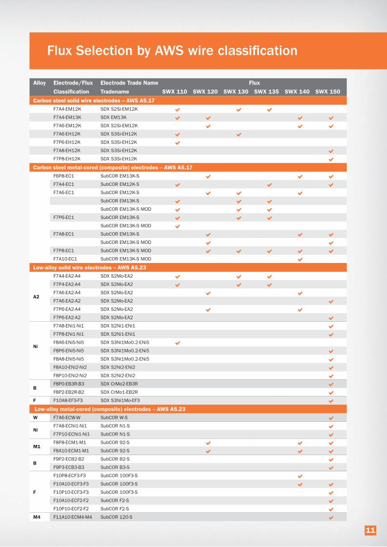
Flux Selection by AWS wire classification
Alloy Electrode/Flux Electrode Trade Name Flux
Classification Tradename SWX 110 SWX 120 SWX 130 SWX 135 SWX 140 SWX 150
F7A4-EM12K SDX S2Si-EM12K
F7A4-EM13K SDX EM13K
F7A6-EM12K SDX S2Si-EM12K
F7A6-EH12K SDX S3Si-EH12K
F7P6-EH12K SDX S3Si-EH12K
F7A8-EH12K SDX S3Si-EH12K
F7P8-EH12K SDX S3Si-EH12K
F6P8-EC1 SubCOR EM13K-S
F7A4-EC1 SubCOR EM12K-S
F7A6-EC1 SubCOR EM12K-S
SubCOR EM13K-S
SubCOR EM13K-S MOD
F7P6-EC1 SubCOR EM13K-S
SubCOR EM13K-S MOD
F7A8-EC1 SubCOR EM13K-S
SubCOR EM13K-S MOD
F7P8-EC1 SubCOR EM13K-S MOD
F7A10-EC1 SubCOR EM13K-S MOD
A2
F7A4-EA2-A4 SDX S2Mo-EA2
F7P4-EA2-A4 SDX S2Mo-EA2
F7A6-EA2-A4 SDX S2Mo-EA2
F7A6-EA2-A2 SDX S2Mo-EA2
F7P6-EA2-A4 SDX S2Mo-EA2
F7P6-EA2-A2 SDX S2Mo-EA2
Ni
F7A8-ENi1-Ni1 SDX S2Ni1-ENi1
F7P8-ENi1-Ni1 SDX S2Ni1-ENi1
F8A6-ENi5-Ni5 SDX S3Ni1Mo0.2-ENi5
F8P6-ENi5-Ni5 SDX S3Ni1Mo0.2-ENi5
F8A8-ENi5-Ni5 SDX S3Ni1Mo0.2-ENi5
F8A10-ENi2-Ni2 SDX S2Ni2-ENi2
F8P10-ENi2-Ni2 SDX S2Ni2-ENi2
BF8P0-EB3R-B3 SDX CrMo2-EB3R
F8P2-EB2R-B2 SDX CrMo1-EB2R
F F10A8-EF3-F3 SDX S3Ni1Mo-EF3
W F7A6-ECW-W SubCOR W-S
NiF7A8-ECNi1-Ni1 SubCOR N1-S
F7P10-ECNi1-Ni1 SubCOR N1-S
M1F8P8-ECM1-M1 SubCOR 92-S
F8A10-ECM1-M1 SubCOR 92-S
BF9P2-ECB2-B2 SubCOR B2-S
F9P3-ECB3-B3 SubCOR B3-S
F
F10P8-ECF3-F3 SubCOR 100F3-S
F10A10-ECF3-F3 SubCOR 100F3-S
F10P10-ECF3-F3 SubCOR 100F3-S
F10A10-ECF2-F2 SubCOR F2-S
F10P10-ECF2-F2 SubCOR F2-S
M4 F11A10-ECM4-M4 SubCOR 120-S
11

DescriptionHobart SWX 110 is a versatile and universally
applied agglomerated welding flux. It has a care-
fully chosen aluminate-basic formulation - with a
basicity between neutral and basic - providing a
set of welding characteristics that makes the flux
suited for a wide range of submerged arc welding
applications in a variety of industries. It combines
high travel speeds and excellent slag detachability
with good low-temperature impact toughness down
to -40°C (-40ºF). Suited for single- and multi-run
welding with smooth weld bead appearance and
self detaching slag. It has a wide parameter box
and performs equally well in single-wire, twin- and
tandem welding, making it the perfect choice for
productive welding of heavy sections. All of this
makes SWX 110 an excellent multi-application flux
on the shop floor. SWX 110 can be used with
a range of wires to cover mild steel and me-
dium tensile fine-grained steel. SWX 110
is applied in general construction, machine
and heavy equipment building, pressure ves-
sel fabrication, shipbuilding and water and
sewage pipes. Typical shipbuilding applications are
the single- or double-sided welding of ship panels.
Use of the flux in combination with Hobart cored
wires offers further opportunities to improve weld
metal quality, making use of unique cored wire
properties. The flux is delivered in Hobart humidity
proof packaging - EAE bag or DoubleBag - eliminat-
ing the need to re-dry the flux.
• General construction
• Double jointing
• Heavy equipment
• Bridge building
• Shipbuilding
• Pressure vessels
• Heavy beams •
• Tank building
• Water and sewage pipes
Flux /wire combinations for the submerged arc welding of non-and low-alloyed steels
SWX 110 EN ISO 14174: S A AB 1 67 AC H5
Flux type Aluminate-Basic
Basicity index 1.4 (Boniszewski)
Alloy transfer Slightly Si and Mn alloying
Density 1.2 kg/litre
Grain size 0.2-1.6 mm /12-65 mesh
HDM < 5 ml/100 g weld metal
Current DC+/AC
Re-drying unopened bag Not required
Re-drying opened bag See storage and handling recommendations
1.2
1.0
0.8
0.6
0.4
0.2
0.0
Metallurgical behaviour
The diagrams show the typical weld metal analysis
in relation to wire analysis for silicon and manganese.
Single wire, ø 4.0 mm (5/32”), DC+, 30 V, 60 cm/min (24”/min)
0.00 0.05 0.10 0.15 0.20 0.25 0.30
2.4
2.0
1.6
1.2
0.8
0.4
0.0 0.0 0.5 1.0 1.5 2.0
500 A
800 A
% Si in wire
% Mn in wire
% Si in weld metal
500 A
800 A
% Mn in weld metal
AL2 3 2 2 2
~ 35% ~ 25% ~ 20% ~ 15%
With wire EN ISO AWS Re/Rp0.2MPa
RmMPa
A%
CVNJ
YS TS E CVN
ksi ksi % ft-lbf
0°C -20°C -30°C -40°C -46°C 0°F -20°F -40°F -60°F -80°F -100°F
SDX EM13K AW A5.17: F7A4-EM13K 75 87 28 22
SDX S2 AW 14171-A: S 38 4 AB S2 420 500 26 130 110 65
SDX S2Si-EM12K AW 14171-A: S 38 4 AB S2Si A5.17: F7A4-EM12K 420 500 26 130 100 60 71 83 29 48 35
SDX S3Si-EH12K* AW 14171-A: S 42 4 AB S3Si A5.17: F7A6-EH12K 450 560 28 110 65 50 76 88 27 54 38
SR1 A5.17: F7P6-EH12K 440 550 28 100 55 40 67 83 28 58 29
SDX S2Mo-EA2 AW 14171-A: S 46 2 AB S2Mo A5.23: F7A4-EA2-A4 510 590 24 90 70 50 80 90 26 58 33
SR1 A5.23: F7P4-EA2-A4 470 560 24 70 40 74 86 27 49 33
TR 14171-A: S 4T 2 AB S2Mo 50
SDX S3Ni1Mo0.2-ENi5 AW 14171-A: S 50 4 AB S3Ni1Mo0.2 A5.23: F8A6-ENi5-Ni5 570 640 24 90 75 65 40 88 97 25 63 37
SDX S2Ni1Cu AW 14171-A: S 46 3 AB S2Ni1Cu 485 570 26 70 55
SubCOR EM12K-S AW A5.17: F7A4-EC1 60 71 30 45
SubCOR EM13K-S AW A5.17: F7A6-EC1 64 73 28 97 75
SR1 A5.17: F7P6-EC1 64 77 32 264 127
SubCOR EM13K-S MOD AW A5.17: F7A6-EC1 76 84 29 115 50
SR1 A5.17: F7P6-EC1 68 80 31 143 105
SubCOR SL 731 AW 14171-A: S 46 4 AB T3 490 600 29 150 115
SR1 490 600 29 150 115
SubCOR SL 281 Cr AW 14171-A: S 46 4 AB TZ 490 590 25 100 80
AW: as welded, all weld metal. SR: stress relieved, all weld metal. TR: two-run. SR1 : PWHT 1150°F (620°C)/1 h.
* Use with precaution. In certain applications, the manganese content may reach critical levels, leading to hot cracking.
12

Flux/wire combinations for the submerged arc welding of non-and low-alloyed steels
SWX 110 (continued) EN ISO 14174: S A AB 1 67 AC H5
Materials to be welded
Rel ≤ 355 MPa S235JR, S275JR, A106 Gr. B, A333 Gr. 6, P235GH, S275JO, P295GH -20°C SDX S2
-40°C SDX S2, SDX S2Si-EM12K
Rel ≥ 355 MPa S420N, S460ML, P420ML2, S420MCD, S420G2+M, X60, L450 -20°C SDX S2Mo-EA2
-40°C SDX S2, SDX S2Si-EM12K,
TS > 58 ksi A36, A709 Gr. 36, -40°F SubCOR EM12K-S
-100°F SubCOR EM13K-S, SubCOR EM13K-S MOD
TS > 65 ksi A572 Gr.50, A709 Gr. 50, A709 Gr. 50S, A992 -40°F SubCOR EM12K-S
-100°F SubCOR EM13K-S, SubCOR EM13K-S MOD
TS > 70 ksi A588, A516 Gr.70 -40°F SubCOR EM12K-S
-100°F SubCOR EM13K-S, SubCOR EM13K-S MOD
Rel ≥ 420 MPa S420N, S460ML, P420ML2, S420MCD, S420G2+M, X60, L450 -20°C SDX S2Mo-EA2, SDX S2Mo-EA2
-40°C SDX S3Si-EH12K, SubCOR SL 731
Rel ≥ 460 MPa S460M, S460ML, S460ML2, S460MCD, S460G2+M, X65, L450 -20°C SDX S2Mo-EA2
-40°C SubCOR SL 731
Rel ≥ 500 MPa S500QL, S500QL1, P500QL1, P500QL2, X70, S500G2+M -40°C SDX S3Ni1Mo0.2-ENi5
A to D, AH36 to EH36 -20°C SDX S2Mo-EA2
-40°C SDX S2, SDX S2Si-EM12K
SDX S3Si-EH12K, SubCOR SL 731
Rel ≤ 355 S235JOW, S355J2WP, S355J2G2W, COR-TEN, A242-type1, A588 -20°C SDX S2Ni1Cu, SubCOR SL 281 Cr
TÜV
SDX S2
SDX S2Si-EM12K F49A4-EM12K*
SDX S2Mo-EA2 F8A6-EA2-A4*
SDX S3Si-EH12K F49A6-EH12K*
SubCOR EM13K-S Mod F49A6-EC1*
SubCOR SL 731
SubCOR SL 281 Cr
For the complete approval list please see Product Data Sheet
or contact the ITW Welding sales office. * Pending
Flux SWX 110 - Chemical composition all weld metal, typical values
%Si %Mo
SDX EM13K 0.06 0.3 1.2
SDX S2 0.06 0.3 1.2
SDX S2Si-EM12K 0.06 0.5 1.3
SDX S3Si-EH12K 0.07 0.5 1.9
SDX S3Ni1Mo0.2 0.09 0.25 1.4 0.2 0.9
SDX S2Ni1Cu 0.08 0.4 1.3 0.7 0.5
SDX S2Mo-EA2 0.06 0.3 1.3 0.5
SubCOR EM12K-S 0.05 0.2 1.2
SubCOR EM13K-S 0.06 0.3 1.2
SubCOR EM13K-S MOD 0.07 0.4 1.3
SubCOR SL 731 0.05 0.3 1.5
SubCOR SL 281 Cr 0.12 0.6 1.3 0.6 0.5 0.5
Aluminium/PE Bag EAE* 25 55
DoubleBag 1000 2200
*EAE Excess Air Evacuation
13

DescriptionHobart SWX 120 is specifically designed for the
wind tower manufacturing industry where high
integrity longitudinal and circumferential welds
are the challenge and productive welding a
prerequisite. The formulation of this aluminate-
basic flux has been adapted towards a higher
basicity while maintaining the good welding
characteristics of a lower basicity flux. The result
is a “production” flux that yields remarkably good
low-temperature impact toughness down to -50°C
(-58ºF), using SDX S2 or SDX S2Si-EM12K welding
wires. This flux guarantees uniform chemistry and
mechanical properties throughout the heavy,
multi-layer welds that are familiar to this industry.
SWX 120 has a high current carrying capacity and
allows high travel speeds. The slag is easily removed
from the first layers in commonly applied narrow
Y-joints and self-detaching in subsequent filler and
capping layers. Very well suited for single, twin,
tandem and tandem-twin wire welding offering
higher welding productivity and increased efficiency.
Other industries with similar requirements, such as
pressure vessel fabrication and general construction,
will benefit equally well from this outstanding
welding flux. Use of the flux in combination with
Hobart cored wires offers further opportunities to
improve weld metal quality, making use of unique
cored wire properties.
The flux is delivered in Hobart humidity proof pack-
aging - EAE bag or DoubleBag - eliminating the
need to re-dry the flux.
• Wind towers
• Pressure vessels
• General construction
• Tank building
Flux/wire combinations for the submerged arc welding of non-and low-alloyed steels
SWX 120 EN ISO 14174: S A AB 1 57 AC H5
Flux type Aluminate-Basic
Basicity index 1.9 (Boniszewski)
Alloy transfer Slightly Mn alloying
Density ~1.2 kg/litre
Grain size 0.2-1.6 mm /12-65 mesh
HDM < 5 ml/100 g weld metal
Current DC+/AC
Re-drying unopened bag Not required
Re-drying opened bag See storage and handling recommendations
AL2 3 2 2 2
~ 35% ~ 25% ~ 20% ~ 20%
1.0
0.8
0.6
0.4
0.2
0.0
Metallurgical behaviour
The diagrams show the typical weld metal analysis
in relation to wire analysis for silicon and manganese.
Single wire, ø 4.0 mm (5/32”), DC+, 30 V, 60 cm/min (24”/min)
0.00 0.05 0.10 0.15 0.20 0.25 0.30
2.8
2.4
2.0
1.6
1.2
0.8
0.4 0.0 0.5 1.0 1.5 2.0
500 A
800 A
% Si in wire
% Mn in wire
% Si in weld metal
500 A
800 A
% Mn in weld metal
With wire EN ISO AWS Re/Rp0.2MPa
RmMPa
A%
CVNJ
YS TS E CVN
ksi ksi % ft-lbf
-20°C -40°C -50°C -60°C 0°F -20°F -40°F -60°F -80°F -100°F
SDX EM13K AW A5.17: F7A4-EM13K 77 87 29 40
SDX S2 AW 14171-A: S 38 5 AB S2 420 500 26 120 95 70 45
SDX S2Si-EM12K AW 14171-A: S 38 5 AB S2Si A5.17: F7A6-EM12K 430 510 26 130 100 75 45 66 78 27 76 68
SDX S2Mo-EA2 AW 14171-A: S 46 4 AB S2Mo A5.23: F7A6-EA2-A4 500 590 24 90 60 73 83 25 69
SR1 A5.23: F7P6-EA2-A4 490 575 24 90 60 45 68 91 29 44 30
TR 14171-A: S 4T 3 AB S2Mo 65 40
SDX S3Si-EH12K* AW 14171-A: S 46 4 AB S3Si 490 580 27 120 80 50
SR1 480 570 27 110 70 45
TR 14171-A: S 3T 2 AB S3Si 55 30 29
SubCOR EM12K-S AW A5.17: F7A6-EC1 60 70 32 110
SubCOR EM13K-S AW A5.17: F7A8-EC1 58 71 29 105
SR1 A5.17: F6P8-EC1 51 66 34 143 142
SubCOR EM13K-S MOD AW A5.17: F7A10-EC1 72 82 29 161 105
SR1 A5.17: F7P8-EC1 67 80 29 221 134
SubCOR 92-S AW A5.23: F8A10-ECM1-M1 79 93 26 85 52
SR2 A5.23: F8P8-ECM1-M1 71 84 27 103 77
SubCOR SL 731** AW 14171-A: S 46 4 AB T3 A5.23: F8A4-ECG 500 600 27 145 125 54 111 121 22 55 48
SR1 480 580 26 140 120 50
AW: as welded, all weld metal. SR: stress relieved, all weld metal. TR: two-run. * Use with precaution. In certain applications, the manganese content may reach critical levels, leading to hot cracking.
SR1: 1150ºF (620ºC) / 1 h. SR2: 1135ºF (605ºC) / 1 h.** Depends on the type of solid wire used
14

Flux/wire combinations for the submerged arc welding of non-and low-alloyed steels
SWX 120 (continued) EN ISO 14174: S A AB 1 57 AC H5
Materials to be welded
Rel ≤ 355 MPa S235JR, A106 Gr. B, A333 Gr. 6,P235GH, S275JO, S275JR, P295GH -30°C SDX S2Mo-EA2
-50°C SDX S2, SDX S2Si-EM12K
Rel ≥ 355 MPa S355J2, S355N, P355NL1, L360, S355MCD, S355ML, P355GH -20°C SDX S3Si-EH12K
-30°C SDX S2Mo-EA2
-50°C SDX S2, SDX S2Si-EM12K
TS > 58 ksi A36, A709 Gr. 36 -60°F SubCOR EM12K-S
-80°F SubCOR EM13K-S
-100°F SubCOR EM13K-S MOD
TS > 65 ksi A572 Gr. 50, A709 Gr. 50, A709 Gr. 50S, A992 -60°F SubCOR EM12K-S
-80°F SubCOR EM13K-S
-100°F SubCOR EM13K-S MOD
Rel ≥ 420 MPa S420N, S460ML, P420ML2, S420MCD, S420G2+M, L450 -30°C SDX S2Mo-EA2
-40°C SDX S3Si-EH12, SubCOR SL 731
Rel ≥ 460 MPa S460M, S460ML, S460ML2, S460MCD, S460G2+M, L450 -30°C SDX S2Mo-EA2
-40°C SDX S3Si-EH12, SubCOR SL 731
TS > 70 ksi A588, A516 Gr. 70 -60°F SubCOR EM12K-S
-80°F SubCOR EM13K-S
-100°F SubCOR EM13K-S MOD
0.5% Mo P295GH, P355GH, 16Mo3, 17Mo3, 14Mo6 -30°C SDX S2Mo-EA1
TÜV
SDX-EM13K
SDX S2
SDX S2Si-EM12K F49A4-EM12K*
SDX S2Mo-EA2 F8A6-EA2-A4*
SDX S3Si-EH12K F49A6-EH12K*
SubCOR EM13K-S MOD F49A6-EC1
For the complete approval list please see Product Data Sheet or
contact the ITW Welding sales office. *Pending
Flux SWX 120 - Chemical composition all weld metal, typical values
%Si %Mo
SDX-EM13K 0.05 0.2 1.2
SDX S2 0.07 0.2 1.4
SDX S2Si-EM12K 0.07 0.3 1.4
SDX S2Mo-EA2 0.07 0.2 1.4 0.5
SDX S3Si-EH12K 0.10 0.2 2.0
SubCOR EM12K-S 0.05 0.2 1.2
SubCOR EM13K-S 0.05 0.2 1.2
SubCOR EM13K-S MOD 0.08 0.3 1.2
SubCOR 92-S 0.08 0.2 1.3 1.6 0.2
SubCOR SL 731 0.06 0.5 2.1
Aluminium/PE Bag EAE* 25 55
DoubleBag 1000 2200
*EAE Excess Air Evacuation
15

DescriptionHOBART SWX 130 is the welding flux that answers
the call from longitudinal pipe mill manufacturers
for increased welding speed and good mechanical
properties in two-run welding. Thanks to its high
current carrying capacity, it is very well suited for
multi-wire welding with up to five wires. At high
welding speeds, it produces the desired flat and
wide bead profile with absence of peaks, which
provides savings in pipe coating operations.
Slag is self-detaching. With the right combination
of wires, steel grades up to X100 can be welded
with matching mechanical properties. The flux is
delivered in Hobart humidity proof packaging - EAE
bag or DoubleBag - eliminating the need to re-dry
the flux.
• Longitudinal pipe mills
Flux/wire combinations for the submerged arc welding of non-and low-alloyed steels
SWX 130 EN ISO 14174: S A AB 1 67 AC H5
Flux type Aluminate-Basic
Basicity index 1.5 (Boniszewski)
Alloy transfer Slightly Si and Mn alloying
Density 1.2 kg/litre
Grain size 0.2-2.0 mm /10-65 mesh
HDM < 5 ml/100 g weld metal
Current DC+/AC
Re-drying unopened bag Not required
Re-drying opened bag See storage and handling recommendations
0.6
0.5
0.4
0.3
0.2
0.1
0.0
Metallurgical behaviour
The diagrams show the typical weld metal analysis
in relation to wire analysis for silicon and manganese.
Single wire, ø 4.0 mm (5/32”), DC+, 30 V, 60 cm/min (24”/min)
0.00 0.05 0.10 0.15 0.20 0.25 0.30
2.4
2.0
1.6
1.2
0.8
0.4
0.0 0.0 0.5 1.0 1.5 2.0
500 A
800 A
% Si in wire
% Mn in wire
% Si in weld metal
500 A
800 A
% Mn in weld metal
AL2 3 2 2 2
~ 30% ~ 25% ~ 20% ~ 15%
With wire EN ISO AWS Re/Rp0.2MPa
RmMPa
A%
CVNJ
YS TS E CVN
ksi ksi % ft-lbf
0°C -20°C -30°C -40°C -50°C 0°F -20°F -40°F -60°F -80°F -100°F
SDX S2 AW 14171-A: S 38 4 AB S2 430 520 27 110 75 60
SDX S2Si-EM12K AW 14171-A: S 38 4 AB S2Si A5.17: F7A4-EM12K 430 520 27 100 70 50 69 82 27 23
SDX S3Si-EH12K AW 14171-A: S 46 6 AB S3Si A5.17: F7A6-EH12K 490 550 29 81 91 27 46
SDX S2Mo-EA2 AW 14171-A: S 46 2 AB S2Mo A5.23: F7A4-EA2-A4 520 590 24 100 70 40 80 90 27 39
SDX S2Mo-EA2 SR1 A5.23: F7P4-EA2-A4 76 88 28 32
SDX S3Mo-EA4 AW 14171-A: S 50 2 AB S3Mo 580 670 23 55 40
SubCOR EM12K-S AW A5.17: F7A6-EC1 60 71 29 84
SubCOR EM13K-S AW A5.17: F7A6-EC1 65 77 31 70 53
SR1 A5.17: F7P6-EC1 58 72 33 84 69
SubCOR EM13K-S MOD AW A5.17: F7A6-EC1 77 87 27 50
SR1 A5.17: F7P8-EC1 68 83 29 102 47
Mechanical properties of two-run pipe joint (high dilution)
SDX S2Mo-EA2 TR 480 550 23 100 80 50
SDX S3Mo-EA4 TR 510 590 20 70
SDX S3TiB TR 560 700 20 45
SDX S3MoTiB TR 630 700 25 200 180 120
SubCOR SL 735-1W-5W* TR 480 600 24 60 50
Mechanical properties of pipe welds in the two run technique depend on the chemical composition of the base material. AW: As welded, all weld metal. TR: Two Run
* Depends on the type of solid wire used. SR1: PWHT 1150°F (620ºC)/1 h.
16

SDX S2Mo-EA2
For the complete approval list please see Product Data Sheet or
contact the ITW Welding sales office
Flux/wire combinations for the submerged arc welding of non-and low-alloyed steels
SWX 130 (continued) EN ISO 14174: S A AB 1 67 AC H5
Materials to be welded
Rel ≤ 355 MPa X42, X46, L235, L265, L295, L320 -40°C SDX S2Mo-EA2
-50°C SDX S3MoTiB
Rel ≥ 355 MPa X52, L355, L360, L385L, 390, L415 -40°C SDX S2Mo-EA2
-50°C SDX S3MoTiB
TS > 58 ksi A36, A709 Gr. 36, -60°F SubCOR EM12K-S
-80°F SubCOR EM13K-S, SubCOR EM13K-S MOD
TS > 65 ksi A572 Gr. 50, A709 Gr. 50, A709 Gr. 50S, A992 -60°F SubCOR EM12K-S
-80°F SubCOR EM13K-S, SubCOR EM13K-S MOD
Rel ≥ 420 MPa X56, X60, L445, L450 -40°C SDX S2Mo-EA2
-50°C SDX S3MoTiB
Rel ≥ 460 MPa X65, X70, X80 -20°C SDX S3Mo-EA4, SubCOR SL 735-1W-5W
-40°C SDX S3TiB
-50°C SDX S3MoTiB
TS > 70 ksi A588, A516 Gr. 70 -60°F SubCOR EM12K-S
-80°F SubCOR EM13K-S, SubCOR EM13K-S MOD
Flux SWX 130 - Chemical composition all weld metal, typical values
%Si %Mo %Ti
SDX S2 0.06 0.2 1.3
SDX S2Si-EM12K 0.06 0.3 1.3
SDX S3Si-EH12K 0.08 0.3 1.6
SDX S2Mo-EA2 0.05 0.4 1.4 0.5
SDX S3Mo-EA4 0.08 0.4 1.6 0.5
SubCOR EM12K-S 0.05 0.2 1.2
SubCOR EM13K-S 0.06 0.4 1.2
SubCOR EM13K-S MOD 0.06 0.4 1.1
SDX S3TiB 0.06 0.5 1.6 0.024 0.0024
SDX S3MoTiB 0.06 0.5 1.4 0.3 0.022 0.0024
SubCOR SL 735-1W-5W Depends on the type of solid wire used.
Aluminium/PE Bag EAE* 25 55
DoubleBag 1000 2200
*EAE Excess Air Evacuation
17

DescriptionHobart SWX 135 is an aluminate-basic flux spe-
cifically developed for spiral pipe mills. The flux is
suited for two-run applications and can be used
with systems with up to 3 wires. It gives flat welds
with smooth wetting and absence of so called
china hats. This weld appearance is cost saving in
later coating operations.
It has a good current carrying capacity. Slag is self-
detaching. The flux is delivered in Hobart humidity
proof packaging - EAE bag or DoubleBag - eliminat-
ing the need to re-dry the flux.
• Spiral pipe mills
Flux/wire combinations for the submerged arc welding of non-and low-alloyed steels
SWX 135 EN ISO 14174: S A AB 1 67 AC H5
Flux type Aluminate-Basic
Basicity index 1.3 (Boniszewski)
Alloy transfer Slightly Si and Mn alloying
Density 1.2 kg/litre
Grain size 0.2-2.0 mm /10-65 mesh
HDM < 5 ml/100 g weld metal
Current DC+/AC
Re-drying unopened bag Not required
Re-drying opened bag See storage and handling recommendations
Metallurgical behaviour
The diagrams show the typical weld metal analysis
in relation to wire analysis for silicon and manganese.
Single wire, ø 4.0 mm (5/32”), DC+, 30 V, 60 cm/min (24”/min)
AL2 3 2 2 2
~ 35% ~ 20% ~ 25% ~ 15%
1.0
0.8
0.6
0.4
0.2
0.00.00 0.05 0.10 0.15 0.20 0.25 0.30
2.4
2.0
1.6
1.2
0.8
0.4
0.0 0.0 0.5 1.0 1.5 2.0
500 A
800 A
% Si in wire
% Mn in wire
% Si in weld metal500 A
800 A
% Mn in weld metal
With wire EN ISO AWS Re/Rp0.2MPa
RmMPa
A%
CVNJ
YS TS E CVN
ksi ksi % ft-lbf
0°C -40°C -50°C 0°F -20°F -40°F -60°F -80°F -100°F
SDX S2 AW 14171-A: S 38 4 AB S2 430 520 27 110 75 40
SDX S2Si-EM12K AW 14171-A: S 38 4 AB S2 A5.17: F7A4-EM12K 410 500 27 150 90 55 65 78 26 42
SDX S2Mo-EA2 AW 14171-A: S 46 2 AB S2Mo A5.23: F7A4-EA2-A4 510 590 23 90 45 30 71 83 24 43
SDX S2Mo-EA2 SR1 A5.23: F7P4-EA2-A4 64 79 28 23
SDX S3Mo-EA4 AW 14171-A: S 50 2 AB S3Mo 570 670 23 70 50
SubCOR EM12K-S AW A5.17: F7A4-EC1 58 71 29 74
SubCOR EM13K-S AW A5.17: F7A6-EC1 59 71 28 93
SR1 A5.17: F7P6-EC1 51 66 34 50
SubCOR EM13K-S MOD AW A5.17: F7A6-EC1 70 81 28 92 56
SR1 A5.17: F7P8-EC1 62 77 30 94 65
Mechanical properties of two-run pipe joint (high dilution)
SDX S2Mo-EA2 TR 480 560 23 60 35
SDX S3Mo-EA4 TR 520 600 22 60 35
SDX S3TiB TR 560 700 20 120 80 60
SDX S3MoTiB TR 630 700 25 200 180 120
SubCOR SL 735-1W-5W* TR 500 580 24 150 100
Mechanical properties of pipe welds in the two run technique depend on the chemical composition of the base material. AW: As welded, all weld metal. TR: Two Run
* Depends on the type of solid wire used. SR1: PWHT 1150°F (620ºC)/1 h.
18

Flux/wire combinations for the submerged arc welding of non-and low-alloyed steels
SWX 135 (continued) EN ISO 14174: S A AB 1 67 AC H5
Materials to be welded
Rel ≤ 355 MPa X42, X46, L235, L265, L295, L320 -40°C SDX S2, SDX S2Si-EM12K
Rel ≥ 355 MPa X52, L355, L360, L385L, 390, L415 -40°C SDX S2, SDX S2Si-EM12K
TS > 58 ksi A36, A709 Gr. 36, -40°F SubCOR EM12K-S
-80°F SubCOR EM13K-S, SubCOR EM13K-S MOD
TS > 65 ksi A572 Gr. 50, A709 Gr. 50, A709 Gr. 50S, A992 -40°F SubCOR EM12K-S
-80°F SubCOR EM13K-S, SubCOR EM13K-S MOD
Rel ≥ 420 MPa X56, X60, L445, L450 -20°C SDX S2Mo-EA2
-40°C SDX S3TiB
-50°C SDX S3MoTiB
Rel ≥ 460 MPa X65, X70, X80 -20°C S2Mo-EA2
-40°C SDX S3TiB, SubCOR SL 735-1W-5W
-50°C SDX S3MoTiB
TS > 70ksi A588, A516 Gr. 70 -40°F SubCOR EM12K-S
-80°F SubCOR EM13K-S, SubCOR EM13K-S MOD
Flux SWX 135 - Chemical composition all weld metal, typical values
%Si %Mo %Ti
SDX S2 0.05 0.3 1.3
SDX S2Si-EM12K 0.06 0.5 1.4
SDX S2Mo-EA2 0.06 0.3 1.4 0.5
SDX S3Mo-EA4 0.06 0.3 1.5 0.5
SubCOR EM12K-S 0.06 0.3 1.2
SubCOR EM13K-S 0.05 0.5 1.2
SubCOR EM13K-S MOD 0.06 0.3 1.3
SDX S3TiB 0.06 0.5 1.6 0.024 0.0024
SDX S3MoTiB 0.06 0.5 1.4 0.3 0.022 0.0024
SubCOR SL 735-1W-5W Depends on the type of solid wire used.
SDX S2
SDX S2Si-EM12K
SDX S2Mo-EA2
For the complete approval list please see Product Data Sheet or
contact the ITW Welding sales office
Aluminium/PE Bag EAE* 25 55
DoubleBag 1000 2200
*EAE Excess Air Evacuation
19
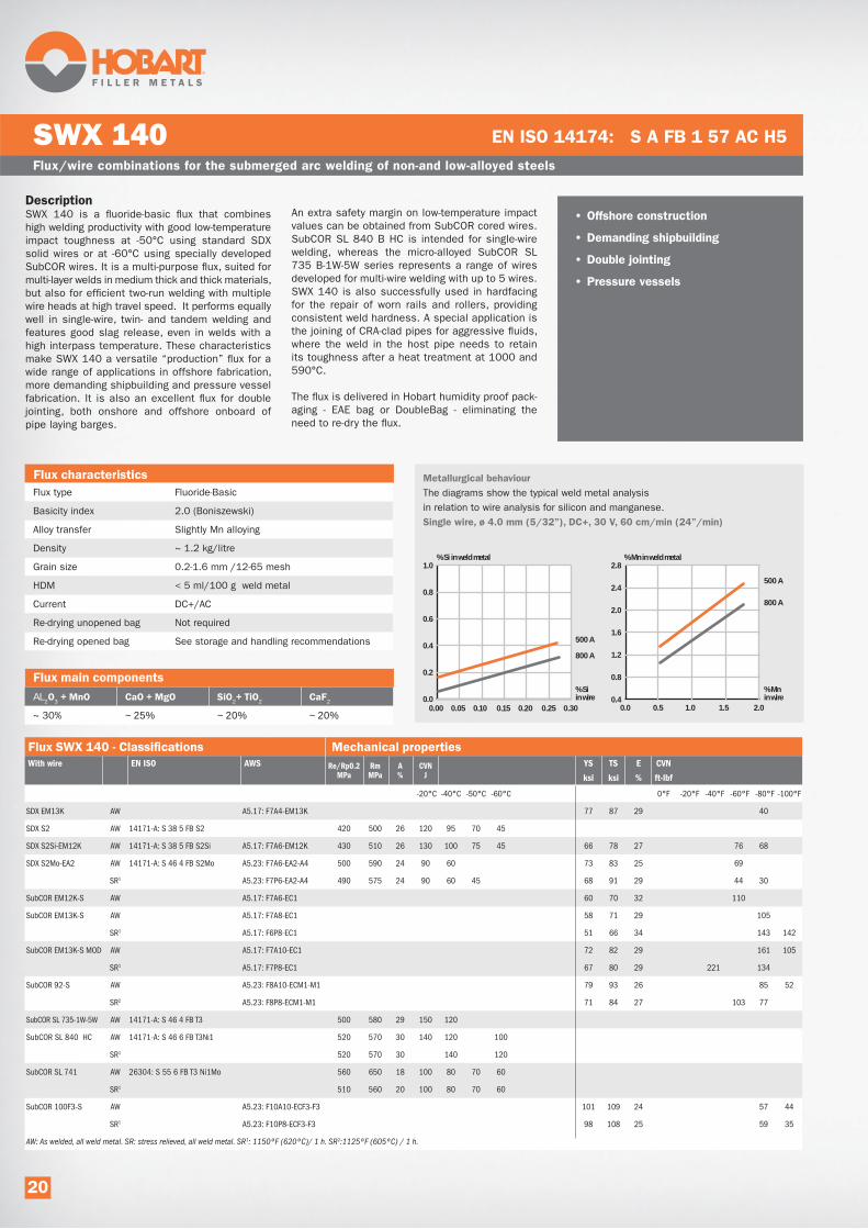
DescriptionSWX 140 is a fluoride-basic flux that combines
high welding productivity with good low-temperature
impact toughness at -50°C using standard SDX
solid wires or at -60°C using specially developed
SubCOR wires. It is a multi-purpose flux, suited for
multi-layer welds in medium thick and thick materials,
but also for efficient two-run welding with multiple
wire heads at high travel speed. It performs equally
well in single-wire, twin- and tandem welding and
features good slag release, even in welds with a
high interpass temperature. These characteristics
make SWX 140 a versatile “production” flux for a
wide range of applications in offshore fabrication,
more demanding shipbuilding and pressure vessel
fabrication. It is also an excellent flux for double
jointing, both onshore and offshore onboard of
pipe laying barges.
An extra safety margin on low-temperature impact
values can be obtained from SubCOR cored wires.
SubCOR SL 840 B HC is intended for single-wire
welding, whereas the micro-alloyed SubCOR SL
735 B-1W-5W series represents a range of wires
developed for multi-wire welding with up to 5 wires.
SWX 140 is also successfully used in hardfacing
for the repair of worn rails and rollers, providing
consistent weld hardness. A special application is
the joining of CRA-clad pipes for aggressive fluids,
where the weld in the host pipe needs to retain
its toughness after a heat treatment at 1000 and
590°C.
The flux is delivered in Hobart humidity proof pack-
aging - EAE bag or DoubleBag - eliminating the
need to re-dry the flux.
Flux/wire combinations for the submerged arc welding of non-and low-alloyed steels
SWX 140 EN ISO 14174: S A FB 1 57 AC H5
Flux type Fluoride-Basic
Basicity index 2.0 (Boniszewski)
Alloy transfer Slightly Mn alloying
Density ~ 1.2 kg/litre
Grain size 0.2-1.6 mm /12-65 mesh
HDM < 5 ml/100 g weld metal
Current DC+/AC
Re-drying unopened bag Not required
Re-drying opened bag See storage and handling recommendations
AL2 3 2 2 2
~ 30% ~ 25% ~ 20% ~ 20%
• Offshore construction
• Demanding shipbuilding
• Double jointing
• Pressure vessels
1.0
0.8
0.6
0.4
0.2
0.0
Metallurgical behaviour
The diagrams show the typical weld metal analysis
in relation to wire analysis for silicon and manganese.
Single wire, ø 4.0 mm (5/32”), DC+, 30 V, 60 cm/min (24”/min)
0.00 0.05 0.10 0.15 0.20 0.25 0.30
2.8
2.4
2.0
1.6
1.2
0.8
0.4 0.0 0.5 1.0 1.5 2.0
500 A
800 A
% Si in wire
% Mn in wire
% Si in weld metal
500 A
800 A
% Mn in weld metal
With wire EN ISO AWS Re/Rp0.2MPa
RmMPa
A%
CVNJ
YS TS E CVN
ksi ksi % ft-lbf
-20°C -40°C -50°C -60°C 0°F -20°F -40°F -60°F -80°F -100°F
SDX EM13K AW A5.17: F7A4-EM13K 77 87 29 40
SDX S2 AW 14171-A: S 38 5 FB S2 420 500 26 120 95 70 45
SDX S2Si-EM12K AW 14171-A: S 38 5 FB S2Si A5.17: F7A6-EM12K 430 510 26 130 100 75 45 66 78 27 76 68
SDX S2Mo-EA2 AW 14171-A: S 46 4 FB S2Mo A5.23: F7A6-EA2-A4 500 590 24 90 60 73 83 25 69
SR1 A5.23: F7P6-EA2-A4 490 575 24 90 60 45 68 91 29 44 30
SubCOR EM12K-S AW A5.17: F7A6-EC1 60 70 32 110
SubCOR EM13K-S AW A5.17: F7A8-EC1 58 71 29 105
SR1 A5.17: F6P8-EC1 51 66 34 143 142
SubCOR EM13K-S MOD AW A5.17: F7A10-EC1 72 82 29 161 105
SR1 A5.17: F7P8-EC1 67 80 29 221 134
SubCOR 92-S AW A5.23: F8A10-ECM1-M1 79 93 26 85 52
SR2 A5.23: F8P8-ECM1-M1 71 84 27 103 77
SubCOR SL 735-1W-5W AW 14171-A: S 46 4 FB T3 500 580 29 150 120
SubCOR SL 840 HC AW 14171-A: S 46 6 FB T3Ni1 520 570 30 140 120 100
SR1 520 570 30 140 120
SubCOR SL 741 AW 26304: S 55 6 FB T3 Ni1Mo 560 650 18 100 80 70 60
SR1 510 560 20 100 80 70 60
SubCOR 100F3-S AW A5.23: F10A10-ECF3-F3 101 109 24 57 44
SR1 A5.23: F10P8-ECF3-F3 98 108 25 59 35
AW: As welded, all weld metal. SR: stress relieved, all weld metal. SR1: 1150ºF (620ºC)/ 1 h. SR2:1125ºF (605ºC) / 1 h.
20

Flux/wire combinations for the submerged arc welding of non-and low-alloyed steels
SWX 140 (continued) EN ISO 14174: S A FB 1 57 AC H5
Materials to be welded
Rel ≤ 355 MPa S235JR, A106 Gr. B, A333 Gr. 6,P235GH, S275JO, -40°C SDX S2Mo-EA2
S275JR, P295GH -50°C SDX S2, SDX S2Si-EM12K
Rel ≥ 355 MPa S355J2, S355N, P355NL1, X52, L360, S355MCD, -40°C SDX S2Mo-EA2
S355ML, P355GH -50°C SDX S2, SDX S2Si-EM12K
TS > 58 ksi A36, A709 Gr. 36, -60°F SubCOR EM12K-S
-100°F SubCOR EM13K-S MOD
TS > 65ksi A572 Gr. 50, A709 Gr. 50, A709 Gr. 50S, A992 -60°F SubCOR EM12K-S
-100°F SubCOR EM13K-S MOD
Rel ≥ 420 MPa S420N, S460ML, P420ML2, S420MCD, S420G2+M, -40°C SDX S2Mo-EA2, SDX S3Si-EH12
X60, L450
Rel ≥ 460 MPa S460M, S460ML, S460ML2, S460MCD, S460G2+M -40°C SDX S2 Mo-EA2, SDX S3Si-EH12, SubCOR SL 735-1W-5W
X65, L450 -60°C SubCOR SL 840 HC
Rel ≥ 500 MPa S500Q, S500QL, S500QL1, P500QL1, P500QL2, -50°C SubCOR 741
S500G2+M, S55Q, S550QL, S500QL1, X70, X75, X80 -60°C SubCOR SL 840 HC
TS > 70ksi A588, A516 Gr. 70 -60°F SubCOR EM12K-S
-100°F SubCOR EM13K-S MOD
TS > 75ksi A572 Gr. 60, A913 Gr. 60, A871 Gr. 60 -100°F SubCOR 92-S
TS > 80ksi A572 Gr. 65, A871 Gr. 65, A537 Class 2 -100°F SubCOR 92S
TS > 85ksi A710 Gr. A Class 3 ≤ 2” -100°F SubCOR 100F3-S
TS > 90ksi A710 Gr. A Class 1 ≤ 3/4" -100°F SubCOR 100F3-S
TS > 100ksi A514 >2 1/2" -100°F SubCOR 100F3-S
0.5% Mo P295GH, P355GH, 16Mo3, 17Mo3, 14Mo6 -40°C SDX S2Mo-EA1
Flux SWX 140 - Chemical composition all weld metal, typical values
%Si %Mo
SDX-EM13K 0.05 0.2 1.2
SDX S2 0.07 0.2 1.4
SDX S2Si-EM12K 0.07 0.3 1.4
SDX S2Mo-EA2 0.07 0.2 1.4 0.5
SubCOR EM12K-S 0.05 0.2 1.2
SubCOR EM13K-S 0.05 0.2 1.2
SubCOR EM13K-S MOD 0.08 0.3 1.2
SubCOR 92-S 0.08 0.2 1.3 1.6 0.2
SubCOR SL 735-1W-5W 0.05 0.3 1.4
SubCOR SL 840 HC 0.10 0.3 1.4 0.9
SubCOR SL 741 0.06 0.3 1.2 0.9 0.5
SubCOR 100F3-S 0.09 0.3 1.5 0.8 0.5
SDX S2
SDX S2Si-EM12K
SDX S2Mo-EA2
For the complete approval list please see Product Data Sheet or
contact the ITW Welding sales office
Aluminium/PE Bag EAE* 25 55
DoubleBag 1000 2200
*EAE Excess Air Evacuation
21

DescriptionHobart SWX 150 is a high basicity, fluoride-basic
agglomerated flux for low-temperature, high strength
and creep resistant applications, including CTOD
requirements. Its neutral character promotes a
homogeneous weld chemistry and consistent
mechanical properties throughout thick multi-layer
welds. It produces low oxygen weld metal (~300ppm),
resulting in excellent impact toughness down to
-60°C and below. SWX 150 has a very good slag
detachability, also in narrow gaps, along with
smooth bead finish and tie-in. SWX 150 can be
used in single- and multiple-wire operation and
performs equally well on AC and DC+.
It is used for normal construction steel, high strength
steel, low-temperature steel and creep resistant
steel in demanding sectors such as offshore
fabrication, pressure vessels and nuclear compo-
nents. Use of the flux in combination with Hobart
cored wires offers further opportunities to improve
weld metal quality and productivity, making use of
unique cored wire properties.
Typical CTOD test results with SDX S3Si-EH12K
solid wire, tested at -20°C: 1.01, 1.01, 1.09 mm.
The flux is delivered in Hobart humidity proof EAE
bag, eliminating the need to re-dry the flux.
Flux/wire combinations for the submerged arc welding of non-and low-alloyed steels
SWX 150 EN ISO 14174: S A FB 1 55 AC H5
Flux type Fluoride-basic
Basicity index 3.3 (Boniszewski)
Alloy transfer None
Density ~ 1.1 kg/litre
Grain size 0.2-1.6 mm /12-65 mesh
HDM < 5 ml/100 g weld metal
Current DC+/AC
Re-drying unopened bag Not required
Re-drying opened bag See storage and handling recommendations
Metallurgical behaviour
The diagrams show the typical weld metal analysis
in relation to wire analysis for silicon and manganese.
Single wire, ø 4.0 mm (5/32”), DC+, 30 V, 60 cm/min (24”/min)
AL2 3 2 2 2
~ 20% ~ 35% ~ 15% ~ 25%
0.6
0.5
0.4
0.3
0.2
0.1
0.00.00 0.05 0.10 0.15 0.20 0.25 0.30
2.0
1.6
1.2
0.8
0.4
0.0 0.0 0.5 1.0 1.5 2.0
500 A800 A
% Si in wire
% Mn in wire
% Si in weld metal
500 A800 A
% Mn in weld metal
• Offshore construction
• Offshore wind towers
• Civil construction
• Pressure vessels
• Nuclear applications
• Narrow gap welding
• Double-jointing
• High strength applications
With wire EN ISO AWS Re/Rp0.2MPa
RmMPa
A%
CVNJ
YS TS E CVN
ksi ksi % ft-lbf
0°C -20°C -30°C -40°C -50°C -60°C -70°C 0°F -20°F -40°F -60°F -80°F -100°F
SDX EM13K AW A5.17: F7A4-EM13K 68 74 27 42 28
SDX S2Si-EM12K AW 14171-A: S 38 5 FB S2Si A5.17: F7A6-EM12K 420 500 22 130 85 65 35 68 77 31 90 27
SDX S3Si-EH12K AW 14171-A: S 46 6 FB S3Si A5.17: F7A8-EH12K 490 550 29 140 115 80 60 74 83 31 142 122
SR1 A5.17: F7P8-EH12K 410 500 29 140 115 80 60 65 80 31 219 129
SDX S4-EH14 AW 14171-A: S 50 4 FB S4 540 630 22 65 55 40
SR1 450 550 22 60 55 40
SDX S2Mo-EA2 AW 14171-A: S 46 4 FB S2Mo A5.23: F7A6-EA2-A2 485 570 23 75 55 40 76 84 27 106 44
SR1 A5.23: F7P6-EA2-A2 460 510 24 70 50 35 72 82 30 109 60
SubCOR EM12K-S AW A5.17: F7A4-EC1 60 71 32 97
SubCOR EM13K-S AW A5.17: F7A8-EC1 64 73 30 160
SR1 A5.17: F6P8-EC1 52 67 35 154
SubCOR EM13K-S MOD AW A5.17: F7A8-EC1 70 79 29 103
SR1 A5.17: F7P8-EC1 65 78 32 36
SubCOR SL 731 AW 14171: S 46 4 FB T3 A5.17: F8A6-EC1 490 600 29 140 110 80 112 122 22 55 36
SR1 460 570 28 110 90 70
SDX S3Ni1Mo0.2-ENi5 AW 14171-A: S 46 6 FB S2Ni1Mo0.2 A5.23: F8A8-ENi5-Ni5 510 590 29 125 75 82 90 27 146
SR1 A5.23: F8P6-ENi5-Ni5 500 590 28 70 77 89 28 134 100
SDX S3Ni1Mo-EF3 AW 14171-A: S 62 6 FB S3Ni1Mo A5.23: F10A8-EF3-F3 640 730 22 110 75 60 50 98 107 24 99 72
SDX S3Ni2.5CrMo AW 26304: S 69 6 FB S3Ni2.5CrMo 710 800 18 95 75 65 55
SubCOR 92-S AW A5.23: F8A10-ECM1-M1 78 88 26 91 78
SR2 A5.23: F8P8-ECM1-M1 76 88 27 123 106
22

Flux/wire combinations for the submerged arc welding of non-and low-alloyed steels
SWX 150 (continued) EN ISO 14174: S A FB 1 55 AC H5
Flux SWX 150 - Chemical composition all weld metal, typical values
%Si %Mo %V
SDX EM13K 0.07 0.2 1.0
SDX S2Si-EM12K 0.07 0.3 0.9
SDX S3Si-EH12K 0.09 0.3 1.5
SDX S4-EH14 0.01 0.15 1.9
SDX S2Mo-EA2 0.07 0.2 0.9 0.5
SDX S2Ni1-ENi1 0.07 0.2 0.9 0.9
SDX S2Ni2-ENi2 0.08 0.2 1.0 2.1
SDX S3Ni1Mo0.2-ENi5 0.09 0.25 1.4 0.9 0.2
SDX S3Ni1Mo-EF3 0.09 0.2 1.5 0.9 0.5
SDX S3Ni2.5CrMo 0.07 0.2 1.4 0.5 2.5 0.5
SDX CrMo1-EB2R 0.07 0.3 0.9 1.1 0.5
SDX CrMo2-EB3R 0.07 0.3 0.6 2.2 1.0
SubCOR EM12K-S 0.05 0.2 0.9
SubCOR EM13K-S 0.07 0.2 1.0
SubCOR EM13K-S MOD 0.09 0.3 0.9
SubCOR 92-S 0.05 0.2 1.0 1.6 0.2
SubCOR F2-S 0.07 0.35 1.4 0.7 0.4
With wire EN ISO AWS Re/Rp0.2MPa
RmMPa
A%
CVNJ
YS TS E CVN
ksi ksi % ft-lbf
0°C -20°C -30°C -40°C -50°C -60°C -70°C 0°F -20°F -40°F -60°F -80°F -100°F
SubCOR F2-S AW A5.23: F10A10-ECF2-F2 95 104 23 86 58
SR1 A5.23: F10P10-ECF2-F2 91 101 25 39 28
SubCOR 100F3-S AW A5.23: F10A10-ECF3-F3 101 109 24 57 44
SR1 A5.23: F10P10-ECF3-F3 98 108 25 59 35
SubCOR 120-S AW A5.23: F11A10-ECM4-M4 111 118 23 77 52
SubCOR SL 741 AW 26304: S 55 6 FB T3 Ni1Mo 550 700 18 80 60
SubCOR SL 742 AW 26304: S 69 6 FB T3 Ni2.5CrMo A5.23: F11A8-ECF5-F5 720 820 20 145 125 100 112 122 22 34 33
SR3 26304: S 69 6 FB T3 Ni2.5CrMo 700 790 20 135 115 70
SubCor SL 745 AW 16304: S 89 4 FB T3Ni2.5Cr1Mo 920 1060 15 47
SDX S2Ni1-ENi1 AW 14171-A: S 42 4 FB S2Ni1 A5.23: F7A8-ENi1-Ni1 440 530 25 130 65 45 70 80 29 135 108
SR1 A5.23: F7P8-ENi1-Ni1 430 530 25 130 90 60 45 65 77 30 177 135
SDX S2Ni2-ENi2 AW 14171-A: S 46 7 FB S2Ni2 A5.23: F8A10-ENi2-Ni2 480 570 27 145 115 95 75 60 74 85 27 143 127
SR1 A5.23: F8P10-ENi2-Ni2 480 580 27 145 115 90 60 40 70 83 28 149 138
SubCOR Ni1-S AW A5.23: F7A8-ECNi1-Ni1 61 73 26 104
SR1 A5.23: F7P10-ECNi1-Ni1 58 71 33 127 191
SubCOR W-S AW A5.23: F7A6-ECW-W 71 80 28 129 66
SDX CrMo1-EB2R SR4 24598: S S CrMo1 FB A5.23: F8P2-EB2R-B2 490 620 22 100 80 80 91 25 129 88
SDX CrMo2-EB3R SR4 24598: S S CrMo2 FB A5.23: F8P0-EB3R-B3 530 630 22 110 80 82 97 24 92 20
SubCOR B2-S SR4 A5.23: F9P2-ECB2-B2 93 96 23 92 18
SubCOR B3-S SR4 A5.23: F9P2-ECB3-B3 103 117 18 25
SubCOR SL P1 SR4 24598: S T Mo FB 480 560 22 220 200 180
SubCOR SL P1 MOD SR4 24598: S T MoVFB 420 530 22 70 40
SubCOR SL P11 SR4 24598: S T CrMo1 FB 510 600 26 200 150
SubCOR SL P12 MOD SR4 24598: ~S T CrMoV1 FB 540 630 17 +20°C:60
SubCOR SL P36 SR1 24598: S T Z FB 550 640 18 80 60 50
SubCOR SL P22 SR4 24598: S T CrMo2 FB 560 640 20 180
SubCOR SL P24 SR4 24598: S T Z FB 650 720 18 120 60
SubCOR SL P5 SR5 24598: S T CrMo5 FB 470 590 25 200 150
AW: as welded, all weld metal. SR: stress relieved, all weld metal. SR1: 1150ºF (620ºC) / 1 h. SR2: 1125ºF (605ºC) / 1 h. SR3: 1050ºF (565ºC) / 1 h, SR4: 1275ºF (690ºC) / 1 h. SR5: 1375ºF (745ºC) / 1 h.
23

Flux/wire combinations for the submerged arc welding of non-and low-alloyed steels
SWX 150 (continued) EN ISO 14174: S A FB 1 55 AC H5
Materials to be welded
Rel ≤ 355 MPa S235JR, A106 Gr. B, A333 Gr. 6,P235GH, S275JO, S275JR -50°C SDX S2Si-EM12K
-60°C SDX S3Si-EH12K
Rel ≥ 355 MPa S355J2, S355N, P355NL1, X52, L360, S355MCD, S355ML -50°C SDX S2Si-EM12K
-60°C SDX S3Si-EH12K
TS > 58 ksi A36, A709 Gr. 36, -40°F SubCOR EM12K-S
-80°F SubCOR EM13K-S
-100°F SubCOR EM13K-S MOD
TS > 65ksi A572 Gr. 50, A709 Gr. 50, A709 Gr. 50S, A992 -40°F SubCOR EM12K-S
-80°F SubCOR EM13K-S
-100°F SubCOR EM13K-S MOD
Rel ≥ 420 MPa S420N, S460ML, P420ML2, S420MCD, S420G2+M, X60, L450 -40°C SDX S2Mo-EA2, SDX S2Ni1-ENi1
-60°C SDX S3Si-EH12K
Rel ≥ 460 MPa S460M, S460ML, S460ML2, S460MCD, S460G2+M, X65, L450 -40°C SDX S2Mo-EA2, SubCOR SL 731
-60°C SDX S3Si-EH12K, SDX S2Ni1Mo0.2-ENi5
-70°C SDX S2Ni2-ENi2
Rel ≥ 500 MPa S500QL, S500QL1, P500QL1, P500QL2, X70, S500G2+M, -40°C SDX S4-EH12
B1 4NVE 500, X70, X80 -60°C SubCOR SL 741
Rel ≥ 620 MPa S550QL, NVE550, S600Q1, S620Q, S620QL, NVE620 -40°C SDX S3Ni1.5CrMo
-60°C SDX S3Ni1Mo-EF3
Rel ≥ 690 MPa S690Q, S690QL, S690QL1, NVE690, X100 -60°C SubCOR SL 742, SDX S3Ni2.5CrMo
Rel ≥ 890 MPa S890QL1, S960QL1, A714, A709, A515, A517 -40°C SubCOR SL 745
Flux SWX 150 - Chemical composition all weld metal, typical values
%Si %Mo %V
SubCOR 100F3-S 0.09 0.3 1.5 0.8 0.5
SubCOR 120-S 0.06 0.3 1.5 0.3 2.4 0.4
SubCOR Ni1-S 0.05 0.2 1.0 1.6 0.2
SubCOR W-S 0.03 0.4 0.6 0.5 0.5 0.4
SubCOR B2-S 0.07 0.4 0.4 1.2 0.5
SubCOR B3-S 0.1 0.4 0.4 2.3 1.0
SubCOR SL 731 0.08 0.6 1.7
SubCOR SL 741 0.06 0.3 1.2 0.9 0.5
SubCOR SL 742 0.07 0.35 1.6 0.4 2.1 0.4
SubCor SL 745 0.08 0.4 1.6 1.0 2.2 0.5
SubCOR SL P1 0.06 0.2 1.2 0.5
SubCOR SL P1 MOD 0.05 0.3 1.0 0.4 0.2 0.55 0.3
SubCOR SL P11 0.07 0.3 1.1 1.2 0.5
SubCOR SL P12 MOD 0.10 0.5 0.9 1.1 0.3 1.2 0.25
SubCOR SL P36 0.05 0.3 1.3 0.5
SubCOR SL P22 0.09 0.3 1.1 2.3 1.1
SubCOR SL P24 0.1 0.3 1.2 2.5 1.0 0.2
SubCOR SL P5 0.05 0.4 1.1 5 0.6
24
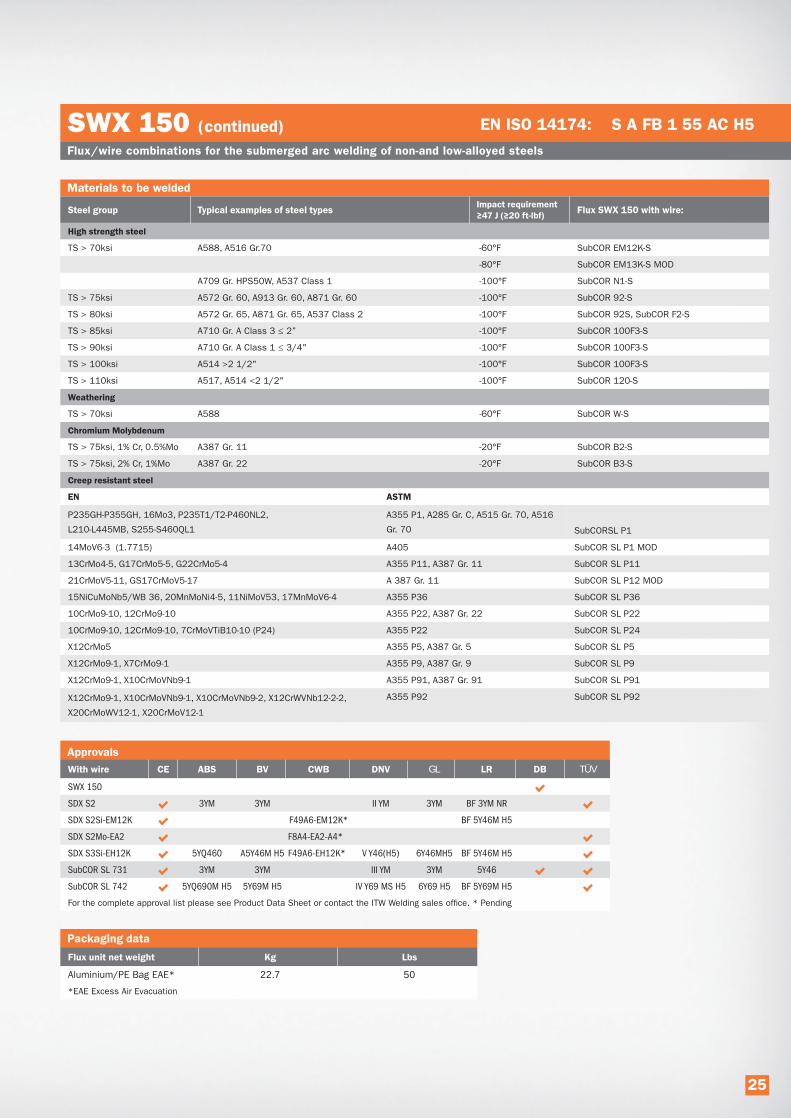
GL TÜV
SWX 150
SDX S2 3YM 3YM II YM 3YM BF 3YM NR
SDX S2Si-EM12K F49A6-EM12K* BF 5Y46M H5
SDX S2Mo-EA2 F8A4-EA2-A4*
SDX S3Si-EH12K 5YQ460 A5Y46M H5 F49A6-EH12K* V Y46(H5) 6Y46MH5 BF 5Y46M H5
SubCOR SL 731 3YM 3YM III YM 3YM 5Y46
SubCOR SL 742 5YQ690M H5 5Y69M H5 IV Y69 MS H5 6Y69 H5 BF 5Y69M H5
For the complete approval list please see Product Data Sheet or contact the ITW Welding sales office. * Pending
EN ASTM
P235GH-P355GH, 16Mo3, P235T1/T2-P460NL2,
L210-L445MB, S255-S460QL1
A355 P1, A285 Gr. C, A515 Gr. 70, A516
Gr. 70 SubCORSL P1
14MoV6-3 (1.7715) A405 SubCOR SL P1 MOD
13CrMo4-5, G17CrMo5-5, G22CrMo5-4 A355 P11, A387 Gr. 11 SubCOR SL P11
21CrMoV5-11, GS17CrMoV5-17 A 387 Gr. 11 SubCOR SL P12 MOD
15NiCuMoNb5/WB 36, 20MnMoNi4-5, 11NiMoV53, 17MnMoV6-4 A355 P36 SubCOR SL P36
10CrMo9-10, 12CrMo9-10 A355 P22, A387 Gr. 22 SubCOR SL P22
10CrMo9-10, 12CrMo9-10, 7CrMoVTiB10-10 (P24) A355 P22 SubCOR SL P24
X12CrMo5 A355 P5, A387 Gr. 5 SubCOR SL P5
X12CrMo9-1, X7CrMo9-1 A355 P9, A387 Gr. 9 SubCOR SL P9
X12CrMo9-1, X10CrMoVNb9-1 A355 P91, A387 Gr. 91 SubCOR SL P91
X12CrMo9-1, X10CrMoVNb9-1, X10CrMoVNb9-2, X12CrWVNb12-2-2,
X20CrMoWV12-1, X20CrMoV12-1
A355 P92 SubCOR SL P92
Aluminium/PE Bag EAE* 22.7 50
*EAE Excess Air Evacuation
Flux/wire combinations for the submerged arc welding of non-and low-alloyed steels
SWX 150 (continued) EN ISO 14174: S A FB 1 55 AC H5
Materials to be welded
TS > 70ksi A588, A516 Gr.70 -60°F SubCOR EM12K-S
-80°F SubCOR EM13K-S MOD
A709 Gr. HPS50W, A537 Class 1 -100°F SubCOR N1-S
TS > 75ksi A572 Gr. 60, A913 Gr. 60, A871 Gr. 60 -100°F SubCOR 92-S
TS > 80ksi A572 Gr. 65, A871 Gr. 65, A537 Class 2 -100°F SubCOR 92S, SubCOR F2-S
TS > 85ksi A710 Gr. A Class 3 ≤ 2” -100°F SubCOR 100F3-S
TS > 90ksi A710 Gr. A Class 1 ≤ 3/4" -100°F SubCOR 100F3-S
TS > 100ksi A514 >2 1/2" -100°F SubCOR 100F3-S
TS > 110ksi A517, A514 <2 1/2" -100°F SubCOR 120-S
TS > 70ksi A588 -60°F SubCOR W-S
TS > 75ksi, 1% Cr, 0.5%Mo A387 Gr. 11 -20°F SubCOR B2-S
TS > 75ksi, 2% Cr, 1%Mo A387 Gr. 22 -20°F SubCOR B3-S
25

DescriptionHobart SWX 220 an agglomerated neutral basic flux
for the single- or multi-run welding of stainless steel
in all plate thicknesses. It can be combined with
a wide range of SDX subarc wires for the welding
of all standard austenitic stainless steel grades,
for duplex and super duplex stainless steel, for
dissimilar joints and for higher alloyed stainless
steel grades. Multi-run welding is favoured by
excellent slag detachability and smooth side-wall
blending, while the overall weld appearance is very
nice. It yields welds with good mechanical prop-
erties, including excellent low-temperature impact
toughness.
A wide range of applications are found in transport
and processing installations in the offshore oil and
gas and petrochemical industries, in tanks and
appliances of chemical tankers, in paper and pulp
processing plants and in nuclear power stations.
The flux is delivered in Hobart humidity proof EAE
bag, eliminating the need to re-dry the flux.
Flux/wire combinations for the submerged arc welding of stainless steel
SWX 220 EN ISO 14174: S A AF 2 DC
Flux type Aluminate-Fluoride
Basicity index 1.7 (Boniszewski)
Alloy transfer none
Density ~ 1.2 kg/litre
Grain size 0.2-1.6 mm /12-65 mesh
Current DC+
Re-drying unopened bag Not required
Re-drying opened bag See storage and handling recommendations
AL2 3 2 2 2
~30% ~25% ~20% ~20%
• Offshore fabrication
• Petrochemical industry
• Chemical tankers
• Duplex grades
• Nuclear applications
• Paper and pulp plants
• Equipment for the food industry
Flux SWX 220 - Chemical composition all weld metal, typical values
%Si %Mo
SDX 308L 0.02 0.6 1.4 19.5 10.0 7
SDX 347 0.04 0.6 1.0 19.1 9.3 0.5 8
SDX 316L 0.02 0.6 1.4 18.3 11.3 2.8 8
SDX 317L 0.02 0.6 1.4 19.5 14.3 3.5 6
SDX 309L 0.02 0.6 1.4 23.0 14.2 2.8 10
SDX 309LMo 0.02 0.6 1.4 21.5 14.2 2.8 12
SDX 2209 0.02 0.7 1.2 22.5 9.0 3.2 0.13 48
SDX 2594 0.01 0.45 0.6 22.5 9.2 4.0 0.26 42
With wire EN ISO AWS Re/Rp0.2MPa
RmMPa
A%
CVNJ
YS TS E CVN
ksi ksi % ft-lbf
-20°C -40°C -60°C -196°C -4°F -40°F 76°F -321°F
SDX 308L 14343-A: S 19 9 L A5.9: ER308L 390 550 36 100 60 50 57 80 36 74 44 37
SDX 347 14343-A: S 19 9 Nb A5.9: ER347 440 620 36 100 80 20 64 90 36 74 59 15
SDX 316L 14343-A: S 19 12 3 L A5.9: ER316L 390 560 36 100 90 40 57 81 36 74 66 30
SDX 317L 14343-A: S 19 13 4 L A5.9: ER317L 430 600 30 90 50 40 62 87 30 66 37 30
SDX 309L 14343-A: S 23 12 L A5.9: ER309L 420 580 33 90 65 35 61 84 90 66 48 26
SDX 309LMo 14343-A: S 23 12 2 L 420 620 33 90 61 90 90 66
SDX 2209 14343-A: S 22 9 3 N L A5.9: ER2209 620 780 26 130 100 80 55 90 113 26 96 74 59 41
SDX 2594 14343-A: S 25 9 4 N L A5.9: ER2594 630 830 28 80 60 91 120 28 59 44
26

Flux/wire combinations for the submerged arc welding of stainless steel
SWX 220 (continued) EN ISO 14174: S A AF 2 DC
Materials to be welded
AISI
304 X4 CrNi 18 10 1.4301 S30409 SDX 308L
304L X2 CrNi 19 11 1.4306 S30403 SDX 308L
304LN X2 CrNiN 18 10 1.4311 S30453 SDX 308L
316 X4 CrNiMo 17 12 2 1.4401 S31600 SDX 316L
316 X4 CrNiMo 17 13 3 1.4436 SDX 316L
316L X2 CrNiMo 17 12 2 1.4404 S31603 SDX 316L
316L X2 CrNiMo 18 14 3 1.4435 S31603 SDX 316L
317L X2 CrNiMoN 17 13 5 1.4439 S31726 SDX 317L
321 X6 CrNiTi 18 10 1.4541 S32100 SDX 347, SDX 308L for service temperatures below 400°C
347 X6 CrNiNb 18 10 1.4550 S34700 SDX 347, SDX 308L for service temperatures below 400°C
X2 CrNiMoN 22 5 3 1.4462 SDX 2209
1.4507 SDX 2594
Dissimilar welds, moderate dilution SDX 309L
Dissimilar welds, high dilution, hot crack resistant SDX 309LMo
Aluminium/PE Bag EAE* 25 55
*EAE Excess Air Evacuation
27
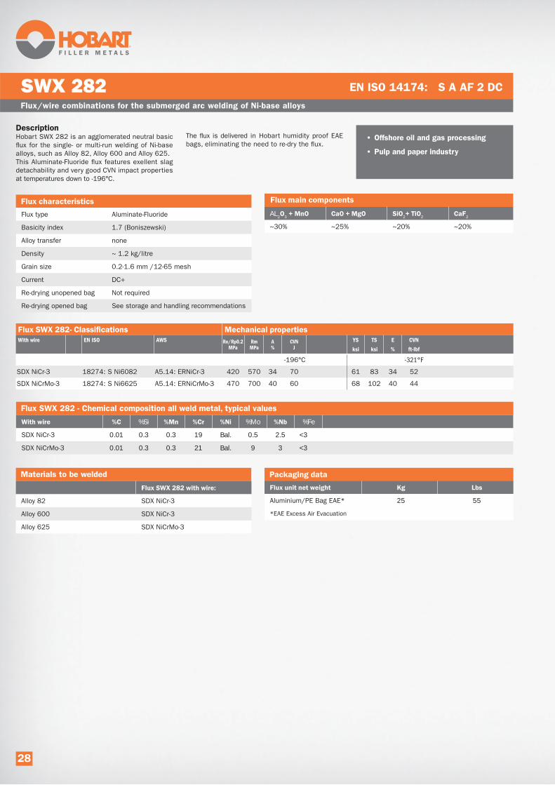
DescriptionHobart SWX 282 is an agglomerated neutral basic
flux for the single- or multi-run welding of Ni-base
alloys, such as Alloy 82, Alloy 600 and Alloy 625.
This Aluminate-Fluoride flux features exellent slag
detachability and very good CVN impact properties
at temperatures down to -196°C.
The flux is delivered in Hobart humidity proof EAE
bags, eliminating the need to re-dry the flux.
Flux/wire combinations for the submerged arc welding of Ni-base alloys
SWX 282 EN ISO 14174: S A AF 2 DC
Flux type Aluminate-Fluoride
Basicity index 1.7 (Boniszewski)
Alloy transfer none
Density ~ 1.2 kg/litre
Grain size 0.2-1.6 mm /12-65 mesh
Current DC+
Re-drying unopened bag Not required
Re-drying opened bag See storage and handling recommendations
AL2 3 2 2 2
~30% ~25% ~20% ~20%
• Offshore oil and gas processing
• Pulp and paper industry
Flux SWX 282 - Chemical composition all weld metal, typical values
%Si %Mo %Fe
SDX NiCr-3 0.01 0.3 0.3 19 Bal. 0.5 2.5 <3
SDX NiCrMo-3 0.01 0.3 0.3 21 Bal. 9 3 <3
Materials to be welded
Alloy 82 SDX NiCr-3
Alloy 600 SDX NiCr-3
Alloy 625 SDX NiCrMo-3
Aluminium/PE Bag EAE* 25 55
*EAE Excess Air Evacuation
With wire EN ISO AWS Re/Rp0.2MPa
RmMPa
A%
CVNJ
YS TS E CVN
ksi ksi % ft-lbf
-196°C -321°F
SDX NiCr-3 18274: S Ni6082 A5.14: ERNiCr-3 420 570 34 70 61 83 34 52
SDX NiCrMo-3 18274: S Ni6625 A5.14: ERNiCrMo-3 470 700 40 60 68 102 40 44
28

DescriptionAcid aluminium-silicate, agglomerated flux designed
for submerged strip cladding with stainless strips
on mild or low alloyed steel. It has good welding
characteristics and gives a smooth bead appear-
ance and easy slag removal.
SWX 305 is a non-alloying flux. The flux is delivered
in Hobart humidity proof EAE bag, eliminating the
need to re-dry the flux.
Flux/strip combinations for the SAW strip cladding of stainless strips
SWX 305 EN ISO 14174: S A AAS 2B DC
Flux type Acid-Aluminium-Silicate
Basicity index 1.1
Alloy transfer Non-alloying
Density ~ 1.1 kg/litre
Grain size 0.2-1.6 mm /12-65 mesh
Current DC+
Re-drying unopened bag Not required
Re-drying opened bag See storage and handling recommendations
AL2 3 2 2 2
~ 20% ~ 5% ~ 10% ~ 60%
• Offshore fabrication
• Pressure vessels
• Petrochemical industry
• Paper and pulp plants
• Offshore oil and gas processing
Flux SWX 305 - Chemical composition all weld metal, typical values
%Si %Mo
Cromastrip 308L 0.02 0.6 1.0 19.0 10.5 0.1 0.03 ~6
Cromastrip 316L 0.02 0.7 1.1 18.0 13.0 2.2 0.02 ~7
Cromastrip 347 0.02 0.7 1.1 19.0 10.5 0.1 0.4 0.03 ~8
(All analyses in 2nd layer, 1st layer welded with Cromastrip 309L.)
Aluminium/PE Bag EAE* 25 55
*EAE Excess Air Evacuation
29

DescriptionHobart SWX 330 is a fluoride-basic, non-alloying
agglomerated flux designed for standard speed
electroslag strip cladding with austenitic stainless
strips of the AWS EQ300 series. It has a high cur-
rent carrying capacity and can be used for single or
multi layer cladding.
It features excellent slag removal, also on preheat-
ed surfaces, leaving a bright deposit with smooth
overlap between runs. The flux is delivered in
Hobart humidity proof EAE bag, eliminating the
need to re-dry the flux.
Flux/strip combinations for electroslag strip cladding
SWX 330 EN ISO 14174: ES A FB 2B DC
Flux type Fluoride-basic
Basicity index 3.2 (Boniszewski)
Alloy transfer None
Density 1.1 kg/litre
Grain size 0.2-1.2 mm /12-65 mesh
Current DC+
Re-drying unopened bag Not required
Re-drying opened bag See storage and handling recommendations
AL2 3 2 2 2
~ 25% ~ 0% ~ 10% ~ 65%
• Pressure vessels
• Petrochemical industry
• Paper and pulp plants
• Offshore oil and gas processing
• Nuclear
Flux SWX 330 - Chemical composition all weld metal, typical values
%Si %Mo
Cromastrip 21.11 L 0.02 0.5 1.2 20.0 11.0 0.2 0.05 ~4 308L
Cromastrip 21.13.3 L 0.02 0.5 1.3 19.0 13.0 3.0 0.05 ~6 316L
Cromastrip 21.11 LNb 0.02 0.5 1.2 20.0 11.0 0.2 0.4 0.05 ~4 347
(Single layer composition. Parameters: 1350 A, 25 V, v travel 22 cm/min. (9”/min))
Aluminium/PE Bag EAE* 25 55
*EAE Excess Air Evacuation
30

Aluminium/PE Bag EAE* 22.7 50
*EAE Excess Air Evacuation
DescriptionHobart SWX 382 is a high basic, non-alloying,
agglomerated flux designed for standard speed
electroslag strip cladding with Ni-based strips.
It has a high current carrying capacity and can be
used for single or multi layer cladding with strips.
It features excellent slag removal, also on preheat-
ed surfaces, leaving a bright deposit with smooth
overlap between runs. The flux is delivered in
Hobart humidity proof EAE bag, eliminating the
need to re-dry the flux.
Flux/strip combinations for electroslag strip cladding
SWX 382 EN ISO 14174: ES A AF 2B DC
Flux type Aluminate-fluoride
Basicity index 3.7 (Boniszewski)
Alloy transfer None
Density 1.1 kg/litre
Grain size 0.2-1.2 mm /16-65 mesh
Current DC+
Re-drying unopened bag Not required
Re-drying opened bag See storage and handling recommendations
AL2 3 2 2 2
~ 20% ~5% ~ 10% ~ 60%
• Pressure vessels
• Petrochemical industry
• Paper and pulp plants
• Oil and gas processing
Flux SWX 382 - Chemical composition all weld metal, typical values
%Si %Mo %Fe
Cromastrip NiCr-3* 0.03 0.6 2.7 18.0 bal. 2.1 9
Cromastrip NiCr-3** 0.02 0.5 3.0 19.5 bal. 2.3 4 Alloy 82
Cromastrip NiCrMo-3* 0.03 0.4 0.3 20.0 bal. 9 2.9 9
Cromastrip NiCrMo-3** 0.02 0.3 0.2 21.5 bal. 9 3.2 4 Alloy 625
(* 1st layer, 2 mm below surface. Welding parameters: 1200A/23V/18 cm/min. Strip 60 x 0.5 mm.)
(** 2nd layer, 2 mm below surface. Welding parameters: 1200A/23V/18 cm/min. Strip 60 x 0.5 mm. )
31
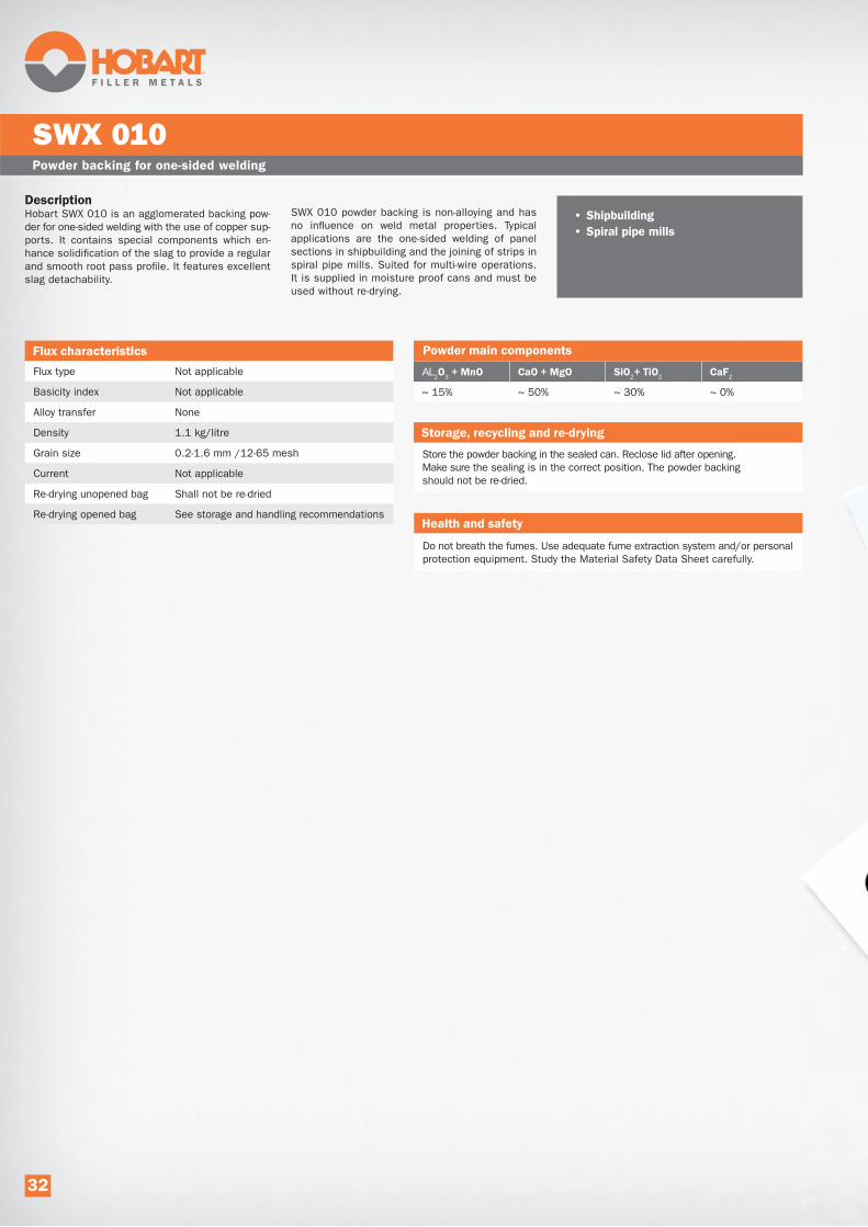
DescriptionHobart SWX 010 is an agglomerated backing pow-
der for one-sided welding with the use of copper sup-
ports. It contains special components which en-
hance solidification of the slag to provide a regular
and smooth root pass profile. It features excellent
slag detachability.
SWX 010 powder backing is non-alloying and has
no influence on weld metal properties. Typical
applications are the one-sided welding of panel
sections in shipbuilding and the joining of strips in
spiral pipe mills. Suited for multi-wire operations.
It is supplied in moisture proof cans and must be
used without re-drying.
Powder backing for one-sided welding
SWX 010
Flux type Not applicable
Basicity index Not applicable
Alloy transfer None
Density 1.1 kg/litre
Grain size 0.2-1.6 mm /12-65 mesh
Current Not applicable
Re-drying unopened bag Shall not be re-dried
Re-drying opened bag See storage and handling recommendations
AL2 3 2 2 2
~ 15% ~ 50% ~ 30% ~ 0%
• Shipbuilding
• Spiral pipe mills
Store the powder backing in the sealed can. Reclose lid after opening.
Make sure the sealing is in the correct position. The powder backing
should not be re-dried.
Do not breath the fumes. Use adequate fume extraction system and/or personal
protection equipment. Study the Material Safety Data Sheet carefully.
32

Approval Certificates
An ITW company
Certificate number
530203
In accordance with
Date: 01-10-2013
Your order:
98652
Your order d
ate: 27-09-2013
Our order:
130057
Your reference
:
Our reference
:
Invoicing address
Ship-to
Customer n
o.: 10090
Customer:
Customer:
Address:
Address:
Contact:
Contact:
Phone:
Phone:
E-mail:
E-mail:
Delivered product
Chemical analysis
Descriptio
n:
Al 2O3+
MnO:
37%
Item no.:
CaF 2:
14%
Lot no.:
131406
CaO+MgO:
21%
Quantity kg
: 50
SiO 2+TiO 2:
22%
Particle size
Cumulative
2.0 mm
1.6 mm
1.0 mm
0.5 mm
0.25 mm
0%
5%
28%
83%
100%
Classificatio
n
Comments
Please re
fer any q
ueries t
o:
SWELDX AB, Box 9
246, SE-400 95 G
öteborg, Sweden, +
46 31 787 50 17
Anna Cyrwus
ality M
anager
EN ISO 14174: S
A AB 1 67 AC H5
This product
is supplied under a
QA Programme fu
lfilling th
e EN ISO 9001 st
andard.
This is a
computer g
enerated document. N
o signature needed.
31 186 641 456
31 186 641 456
dir@itw
-welding.com
dir@itw
-welding.com
SWX 135 25 kg Al b
ag EAE
135022500H
Dimitri
Rijnen
Dimitri
Rijnen
ITW Welding Products
BV
Edisonstr
aat 10
P. O. B
ox 1551
1908-12-04
3260
LD Oud Beijerla
nd
LD Oud Beijerla
nd
The Netherlands
The Netherlands
ITW Welding Products
BV
Inspection certif
icate
EN 10204 - 3.1
Dimitri
Rijnen
Peter Jeiru
d
AT/NIP no.: 5252429053
Calvia Sp. z
o.o. is a su
bsidiary
of SWELDX AB, S
weden
0%
5%
28%
4: S A AB 1 67 AC H5
Certificate number
In accordance with
Your order:
98652
Your order d
ate: 27-09-2013
Your reference
:
Invoicing address
Delivered product
Descriptio
n:
Item no.:
Lot no.:
131406
Quantity kg
: 50
2.0 mm
1.6 mm
Customer n
o.: 10090
Customer:
Address:
Contact:
Phone:
E-mail:
31 186 641 456
dir@itw
-welding
SWX 135 2
13502250
Dimitri
Rijnen
ITW Welding Products
P. O. B
ox 1551
3260
LD Oud Beijerla
nd
The Netherlands
Ins
Dimitri
Rijnen
to:
46, SE-400 95 G
öteborg, Sweden, +
46 31 787 50 17
er
r a Q
A Programme fulfill
ing the EN IS
O 900
ed document. N
o signature needed.
AT/NIP no.: 5252429053
Calvia Sp. z
o.o. is a su
bsidiary
of SWELD
ELDX AB, 001 standard
%
d.
BSweden
VdTÜV-Kennblatt für Schweißzusätze1 Hersteller/LiefererSWELDX ABS 400 95 Göteborg, Schweden
Kennblatt- Nummer:12401.00
06.12
2SWELDX S 2DIN EN ISO 14171 - S2
3
0,1 - 1,6 mm
Anga-
desHer-
Draht-Pulver-Kombination
4
7
13
1510
unbegrenzt
G+, W
350
----50
---
---
Bemerkungen:
16 Die Werkstoffeinteilung entspricht ISO 15608:2000
19
2326
27
°C
°C
28
°C
2930
3132
6
9 SWELDX 120DIN EN 760 - SA AB 157 AC H5
ben
lersstel-
20
Erläuterungen: angelassenlösungsgeglühtu. abgeschrecktnormalgeglüht
A -L -
N -
spannungsarmgeglühtstabilgeglühtungeglühtvergütet
S -St-U -V - weichgeglüht
W -
Gleichstrom PluspolGleichstrom MinuspolWechselstromerscheint im selben Verlag
G+ -G- -
W - *) -
34
35
22
Nahtaufbau geeignet für: -Mehrlagenschweißung
wie Grundwerkstoff
Draht-Pulver:
5
Die Vervielfätigung, die Verbreitung, der Nachdruck und die Gesamtwiedergabe auf fotomechanischem oder ähnlichem Wege bleiben, auch bei auszugsweiser Verwertung, der
vorherigen Zustimmung des Herausgebers vorbehalten.
33
Wärmebehandlung (Wb) nach dem Schweißen und Werkstoffe
*) Herausgeber: Verband der TÜV e.V.
Vertrieb: TÜV-Media GmbH, Am Grauen Stein, 51105 Köln - Unternehmensgruppe TÜV Rheinland Group
TÜV Rheinland Group
Pos WbGruppe / Werkstoff 1
TextGruppe / Werkstoff 2
Bem.
U Gruppe 1.1U Gruppe 1.2
Drahtdurchmesser/Bandabmessungen[mm]Stromstärke
[A]Spannung
[V]Gerätevorschub
[cm/min]Arbeitstemperatur
[°C]
4,0
580
29
55
150 - 200
33

Packaging Solutions
FLUX
Hobart provides fluxes with maximum security related to
weld integrity. Hydrogen in the weld metal is the greatest
threat to weld integrity. Elevated levels of moisture in
the flux must be avoided at any cost. Since fluxes are
hygroscopic re-drying is generally recommended.
The results of re-drying depends on the use of proper
drying parameters and on moisture control.
The parameters recommended by flux producers do
generally not restore original moisture levels.
Consequently, prevention of moisture pick-up is extremely
important.
In order to protect the flux against moisture pick-up from
the air during storage and transportation, Hobart applies
moisture proof packaging as standard.
Packaging - EAE bag
For the standard weight bags, the Hobart solution is a
rigidly welded 5 layer polyethylene – aluminium foil bag.
The packaging material is resistant to any H2O transfer.
In addition Hobart applies EAE (Excess Air Evacuation).
Each bag passes a process where excess air is evacu-
ated, creating a reduced pressure atmosphere in the bag.
As a result moisture pick-up is drastically reduced and
products stored un-opened can be used without re-drying.
Packaging - DoubleBag
The Hobart solution for bulk packaging is a polypropylene
outer bag with an inside polyethylene-aluminium lining.
The packaging material is resistant to any H2O transfer.
After filling, the opening is welded. The moisture proper-
ties of the double bag are basically the same as for the
EAE bag. Moisture-pick up is drastically reduced and
products stored un-opened can be used without re-drying.
The bottom of the DoubleBag features a 400 mm (16”)
long discharge spout, equipped with a patented locking
device to easily control and stop the flow of flux.
Two major user benefits
1. Dry flux means safe welding. The elimination of moisture
pick-up makes (possibly ineffective) re-drying redundant
and ensures moisture close to the levels as produced.
2. Re-drying is a costly procedure considering the
administration, energy consumption, operator handling
and equipment investment involved. Its elimination
from the production chain saves money and time, while
supporting the environment by reducing emissions from
energy consumption. Moreover, there is no risk of
increasing the dust content by handling the flux in
a re-drying process.
Finally, the effectiveness of re-drying depends highly on
the process. When the re-drying temperature is too low
or when the flux stays too short in the oven, the moisture
level may not be lowered sufficiently. This is difficult to
determine, as sophisticated laboratory equipment is
required to test the actual moisture level of the flux.
Wires
Hobart wires are supplied in accordance with the market
requirements. Hobart has defined a standard range of
spools and weights, where the target is to always supply
off the shelf. In addition Hobart wires are available in
different special packaging executions for specific
customer needs.
34
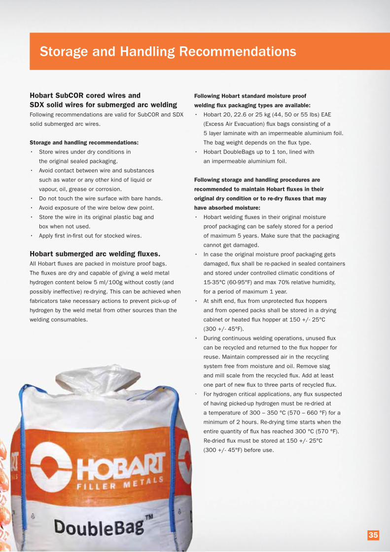
Storage and Handling Recommendations
Hobart SubCOR cored wires and
SDX solid wires for submerged arc welding
Following recommendations are valid for SubCOR and SDX
solid submerged arc wires.
Storage and handling recommendations:
• Store wires under dry conditions in
the original sealed packaging.
• Avoid contact between wire and substances
such as water or any other kind of liquid or
vapour, oil, grease or corrosion.
• Do not touch the wire surface with bare hands.
• Avoid exposure of the wire below dew point.
• Store the wire in its original plastic bag and
box when not used.
• Apply first in-first out for stocked wires.
Hobart submerged arc welding fluxes.
All Hobart fluxes are packed in moisture proof bags.
The fluxes are dry and capable of giving a weld metal
hydrogen content below 5 ml/100g without costly (and
possibly ineffective) re-drying. This can be achieved when
fabricators take necessary actions to prevent pick-up of
hydrogen by the weld metal from other sources than the
welding consumables.
Following Hobart standard moisture proof
welding flux packaging types are available:
• Hobart 20, 22.6 or 25 kg (44, 50 or 55 lbs) EAE
(Excess Air Evacuation) flux bags consisting of a
5 layer laminate with an impermeable aluminium foil.
The bag weight depends on the flux type.
• Hobart DoubleBags up to 1 ton, lined with
an impermeable aluminium foil.
Following storage and handling procedures are
recommended to maintain Hobart fluxes in their
original dry condition or to re-dry fluxes that may
have absorbed moisture:
• Hobart welding fluxes in their original moisture
proof packaging can be safely stored for a period
of maximum 5 years. Make sure that the packaging
cannot get damaged.
• In case the original moisture proof packaging gets
damaged, flux shall be re-packed in sealed containers
and stored under controlled climatic conditions of
15-35°C (60-95°F) and max 70% relative humidity,
for a period of maximum 1 year.
• At shift end, flux from unprotected flux hoppers
and from opened packs shall be stored in a drying
cabinet or heated flux hopper at 150 +/- 25°C
(300 +/- 45°F).
• During continuous welding operations, unused flux
can be recycled and returned to the flux hopper for
reuse. Maintain compressed air in the recycling
system free from moisture and oil. Remove slag
and mill scale from the recycled flux. Add at least
one part of new flux to three parts of recycled flux.
• For hydrogen critical applications, any flux suspected
of having picked-up hydrogen must be re-dried at
a temperature of 300 – 350 °C (570 – 660 °F) for a
minimum of 2 hours. Re-drying time starts when the
entire quantity of flux has reached 300 °C (570 °F).
Re-dried flux must be stored at 150 +/- 25°C
(300 +/- 45°F) before use.
s
a
o
• F
o
a
m
e
R
(
35

Successful submerged arc welding is not restricted to choosing the correct flux and wire
to achieve the required mechanical properties, but also deals with setting-up the process
in the best possible manner to leverage the investment optimally.
Below, we will show examples of submerged arc process optimization and the benefits it brings
to fabricators. To understand these, it is first needed to define the different cost components.
Together they make up the basic cost structure of any manufacturing company.
Cost component Abbreviation Examples of cost included
Direct Material DM Raw materials, components, packaging material, material losses in the process such as scrap
Variable Overhead VOHEnergy costs for manufacturing process, process consumables,
wear parts, cost of temporary workers.
Variable cost VC The sum of DM+VOH. Also called Direct costs as they are zero if nothing is manufactured.
Direct Labor DLWages or salaries, social charges, work clothes, production bonuses, free meals,
transport to and from work etc. for blue collar operators in the work shop.
Fixed Overhead FOH
Rental of premises, leasing of equipment, white collar personnel including production
management, indirect blue collar personnel such as truck drivers and repair men,
costs for heating and lighting, connection fees for utilities and communication.
Sometimes also called Period Costs.
Capital costs CCCCapital costs for equipment, owned premises. Typically both calculated interests
and depreciation are included.
Manufacturing cost MC Sometimes denominated Fully absorbed manufacturing costs
Sales and Administration SG&A
Sales and Administration, typically abbreviated S&A or SG&A. General Management,
Sales, Accounting, Logistics, R&D, Engineering etc. Everything from salaries to
company cars, from office stationeries to outbound transport costs.
Total cost TC Also called Cost of Goods Sold.
Direct labor (DL)
DL is traditionally considered a direct cost, but in reality
it is not possible to influence short to medium term for
the vast majority of companies. Therefore Direct Labor is
regarded as a fixed cost in the Hobart benefit assessment.
Variable contribution
Variable contribution = Revenue - Direct Costs. This is a
key measurement, as it tells how much the sales of an
item contribute to cover fixed overheads. Because fixed
costs in principle do not change with the sales volume,
one could argue that the incremental variable contribution
is all profit, as soon as the total fixed costs have been
covered. When the concept Variable Margin is used,
it means the Variable Contribution in % of the Revenues.
Impact of welding
Welding consumables for SAW joining typically stand for
between 0.5 – 2% of the total cost of the welded object.
However, with a less feasible choice of consumables or
set-up of the welding process, the impact on manufactur-
ing cost will be far higher than this.
During our efforts to support our clients with SAW process
optimization, we have achieved significant improvements
with productivity gains of over 20%. When welding is the
bottleneck, selling the additional capacity significantly
improves the profit.
The diagram on the right is based on what we would
call typical distribution of the costs and revenues for
companies working with submerged arc welding of mild
and low-alloyed steels. Based on our experience the
majority of companies will not be too far off from this
estimation.
Full performance submerged arc welding pays back
36

ITW Welding has the intention to support clients to improve productivity and quality. All businesses are different.
Hence an individual assessment has to be conducted to identify the potential. Sometimes it is possible to come up
with improvements with the same leverage as above, sometimes the result is mainly savings in the direct cost area.
Here is a real example of what such activities could mean to a client in monetary terms:
Company: Spiral pipe mill
Action • Change of flux to Hobart SWX 135 and change of wire setup
• Traveling speed increased bij 18% from 2.0 to 2.4 m/min (79 to 94 inches/min)
• Net cycle time improvement 9.6%
Output of pipes before improvement 150.000 tons per annum 330.000 lbs per annum
Output of pipes after improvement 164.400 tons per annum 361.680 lbs per annum
Increased output 14.400 tons per annum 361.680 lbs per annum
Difference 9.6 %
Operating margin before improvement 9,9 %
Operating margin after improvement 14.1 %
Improved operating income in relation to flux consumption 14.87 EUR/kg flux used 8,77 USD/lb flux used
This case involves a company being in the fortunate situation where demand is higher than their output capabilities. Hobart regards the out-
come of the work done in co-operation with the client quite successful, with an improvement of the operating margin by 4.2 %-units. To express
the value in another sense, it accounted 14.87 EUR/kg (8.77 USD/lb) for every kg (lb) of flux consumed in the pipe manufacturing.
It is Hobart’s objective to be not only a supplier of welding consumables and equipment, but to support its clients in
improving their total welding operations. Aware that our customer’s success equals our own, we regard this a continuous
effort to be repeated frequently.
In the chart we have set the start-up output
at 100 and the invoiced sales price at 100,
and split the latter up in three portions:
1. Direct cost stand for 40% of the revenue.
2. Fixed overhead related to manufacturing
accounts for 35% of the revenue and
fixed sales and administration overhead
stands for 15% of the revenue, i.e.
in total 50% fixed costs before productivity
improvement.
3. A starting balance of 10% profit.
At 10% net increase in output, the company will
have to spend 10% more on direct costs
(i.e. material, energy etc. as mentioned above),
whereas the fixed overheads basically remain
unchanged. At this typical distribution between
direct and fixed costs the profit will increase by
60% from 10 to 16 and the operating margin
will go from 10% to 14.5%!
37

HOBART SubCOR Cored Wires for Submerged Arc Welding
The use of SubCOR flux cored wires in submerged arc
welding provides interesting options to influence weld
metal chemistry and thereby microstructure and mechanical
properties of the weld. In the same way as submerged arc
welding fluxes, the flux formulation of these wires promotes
a microstructure with a low level of inclusions. This trans-
lates in superior low-temperature impact toughness.
A high crack resistance is further promoted by the
Typical mechanical properties in the as welded condition obtained with universally applied welding flux SWX 110.
Rp 0.2 Rm CVN
Product name EN AWS Cond. (MPa) (ksi) (MPa) (ksi) (J) (ft-lbf)
-40°C -40ºF
SDX S2Mo-EA2 S 46 2 AB S2Mo F7A4-EA2-A2 AW 510 74 590 85 35 26
SubCOR SL 731 S 46 4 AB T3 AW 490 71 600 87 115 85
(Table 1.)
Another example is SubCOR SL 742, a cored wire for
the submerged arc welding of high strength steel for
low-temperature service. When used with SWX 150, a high
basicity flux for demanding multi-layer applications, it gives
comfortable safety margins for impact toughness at
Typical mechanical properties in the as welded condition obtained with high basic flux SWX 150
Rp 0.2 Rm CVN
Product name EN AWS Cond. (MPa) (ksi) (MPa) (ksi) (J) (ft-lbf)
-60°C -76ºF
SDX S3Ni2.5CrMo S 69 6 FB S3Ni2.5CrMo AW 710 103 800 116 55 40
SubCOR SL 742 S 69 6 FB T3 Ni2.5CrMo F11A8-ECF5-F5 AW 720 104 820 119 100 74
-20°C -4°F
SDX CrMo1-EB2R S S CrMo1 FB F8P2-EB2R-B2 SR 490 71 620 90 100 74
SubCOR SL P11 S T CrMo1 FB SR 510 74 600 90 200 147
combination of very low-hydrogen weld metal and
a favorable, fine microstructure of mainly acicular ferrite.
An example is SubCOR SL 731, a basic cored wire for
the submerged arc welding of non-alloyed and fine grain
steels. When used in combination with a universally
applied low basicity flux, such as SWX 110, it yields
superior low-temperature impact toughness over S2Mo-EA2
solid wire, at comparable yield strength levels (table 1).
low-temperatures compared with its solid wire equivalent
SDX S3Ni2.5CrMo (table 2). The same is valid for
SDX CrMo1-EB2R solid wire and SubCOR SL P11 in
the creep resistant range.
Additional benefits of SubCOR SL type cored wires• A higher safety margin on low-temperature impact toughness.
• Weld metal hydrogen <4 HDM can be reached.
• Totally insensitive for moisture pick-up, regardless climatic conditions.
• No special storage requirements. Can be stored as solid wires.
• Improved current transfer from contact tip, due to copper coating.
• Low contact tip wear.
• Greater crack resistance due to a favorable rounded bead shape with reduced depth-width ratio.
• Wide cast and low helix and moderate stiffness give consistent wire feeding and straight wire delivery from the contact tip.
• Available for a wide range of non- and low-alloyed steel grades.
• Any technically relevant alloy can be produced in small production units.
38
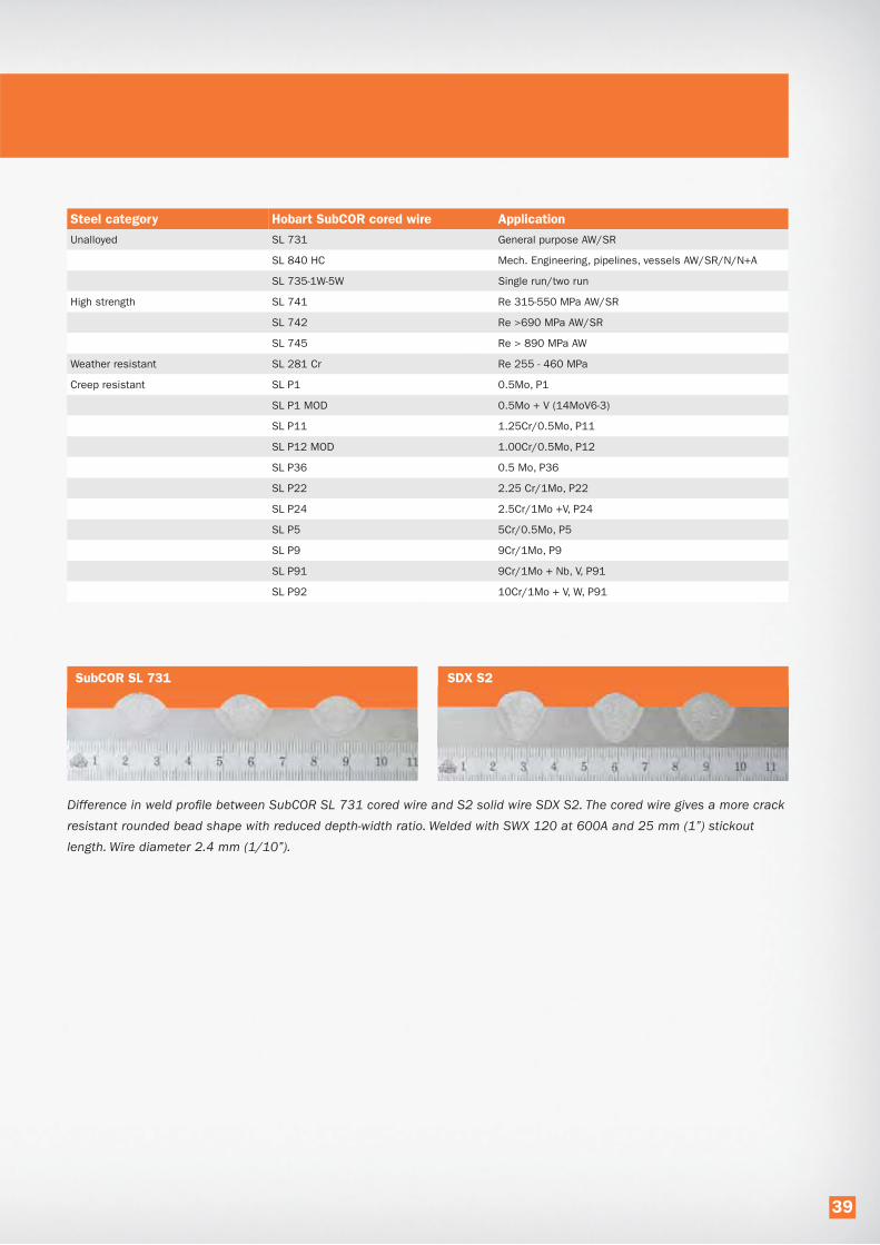
Steel category Hobart SubCOR cored wire Application
Unalloyed SL 731 General purpose AW/SR
SL 840 HC Mech. Engineering, pipelines, vessels AW/SR/N/N+A
SL 735-1W-5W Single run/two run
High strength SL 741 Re 315-550 MPa AW/SR
SL 742 Re >690 MPa AW/SR
SL 745 Re > 890 MPa AW
Weather resistant SL 281 Cr Re 255 - 460 MPa
Creep resistant SL P1 0.5Mo, P1
SL P1 MOD 0.5Mo + V (14MoV6-3)
SL P11 1.25Cr/0.5Mo, P11
SL P12 MOD 1.00Cr/0.5Mo, P12
SL P36 0.5 Mo, P36
SL P22 2.25 Cr/1Mo, P22
SL P24 2.5Cr/1Mo +V, P24
SL P5 5Cr/0.5Mo, P5
SL P9 9Cr/1Mo, P9
SL P91 9Cr/1Mo + Nb, V, P91
SL P92 10Cr/1Mo + V, W, P91
Difference in weld profile between SubCOR SL 731 cored wire and S2 solid wire SDX S2. The cored wire gives a more crack
resistant rounded bead shape with reduced depth-width ratio. Welded with SWX 120 at 600A and 25 mm (1”) stickout
length. Wire diameter 2.4 mm (1/10”).
SubCOR SL 731 SDX S2
39

Improved productivity from SubCOR metal-cored wires
SubCOR metal-cored wires for submerged arc welding
offer a number of advantages over the use of solid wires –
in terms of welding efficiency, weldability and weld quality.
• Potential for higher deposition rates than
solid wires at the same amperage.
• Potential to increase deposition without increasing
heat input, or to decrease heat input without
sacrificing deposition.
• Often better impact toughness and CTOD properties.
• A more favorable, broader shaped penetration
and fusion pattern.
• Greater tolerance to gaps, poor fit up,
and burn through.
Metal-cored wires are composite tubular electrodes
consisting of a metal sheath and a core of metallic and/
or non-metallic ingredients. An example of a metallic
ingredient is iron powder. The deposition efficiency will
increase with the amount of metallic ingredients in a
composite tubular wire. Non-metallic ingredients can, for
instance, be agents that clean and deoxidize the weld
or slag forming components. In a metal cored wire, the
current travels only through the sheath, whereas in a solid
wire the current travels through the entire cross-section of
the wire (Figure 1). Therefore, at an equivalent amperage
setting, a metal-cored wire will experience higher current
densities. The resulting increased melt-off rates, in combi-
nation with a high percentage of metallic particles, offers
increased deposition rates. The effect is most prominent at
higher welding currents, as can be seen from Figures 2 and 3.
Figure 1.
Current path through solid and metal-cored wires
Sheat
Metalpowder
Current Amps
density 3.14”*(d1
2)/4
Amps
3.14”*(d1
2-d2
2)/4=
300 A 400 A 500 A 600 A 700 A 600 A
DCEP MC 7.4 11.7 17.0 20.8 30.4 38.8
DCEP S 7 9.5 12.2 15.0 19.0 25
40.0
35.0
30.0
25.0
20.0
15.0
10.0
5.0
0.0
lbs/h
3.2 mm (1/8”) Diameter wire Comparisons (DCEP)
Figure 2.
Deposition rate
comparison between
solid and metal-cored
wires for submerged
arc welding.
400 A 500 A 600 A 700 A 800 A 900 A 1000 A
DCEP MC 11.0 14.0 17.3 25.3 32.2 40.7 48
DCEP S 11.3 14.2 16.3 18.7 22.3 28 32.2
60.0
50.0
40.0
30.0
20.0
10.0
0.0
lbs/h
4.0 mm (5/32”) Diameter wire Comparisons (DCEP)
18.0
15.8
13.6
11.3
9.0
6.8
4.5
2.3
0.0
kg/h
Figure 3.
Deposition rate
comparison between
solid and metal-cored
wires for submerged
arc welding.
27.2
22.7
18.1
13.6
9.1
4.5
0.0
kg/h
40

Following data results from a qualification test performed in offshore fabrication. The steel used was an offshore
grade with a minimum yield strength of 460 MPa (67 ksi) in 32 mm (1.25”) plate thickness. The joint preparation was
a 60° V-joint. The root pass was done by GMAW with an S2Ni1-ENi1 solid wire. For the submerged arc welding, variable
balance power sources were used in a triple wire set up.
Metric ImperialMC
vs
Solid
Solid wire Metal cored wire Solid wire Metal cored wire
Submerged arc wireHobart SDX
S3Ni1Mo.2-ENi5
Hobart
SubCOR 92-S
Hobart SDX
S3Ni1Mo.2-ENi5
Hobart SDX
S3Ni1Mo.2-ENi5
Flux Hobart SWX 150 Hobart SWX 150 Hobart SWX 150 Hobart SWX 150
Wire class EN ISO 14171/AWS A5.23 S3Ni1Mo0.2/ENi5 -/ECM1 S3Ni1Mo0.2/ENi5 -/ECM1
Wire set up 3 x 4.0 mm 3 x 4.0 mm 3 x 5/32" 3 x 5/32"
Process description AC/AC/AC AC/AC/AC AC/AC/AC AC/AC/AC
Parameters 30-35 V, 550-700 A 28-36 V, 600-700 A 30-35 V, 550-700 A 28-36 V, 600-700 A
Wire feed speed 125-190 cm/min 190-250 cm/min 50-75 inch/min 75-100 inch/min
Travel speed 107 cm/min 120 cm/min 42 inch/min 47 inch/min +12%
No. of passes 12 11 12 11 -1
Max interpass temperature 260 °C 260 °C 500 °F 500 °F
Peak heat input 3.3 kJ/mm 3.2 kJ/mm 84 kJ/inch 82 kJ/inch
Average heat input 3.1 kJ/mm 3.0 kJ/mm 79 kJ/inch 77 kJ/inch
AW yield strength 497 MPa 490 MPa 72.1 ksi 71.1 ksi
Cross weld tensile 500 MPa 498 MPa 72.6 ksi 72.1 ksi
CVN @ -40 °C (-40 °F) - Root 102 J 103 J 75 ft-lbs 76 ft-lbs
CVN @ -40 °C (-40 °F) - Cap 88 J 121 J 65 ft-lbs 89 ft-lbs +37%
CTOD @-10 °C (+14 °F) 1.27 mm 1.61 mm 0.050 inch 0.063 inch
Deposition rate 24.9 kg/h 30.6 kg/h 54.8 lbs/h 67.3 lbs/h +23%
This case represents well the difference between a metal-
cored and a solid wire in a 4.0 mm (5/32”) wire diameter
application. You will typically see both a productivity gain
as well as improved mechanical properties.
Productivity is, of course, always important in any business.
Metal-cored wires provide this. However, sometimes the
required mechanical properties are the limiting factor and,
in most cases, these can be met by exchanging solid to
MC wires, without sacrificing productivity. There are also
cases, mainly in high strength and high temperature
applications, where the mechanical properties cannot be
met without exchanging the solid wire with a cored wire.
Estimating deposition rates
for metal-cored and solid wires
An efficiency of 99% is used when calculating the deposi-
tion rates of solid wires when used in the SAW process.
In comparison, metal-cored wires use a 97% efficiency rate
for calculating deposition rates, whereas efficiency rates
of 92% can be realized with flux-cored wire. It should also
be noted that metal-cored wires for SAW are formulated
differently than those metal-cored wires formulated to run
with shielding gas. They show differences in deposition
efficiency, as well as in the weight of the wire. By using the
numbers below one can create a simple spread sheet to
calculate deposition rates based off of wire feed rates and
deposition efficiency.
Net weld metal deposition for metal cored and solid SAW wires
Efficiency MC 97% efficiency Solid 99% efficiency
Weight g/m lbs/inch
Wire diameter MC Solid MC Solid
2.4 mm (3/32”) 30 35 0.0017 0.0020
3.2 mm (1/8”) 50 60 0.0028 0.0034
4.0 mm (5/32”) 80 95 0.0045 0.0053
Approximate deposition rate:
Wfs = Wire feed speed cm/min (inches/min)
Metric: Deposition rate kg/h =
Wire weight g/m * Wfs cm/min * 0.0006
Imperial: Deposition rate lbs/h =
Wire weight lbs/inch * Wfs inches/min * 60
Tabel 1
41

Flux Cored Micro Injection
Flux cored micro injection (FMI) is a special application
of Hobart SubCOR SL cored wires. In single- and
two-run welding, micro-alloying through the cored wire is
an effective way to counteract the formation of a coarse
microstructure and to promote good impact toughness.
In single- or two-run applications, recrystallization by
subsequent layers does not occur, or not to the same
extent as with multi-layer welds. As a consequence, the
microstructure maintains its solidification structure with
high amounts of coarse ferrite and limited impact tough-
ness. Micro-alloying through the core of flux cored wires,
provides nuclei in the solidifying weld metal that act as
initiation points for a fine microstructure of favourable
acicular ferrite giving high impact toughness.
Typical single- and two-run applications are found in the
welding of ship panels and in the production of line pipe
in pipe mills. For productivity reasons, multi-layer welds
are avoided as much as possible and as high as possible
plate thickness is covered with the single- or two-run
techniques, mostly with multi-wire welding heads.
Flux cored micro injection with SubCOR SL cored wires are
developed to give good weld metal impact toughness in
such applications.
SubCOR SL 735 -1W (1 wire) is developed for single wire
welding. Increasing levels of micro-alloying are applied in
the multi-wire versions - 2W, 3W, 4W and 5W - which are
developed for respectively two, three, four and five wire
welding. It is important to note that only a single cored
wire is needed in multi-wire applications to obtain the
desired effect. With the 2W, 3W, 4W and 5W versions,
cored wire formulations are adapted to obtain the same
weld chemistry as with the 1W version. All other wires on
the same welding head are standard solid wire types.
The benefits of FMI applied in high deposition submerged arc welding are:
• A finer microstructure and associated higher weld metal impact toughness.
• Thicker plate thicknesses can be covered.
• Good weld metal impact toughness is maintained at higher deposition rates.
Position of wire electrodes and welding heads in the FMI-process. SW: solid wire. SC: SubCOR. Measures are in mm.
10-20 10-20 10-20
10-20
30-40
30-40 30-40
30-40
DC+
DC+
DC+
DC+
~ ~ ~
~ ~ ~~~ ~ ~
FMI
2-wires
FMI
4-wires
FMI
3-wires
FMI
5-wires
15°-20° 10°-15° 15°-20°
15°-20°10°-15° 25°-30°10°-15° 10°-15° 20°-25°
SC-2WSW-S2
SC-4WSW-S2 MD-S2 SW-S2
SC-5WSW-S2 SW-S2 SW-S2SW-S2
SC-3WSW-S2 SW-S2
WELDING
DIRECTION
10-20 10-20 10-20 10-20 10-20 10-20
10°-15°
42

Macro cross section, impact toughness values
CVN (J) 0°C -20°C -40°C -60°C
1st layer (bottom) 156 132 75 52
2nd layer 165 153 126 88
Macro cross section of a two-run weld in 22 mm thick plate
welded with a three-wire system: 2 x SDX S2Mo-EA2 and
1 x SubCOR 735 -3W. Travel speed 1st layer 90 cm/min
(35”/min). Travel speed 2nd layer 130 cm/min (51”/min.).
Impact toughness values are average of three.
Flux cored micro injection has been successfully applied in the production of 685,000 tons of longitudinally welded large
diameter line pipe for sour gas service. This involved material grade X65, in wall thicknesses of 19.05 and 25.4 mm.
The CVN impact requirement was 85J at 0 °C. SubCOR SL 735 -4W was combined with three S2Mo wires in a four wire welding
head. The table shows the welding parameters applied in the two-run technique for welding 25.4 mm (1”) thick X65 grade pipe.
FMI applied in the welding of X65 line pipe for sour gas sevice.
2nd layer
All wires
in Ø 4 mm
1st head
S2Mo
2nd head
735 -4W
3rd head
S2Mo
4th head
S2Mo
Current [A] 1150 900 800 750
Voltage [V] 35 38 38 40
speed
[cm/min]155 (61”/min)
In total, 25 batches of SubCOR SL
735 -4W were manufactured for
the production of 62,000 pipes.
In addition to the approval welds,
production tests were performed on
original X65 for each batch under
the same circumstances as in actual
production. The diagram shows the
statistic evaluation of the CVN impact
toughness over 25 batches.
The requirement of 85J at 0 ºC
(63 ft-lbf at 32 ºF) is consistently met
with a substantial safety margin for
all areas of the weld, including heat
Statistic evaluation of CVN test results. Requirement: 85J at 0 ºC (63 ft-lbf at 32 ºF)
1st layer
2nd layer
tack w
eld
80°
80°
9
7.4
9
25.4
1st la
yer
All wires
in Ø 4 mm
1st head
S2Mo
2nd head
735 -4W
3rd head
S2Mo
4th head
S2Mo
Current [A] 850 750 650 600
Voltage [V] 35 35 36 37
speed
[cm/min]115 (45”/min)
FMI process parameters for a sheet thickness of 25.4mm (1”).
0 1 2 3 4 5 6 7 8 9 10 11 12 13 14 15 16 17 18 19 20 21 22 23 24 25
350
300
250
200
150
100
50
0
1st layer Root area 2nd layer HAZ 2mm
Batch number
CVN
im
pact
toughness (
J)
43
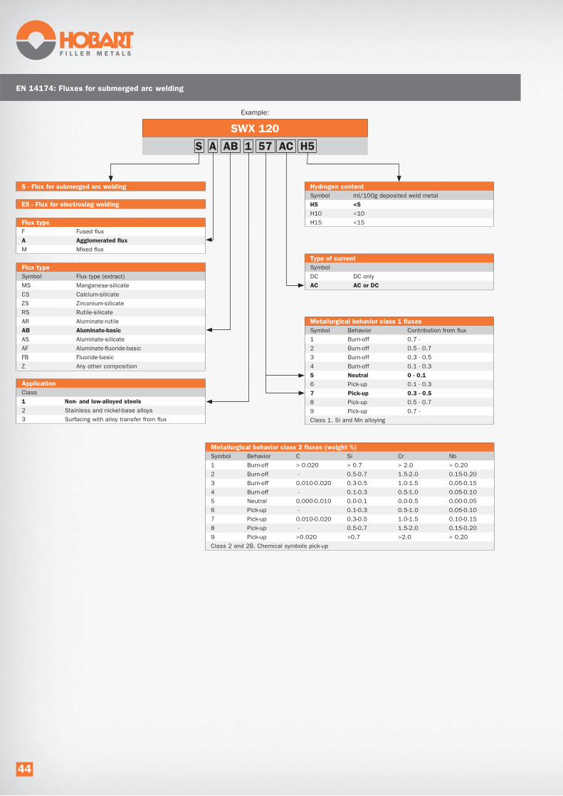
EN 14174: Fluxes for submerged arc welding
SWX 120
Example:
S - Flux for submerged arc welding
S A AB 1 57 AC H5
ES - Flux for electroslag welding
Flux type
Symbol Flux type (extract)
MS Manganese-silicate
CS Calcium-silicate
ZS Zirconium-silicate
RS Rutile-silicate
AR Aluminate-rutile
AB Aluminate-basic
AS Aluminate-silicate
AF Aluminate-fluoride-basic
FB Fluoride-basic
Z Any other composition
Flux type
F Fused flux
A Agglomerated flux
M Mixed flux
Application
Class
1 Non- and low-alloyed steels
2 Stainless and nickel-base alloys
3 Surfacing with alloy transfer from flux
Metallurgical behavior class 1 fluxes
Symbol Behavior Contribution from flux
1 Burn-off 0.7 -
2 Burn-off 0.5 - 0.7
3 Burn-off 0.3 - 0.5
4 Burn-off 0.1 - 0.3
5 Neutral 0 - 0.1
6 Pick-up 0.1 - 0.3
7 Pick-up 0.3 - 0.5
8 Pick-up 0.5 - 0.7
9 Pick-up 0.7 -
Class 1. Si and Mn alloying
Type of current
Symbol
DC DC only
AC AC or DC
Hydrogen content
Symbol ml/100g deposited weld metal
H5 <5
H10 <10
H15 <15
Metallurgical behavior class 2 fluxes (weight %)
Symbol Behavior C Si Cr Nb
1 Burn-off > 0.020 > 0.7 > 2.0 > 0.20
2 Burn-off - 0.5-0.7 1.5-2.0 0.15-0.20
3 Burn-off 0.010-0.020 0.3-0.5 1.0-1.5 0.05-0.15
4 Burn-off - 0.1-0.3 0.5-1.0 0.05-0.10
5 Neutral 0.000-0.010 0.0-0.1 0.0-0.5 0.00-0.05
6 Pick-up - 0.1-0.3 0.5-1.0 0.05-0.10
7 Pick-up 0.010-0.020 0.3-0.5 1.0-1.5 0.10-0.15
8 Pick-up - 0.5-0.7 1.5-2.0 0.15-0.20
9 Pick-up >0.020 >0.7 >2.0 > 0.20
Class 2 and 2B. Chemical symbols pick-up
44

EN ISO 14171-A: Solid wires, cored wires and wire/flux combinations
for submerged arc welding of non-alloyed and fine grain steels.
SWX 110 / SDX S2Si-EM12K
Solid wire example:
S - Flux for SAW Impact properties
Symbol Min. 47J at °C
Z
A +20
0 0
2 -20
3 -30
4 -40
5 -50
6 -60
7 -70
8 -80
9 -90
10 -100
Flux type according to EN ISO 14174
Symbol Flux type (extract)
MS Manganese-silicate
CS Calcium-silicate
ZS Zirconium-silicate
RS Rutile-silicate
AR Aluminate-rutile
AB Aluminate-basic
AS Aluminate-silicate
AF Aluminate-fluoride-basic
FB Fluoride-basic
Z Any other composition
Tensile properties
Symbol Rel/Rp0.2 min. Rm A min.
(MPa) (MPa) (%)
35 355 440-570 22
38 380 470-600 20
42 420 500-640 20
46 460 530-680 20
50 500 560-720 18
Min. tensile properties two-run technique
Symbol Parent material Welded joint
Rel/Rp0.2 (MPa) Rm (MPa)
2T 275 370
3T 355 470
4T 420 520
5T 500 500
EN ISO 14171: cored wire type and all weld metal chemical composition (%)*
Symbol Mn Ni Mo Cu
T2 1.4 0.3
T3 1.4-2.0 0.3
T2Mo 1.4 0.3-0.6 0.3
T3Mo 1.4-2.0 0.3-0.6 0.3
T2Ni1 1.4 0.6-1.2 0.3
T2Ni1.5 1.6 1.2-1.8 0.3
T2Ni2 1.4 1.8-2.6 0.3
T2Ni3 1.4 2.6-3.8 0.3
T3Ni1 1.4-2.0 0.6-1.2 0.3
T2Ni1Mo 1.4 0.6-1.2 0.3-0.6 0.3
T2Ni1Cu 1.4 0.8-1.2 0.3-0.6
* Single values are maximum.
EN ISO 14171: chemical composition solid wire (%)*
Symbol C Si Mn Mo Ni Cr Cu**
S1 0.05-0.15 0.15 0.35-0.60 0.15 0.15 0.15 0.30
S2 0.07-0.15 0.15 0.80-1.30 0.15 0.15 0.15 0.30
S3 0.07-0.15 0.15 1.30-1.75 0.15 0.15 0.15 0.30
S4 0.07-0.15 0.15 1.75-2.25 0.15 0.15 0.15 0.30
S1Si 0.07-0.15 0.15-0.40 0.35-0.60 0.15 0.15 0.15 0.30
S2Si 0.07-0.15 0.15-0.40 0.80-1.30 0.15 0.15 0.15 0.30
S2Si2 0.07-0.15 0.40-0.60 0.80-1.30 0.15 0.15 0.15 0.30
S3Si 0.07-0.15 0.15-0.40 1.30-1.85 0.15 0.15 0.15 0.30
S4Si 0.07-0.15 0.15-0.40 1.85-2.25 0.15 0.15 0.15 0.30
S1Mo 0.05-0.15 0.05-0.25 0.35-0.60 0.45-0.65 0.15 0.15 0.30
S2Mo 0.07-0.15 0.05-0.25 0.80-1.30 0.45-0.65 0.15 0.15 0.30
S2MoTiB*** 0.05-0.15 0.15-0.35 1.00-1.35 0.40-0.65 0.30
S3Mo 0.07-0.15 0.05-0.25 1.30-1.75 0.45-0.65 0.15 0.15 0.30
S4Mo 0.07-0.15 0.05-0.25 1.75-2.25 0.45-0.65 0.15 0.15 0.30
S2Ni1 0.07-0.15 0.05-0.25 0.80-1.30 0.15 0.80-1.20 0.15 0.30
S2Ni1.5 0.07-0.15 0.05-0.25 0.80-1.30 0.15 1.20-1.80 0.15 0.30
S2Ni2 0.07-0.15 0.05-0.25 0.80-1.30 0.15 1.80-2.40 0.15 0.30
S2Ni3 0.07-0.15 0.05-0.25 0.80-1.30 0.15 2.80-3.70 0.15 0.30
S2Ni1Mo 0.07-0.15 0.05-0.25 0.80-1.30 0.45-0.65 0.80-1.20 0.20 0.30
S3Ni1.5 0.07-0.15 0.05-0.25 1.30-1.70 0.15 1.20-1.80 0.20 0.30
S3Ni1Mo 0.07-0.15 0.05-0.25 1.30-1.80 0.45-0.65 0.80-1.20 0.20 0.30
S3Ni1Mo0.2 0.07-0.15 0.10-0.35 1.20-1.60 0.15-0.30 0.80-1.20 0.15 0.30
S3Ni1.5Mo 0.07-0.15 0.05-0.25 1.20-1.80 0.30-0.50 1.20-1.80 0.20 0.30
S2Ni1Cu 0.06-0.12 0.15-0.35 0.70-1.20 0.15 0.65-0.90 0.40 0.40-0.65
S3Ni1Cu 0.05-0.15 0.15-0.40 1.20-1.70 0.15 0.60-1.20 0.15 0.30-0.60
SZ Any other agreed analysis
* Single values are maximum. ** Cu, including copper layer. Al < 0.030. *** Ti: 0.10-0.20
Diffusible hydrogen in weld metal (optional)
Hydrogen content
Symbol ml/100g weld metal
H5 5
H10 10
H15 15
S 38 4 AB S2Si
45

SFA/AWS 5.17: Specification for carbon steel electrodes and fluxes for submerged arc welding
SWX 150 / SubCOR SL 731
Cored wire example:
F - Submerged arc welding flux
Tensile properties (multi-run)
Tensile strength Min. yield strength Elongation
psi (MPa) psi (MPa) %
6 60,000 - 80,000 (414 - 551) 48,000 (331) 22
7 70,000 - 95,000 (483 - 655) 58,000 (400) 22
Chemical composition for solid electrodes (%) (extract)
Classification C Mn Si S P Cu
EL8 0.10 0.25-0.60 0.07 0.030 0.030 0.35
EL8K 0.10 0.25-0.60 0.10-0.25 0.030 0.030 0.35
EL12 0.04 - 0.14 0.25 - 0.60 0.10 0.030 0.030 0.35
EM12 0.06 - 0.15 0.80 - 1.25 0.10 0.030 0.030 0.35
EM12K 0.05 - 0.15 0.80 - 1.25 0.10-0.35 0.030 0.030 0.35
EH12K 0.06 - 0.15 1.50 - 2.00 0.25-0.65 0.025 0.025 0.35
EH14 0.10 - 0.20 1.70 - 2.20 0.10 0.030 0.030 0.35
F 7 A 4 - EC1
Heat treatment
A As welded
P Post weld heat treated (PWHT) 620°C / 1h
Impact properties
Temperature Charpy-V impact min.
˚F (˚C) ft-lb (J)
0 0 (-18) 20 (27)
2 -20 (-29) 20 (27)
4 -40 (-40) 20 (27)
5 -50 (-46) 20 (27)
6 -60 (-51) 20 (27)
8 -80 (-62) 20 (27)
Z No requirements
Chemical composition for composite electrode weld metal (%)
Classification C Mn Si S P Cu
EC1 0.15 1.80 0.90 0.35 0.035 0.35
ECG Not specified
Single values are maximum
46
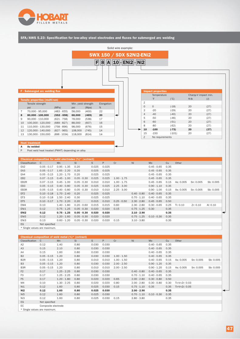
SFA/AWS 5.23: Specification for low-alloy steel electrodes and fluxes for submerged arc welding
SWX 150 / SDX S2Ni2-ENi2
Solid wire example:
F - Submerged arc welding flux
Tensile properties (multi-run)
Tensile strength Min. yield strength Elongation
psi (MPa) psi (Mpa) %
7 70,000 - 95,000 (483 - 655) 58,000 (400) 22
8 80,000 - 100,000 (552 - 698) 68,000 (469) 20
9 90,000 - 110,000 (621 - 758) 78,000 (538) 17
10 100,000 - 120,000 (689 - 827) 88,000 (607) 16
11 110,000 - 130,000 (758 - 896) 98,000 (676) 15
12 120,000 - 140,000 (827 - 965) 108,000 (745) 14
13 130,000 - 150,000 (896 - 1034) 118,000 (814) 14
Chemical composition for solid electrodes (%)* (extract)
Classification C Mn Si S P Cr Ni Mo Cu Other
EA2 0.05 - 0.17 0.95 - 1.35 0.20 0.025 0.025 0.45 - 0.65 0.35
EA3 0.05 - 0.17 1.65 - 2.20 0.20 0.025 0.025 0.45 - 0.65 0.35
EA4 0.05 - 0.15 1.20 - 1.70 0.20 0.025 0.025 0.45 - 0.65 0.35
EB2 0.07 - 0.15 0.45 - 1.00 0.05 - 0.30 0.025 0.025 1.00 - 1.75 0.45 - 0.65 0.35
EB2R 0.07 - 0.15 0.45 - 1.00 0.05 - 0.30 0.010 0.010 1.00 - 1.75 0.45 - 0.65 0.15 As: 0.005 Sn: 0.005 Sb: 0.005
EB3 0.05 - 0.15 0.40 - 0.80 0.05 - 0.30 0.025 0.025 2.25 - 3.00 0.90 - 1.10 0.35
EB3R 0.05 - 0.15 0.40 - 0.80 0.05 - 0.30 0.010 0.010 2.25 - 3.00 0.90 - 1.00 0.15 As: 0.005 Sn: 0.005 Sb: 0.005
EF2 0.10 - 0.18 1.70 - 2.40 0.20 0.025 0.025 0.40 - 0.80 0.40 - 0.65 0.35
EF3 0.10 - 0.18 1.50 - 2.40 0.30 0.025 0.025 0.70 - 1.10 0.40 - 0.65 0.35
EF5 0.10 - 0.17 1.70 - 2.20 0.20 0.015 0.010 0.25 - 0.50 2.30 - 2.80 0.45 - 0.65 0.50
EM4 0.10 1.40 - 1.80 0.20 - 0.60 0.015 0.015 0.60 2.30 - 2.80 0.30 - 0.65 0.25 Ti: 0.10 Zr: 0.10 Al: 0.10
ENi1 0.12 0.75 - 1.25 0.05 - 0.30 0.020 0.020 0.15 0.75 - 1.25 0.30 0.35
ENi2 0.12 0.75 - 1.25 0.05 - 0.30 0.020 0.020 2.10 - 2.90 0.35
ENi5 0.12 1.20 - 1.60 0.05 - 0.30 0.020 0.020 0.75 - 1.25 0.10 - 0.30 0.35
ENi3 0.13 0.60 - 1.20 0.05 - 0.30 0.020 0.020 0.15 3.10 - 3.80 0.35
EG Not specified
* Single values are maximum.
F 8 A 10 - ENi2 - Ni2
Heat treatment
A As welded
P Post weld heat treated (PWHT) depending on alloy
Impact properties
Temperature Charpy-V impact min.
˚F (˚C) ft-lb (J)
Z
0 0 (-18) 20 (27)
2 -20 (-29) 20 (27)
4 -40 (-40) 20 (27)
5 -50 (-46) 20 (27)
6 -60 (-51) 20 (27)
8 -80 (-62) 20 (27)
10 -100 (-73) 20 (27)
15 -150 (-101) 20 (27)
Z No requirements
Chemical composition of weld metal (%)* (extract)
Classification C Mn Si S P Cr Ni Mo Cu Other
A2 0.12 1.40 0.80 0.030 0.030 0.40 - 0.65 0.35
A3 0.15 2.10 0.80 0.030 0.030 0.40 - 0.65 0.35
A4 0.15 1.60 0.80 0.030 0.030 0.40 - 0.65 0.35
B2 0.05 - 0.15 1.20 0.80 0.030 0.030 1.00 - 1.50 0.40 - 0.65 0.35
B2R 0.05 - 0.15 1.20 0.80 0.010 0.010 1.00 - 1.50 0.40 - 0.65 0.15 As: 0.005 Sn: 0.005 Sb: 0.005
B3 0.05 - 0.15 1.20 0.80 0.030 0.030 2.00 - 2.50 0.90 - 1.20 0.35
B3R 0.05 - 0.15 1.20 0.80 0.010 0.010 2.00 - 2.50 0.90 - 1.20 0.15 As: 0.005 Sn: 0.005 Sb: 0.005
F2 0.17 1.25 - 2.25 0.80 0.030 0.030 0.40 - 0.80 0.40 - 0.65 0.35
F3 0.17 1.25 - 2.25 0.80 0.030 0.030 0.70 - 1.10 0.40 - 0.65 0.35
F5 0.17 1.20 - 1.80 0.80 0.020 0.020 0.65 2.00 - 2.80 0.30 - 0.80 0.50
M4 0.10 1.30 - 2.25 0.80 0.020 0.020 0.80 2.00 - 2.80 0.30 - 0.80 0.30 Ti+V+Zr: 0.03
Ni1 0.12 1.60 0.80 0.025 0.030 0.15 0.75 - 1.10 0.35 0.35 Ti+V+Zr: 0.05
Ni2 0.12 1.60 0.80 0.025 0.030 2.00 - 2.90 0.35
Ni5 0.12 1.60 0.80 0.025 0.030 0.70 - 1.10 0.10 - 0.30 0.35
Ni3 0.12 1.60 0.80 0.025 0.030 0.15 2.80 - 3.80 0.35
EG Not specified
EC Composite electrode
* Single values are maximum.
47

EN ISO 24598-A: Solid wire electrodes, tubular cored electrodes and
electrode-flux combinations for submerged arc welding of creep resisting steels
SWX 150 / SDX CrMo1-EB2R
Solid wire example:
S - Submerged arc welding process
S S CrMo1 FB
Chemical composition all weld metal for flux / (cored) wire combinations
Symbol C Si Mn P S Cr Ni Mo Cu V Other
Mo 0.15 0.80 1.4 0.030 0.030 0.2 0.3 0.40 - 0.65 0.35 0.03 Nb: 0.01
MnMo 0.15 0.80 2.0 0.030 0.030 0.2 0.3 0.40 - 0.65 0.35 0.03 Nb: 0.01
MoV 0.15 0.80 1.4 0.030 0.030 0.20 - 0.60 0.3 0.45 - 1.00 0.35 0.20 - 0.45 Nb: 0.01
CrMo1 0.15 0.80 1.20 0.030 0.030 0.80 - 1.30 0.25 0.35 - 0.65 0.40 0.03 Nb: 0.01
CrMoV1 0.15 0.80 1.40 0.030 0.030 0.80 - 1.30 0.3 0.80 - 1.30 0.35 0.10 - 0.35 Nb: 0.01
CrMo2 0.15 0.80 1.20 0.030 0.030 2.0 - 2.8 0.3 0.80 - 1.50 0.35 0.03 Nb: 0.01
CrMo2Mn 0.10 0.80 1.40 0.030 0.020 1.8 - 2.5 0.3 0.80 - 1.20 0.35 0.03 Nb: 0.01
CrMo2L 0.05 0.80 1.20 0.030 0.030 2.0 - 2.8 0.3 0.80 - 1.15 0.35 0.03 Nb: 0.01
CrMo5 0.10 0.80 1.20 0.030 0.030 4.50 - 6.50 0.3 0.45 - 0.80 0.35 0.03 Nb: 0.01
CrMo9 0.10 0.80 1.20 0.030 0.030 8.0 - 10.0 1.0 0.70 - 1.20 0.35 0.15 Nb: 0.01
CrMo91 0.15 0.80 1.80 0.030 0.030 8.0 - 10.5 1.0 0.70 - 1.20 0.35 0.10 - 0.30 Nb: 0.02 - 0.10
CrMoWV12 0.24 0.80 1.4 0.030 0.030 9.5 - 12.0 0.80 0.70 - 1.20 0.35 0.15 - 0.40 Nb: 0.01
Z Any other agreed composition
* Single values are maximum.
Mechanical properties all weld metal flux / (cored) wire combinations
Symbol min. yield Tensile Elongation CVN impact toughness at +20°C Heat treatment
strength strength Av. of 3 min. Min. single value Preheat and interpass Post weld heat Time
MPa MPa % J J temperature ˚C treatment ˚C min.
Mo / MnMo 355 510 22 47 38 <200
MoV 355 510 18 47 38 200-300 690-730 60
CrMo1 355 510 20 47 38 150-250 660-700 60
CrMoV1 435 590 15 24 21 200-300 680-730 60
CrMo2/CrMo2Mn 400 500 18 47 38 200-300 690-750 60
CrMo2L 400 500 18 47 38 200-300 690-750 60
CrMo5 400 590 17 47 38 200-300 730-760 60
CrMo9 435 590 18 34 27 200-300 740-780 120
CrMo91 415 585 17 47 38 250-350 750-760 180
CrMoWV12 550 690 15 34 27 250-350 or 400-500 740-780 120
S - Solid wire T - Cored wire
Flux type according to EN ISO 14174
Symbol Flux type
MS Manganese-silicate
CS Calcium-silicate
ZS Zirconium-silicate
RS Rutile-silicate
AR Aluminate-rutile
AB Aluminate-basic
AS Aluminate-silicate
AF Aluminate-fluoride-basic
FB Fluoride-basic
Z Any other composition
48

ISO 26304-A: Solid wire electrodes, tubular cored electrodes and
electrode-flux combinations for submerged arc welding of high strength steels
SWX 150 / SubCOR SL 742
Cored wire example:
S - Submerged arc welding Impact properties
Symbol Min. 47J at °C
Z No requirement
A +20
0 0
2 -20
3 -30
4 -40
5 -50
6 -60
Flux type according to EN ISO 14174
Symbol Flux type
MS Manganese-silicate
CS Calcium-silicate
ZS Zirconium-silicate
RS Rutile-silicate
AR Aluminate-rutile
AB Aluminate-basic
AS Aluminate-silicate
AF Aluminate-fluoride-basic
FB Fluoride-basic
Z Any other composition
Tensile properties
Symbol Rel/Rp0.2 min. Rm A min.
MPa MPa %
55 550 640-820 18
62 620 700-890 18
69 690 770-940 17
79 790 880-1080 16
89 890 940-1180 15
Chemical composition wire (%)*
Symbol C Si Mn P S Cr Ni Mo Cu Other
S2Ni1Mo 0.07 - 0.15 0.05 - 0.25 0.80 - 1.30 0.020 0.020 0.20 0.80 - 1.20 0.45 - 0.65 0.30
S3Ni1Mo 0.07 - 0.15 0.05 - 0.35 1.30 - 1.80 0.020 0.020 0.20 0.80 - 1.20 0.45 - 0.65 0.30 0.50
S3Ni1.5Mo 0.07 - 0.15 0.05 - 0.25 1.20 - 1.80 0.020 0.020 0.20 1.20 - 1.80 0.30 - 0.50 0.30 0.50
S2Ni2Mo 0.05 - 0.09 0.15 1.10 - 1.40 0.015 0.015 0.15 2.00 - 2.50 0.45 - 0.60 0.30 0.50
S2Ni3Mo 0.08 - 0.12 0.10 - 0.25 0.80 - 1.20 0.020 0.020 0.15 2.80 - 3.20 0.10 - 0.25 0.30 0.50
S3Ni1.5CrMo 0.07 - 0.14 0.05 - 0.15 1.30 - 1.50 0.020 0.020 0.15 - 0.35 1.50 - 1.70 0.30 - 0.50 0.30 0.50
S3Ni2.5CrMo 0.07 - 0.15 0.10 - 0.25 1.20 - 1.80 0.020 0.020 0.30 - 0.85 2.00 - 2.60 0.40 - 0.70 0.30 0.50
S1Ni2.5CrMo 0.07 - 0.15 0.10 - 0.25 0.45 - 0.75 0.020 0.020 0.50 - 0.85 2.10 - 2.60 0.40 - 0.70 0.30 0.50
S4Ni2CrMo 0.08 - 0.11 0.30 - 0.40 1.80 - 2.00 0.015 0.15 0.85 - 1.00 2.10 - 2.60 0.55 - 0.70 0.30 0.50
TZ Any other agreed analyses
* Single values are maximum.
Diffusible hydrogen in weld metal (optional)
Hydrogen content
Symbol ml/100g weld metal
H5 5
H10 10
H15 15
S 69 6 FB T3 Ni2.5CrMo
All weld metal chemical composition flux / cored wire combination (%)*
Symbol C Si Mn P S Cr Ni Mo V
T3NiMo 0.05 - 0.12 0.20 - 0.60 1.30 - 1.90 0.02 0.02 0.60 - 1.00 0.15 - 0.45
T3Ni1Mo 0.03 - 0.09 0.10 - 0.50 1.39 - 1.80 0.02 0.02 1.00 - 1.50 0.45 - 0.65
T3Ni2MoV 0.03 - 0.09 0.20 1.20 - 1.70 0.02 0.02 1.60 - 2.00 0.20 - 0.50 0.05 - 0.15
T3Ni2Mo 0.03 - 0.09 0.40 - 0.80 1.30 - 1.80 0.02 0.02 1.80 - 2.40 0.20 - 0.40
T3Ni3Mo 0.03 - 0.09 0.20 - 0.70 1.60 - 2.10 0.02 0.02 2.70 - 3.20 0.20 - 0.40
T3Ni2.5CrMo 0.03 - 0.09 0.10 - 0.50 1.20 - 1.70 0.02 0.02 0.40 - 0.70 2.20 - 2.60 0.30 - 0.60
T3Ni2.5Cr1Mo 0.04 - 0.10 0.20 - 0.70 1.20 - 1.70 0.02 0.02 0.70 - 1.20 2.20 - 2.60 0.40 - 0.70
TZ Any other agreed analyses
* Single values are maximum.
49
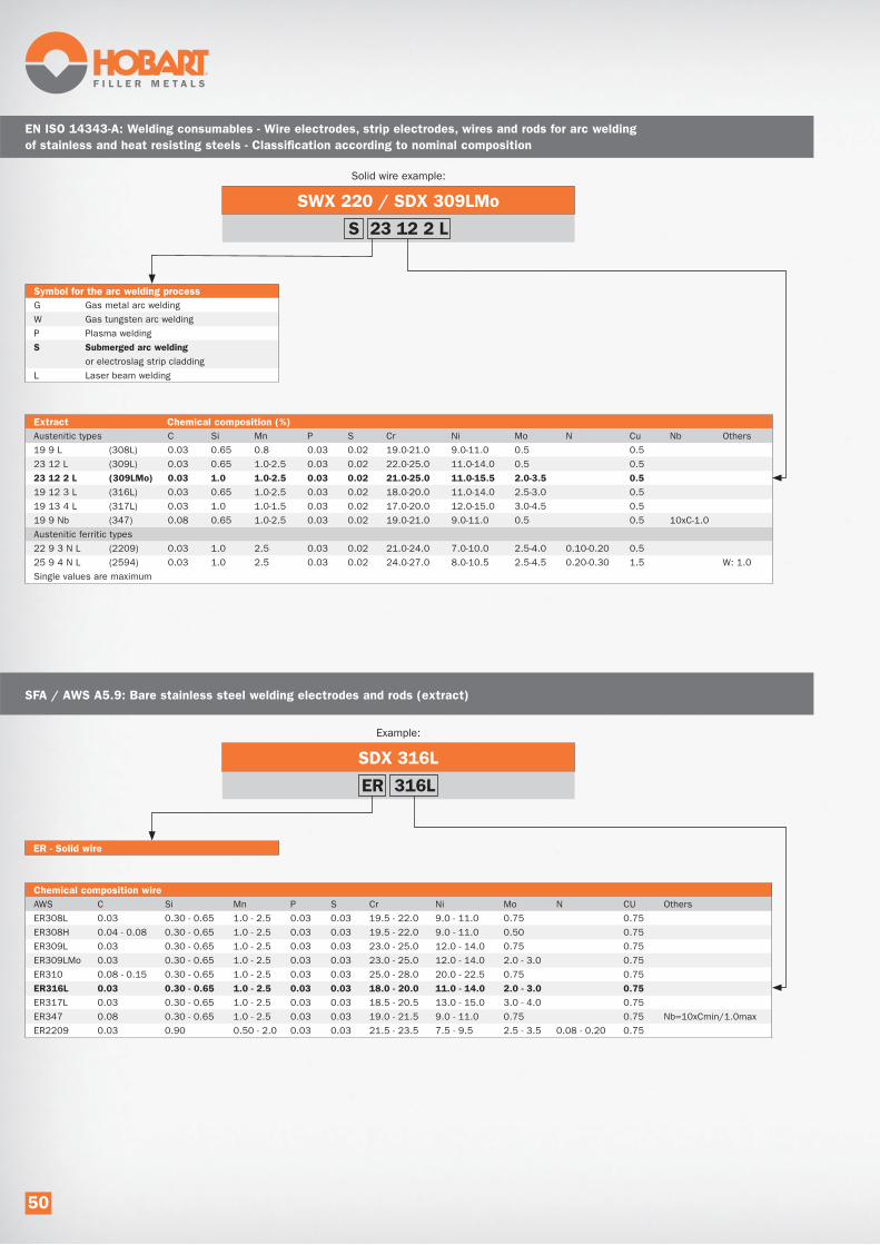
SWX 220 / SDX 309LMo
Solid wire example:
Extract Chemical composition (%)
Austenitic types C Si Mn P S Cr Ni Mo N Cu Nb Others
19 9 L (308L) 0.03 0.65 0.8 0.03 0.02 19.0-21.0 9.0-11.0 0.5 0.5
23 12 L (309L) 0.03 0.65 1.0-2.5 0.03 0.02 22.0-25.0 11.0-14.0 0.5 0.5
23 12 2 L (309LMo) 0.03 1.0 1.0-2.5 0.03 0.02 21.0-25.0 11.0-15.5 2.0-3.5 0.5
19 12 3 L (316L) 0.03 0.65 1.0-2.5 0.03 0.02 18.0-20.0 11.0-14.0 2.5-3.0 0.5
19 13 4 L (317L) 0.03 1.0 1.0-1.5 0.03 0.02 17.0-20.0 12.0-15.0 3.0-4.5 0.5
19 9 Nb (347) 0.08 0.65 1.0-2.5 0.03 0.02 19.0-21.0 9.0-11.0 0.5 0.5 10xC-1.0
Austenitic ferritic types
22 9 3 N L (2209) 0.03 1.0 2.5 0.03 0.02 21.0-24.0 7.0-10.0 2.5-4.0 0.10-0.20 0.5
25 9 4 N L (2594) 0.03 1.0 2.5 0.03 0.02 24.0-27.0 8.0-10.5 2.5-4.5 0.20-0.30 1.5 W: 1.0
Single values are maximum
S 23 12 2 L
EN ISO 14343-A: Welding consumables - Wire electrodes, strip electrodes, wires and rods for arc welding
of stainless and heat resisting steels - Classification according to nominal composition
SDX 316L
Example:
ER - Solid wire
Chemical composition wire
AWS C Si Mn P S Cr Ni Mo N CU Others
ER308L 0.03 0.30 - 0.65 1.0 - 2.5 0.03 0.03 19.5 - 22.0 9.0 - 11.0 0.75 0.75
ER308H 0.04 - 0.08 0.30 - 0.65 1.0 - 2.5 0.03 0.03 19.5 - 22.0 9.0 - 11.0 0.50 0.75
ER309L 0.03 0.30 - 0.65 1.0 - 2.5 0.03 0.03 23.0 - 25.0 12.0 - 14.0 0.75 0.75
ER309LMo 0.03 0.30 - 0.65 1.0 - 2.5 0.03 0.03 23.0 - 25.0 12.0 - 14.0 2.0 - 3.0 0.75
ER310 0.08 - 0.15 0.30 - 0.65 1.0 - 2.5 0.03 0.03 25.0 - 28.0 20.0 - 22.5 0.75 0.75
ER316L 0.03 0.30 - 0.65 1.0 - 2.5 0.03 0.03 18.0 - 20.0 11.0 - 14.0 2.0 - 3.0 0.75
ER317L 0.03 0.30 - 0.65 1.0 - 2.5 0.03 0.03 18.5 - 20.5 13.0 - 15.0 3.0 - 4.0 0.75
ER347 0.08 0.30 - 0.65 1.0 - 2.5 0.03 0.03 19.0 - 21.5 9.0 - 11.0 0.75 0.75 Nb=10xCmin/1.0max
ER2209 0.03 0.90 0.50 - 2.0 0.03 0.03 21.5 - 23.5 7.5 - 9.5 2.5 - 3.5 0.08 - 0.20 0.75
ER 316L
SFA / AWS A5.9: Bare stainless steel welding electrodes and rods (extract)
Symbol for the arc welding process
G Gas metal arc welding
W Gas tungsten arc welding
P Plasma welding
S Submerged arc welding
or electroslag strip cladding
L Laser beam welding
50
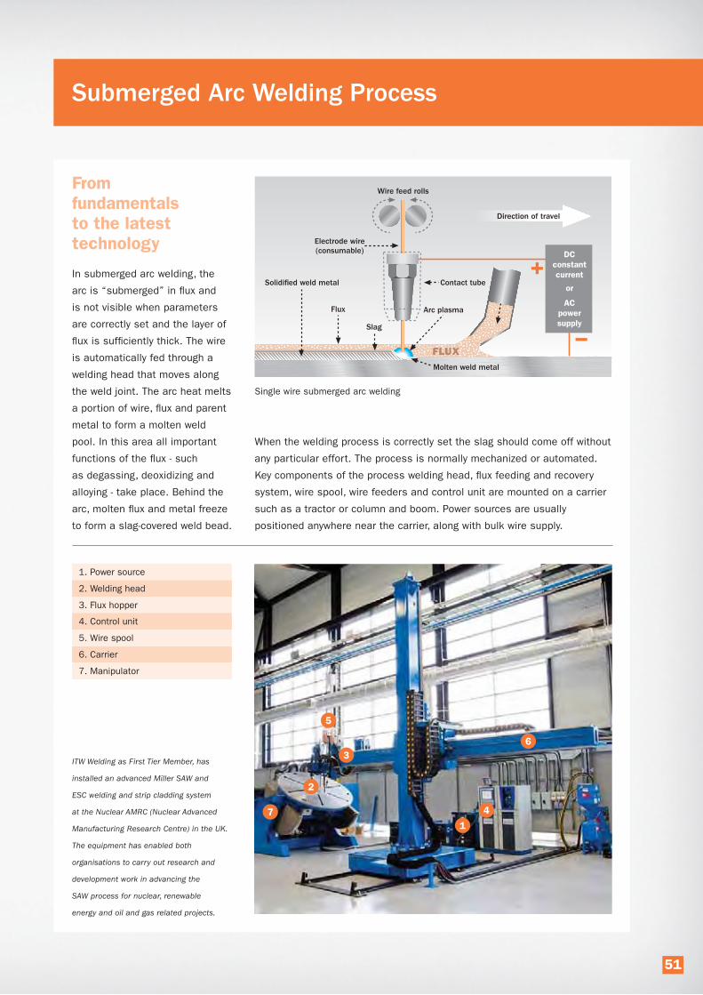
Submerged Arc Welding Process
Single wire submerged arc welding
From fundamentals to the latest technology
In submerged arc welding, the
arc is “submerged” in flux and
is not visible when parameters
are correctly set and the layer of
flux is sufficiently thick. The wire
is automatically fed through a
welding head that moves along
the weld joint. The arc heat melts
a portion of wire, flux and parent
metal to form a molten weld
pool. In this area all important
functions of the flux - such
as degassing, deoxidizing and
alloying - take place. Behind the
arc, molten flux and metal freeze
to form a slag-covered weld bead.
1. Power source
2. Welding head
3. Flux hopper
4. Control unit
5. Wire spool
6. Carrier
7. Manipulator
When the welding process is correctly set the slag should come off without
any particular effort. The process is normally mechanized or automated.
Key components of the process welding head, flux feeding and recovery
system, wire spool, wire feeders and control unit are mounted on a carrier
such as a tractor or column and boom. Power sources are usually
positioned anywhere near the carrier, along with bulk wire supply.
6
1
2
4
5
3ITW Welding as First Tier Member, has
installed an advanced Miller SAW and
ESC welding and strip cladding system
at the Nuclear AMRC (Nuclear Advanced
Manufacturing Research Centre) in the UK.
The equipment has enabled both
organisations to carry out research and
development work in advancing the
SAW process for nuclear, renewable
energy and oil and gas related projects.
7
51

Submerged Arc Welding Process
Pros and cons of the process
Submerged arc welding has a number of distinct
advantages in terms of welding economy and weld quality,
but also some limitations compared with other arc
welding processes.
Advantages:
• Clean automatic process without UV radiation
and spatter and minimal fume.
• Superior deposition rates of up to 100 kg/h
(220 lbs/h) in multiple-wire welding.
• Very high travel speeds of up to 250 cm/min (100”/min).
• From a few millimetres to unlimited plate thickness.
• Excellent mechanical properties and X-ray quality
welds.
• No spatter - high weld metal recovery.
• Reliable process with secure weld penetration and
reduced risk of lack of fusion.
• Weld metal chemical composition and mechanical
properties can be controlled via the flux/wire
combination.
Limitations:
• Capital investment.
• Only suited for flat and horizontal fillet positions
(PA/1G, PB/2F). PC/2G possible with flux support.
• Requires first class joint preparation.
• Requires precise parameter setting and positioning
of the wire electrode.
• Adjustments not easily determined because of
the invisible arc.
• Requires disposal of the slag.
Welding flux - A critical process component
In submerged arc welding, the flux performs a number
of essential functions, enabling a stable arc at the high
welding currents characteristic for this productive process:
• Creation of a slag that forms a cavity for the arc
to establish in.
• Improvement of arc conductivity and droplet transfer.
• Shielding droplets, weld pool and solidifying weld
from the surrounding air.
• Deoxidization of the weld metal and removal of
impurities.
• Supports deep penetration by preventing heat to
escape.
• Meets different chemical and mechanical weld
requirements, depending on the wire electrode.
To enhance the submerged arc welding
process the flux must:
• have the right particle mix to allow degassing
and facilitate high welding currents.
• have the right slag properties to allow high travel
speeds.
• create a slag that releases easily.
• provide the lowest possible flux consumption.
• have good grain strength to limit the forming
of dust in recycling.
52

Submerged arc welding fluxes
and manufacturing methods
There are basically two types of welding fluxes
characterized by their manufacturing method;
agglomerated and fused.
Fused fluxes have long been used universally in
submerged arc welding, but have widely been
replaced by agglomerated fluxes – even in countries
with a tradition in the use of fused fluxes.
In the production of agglomerated fluxes, powder raw
materials with specified grain size are mixed with a
bonding agent to form chemically homogeneous grains.
Subsequently, the flux is baked at high temperature to
remove moisture and sieved to the desired grain size
distribution. Agglomerated fluxes provide the following
advantages compared to fused fluxes to the submerged
arc welding process:
• The lower temperature in the manufacturing process
allows addition of a higher level of deoxidizers and
alloying elements. This results in cleaner welds with
significantly improved mechanical properties; most
notably with better low-temperature impact toughness.
• In the vast majority of applications agglomerated fluxes
allow higher travelling speed, typically meaning lower
manufacturing costs.
• Agglomerated fluxes are available for all steel grades
and applications.
• Lower flux consumption due to lower arc voltage.
Hydrogen classes
The hydrogen class of a flux, as manufactured, is
embedded in the classification according to EN ISO
14174, AWS A5.17 and AWS A5.23.
EN ISO 14174: e.g. S A AB 1 67 AC H5. H5 indicates
that the flux is capable of producing a weld metal with less
than 5 ml diffusible hydrogen per 100 g weld metal.
AWS A5.17: e.g. F7A4-EM12K-H4. H4 indicates that the
flux is capable of producing a weld metal with less than
4 ml diffusible hydrogen per 100 g weld metal.
Hydrogen class ml/100 g
deposited
weld metalEN ISO 14174 AWS A5.17 and AWS A5.23
H2 <2
H4 <4
H5 <5
H8 <8
H10 <10
H15 <15
H16 <16
Flux types and standards
Submerged arc welding fluxes and flux/wire combina-
tions are named, standardized and categorized in various
European/international (EN ISO) and United States (AWS)
standards. The standards referred to in this catalogue are:
• EN ISO 14171:
Solid wire electrodes, tubular cored electrodes and
electrode/flux combinations for submerged arc welding
of non-alloy and fine grain steels.
• EN ISO 14174:
Fluxes for submerged arc welding.
• EN ISO 24598:
Solid wire electrodes, tubular cored electrodes and
electrode-flux combinations for submerged arc welding
of creep resisting steels.
>>
Hobart fluxes and packaging
The Hobart welding fluxes reviewed in this catalogue
are all agglomerated, low-hydrogen types. The various
SWX fluxes, in combination with the appropriate SDX or
SubCOR wire electrode, cover a wide range of grades
within normal strength, high strength, low-temperature,
creep resistant and stainless steel, as well as nickel base
alloys. They feature extremely low moisture contents and
are all supplied standard in moisture proof EAE (Excess
Air Evacuation) bags or DoubleBag bulk packaging, both
giving maximum security against moisture absorption and
hydrogen cracking.
53

Submerged Arc Welding Process
Symbol Flux type Characteristic chemical constituents % of total flux
FB Fluoride-basic CaO+MgO+CaF2+MnO >50
SiO2
<20
CaF2
>15
AF Aluminate-fluoride-basic Al2O
3 + CaF
2>70
AB Aluminate-basic Al2O
3 + CaO + MgO >40
Al2O
3>20
CaF2
<22
AR Aluminate-rutile Al2O
3 + TiO
2>40
Flux basicity index (BI)
Basicity is commonly used to describe the relation between basic flux ingredients and acidic flux ingredients.
BI= % basic oxides
% acidic oxides
The most commonly applied method to calculate the basicity index is according to Boniszewski’s formula:
BI= CaO + MgO+SrO+BaO+Li2O+Na2O+K2O+CaF2+0.5 (FeO+MnO)
SiO2+0.5 (Al
2O3+TiO
2+ZrO
2)
A high basicity index leads to lower oxygen levels and thereby to fewer micro inclusions in the weld metal, which is
beneficial for the microstructure and improves impact toughness. However, a higher basicity generally gives a slag
with lower viscosity and hence a lower current carrying capacity of the flux, leading to lower productivity.
It is recommended to look for the lowest possible basicity flux in order to achieve the required impact toughness.
Basicity index Type of flux Weld metal O content (wt.-%)
BI < 0.9 Low basicity flux > 700 ppm
BI 0.9-1.2 Neutral basicity flux 500 – 700 ppm
BI 1.2-2.5 Basic flux 350 – 500 ppm
BI >2.5 High basic flux <350 ppm
Fluxes are categorized in different ways. Agglomerated
versus fused fluxes is one of them, but within these
categories there is a variety of flux compositions possible.
A refined method is given in the EN ISO 14174 flux
classification standard where fluxes are marked with a
symbol for their main chemical constituents, for example:
S A AB 1 67 AC H5
Here AB signifies that it is an aluminate-basic flux.
The most frequently used symbols are given in the
following table together with their main chemical
constituents. All relevant EN ISO standards use these
symbols to typify the flux within classifications of flux/wire
combinations. All relevant classification standards are
explained in detail elsewhere in this catalogue.
• EN ISO 26304:
Solid wire electrodes, tubular cored electrodes and
electrode-flux combinations for submerged arc welding
of high strength steels.
• EN ISO 14343:
Wire electrodes, strip electrodes, wires and rods for
arc welding of stainless and heat resisting steels.
• SFA/AWS 5.17:
Specification for carbon steel electrodes and fluxes
for submerged arc welding.
• SFA/AWS 5.23:
Specification for low-alloy steel electrodes and fluxes
for submerged arc welding.
• SFA/AWS A5.9:
Bare stainless steel welding electrodes and rods.
54
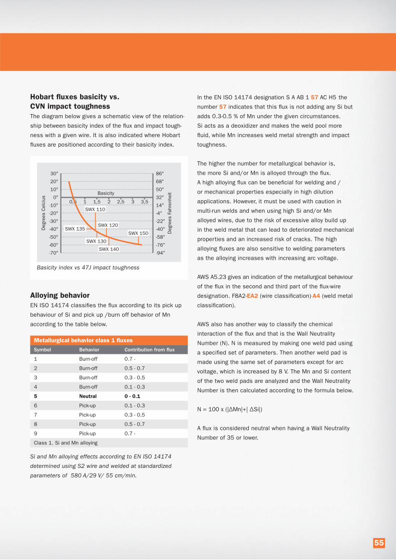
Hobart fluxes basicity vs.
CVN impact toughness
The diagram below gives a schematic view of the relation-
ship between basicity index of the flux and impact tough-
ness with a given wire. It is also indicated where Hobart
fluxes are positioned according to their basicity index.
Basicity index vs 47J impact toughness
Alloying behavior
EN ISO 14174 classifies the flux according to its pick up
behaviour of Si and pick up /burn off behavior of Mn
according to the table below.
Metallurgical behavior class 1 fluxes
Symbol Behavior Contribution from flux
1 Burn-off 0.7 -
2 Burn-off 0.5 - 0.7
3 Burn-off 0.3 - 0.5
4 Burn-off 0.1 - 0.3
5 Neutral 0 - 0.1
6 Pick-up 0.1 - 0.3
7 Pick-up 0.3 - 0.5
8 Pick-up 0.5 - 0.7
9 Pick-up 0.7 -
Class 1. Si and Mn alloying
Si and Mn alloying effects according to EN ISO 14174
determined using S2 wire and welded at standardized
parameters of 580 A/29 V/ 55 cm/min.
In the EN ISO 14174 designation S A AB 1 57 AC H5 the
number 57 indicates that this flux is not adding any Si but
adds 0.3-0.5 % of Mn under the given circumstances.
Si acts as a deoxidizer and makes the weld pool more
fluid, while Mn increases weld metal strength and impact
toughness.
The higher the number for metallurgical behavior is,
the more Si and/or Mn is alloyed through the flux.
A high alloying flux can be beneficial for welding and /
or mechanical properties especially in high dilution
applications. However, it must be used with caution in
multi-run welds and when using high Si and/or Mn
alloyed wires, due to the risk of excessive alloy build up
in the weld metal that can lead to deteriorated mechanical
properties and an increased risk of cracks. The high
alloying fluxes are also sensitive to welding parameters
as the alloying increases with increasing arc voltage.
AWS A5.23 gives an indication of the metallurgical behaviour
of the flux in the second and third part of the flux-wire
designation. F8A2-EA2 (wire classification)-A4 (weld metal
classification).
AWS also has another way to classify the chemical
interaction of the flux and that is the Wall Neutrality
Number (N). N is measured by making one weld pad using
a specified set of parameters. Then another weld pad is
made using the same set of parameters except for arc
voltage, which is increased by 8 V. The Mn and Si content
of the two weld pads are analyzed and the Wall Neutrality
Number is then calculated according to the formula below.
N = 100 x (|ΔMn|+| ΔSi|)
A flux is considered neutral when having a Wall Neutrality
Number of 35 or lower.
55

Submerged Arc Welding Process
Hobart metallurgical behavior diagrams
For each flux Hobart gives the appropriate classification
according to EN ISO 14174 with the two digit identification
of metallurgical behaviour. In addition, diagrams are
provided to show the typical weld metal analyses in
relation to the wire analyses for silicon and manganese.
Values are determined at both 500 and 800 A to provide
guidance.
1.2
1.0
0.8
0.6
0.4
0.2
0.00.00 0.05 0.10 0.15 0.20 0.25 0.30
2.4
2.0
1.6
1.2
0.8
0.4
0.0 0.0 0.5 1.0 1.5 2.0
500 A
800 A
% Si in wire
% Mn in wire
% Si in weld metal
500 A
800 A
% Mn in weld metal
Metallurgical behavior diagram for flux SWX 110,
a slightly Si and Mn alloying flux.
Alloying fluxes
Alloying fluxes add chromium, nickel and/or molybdenum
to obtain a specific high alloy weld metal composition
when using lower alloyed wires or strips.
Voltage control is important, as it has an influence on
the amount of flux taking part in the chemical reaction.
Alloying fluxes are mostly applied in stainless and high
alloy cladding applications.
Grain size
Flux grain size is important because it influences current
carrying capacity and flux feeding and recovery:
• A correct grain size allows gases to escape from
the molten weld pool.
• Grain size determines the current carrying capacity
of the flux. Coarser particle size is needed for higher
currents.
• For high travel speeds in thin materials a fine-grained
flux is preferred.
• Fluxes with excessive high amounts of fine particles
could segregate in flux feeding and recovery systems.
Grain size is commonly expressed by a minimum and
maximum particle size. The grain size can be expressed
either in mm (size of the openings in the sieve cloth in
mm) or in mesh (the number of openings/inch in the
sieve cloth)
A grain size of 0.2-1.6 mm means that the grains of the
flux are larger than 0.2 mm (~65 mesh) and smaller than
1.6 mm (~12 mesh).
A grain size of 12-65 mesh means that the grains of the
flux are smaller than 12 mesh (~1.6 mm) and
larger than 65 mesh (~0.2 mm).
Hobart states grain size in both millimeters and mesh
in product data.
Submerged arc welding process options
Submerged arc welding even in its simplest form is
already a highly productive process. Deposition rates in
single wire welding, the most widely applied method, can
amount to 12 lbs/h when applications allow the use of
large diameter wires at high welding currents. A variety
of process options has evolved over the years with the
objective to further increase the welding productivity; often
developed to meet the challenges of specific industries.
The following process options are observed in today’s
submerged arc welding.
Single wire SAW
· One wire, one feeder, one welding head
· One power source, one control unit
· Wire diameter 1.6-5.0 mm (1/16” - 3/16”)
· Welding current 200-1000 A
· Generally applied across industries
Deposition rate up to 12 kg/h (26 lbs/h)
56

Twin wire SAW
· Two wires, one 2-rolls wire feeder, one 2-wire contact nozzle
· One power source, one control unit
· Wire diameter 1.2-3.2 mm (0.045”-1/8”)
· Total welding current 400-1200 A
· Generally applied across industries
· Moderate investment to upgrade from single wire SAW
Deposition rate up to 20 kg/h (44 lbs/h)
Tandem wire SAW
· Two wires, two feeders, two welding torches
· Two power sources, two control units
· Wire diameter 3.2-5.0 mm (1/8”-3/16”)
· Total welding current 1200-2000 A
· Shipbuilding, pressure vessels, heavy beams, bridges, offshore fab.
· Relatively high investment compared to single wire SAW
Deposition rate up to 25 kg/h (55 lbs/h)
Tandem single-twin wire SAW
· 3 wires, one 1-roll feeder, one 2- roll feeder, one 1-wire head, one 2-wire head.
· Two power sources, two control units
· Wire diameter 2.4-4.0 mm (3/32”-5/32”)
· Total welding current 1100-1700 A
· Wind towers, pressure vessels
· Small incremental investment compared to Tandem SAW
Deposition rate up to 30 kg/h (66 lbs/h)
Tandem twin wire SAW
· 4 wires, two 2-rolls feeders, two 2-wire heads
· Two power sources, two control units
· Wire diameters 1.6-3.2 mm (1/16”-1/8”)
· Total welding current 1500-2200 A
· Wind towers, pressure vessels
· Small incremental investment compared to Tandem SAW
Deposition rate up to 35 kg/h (77 lbs/h)
Multi wire SAW
· Up to five wires, feeders, heads, power sources and control units
· Wire diameters 3.2-5.0 mm (1/8”-3/16”)
· Total welding current 2000-5500 A
· Pipemills, offshore, shipbuilding.
· High investment
Deposition rate up to 125 kg/h with five wires (220 lbs/h)
57

Submerged Arc Welding Process
Effects of welding parameters
The welding parameters in submerged arc welding - arc
voltage, welding current, travel speed, stick-out, torch angle,
wire diameter, wire feed speed and polarity - all influence
the shape and quality of the weld, and productivity.
It is important to be aware of their individual and
combined influence. In this chapter we do not discuss
welding defects that result from incorrect parameters –
mostly set too low or too high. These are discussed in the
trouble shooting section of this catalog. The table reviews
the effects when individual welding parameters are in-
creased, while all other parameters remain unchanged.
Decreasing them will have opposite effects.
Effects of increased current Effects on weld profile
Higher deposition rate
Higher heat input
Larger heat affected zone
Increased penetration
Increased bead height
Higher dilution with parent metal
Effects of increased voltage Effects on weld profile
Higher heat input
Larger heat affected zone
No change of penetration
Wider beads, lower bead height
Increased flux consumption
Effects of increased travel speed Effects on weld profile
Lower heat input
Smaller beads
Less penetration
Less dilution
Effects of increased stick-out Effects on weld profile
Higher deposition rate
Less penetration
Higher bead
Lower arc voltage
Effects of increased wire diameter Effects on weld profile
Possibility of increased deposition rate
Less penetration
Wider bead
350 A 500 A 650 A
24 V 27 V 31 V
38 cm/min
15”/min
76 cm/min
30”/min
100 cm/min
40”/min
15 mm - 0.6” 25 mm - 1” 35 mm - 1.6”
3.2 mm - 1/8”
electrode
4 mm - 5/32”
electrode
5 mm - 3/16”
electrode
58

Effects of type of current and polarity Effects on weld profile
DC+
Deepest penetration
Highest dilution
Lowest deposition rate
AC
Lower penetration
Lower dilution
Higher deposition rate than DC+
DC-
Higher deposition rate than AC
Lowest dilution
Lowest penetration
Mainly used for cladding
DC+ AC DC-
Penetration:
Reinforcement:
Risk of hot cracking:
Deep
Maximum
High
Moderate
Moderate
Low
Shallow
Minimum
Low
Pulling Neutral
Pushing
Effects of electrode angle in butt welds
Max. penetration
Slow travel speed
Less penetration
Higher travel speed
Least penetration
Highest travel speed
Welding direction
59

Submerged Arc Power Sources
The performance of power sources is essential in
mechanized or fully automated submerged arc welding,
where they are often subjected to high duty cycles at high
welding currents. A power source needs to be able to oper-
ate at welding currents as low as 300 A for thin materials
and over 1000 A for thick materials, at up to 100% duty
cycle. Robustness and durability are primary requirements,
along with advanced electronic submerged arc functionality
giving full control over the arc and its effects on the weld.
Power source characteristics
Constant current (CC) and constant voltage (CV) are
two important principles. They used to be applied in
separate submerged arc power source types, but are
nowadays available in a single machine and can be
switched on and off when needed.
A CC characteristic shows a relatively steep downward
slope in the volt/ampere curve. The welding current is the
primary parameter set on the machine. Fluctuations in arc
length/arc voltage (ΔV) - which are inevitable during welding
- will only cause small variations in amperage (ΔA).
To obtain a stable process, arc voltage sensing wire feed-
ers constantly adapt the wire feed speed to maintain the
Feature CC CV
Open circuit voltage 60-80 V 25-55 V
Parameter setting By welding current By arc voltage
Polarity AC / DC AC / DC
Arc stability Fluctuations Stable
Arc regulation Through wire feed speed Self-regulating
Application (best practice) Larger diameter wires Smaller and larger diameter wires
The table summarises the most important features of CC and CV applied in subarc power sources.
Output characteristics: CC & CV
CV Characteristic
In CV a small ΔV causes
a relative large ΔA
CC Characteristic
In CC a small ΔA causes
a relative large ΔV
welding current at the set value. CC is best applicable with
larger diameter wires fed at comparatively low wire feed
speeds, because this places lower demands on the wire
feed speed range and acceleration of the motors. However,
with today’s (tacho controlled) wire feed motors, CC can be
applied with smaller diameter wires as well. The constant
current provides stable and dependable weld penetration
when welding materials with medium or high wall thickness.
A CV characteristic allows the use of thin welding wires
while maintaining a stable arc. The volt/ampere curve
is relatively flat. The arc voltage is the primary parameter
set on the power source. Small fluctuations in arc voltage
(ΔV) will cause relatively big changes in amperage (ΔA),
while the wire feed speed remains the same. A higher
voltage gives lower amperage and consequently a lower
melt-off rate of the wire. A lower voltage gives higher
amperage and accelerated wire melt-off. In this
self-regulating way, the process balances around the
set voltage/arc length.
CV can be applied with all wire diameters, but performs
best below Ø 2.4 mm (3/32”), due to the self-regulating
effect. It is best suited for welding thin materials up to
12 mm (1/2”) and for strip cladding. The constant voltage
gives straight welds with constant bead width.
Making use of polarity
As listed under ”Effects of welding parameters” polarity
has an effect on penetration, deposition, dilution, heat
input and arc stability. Use of this is being made in
different SAW processes and process variants.
DC+ gives the deepest weld penetration and highest
parent metal dilution, because most heat is developed
at the surface of the weld pool (minus pole).
60

It also gives a stable arc, an optimal weld appearance,
a good weld profile and reduced risk of porosity. For these
reasons, DC+ is commonly used for single and twin-wire
welding and for the leading wire in tandem and multi-wire
operations.
Traditional sinusoidal AC gives ~15% higher deposition rate
than DC+, shallower weld penetration and lower dilution.
It is commonly used for trailing wires in tandem and multi-
wire systems to counteract magnetic arc blow and provides
increased deposition. A drawback of conventional sinusoi-
dal wave AC is poor arc ignition and stability, because the
current passes through the zero point with a certain delay,
due to the wave form. This disadvantage is taken away by
modern AC square wave power sources.
DC- gives the highest deposition rate (~35% higher than
DC+), because most heat is developed at the tip of the
wire electrode. The main applications, however, make use
of the reduced penetration and lower weld metal dilution.
Examples are difficult to weld materials and strip cladding,
where dilution with the parent metal needs to be limited.
Modern AC square wave power sources provide interesting
possibilities to vary the DC+ / DC- ratio and their frequen-
cies in AC welding, giving full control over deposition rate
and penetration.
AC square wave technology
AC square wave technology applied in welding offers
useful opportunities to shape the form of the AC sinus
and influence essential welding characteristics such as
penetration, deposition rate and travel speed, without
changing the volt/ampere setting. It was one in a series
of power source innovations to bring submerged arc
welding at a higher performance level:
• AC square wave replacing sinusoidal AC
• AC/DC with CC&CV replacing AC with
CC characteristic only
• Variable AC frequency
• Variable balance of electrode positive and
negative instead of fixed 50/50
Square wave technology in welding power sources is
based on either inverter or thyristor technology to control
the wave form. Both technologies enable to change
the AC+/AC- ratio (= AC wave balance), but there are
differences in the way this is realized. In general, inverters
offer total freedom in AC+/AC- ratio and AC wave frequen-
cies settings, while Thyristor controlled wave frequency
settings are derived from the mains net frequency.
Curr
ent
Curr
ent
Left: Thyristor controlled square wave.
Right: inverter square wave.
The arrows indicate in which directions
the square wave form can be altered.
AC wave balance
Why apply AC square wave
Both DC+ and conventional sinusoidal AC are widely
applied in submerged arc welding systems, offering weld
quality and productivity in any type of fabrication.
The use of AC wave balance must be seen as a next step
in the optimization of submerged arc welding, overcoming
specific constraints while opening up new possibilities.
Constraints of conventional sinusoidal AC are:
• Time spent in the zero crossover area affects
arc starts and arc stability negatively
• Lower percentage of time spent at set amperage
lowers productivity
• AC+/AC- ratio is fixed at 50/50
Constraints of traditional DC+ are:
• Penetration can be too deep for the root pass
causing burn through
• Low heat input and high deposition not
obtainable at the same time without sacrificing
bead appearance
• Sensitive to magnetic arc blow
61

AC wave balance
AC square wave technology has two main advantageous
properties - the AC wave block form and the variable AC
wave balance. Due to the block form, the current passes
through the crossover area in milliseconds resulting in
good arc starts and stability and more dwell time at set
current.
Curr
ent
Curr
ent
The variable AC wave balance makes it possible to alter
the share of AC+ versus AC- to any desired ratio and
thereby to influence penetration and deposition rate.
Increasing the + share will give deeper penetration and
reduced deposition, while increasing the minus share
will do the opposite.
Test data
The table reviews results of test welds with a variety of
balance settings. Deposition rate and wire feed speed
were measured for each setting. Welding parameters
remained the same for all balance settings.
Left: Conventional sinusoidal AC.
Right: Wave balance shifted to 70% AC+ and 30% AC-.
Curr
ent
Effects of Wave Balance
Wave Balance = Adjustable ratio between
penetration/deposition
Balance Actual wfs Deposition
setting (m/min) (inches/min) (kg/h) (lbs/h)
DC+ 2.1 83 7.9 17.4
80/20 2.3 90 8.7 19.2
70/30 2.5 98 9.4 20.7
76/33 2.6 102 9.8 21.6
60/40 2.7 106 10.2 22.5
50/50 2.8 110 10.5 23.1
40/60 2.9 114 10.9 24.0
33/67 3.0 118 11.3 24.9
30/70 3.1 122 11.7 25.8
20/80 3.1 122 11.7 25.8
DC- 3.2 126 12.0 26.5
Difference DC+, DC- 34%
Solid wire 3.2 mm (1/8”), 600 A, 31 V, 50 cm/min
(20”/min), 30 mm (1.2”) ESO.
Effect on penetration Effect on travel
Max. penetration
Slow travel speed
Less penetration
Higher travel speed
Less penetration
Highest travel speed
The images above show the effects of AC wave balance on penetration and on the adapted travel speed needed to
accommodate increased deposition. Note that an increase in travel speed with other parameters remaining the same will
result in a lower heat input and reduced plate deformation.
62
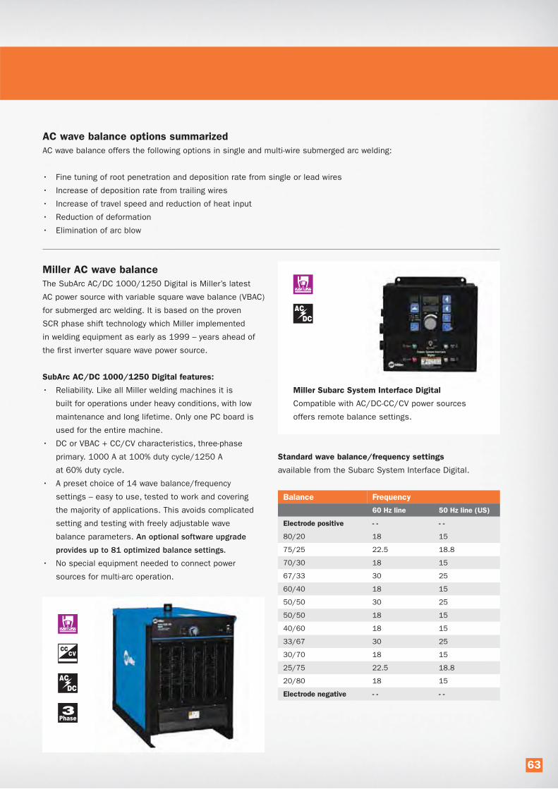
AC wave balance options summarized
AC wave balance offers the following options in single and multi-wire submerged arc welding:
• Fine tuning of root penetration and deposition rate from single or lead wires
• Increase of deposition rate from trailing wires
• Increase of travel speed and reduction of heat input
• Reduction of deformation
• Elimination of arc blow
Miller AC wave balance
The SubArc AC/DC 1000/1250 Digital is Miller’s latest
AC power source with variable square wave balance (VBAC)
for submerged arc welding. It is based on the proven
SCR phase shift technology which Miller implemented
in welding equipment as early as 1999 – years ahead of
the first inverter square wave power source.
SubArc AC/DC 1000/1250 Digital features:
• Reliability. Like all Miller welding machines it is
built for operations under heavy conditions, with low
maintenance and long lifetime. Only one PC board is
used for the entire machine.
• DC or VBAC + CC/CV characteristics, three-phase
primary. 1000 A at 100% duty cycle/1250 A
at 60% duty cycle.
• A preset choice of 14 wave balance/frequency
settings – easy to use, tested to work and covering
the majority of applications. This avoids complicated
setting and testing with freely adjustable wave
balance parameters. An optional software upgrade
provides up to 81 optimized balance settings.
• No special equipment needed to connect power
sources for multi-arc operation.
Miller Subarc System Interface Digital
Compatible with AC/DC-CC/CV power sources
offers remote balance settings.
Balance Frequency
60 Hz line 50 Hz line (US)
Electrode positive - - - -
80/20 18 15
75/25 22.5 18.8
70/30 18 15
67/33 30 25
60/40 18 15
50/50 30 25
50/50 18 15
40/60 18 15
33/67 30 25
30/70 18 15
25/75 22.5 18.8
20/80 18 15
Electrode negative - - - -
Standard wave balance/frequency settings
available from the Subarc System Interface Digital.
63

Strip cladding is used to create corrosion or wear resistant overlays on large non- or low-alloyed steel components used in,
for example, the chemical, petrochemical, nuclear, steel mills and paper and pulp industries. It provides a cost efficient
solution over using components in full stainless steel or Ni-alloys.
SAW strip cladding ESW strip cladding
Two process technologies
One technology is submerged arc strip cladding, formally
denominated SASC, but normally referred to as SAW strip
cladding. The other method is electroslag strip cladding.
The formal designation is ESSC, but is mostly called
ESW Strip cladding.
The SAW and ESW strip cladding processes use a strip
electrode to cover a wide area with each run.
Strip dimensions are typically 30, 60 or 90 x 0.5 mm,
but there is an increasing interest in 120 mm wide strip.
Specially developed welding fluxes are needed to obtain
the right characteristics for each process.
SAW strip cladding is an arc welding process. The function
of the flux is basically the same as in standard submerged
arc welding. It forms a slag to protect the weldpool and
supports the formation of the weld bead.
In ESW strip cladding there is no arc between the strip
and the parent metal and the flux is fed from only one
side. The molten slag is electrically conductive and the
heat needed to melt the strip and the parent metal sur-
face is generated by the electrical resistance in the weld
pool. Because of this, penetration and thus dilution is
lower than with SAW cladding. Due to the high temperature
of the weld pool and the high welding current a heavy duty
welding head is necessary. The high welding current may
cause weld defects such as uneven weld bead. This can
be prevented by using a magnetic steering device for larger
strip widths (≥ 60 mm / 2.4”). Moreover the ESW strip
cladding process burns off some elements from the strip
at a higher rate than SAW. The implication is that the strip
for ESW cladding has to have a slightly different chemistry
than SAW to achieve the desired chemistry of the deposit.
SAW and ESW strip cladding
64

ESW strip cladding has the following benefits
over SAW strip cladding:
• Increased deposition rate.
• High travel speed
• Low dilution
• Less penetration
• Comparable heat input
• Lower flux consumption.
• Weld deposit obtainable in one layer
Comparison between the SAW and ESW cladding methods:
Strip 60x0.5mm SAW ESW
Deposition rate 12-15 kg/h (26-33 lbs/h) 20-27 kg/h (44-59 lbs/h)
Travel speed 10-12 cm/min (4-5 inch/min) 18-24 cm/min (7-10 inch/min)
Arc voltage 26-28 V 24-26 V
Current 700-800 A 1200-1450 A
Dilution ~20% ~10%
Penetration >0.8 mm (>0.03”) <0.5 mm (<0.02”)
Heat input ~12 kJ/mm ~12 kJ/mm
No. of layers Min 2 Min 1
Deposit thickness ~8.5 mm (~1/3”) ~4.5 mm (3/16”)
Flux consumption 0.8 kg/kg strip (0.8 lbs/lbs strip) 0.6 kg/kg strip (0.6 lbs/lbs strip)
600 900 1200 1500 1800 2100 2400
Current (A)
Deposition rate SAW - ESW Strip cladding
SAW
ESW
For both SAW and ESW strip cladding, standard SAW
DC power sources are used. However, the current
capacity has to be more or less doubled for ESW strip
cladding, meaning that the investment cost for power
sources will be at least doubled compared to SAW strip
cladding. Furthermore ESW requires water cooling and
in many cases magnetic steering devices increasing
the difference in investment costs further. However,
when ESW strip cladding is technically feasible in the
application, the incremental investment costs for
ESW compared to SAW are typically easily off set by
the increased deposition rate and the fact that it is
possible to reach the desired weld metal chemistry
in one layer.
The current Hobart flux programme features one flux for
SAW strip cladding and two fluxes for ESW strip cladding.
SWX 305
SAW strip cladding with austenitic stainless steel strip
SWX 330
ESW strip cladding with austenitic stainless steel strip
SWX 382
ESW cladding with Ni-base strip
ITW Welding is a total solution provider; also for SAW and ESW strip cladding. An overview of our offerings for submerged
arc welding, submerged arc strip cladding and ESW strip cladding is presented in the back of this catalogue.
Deposit
ion r
ate
(lb
s/
h)
110
99
88
77
66
55
44
33
22
11
65

Porosity Probable cause Solution
Rusty plate Wire brush or grind
Oily plate Degrease or preheat
Wet plate Preheat
Wet flux Redry flux
Primer in welding zone Remove primer
Flux layer too thin Increase flux bed height
Contaminated joint Clean joint
Arc blow Reposition ground
Undercut Probable cause Solution
Voltage too high Adjust paparmeters
Travel speed too high Adjust travel speed
Tight slag Probable cause Solution
Voltage too high Adjust parameters
Incorrect wire size Adjust parameters
Irregular weld Adjust parameters
Welding zone too hot Cool down
Joint prep too narrow Adapt joint design
Burn through Probable cause Solution
Current too high Adjust parameters
Voltage too low Adjust parameters
Travel speed too low Adjust parameters
Root face to small Adjust parameters
Poor fit-up Improve fit-up
Longitudinal cracks Probable cause Solution
Concave bead profile Adjust parameters and torch position
Weld depth/width ratio > 1 Adjust parameters
Poor fit-up Improve fit-up
Rigid construction Preheat
Excessive length of weld pool Adjust parameters
Transverse cracks Probable cause Solution
Cooling rate too highPreheat, increase interpass
temperature, use preheated flux
Excessive restraint Preheat or adapt design
Moisture in fluxRedry flux
Trouble shooting
66
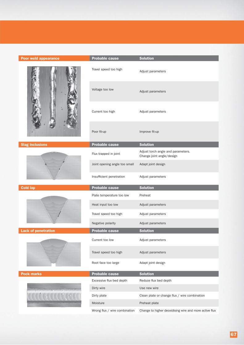
Poor weld appearance Probable cause Solution
Travel speed too highAdjust parameters
Voltage too lowAdjust parameters
Current too high Adjust parameters
Poor fit-up Improve fit-up
Slag inclusions Probable cause Solution
Flux trapped in jointAdjust torch angle and parameters.
Change joint angle/design
Joint opening angle too small Adapt joint design
Insufficient penetration Adjust parameters
Cold lap Probable cause Solution
Plate temperature too low Preheat
Heat input too low Adjust parameters
Travel speed too high Adjust parameters
Negative polarity Adjust parameters
Lack of penetration Probable cause Solution
Current too low Adjust parameters
Travel speed too high Adjust parameters
Root face too large Adapt joint design
Pock marks Probable cause Solution
Excessive flux bed depth Reduce flux bed depth
Dirty wire Use new wire
Dirty plate Clean plate or change flux / wire combination
Moisture Preheat plate
Wrong flux / wire combination Change to higher deoxidising wire and more active flux
67
Submerged Arc Welding
Equipment

Professional Technical Support for You
Process improvement - whether to increase output,
reduce rejects or meeting structural requirements -
are always profit boosting initiatives.
ITW Welding has assigned a dedicated expert
team aiming at improving submerged arc operations.
The team has access to a number of SubArc weld
centers where welding procedures are developed,
weld issues resolved and welding performances
improved. Our application experts share their time
between field support and development work and
are available for advanced consultations.
A unique offering
We can examine your submerged arc welding
processes and together review options for
improvements which will give real financial benefits.
Contact us and discover ways to optimize your
submerged arc processes to their full potential.
2www.MillerWelds.com3rd edition
Disclaimer: The information contained herein is furnished for reference purposes only and is believed to be accurate and reliable. Typical data are those obtained when welding and testing are performed in accordance with prescribed standards and guidelines. Other tests may produce differ-ent results and typical data should not be assumed to yield similar results in a particular application or weldment. ITW Welding does not assume responsibility for any results obtained by persons over whose methods it has no control. It is the user’s responsibility to determine the suitability of any products or methods mentioned herein for a particular purpose. In light of the foregoing, ITW Welding specifically disclaims all warranties, express or implied, including warranties of merchantability and fitness for a particular purpose, and further disclaims any liability for consequential or incidental damages of any kind, including lost profits.
Technology Increases SAW Deposition Rates . . . . . . . . . . . . . . . . . . . . . . . . . . . . . . . . . . . 4
Miller Submerged Arc System . . . . . . . . . . . . . . . . . . . . . . . . . . . . . . . . . . . . . . . . . . . . . . . 5
SubArc DC 650 / 800 Digital and Subarc 1000 / 1250 Digital . . . . . . . . . . . . . . . . . . . . . . . 5
SubArc AC/DC 1000 / 1250 Digital . . . . . . . . . . . . . . . . . . . . . . . . . . . . . . . . . . . . . . . . . . 5
SubArc System Interface Digital . . . . . . . . . . . . . . . . . . . . . . . . . . . . . . . . . . . . . . . . . . . . . . 5
SAW Accessories . . . . . . . . . . . . . . . . . . . . . . . . . . . . . . . . . . . . . . . . . . . . . . . . . . . . . . . . 6
Miller Tractor MT 1500 . . . . . . . . . . . . . . . . . . . . . . . . . . . . . . . . . . . . . . . . . . . . . . . . . . . . 6
Wire Drive Assemblies . . . . . . . . . . . . . . . . . . . . . . . . . . . . . . . . . . . . . . . . . . . . . . . . . . . . 6
SubArc Flux Hopper Digital Low Voltage . . . . . . . . . . . . . . . . . . . . . . . . . . . . . . . . . . . . . . . . 6
Compressed Air Flux Feeder . . . . . . . . . . . . . . . . . . . . . . . . . . . . . . . . . . . . . . . . . . . . . . . . 6
Submerged Arc Torches System . . . . . . . . . . . . . . . . . . . . . . . . . . . . . . . . . . . . . . . . . . . . . 7
OBT 600 . . . . . . . . . . . . . . . . . . . . . . . . . . . . . . . . . . . . . . . . . . . . . . . . . . . . . . . . . . . . . . 7
OBT 1200 . . . . . . . . . . . . . . . . . . . . . . . . . . . . . . . . . . . . . . . . . . . . . . . . . . . . . . . . . . . . . 7
Single Wire Torch Short / Long . . . . . . . . . . . . . . . . . . . . . . . . . . . . . . . . . . . . . . . . . . . . . . 7
Twin Arc Torch Short / Long . . . . . . . . . . . . . . . . . . . . . . . . . . . . . . . . . . . . . . . . . . . . . . . . . 7
Single Wire Narrow Gap Torch . . . . . . . . . . . . . . . . . . . . . . . . . . . . . . . . . . . . . . . . . . . . . . . 7
Tandem Wire Narrow Gap Torch . . . . . . . . . . . . . . . . . . . . . . . . . . . . . . . . . . . . . . . . . . . . . . 7
Single Wire Narrow Gap Flat Torch . . . . . . . . . . . . . . . . . . . . . . . . . . . . . . . . . . . . . . . . . . . . 7
Cladding Heads (external and internal) . . . . . . . . . . . . . . . . . . . . . . . . . . . . . . . . . . . . . . . . 8
60 mm Cladding Head . . . . . . . . . . . . . . . . . . . . . . . . . . . . . . . . . . . . . . . . . . . . . . . . . . . . 8
90 mm Cladding Head . . . . . . . . . . . . . . . . . . . . . . . . . . . . . . . . . . . . . . . . . . . . . . . . . . . . 8
120 mm Cladding Head . . . . . . . . . . . . . . . . . . . . . . . . . . . . . . . . . . . . . . . . . . . . . . . . . . . 8
8” Diameter Head . . . . . . . . . . . . . . . . . . . . . . . . . . . . . . . . . . . . . . . . . . . . . . . . . . . . . . . 8
10” Diameter Head. . . . . . . . . . . . . . . . . . . . . . . . . . . . . . . . . . . . . . . . . . . . . . . . . . . . . . . 8
12” Diameter Head. . . . . . . . . . . . . . . . . . . . . . . . . . . . . . . . . . . . . . . . . . . . . . . . . . . . . . . . 8
Accessories . . . . . . . . . . . . . . . . . . . . . . . . . . . . . . . . . . . . . . . . . . . . . . . . . . . . . . . . . . . . 9
Magnetic Steering Device . . . . . . . . . . . . . . . . . . . . . . . . . . . . . . . . . . . . . . . . . . . . . . . . . . 9
Strip De-Reeler . . . . . . . . . . . . . . . . . . . . . . . . . . . . . . . . . . . . . . . . . . . . . . . . . . . . . . . . . . 9
ProHeatTM Rolling Inductor . . . . . . . . . . . . . . . . . . . . . . . . . . . . . . . . . . . . . . . . . . . . . . . . . . 9
Table of Contents
3
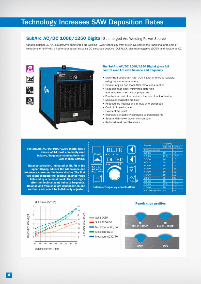
4
Ø 4.0 mm (5/32”)
Welding current (Amp.)
Deposi
tion r
ate
(kg
/h)
19
17
15
13
11
9
7
5
3500 550 600 650 700 750 800 850 900
Solid DCEP
Solid AC66/34
Metalcore AC66/34
Metalcore DCEP
Metalcore AC30/70
Penetration profiles
AC
66% EP / 34%EN
DCEP
AC
34% EP / 66%EN
DCEN
SubArc AC/DC 1000/1250 Digital Submerged Arc Welding Power Source
Variable balance AC/DC squarewave submerged arc welding (SAW) technology from Miller overcomes the traditional problems or
limitations of SAW with all other processes including DC electrode positive (DCEP), DC electrode negative (DCEN) and traditional AC.
The SubArc AC/DC 1000/1250 Digital gives full
control over AC wave balance and frequency
• Maximized deposition rate. 30% higher or more is feasible,
using the same parameters.
• Smaller angles and lower filler metal consumption
• Reduced heat input, minimized distortion
and increased mechanical properties
• Penetration control to minimize the risk of lack of fusion
• Minimized magnetic arc blow
• Reduced arc interactions in multi-wire processes
• Control of bead shape
• Excellent arc start
• Improved arc stability compared to traditional AC
• Substantially lower power consumption
• Reduced weld over thickness
Technology Increases SAW Deposition Rates
The SubArc AC/DC 1000/1250 Digital has a choice of 14 most commonly used
balance/frequency combinations and user-friendly setting.
Balance selection, indicated by BL.FR in the upper display, adjusts the AC balance and
frequency, shown on the lower display. The first two digits indicate the positive balance value
followed by a decimal point. The two digits after the decimal point indicate frequency.
Balance and frequency are dependent on one another, and cannot be individually adjusted.
BL.FR
DC.EPProgram
SETUPSEQUENCE
(sec)
t1
BalanceFrequency
60hz line 50hz line
Electrode positive – – – –
80/20 18 15
75/25 22.5 18.8
70/30 18 15
67/33 30 25
60/40 18 15
50/50 30 25
50/50 18 15
40/60 18 15
33/67 30 25
30/70 18 15
25/75 22.5 18.8
20/80 18 15
Electrode negative – – – –
Balance/frequency combinations
41.9
37.5
33
18.7
14.2
19.8
15.4
11
6.6
Deposi
tion r
ate
(lb
s/h)
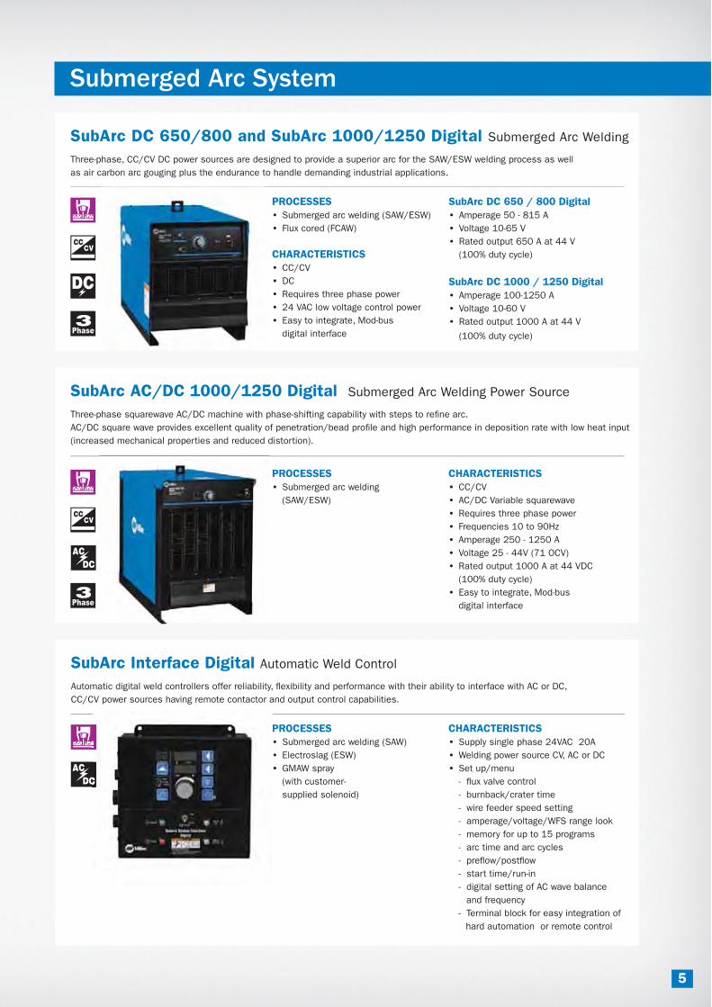
5
Submerged Arc System
SubArc DC 650/800 and SubArc 1000/1250 Digital Submerged Arc Welding
Three-phase, CC/CV DC power sources are designed to provide a superior arc for the SAW/ESW welding process as well
as air carbon arc gouging plus the endurance to handle demanding industrial applications.
PROCESSES
• Submerged arc welding (SAW/ESW)
• Flux cored (FCAW)
CHARACTERISTICS
• CC/CV
• DC
• Requires three phase power
• 24 VAC low voltage control power
• Easy to integrate, Mod-bus
digital interface
SubArc AC/DC 1000/1250 Digital Submerged Arc Welding Power Source
Three-phase squarewave AC/DC machine with phase-shifting capability with steps to refine arc.
AC/DC square wave provides excellent quality of penetration/bead profile and high performance in deposition rate with low heat input
(increased mechanical properties and reduced distortion).
PROCESSES
• Submerged arc welding
(SAW/ESW)
CHARACTERISTICS
• CC/CV
• AC/DC Variable squarewave
• Requires three phase power
• Frequencies 10 to 90Hz
• Amperage 250 - 1250 A
• Voltage 25 - 44V (71 OCV)
• Rated output 1000 A at 44 VDC
(100% duty cycle)
• Easy to integrate, Mod-bus
digital interface
SubArc Interface Digital Automatic Weld Control
Automatic digital weld controllers offer reliability, flexibility and performance with their ability to interface with AC or DC,
CC/CV power sources having remote contactor and output control capabilities.
PROCESSES
• Submerged arc welding (SAW)
• Electroslag (ESW)
• GMAW spray
(with customer-
supplied solenoid)
CHARACTERISTICS
• Supply single phase 24VAC 20A
• Welding power source CV, AC or DC
• Set up/menu
- flux valve control
- burnback/crater time
- wire feeder speed setting
- amperage/voltage/WFS range look
- memory for up to 15 programs
- arc time and arc cycles
- preflow/postflow
- start time/run-in
- digital setting of AC wave balance
and frequency
- Terminal block for easy integration of
hard automation or remote control
SubArc DC 650 / 800 Digital
• Amperage 50 - 815 A
• Voltage 10-65 V
• Rated output 650 A at 44 V
(100% duty cycle)
SubArc DC 1000 / 1250 Digital
• Amperage 100-1250 A
• Voltage 10-60 V
• Rated output 1000 A at 44 V
(100% duty cycle)

SAW Accessories
Miller Tractor MT 1500
A motorized, highly flexible welding tractor designed
to produce, high quality submerged arc welds.
PROCESSES
• Submerged arc (SAW)
• Recommended
Miller power supplies
- SubArc DC 800 Digital
- SubArc DC 1250 Digital
- SubArc AC/DC 1250 Digital
PACKAGE INCLUDES
• Tractor
• Digital sysem interface
• RAD-400 drive motor
• Subarc Flux hopper Digital Low Voltage
• Wire reel
• Torch
• Remote start/stop control
• Tractor guide rolls
• Wire straightener
Wire Drive Assemblies
Miller offers either standard or high-speed 24 V Heavy-duty wire assemblies.
CHARACTERISTICS
• SubArc Strip Drive 100 Digital Low Voltage (ESW)
- Low speed, right-angle wire drive assembly
• SubArc Wire Drive 400 Digital Low Voltage
- Standard speed, right-angle wire drive assembly
• SubArc Wire Drive 780 Digital Low Voltage
- High speed, right-angle wire drive assembly
SubArc Flux Hopper Digital Low Voltage
Automatic flux valve will carry 11.3 kg (25 lbs) of flux. The opening is sized to allow hook-up
of any flux-hopper mounted recovery system. A slag screen is also provided.
DESCRIPTION
• 11.3 kg (25 lbs) capacity
• Power supply 24 V
Compressed Air Flux Feeder
The automatic air compressed flux feeding system is electronically controlled
to enable pre-heated flux to be kept at a constant temperature.
CHARACTERISTICS
• Storage capacity from 120 - 205 l (32 - 205 gal).
• Working temperature 100ºC (212ºF)
• Voltage supply 220 V
• Max input power 2800 W
• Max air pressure 6 bar (87 psi)
6

Submerged Arc Torches System
OBT 600
600 Amp,
100% duty
cycle torch
with concentric
flux flow nozzle.
PROCESS
• Submerged arc
welding (SAW)
• Wire diameter
1.6 - 5.5 mm
(1/16 - 7/32”)
OBT 1200
1200 Amp,
100% duty
cycle torch
with concentric
flux flow nozzle.
PROCESS
• Submerged Arc
Welding (SAW)
• Wire diameter
1.6 - 5.5 mm
(1/16 - 1/4”)
Single Wire Narrow Gap Torch
1200 Amp, 100% duty cycle
torch for narrow cap
PROCESS
• Submerged arc
welding (SAW)
• Wire diameter 2.4 - 4.0 mm
(3/32 - 5/32”)
• For depth 50 - 350 mm (2-14”)
• PTFE insulation
up to 200° C (390ºF)
• Insulation type Ceramic
up to 350° C (660ºF)
Single Wire Torch Short / Long
1200 Amp, 100% duty
cycle torches
PROCESS
• Submerged arc welding (SAW)
• Wire diameter 1.6 - 5.5 mm
(1/16 - 7/32”)
Short model: single wire welding nozzle
with an effective length of 220mm (5.6”).
Long model: single wire welding nozzle with
an effective length of 360 mm (14.2”).
W)
m
ding nozzle
0mm (5.6”).
ng nozzle with
Twin Arc Torch Short / Long
1200 Amp, 100% duty cycle twin torches
with concentric flux flow nozzle
PROCESS
• Submerged arc welding (SAW twin)
• Wire diameter 1.2 - 2.4 mm x 2
(0.47 - 3/32”)
Short model: twin arc welding torches
with an effective length of 220 mm (8.7”).
Long model: twin arc welding torches
with an effective length of 360 mm (14.2”).
Tandem Wire Narrow Gap Torch
800 Amp, 100% duty cycle
torches for narrow gap
PROCESS
• Submerged arc
welding (SAW)
• Wire diameter 2.4 - 4.0 mm
(3/32 - 5/32”)
• For depth 50 - 350 mm (2-14”)
• PTFE insulation
up to 200° C (390ºF)
• Ceramic insulation
up to 350° C (660ºF)
Single Wire Narrow Gap Flat Torch
800 Amp, 100% duty cycle
torch for narrow gap
PROCESS
• Submerged arc
welding (SAW)
• Wire diameter 2.4 - 4.0 mm
(3/32 - 5/23”)
• For depth 100 - 250 mm
(4 - 10”)
• Ceramic insulation
up to 350° C (660ºF)
7

Cladding Heads
120 mm Cladding Head
CHARACTERISTICS
• Max current 3600 A
(100% duty cycle)
• Dimension
230 x 230 x 470 mm
(8 x 9 x 19”)
• Weight 25 kg (55 lbs)
• Water cooled
• Strip width
60 - 90 - 120 mm
(2 3/8” - 3 1/2” - 4 3/4”)
8
12” Diameter Head
CHARACTERISTICS
• Minimum inside diameter
pipe clad 310 mm - 12”
• Max current 1000 A
(100% duty cycle)
• Dimension
1349 x 240 x 225 mm
(58 1/8 x 9 1/2 x 9”)
• Weight 27.5 kg
(61 lbs)
• Water cooled
• Strip width 30 mm
(1-3/16”)
90 mm Cladding Head
CHARACTERISTICS
• Max current 3000 A
(100% duty cycle)
• Dimension
220 x 230 x 400 mm
(8 x 9 x 16”)
• Weight 19 kg (41.8 lbs)
Water cooled
Strip width 30 – 60 - 90 mm
(1 3/16” - 2 3/8” - 3 1/2”)
10” Diameter Head
CHARACTERISTICS
• Minimum inside diameter
pipe clad 260 mm - 10”
• Max current 850 A
(100% duty cycle)
• Dimension
1349 x 200 x 200 mm
(58 1/8 x 8 x 8”)
• Weight 27 kg
(60 lbs)
• Water cooled
• Strip width 30 mm
(1-3/16”)
60 mm Cladding Head
CHARACTERISTICS
• Max current 2000 A
(100% duty cycle)
• Dimension
200 x 230 x 360 mm
(8 x 9 x 14’’)
Weight 13.5 kg (29.7 lbs)
• Water cooled
• Strip width 30 – 60 mm
(1 3/16” - 2 3/8”)
8” Diameter Head
CHARACTERISTICS
• Minimum inside diameter
pipe clad 203 mm - 8”
• Max current 750 A (100% duty cycle)
• Dimension 1349 x 150 x 150 mm
(58 1/8 x 6 x 6”)
• Weight 26.5 kg (59 lbs)
• Water cooled
• Strip width 30 mm (1-3/16”)
For Standard ApplicationIt is recommended that all cladding SAW/ESW heads are
used in conjunction with the Miller RAD 100/400 drive motor.
For Nozzle and Pipe ApplicationThe following head is designed for SAW/ESW
both circumferential and longitudinal cladding.

Accessories
Magnetic Steering Device
The magnetic steering device is intended for use with the ESW process. When used with stainless steel and nickel-base strip
and fluxes, it ensures that the cladding process achieves uniformity, in terms of level and uniform weld bead edge formation.
Additionally it controls the weld bead ripple formation which maintains the consistency of both bond integrity and appearance.
CHARACTERISTICS
• Weight 15 kg (33 lbs)
• Dimension 530 x 280 x 400 mm
(21 x 11 x 16”)
• Power 220V /110V 50 - 60 Hz
• Solenoid 10 A 24 VDC (red) / strip 90-120 mm (3.5 - 4.7”)
Strip De-Reeler
Strip spool holder from 150 to 1.000 Kg (330 - 2200 lbs.) with adjustable inner diameter.
ProHeat™ Rolling Inductor Induction Heating System
The ProHeat 35 Induction Heating System with the Rolling Inductor is a simple and cost-effective heating process that can
solve many preheating problems and deliver fast, consistent heat for pipe fabrication shops that weld pipe spools for the
refinery, petrochemical, power and HVAC industries.
BENEFITS
• Maximum productivity
- Quick time to temperature
- Heating while rolling allows
continuous fabrication
- No coiling of cable
- Compact and portable for use
throughout the pipeshop
• Improved safety
- Eliminates open flames
- Cooler shop environment and
reduced operator fatigue
• Optimal consistency and quality
- Even distribution of heat
eliminates quality issues ProHeat 35 Liquid-Cooled System with Rolling Inductor. (Pipe stands sold separately.)
Rated OutputAmbient Temperature Range
Storage Usage
Maximum Part
Preheat TemperatureRequired Cooler Dimensions
Shipping
Weight
350 Amps at
100% Duty Cycle
-40° C to 82°C
(-40° F to 180° F)
0° C to 60°C
(32° F to 140° F)
315° C (600° F) * Miller Heavy-Duty Induction
Cooler (#195 406) with
coolant (#300 355)
H: (133 mm) 5.25 in.
W: (168 mm) 6.6 in.
D: (203 mm) 8 in.
18.1 kg
(40 lb)
Specially designed forpreheating rolled pipe
9
APPLICATIONS
• Process piping
• Refinery
• Petrochemical
• Power piping
• Pressure vessels