Subject Code: 17511 Model Answer Page 1 of 33 Important...
33
MAHARASHTRA STATE BOARAD OF TECHNICAL EDUCATIOD (Autonomous) (ISO/IEC-27001-2005 Certified) WINTER– 2014 Examinations Subject Code: 17511 Model Answer Page 1 of 33 Important suggestions to examiners: 1) The answers should be examined by key words and not as word-to-word as given in the model answer scheme. 2) The model answer and the answer written by candidate may vary but the examiner may try to assess the understanding level of the candidate. 3) The language errors such as grammatical, spelling errors should not be given more importance. (Not applicable for subject English and communication skills) 4) While assessing figures, examiner may give credit for principle components indicated in a figure. The figures drawn by candidate and model answer may vary. The examiner may give credit for any equivalent figure drawn. 5) Credits may be given step wise for numerical problems. In some cases, the assumed constant values may vary and there may be some difference in the candidate’s answers and model answer. 6) In case some questions credit may be given by judgment on part of examiner of relevant answer based on candidate understands. 7) For programming language papers, credit may be given to any other program based on equivalent concept. Q.1 A) Attempt any three of the following: 12 Marks i) State why three phase induction motor never run on synchronous speed? Ans: (4 Marks) The working principle of three phase induction motor is based on relative motion between rotating magnetic field and rotor conductors i.e (N S - N), According to Lenz’s law rotor will try to catch the synchronous speed of rotating magnetic field to oppose the ‘cause producing it’. But rotor never succeeds due to frictional losses. If rotor catches the synchronous speed of rotating magnetic field, (N S - N) i.e relative motion will be zero and rotor stops to rotate and therefore three phase induction motor can never run on synchronous speed . OR Relative motion between rotor conductors and rotating magnetic field induces rotor currents. Interaction of rotor current of stator flux produces torque on rotor which means that relative motion of rotor is the cause of rotation of rotor. In No-load condition, due to friction of Windage rotor has to produce a small torque to overcome frictional force and thus rotor speed never catches synchronous speed .
Transcript of Subject Code: 17511 Model Answer Page 1 of 33 Important...

MAHARASHTRA STATE BOARAD OF TECHNICAL EDUCATIOD (Autonomous)
(ISO/IEC-27001-2005 Certified)
WINTER– 2014 Examinations
Subject Code: 17511 Model Answer Page 1 of 33
Important suggestions to examiners:
1) The answers should be examined by key words and not as word-to-word as given in the model answer scheme.
2) The model answer and the answer written by candidate may vary but the examiner may try to assess the understanding level of the candidate.
3) The language errors such as grammatical, spelling errors should not be given more importance. (Not applicable for subject English and communication skills)
4) While assessing figures, examiner may give credit for principle components indicated in a figure. The figures drawn by candidate and model answer may vary. The examiner may give credit for any equivalent figure drawn.
5) Credits may be given step wise for numerical problems. In some cases, the assumed constant values may vary and there may be some difference in the candidate’s answers and model answer.
6) In case some questions credit may be given by judgment on part of examiner of relevant answer based on candidate understands.
7) For programming language papers, credit may be given to any other program based on equivalent concept.
Q.1 A) Attempt any three of the following: 12 Marks i) State why three phase induction motor never run on synchronous speed?
Ans: (4 Marks)
The working principle of three phase induction motor is based on relative
motion between rotating magnetic field and rotor conductors i.e (NS - N), According
to Lenz’s law rotor will try to catch the synchronous speed of rotating magnetic field
to oppose the ‘cause producing it’. But rotor never succeeds due to frictional losses.
If rotor catches the synchronous speed of rotating magnetic field, (NS - N) i.e
relative motion will be zero and rotor stops to rotate and therefore three phase
induction motor can never run on synchronous speed .
OR
Relative motion between rotor conductors and rotating magnetic field induces
rotor currents. Interaction of rotor current of stator flux produces torque on rotor
which means that relative motion of rotor is the cause of rotation of rotor. In No-load
condition, due to friction of Windage rotor has to produce a small torque to overcome
frictional force and thus rotor speed never catches synchronous speed .

MAHARASHTRA STATE BOARAD OF TECHNICAL EDUCATIOD (Autonomous)
(ISO/IEC-27001-2005 Certified)
WINTER– 2014 Examinations
Subject Code: 17511 Model Answer Page 2 of 33
ii) State the effect of rotor resistance on torque of an induction motor. Ans: Characteristics: (2 Mark Characteristics & 2 Mark Effect)
Equivalent Characteristics
Effect: When rotor resistance increases, maximum torque condition occurs at higher
values of slip and characteristics shifts towards left hand side.
The maximum torque condition can be obtained at any required slip by changing
rotor resistance.
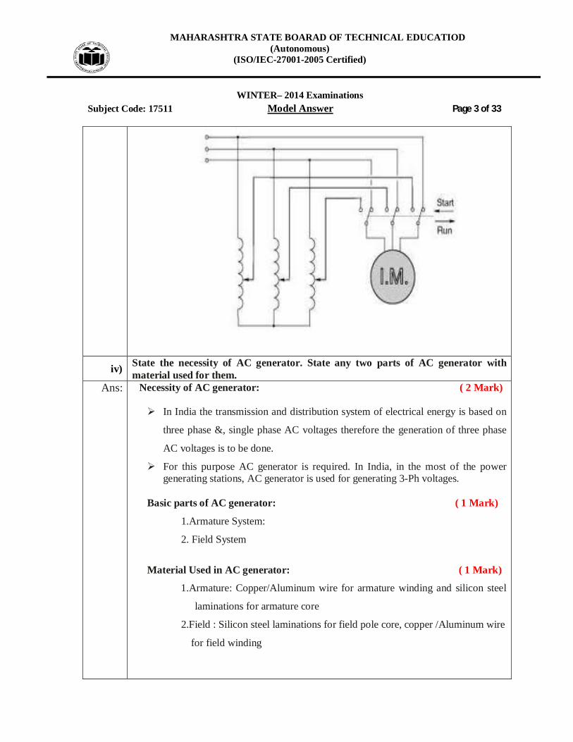
iii) Draw a neat diagram for Autotransformer starter used in 3 phase induction motor. Ans: Diagram for Autotransformer starter : ( 4 Marks)
OR
MAHARASHTRA STATE BOARAD OF TECHNICAL EDUCATIOD (Autonomous)
(ISO/IEC-27001-2005 Certified)
WINTER– 2014 Examinations
Subject Code: 17511 Model Answer Page 3 of 33
iv) State the necessity of AC generator. State any two parts of AC generator with material used for them.
Ans: Necessity of AC generator: ( 2 Mark) In India the transmission and distribution system of electrical energy is based on
three phase &, single phase AC voltages therefore the generation of three phase
AC voltages is to be done.
For this purpose AC generator is required. In India, in the most of the power generating stations, AC generator is used for generating 3-Ph voltages.
Basic parts of AC generator: ( 1 Mark)
1.Armature System:
2. Field System
Material Used in AC generator: ( 1 Mark)
1.Armature: Copper/Aluminum wire for armature winding and silicon steel
laminations for armature core
2.Field : Silicon steel laminations for field pole core, copper /Aluminum wire
for field winding

MAHARASHTRA STATE BOARAD OF TECHNICAL EDUCATIOD (Autonomous)
(ISO/IEC-27001-2005 Certified)
WINTER– 2014 Examinations
Subject Code: 17511 Model Answer Page 4 of 33
Q.1B) Attempt any one of the following : 06 Marks i) Explain voltage frequency method of speed control of 3 phase induction motor.
Ans: Figure: (3 Mark Figure & 3 Mark Effect)
OR Equivalent fig Explanation: A simple circuit arrangement for obtaining variable voltage and frequency is as
shown in the above figure. This type of control is usually known as Volts/ Hertz or V/f control. If the ratio of voltage to frequency is kept constant, the flux remains constant. The maximum torque which is independent of frequency can be maintained
approximately constant. However at a low frequency, the air gap flux is reduced due to drop in the stator
impedance and the voltage has to be increased to maintain the torque level.
ii) Draw a schematic diagram of an a.c. series motor. How to change its speed and direction of rotation? Give two applications of a.c. series motors.
Ans: Schematic diagram of an A.C Series motor: (2 Mark)
OR

MAHARASHTRA STATE BOARAD OF TECHNICAL EDUCATIOD (Autonomous)
(ISO/IEC-27001-2005 Certified)
WINTER– 2014 Examinations
Subject Code: 17511 Model Answer Page 5 of 33
Reason for change its speed: (1 Mark) Since the speed of this motor is not imitated by the supply frequency hence the
speed control of this motor is best obtained by solid state devices. Reason for change its direction of rotation: (1 Mark) The direction of rotation can be changed by interchanging connection to the
field with respect to the armature. Applications of A.C Series Motor (Any two from following or any similar ) (2 Mark)
1. Where high starting torque is required e.g. Electric Traction 2. Stone Crushing Machine
3. Washing Machines. 4. Mixers and grinders 5. Food processors. 6. Small drilling Machines. 7. In main line service 8. In Electric Traction
Q.2 Attempt any four of the following : 16 Marks
a) Explain with neat sketches, the production of rotating magnetic field in three phase induction motor
Ans: Figure: Waveform of 3-ph fluxes:
or Equivalent fig.----- (1 Mark) Vector diagram at i) wt = 0 ii) wt = 600 iii) wt = 1200
or Equivalent fig. ------------ (2 Marks)

MAHARASHTRA STATE BOARAD OF TECHNICAL EDUCATIOD (Autonomous)
(ISO/IEC-27001-2005 Certified)
WINTER– 2014 Examinations
Subject Code: 17511 Model Answer Page 6 of 33
i) Wt = 00, mr 23
ii) Wt =600, mr 23
iii) Wt =1200, mr 23
From the above vector diagrams at different phase angles particularly at 00, 600 and 1200 referred in waveform diagram, it is clear that the resultant flux vector is not stationary but it rotates with NS ------------------------------------ (1 Mark)
b)
A 3(1), 50 Hz, 4 pole, I.M. has a slip of 4% Calculate: 1) Speed of motor 2) Frequency of rotor emf if the rotor has a resistance of 1Ω and standstill reactance of 4Ω. Calculate the rotor power factor at i) standstill ii)a speed of 1440 rpm
Ans: Given Data: 3 ph,4-pole, 50Hz
450120P
f120NS
…………….…………………………………..…..(1/2 Mark)
RPM1500
450120NS
0.04 1500)S1(N
1500)04.01(N
RPM1440N …………….………………………………..( 1/2 Mark)
Frequency of Rotor = S . f…………….…………………….……..( 1/2 Mark) = 0.04 X 50 Frequency of Rotor = 2.0 Hz ………………………..…… ( 1/2 Mark) i) Power factor at stand still i.e s=1
22
222
22
X)S()R(
RCos
…………….………………………...……..( 1/2 Mark)
222
)4()1(1Cos
lag2425.0Cos 2 ……………………...…… ( 1/2 Mark) ii) Power factor at speed of 1440 RPM i.e at s= 0.04 :
222
2
22
X)S()R(
RCos
………………………….….…..( 1/2 Mark)
2222
)4()04.0()1(1Cos
lag9874.0Cos 2 ……………………...…… ( 1/2 Mark)
MAHARASHTRA STATE BOARAD OF TECHNICAL EDUCATIOD (Autonomous)
(ISO/IEC-27001-2005 Certified)
WINTER– 2014 Examinations
Subject Code: 17511 Model Answer Page 7 of 33
c) Explain the factors which affect the terminal voltage of alternator. Ans: The factors affecting terminal voltage of alternator: (1 Mark each point)
The terminal voltage of alternator depends upon: (Any four point are expected)
1) Load current
2) Armature resistance per phase
3) Leakage reactance per phase
4) Armature reaction reactance per phase
5) Excitation (field current)
6) Speed
7) Load power factor OR when load power factor is unity or lagging, the terminal
voltage drops with increase in load, when the load power factor is leading, the
terminal voltage increase with increase in load
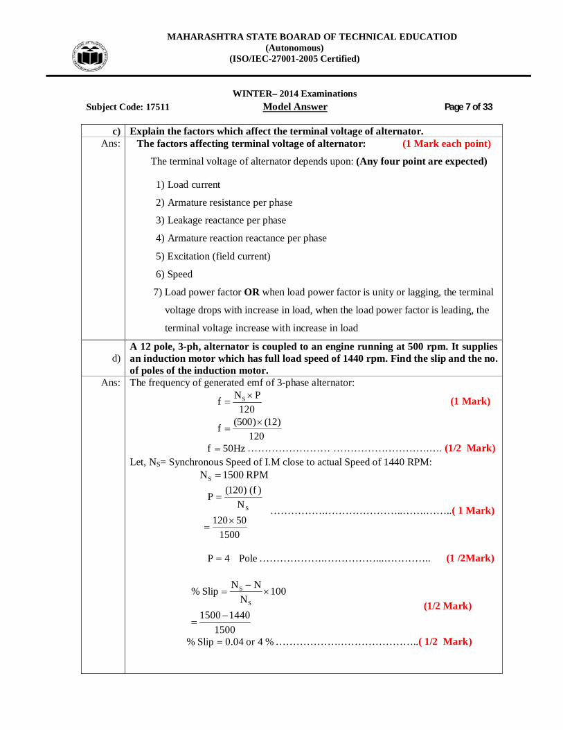
d) A 12 pole, 3-ph, alternator is coupled to an engine running at 500 rpm. It supplies an induction motor which has full load speed of 1440 rpm. Find the slip and the no. of poles of the induction motor.
Ans: The frequency of generated emf of 3-phase alternator:
120
PNf S
(1 Mark)
120
)12()500(f
Hz50f …………………… ……………………….…. (1/2 Mark) Let, NS= Synchronous Speed of I.M close to actual Speed of 1440 RPM: RPM1500NS
150050120N
)f()120(PS
…………….…………………..…….……..( 1 Mark)
Pole4P ……………….……………...………….. (1 /2Mark)
150014401500
100N
NNSlip%S
S
(1/2 Mark)
%4or04.0Slip% ……………….…………………..( 1/2 Mark)
MAHARASHTRA STATE BOARAD OF TECHNICAL EDUCATIOD (Autonomous)
(ISO/IEC-27001-2005 Certified)
WINTER– 2014 Examinations
Subject Code: 17511 Model Answer Page 8 of 33
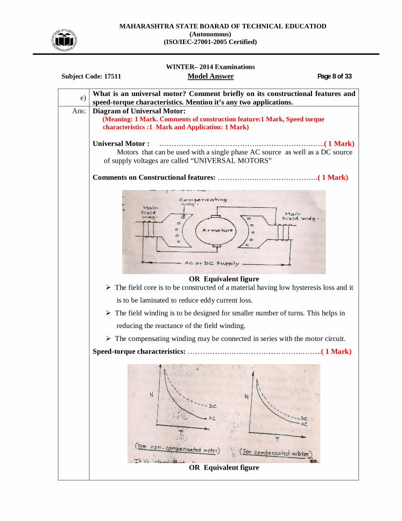
e) What is an universal motor? Comment briefly on its constructional features and speed-torque characteristics. Mention it’s any two applications.
Ans: Diagram of Universal Motor: (Meaning: 1 Mark. Comments of construction feature:1 Mark, Speed torque characteristics :1 Mark and Application: 1 Mark)
Universal Motor : …………….…………………….………………….…..( 1 Mark)
Motors that can be used with a single phase AC source as well as a DC source of supply voltages are called “UNIVERSAL MOTORS”
Comments on Constructional features: …………….…………………….( 1 Mark)
OR Equivalent figure
The field core is to be constructed of a material having low hysteresis loss and it
is to be laminated to reduce eddy current loss.
The field winding is to be designed for smaller number of turns. This helps in
reducing the reactance of the field winding.
The compensating winding may be connected in series with the motor circuit.
Speed-torque characteristics: …………….………………………….……..( 1 Mark)
OR Equivalent figure

MAHARASHTRA STATE BOARAD OF TECHNICAL EDUCATIOD (Autonomous)
(ISO/IEC-27001-2005 Certified)
WINTER– 2014 Examinations
Subject Code: 17511 Model Answer Page 9 of 33
Comments: As torque increases speed decreases, the characteristics is similar with DC
series motor. Application of Universal Motor: ( Any Two application expected) .( 1 Mark)
1) Mixer
2) Food processor
3) Heavy duty machine tools
4) Grinder
5) Vacuum cleaners
6) Refrigerators
7) Driving sewing machines
8) Electric Shavers
9) Hair dryers
10) Small Fans
11) Cloth washing machine
12) portable tools like blowers, drilling machine, polishers etc
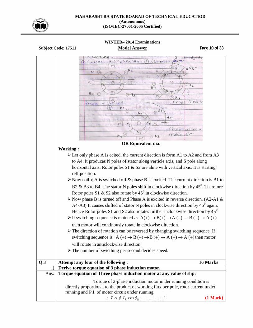
f) Explain the working principle of permanent magnet stepper motor Ans: Permanent Magnet Stepper Motor:- ( Figure 2 Mark & Working 2 Mark)
or Working :- If the phase is excited in ABCD, due to electromagnetic torque is developed by interaction between the magnetic field set up by exciting winding and permanent magnet. Rotor will be driven in clockwise direction. OR Working principle: unlike poles attract each other.
OR
MAHARASHTRA STATE BOARAD OF TECHNICAL EDUCATIOD (Autonomous)
(ISO/IEC-27001-2005 Certified)
WINTER– 2014 Examinations
Subject Code: 17511 Model Answer Page 10 of 33
OR Equivalent dia.
Working : Let only phase A is ecited, the current direction is form A1 to A2 and from A3
to A4. It produces N poles of stator along verticle axis, and S pole along horizontal axis. Rotor poles S1 & S2 are aline with vertical axis. It is starting reff.position.
Now coil A is switched off & phase B is excited. The current direction is B1 to B2 & B3 to B4. The stator N poles shift in clockwise direction by 450. Therefore Rotor poles S1 & S2 also rotate by 450 in clockwise direction.
Now phase B is turned off and Phase A is excited in reverse direction. (A2-A1 & A4-A3) It causes shifted of stator N poles in clockwise direction by 450 again. Hence Rotor poles S1 and S2 also rotates further inclockwise direction by 450
If switching sequence is mainted as )(A)(B)(A)(B)(A then motor will continously rotate in clockwise direction.
The direction of rotation can be reversed by changing switching sequence. If switching sequence is )(A)(A)(B)(B)(A then motor will rotate in anticlockwise direction.
The number of swicthing per second decides speed.
Q.3 Attempt any four of the following : 16 Marks a) Derive torque equation of 3 phase induction motor.
Ans: Torque equation of Three phase induction motor at any value of slip:
Torque of 3-phase induction motor under running condition is directly proportional to the product of working flux per pole, rotor current under running and P.f. of motor circuit under running.
1.....................cos RRIT (1 Mark)
MAHARASHTRA STATE BOARAD OF TECHNICAL EDUCATIOD (Autonomous)
(ISO/IEC-27001-2005 Certified)
WINTER– 2014 Examinations
Subject Code: 17511 Model Answer Page 11 of 33
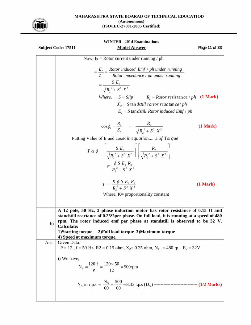
Now, IR = Rotor current under running / ph
runningunderphimpedanceRotorrunningunderphEmfinducedRotor
ZE
r
r
//
phEmfinducedRotordstillSEphcereacrortordstillSX
phceresisRotorRSlipSWhereXSR
ES
/tan/tantan
/tan,
2
2
2
2222
2
(1 Mark)
r
r ZR2cos
2222
2
XSRR
(1 Mark)
Putting Value of Ir and cos Torqueofequationinr 1.......
T
2222
2
2222
2
XSR
R
XSR
ES
222
2
22
XSRRES
222
2
22
XSRRESKT
(1 Mark)
Where, K= proportionality constant
b)
A 12 pole, 50 Hz, 3 phase induction motor has rotor resistance of 0.15 Ω and standstill reactance of 0.25Ωper phase. On full load, it is running at a speed of 480 rpm. The rotor induced emf per phase at standstill is observed to be 32 V. Calculate: 1)Starting torque 2)Full load torque 3)Maximum torque 4) Speed at maximum torque.
Ans: Given Data: P = 12 , f = 50 Hz, R2 = 0.15 ohm, X2= 0.25 ohm, NFL = 480 rp,, E2 = 32V i) We have,
rpm50012
50120P
f120NS
)D(s.p.r33.860
50060N
.s.p.rinN SS
S ------------------------------- (1/2 Marks)

MAHARASHTRA STATE BOARAD OF TECHNICAL EDUCATIOD (Autonomous)
(ISO/IEC-27001-2005 Certified)
WINTER– 2014 Examinations
Subject Code: 17511 Model Answer Page 12 of 33
ii) Staring Torque: We have
22
22
2
XRR.CStartingT
…………….…………………….……..( 1/2 Mark)
Where,
22
S
EN2
3C
22
2
st )25.0()15.0(15.0)32(
33.823T
MN53.103Tst iii) Full load Torque at full load:
04.0
500480500
NNNSS
…………….………………………..……..( 1 /2Mark)
22FL
222
2FLFL XSR
R.S.CT
22
2
FL )25.004.0()15.0(15.0)32()04.0(
33.823T
MN58.15TFL ----------------------- (II) ----------------...-------(1 /2Marks) iv) Maximum Torque:
2X2
CmaxT
…………….…………………………….……..( 1 /2Mark)
2
22
S X2E
D23C
)25.0(2
)32(33.82
3maxT2
MN38.117maxT ---------------------- (III) --------------------- (1/2 Marks)

MAHARASHTRA STATE BOARAD OF TECHNICAL EDUCATIOD (Autonomous)
(ISO/IEC-27001-2005 Certified)
WINTER– 2014 Examinations
Subject Code: 17511 Model Answer Page 13 of 33
v) The maximum torque occurs at a Slip:
6.0
25.015.0Smate.i
XRSm
2
2
…………….…………………….……..( 1/2 Mark)
:torqueMaximumatSpeed SN)Sm1(N m ----------------------- (IV) ------------------(1/2 Marks) 500)6.01(N N = 200 rpm.
c) A 16 pole, 3 phase star connected alternator armature has 12 slots with 24 conductors per slot and the flux per pole is 0.1 Wb. sinusoidally distributed. Calculate the line emf generated at 50 Hz.
Ans: 3Ph, Star connected, 16 pole, 50 Hz, alternator KdKcTf44.4ph/E ----------------------------------------------------(1/2 Marks) m= Number of slots/Pole/phase
m= 25.0316
12
75.0
1612
PoleSlotsof.NopitchpoleWhere
pitchPole.Elec1800
-------------------------(1/2 Marks)
75.0
.Elec1800
Elect2400 Considering Full pitched winding 1KC
)2/(Sinm)2/m(SinKd
------------------------------------------------------ (1/2 Marks)
)]2/240(Sin[25.0)]2/240()25.0[(SinKd
2165.0Kd givenWb1.0

MAHARASHTRA STATE BOARAD OF TECHNICAL EDUCATIOD (Autonomous)
(ISO/IEC-27001-2005 Certified)
WINTER– 2014 Examinations
Subject Code: 17511 Model Answer Page 14 of 33
3
seriesinconductorsofnumberTotalphZ --------------------------(1/2 Marks)
3
1224phZ
96phZ
2
962ph/ZphT:phaseperseriesinturnsofNumber
48phT KdKcTf44.4ph/E ------------------------------------------- (1/2 Marks) )2165.0()1()48()50()1.0(44.4ph/E volts7.230ph/E ---------------------------------------------------- (1/2 Marks) E line = Eph3 ---------------------------------------------------------- (1/2 Marks) volts59.399lineE ------------------------------------------------------ (1 /2Marks)
d) Derive the emf equation of alternator. Ans: EMF Equation of alternator:
Let, P = no. of rotor poles. = Flux per pole Z= Number of stator conductors
N = Speed in rpm
turns per phase (Tph) 2PhZ
Frequency of induced emf is
f = Cycles per rotation x rotation per sec
602NP
120PNf ---------------------------------------------- (1/2 Marks)
Consider one rotation of rotor then change in flux linkage is,
d P. Time required for one rotation is,
.60)60(
11 SecNNn
dt -------------- (1 Marks)
By faradays law of Electromagnetic induction

MAHARASHTRA STATE BOARAD OF TECHNICAL EDUCATIOD (Autonomous)
(ISO/IEC-27001-2005 Certified)
WINTER– 2014 Examinations
Subject Code: 17511 Model Answer Page 15 of 33
Average emf per conductor = dtd
ave / Conductor = )60(
.NP
ave / Conductor = Volt60
NP
------(1/2 Marks)
ave / turn = 2 ave/ Conductor VoltNP
60
ave / turn = 2 VoltNP
60
= VoltNP
1204
= )120
(4 NP
ave / turn = )120
(4 NPff
ave / Phs = ave / x Number of turns per phase
= PhTf 4 -------------------------------------- (1/2 Marks)
RMS Value per phase is given by,
Eph = Eph (ave) x Form Factor
= 11.14 PhTf ------------------------- (1 Marks)
Eph = voltsTf.44.4 Ph
It is for full pitched concentrated winding. If winding is distributed & short pitched then
EPh = voltskc.kd.T.f.44.4 Ph
-------------- (1/2 Marks)
Where, Kc = coil span factor or chording factor
Kd = Distribution factor

MAHARASHTRA STATE BOARAD OF TECHNICAL EDUCATIOD (Autonomous)
(ISO/IEC-27001-2005 Certified)
WINTER– 2014 Examinations
Subject Code: 17511 Model Answer Page 16 of 33
e) Why a single phase induction motor doesn't have a self starting torque? Explain the double revolving field theory.
Ans: Reason for single phase induction motor doesn't have a self starting torque: (2 Mark) Tf = K.I2
2. R2/S TB = - K I2
2 R2 / (2-S) At Start S = 1 Tf = -Tb hence starting torque = 0 hence motor doesn't have a self starting
torque OR
When single phase AC supply is given to main winding it produces alternating flux.
According to double field revolving theory, alternating flux can be represented by two opposite rotating flux of half magnitude.
These oppositely rotating flux induce current in rotor & there interaction produces two opposite torque hence the net torque is Zero and the rotor remains standstill.
Hence Single-phase induction motor is not self starting. OR When single phase A.C supply is applied across the single phase stator winding, an alternating field is produced. The axis of this field is stationary in horizontal direction. The alternating field will induce an emf in the rotor conductors by transformer action. Since the rotor has closed circuit, current will flow through the rotor conductors. Due to induced emf and current in the rotor conductors the force experienced by the upper conductors of the rotor will be downward and the force experienced by the lower conductors of the rotor will be upward .The two sets of force will cancel each other and the rotor will experience no torque .Therefore single phase motors are not self starting.
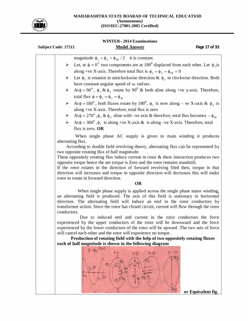
Double field revolving theory: ---------------------------------------------- (2Mark)
Consider two components of flux namely 21 & each having equal
MAHARASHTRA STATE BOARAD OF TECHNICAL EDUCATIOD (Autonomous)
(ISO/IEC-27001-2005 Certified)
WINTER– 2014 Examinations
Subject Code: 17511 Model Answer Page 17 of 33
magnitude 2/M21 it is constant. Let, at 00 two components are at 1800 displaced from each other. Let 1 is
along +ve X-axis. Therefore total flux is 0M21 Let 1 is rotation in anticlockwise direction & 2 in clockwise direction. Both
have constant angular speed of rad/sec. At 090 , 21 & rotate by 900 & both aline along +ve y-axis. Therefore,
total flux M21 At 0180 , both fluxes rotate by 1800, 1 is now along – ve X-axis & 2 is
along +ve X-axis. Therefore, total flux is zero At 0270 , 21 & aline with –ve axis & therefore, total flux becomes M At 0360 , 1 is along +ve X-axis & is along –ve X-axis. Therefore, total
flux is zero. OR When single phase AC supply is given to main winding it produces alternating flux. According to double field revolving theory, alternating flux can be represented by two opposite rotating flux of half magnitude. These oppositely rotating flux induce current in rotor & there interaction produces two opposite torque hence the net torque is Zero and the rotor remains standstill. If the rotor rotates in the direction of forward revolving filed then, torque in that direction will increases and torque in opposite direction will decreases this will make rotor to rotate in forward direction.
OR When single phase supply is applied across the single phase stator winding, an alternating field is produced. The axis of this field is stationary in horizontal direction. The alternating field will induce an emf in the rotor conductors by transformer action. Since the rotor has closed circuit, current will flow through the rotor conductors. Due to induced emf and current in the rotor conductors the force experienced by the upper conductors of the rotor will be downward and the force experienced by the lower conductors of the rotor will be upward .The two sets of force will cancel each other and the rotor will experience no torque .
Production of rotating field with the help of two oppositely rotating fluxes each of half magnitude is shown in the following diagram
or Equivalent fig.

MAHARASHTRA STATE BOARAD OF TECHNICAL EDUCATIOD (Autonomous)
(ISO/IEC-27001-2005 Certified)
WINTER– 2014 Examinations
Subject Code: 17511 Model Answer Page 18 of 33
Q.4 A) Attempt any three of the following : 12 Marks
a)
A 500 V, 3 ph, 50 Hz induction motor develops an output of 15 kW at 950 rpm. If the input power factor is 0.86 lagging. Mechanical losses are 730 W and the stator losses 1500 W. Find 1)The slip 2)The rotor copper loss 3)The motor input 4) The line current.
Ans: Given Data: 3Ph, 50 Hz I.M Motor o/p = 15 x 103 W N = Actual Speed= 950RPM
Assuming , NS= 1000 RPM which is very close with N
1) The Slip : 1000
9501000100N
NNSlip%
S
S
%5or05.0Slip% ------------------------------------- (1 /2Marks) Now,
Gross Rotor output = Net Motor output + Mechanical Losses
= (15000+730) watt
= 15730 Watts --------------------------------------- (1/2 Marks)
2) Rotor Copper Losses = )outputRotorGross()S1(
S
(1/2 Marks)
= 15730)05.01(
05.0
watts895.827
Watts9.827LosseesCopperRotor ----------------------------- (1/2 Marks)
3) Net Motor input:
Rotor Input = S
lossesCopperRotor
(1/2 Marks)
Rotor Input = 05.0895.827
Rotor Input = Watts92.16557
Net Motor input = Rotor Input + (Stator Losses)
Net Motor input = (16557.92 +1500) Watts
Net Motor input = 18057.92 Watts ------------------------------------ (1/2 Marks)
Net Motor input = CosIV3 LL

MAHARASHTRA STATE BOARAD OF TECHNICAL EDUCATIOD (Autonomous)
(ISO/IEC-27001-2005 Certified)
WINTER– 2014 Examinations
Subject Code: 17511 Model Answer Page 19 of 33
4) Line Current of Motor :
CosV3inputmotorNet
L (1/2 Marks)
86.050392.18057
86.0503
92.18057IL
A245.24IL ---------------------------------------------------- (1/2 Marks)
b) Compare DC motor and induction motor on the basis of construction, size, speed control and applications.
Ans: (1 Mark each Points) S.No Points DC Motor Induction Motor
1 Construction Complicated & Bulky/ Projected magnetic Poles (Salient) / Armature Winding is of either lap or wave wound type
Simple & Robust / Smooth Cylindrical Poles / Rotor is of either squirrel cage or phase wound type (Slip ring type)
2 Size For same HP capacity the size is large & Weight is more
For same HP capacity the size is small & Weight is less
3 Speed Control Easy & Cheap Difficult & Costly 4 Application D.C Series motor: for
electric traction. Lift, Rolling mills, Hoist, cranes etc DC Shunt Motor: for constant Speed applications, such as line shafts, lathes, vacuum cleaners, compressors etc
Squirrel Cage: Speed Applications, centrifugal pump, Lathes, printing, Washing machine, Compressors, large refrigerators, crushers, Boring mills, textile machinery Slip Ring: For variable speed applications e.g: Driving line shafts Lifts. Pumps, generators, winding machine, printing press, elevators, compressors, textile mills, petrochemical inductive, grinding mill etc

MAHARASHTRA STATE BOARAD OF TECHNICAL EDUCATIOD (Autonomous)
(ISO/IEC-27001-2005 Certified)
WINTER– 2014 Examinations
Subject Code: 17511 Model Answer Page 20 of 33
c) Explain the procedure to calculate voltage regulation of a 3 phase alternator by synchronous impedance method with necessary graphs and phasor diagram.
Ans: (2 Marks)
OR
OR or Equivalent characteristics /Vector dig.
The procedural steps for synchronous impedance method are as follows: (2 Marks) 1) The Open Circuit Characteristics OCC is plotted from open circuit test 2) Short Circuit characteristics is plotted from short circuit test: Short circuit characteristics are straight line through origin. Both
characteristics plotted for common field current base. Consider field current If and the corresponding OC voltage E1.During short circuit, at the same field current, the whole E1 is being used to circulate the short circuit current (Isc) in armature.
3) The synchronous impedance Zs can be calculated as,
SC
OCCSSSC I
EZZIE 11
4) By performing resistance test, Effective armature resistance, Ra can be calculated Synchronous reactance can be calculated as

MAHARASHTRA STATE BOARAD OF TECHNICAL EDUCATIOD (Autonomous)
(ISO/IEC-27001-2005 Certified)
WINTER– 2014 Examinations
Subject Code: 17511 Model Answer Page 21 of 33
22aSS RZX
5) The regulation of the alternator at a particular load condition can be calculated as, the generated EMF; E0 can be calculated as,
220 )()( Saaa XISinVRICosVE
The % regulation = 1000
V
VE
d) Why is it necessary to run the alternators in parallel?
Ans: Reason for necessary to run the alternators in parallel: (Any Four point expected; 1 Mark each) 1. Continuity in supply system:
Continuity in supply system is we have two or more alternator in parallel and if one is out of order then the power supply can be maintained with the help of another alternator.
2. More Efficiency: The alternators can be put ON or cut OFF as per the load demand. The efficiency of alternator is maximum at full load. Therefore we can put ON required number of alternators as per load demand and operate the alternators at full load capacity.
3. Maintenance and repair: With more number of alternators in parallel, anyone can be taken out of maintenance and repair without disturbing the supply. The smaller units are very easily repairable.
4. Standby of reserved unit: In case of number of small alternators in parallel, The standby alternator required is also of small capacity.
5. Future expansion: Considering the probable increasing in demand in future, some additional
units are installed and can be connected in parallel. 6. Saving In Fuel: Since almost all alternators are operated on full load no anyone
alternator operates lightly loaded. OR
1. Several small units connected in parallel are more reliable than a single large unit. If one of small units is disabled, the entire power supply is not cut –off.
2. The units may be connected in service and taken out of service to correspond with the load on the station. This keeps the units loaded to their full load capacity & increases the efficiency of the operation.
3. Out of several units if one unit fails, it can be repaired easily without the failure of supply to consumers.
4. Additional units can be connected in parallel with the resent units to correspond with the growth of the load.
5. Cost of the spares if any required for repair, maintenance will be reduced.

MAHARASHTRA STATE BOARAD OF TECHNICAL EDUCATIOD (Autonomous)
(ISO/IEC-27001-2005 Certified)
WINTER– 2014 Examinations
Subject Code: 17511 Model Answer Page 22 of 33 Q. 4 B) Attempt any one of the following : 06 Marks
a) Define voltage regulation of alternator? On what factors regulation depends? Explain in brief
Ans: Voltage Regulation of Alternator: (2 Marks) It is defined as the rise in voltage when full load is removed, keeping excitation & speed of alternator constant, expressed as percentage of rated terminal voltage is called “Voltage regulation”.
OR It is defined as the ratio of sudden rise or fall in voltage when the load is removed suddenly to the rated terminal voltage, keeping speed & excitation of alternator constant. Following factors on which voltage regulation depends: (1 Mark each Point)
1. Armature resistance per phase: As armature resistance increases IaRa drop increases, which make voltage
regulation poor. 2. Armature Leakage flux:
If leakage flux is more, the leakage reactance XL increases which increases Ia XL drop. Hence regulation becomes poor.
3. Magnitude of load current: If load current increases IaRa and Ia XL drop increases and armature
reaction effect also increases. Therefore terminals voltage drops which makes regulation poor.
4. Load Power factor: i) For lagging power factor the effect of armature reaction is demagnetizing
and therefore the main flux reduces, considerably which causes poor regulation.
ii) For unity P.f, the effect of armature reaction is cross magnetizing, therefore distortion in main flux will be resulted & hence regulation is comparatively less.
iii) For leading P.f, the effect of armature reaction is strong magnetizing therefore main flux will be more stronger and so terminal voltage actually increases which gives negative regulation.
b)
O.C. and S.C. test were performed on a 3 phase 0.5 MVA, 3.6 kV, star connected alternator. The results are given below : O.C. : If= 10 A, Vsc = 3000 volt, S.C.: If = 10 A, Isc = 150 A, Ra/ph = 1 Q, Calculate the percentage, regulation for full load condition at 0.8 p.f. lagging.
Ans: Given Data: 3Ph, 0.5 MVA, 3.6 KV star connected alternator,
VT Line 3.6 KV ( VT/ph= 2078.46)
)V()3(
10MVACurrentlineITLine
6
a
(1/2 Marks)

MAHARASHTRA STATE BOARAD OF TECHNICAL EDUCATIOD (Autonomous)
(ISO/IEC-27001-2005 Certified)
WINTER– 2014 Examinations
Subject Code: 17511 Model Answer Page 23 of 33
3
6
a 10)6.3()3(10)5.0(CurrentlineI
A188.80CurrentlineIa -------------------------------------------(1/2 Marks)
A10Iatph/Current.C..S
Voltage.C.OPh/Z FS --------------------------- (1/2 Marks)
150
3/3000Ph/ZS
547.11Ph/ZS ------------------------------------------------ (1/2 Marks) 2
a2
SS )ph/R()ph/Z(Ph/X (1/2 Marks) 22
S )1()547.11(Ph/X 504.11Ph/XS ----------------------------------------------- (1/2 Marks) Now, % Regulation at full load for 0.8 Lagging P.f : 2
SaT2
aaT )XISinV()RICosV(phE
(1Marks)
22 )]504.11)(188.80()6.0)(46.2078[()]1()188.80()8.0)(46.2078[(ph
E
96.2782ph
E ---------------------------------------------------------------- (1/2 Marks)
% Regulation = 100ph/V
ph/Vph/E
T
T0
--------------------------- (1 Marks)
% Regulation = 10046.2078
46.207896.2782
% Regulation = %895.33 -------------------------------------------- (1/2 Marks)

MAHARASHTRA STATE BOARAD OF TECHNICAL EDUCATIOD (Autonomous)
(ISO/IEC-27001-2005 Certified)
WINTER– 2014 Examinations
Subject Code: 17511 Model Answer Page 24 of 33 Q.5 Attempt any four of the following : 16 Marks
a) A 20 HP, three phase, 50 Hz, 4 pole induction motor has a full load slip of 4%. The friction and Windage losses are 500 watts; calculate the rotor copper loss and rotor speed.
Ans: Given data: 3-ph, 4 Pole, 50 Hz, 20 HP I.M, Sf = full load slip = 4% Net output of Motor = 20 HP = (20 x 735.5 ) watts = 14710 watts --------------------------------------------- (1/2 Marks) Gross Rotor output = Net Motor output + Mechanical Losses--------------(1/2 Marks) = 14710 + 500 watts = 15210 watts ---------------------------------------------- (1/2 Marks)
Rotor Copper Losses = )outputRotorGross()S1(
S
------------------------ (1 Marks)
= 15210)04.01(
04.0
watts75.633 ----------------------------------------------- (1 /2Marks)
Rotor Speed (N) = (1-S)NS where RPM1500
450120
Pf120NS
(1/2 Marks)
N = (1-0.04) x 1500 Motor Speed N = 1440 RPM -------------------------------------------------- (1/2 Marks)
b) Describe with the help of curves the effect of variation of a rotor circuit resistance on the torque-slip characteristics of an induction motor.
Ans: ( Explanation of Effect- 2 Marks Characteristics -2 Marks)
Explanation: From the below characteristics:-
When rotor resistance increases, maximum torque condition occurs at higher
values of slip and characteristics shifts towards left hand side.
The maximum torque condition can be obtained at any required slip by changing
rotor resistance.

MAHARASHTRA STATE BOARAD OF TECHNICAL EDUCATIOD (Autonomous)
(ISO/IEC-27001-2005 Certified)
WINTER– 2014 Examinations
Subject Code: 17511 Model Answer Page 25 of 33
Figure:
or characteristics
c) Explain the concept of load sharing. Ans:
( NOTE: Student may give answer either by Derivation or without derivation any one should be considered) Figure : (Figure: 2 Mark & Explanation: 2 Mark)
Explanation: Consider two machines with identical Speed load characteristics running in a parallel with a common terminal voltage of V volts and load impedance ZL Let the generated e.m.f of the two machine 1 and 2 operating in parallel be E1 and E2 respectively and synchronous impedances per phase be ZS1 and ZS2 respectively
1) I = I1 + I2 2) E1 = V + I1 ZS1
111 SL ZIZIE 11211 SL ZIZIIE LSL ZIZZIE 2111 -----------------------I
MAHARASHTRA STATE BOARAD OF TECHNICAL EDUCATIOD (Autonomous)
(ISO/IEC-27001-2005 Certified)
WINTER– 2014 Examinations
Subject Code: 17511 Model Answer Page 26 of 33
3) 222 SZIVE 222 SL ZIZIE 22212 SL ZIZIIE LSL ZIZZIE 1222 --------------------------II From equation I and II :-
2121
21211 )(
)(
SSLSS
SL
ZZZZZZEZEEI
2121
12122 )(
)(
SSLSS
SL
ZZZZZZEZEEI
LZIVandIII 21 Note: - If the two alternators are at No-load. IC equal to No-Load circulating current, Therefore
21
21
SSC ZZ
EEI
Load Shifting:
The load shifting from running alternator to the incoming alternator
By increasing the mechanical power input to the prime mover of the incoming
alternator.
& simultaneously reducing the mechanical power input to the prime-mover of
the existing alternator.
Note:-
Load can’t be shifted from one machine to the another by adjustment of
excitation. The excitation changes voltage & power factor of the alternator.
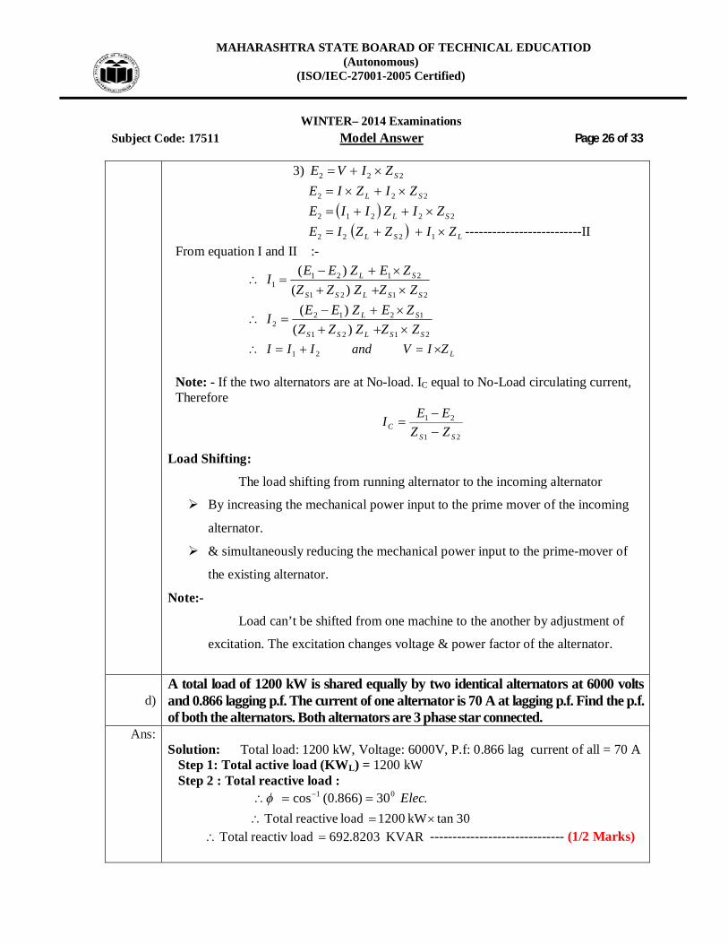
d) A total load of 1200 kW is shared equally by two identical alternators at 6000 volts and 0.866 lagging p.f. The current of one alternator is 70 A at lagging p.f. Find the p.f. of both the alternators. Both alternators are 3 phase star connected.
Ans: Solution: Total load: 1200 kW, Voltage: 6000V, P.f: 0.866 lag current of all = 70 A Step 1: Total active load (KWL) = 1200 kW Step 2 : Total reactive load : .30)866.0(cos 01 Elec 30tankW1200loadreactiveTotal
KVAR8203.692loadreactivTotal ------------------------------ (1/2 Marks)

MAHARASHTRA STATE BOARAD OF TECHNICAL EDUCATIOD (Autonomous)
(ISO/IEC-27001-2005 Certified)
WINTER– 2014 Examinations
Subject Code: 17511 Model Answer Page 27 of 33
Step 3: Reactive Power shared by alternator 1: 11 tan P ------------------------------------------- (1/2 Marks)
CosIVP LL 31
]3
[11
LL IVPCos
-------------------------- (1/2 Marks)
]7060003
10600[3
11
Cos
)431.34(11 Cos
lagCos 8247.01 -------------------------------- (1/2 Marks)
Reactive power shared by alternator 1 = )4331.34(tan600
= KVAR3379.411 ----------- (1/2 Marks)
Step 4: Reactive Power shared by alternator 2 = Total reactive – Reactive power of
alt 1 = 692.8203 – 411.3379
Reactive Power shared by alternator 2 = 281.4824 KVAR----- (1/2 Marks)
But,
Reactive power shared by alternator 2 = 21 tan P
281.4824 = 2tan600 ------ (1/2 Marks)
600
4824.281tan 2
4691.0tan 2
)4691.0(tan 12
02 1331.25
02 9053.0Cos ---------------------- (1/2 Marks)

MAHARASHTRA STATE BOARAD OF TECHNICAL EDUCATIOD (Autonomous)
(ISO/IEC-27001-2005 Certified)
WINTER– 2014 Examinations
Subject Code: 17511 Model Answer Page 28 of 33
OR student may write this way
Step 1: Total active load (KWL) = 1200 kW is shared equally by two indicate alternators 1 & 2
figure is not compulsory The load current shared alternator 1 = I1= 70 Amp
1
11 3
cosIV
KW
T
---------------------------------------- (1/2 Marks)
7060003
10600cos3
1
lagalternatorfactorPower 825.0cos 1 ----------------------------- (1/2 Marks)
.43.34)825.0(cos 011 Elec ---------------------- (1/2 Marks)
.tan)()('')( 1OAlBFlAEllength
43.34tan60011 kWalternatorofKVAR
RKVAKVAR 3.4111 ----------------------------------- (1 /2Marks)
.tan)('')( LOBlloadofKVABDllength
.30)866.0(cos 01 ElecL
30tan1200 kWKVAR L
RKVAKVAR L 82.692 --------------------------------------- (1/2 Marks)
3.41182.692)()()( BFlBDlFDlalternatorofKVAR
52.2812 KVAR ------------------------------------ (1/2 Marks)

MAHARASHTRA STATE BOARAD OF TECHNICAL EDUCATIOD (Autonomous)
(ISO/IEC-27001-2005 Certified)
WINTER– 2014 Examinations
Subject Code: 17511 Model Answer Page 29 of 33
RAEFD is the power triangle of alternator No.2:
47.0)()(tan 2
EFlFDl
---------------------------------------- (1/2 Marks)
)47.0(tan 12
17.252
2..2 alternatoroffPCos
lagalternatorfactorPower 91.0cos 2 ---------------------------- (1/2 Marks)
e) Explain the principle of operation of linear induction motor. Ans: (Figure- 2 Marks & Principle – 2 Marks)
or Equivalent fig. Principle of operation linear induction motor:-
In a sector IM, if sector is made flat and squirrel cage winding is brought to
it we get linear I.M. In practice instead of a flat squirrel cage winding, aluminum or
copper or iron plate is used as rotor.
The flat stator produces a flux that moves in a straight line from its one end to
other at a linear synchronous speed given by Vs = 2 wf
Where, Vs = linear synchronous speed in m/sec
w = width of one pitch in m.
f = supply frequency (Hz)
The speed does not depends on number of poles but only on the poles pitch
and supply frequency. As the flux move linearly it drags the rotor plate along with it
in same direction. However in much practical application the rotor is stationary
while stator moves.

MAHARASHTRA STATE BOARAD OF TECHNICAL EDUCATIOD (Autonomous)
(ISO/IEC-27001-2005 Certified)
WINTER– 2014 Examinations
Subject Code: 17511 Model Answer Page 30 of 33
f) What is an induction generator? State its principle of operation Ans: Induction generator: (2 Mark)
When rotor of induction motor runs faster than synchronous speed, induction
motor runs as generator and called as induction generator. It converts mechanical
energy it receives from the shaft into electrical energy which is released by stator.
However, for creating its own magnetic field, it absorbs reactive power Q from the lime
to which it is connected. The reactive power is supplied by a capacitor bank connected
at the induction generator output terminals.
Figure:- (Figure- 1 Marks & Principle – 1 Marks)
or Equivalent fig. The principle of operation induction Generator:
When rotor of induction motor runs faster than synchronous speed (N>Ns), induction motor runs as generator and called as induction generator. It converts mechanical energy it receives from the shaft into electrical energy which is released by stator. However, for creating its own magnetic field, it absorbs reactive power Q from the line to which it is connected. The reactive power is supplied by a capacitor bank connected at the induction generator output terminals.
MAHARASHTRA STATE BOARAD OF TECHNICAL EDUCATIOD (Autonomous)
(ISO/IEC-27001-2005 Certified)
WINTER– 2014 Examinations
Subject Code: 17511 Model Answer Page 31 of 33 Q.6 Attempt any four of the following : 16 Marks
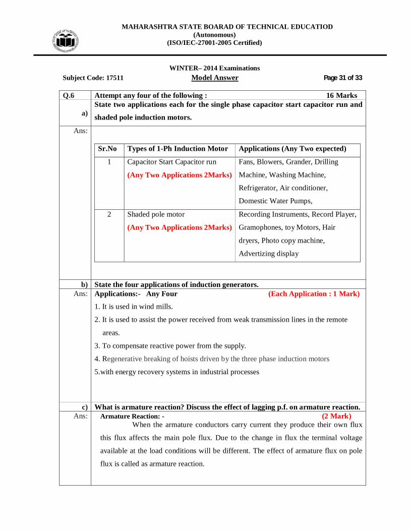
a) State two applications each for the single phase capacitor start capacitor run and
shaded pole induction motors.
Ans: Sr.No Types of 1-Ph Induction Motor Applications (Any Two expected)
1 Capacitor Start Capacitor run
(Any Two Applications 2Marks)
Fans, Blowers, Grander, Drilling
Machine, Washing Machine,
Refrigerator, Air conditioner,
Domestic Water Pumps,
2 Shaded pole motor
(Any Two Applications 2Marks)
Recording Instruments, Record Player,
Gramophones, toy Motors, Hair
dryers, Photo copy machine,
Advertizing display
b) State the four applications of induction generators. Ans: Applications:- Any Four (Each Application : 1 Mark)
1. It is used in wind mills.
2. It is used to assist the power received from weak transmission lines in the remote
areas.
3. To compensate reactive power from the supply.
4. Regenerative breaking of hoists driven by the three phase induction motors
5.with energy recovery systems in industrial processes
c) What is armature reaction? Discuss the effect of lagging p.f. on armature reaction.
Ans: Armature Reaction: - (2 Mark) When the armature conductors carry current they produce their own flux
this flux affects the main pole flux. Due to the change in flux the terminal voltage
available at the load conditions will be different. The effect of armature flux on pole
flux is called as armature reaction.

MAHARASHTRA STATE BOARAD OF TECHNICAL EDUCATIOD (Autonomous)
(ISO/IEC-27001-2005 Certified)
WINTER– 2014 Examinations
Subject Code: 17511 Model Answer Page 32 of 33
The effect of armature reaction depends upon power factor the load:
For lagging P.f. or inductive load: - In this case the armature flux opposes the main flux. This effect is called as de-magnetizing Effect. Due to this, the main flux will be weakened and terminal voltage drops ie EVT .---------(2 Mark)
d) Explain the role of capacitor in a single phase capacitor start capacitor run induction motor
Ans:
(Figure -2 Mark & Explanation -2 Mark)
OR or Equivalent fig
In these motors one capacitor is connected in series with the auxiliary
winding. There is no centrifugal switch. Thus this winding along with the capacitor
remains energized for both starting and running conditions. Capacitor used serves the
purpose of obtaining necessary phase displacement at the time of starting and also
improves the power factor of the motor.
Due to capacitor motor operation becomes salient

MAHARASHTRA STATE BOARAD OF TECHNICAL EDUCATIOD (Autonomous)
(ISO/IEC-27001-2005 Certified)
WINTER– 2014 Examinations
Subject Code: 17511 Model Answer Page 33 of 33
e) With neat schematic diagram, briefly explain the principle of operation of a shaded pole single phase induction motor.
Ans: i) Shaded Pole Induction Motor : (Figure-2 Mark & Explanation: 2 Mark)
or
Equivalent Fig.
Correct diagram of pole axis shifting from left to right
Working:-
When single phase supply is applied across the stator winding an alternating field is created. The flux distribution is non uniform due to shading coils on the poles.
Now consider three different instants of time t1, t2, t3 of the flux wave to examine the effect of shading coil as shown in the fig above. The magnetic neutral axis shifts from left to right in every half cycle, from non shaded area of pole to the shaded area of the pole. This gives to some extent a rotating field effect which may be sufficient to provide starting torque to squirrel cage rotor.