
Subj: MARPOL ANNEX VI INTERNATIONAL ENERGY 16715 · Subj: MARPOL ANNEX VI INTERNATIONAL ENERGY...
57
Transcript of Subj: MARPOL ANNEX VI INTERNATIONAL ENERGY 16715 · Subj: MARPOL ANNEX VI INTERNATIONAL ENERGY...

Subj: MARPOL ANNEX VI INTERNATIONAL ENERGY 16715 EFFICIENCY (IEE)CERTIFICATE IMPLEMENTATION CG-CVC-1 GUIDANCE Policy Letter 13-02
May 5, 2013
2
4. Background. On July 15, 2011, the International Maritime Organization formally adopted Resolution MEPC.203(62), which amends MARPOL Annex VI. The requirements of MEPC.203(62) entered into force on January 1, 2013. The requirements of Annex VI Chapter 4 apply to any ship of 400 gross tonnage or more that engages in voyages to ports or offshore terminals under the jurisdiction of other Parties. The list of Parties to Annex VI may be found at http://www.imo.org/About/Conventions/StatusOfConventions/ Pages/Default.aspx under the “Status of Conventions” link. U.S. vessels are not required to obtain an IEE Certificate if they are not engaged in voyages to nations that are party to Annex VI.
5. Definitions. The new MARPOL Annex VI Chapter 4 requires different actions for new and existing ships. The guidelines in enclosure (1) to reference (c) remain valid for purposes of issuance of Annex VI documents to U.S. vessels. The definitions of new and existing ship and major conversion for Chapter 4 purposes are found in MARPOL Annex VI Regulation 2.3:
a. “Existing ship means a ship which is not a new ship.” (Regulation 2.3.22)
b. “New ship means a ship:
.1 for which the building contract is placed on or after 1 July 2013; or
.2 in the absence of a building contract, the keel of which is laid or which is at a similar stage of construction on or after 1 July 2013; or
.3 the delivery of which is on or after 1 July 2015.” (Regulation 2.3.23)
c. “Major conversion means in relation to Chapter 4 a conversion of a ship:
.1 which substantially alters the dimensions, carrying capacity or engine power of the ship; or
.2 which changes the type of the ship; or
.3 the intent of which in the opinion of the administration is substantially to prolong the life of the ship; or
.4 which otherwise so alters the ship that, if it were a new ship, it would become subject to relevant provisions of the present Convention not applicable to it as an existing ship; or
.5 which substantially alters the energy efficiency of the ship and includes any modifications that could cause the ship to exceed the applicable required EEDI as set out in regulation 21.” (Regulation 2.3.24)

Subj: MARPOL ANNEX VI INTERNATIONAL ENERGY 16715 EFFICIENCY (IEE)CERTIFICATE IMPLEMENTATION CG-CVC-1 GUIDANCE Policy Letter 13-02
May 5, 2013
3
6. Energy efficiency requirements for existing U.S. flagged ships. For existing ships the IEE Certificate is to be issued on the first intermediate or renewal survey for the IAPP Certificate (whichever comes first) on or after January 1, 2013 provided the SEEMP is on board. The SEEMP may be part of the Safety Management System (SMS) (see Regulation 22.1). The SEEMP itself does not have to be approved by the Coast Guard or RCS but must follow the guidelines for preparation of a SEEMP in enclosure (1) (see Regulation 22.2 and 33 U.S.C. § 1908). Once issued the IEE Certificate is valid for the life of the ship unless the ship is withdrawn from service, undergoes a major conversion as defined in Annex VI Regulation 2, or is transferred to the flag of another State (see Regulations 9.10 and 9.11).
7. Energy efficiency requirements for new U.S. flagged ships, new U.S. flagged ships that undergo a major conversion, and existing U.S. flagged ships that undergo a major conversion.
a. EEDI: New Annex VI Regulations 20 and 21 require an Energy Efficiency Design Index (EEDI) for (1) new ships, (2) new ships when they undergo a major conversion, and (3) existing ships that undergo a major conversion after January 1, 2013, so extensive that it is regarded as a newly constructed ship. Based on the definition of “major conversion” it is possible for a new ship to undergo a major conversion that alters the energy efficiency of the post-conversion ship, and as such a new EEDI must be determined. In keeping with reference (a), only certain types of vessels defined in MARPOL Annex VI Regulation 2.25 to 2.35 are required to have an EEDI calculated at this time (see Regulation 21.1). These ship types are: bulk carriers, gas carriers, tankers, containerships, general cargo ships, refrigerated cargo carriers and combination carriers. The definitions of these ship types are located in MARPOL Annex VI Regulations 2.25 to 2.31. Enclosure (2) provides guidance to vessel owners and designers regarding the calculation of the EEDI.
b. SEEMP: In addition to the EEDI requirement new ships or ships that undergo a major conversion are also required to maintain a SEEMP as described for existing ships.
8. Issuance of IEE Certificates for U.S. flagged ships. On December 10, 2012, the Coast Guard published a final rule to amend 46 CFR 8.320. That rule, which became effective January 9, 2013, allows RCS to apply to issue IEE Certificates on behalf of the Coast Guard (see 77 FR 73334, December 10, 2012). We anticipate that RCS that applied to issue IAPP Certificates will also apply to issue IEE Certificates.
a. Existing U.S. flagged vessels. For existing U.S. flagged vessels the IEE Certificate will be issued by the RCS or OCMI that issued the IAPP. The verification of the SEEMP is the sole survey item for IEE Certificate issuance.
b. New U.S. flagged ships, new U.S. flagged ships that undergo a major conversion, and existing U.S. flagged ships that undergo a major conversion. For new U.S. flagged ships, new U.S. flagged ships that undergo a major conversion, and existing U.S.

Subj: MARPOL ANNEX VI INTERNATIONAL ENERGY 16715 EFFICIENCY (IEE)CERTIFICATE IMPLEMENTATION CG-CVC-1 GUIDANCE Policy Letter 13-02
May 5, 2013
4
flagged ships that undergo a major conversion, EEDI review and approval will not be completed directly by the Coast Guard. Owners or designers of new U.S. flagged ships, new U.S. flagged ships that undergo a major conversion, and existing U.S. flagged ships that undergo a major conversion should arrange with a RCS for EEDI review and approval. The attained EEDI will be specific to each ship and will indicate the estimated performance of the ship in terms of energy efficiency, and be accompanied by the EEDI technical file that contains the information necessary for the calculation of the attained EEDI and that shows the process of calculation. The attained EEDI should be provided by the ship owner following the guidelines in enclosure (2) to the RCS for purposes of precertification. The RCS will conduct a survey to verify the attained EEDI based on the guidelines in enclosure (3) and the EEDI technical file. If the results of the sea trial are inconsistent with the preliminary contents of the EEDI technical file, the ship owner or designer may be required to revise the EEDI technical file prior to issuance of the IEE Certificate. Following the final verification of the EEDI technical file and SEEMP, a Record of Construction Relating to Energy Efficiency (Supplement to the IEE Certificate) and IEE Certificate will be issued (see Annex VI Appendix VIII).
9. Exemptions/Waivers. Vessels using diesel-electric, turbine or hybrid propulsion systems are exempt from the requirements to prepare an EEDI technical file and obtain an IEE Supplement regardless of build date (see Regulation 19.3). In addition, the Coast Guard may waive the requirements for new ships to prepare an EEDI technical file and obtain an IEE Supplement in certain cases described in Annex VI Regulation 19. RCS will submit requests for waivers directly to CG-CVC-1 (see 46 CFR 46 CFR 8.130 (a)(13)). In addition, the Coast Guard, in consultation with the Environmental Protection Agency may approve a U.S. flag ship for a MARPOL Annex VI Regulation 3 trial program exemption or Regulation 4 equivalence.
10. Foreign Ships. Coast Guard Port State Control examiners should verify the IEE Certificate and SEEMP when checking the validity of the IAPP Certificate during port state control exams. The SEEMP does not require flag administration or classification society approval but must be on board (see Regulation 22.1). Port State Control Examiners should keep in mind that an IEE Certificate may not have been issued if the IAPP intermediate/renewal survey has not yet been performed for that vessel.
11. Disclaimer. Neither this guidance nor reference (c) is a substitute for applicable legal requirements, nor a rule. Neither is intended to nor does impose legally-binding requirements on any party. This guidance and reference (c) represent the Coast Guard’s current thinking on this topic and may assist industry, mariners, the general public, and the Coast Guard, as well as other Federal and state regulators, in applying statutory and regulatory requirements. An alternative approach may be used for complying with these requirements if the approach satisfies the requirements of the applicable statutes and regulations. If you want to discuss an alternative approach, you may contact the Coast Guard

Subj: MARPOL ANNEX VI INTERNATIONAL ENERGY 16715 EFFICIENCY (IEE)CERTIFICATE IMPLEMENTATION CG-CVC-1 GUIDANCE Policy Letter 13-02
May 5, 2013
5
Office of Commercial Vessel Compliance (CG-CVC-1) who is responsible for implementing this policy.
12. Questions. Questions concerning this policy and guidance should be directed to COMDT (CG-CVC-1), Office of Commercial Vessel Compliance, at [email protected]. This policy and other Domestic Vessel Policy documents are posted on Homeport at http://homeport.uscg.mil/USvsls.
#
Enclosures: (1) IMO Resolution MEPC.213(63), 2012 Guidelines for Preparation of a SEEMP (2) IMO Resolution MEPC.212(63), 2012 Guidelines on the Method of Calculation
of the Attained EEDI for New Ships (3) IMO Resolution MEPC.214(63), 2012 Guidelines on Survey and Certification
of the EEDI

MEPC 63/23 Annex 9, page 1
I:\MEPC\63\23.doc
ANNEX 9
RESOLUTION MEPC.213(63)
Adopted on 2 March 2012
2012 GUIDELINES FOR THE DEVELOPMENT OF A SHIP ENERGY EFFICIENCY MANAGEMENT PLAN (SEEMP)
THE MARINE ENVIRONMENT PROTECTION COMMITTEE, RECALLING article 38(a) of the Convention on the International Maritime Organization concerning the functions of the Marine Environment Protection Committee (the Committee) conferred upon it by international conventions for the prevention and control of marine pollution, RECALLING ALSO that, at its sixty-second session, the Committee adopted, by resolution MEPC.203(62), amendments to the Annex of the Protocol of 1997 to amend the International Convention for the Prevention of Pollution from Ships, 1973, as modified by the Protocol of 1978 relating thereto (inclusion of regulations on energy efficiency for ships in MARPOL Annex VI), NOTING the amendments to MARPOL Annex VI adopted at its sixty-second session by inclusion of a new chapter 4 for regulations on energy efficiency for ships, are expected to enter into force on 1 January 2013 upon their acceptance on 1 July 2012, NOTING ALSO that regulation 22 of MARPOL Annex VI, as amended, requires each ship to keep on board a ship specific Ship Energy Efficiency Management Plan taking into account guidelines developed by the Organization, RECOGNIZING that the amendments to MARPOL Annex VI requires the adoption of relevant guidelines for smooth and uniform implementation of the regulations and to provide sufficient lead time for industry to prepare, HAVING CONSIDERED, at its sixty-third session, the draft 2012 Guidelines for the development of a Ship Energy Efficiency Management Plan (SEEMP), 1. ADOPTS the 2012 Guidelines for the development of a Ship Energy Efficiency Management Plan (SEEMP), as set out at annex to the present resolution; 2. INVITES Administrations to take the annexed Guidelines into account when developing and enacting national laws which give force to and implement provisions set forth in regulation 22 of MARPOL Annex VI, as amended; 3. REQUESTS the Parties to MARPOL Annex VI and other Member Governments to bring the annexed Guidelines related to the Ship Energy Efficiency Management Plan (SEEMP) to the attention of masters, seafarers, shipowners, ship operators and any other interested groups; 4. AGREES to keep these Guidelines under review in light of the experience gained; and 5. REVOKES the Guidance circulated by MEPC.1/Circ.683, as from this date.
MEPC 63/23 Annex 9, page 2
I:\MEPC\63\23.doc
ANNEX
2012 GUIDELINES FOR THE DEVELOPMENT OF A SHIP ENERGY EFFICIENCY MANAGEMENT PLAN (SEEMP)
CONTENTS
1 INTRODUCTION 2 DEFINITIONS 3 GENERAL 4 FRAMEWORK AND STRUCTURE OF THE SEEMP 5 GUIDANCE ON BEST PRACTICES FOR FUEL-EFFICIENT OPERATION
OF SHIPS APPENDIX – A SAMPLE FORM OF A SHIP ENERGY EFFICIENCY MANAGEMENT PLAN
(SEEMP)

MEPC 63/23 Annex 9, page 3
I:\MEPC\63\23.doc
1 INTRODUCTION 1.1 These Guidelines have been developed to assist with the preparation of Ship Energy Efficiency Management Plan (hereafter referred to as the "SEEMP") that are required by regulation 22 of Annex VI of the International Convention for the Prevention of Pollution from Ships, 1973, as modified by the Protocol of 1978 relating thereto (MARPOL 73/78) (hereafter referred to as the "Convention"). 1.2 A SEEMP provides a possible approach for monitoring ship and fleet efficiency performance over time and some options to be considered when seeking to optimize the performance of the ship. 1.3 These Guidelines should be used primarily by ships' masters, operators and owners in order to develop the SEEMP. 1.4 A sample form of a SEEMP is presented in the appendix for illustrative purposes. 2 DEFINITIONS 2.1 For the purpose of these Guidelines, the definitions in the Annex VI of the Convention apply. 2.2 "Company" means the owner of the ship or any other organization of person such as the manager, or the bareboat charterer, who has assumed the responsibility for operation of the ship from the shipowner. 2.3 "Safety Management system" means a structured and documented system enabling company personnel to implement effectively the company safety and environmental protection policy, as defined in paragraph 1.1 of International Safety Management Code. 3 GENERAL 3.1 In global terms it should be recognized that operational efficiencies delivered by a large number of ship operators will make an invaluable contribution to reducing global carbon emissions. 3.2 The purpose of a SEEMP is to establish a mechanism for a company and/or a ship to improve the energy efficiency of a ship's operation. Preferably, the ship-specific SEEMP is linked to a broader corporate energy management policy for the company that owns, operates or controls the ship, recognizing that no two shipping companies are the same, and that ships operate under a wide range of different conditions. 3.3 Many companies will already have an environmental management system (EMS) in place under ISO 14001 which contains procedures for selecting the best measures for particular vessels and then setting objectives for the measurement of relevant parameters, along with relevant control and feedback features. Monitoring of operational environmental efficiency should therefore be treated as an integral element of broader company management systems. 3.4 In addition, many companies already develop, implement and maintain a Safety Management System. In such case, the SEEMP may form part of the ship's Safety Management System.
MEPC 63/23 Annex 9, page 4
I:\MEPC\63\23.doc
3.5 This document provides guidance for the development of a SEEMP that should be adjusted to the characteristics and needs of individual companies and ships. The SEEMP is intended to be a management tool to assist a company in managing the ongoing environmental performance of its vessels and as such, it is recommended that a company develops procedures for implementing the plan in a manner which limits any onboard administrative burden to the minimum necessary. 3.6 The SEEMP should be developed as a ship-specific plan by the company. The SEEMP seeks to improve a ship's energy efficiency through four steps: planning, implementation, monitoring, and self-evaluation and improvement. These components play a critical role in the continuous cycle to improve ship energy management. With each iteration of the cycle, some elements of the SEEMP will necessarily change while others may remain as before. 3.7 At all times safety considerations should be paramount. The trade a ship is engaged in may determine the feasibility of the efficiency measures under consideration. For example, ships that perform services at sea (pipe laying, seismic survey, OSVs, dredgers, etc.) may choose different methods of improving energy efficiency when compared to conventional cargo carriers. The length of voyage may also be an important parameter as may trade specific safety considerations. 4 FRAMEWORK AND STRUCTURE OF THE SEEMP 4.1 Planning 4.1.1 Planning is the most crucial stage of the SEEMP, in that it primarily determines both the current status of ship energy usage and the expected improvement of ship energy efficiency. Therefore, it is encouraged to devote sufficient time to planning so that the most appropriate, effective and implementable plan can be developed. Ship-specific measures 4.1.2 Recognizing that there are a variety of options to improve efficiency – speed optimization, weather routeing and hull maintenance, for example – and that the best package of measures for a ship to improve efficiency differs to a great extent depending upon ship type, cargoes, routes and other factors, the specific measures for the ship to improve energy efficiency should be identified in the first place. These measures should be listed as a package of measures to be implemented, thus providing the overview of the actions to be taken for that ship. 4.1.3 During this process, therefore, it is important to determine and understand the ship's current status of energy usage. The SEEMP then identifies energy-saving measures that have been undertaken, and determines how effective these measures are in terms of improving energy efficiency. The SEEMP also identifies what measures can be adopted to further improve the energy efficiency of the ship. It should be noted, however, that not all measures can be applied to all ships, or even to the same ship under different operating conditions and that some of them are mutually exclusive. Ideally, initial measures could yield energy (and cost) saving results that then can be reinvested into more difficult or expensive efficiency upgrades identified by the SEEMP. 4.1.4 Guidance on Best Practices for Fuel-Efficient Operation of Ships set out in chapter 5, can be used to facilitate this part of the planning phase. Also, in the planning process, particular consideration should be given to minimize any onboard administrative burden.

MEPC 63/23 Annex 9, page 5
I:\MEPC\63\23.doc
Company-specific measures 4.1.5 The improvement of energy efficiency of ship operation does not necessarily depend on single ship management only. Rather, it may depend on many stakeholders including ship repair yards, shipowners, operators, charterers, cargo owners, ports and traffic management services. For example, "Just in time" – as explained in 5.5 – requires good early communication among operators, ports and traffic management service. The better coordination among such stakeholders is, the more improvement can be expected. In most cases, such coordination or total management is better made by a company rather than by a ship. In this sense, it is recommended that a company also establish an energy management plan to manage its fleet (should it not have one in place already) and make necessary coordination among stakeholders. Human resource development 4.1.6 For effective and steady implementation of the adopted measures, raising awareness of and providing necessary training for personnel both on shore and on board are an important element. Such human resource development is encouraged and should be considered as an important component of planning as well as a critical element of implementation. Goal setting 4.1.7 The last part of planning is goal setting. It should be emphasized that the goal setting is voluntary, that there is no need to announce the goal or the result to the public, and that neither a company nor a ship are subject to external inspection. The purpose of goal setting is to serve as a signal which involved people should be conscious of, to create a good incentive for proper implementation, and then to increase commitment to the improvement of energy efficiency. The goal can take any form, such as the annual fuel consumption or a specific target of Energy Efficiency Operational Indicator (EEOI). Whatever the goal is, the goal should be measurable and easy to understand. 4.2 Implementation Establishment of implementation system 4.2.1 After a ship and a company identify the measures to be implemented, it is essential to establish a system for implementation of the identified and selected measures by developing the procedures for energy management, by defining tasks and by assigning them to qualified personnel. Thus, the SEEMP should describe how each measure should be implemented and who the responsible person(s) is. The implementation period (start and end dates) of each selected measure should be indicated. The development of such a system can be considered as a part of planning, and therefore may be completed at the planning stage. Implementation and record-keeping 4.2.2 The planned measures should be carried out in accordance with the predetermined implementation system. Record-keeping for the implementation of each measure is beneficial for self-evaluation at a later stage and should be encouraged. If any identified measure cannot be implemented for any reason(s), the reason(s) should be recorded for internal use.
MEPC 63/23 Annex 9, page 6
I:\MEPC\63\23.doc
4.3 Monitoring Monitoring tools 4.3.1 The energy efficiency of a ship should be monitored quantitatively. This should be done by an established method, preferably by an international standard. The EEOI developed by the Organization is one of the internationally established tools to obtain a quantitative indicator of energy efficiency of a ship and/or fleet in operation, and can be used for this purpose. Therefore, EEOI could be considered as the primary monitoring tool, although other quantitative measures also may be appropriate. 4.3.2 If used, it is recommended that the EEOI is calculated in accordance with the Guidelines developed by the Organization (MEPC.1/Circ.684), adjusted, as necessary, to a specific ship and trade. 4.3.3 In addition to the EEOI, if convenient and/or beneficial for a ship or a company, other measurement tools can be utilized. In the case where other monitoring tools are used, the concept of the tool and the method of monitoring may be determined at the planning stage. Establishment of monitoring system 4.3.4 It should be noted that whatever measurement tools are used, continuous and consistent data collection is the foundation of monitoring. To allow for meaningful and consistent monitoring, the monitoring system, including the procedures for collecting data and the assignment of responsible personnel, should be developed. The development of such a system can be considered as a part of planning, and therefore should be completed at the planning stage. 4.3.5 It should be noted that, in order to avoid unnecessary administrative burdens on ships' staff, monitoring should be carried out as far as possible by shore staff, utilizing data obtained from existing required records such as the official and engineering log-books and oil record books, etc. Additional data could be obtained as appropriate. Search and Rescue 4.3.6 When a ship diverts from its scheduled passage to engage in search and rescue operations, it is recommended that data obtained during such operations is not used in ship energy efficiency monitoring, and that such data may be recorded separately. 4.4 Self-evaluation and improvement 4.4.1 Self-evaluation and improvement is the final phase of the management cycle. This phase should produce meaningful feedback for the coming first stage, i.e. planning stage of the next improvement cycle. 4.4.2 The purpose of self-evaluation is to evaluate the effectiveness of the planned measures and of their implementation, to deepen the understanding on the overall characteristics of the ship's operation such as what types of measures can/cannot function effectively, and how and/or why, to comprehend the trend of the efficiency improvement of that ship and to develop the improved SEEMP for the next cycle.
MEPC 63/23 Annex 9, page 7
I:\MEPC\63\23.doc
4.4.3 For this process, procedures for self-evaluation of ship energy management should be developed. Furthermore, self-evaluation should be implemented periodically by using data collected through monitoring. In addition, it is recommended to invest time in identifying the cause-and-effect of the performance during the evaluated period for improving the next stage of the management plan. 5 GUIDANCE ON BEST PRACTICES FOR FUEL-EFFICIENT OPERATION OF
SHIPS 5.1 The search for efficiency across the entire transport chain takes responsibility beyond what can be delivered by the owner/operator alone. A list of all the possible stakeholders in the efficiency of a single voyage is long; obvious parties are designers, shipyards and engine manufacturers for the characteristics of the ship, and charterers, ports and vessel traffic management services, etc., for the specific voyage. All involved parties should consider the inclusion of efficiency measures in their operations both individually and collectively. Fuel-Efficient Operations Improved voyage planning 5.2 The optimum route and improved efficiency can be achieved through the careful planning and execution of voyages. Thorough voyage planning needs time, but a number of different software tools are available for planning purposes. 5.3 IMO resolution A.893(21) (25 November 1999) on "Guidelines for voyage planning" provides essential guidance for the ship's crew and voyage planners. Weather routeing 5.4 Weather routeing has a high potential for efficiency savings on specific routes. It is commercially available for all types of ship and for many trade areas. Significant savings can be achieved, but conversely weather routeing may also increase fuel consumption for a given voyage. Just in time 5.5 Good early communication with the next port should be an aim in order to give maximum notice of berth availability and facilitate the use of optimum speed where port operational procedures support this approach. 5.6 Optimized port operation could involve a change in procedures involving different handling arrangements in ports. Port authorities should be encouraged to maximize efficiency and minimize delay. Speed optimization 5.7 Speed optimization can produce significant savings. However, optimum speed means the speed at which the fuel used per tonne mile is at a minimum level for that voyage. It does not mean minimum speed; in fact, sailing at less than optimum speed will consume more fuel rather than less. Reference should be made to the engine manufacturer's power/consumption curve and the ship's propeller curve. Possible adverse consequences of slow speed operation may include increased vibration and problems with soot deposits in combustion chambers and exhaust systems. These possible consequences should be taken into account.

MEPC 63/23 Annex 9, page 8
I:\MEPC\63\23.doc
5.8 As part of the speed optimization process, due account may need to be taken of the need to coordinate arrival times with the availability of loading/discharge berths, etc. The number of ships engaged in a particular trade route may need to be taken into account when considering speed optimization. 5.9 A gradual increase in speed when leaving a port or estuary whilst keeping the engine load within certain limits may help to reduce fuel consumption. 5.10 It is recognized that under many charter parties the speed of the vessel is determined by the charterer and not the operator. Efforts should be made when agreeing charter party terms to encourage the ship to operate at optimum speed in order to maximize energy efficiency. Optimized shaft power 5.11 Operation at constant shaft RPM can be more efficient than continuously adjusting speed through engine power (see paragraph 5.7). The use of automated engine management systems to control speed rather than relying on human intervention may be beneficial. Optimized ship handling Optimum trim 5.12 Most ships are designed to carry a designated amount of cargo at a certain speed for a certain fuel consumption. This implies the specification of set trim conditions. Loaded or unloaded, trim has a significant influence on the resistance of the ship through the water and optimizing trim can deliver significant fuel savings. For any given draft there is a trim condition that gives minimum resistance. In some ships, it is possible to assess optimum trim conditions for fuel efficiency continuously throughout the voyage. Design or safety factors may preclude full use of trim optimization. Optimum ballast 5.13 Ballast should be adjusted taking into consideration the requirements to meet optimum trim and steering conditions and optimum ballast conditions achieved through good cargo planning. 5.14 When determining the optimum ballast conditions, the limits, conditions and ballast management arrangements set out in the ship's Ballast Water Management Plan are to be observed for that ship. 5.15 Ballast conditions have a significant impact on steering conditions and autopilot settings and it needs to be noted that less ballast water does not necessarily mean the highest efficiency. Optimum propeller and propeller inflow considerations 5.16 Selection of the propeller is normally determined at the design and construction stage of a ship's life but new developments in propeller design have made it possible for retrofitting of later designs to deliver greater fuel economy. Whilst it is certainly for consideration, the propeller is but one part of the propulsion train and a change of propeller in isolation may have no effect on efficiency and may even increase fuel consumption.

MEPC 63/23 Annex 9, page 9
I:\MEPC\63\23.doc
5.17 Improvements to the water inflow to the propeller using arrangements such as fins and/or nozzles could increase propulsive efficiency power and hence reduce fuel consumption. Optimum use of rudder and heading control systems (autopilots) 5.18 There have been large improvements in automated heading and steering control systems technology. Whilst originally developed to make the bridge team more effective, modern autopilots can achieve much more. An integrated Navigation and Command System can achieve significant fuel savings by simply reducing the distance sailed "off track". The principle is simple; better course control through less frequent and smaller corrections will minimize losses due to rudder resistance. Retrofitting of a more efficient autopilot to existing ships could be considered. 5.19 During approaches to ports and pilot stations the autopilot cannot always be used efficiently as the rudder has to respond quickly to given commands. Furthermore at certain stage of the voyage it may have to be deactivated or very carefully adjusted, i.e. heavy weather and approaches to ports. 5.20 Consideration may be given to the retrofitting of improved rudder blade design (e.g. "twist-flow" rudder). Hull maintenance 5.21 Docking intervals should be integrated with ship operator's ongoing assessment of ship performance. Hull resistance can be optimized by new technology-coating systems, possibly in combination with cleaning intervals. Regular in-water inspection of the condition of the hull is recommended. 5.22 Propeller cleaning and polishing or even appropriate coating may significantly increase fuel efficiency. The need for ships to maintain efficiency through in-water hull cleaning should be recognized and facilitated by port States. 5.23 Consideration may be given to the possibility of timely full removal and replacement of underwater paint systems to avoid the increased hull roughness caused by repeated spot blasting and repairs over multiple dockings. 5.24 Generally, the smoother the hull, the better the fuel efficiency. Propulsion system 5.25 Marine diesel engines have a very high thermal efficiency (~50%). This excellent performance is only exceeded by fuel cell technology with an average thermal efficiency of 60 per cent. This is due to the systematic minimization of heat and mechanical loss. In particular, the new breed of electronic controlled engines can provide efficiency gains. However, specific training for relevant staff may need to be considered to maximize the benefits. Propulsion system maintenance 5.26 Maintenance in accordance with manufacturers' instructions in the company's planned maintenance schedule will also maintain efficiency. The use of engine condition monitoring can be a useful tool to maintain high efficiency.

MEPC 63/23 Annex 9, page 10
I:\MEPC\63\23.doc
5.27 Additional means to improve engine efficiency might include:
Use of fuel additives; Adjustment of cylinder lubrication oil consumption; Valve improvements; Torque analysis; and Automated engine monitoring systems.
Waste heat recovery 5.28 Waste heat recovery is now a commercially available technology for some ships. Waste heat recovery systems use thermal heat losses from the exhaust gas for either electricity generation or additional propulsion with a shaft motor. 5.29 It may not be possible to retrofit such systems into existing ships. However, they may be a beneficial option for new ships. Shipbuilders should be encouraged to incorporate new technology into their designs. Improved fleet management 5.30 Better utilization of fleet capacity can often be achieved by improvements in fleet planning. For example, it may be possible to avoid or reduce long ballast voyages through improved fleet planning. There is opportunity here for charterers to promote efficiency. This can be closely related to the concept of "just in time" arrivals. 5.31 Efficiency, reliability and maintenance-oriented data sharing within a company can be used to promote best practice among ships within a company and should be actively encouraged. Improved cargo handling 5.32 Cargo handling is in most cases under the control of the port and optimum solutions matched to ship and port requirements should be explored. Energy management 5.33 A review of electrical services on board can reveal the potential for unexpected efficiency gains. However care should be taken to avoid the creation of new safety hazards when turning off electrical services (e.g. lighting). Thermal insulation is an obvious means of saving energy. Also see comment below on shore power. 5.34 Optimization of reefer container stowage locations may be beneficial in reducing the effect of heat transfer from compressor units. This might be combined as appropriate with cargo tank heating, ventilation, etc. The use of water-cooled reefer plant with lower energy consumption might also be considered. Fuel Type 5.35 Use of emerging alternative fuels may be considered as a CO2 reduction method but availability will often determine the applicability.

MEPC 63/23 Annex 9, page 11
I:\MEPC\63\23.doc
Other measures 5.36 Development of computer software for the calculation of fuel consumption, for the establishment of an emissions "footprint", to optimize operations, and the establishment of goals for improvement and tracking of progress may be considered. 5.37 Renewable energy sources, such as wind, solar (or photovoltaic) cell technology, have improved enormously in the recent years and should be considered for onboard application. 5.38 In some ports shore power may be available for some ships but this is generally aimed at improving air quality in the port area. If the shore-based power source is carbon efficient, there may be a net efficiency benefit. Ships may consider using onshore power if available. 5.39 Even wind assisted propulsion may be worthy of consideration. 5.40 Efforts could be made to source fuel of improved quality in order to minimize the amount of fuel required to provide a given power output. Compatibility of measures 5.41 This document indicates a wide variety of possibilities for energy efficiency improvements for the existing fleet. While there are many options available, they are not necessarily cumulative, are often area and trade dependent and likely to require the agreement and support of a number of different stakeholders if they are to be utilized most effectively. Age and operational service life of a ship 5.42 All measures identified in this document are potentially cost-effective as a result of high oil prices. Measures previously considered unaffordable or commercially unattractive may now be feasible and worthy of fresh consideration. Clearly, this equation is heavily influenced by the remaining service life of a ship and the cost of fuel. Trade and sailing area 5.43 The feasibility of many of the measures described in this guidance will be dependent on the trade and sailing area of the vessel. Sometimes ships will change their trade areas as a result of a change in chartering requirements but this cannot be taken as a general assumption. For example, wind-enhanced power sources might not be feasible for short sea shipping as these ships generally sail in areas with high traffic densities or in restricted waterways. Another aspect is that the world's oceans and seas each have characteristic conditions and so ships designed for specific routes and trades may not obtain the same benefit by adopting the same measures or combination of measures as other ships. It is also likely that some measures will have a greater or lesser effect in different sailing areas. 5.44 The trade a ship is engaged in may determine the feasibility of the efficiency measures under consideration. For example, ships that perform services at sea (pipe laying, seismic survey, OSVs, dredgers, etc.) may choose different methods of improving energy efficiency when compared to conventional cargo carriers. The length of voyage may also be an important parameter as may trade specific safety considerations. The pathway to the most efficient combination of measures will be unique to each vessel within each shipping company.


MEPC 63/23 Annex 8, page 1
I:\MEPC\63\23.doc
ANNEX 8
RESOLUTION MEPC.212(63)
Adopted on 2 March 2012
2012 GUIDELINES ON THE METHOD OF CALCULATION OF THE ATTAINED ENERGY EFFICIENCY DESIGN INDEX (EEDI) FOR NEW SHIPS
THE MARINE ENVIRONMENT PROTECTION COMMITTEE, RECALLING article 38(a) of the Convention on the International Maritime Organization concerning the functions of the Marine Environment Protection Committee (the Committee) conferred upon it by international conventions for the prevention and control of marine pollution, RECALLING ALSO that, at its sixty-second session, the Committee adopted, by resolution MEPC.203(62), amendments to the annex of the Protocol of 1997 to amend the International Convention for the Prevention of Pollution from Ships, 1973, as modified by the Protocol of 1978 relating thereto (inclusion of regulations on energy efficiency for ships in MARPOL Annex VI), NOTING the amendments to MARPOL Annex VI adopted at its sixty-second session by inclusion of a new chapter 4 for regulations on energy efficiency for ships, are expected to enter into force on 1 January 2013 upon their acceptance on 1 July 2012, NOTING ALSO that regulation 20 (Attained EEDI) of MARPOL Annex VI, as amended, requires that the Energy Efficiency Design Index shall be calculated taking into account the guidelines developed by the Organization, RECOGNIZING that the amendments to MARPOL Annex VI requires the adoption of relevant guidelines for smooth and uniform implementation of the regulations and to provide sufficient lead time for industry to prepare, HAVING CONSIDERED, at its sixty-third session, the draft 2012 Guidelines on the method of calculation of the attained Energy Efficiency Design Index (EEDI) for new ships, 1. ADOPTS the 2012 Guidelines on the method of calculation of the attained Energy Efficiency Design Index (EEDI) for new ships, as set out at annex to the present resolution; 2. INVITES Administrations to take the annexed Guidelines into account when developing and enacting national laws which give force to and implement provisions set forth in regulation 20 of MARPOL Annex VI, as amended; 3. REQUESTS the Parties to MARPOL Annex VI and other Member Governments to bring the annexed Guidelines related to the Energy Efficiency Design Index (EEDI) to the attention of shipowners, ship operators, shipbuilders, ship designers and any other interested groups; 4. AGREES to keep these Guidelines under review in light of the experience gained; and 5. REVOKES the Interim Guidelines circulated by MEPC.1/Circ.681, as from this date.
MEPC 63/23 Annex 8, page 2
I:\MEPC\63\23.doc
ANNEX
2012 GUIDELINES ON THE METHOD OF CALCULATION OF THE ATTAINED ENERGY EFFICIENCY DESIGN INDEX (EEDI) FOR NEW SHIPS
CONTENTS 1 Definitions 2 Energy Efficiency Design Index (EEDI) including the equation
2.1 CF ; conversion factor between fuel consumption and CO2 emission 2.2 Vref ; ship speed 2.3 Capacity
2.3.1 Bulk carriers, tankers, gas carriers, ro-ro cargo ships and general cargo ships
2.3.2 Passenger ships and ro-ro passenger ships 2.3.3 Containerships
2.4 Deadweight 2.5 P ; Power of main and auxiliary engines
2.5.1 PME ; power of main engines 2.5.2 PPTO ; shaft generator 2.5.3 PPTI ; shaft motor 2.5.4 Peff ; output of innovative mechanical energy efficient
technology 2.5.5 PAEeff ; auxiliary power reduction 2.5.6 PAE ; power of auxiliary engines
2.6 Vref, Capacity and P 2.7 SFC ; Specific fuel consumption
2.8 fj ; Correction factor for ship specific design elements 2.8.1 fj ; ice-class ships 2.8.2 fj ; shuttle tankers 2.8.3 fj ; other ship types
2.9 fw ; Weather factor 2.10 feff ; Availability factor of innovative energy efficiency technology 2.11 fi ; Capacity factor
2.11.1 fi ; ice-class ships 2.11.2 fi ; ship specific voluntary structural enhancement 2.11.3 fi ; bulk carriers and oil tankers under Common Structural
Rules (CSR) 2.11.4 fi ; other ship types
2.12 fc ; Cubic capacity correction factor 2.12.1 fc ; chemical tankers 2.12.2 fc ; LNG carriers
2.13 Lpp ; Length between perpendiculars
APPENDIX 1 A generic and simplified power plant APPENDIX 2 Guidelines for the development of electric power tables for EEDI
(EPT-EEDI)

MEPC 63/23 Annex 8, page 3
I:\MEPC\63\23.doc
1 Definitions MARPOL means the International Convention for the Prevention of Pollution from Ships, 1973, as modified by the Protocol of 1978 relating thereto, as amended. For the purpose of these Guidelines, the definitions in "REGULATIONS ON ENERGY EFFICIENCY FOR SHIPS" (RESOLUTION MEPC. 203(62)) apply. 2 Energy Efficiency Design Index (EEDI) The attained new ship Energy Efficiency Design Index (EEDI) is a measure of ships energy efficiency (g/t*nm) and calculated by the following formula:
refwci
neff
i
MEFMEieffieffAEFAE
nPTI
i
neff
i
iAEeffieffiPTI
n
j
jAEFAEAEiMEiFME
nME
i
iME
n
j
j
VfCapacityff
SFCCPfSFCCPfPfSFCCPSFCCPf
1
)()(
1 1
)()()(
1
)()(
1
)(
1
* If part of the Normal Maximum Sea Load is provided by shaft generators,
SFCME and CFME may – for that part of the power – be used instead of SFCAE and CFAE
** In case of PPTI(i)>0, the average weighted value of (SFCME . CFME) and
(SFCAE . CFAE ) to be used for calculation of Peff
Note: This formula may not be able to apply to diesel-electric propulsion, turbine
propulsion or hybrid propulsion system. Where:
.1 CF is a non-dimensional conversion factor between fuel consumption
measured in g and CO2 emission also measured in g based on carbon content. The subscripts MEi and AEi refer to the main and auxiliary engine(s) respectively. CF corresponds to the fuel used when determining SFC listed in the applicable test report included in a Technical File as defined in paragraph 1.3.15 of NOx Technical Code ("test report included in a NOx technical file" hereafter). The value of CF is as follows:
Type of fuel Reference Carbon content
CF
(t-CO2/t-Fuel)
1 Diesel/Gas Oil ISO 8217 Grades DMX through DMB
0.8744 3.206
2 Light Fuel Oil (LFO) ISO 8217 Grades RMA through RMD
0.8594 3.151
3 Heavy Fuel Oil (HFO)
ISO 8217 Grades RME through RMK
0.8493 3.114
4 Liquefied Petroleum Gas (LPG)
Propane 0.8182 3.000 Butane 0.8264 3.030
5 Liquefied Natural Gas (LNG)
0.7500 2.750

MEPC 63/23 Annex 8, page 4
I:\MEPC\63\23.doc
.2 Vref is the ship speed, measured in nautical miles per hour (knot), on deep water in the condition corresponding to the Capacity as defined in paragraphs 2.3.1 and 2.3.3 (in case of passenger ships and ro-ro passenger ships, this condition should be summer load draught as provided in paragraph 2.4) at the shaft power of the engine(s) as defined in paragraph 2.5 and assuming the weather is calm with no wind and no waves.
.3 Capacity is defined as follows:
.1 For bulk carriers, tankers, gas tankers, ro-ro cargo ships, general
cargo ships, refrigerated cargo carrier and combination carriers, deadweight should be used as Capacity.
.2 For passenger ships and ro-ro passenger ships, gross tonnage in
accordance with the International Convention of Tonnage Measurement of Ships 1969, Annex I, regulation 3 should be used as Capacity.
.3 For containerships, 70 per cent of the deadweight (DWT) should be used as Capacity. EEDI values for containerships are calculated as follows:
.1 attained EEDI is calculated in accordance with the EEDI
formula using 70 per cent deadweight for Capacity. .2 estimated index value in the Guidelines for calculation of
the reference line is calculated using 70 per cent deadweight as:
ref
NME
iAEiME
V
PPValueIndexEstimated
DWT%70
2151901144.3 1
.3 parameters a and c for containerships in Table 2 of
regulation 21 of MARPOL Annex VI are determined by plotting the estimated index value against 100 per cent deadweight i.e. a=174.22 and c=0.201 were determined.
.4 required EEDI for a new containership is calculated using 100 per cent deadweight as:
Required EEDI = (1-X/100) · a · 100% deadweight –c
Where X is the reduction factor (in percentage) in
accordance with Table 1 in regulation 21 of MARPOL Annex VI relating to the applicable phase and size of new containership.
.4 Deadweight means the difference in tonnes between the displacement of a
ship in water of relative density of 1,025 kg/m3 at the summer load draught and the lightweight of the ship. The summer load draught should be taken as the maximum summer draught as certified in the stability booklet approved by the Administration or an organization recognized by it.

MEPC 63/23 Annex 8, page 5
I:\MEPC\63\23.doc
.5 P is the power of the main and auxiliary engines, measured in kW. The subscripts ME and AE refer to the main and auxiliary engine(s), respectively. The summation on i is for all engines with the number of engines (nME). (See diagram in appendix 1.)
.1 PME(i) is 75 per cent of the rated installed power (MCR*) for each
main engine (i).
The influence of additional shaft power take off or shaft power take in is defined in the following paragraphs.
.2 Shaft generator
In case where shaft generator(s) are installed, PPTO(i) is 75 per cent of the rated electrical output power of each shaft generator.
For calculation of the effect of shaft generators two options are available:
Option 1: .1 The maximum allowable deduction for the calculation of
PME(i) is to be no more than PAE as defined in paragraph 2.5.6. For this case, PME(i) is calculated as:
PME(i) = )()(75.0 iPTOiME PMCR
or Option 2: .2 Where an engine is installed with a higher rated power
output than that which the propulsion system is limited to by verified technical means, then the value of PME(i) is 75 per cent of that limited power for determining the reference speed, Vref and for EEDI calculation.
* The value of MCR specified on the EIAPP certificate should be used for calculation. If the main engines
are not required to have an EIAPP certificate, the MCR on the nameplate should be used.

MEPC 63/23 Annex 8, page 6
I:\MEPC\63\23.doc
The following figure gives guidance for determination of PME(i) :
.3 Shaft motor
In case where shaft motor(s) are installed, PPTI(i) is 75 per cent of the rated power consumption of each shaft motor divided by the weighted average efficiency of the generator(s). The propulsion power at which Vref is measured, is:
ShaftiPTIiME PP ),()(
Where:
GeniPTIiPTIShaftiPTI PP )()(),(
)(iPTI is the efficiency of each shaft motor installed
Gen is the weighted average efficiency of the generator(s)
Where the total propulsion power as defined above is higher than 75 per cent of the power the propulsion system is limited to by verified technical means, then 75 per cent of the limited power is to be used as the total propulsion power for determining the reference speed, Vref and for EEDI calculation.
MEPC 63/23 Annex 8, page 7
I:\MEPC\63\23.doc
In case of combined PTI/PTO, the normal operational mode at sea will determine which of these to be used in the calculation. Note: The shaft motor's chain efficiency may be taken into consideration to account for the energy losses in the equipment from the switchboard to the shaft motor, if the chain efficiency of the shaft motor is given in a verified document.
.4 Peff(i) is the output of the innovative mechanical energy efficient
technology for propulsion at 75 per cent main engine power. Mechanical recovered waste energy directly coupled to shafts need not be measured, since the effect of the technology is directly reflected in the Vref. In case of a ship equipped dual-fuel engine or a number of engines, the CFME and SFCME should be the power weighted average of all the main engines.
.5 PAEeff (i) is the auxiliary power reduction due to innovative electrical energy efficient technology measured at PME(i).
.6 PAE is the required auxiliary engine power to supply normal
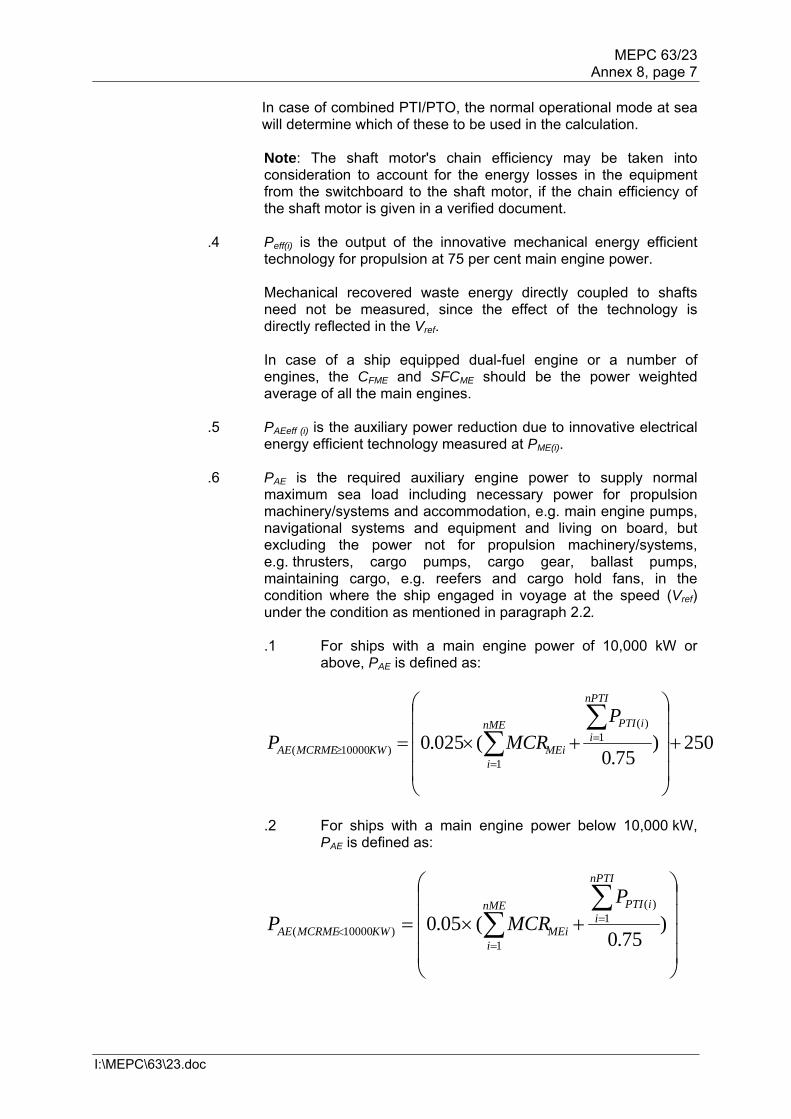
maximum sea load including necessary power for propulsion machinery/systems and accommodation, e.g. main engine pumps, navigational systems and equipment and living on board, but excluding the power not for propulsion machinery/systems, e.g. thrusters, cargo pumps, cargo gear, ballast pumps, maintaining cargo, e.g. reefers and cargo hold fans, in the condition where the ship engaged in voyage at the speed (Vref) under the condition as mentioned in paragraph 2.2. .1 For ships with a main engine power of 10,000 kW or
above, PAE is defined as:
250)75.0
(025.0 1)(
1)10000(
nPTI
iiPTInME
iMEiKWMCRMEAE
PMCRP
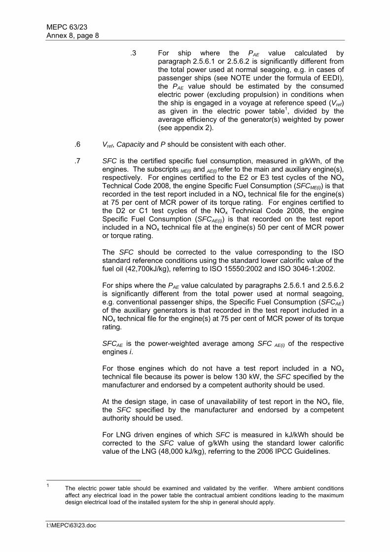
.2 For ships with a main engine power below 10,000 kW,
PAE is defined as:
)
75.0(05.0 1
)(
1)10000(
nPTI
iiPTInME
iMEiKWMCRMEAE
PMCRP
MEPC 63/23 Annex 8, page 8
I:\MEPC\63\23.doc
.3 For ship where the PAE value calculated by paragraph 2.5.6.1 or 2.5.6.2 is significantly different from the total power used at normal seagoing, e.g. in cases of passenger ships (see NOTE under the formula of EEDI), the PAE value should be estimated by the consumed electric power (excluding propulsion) in conditions when the ship is engaged in a voyage at reference speed (Vref) as given in the electric power table1, divided by the average efficiency of the generator(s) weighted by power (see appendix 2).
.6 Vref, Capacity and P should be consistent with each other. .7 SFC is the certified specific fuel consumption, measured in g/kWh, of the
engines. The subscripts ME(i) and AE(i) refer to the main and auxiliary engine(s), respectively. For engines certified to the E2 or E3 test cycles of the NOx Technical Code 2008, the engine Specific Fuel Consumption (SFCME(i)) is that recorded in the test report included in a NOx technical file for the engine(s) at 75 per cent of MCR power of its torque rating. For engines certified to the D2 or C1 test cycles of the NOx Technical Code 2008, the engine Specific Fuel Consumption (SFCAE(i)) is that recorded on the test report included in a NOx technical file at the engine(s) 50 per cent of MCR power or torque rating. The SFC should be corrected to the value corresponding to the ISO standard reference conditions using the standard lower calorific value of the fuel oil (42,700kJ/kg), referring to ISO 15550:2002 and ISO 3046-1:2002. For ships where the PAE value calculated by paragraphs 2.5.6.1 and 2.5.6.2 is significantly different from the total power used at normal seagoing, e.g. conventional passenger ships, the Specific Fuel Consumption (SFCAE) of the auxiliary generators is that recorded in the test report included in a NOx technical file for the engine(s) at 75 per cent of MCR power of its torque rating. SFCAE is the power-weighted average among SFC AE(i) of the respective engines i. For those engines which do not have a test report included in a NOx technical file because its power is below 130 kW, the SFC specified by the manufacturer and endorsed by a competent authority should be used. At the design stage, in case of unavailability of test report in the NOx file, the SFC specified by the manufacturer and endorsed by a competent authority should be used. For LNG driven engines of which SFC is measured in kJ/kWh should be corrected to the SFC value of g/kWh using the standard lower calorific value of the LNG (48,000 kJ/kg), referring to the 2006 IPCC Guidelines.
1 The electric power table should be examined and validated by the verifier. Where ambient conditions
affect any electrical load in the power table the contractual ambient conditions leading to the maximum design electrical load of the installed system for the ship in general should apply.

MEPC 63/23 Annex 8, page 9
I:\MEPC\63\23.doc
.8 fj is a correction factor to account for ship specific design elements:
.1 The power correction factor, fj, for ice-classed ships should be taken as the greater value of fj0 and fj,min as tabulated in Table 1 but not greater than fj,max = 1.0. For further information on approximate correspondence between ice classes, see HELCOM Recommendation 25/72.
Table 1: Correction factor for power f j for ice-classed ships
Ship type fj0
fj,min depending on the ice class
IA Super IA IB IC
Tanker
nME
iiME
PP
P
L
1)(
9201308.0 30015.0 PPL 21027.0 PPL 13045.0 PPL 06070.0 PPL
Bulk carrier
nME
iiME
PP
P
L
1)(
7541639.0 09047.0 PPL 07058.0 PPL 04073.0 PPL 02087.0 PPL
General cargo ship
nME
iiME
PP
P
L
1)(
48320227.0 16031.0 PPL 12043.0 PPL 09056.0 PPL 07067.0 PPL
.2 The factor fj, for shuttle tankers with propulsion redundancy should
be fj = 0.77. This correction factors applies to shuttle tankers with propulsion redundancy between 80,000 and 160,000 deadweight. The Shuttle Tankers with Propulsion Redundancy are tankers used for loading of crude oil from offshore installations equipped with dual-engine and twin-propellers need to meet the requirements for dynamic positioning and redundancy propulsion class notation.
.3 For other ship types, fj should be taken as 1.0.
.9 fw is a non-dimensional coefficient indicating the decrease of speed in representative sea conditions of wave height, wave frequency and wind speed (e.g. Beaufort Scale 6), and is determined as follows:
.1 for attained EEDI calculated under regulations 20 and 21 of
MARPOL Annex VI, fw is 1.00;
.2 when fw is calculated according to the subparagraph .2.1 or .2.2 below, the value for attained EEDI calculated by the formula in paragraph 2 using the obtained fw should be referred to as "attained EEDIweather";
.1 fw can be determined by conducting the ship specific
simulation on its performance at representative sea conditions. The simulation methodology should be based on the Guidelines developed by the Organization and the
2 HELCOM Recommendation 25/7 may be found at http://www.helcom.fi.

MEPC 63/23 Annex 8, page 10
I:\MEPC\63\23.doc
method and outcome for an individual ship should be verified by the Administration or an organization recognized by the Administration; and
.2 in cases where a simulation is not conducted, fw should be
taken from the "Standard fw " table/curve. A "Standard fw " table/curve is provided in the Guidelines3 for each ship type defined in paragraph 1, and expressed as a function of Capacity (e.g. deadweight). The "Standard fw " table/curve is based on data of actual speed reduction of as many existing ships as possible under the representative sea condition.
fw and attained EEDIweather, if calculated, with the representative sea conditions under which those values are determined, should be indicated in the EEDI Technical File to make a distinction with the attained EEDI calculated under regulations 20 and 21 of MARPOL Annex VI.
.10 feff(i) is the availability factor of each innovative energy efficiency technology.
feff(i) for waste energy recovery system should be one (1.0)4. .11 fi is the capacity factor for any technical/regulatory limitation on capacity,
and should be assumed to be one (1.0) if no necessity of the factor is granted.
.1 The capacity correction factor, fi, for ice-classed ships should be taken as the lesser value of fi0 and fi,max as tabulated in Table 2, but not less than fi,min = 1.0. For further information on approximate correspondence between ice classes, see HELCOM Recommendation 25/75. Table 2: Capacity correction factor fi for ice-classed ships
Ship type fi0
fi,max depending on the ice class
IA Super IA IB IC
Tanker capacity
LPP331300138.0 11010.2
PPL 08071.1 PPL 06047.1
PPL 04027.1 PPL
Bulk carrier capacity
LPP123300403.0 11010.2
PPL 09080.1 PPL 07054.1
PPL 05031.1 PPL
General cargo ship capacity
LPP625.20377.0 11018.2
PPL 08077.1 PPL 06051.1
PPL 04028.1 PPL
Containership capacity
LPP329.21033.0 11010.2
PPL 08071.1 PPL 06047.1
PPL 04027.1 PPL
Gas carrier capacity
LPP590.20474.0 25.1 12010.2
PPL 08060.1 PPL 04025.1
PPL
Note: containership capacity is defined as 70% of the DWT.
3 Guidelines for the calculation of the coefficient fw for the decrease of ship speed in respective sea
conditions will be developed. 4 EEDI calculation should be based on the normal sea-going condition outside Emission Control Area
designated under paragraph 6 of regulation 13 in MARPOL ANNEX VI. 5 HELCOM Recommendation 25/7 may be found at http://www.helcom.fi.
MEPC 63/23 Annex 8, page 11
I:\MEPC\63\23.doc
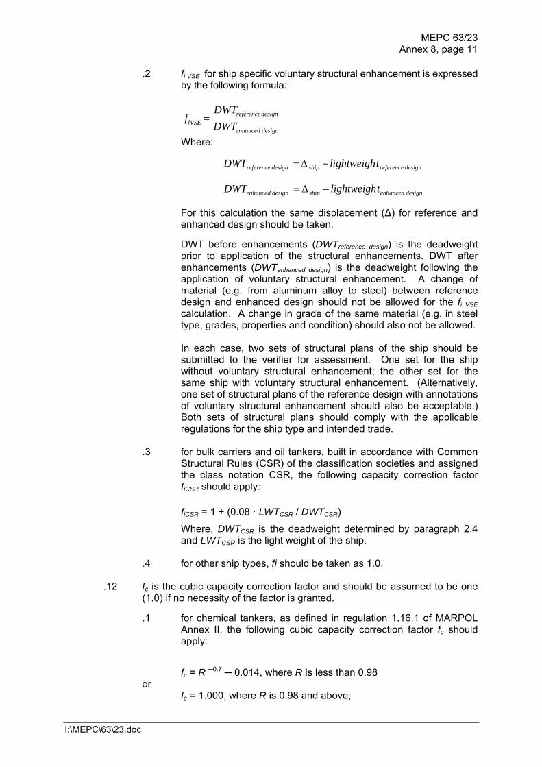
.2 fi VSE for ship specific voluntary structural enhancement is expressed by the following formula:
designenhanced
designreferenceVSEi DWT
DWTf
Where:
designreferenceshipdesignreference tlightweighDWT
designenhancedshipdesignenhanced tlightweighDWT
For this calculation the same displacement (∆) for reference and enhanced design should be taken.
DWT before enhancements (DWTreference design) is the deadweight prior to application of the structural enhancements. DWT after enhancements (DWTenhanced design) is the deadweight following the application of voluntary structural enhancement. A change of material (e.g. from aluminum alloy to steel) between reference design and enhanced design should not be allowed for the fi VSE calculation. A change in grade of the same material (e.g. in steel type, grades, properties and condition) should also not be allowed. In each case, two sets of structural plans of the ship should be submitted to the verifier for assessment. One set for the ship without voluntary structural enhancement; the other set for the same ship with voluntary structural enhancement. (Alternatively, one set of structural plans of the reference design with annotations of voluntary structural enhancement should also be acceptable.) Both sets of structural plans should comply with the applicable regulations for the ship type and intended trade.
.3 for bulk carriers and oil tankers, built in accordance with Common Structural Rules (CSR) of the classification societies and assigned the class notation CSR, the following capacity correction factor fiCSR should apply:
fiCSR = 1 + (0.08 · LWTCSR / DWTCSR)
Where, DWTCSR is the deadweight determined by paragraph 2.4 and LWTCSR is the light weight of the ship.
.4 for other ship types, fi should be taken as 1.0.
.12 fc is the cubic capacity correction factor and should be assumed to be one
(1.0) if no necessity of the factor is granted.
.1 for chemical tankers, as defined in regulation 1.16.1 of MARPOL Annex II, the following cubic capacity correction factor fc should apply:
fc = R ─0.7 ─ 0.014, where R is less than 0.98 or
fc = 1.000, where R is 0.98 and above;
MEPC 63/23 Annex 8, page 12
I:\MEPC\63\23.doc
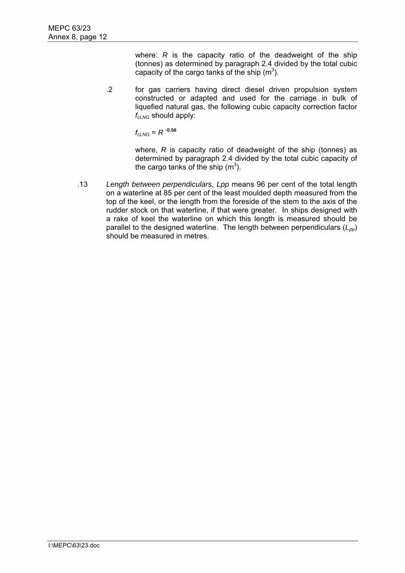
where: R is the capacity ratio of the deadweight of the ship (tonnes) as determined by paragraph 2.4 divided by the total cubic capacity of the cargo tanks of the ship (m3).
.2 for gas carriers having direct diesel driven propulsion system
constructed or adapted and used for the carriage in bulk of liquefied natural gas, the following cubic capacity correction factor fcLNG should apply:
fcLNG = R -0.56
where, R is capacity ratio of deadweight of the ship (tonnes) as determined by paragraph 2.4 divided by the total cubic capacity of the cargo tanks of the ship (m3).
.13 Length between perpendiculars, Lpp means 96 per cent of the total length
on a waterline at 85 per cent of the least moulded depth measured from the top of the keel, or the length from the foreside of the stem to the axis of the rudder stock on that waterline, if that were greater. In ships designed with a rake of keel the waterline on which this length is measured should be parallel to the designed waterline. The length between perpendiculars (Lpp) should be measured in metres.


MEPC 63/23 Annex 8, page 14
I:\MEPC\63\23.doc
APPENDIX 2
GUIDELINES FOR THE DEVELOPMENT OF ELECTRIC POWER TABLES FOR EEDI (EPT-EEDI)
1 Introduction to the document "Electric Power Table for EEDI" 1.1 This appendix contains a guideline for the document "Electric Power Table for EEDI" which is similar to the actual shipyards' load balance document, utilizing well defined criteria, providing standard format, clear loads definition and grouping, standard load factors, etc. A number of new definitions (in particular the "groups") are introduced, giving an apparent greater complexity to the calculation process. However, this intermediate step to the final calculation of PAE stimulates all the parties to a deep investigation through the global figure of the auxiliary load, allowing comparisons between different ships and technologies and eventually identifying potential efficiencies improvements. 2 Auxiliary load power definition 2.2 PAE is to be calculated as indicated in paragraph 2.5.6 of the Guidelines, together with the following additional three conditions:
.1 no emergency situations (e.g. "no fire", "no flood", "no blackout", "no partial
blackout"); .2 evaluation time frame of 24 hours (to account loads with intermittent use);
and .3 ship fully loaded of passenger and/or cargo and crew.
3 Definition of the data to be included in the Electric Power Table for EEDI 3.1 The Electric power table for EEDI calculation should contain the following data elements, as appropriate:
.1 Load's group; .2 Load's description; .3 Load's identification tag; .4 Load's electric circuit Identification; .5 Load's mechanical rated power "Pm" [kW]; .6 Load's electric motor rated output power [kW]; .7 Load's electric motor efficiency "e" [/]; .8 Load's Rated electric power "Pr" [kW]; .9 Service factor of load "kl" [/]; .10 Service factor of duty "kd" [/]; .11 Service factor of time "kt" [/]; .12 Service total factor of use "ku" [/], where ku=kl·kd·kt; .13 Load's necessary power "Pload" [kW], where Pload=Pr·ku; .14 Notes; .15 Group's necessary power [kW]; and .16 Auxiliaries load's power PAE [kW].

MEPC 63/23 Annex 8, page 15
I:\MEPC\63\23.doc
4 Data to be included in the Electric Power Table for EEDI Load groups 4.1 The Loads are put into defined groups, allowing a proper breakdown of the auxiliaries. This eases the verification process and makes it possible to identify those areas where load reductions might be possible. The groups are listed below:
.1 A Hull, Deck, Navigation and Safety services; .2 B Propulsion service auxiliaries; .3 C Auxiliary Engine and Main Engine Services; .4 D Ship's General services; .5 E Ventilation for Engine-rooms and Auxiliaries room; .6 F Air Conditioning services; .7 G Galleys, refrigeration and Laundries services; .8 H Accommodation services; .9 I Lighting and socket services; .10 L Entertainment services; .11 N Cargo loads; and .12 M Miscellaneous.
All the ship's loads have to be delineated in the document, excluding only PAeff, the shaft motors and shaft motors chain (while the propulsion services auxiliaries are partially included below in paragraph 4.1.2 B). Some loads (i.e. thrusters, cargo pumps, cargo gear, ballast pumps, maintaining cargo, reefers and cargo hold fans) still are included in the group for sake of transparency, however their service factor is zero in order to comply with rows 4 and 5 of paragraph 2.5.6 of the Guidelines, therefore making it easier to verify that all the loads have been considered in the document and there are no loads left out of the measurement. 4.1.1 A Hull, Deck, Navigation and safety services
.1 loads included in the Hull services typically are: ICCP systems, mooring equipment, various doors, ballasting systems, Bilge systems, Stabilizing equipment, etc. Ballasting systems are indicated with service factor equal to zero to comply with row 5 of paragraph 2.5.6 of the Guidelines;
.2 loads included in the deck services typically are: deck and balcony washing
systems, rescue systems, cranes, etc.; .3 loads included in the navigation services typically are: navigation systems,
navigation's external and internal communication systems, steering systems, etc.; and
.4 loads included in the safety services typically are: active and passive fire
systems, emergency shutdown systems, public address systems, etc. 4.1.2 B Propulsion service auxiliaries This group typically includes: propulsion secondary cooling systems such as LT cooling pumps dedicated to shaft motors, LT cooling pumps dedicated to propulsion converters, propulsion UPSs, etc. Propulsion service Loads do not include shaft motors (PTI(i)) and the auxiliaries which are part of them (shaft motor own cooling fans and pump, etc.) and the shaft motor chain losses and auxiliaries which are part of them (i.e. shaft motor converters including relevant auxiliaries such as converter own cooling fans and pumps, shaft motor

MEPC 63/23 Annex 8, page 16
I:\MEPC\63\23.doc
transformers including relevant auxiliaries losses such as propulsion transformer own cooling fans and pumps, shaft motor Harmonic filter including relevant auxiliaries losses, shaft motor excitation system including the relevant auxiliaries consumed power, etc.). Propulsion service auxiliaries include manoeuvring propulsion equipments such as manoeuvring thrusters and their auxiliaries whose service factor is to be set to zero. 4.1.3 C – Auxiliary Engine and Main Engine Services This group includes: cooling systems, i.e. pumps and fans for cooling circuits dedicated to alternators or propulsion shaft engines (seawater, technical water dedicated pumps, etc.), lubricating and fuel systems feeding, transfer, treatment and storage, ventilation system for combustion air supply, etc. 4.1.4 D – Ship's General services This group includes Loads which provide general services which can be shared between shaft motor, auxiliary engines and main engine and accommodation support systems. Loads typically included in this group are: Cooling systems, i.e. pumping seawater, technical water main circuits, compressed air systems, fresh water generators, automation systems, etc. 4.1.5 E Ventilation for Engine-rooms and Auxiliaries room This group includes all fans providing ventilation for engine-rooms and auxiliary rooms that typically are: Engine-rooms cooling supply-exhaust fans, auxiliary rooms supply and exhaust fans. All the fans serving accommodation areas or supplying combustion air are not included in this group. This group does not include cargo hold fans, and garage supply and exhaust fans. 4.1.6 F Air Conditioning services All Loads that make up the air conditioning service that typically are: air conditioning chillers, air conditioning cooling and heating fluids transfer and treatment, air conditioning's air handling units ventilation, air conditioning re-heating systems with associated pumping, etc. The air conditioning chillers service factor of load, service factor of time and service factor of duty are to be set as 1 (kl=1, kt=1 and kd=1) in order to avoid the detailed validation of the heat load dissipation document (i.e. the chiller's electric motor rated power is to be used). However, kd is to represent the use of spare chillers (e.g. four chillers are installed and one out four is spare then kd=0 for the spare chiller and kd=1 for the remaining three chillers), but only when the number of spare chillers is clearly demonstrated via the heat load dissipation document. 4.1.7 G Galleys, refrigeration and Laundries services All Loads related to the galleys, pantries refrigeration and laundry services that typically are: Galleys various machines, cooking appliances, galleys' cleaning machines, galleys auxiliaries, refrigerated room systems including refrigeration compressors with auxiliaries, air coolers, etc. 4.1.8 H Accommodation services All Loads related to the accommodation services of passengers and crew that typically are: crew and passengers' transportation systems, i.e. lifts, escalators, etc., environmental services, i.e. black and grey water collecting, transfer, treatment, storage, discharge, waste systems including collecting, transfer, treatment, storage, etc., accommodation fluids transfers, i.e. sanitary hot and cold water pumping, etc., treatment units, pools systems, saunas, gym equipments, etc.
MEPC 63/23 Annex 8, page 17
I:\MEPC\63\23.doc
4.1.9 I Lighting and socket services All Loads related to the lighting, entertainment and socket services. As the quantity of lighting circuits and sockets within the ship may be significantly high, it is not practically feasible to list all the lighting circuits and points in the EPT for EEDI. Therefore circuits should be grouped into subgroups aimed to identify possible improvements of efficient use of power. The subgroups are:
.1 Lighting for 1) cabins, 2) corridors, 3) technical rooms/stairs, 4) public spaces/stairs, 5) engine-rooms and auxiliaries' room, 6) external areas, 7) garages and 8) cargo spaces. All have to be divided by main vertical zone; and
.2 Power sockets for 1) cabins, 2) corridors, 3) technical rooms/stairs,
4) public spaces/stairs, 5) engine-rooms and auxiliaries' room, 6) garages and 7) cargo spaces. All have to be divided by main vertical zone.
The calculation criteria for complex groups (e.g. cabin lighting and power sockets) subgroups are to be included via an explanatory note, indicating the load composition (e.g. lights of typical cabins, TV, hair dryer, fridge, etc., typical cabins). 4.1.10 L – Entertainment services This group includes all Loads related to the entertainment services that typically are: public spaces audio and video equipments, theatre stage equipments, IT systems for offices, video games, etc. 4.1.11 N – Cargo Loads This group will contain all cargo loads such as cargo pumps, cargo gear, maintaining cargo, cargo reefers loads, cargo hold fans and garage fans for sake of transparency. However, the service factor of this group is to be set to zero. 4.1.12 M – Miscellaneous This group will contain all loads which have not been associated to the above-mentioned groups but still are contributing to the overall load calculation of the normal maximum sea load. Loads description 4.2 This identifies the loads (for example "seawater pump"). Loads identification tag 4.3 This tag identifies the loads according to the shipyard's standards tagging system. For example, the "PTI1 fresh water pump" identification tag is "SYYIA/C" for an example ship and shipyard. This data provides a unique identifier for each load. Loads electric circuit Identification 4.4 This is the tag of the electric circuit supplying the load. Such information allows the data validation process.

MEPC 63/23 Annex 8, page 18
I:\MEPC\63\23.doc
Loads mechanical rated power "Pm" 4.5 This data is to be indicated in the document only when th electric load is made by an electric motor driving a mechanical load (for example a fan, a pump, etc.). This is the rated power of the mechanical device driven by an electric motor. Loads electric motor rated output power [kW] 4.6 The output power of the electric motor as per maker's name plate or technical specification. This data does not take part of the calculation but is useful to highlight potential over rating of the combination motor-mechanical load. Loads electric motor efficiency "e" [/] 4.7 This data is to be entered in the document only when the electric load is made by an electric motor driving a mechanical load. Loads rated electric power "Pr" [kW] 4.8 Typically the maximum electric power absorbed at the load electric terminals at which the load has been designed for its service, as indicated on the maker's name plate and/or maker's technical specification. When the electric load is made by an electric motor driving a mechanical load the load's rated electric power is: Pr=Pm/e [kW]. Service factor of load "kl" [/] 4.9 Provides the reduction from the loads rated electric power to loads necessary electric power that is to be made when the load absorb less power than its rated power. For example, in case of electric motor driving a mechanical load, a fan could be designed with some power margin, leading to the fact that the fan rated mechanical power exceeds the power requested by the duct system it serves. Another example is when a pump rated power exceed the power needed for pumping in its delivery fluid circuit. Another example in case of electric self-regulating semi-conductors electric heating system is oversized and the rated power exceeds the power absorbed, according a factor kl. Service factor of duty "kd" [/] 4.10 Factor of duty is to be used when a function is provided by more than one load. As all loads have to be included in the EPT for EEDI, this factor provides a correct summation of the loads. For example when two pumps serve the same circuit and they run in duty/stand-by their Kd factor will be ½ and ½. When three compressors serves the same circuit and one runs in duty and two in stand-by, then kd is 1/3, 1/3 and 1/3. Service factor of time "kt" [/] 4.11 A factor of time based on the shipyard's evaluation about the load duty along 24 hours of ship's navigation as defined at paragraph 3. For example the Entertainment loads operate at their power for a limited period of time, 4 hours out 24 hours; as a consequence kt=4/24. For example, the seawater cooling pumps operate at their power all the time during the navigation at Vref. As a consequence kt=1.

MEPC 63/23 Annex 8, page 19
I:\MEPC\63\23.doc
Service total factor of use "ku" [/] 4.12 The total factor of use that takes into consideration all the service factors: ku=kl·kd·kt. Loads necessary power "Pload" [kW] 4.13 The individual user contribution to the auxiliary load power is Pload=Pr·ku. Notes 4.14 A note, as free text, could be included in the document to provide explanations to the verifier. Groups necessary power [kW] 4.15 The summation of the "Loads necessary power" from group A to N. This is an intermediate step which is not strictly necessary for the calculation of PAE. However, it is useful to allow a quantitative analysis of the PAE, providing a standard breakdown for analysis and potential improvements of energy saving. Auxiliaries load's power PAE [kW] 4.16 Auxiliaries load's power PAE is the summation of the "Load's necessary power" of all the loads divided by the average efficiency of the generator(s) weighted by power.
PAE=ΣPload(i)/( average efficiency of the generator(s) weighted by power) Layout and organization of the data indicated in the "Electric power table for EEDI" 5 The document "Electric power table for EEDI" is to include general information (i.e. ship's name, project name, document references, etc.) and a table with:
.1 one row containing column titles; .2 one Column for table row ID; .3 one Column for the groups identification ("A", "B", etc.) as indicated in
paragraphs 4.1.1 to 4.1.12 of this guideline; .4 one Column for the group descriptions as indicated in paragraphs 4.1.1
to 4.1.12 of this guideline; .5 one column each for items in paragraphs 4.2 to 4.14 of this guideline
(e.g. "load tag", etc.); .6 one row dedicated to each individual load; .7 the summation results (i.e. summation of powers) including data from
paragraphs 4.15 to 4.16 of this guideline; and .8 explanatory notes.
An example of an Electric Power Table for EEDI for a cruise postal vessel which transports passenger and have a car garage and reefer holds for fish trade transportation is indicated below. The data indicated and the type of ship is for reference only.

MEPC 63/23 Annex 8, page 20
I:\MEPC\63\23.doc
***
MEPC 63/23/Add.1 Annex 10, page 1
I:\MEPC\63\23-Add-1.doc
ANNEX 10
RESOLUTION MEPC.214(63) Adopted on 2 March 2012
2012 GUIDELINES ON SURVEY AND CERTIFICATION OF THE
ENERGY EFFICIENCY DESIGN INDEX (EEDI) THE MARINE ENVIRONMENT PROTECTION COMMITTEE, RECALLING Article 38(a) of the Convention on the International Maritime Organization concerning the functions of the Marine Environment Protection Committee (the Committee) conferred upon it by international conventions for the prevention and control of marine pollution, RECALLING ALSO that, at its sixty-second session, the Committee adopted, by resolution MEPC.203(62), amendments to the Annex of the Protocol of 1997 to amend the International Convention for the Prevention of Pollution from Ships, 1973, as modified by the Protocol of 1978 relating thereto (inclusion of regulations on energy efficiency for ships in MARPOL Annex VI), NOTING the amendments to MARPOL Annex VI adopted at its sixty-second session by inclusion of a new chapter 4 for regulations on energy efficiency for ships, are expected to enter into force on 1 January 2013 upon their acceptance on 1 July 2012, NOTING ALSO that regulation 5 (Surveys) of MARPOL Annex VI, as amended, requires ships to which chapter 4 applies shall also be subject to survey and certification taking into account guidelines developed by the Organization, RECOGNIZING that the amendments to MARPOL Annex VI requires the adoption of relevant guidelines for smooth and uniform implementation of the regulations and to provide sufficient lead time for industry to prepare, HAVING CONSIDERED, at its sixty-third session, the draft 2012 Guidelines on survey and certification of the Energy Efficiency Design Index (EEDI), 1. ADOPTS the 2012 Guidelines on survey and certification of the Energy Efficiency Design Index (EEDI), as set out in the annex to the present resolution; 2. INVITES Administrations to take the annexed Guidelines into account when developing and enacting national laws which give force to and implement provisions set forth in regulation 5 of MARPOL Annex VI, as amended; 3. REQUESTS the Parties to MARPOL Annex VI and other Member Governments to bring the annexed Guidelines on survey and certification of the Energy Efficiency Design Index (EEDI), to the attention of masters, seafarers, shipowners, ship operators and any other interested groups; 4. AGREES to keep these Guidelines under review in light of the experience gained; and 5. REVOKES Interim Guidelines circulated by MEPC.1/Circ.682, as from this date.

MEPC 63/23/Add.1 Annex 10, page 2
I:\MEPC\63\23-Add-1.doc
ANNEX
2012 GUIDELINES ON SURVEY AND CERTIFICATION OF THE ENERGY EFFICIENCY DESIGN INDEX (EEDI)
TABLE OF CONTENTS 1 GENERAL 2 DEFINITIONS 3 APPLICATION 4 PROCEDURES FOR SURVEY AND CERTIFICATION
4.1 General 4.2 Preliminary verification of the attained EEDI at the design stage 4.3 Final verification of the attained EEDI at sea trial 4.4 Verification of the attained EEDI in case of major conversion
Appendix 1 Sample of EEDI Technical File Appendix 2 Guidelines for validation of electric power tables for EEDI (EPT-EEDI) Appendix 3 Electric power table form for EEDI (EPT-EEDI Form) and statement of
validation

MEPC 63/23/Add.1 Annex 10, page 3
I:\MEPC\63\23-Add-1.doc
1 GENERAL The purpose of these Guidelines is to assist verifiers of Energy Efficiency Design Index (EEDI) of ships in conducting the survey and certification of the EEDI in accordance with regulations 5, 6, 7, 8 and 9 of MARPOL Annex VI, and assist shipowners, shipbuilders and manufacturers being related to the energy efficiency of a ship and other interested parties in understanding the procedures of the survey and certification of the EEDI. 2 DEFINITIONS1 2.1 Verifier means an Administration or organization duly authorized by it, which conducts the survey and certification of the EEDI in accordance with regulations 5, 6, 7, 8 and 9 of MARPOL Annex VI and these Guidelines. 2.2 Ship of the same type means a ship of which hull form (expressed in the lines such as sheer plan and body plan) excluding additional hull features such as fins and of which principal particulars are identical to that of the base ship. 2.3 Tank test means model towing tests, model self-propulsion tests and model propeller open water tests. Numerical calculations may be accepted as equivalent to model propeller open water tests or used to complement the tank tests conducted (e.g. to evaluate the effect of additional hull features such as fins, etc., on ship's performance), with approval of the verifier. 3 APPLICATION These Guidelines should be applied to new ships for which an application for an initial survey or an additional survey specified in regulation 5 of MARPOL Annex VI has been submitted to a verifier. 4 PROCEDURES FOR SURVEY AND CERTIFICATION 4.1 General 4.1.1 Attained EEDI should be calculated in accordance with regulation 20 of MARPOL Annex VI and the "Guidelines on the method of calculation of the attained EEDI for new ships" ("EEDI Calculation Guidelines", hereafter). Survey and certification of the EEDI should be conducted on two stages: preliminary verification at the design stage, and final verification at the sea trial. The basic flow of the survey and certification process is presented in figure 1. 4.1.2 The information used in the verification process may contain confidential information of submitters, which requires Intellectual Property Rights (IPR) protection. In the case where the submitter want a non-disclosure agreement with the verifier, the additional information should be provided to the verifier upon mutually agreed terms and conditions.
1 Other terms used in these Guidelines have the same meaning as those defined in the EEDI Calculation
Guidelines.
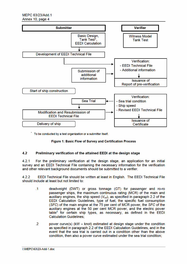
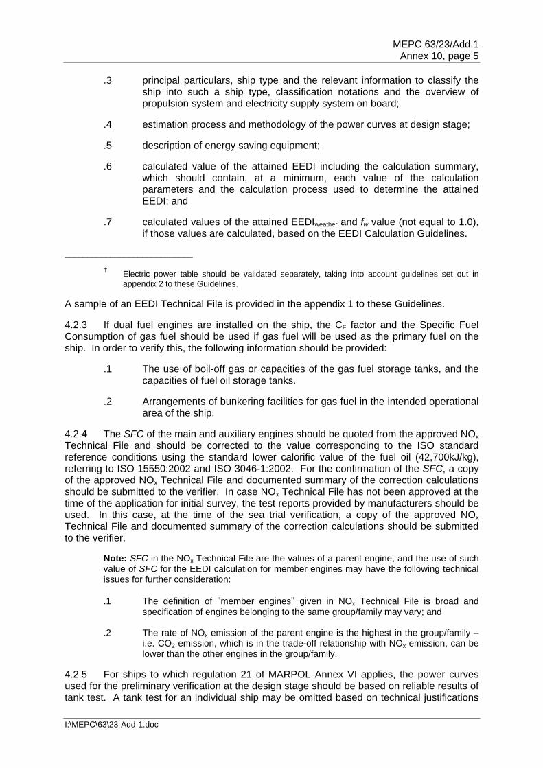
MEPC 63/23/Add.1 Annex 10, page 5
I:\MEPC\63\23-Add-1.doc
.3 principal particulars, ship type and the relevant information to classify the ship into such a ship type, classification notations and the overview of propulsion system and electricity supply system on board;
.4 estimation process and methodology of the power curves at design stage; .5 description of energy saving equipment; .6 calculated value of the attained EEDI including the calculation summary,
which should contain, at a minimum, each value of the calculation parameters and the calculation process used to determine the attained EEDI; and
.7 calculated values of the attained EEDIweather and fw value (not equal to 1.0),
if those values are calculated, based on the EEDI Calculation Guidelines. ____________________________
† Electric power table should be validated separately, taking into account guidelines set out in appendix 2 to these Guidelines.
A sample of an EEDI Technical File is provided in the appendix 1 to these Guidelines. 4.2.3 If dual fuel engines are installed on the ship, the CF factor and the Specific Fuel Consumption of gas fuel should be used if gas fuel will be used as the primary fuel on the ship. In order to verify this, the following information should be provided:
.1 The use of boil-off gas or capacities of the gas fuel storage tanks, and the capacities of fuel oil storage tanks.
.2 Arrangements of bunkering facilities for gas fuel in the intended operational
area of the ship. 4.2.4 The SFC of the main and auxiliary engines should be quoted from the approved NOx Technical File and should be corrected to the value corresponding to the ISO standard reference conditions using the standard lower calorific value of the fuel oil (42,700kJ/kg), referring to ISO 15550:2002 and ISO 3046-1:2002. For the confirmation of the SFC, a copy of the approved NOx Technical File and documented summary of the correction calculations should be submitted to the verifier. In case NOx Technical File has not been approved at the time of the application for initial survey, the test reports provided by manufacturers should be used. In this case, at the time of the sea trial verification, a copy of the approved NOx Technical File and documented summary of the correction calculations should be submitted to the verifier.
Note: SFC in the NOx Technical File are the values of a parent engine, and the use of such value of SFC for the EEDI calculation for member engines may have the following technical issues for further consideration:
.1 The definition of "member engines" given in NOx Technical File is broad and
specification of engines belonging to the same group/family may vary; and .2 The rate of NOx emission of the parent engine is the highest in the group/family –
i.e. CO2 emission, which is in the trade-off relationship with NOx emission, can be lower than the other engines in the group/family.
4.2.5 For ships to which regulation 21 of MARPOL Annex VI applies, the power curves used for the preliminary verification at the design stage should be based on reliable results of tank test. A tank test for an individual ship may be omitted based on technical justifications

MEPC 63/23/Add.1 Annex 10, page 6
I:\MEPC\63\23-Add-1.doc
such as availability of the results of tank tests for ships of the same type. In addition, omission of tank tests is acceptable for a ship for which sea trials will be carried under the condition as specified in paragraph 2.2 of the EEDI Calculation Guidelines, upon agreement of the shipowner and shipbuilder and with approval of the verifier. For ensuring the quality of tank tests, ITTC quality system should be taken into account. Model tank test should be witnessed by the verifier.
Note: It would be desirable in the future that an organization conducting a tank test be authorized.
4.2.6 The verifier may request the submitter for additional information on top of those contained in Technical File, as necessary, to examine the calculation process of the attained EEDI. The estimation of the ship speed at the design stage much depends on each shipbuilder's experiences, and it may not be practicable for any person/organization other than the shipbuilder to fully examine the technical aspects of experience-based parameters such as the roughness coefficient and wake scaling coefficient. Therefore, the preliminary verification should focus on the calculation process of the attained EEDI to ensure that it is technically sound and reasonable and follows regulation 20 of MARPOL Annex VI and the EEDI Calculation Guidelines.
Note 1: A possible way forward for more robust verification is to establish a standard methodology of deriving the ship speed from the outcomes of tank test, by setting standard values for experience-based correction factors such as roughness coefficient and wake scaling coefficient. In this way, ship-by-ship performance comparison could be made more objectively by excluding the possibility of arbitrary setting of experience-based parameters. If such standardization is sought, this would have an implication on how the ship speed adjustment based on sea trial results should be conducted in accordance with paragraph 4.3.8 of these Guidelines. Note 2: A joint industry standard to support the method and role of the verifier will be developed.
4.2.7 Additional information that the verifier may request the submitter to provide directly to it includes but not limited to:
.1 descriptions of a tank test facility; this should include the name of the
facility, the particulars of tanks and towing equipment, and the records of calibration of each monitoring equipment;
.2 lines of a model ship and an actual ship for the verification of the
appropriateness of the tank test; the lines (sheer plan, body plan and half-breadth plan) should be detailed enough to demonstrate the similarity between the model ship and the actual ship;
.3 lightweight of the ship and displacement table for the verification of the
deadweight; .4 detailed report on the method and results of the tank test; this should
include at least the tank test results at sea trial condition and under the condition as specified in paragraph 2.2 of the EEDI Calculation Guidelines;
.5 detailed calculation process of the ship speed, which should include the
estimation basis of experience-based parameters such as roughness coefficient, wake scaling coefficient; and
.6 reasons for exempting a tank test, if applicable; this should include lines
and tank test results of the ships of same type, and the comparison of the

MEPC 63/23/Add.1 Annex 10, page 7
I:\MEPC\63\23-Add-1.doc
principal particulars of such ships and the ship in question. Appropriate technical justification should be provided explaining why the tank test is unnecessary.
4.2.8 The verifier should issue the report on the "Preliminary Verification of EEDI" after it has verified the attained EEDI at the design stage in accordance with paragraphs 4.1 and 4.2 of these Guidelines. 4.3 Final verification of the attained EEDI at sea trial 4.3.1 Sea trial conditions should be set as conditions specified in paragraph 2.2 of the EEDI Calculation Guidelines, if possible. 4.3.2 Prior to the sea trial, the following documents should be submitted to the verifier: a description of the test procedure to be used for the speed trial, the final displacement table and the measured lightweight, or a copy of the survey report of deadweight, as well as a copy of NOx Technical File as necessary. The test procedure should include, at a minimum, descriptions of all necessary items to be measured and corresponding measurement methods to be used for developing power curves under the sea trial condition. 4.3.3 The verifier should attend the sea trial and confirm:
.1 propulsion and power supply system, particulars of the engines, and other relevant items described in the EEDI Technical File;
.2 draught and trim; .3 sea conditions; .4 ship speed; and .5 shaft power and RPM of the main engine.
4.3.4 Draught and trim should be confirmed by the draught measurements taken prior to the sea trial. The draught and trim should be as close as practical to those at the assumed conditions used for estimating the power curves. 4.3.5 Sea conditions should be measured in accordance with ISO 15016:2002 or the equivalent. 4.3.6 Ship speed should be measured in accordance with ISO 15016:2002 or the equivalent and at more than two points of which range includes the power of the main engine as specified in paragraph 2.5 of the EEDI Calculation Guidelines. 4.3.7 The main engine output should be measured by shaft power meter or a method which the engine manufacturer recommends and the verifier approves. Other methods may be acceptable upon agreement of the shipowner and shipbuilder and with approval of the verifier. 4.3.8 The submitter should develop power curves based on the measured ship speed and the measured output of the main engine at sea trial. For the development of the power curves, the submitter should calibrate the measured ship speed, if necessary, by taking into account the effects of wind, tide, waves, shallow water and displacement in accordance with
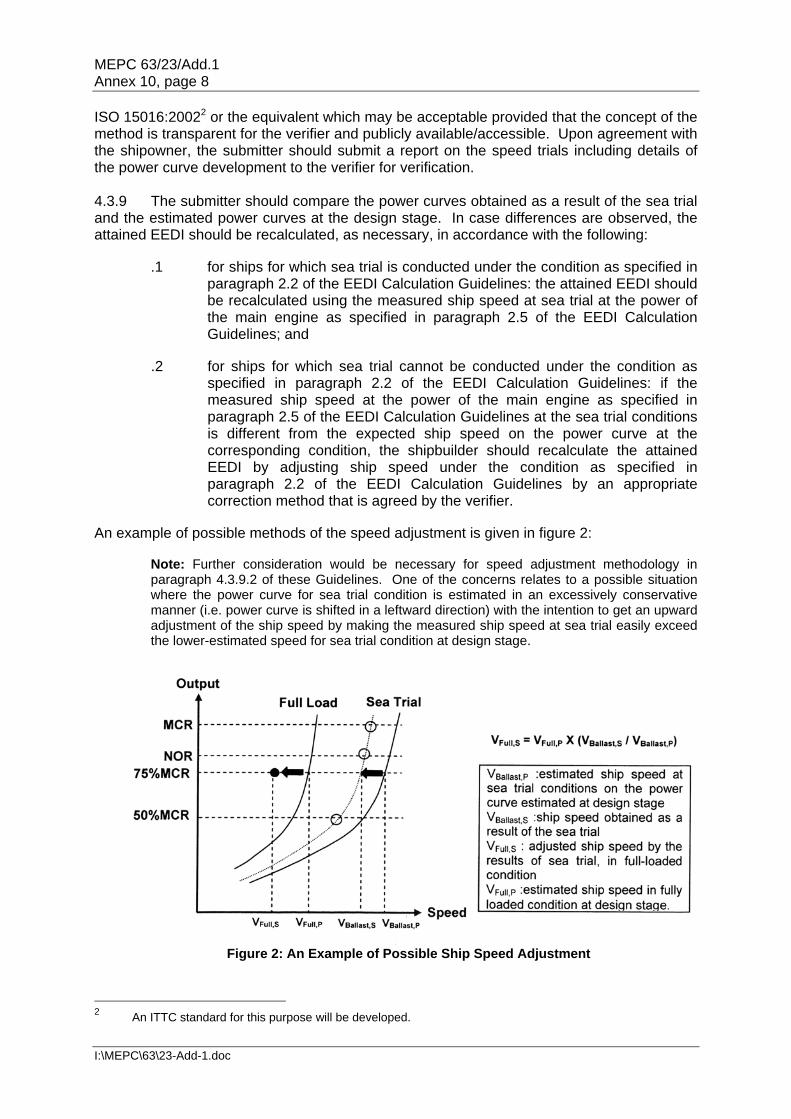
MEPC 63/23/Add.1 Annex 10, page 8
I:\MEPC\63\23-Add-1.doc
ISO 15016:20022 or the equivalent which may be acceptable provided that the concept of the method is transparent for the verifier and publicly available/accessible. Upon agreement with the shipowner, the submitter should submit a report on the speed trials including details of the power curve development to the verifier for verification. 4.3.9 The submitter should compare the power curves obtained as a result of the sea trial and the estimated power curves at the design stage. In case differences are observed, the attained EEDI should be recalculated, as necessary, in accordance with the following:
.1 for ships for which sea trial is conducted under the condition as specified in
paragraph 2.2 of the EEDI Calculation Guidelines: the attained EEDI should be recalculated using the measured ship speed at sea trial at the power of the main engine as specified in paragraph 2.5 of the EEDI Calculation Guidelines; and
.2 for ships for which sea trial cannot be conducted under the condition as
specified in paragraph 2.2 of the EEDI Calculation Guidelines: if the measured ship speed at the power of the main engine as specified in paragraph 2.5 of the EEDI Calculation Guidelines at the sea trial conditions is different from the expected ship speed on the power curve at the corresponding condition, the shipbuilder should recalculate the attained EEDI by adjusting ship speed under the condition as specified in paragraph 2.2 of the EEDI Calculation Guidelines by an appropriate correction method that is agreed by the verifier.
An example of possible methods of the speed adjustment is given in figure 2:
Note: Further consideration would be necessary for speed adjustment methodology in paragraph 4.3.9.2 of these Guidelines. One of the concerns relates to a possible situation where the power curve for sea trial condition is estimated in an excessively conservative manner (i.e. power curve is shifted in a leftward direction) with the intention to get an upward adjustment of the ship speed by making the measured ship speed at sea trial easily exceed the lower-estimated speed for sea trial condition at design stage.
Figure 2: An Example of Possible Ship Speed Adjustment
2 An ITTC standard for this purpose will be developed.

MEPC 63/23/Add.1 Annex 10, page 9
I:\MEPC\63\23-Add-1.doc
4.3.10 In cases where the finally determined deadweight/gross tonnage differs from the designed deadweight/gross tonnage used in the EEDI calculation during the preliminary verification, the submitter should recalculate the attained EEDI using the finally determined deadweight/gross tonnage. The finally determined gross tonnage should be confirmed in the Tonnage Certificate of the ship. 4.3.11 In case where the attained EEDI is calculated at the preliminary verification by using SFC based on the manufacturer's test report due to the non-availability at that time of the approved NOx Technical File, the EEDI should be recalculated by using SFC in the approved NOx Technical File. 4.3.12 The EEDI Technical File should be revised, as necessary, by taking into account the results of sea trial. Such revision should include, as applicable, the adjusted power curve based on the results of sea trial (namely, modified ship speed under the condition as specified in paragraph 2.2 of the EEDI Calculation Guidelines), the finally determined deadweight/gross tonnage and SFC described in the approved NOx Technical File, and the recalculated attained EEDI based on these modifications. 4.3.13 The EEDI Technical File, if revised, should be submitted to the verifier for the confirmation that the (revised) attained EEDI is calculated in accordance with regulation 20 of MARPOL Annex VI and the EEDI Calculation Guidelines. 4.4 Verification of the attained EEDI in case of major conversion 4.4.1 In cases where a major conversion is made to a ship, the shipowner should submit to a verifier an application for an Additional Survey with the EEDI Technical File duly revised based on the conversion made and other relevant background documents. 4.4.2 The background documents should include at least but are not limited to:
.1 documents explaining details of the conversion; .2 EEDI parameters changed after the conversion and the technical
justifications for each respective parameter; .3 reasons for other changes made in the EEDI Technical File, if any; and .4 calculated value of the attained EEDI with the calculation summary, which
should contain, at a minimum, each value of the calculation parameters and the calculation process used to determine the attained EEDI after the conversion.
4.4.3 The verifier should review the revised EEDI Technical File and other documents submitted and verify the calculation process of the attained EEDI to ensure that it is technically sound and reasonable and follows regulation 20 of MARPOL Annex VI and the EEDI Calculation Guidelines. 4.4.4 For verification of the attained EEDI after a conversion, speed trials of the ship are required, as necessary.

MEPC 63/23/Add.1 Annex 10, page 10
I:\MEPC\63\23-Add-1.doc
APPENDIX 1
SAMPLE OF EEDI TECHNICAL FILE 1 Data 1.1 General information Shipbuilder JAPAN Shipbuilding Company Hull No. 12345 IMO No. 94111XX Kind of ship Bulk carrier
1.2 Principal particulars Length overall 250.0 m Length between perpendiculars 240.0 m Breadth, moulded 40.0 m Depth, moulded 20.0 m Summer load line draught, moulded 14.0 m Deadweight at summer load line draught 150,000 tons
1.3 Main engine Manufacturer JAPAN Heavy Industries Ltd. Type 6J70A Maximum continuous rating (MCR) 15,000 kW x 80 rpm SFC at 75% MCR 165.0 g/kWh Number of set 1 Fuel type Diesel Oil
1.4 Auxiliary engine Manufacturer JAPAN Diesel Ltd. Type 5J-200 Maximum continuous rating (MCR) 600 kW x 900 rpm SFC at 50% MCR 220.0 g/kWh Number of set 3 Fuel type Diesel Oil
1.5 Ship speed Ship speed in deep water at summer load line draught at 75% of MCR 14.25 knots

MEPC 63/23/Add.1 Annex 10, page 11
I:\MEPC\63\23-Add-1.doc
2 Power Curves The power curves estimated at the design stage and modified after the speed trials are shown in figure 2.1.
Figure 2.1: Power curves
5,000
7,000
9,000
11,000
13,000
15,000
17,000
12 13 14 15 16 17
Speed / knots
BH
P /
kW
Trial Condition
75% of MCR
14.25 knot
Summer load draught

MEPC 63/23/Add.1 Annex 10, page 12
I:\MEPC\63\23-Add-1.doc
AUXILIARY ENGINES
SWITCHBOARD BALLAST PUMPS
M/E PUMPS
ACCOMODATION
MAIN ENGINE
3 Overview of Propulsion System and Electric Power Supply System 3.1 Propulsion system 3.1.1 Main engine
Refer to subparagraph 1.3. 3.1.2 Propeller Type Fixed pitch propeller Diameter 7.0 m Number of blades 4 Number of set 1
3.2 Electric power supply system 3.2.1 Auxiliary engines
Refer to subparagraph 1.4. 3.2.2 Main generators Manufacturer JAPAN Electric Rated output 560 kW (700 kVA) x 900 rpm Voltage AC 450 V Number of set 3
Figure 3.1: Schematic figure of propulsion and electric power supply system


MEPC 63/23/Add.1 Annex 10, page 14
I:\MEPC\63\23-Add-1.doc
6 Calculated Value of attained EEDI 6.1 Basic data
Type of Ship Capacity DWT Speed Vref
(knots) Bulk Carrier 150,000 14.25
6.2 Main engine
MCRME (kW)
Shaft Gen. PME (kW) Type of
Fuel CFME
SFCME (g/kWh)
15,000 N/A 11,250 Diesel Oil 3.206 165.0 6.3 Auxiliary engines
PAE (kW) Type of
Fuel CFAE
SFCAE (g/kWh)
625 Diesel Oil 3.206 220.0 6.4 Ice class N/A 6.5 Innovative electrical energy efficient technology N/A 6.6 Innovative mechanical energy efficient technology N/A 6.7 Cubic capacity correction factor N/A 6.8 Calculated value of attained EEDI
mile/tonCOg99.2
000.220206.36250.165206.3112501
2
1)()(
1)()(
1)(
1
1)()()(
1
neff
iMEFMEieffieffAEFAE
neff
iiAEeffieff
nPTI
iiPTI
M
jj
AEFAEAE
nME
iiMEiFMEiME
M
jj
SFCCPfSFCCPfPf
SFCCPSFCCPfEEDI
attained EEDI: 2.99 g-CO2/ton mile
refwci VfCapacityff
refwci VfCapacityff
25.14115000011

MEPC 63/23/Add.1 Annex 10, page 15
I:\MEPC\63\23-Add-1.doc
7 Calculated value of attained EEDIweather
7.1 Representative sea conditions
Mean wind speed
Mean wind direction
Significant wave height
Mean wave period
Mean wave direction
BF6 12.6 (m/s) 0 (deg.)* 3.0 (m) 6.7 (s) 0 (deg.)* * Heading direction of wind/wave in relation to the ship's heading, i.e. 0 (deg.) means the ship is heading
directly into the wind. . 7.2 Calculated weather factor, fw
fw 0.900 7.3 Calculated value of attained EEDIweather
attained EEDIweather: 3.32 g-CO2/ton mile
MEPC 63/23/Add.1 Annex 10, page 16
I:\MEPC\63\23-Add-1.doc
APPENDIX 2
GUIDELINES FOR VALIDATION OF ELECTRIC POWER TABLES FOR EEDI (EPT-EEDI) 1 INTRODUCTION The purpose of these Guidelines is to assist Recognized Organizations in the validation of ship's Electric Power Tables (EPT) for calculation of Energy Efficiency Design Index (EEDI). As such, these Guidelines support the implementation of "GUIDELINES ON THE METHOD OF CALCULATION OF THE ATTAINED ENERGY EFFICIENCY DESIGN INDEX FOR NEW SHIPS" ("EEDI Calculation Guidelines", hereafter) and "GUIDELINES ON SURVEY AND CERTIFICATION OF THE ENERGY EFFICIENCY DESIGN INDEX". This document will also assist shipowners, shipbuilders, ship designers, and manufacturers in relation to aspects of developing more energy efficient ships and also in understanding the procedures for the EPT-EEDI validation. 2 OBJECTIVES These Guidelines provide a framework for the uniform application of the EPT-EEDI validation process for those ships that come under paragraph 2.5.6.3 of the EEDI Calculation Guidelines. 3 DEFINITIONS 3.1 Applicant means an organization, primarily a shipbuilder or a ship designer, which requests the EPT-EEDI validation in accordance with these Guidelines. 3.2 Validator means a Recognized Organization which conducts the EPT-EEDI validation in accordance with these Guidelines. 3.3 Validation for the purpose of these Guidelines means review of submitted documents and survey during construction and sea trials. 3.4 Standard EPT-EEDI-Form refers to the layout given in appendix 3 that contains the EPT-EEDI results that will be the subject of validation. Other supporting documents submitted for this purpose will be used as reference only and will not be subject to validation. 3.5 PAE herein is defined as per definition in paragraph 2.5.6 of the EEDI Calculation Guidelines. 3.6 Ship Service and Engine-room Loads refer to all the load groups which are needed for the hull, deck, navigation and safety services, propulsion and auxiliary engine services, engine-room ventilation and auxiliaries and ship's general services. 3.7 Diversity Factor is the ratio of the "total installed load power" and the "actual load power" for continuous loads and intermittent loads. This factor is equivalent to the product of service factors for load, duty and time.

MEPC 63/23/Add.1 Annex 10, page 17
I:\MEPC\63\23-Add-1.doc
4 APPLICATION 4.1 These Guidelines are applicable to ships as stipulated by paragraph 2.5.6.3 of the EEDI Calculation Guidelines. 4.2 These Guidelines should be applied for new ships for which an application for an EPT-EEDI validation has been submitted to a validator. 4.3 The steps of the validation process include:
.1 Review of documents during the design stage
.1.1 Check if all relevant loads are listed in the EPT;
.1.2 Check if reasonable service factors are used; and
.1.3 Check the correctness of the PAE calculation based on the data given in the EPT.
.2 Survey of installed systems and components during construction stage
.2.1 Check if a randomly selected set of installed systems and
components are correctly listed with their characteristics in the EPT.
.3 Survey of sea trials
.3.1 Check if selected units/loads specified in EPT are observed.
5 SUPPORTING DOCUMENTS 5.1 The applicant should provide as a minimum the ship electric balance load analysis. 5.2 Such information may contain shipbuilders' confidential information. Therefore, after the validation, the validator should return all or part of such information to the applicant at the applicant's request. 5.3 A special EEDI condition during sea trials may be needed and defined for each vessel and included into the sea trial schedule. For this condition a special column should be inserted into the EPT. 6 PROCEDURES FOR VALIDATION 6.1 General 6.1.1 PAE should be calculated in accordance with the EPT-EEDI Calculation Guidelines. EPT-EEDI validation should be conducted in two stages: preliminary validation at the design stage and final validation during sea trials. The validation process is presented in figure 1.
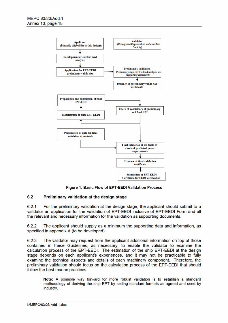
MEPC 63/23/Add.1 Annex 10, page 19
I:\MEPC\63\23-Add-1.doc
6.3 Final validation 6.3.1 The final validation process as a minimum shall include the check of ship electric load analysis to ensure that all electric consumers are listed; their specific data and the calculations in the power table itself are correct and are supported by sea trial results. If necessary, additional information has to be requested. 6.3.2 For final validation the applicant shall revise the EPT-EEDI Form and supporting documents as necessary, by taking into account the characteristics of the machinery and other electrical loads actually installed on board the ship. The EEDI condition at sea trials shall be defined and the expected power requirements in these conditions documented in the EPT. Any changes within the EPT from design stage to construction stage should be highlighted by the shipyard. 6.3.3 The preparation for the final validation includes a desk top check comprising:
.1 consistency of preliminary and final EPT; .2 changes of service factors (compared to the preliminary validation); .3 all electric consumers are listed; .4 their specific data and the calculations in the power table itself are correct; and .5 in case of doubt, component specification data is checked in addition.
6.3.4 A survey prior to sea trials is performed to ensure that machinery characteristics and data as well as other electric loads comply with those recorded in the supporting documents. This survey does not cover the complete installation but selects randomly a number [to be defined] of samples. 6.3.5 For the purpose of sea trial validation, the surveyor will check the data of selected systems and/or components given in the special column added to the EPT for this purpose or the predicted overall value of electric load by means of practicable measurements with the installed measurement devices. 7 ISSUANCE OF THE EPT-EEDI STATEMENT OF VALIDATION 7.1 The validator should stamp the EPT-EEDI Form "as Noted" after it validated the EPT-EEDI in the preliminary validation stage in accordance with these Guidelines. 7.2 The validator should stamp the EPT-EEDI Form "as Endorsed" after it validated the final EPT-EEDI in the final validation stage in accordance with these Guidelines.

MEPC 63/23/Add.1 Annex 10, page 20
I:\MEPC\63\23-Add-1.doc
APPENDIX 3
ELECTRIC POWER TABLE FORM FOR ENERGY EFFICIENCY DESIGN INDEX (EPT-EEDI FORM) AND STATEMENT OF VALIDATION
Ship ID: IMO No.: Ship's Name: Shipyard: Hull No.: 5 Miles Applicant: Validation Stage:
Name: Preliminary validation Address: Final validation Summary Results of EPT-EEDI
Load Group
Seagoing Condition EEDI Calculation Guidelines
Remarks Continuous Load (kW)
Intermittent Load (kW)
Ship Service and Engine-room Loads Accommodation and Cargo Loads Total installed load Diversity Factor Normal seagoing load Weighted average efficiency of generators PAE Supporting Documents Title ID or Remarks Validator details: Organization: Address: This is to certify that the above-mentioned electrical loads and supporting documents have been reviewed in accordance with EPT-EEDI Validation Guidelines and the review shows a reasonable confidence for use of the above PAE in EEDI calculations. The date of review: Statement of validation No. This statement is valid on condition that the electric power characteristics of the ship do not change. Signature of Validator Printed Name:
***


