Subcourse No 15 1 - Nike missile 5. FIELD MAINTENANCE SHOPS 1,2, AND 3, AND EMERGENCY CONTACT UNIT...
25
LESSON 5. FIELD MAINTENANCE SHOPS 1,2, AND 3, AND EMERGENCY CONTACT UNIT MMS Subcourse No 15 1 .................. Nike Missile and Test Equipment Lessonobjective ...................... To give you a general knowledge of the purpose, capabilities, physical description, and basic function of the test consoles comprising shops 1,2, and 3, to include console layout, types of test modules used during operation of the shops, and maintenance problem areas. Credit Hours ........................ Four TEXT 1. INTRODUCTION. a. General, The test equipment used to support the Nike Hercules and improved Nike Hercules battery is identified by two major areas of use. One group is the missile test equipment which is used to test, troubleshoot, and repair the missile and launching equipment. This equipment was covered in lesson 4. The other group which is used to test, troubleshoot, and repair assemblies from equipment in the radar course directing central (RCDC) will be discussed in this lesson. The equipment in both groups is used by direct support, general support, and depot maintenance personnel to keep the Nike batteries in a combat ready status. Efficient use of this test equipment is extremely important in keeping the Nike battery prepared to engage hostile forces. b. Electronic shops 1, 2, and 3. Part of the support maintenance test equipment, also referred to as lieid maintenance test equipment, is housed in three van-type trailers designated as electronic shop 1, electronic shop 2, and electronic shop 3. These shops contain console mounted test equipment and accessor- ies. At permanent support or depot maintenance installations, these consoles may be removed from the vans and placed in a shop building lo facilitate better work flow and production control. The consoles in each shop are referred to as test positions. Positions 1 , 2 , and 3 are in shop 1; positions 4 and 5 are in shop 2; and positions 6 and 7 are in shop 3. Test equipment mounted in various panels of each position is classified into three categories as follows: (1) Government issue items, such as multimeters and vacuum tube voltmeters. (2) Contract purchase items (commercial test equipment), such as signal generators and frequency counters. (3) Special engineer design circuits or actual circuits found in the RCDC equipment. MMS 151,5-P1
Transcript of Subcourse No 15 1 - Nike missile 5. FIELD MAINTENANCE SHOPS 1,2, AND 3, AND EMERGENCY CONTACT UNIT...

LESSON 5. FIELD MAINTENANCE SHOPS 1,2, AND 3, AND EMERGENCY CONTACT UNIT
MMS Subcourse No 15 1 . . . . . . . . . . . . . . . . . . Nike Missile and Test Equipment
Lessonobjective . . . . . . . . . . . . . . . . . . . . . . To give you a general knowledge of the purpose, capabilities, physical description, and basic function of the test consoles comprising shops 1,2, and 3, to include console layout, types of test modules used during operation of the shops, and maintenance problem areas.
Credit Hours . . . . . . . . . . . . . . . . . . . . . . . . Four
TEXT
1 . INTRODUCTION.
a. General, The test equipment used to support the Nike Hercules and improved Nike Hercules battery is identified by two major areas of use. One group is the missile test equipment which is used to test, troubleshoot, and repair the missile and launching equipment. This equipment was covered in lesson 4. The other group which is used to test, troubleshoot, and repair assemblies from equipment in the radar course directing central (RCDC) will be discussed in this lesson. The equipment in both groups is used by direct support, general support, and depot maintenance personnel to keep the Nike batteries in a combat ready status. Efficient use of this test equipment is extremely important in keeping the Nike battery prepared to engage hostile forces.
b. Electronic shops 1 , 2, and 3. Part of the support maintenance test equipment, also referred to as lieid maintenance test equipment, is housed in three
van-type trailers designated as electronic shop 1, electronic shop 2, and electronic shop 3. These shops contain console mounted test equipment and accessor- ies. At permanent support or depot maintenance installations, these consoles may be removed from the vans and placed in a shop building lo facilitate better work flow and production control. The consoles in each shop are referred to as test positions. Positions 1 ,2 , and 3 are in shop 1; positions 4 and 5 are in shop 2; and positions 6 and 7 are in shop 3. Test equipment mounted in various panels of each position is classified into three categories as follows:
(1) Government issue items, such as multimeters and vacuum tube voltmeters.
(2) Contract purchase items (commercial test equipment), such as signal generators and frequency counters.
( 3 ) Special engineer design circuits or actual circuits found in the RCDC equipment.
MMS 151,5-P1

4 5
Servo test set AN/MPM48A--position 3 Telephone handset Servo test set AN/MPM47-position 2 Computer test set AN/MPM45- position 1 Power supply set AN/MSQ-31 Storage cabinet Personnel heater Electrical test and maintenance table 1
9 Electrical test and maintenance. table 2 10 Electrical test and maintenance table 3 11 Utility cabinet 12 Access ladder 13 R& platform 14 Oscilloscope dolly 15 Oscilldscope
Figure I . Electronic shop 1 - cutaway view.
c. Emergency contact unit. The other suppoLt maintenance test equipment, consisting of unmounted test equipment, is housed in an M109 shop van. Tlus van is referred to as the emergency contact unit (ECU). The ECU is used for on-site testing of HIPAR assemblies which are NOT easily movable to electronic shops 1 , 2, and 3. Shop 3 will be covered in a separate paragraph from shops 1 and 2 because shop 3 employs a different scheme of operation.
2. DESCRIPTION OF SHOP 1 AND SHOP 2.
a. General. The major assemblies of electronic shop 1 (fig 1) are the computer test set AN/MPM45
(position l ) , servo test set AN/MPM47 (position 2), servo test set AN/MPM48A (position 3), and the power supply set AN/MSQ-3 1 . The major assemblies of electronic shop 2 (fig 2) are the radar test set AN/MF'M43 (position 4), electrical power test set AN/MPM42 and radar test set AN/MPM-37A (position 5) , and power supply group OS-1065/MPM-34. Each test set is used to test assemblies having common or closely related functions and to determine the quality of operation and acceptability of the assembly. The power supply sets in both shops supply DC voltages, preknock and sync pulses, and distribute AC voltages to the test sets. Each test set is independently operated and contains facilities for controlling the magnitude of input power from the power supply sets.
MMS 151,5-F'2

2 3 4 5
1 2 3 4 5 6 I
b.
Radar test set AN/MPM-37A-position 5 Electrical power test set AN/MPM42--position 5 Telephone handset 10 Storage cabinet Radar test set AN/MPMd3-position 4 11 Oscilloscope dolly Power supply group OA-1065/MPM-34 12 Oscilloscope Storage cabinet 13 Rear platform Personnel heater 14 Access ladder
8 Electrical test and maintenance table 4 9 Electrical test and maintenance table 5
Figure 2. Electronic shop 2 - cutaway view.
Computer test set AN/MPM45 (fig 3). position. The major difference between each console is Position 1 provides test equipment for testing computer assemblies and for testing voltage regulators, amplifiers, relays, converters, reference generators, brush recorders, and oscillators of the guided missile system radar-signal simulator station AN/MPQ-36. The computer test set, as well as other test sets in shops 1 and 2, is mounted on top of an electrical test and maintenance table. The electrical test and maintenance table at each position contains storage space for manuals, patch cards, miscellaneous test equipment, and cables used at that
the type test equipment mounted in the electrical equipment cabinet panels. This provides capability for testing different units at each console.
c . Servo test set AN/MPM-47 (fig 4). Position 2 contains facilities for testing range, azimuth, and elevation indicators; acquisition and track range amplifier-control groups from the LOPAR and tracking radars; amplifiers, generators, converters, servomotors and the CRT scanners of the AN/MPQ-36 simulator.
MMS 151,5-P3
D 6283935
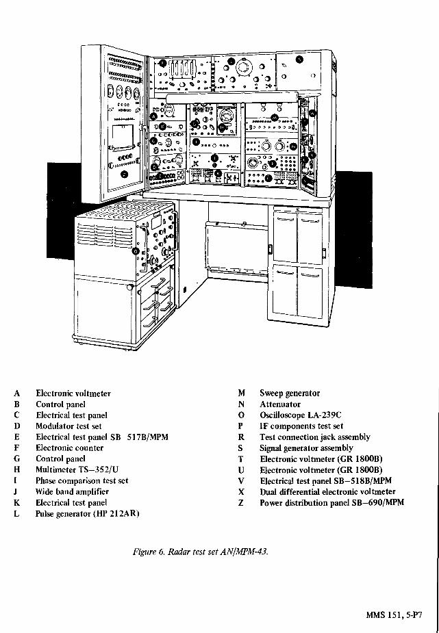
A B C D E F G H J K L M
Electronic voltmeter Electrical test panel Relay test set Electrical test panel SB-517BIMPM Zero set amplifier test set Audio oscillator TS-312/FSM-1 Electrical test panel Multimeter TS-352/U Zero set, varistor, and dc amplifier test panel Test connection jack assembly Resistance bridge Megohmmeter
N 0 P R S T U V W X Z
Continuity and insulation test set Oscilloscope Electrical test panel Test connection jack assembly Test connection generator panel Electronic voltmeter Control panel Servo modulator test set Electrical test panel SB-S18B/MPM Electronic counter Power distribution panel SB-690/MPM
Figure 3. Computer test set ANfMPM-4.5.
MMS 151,5-P4
A B C D E F G H I J K L
Pulse generator Electrical test panel Sweep generator amplifier Jack assembly Electrical test panel Pulse generator Pulse generator Multimeter stop timer Range servo test set Jack assembly Control panel 4-KC signal generator dummy load
M N 0 P R S T U V W z
Electrical test panel Indicator test set Oscilloscope Jack assembly Range calibrator set Electronic voltmeter Indicator high voltage control panel Electrical dummy load Jack assembly Electrical test panel Power distribution panel
Figure 4. Servo test set AN/MYM-47.
MMS 15 1,5-P5

9d-S ‘IS1 S I W
A B C D E F G H I J K L
Electronic voltmeter Control panel Electrical test panel Modulator test set Electrical test panel SB-517BIMPM Electronic counter Control panel Multimeter TS-352/U Phase comparison test set Wide band amplifier Electrical test panel Pulse generator (HP 212AR)
M N 0 P R S T U V X Z
Sweep generator Attenuator Oscilloscope LA-239C IF components test set Test connection jack assembly Signal generator assembly Electronic voltmeter (GR 1800B) Electronic voltmeter (GR 1800B) Electrical test panel SB-518B/MPM Dual differential electronic voltmeter Power distribution panel SB-690/MPM
Figure 6. Radar test set AN/WM-43.
MMS 151,5-W

A B C D E F G H I J K
Test set subassembly Electrical test panel Pulse generator Electrical test panel Electrical test panel SB-517B/MPM Electronic counter Control panel test set Multimeter-load and pulse simulator Test connection jack assembly RF power meter Audio osqillator TS-312/FSM-1
L
M N 0 P R S T U Z
Electronic voltmeter and test connection jack assembly RF test set test set Electrical test panel Oscilloscope RF test set Power supply test set Interval timer test set Control panel Elec6ical test panel SBJ18B/MPM Power distribution panel SB690/MPM
Figure 7. Electrical power test set ANIMPM-42.
f. Electrical power test set AN/MPM-42 (fig 7). The electrical power test set provides facilities for testing :'xv voltage power supplies and regulators, high voltage silpplies, delay timers, servos, servomotors, amplifier ssemblies, and miscellaneous control panels.
g. Radar test set AN/MPM-37A (fig 8). This p u t of position 5 is used with the electrical power test 521 ANIMpM-42 to test Nike track radar high voltage p u e r supplies, modulators, and RF units. It permits ::sung of a complete RF system, which is too large to k i n g into the shop, by providmg connections through :?.c trailer wall to the RF system located outside.
h. Storage. In addition to the consoles, shops 1 and 2 contain a storage cabinet, a personnel heater, and a utility cabinet (6, 7, and 11, fig 1, respectively for shop 1). Additional storage facilities are provided in each electrical test and maintenance table. The electrical test and Sintenance table at each position as well as other storage places use an alphanumeric system of location as shown in figure 9. The vertical bays have alphabetical designations while the horizontal bays have numerical designations. There is also storage space in the rear of each electrical test and maintenance table. Each position is layed out in the same manner to facilitate rapid location of any test equipment or accessory needed by
M51S 151,5-P8
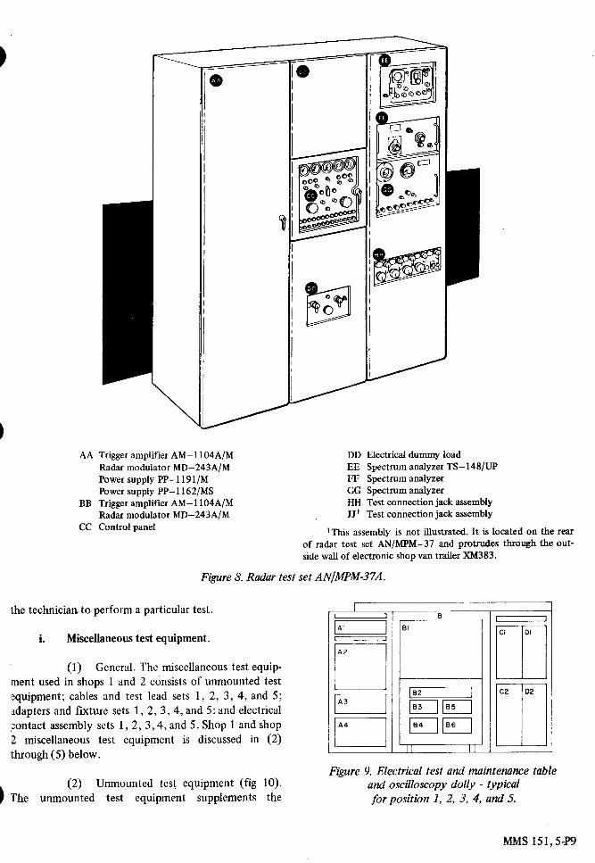
AA Trigger amplifier AM-l104A/M Radar modulator MD-243A/M Power supply PP-l191/M Power supply PP-l162/MS
BB Trigger amplifier AM-l104A/M Radar modulator MD-243A/M
CC Control panel
DD Electrical dummy load EE Spectrum analyzer TS-148/UP FF Spectrum analyzer GG Spectrum analyzer HH Test connection jack assembly JJ' Test connection jack assembly
'This assembly is not illustrated. It is located on the rear of radar test set AN/MPM-37 and protrudes through the out- side wall of electronic shop van trailer XM383.
Figure 8. Radar test set ANIMPM-37A.
the technician to perform a particular test.
i. Miscellaneous test equipment.
(1) General. The miscellaneous test equip- ment used in shops 1 and 2 consists of unmounted test equipment; cables and test lead sets 1, 2 , 3, 4, and 5 ; 3dapters and fixture sets 1, 2 , 3, 4, and 5 ; and electrical 8:ontact assembly sets 1, 2 , 3 ,4 , and 5 . Shop 1 and shop 2 miscellaneous test equipment is discussed in ( 2 ) through (5) below.
I Figure 9. Electrical test and maintenance table
and oscilloscopy dolly - typical for position 1, 2, 3, 4, and 5.
( 2 ) Unmounted test equipment (fig 10). 1 The unmounted test equipment supplements the
MMS 151,5-P9

MMS 151, 5-1` 1 0
mounted
test
equipment
in performing tests
on
reference to illustrations, shows the storage location ofassemblies . The pulse generator and receiver-gate
each cable . The 100-, 200-, 300-, 400-, and 500-seriesgenerator (12 and 14, fig 10) are stored in storagelocation A2 of the electrical test and maintenance table
TABLE I. CABLESat position 1 . The electronic multimeter and multimeterTS-352/U (10 and 11, fig 10) are stored in rear of theelectrical test and maintenance table 1 at storagelocation Al . The remaining unmounted test equipmentin figure 10 is stored in the storage cabinet (6, fig 1) .
(3)
Cables and test leads sets 1, 2, 3, 4,and 5 . Table I gives you an example of how the cablesare listed in technical manuals . This table is typical andreflects information found in technical manuals stored inthe electrical test and maintenance tables of shops 1 and2 . It shows the part number of each cable and, by
Figure 10. Unmounted test equipment.
1 Frequency meter TS-323/UR 8 Null voltage test set2 Radar test set TS-147D/UP 9 Resistance bridge ZM-4B/U3 Tube tester 10 Electronic multimeter ME-6/U4 Insulation resistance tester ZM-21A/U 11 Multimeter TS-352/U
and cable 12 Pulse generator5 Frequency-power meter ME-51/UP 13 Receiver control6 Analyzer ZM-3/U 14 Receiver-gate generator7 Test recorder
ITEM PART NO STORAGE LOCATION REFERENCE
Cable 101 8157650 2 in Al, 2 in BI, rear of 9, fig 1Cable 102 8157651 Cl, rear of 9, fig 1Cable 103 8150933 Dl, rear of 9, fig 1Cable 104 8150934 Dl, rear of 9, fig 1Cable 201 8151081 Al and 131, rear of 9, fig 1Cable 202 8151082 Cl, rear of 10, fig 1Cable 235 9140631 A4, 9, fig 1Cable 301 8151221 2inB1,11,fig1Cable 302 8151222 131, 11, fig ICable 303 8151223 Bl, 11, fig 1

20
cables are used in various combinations to perform testsat positions 1, 2, 3, 4, and 5, respectively . It can be seenfrom the accompanying table that each cable is stored ina location which makes it easily accessible to thetechnician working at the individual consoles .
(4)
Adapters and fixtures sets 1, 2, 3, 4,and 5 . An example of the test adapters used to performtests in electronic shop 1 is given in table II . The partnumber for each item and a reference to illustrationsshowing physical appearance and storage location ofeach item are included in the table . The 100-,200-, and300-series test adapters are used in various combinationsto perform tests at positions 1, 2, and 3, respectively .The 400- and 500-series test adapters are used in shop 2,at positions 4 and 5, respectively . The functional use ofeach item is given in the description column of the table .The 100-series test adapters are shown in figure 11 . Theonly improved Nike-Hercules test adapter appearing inthe 100-series components is TA-C139 and is indicatedby the INH suffix . The 200-, 300-, 400-, and 500-series
figure 11 . 100-series test adapters.
components are not shown but are stored in a locationeasily accessible to the technician working at therespective consoles .
TABLEII. TESTADAPTERS
MMS 151, 5-PI l
ITEM PART NO
FIG REFPHYSICAL
APPEARANCESTORAGELOCATION DESCRIPTION
TA-101 8156115 22, fig 7 E7, rear of 2.2-megohm9, fig 1 standard re-
sistor adapterTA-102 8156116 22, fig 7 E7, rear of 10-megohm
9, fig 1 standard re-sistor adapter
TA-103 8151653 26, fig 7 2 in E7, Tip jackrear of 9, adapterfig 1
39 9980829 (not shown) F8, rear of Adapter(INH) 9, fig 1
1 TA-136 9 TA-130 15 TA-113 20 TA-116 TA-1222 TA-135 10 TA-125 TA-114 21 TA-138 TA-1233 TA-128 11 TA-126 TA-124 22 TA-101 23 TA-1324 TA-129 TA-127 16 TA-107 TA-102 24 TA-1195 TA-141 12 TA-137 17 TA-111 TA-109 25 TA-1216 TA-106 13 TA-133 18 TA-108 TA-110 26 TA-1037 TA-115 14 TA-112 19 TA-120 TA-117 27TA-1058 TA-118 28 TA-134

j. Electrical contact assembly sets 1 , 2, 3, 4, and 5.
9140712 9140745 9140754 9140767
(1) The electrical contact assembly sets 1, 2, and 3 (patch cards) of electronic shop 1 are used at positions 1, 2, and 3, respectively. Sets 4 and 5 of electronic shop 2 are used at positions 4 and 5, respectively. Patch cards for position 1 are stored in drawers C1, C2, D1, and D2 (fig 1) of electrical test and maintenance table 1 . Patch cards for positions 2, 3, 4, and 5 are stored in drawers C1, D1, and D2 of electrical test and maintenance tables 2, 3 , 4 , and 5 , respectively. Each patch card is applicable to a particular test as specified in technical bulletins covering the test being performed.
~~
GS58611 2 GS-57536 2 GS-56957 5 GS-183 53 3
(2) A patch card consists of three phenolic blocks mounted on a common metallic frame. Metallic contact studs are mounted in perforations on the phenolic block. The contact studs are cross-connected as required on the rear of the patch card. When the patc?l\ card is placed in the patching panel (located on panel’Z ) at each position), the door of the patchng p a n e i x closed and patch card contact studs make contact with similar studs on the patching panel. This establishes connections only for tliose circuits of the test set required for testing a particular assembly. Patch cards are slotted on each side to prevent incorrect insertion. Each patching panel contains a lever operated interlock switch which, when closed, provides ground to relays so that the test set can be energized to ON, provided a patch card is inserted and the door interlocks are closed.
TM 9-1400-250-34/2/2 TM 9-1400-250-35/2/3 TM 9-1400-250-34/5/4 TM 9-1400-250-34/3/2
3. OPERATION AND USE OF SHOPS 1 AND 2.
21 16 Sep 64 c1 4 15 Sep 64 5 28 Oct 64 9 28 Apr 64
a. General. When a chassis, assembly, or subassembly (referred to as units under test (UUT)), arrives at a Nike direct or general support unit, it has a DA Form 2407 (maintenance request) attached to it. The job order clerk assigns the chassis a control number. to identify it with the 2407. The chassis is passed on to an inspection section where it is given a visual inspection to determine if any components are missing or broken,
then an inspection tag is attached to the chassis. The position used to test the chassis is determined from a master technical bulletin and the chassis is sent to the appropriate shop position for testing and repair.
b. Master technical bulletin. Master TB 94900-250-35/1 is used to determine whch position of shop 1 , 2, or 3 is used to test the UUT. TB 94900-250-35/2 is used to determine which missile and launcher test equipment is used to test UUT’s or assemblies from the launching area. Table 111 gives you an example of the information found in master TB 94900-250-35/1. In this table the UUT’s are indexed by part number sequence. The part number stamped on the chassis to be tested will identify the UUT, and the position column of table 111 identifies the console used to test the UUT. The TM or TB number column identifies the manual or bulletin to be used when performing the test. The chapter column identifies the chapter of the TM or TB which concerns the particular UUT. The date and latest change number of the TM or TB is also given in the master TB.
c. Use of technical manuals. At the appropriate position the correct TM or TB is selected for testing the UUT. Each chapter in the TM or TB contains the following information.
(1) Purpose of the test. This section explains what the test checks.
(2) Test equipment. This section lists the panels of the console, miscellaneous test equipment, cables, adapters, rind patch cards which the technician will need to perform the test. From this information all the test equipment and accessories can be selected from their storage locations.
(3) Preparation for test. This section contains information on how to condition the console for making the test and how to connect the UUT to the console. It also tells which patch card to insert in the patching panel. From this information the technician
TABLE III. MASTER TECHNICAL BULLETIN
PARTNO I SPECNO 1 POSITION TMORTBNO 1 CHAP! DATE \CHANGENO
MMS 151,5P12
UUT
TRANSFORMER ~
S1 A 1
-
RELAY ASSY L
CONSOLE POWER
( 2 )
B
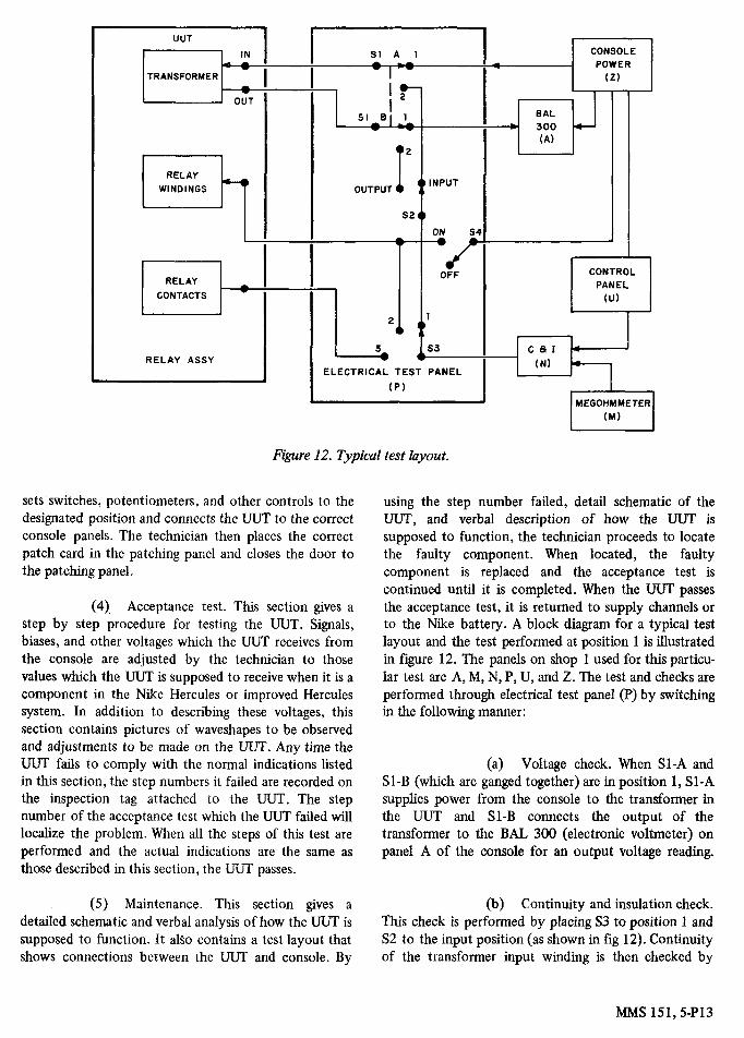
Figure 12. Typical test layout.
EAL 300 (A)
sets switches, potentiometers, and other controls to the designated position and connects the UUT to the correct console panels. The technician then places the correct patch card in the patching panel and closes the door to the patching panel.
(4). Acceptance test. This section gives a step by step procedure for testing the UUT. Signals, biases, and other voltages which the UUT receives from the console are adjusted by the technician to those values which the UUT is supposed to receive when it is a component in the Nike Hercules or improved Hercules system. In addition to describing these voltages, this section contains pictures of waveshapes to be observed and adjustments to be made on the UUT. Any time the UUT fails to comply with the normal indications listed in t h~s section, the step numbers it failed are recorded on the inspection tag attached to the UUT. The step number of the acceptance test which the UUT failed will localize the problem. When all the steps of this test are performed and the actual indications are the same as those described in this section, the UUT passes.
(5) Maintenance. This section gives a detailed schematic and verbal analysis of how the UZiT is supposed to function. It also contains a test layout that shows connections between the UUT and console. By
using the step number failed, detail schematic of the UUT, and verbal description of how the UUT is supposed to function, the technician proceeds to locate the faulty component. When located, the faulty component is replaced and the acceptance test is continued until it is completed. When the UUT passes the acceptance test, it is returned to supply channels or to the Nike battery. A block diagram for a typical test layout and the test performed at position 1 is illustrated in figure 12. The panels on shop 1 used for this particu- lar test are A, M, N, P, U, and Z. The test and checks are performed through electrical test panel (J?) by switching in the following manner:
(a) Voltage check. When SI-A and S1-B (which are ganged together) are in position 1, S1-A supplies power from the console to the transformer in the WT and S1-B connects the output of the transformer to the BAL 300 (electronic voltmeter) on panel A of the console for an output voltage reading.
(b) Continuity and insulation check. This check is performed by placing S3 to position 1 and S2 to the input position (as shown in fig 12). Continuity of the transformer input winding is then checked by
MMS 151,5-P13

placing S1-A and B to position 2 and reading theresistance on panel (M) . Continuity and insulation of thetransformer output winding is checked by placing S2 tothe output position and reading the resistance on panel(M) . Connection of panel (M) and (N) are controlled atpanel (N) .
(c)
Relay check . Continuity of therelay windings is checked by placing S3 to position 2and reading the resistance on panel (M) . The open circuitresistance of the relay contacts is checked by placing S3to position 3 . Both positions of S3 connect the relay topanel (N) . When S3 is in position 3, S4 can be placed ONto energize the relay and the closed circuit resistance ofthe relay contacts is read on panel (M) .
4 .
DESCRIPTION OF SHOP 3 .
a .
General. The addition of shop 3 (fig 13) tothe Nike field maintenance test equipment (FMTE) wasnecessary when TTR, HIPAR, and AN/MPQ-T l were
MMS 151,5-P14
6
Figure 13. Trailer mounted electronic shop 3 - cutaway view.
Console 7Storage cabinet for console 6Vehicular compartment heaterAir conditionerDistribution boxConsole 6Storage cabinet for console 7Utility and personnel locker cabinetUtility cabinet
added to the basic Nike Hercules system . The conversionof a Nike Hercules FMTE system to an improved NikeHercules FMTE system consisted of adding electronicshop 3 to the basic system and modifying electronicshops 1 and 2 . The modifications to these electronicshops consisted of equalizing the workload on some ofthe consoles by transferring certain units under test fromthese consoles to the new electronic shop 3 . In addition,some of the improved Nike Hercules system chassis arechecked in electronic shops 1 and 2, but most of theseunits were assigned to consoles which had lightworkloads . Shops 1 and 2 had to be modified to receivethe newly assigned UUT's . The modifications consistedprimarily of removing the technical bulletins, testadapters, and patch cards of the units under test whichwere transferred to electronic shop 3 . At the same timenew technical bulletins, patch cards, and test adapterswere added for the newly assigned UUT . One hundredand ninety-five units have been assigned to electronicshop 3 . Eighteen of the 195 units are NikeAjax/Hercules units which reduced the traffic on

consoles in electronic shops 1 and 2. Twenty-five improved Nlke Hercules units, excluding HIPAR, were assigned to consoles I , 2, 3, and 5 in electronic shops 1 and 2. These units are modified units of the basic Nike Ajax/Hercules systems and therefore may be checked on these consoles without any wiring changes being made in the consoles. The 18 units transferred to electronic shop 3 consist primarily of large turnover units such as IF amplifiers, AFC units, synchronizers, and IF-to-video detectors. This assignment is tentative and subject to change as a result of system changes. The layout of the equipment in electronic shop 3 is shown In figure 13. Two separate and independent test consoles with associated storage cabinets are provided. The test consoles are basically identical; the storage cabinefs are similar, varying only ~- in -. storage de tds . The two consoles are designated consoles 6 and 7. Console 6 is located on the curbside of the trailer while console 7 is located on the roadside of the trailer. The test consoles and storage cabinets are designed to permit ready installation at permanent locations. Each console in electronic shop 3 contains a limited number of test equipment panels w h c h allows it to test a specitic category of units. As test requirements change, dictating a different or modified test equipment lineup or perhaps even a complete change in the testing capability of an individual console, these plug-in test equipment panels may be replaced by a different group of panels. The unused panels may then be mounled in the storage cabinets which are specifically designed to accept them. This capability of ready console conversion, coupled with the facility of storage of aiternate test equipment panels, provides the flexibility necessary for modifica- tions.
-.
b. Console 6.
NOTE: Information in ( l ) , (2) , 1-71, (4), ~ n t d (7) below upplirs to console 7 {jig 15) US u d l US coiisole 6.
(1) General. Conwle 6 (fig 14) in electronic shop 3 is compomt of rectmqii ii modules, 7 inches hgh by 19 inches wide Ihe modules are mounted in five bays, 60 inches h i ~ h by 19 inches wide. The vertical bays are des,igndrcii A tiirough b (left to right facing the console). i n the individual bays, each slot is assigned a number begiririirip with i a t the top and proceeding downward. T h s aiso ,~ppbcs to the small cable connection areas, or reeiitiq \ t r i p , \tiuch occupy space between modules Ih? idefitiiicnhon (for the purpose of locating any expow! c o n ~ l i : drea) IS p e n by a letter followed by a number Thus identification is placed on the console frame to the right wle of the space and any module placed wirhm that space assumes
the designated area identification. For example, the third area from the top in the third bay from the left is called C3. When the console operator is instructed to perform some type of' operation at panel C3, he will be able to find that location immediately by observing the front of the console. The associated ordnance number is also displayed on the front panel of each module. A small removable plate bearing the ordnance number is mounted on the upper right-hand portion of the module. When the ordnance number is caused to change, the plate mounting is loosened behind the panel, and the plate is replaced with one bearing the new ordnance number.
(2) Location of the connected UUT and test accessories. The connectors for the interconnection of the UUT and the console are located just above the workbench on the electrical test panel located in area A4. The operator is normally positioned in front of area C with the UUT in front of area B7. This position leaves the work surface directly in front and to the right free for use by the operator. The test consoles are so arranged that the outer bays and center bays below the work surface contain those items of test equipment seldom used. The center three bays above the work surface contain those items normally used by the operator. Thus the operator has within easy reach and ready vision all the equipment normally used during a test procedure.
(3) Location of the patch panel. The electrical power distribution panel is located in area A1 (fig 14) and contains the circuitry for energizing the console. No attempt was made toward programming the operation of this panel. Ths unit also contains the test connection patching panel which is in area A3. The patching panel is the same multicontact switch assembly used on shop 1 and 2 consoles. The insertion of the individual prewired patch card associated with each unit under test provides the proper interconnections of the '8
UUT to the test console. The patching switch is used in electronic shop 3 because it is still the most reliable and economical device available for accomplishing a large scale switching operation. The remaining units within the consoles of electronic shop 3 may be divided into four functional groups: the console programming equipment, display and measuring equipment, special purpose test equipment and power supplies. The location of these units is discussed in (4) through (7) below.
(4) Location o f the console programming equipment (CPE). A card reader and an associated remote switching control, which comprise the console
MMS 151,5-P15

GENERATOR REMOTE SWlTCHlNQ PULSE GROUP CONTROL GENERATOR
ELECTRICAL TIME TEST PANEL STRETCHER
POWER REMOTE \ y;;V /
SWITCHING ANALYZER- FREOUENCY SELECTOR DIGITAL CONTROL INDICATOR COUNTER CONTROL SUPPLY
Figure 14. Console 6 - location diagram.
programming equipment, are Iocated in areas A10 and C7, respectively. The card reader may be pulled forward on drawer slides to facilitate maintenance procedures. The remote switching control is centrally located within the console where it is easily accessible to the console operator.
(5) Location of the display and measuring equipment (DAME). The units within the display and measuring equipment are located in various places in the consoles. The digital display indicator, the waveform analyzer monitor, and the- time stretcher are centrally located withn the console in areas C5, D5, and D7, respectively. Thus the console operator has within easy reach and ready vision all the test and monitoring equipment normally needed during any test procedure. An electronic digital counter is located in area C1 and a multimeter, consisting of three sections, is located in areas E9 through El 1 of the console. The outputs of the electronic digital counter and the multimeter are displayed on the digital display indicator; therefore, these units do not have to be centrally located.
i
(6) .Location of the special purpose test [ equipment (SF'TE). The special purpose test equipment 1
r is located in areas B1 through B8, C3, D1, D3, and E l \ \ through E8. These panels are specifically designed to test I
a particular category of units. For console 6 these units t. are designed to check IF amplifiers, AFC units, and I video detectors. The panels have been standardized in i layout, dimension, connectors, and mounting facilities. As additional special test equipment items are required for checking units of the improved Nike Hercules, they , may be readily interchanged with those initially provided. They may be stored in the storage cabinets when not in use and, as required, interchanged with units in the console. The small connector panels or reentry strips between the large panels facilitate interconnecting coaxial type signal leads to the signal switching system. These panels also provide direct access to input and output signals which may be required during maintenance and repair operations on a faulty UUT.
i I
i \ I
1
.
(7) Location of power supplies. The DC
MMS 151,5-P16

-
ELECTRICAL ELECTRONIC DIGITAL DISPLAY REMOTE SWITCHING WAVEFORM
DUMMY LOAD
BLOWERS 0-600V DC POWER MULTIMETER MULTIMETER
POWER SUPPLIES POWER SUPPLIES EQUIPMENT (SECTION A1 (SECTION 8 ) CARD READER ?ZSO, OR t ISDV DC
DRAWER
Figure 15. Console 7 - location diagram.
power supplies and voltage regulators arelocated in areas B9, B10, C9, D9 through D11. and E12. The power supplies are located below the workbench and are not accessible to the operator for maintenance purposes. Also below the workbench and located in area C10 are the blowers wluch provide cooling and ventilation of the units witlun the console.
c. Console 7 .
(1) As depicted in figure 15, the console programming equipment, the display and measuring equipment, and the power supply areas are identical on consoles 6 and 7. The difference in console panels occurs in the special purpose test equipment areas of the B bay, E bay, and areas D1 and D2. These special test equipment panels are used to check video amplifiers, DC amplifiers, pulse'generators, relay assemblies, and power supplies. The overall operation of console 7 is identical to the operation of console 6 except for the special purpose test equipment.
(2) All of the panels within the test consoles of electronic shop 3 are constructed to utilize a new concept in the layout of equipment. Each major
panel has one or more subassemblies called minispecs. A minispec is a module which contains usually one complete circuit such as an IF amplifier, a pulse generator, or a DC amplifier. A minispec subassembly is 1-1/2 inches wide by 8-1/2 inches long by 3-1/2 inches lugh. Up to five tube stages may be mounted on this subassembly depending on the complexity of the circuit. In special circuits a double minispec, wluch is twice the width of a single minispec, is used in order to get a complex circuit on a subassembly. All the minispecs within a panel may function together to produce an output signal, as in the pulse generator, or they may perform separate and independent functions as in the amplifier assembly. The individual minispec contains numerous test points making it possible to check nearly every point within the circuit. For troubleshooting purposes, the minispec is raised from the surrounding units and locked in this position for easier accessibility. The minispec is less difficult to replace than a subassembly of a panel, thus making maintenance and repair easier.
5. FUNCTION OF SHOP 3 CONSOLES (FIG 16).
a. General. In order to simplify test procedures
MMS 151,5-P17

PRIMARY POWER *
1 I ' I I
INTERLOCK AND PATCH POWER TO CONSOLE UNITS
POWER * CARD ' c CIRCUITS
DISPLAY AND MEASURING EOUIPMENT A L - - - - - - - - - -
-------------
Figure 16. Electronic shop 3 - block diagram.
A CARD
SELECT SIGNAL ---------
F E C I A L PURPOSE TEST EOUIPMENT 1
and have a maximum testing rate of UUT's on a pass-fail basis, a certain degree of automatic console operation is desired. The automation of the setup controls and subsequent positioning or repositioning of controls during the control of a test procedure provides the greatest return in terms of test time saved at a reasonable cost and equipment complexity. With these features in mind, the consoles in electronic shop 3 have been designed to operate semiautomatically. However, facili- ties are provided for the consoles to be completely manually operated by the console operator for manual repair and maintenance of defective units. The test consoles contain test equipment panels including a number of selector switches that provide the proper output signals and adjust the output measuring equipment to the proper range and characteristics. These switches are rotary type with an actuating solenoid positioning device to position each switch. The console programming equipment functions to position these rotary selector switches to the proper positions in the correct sequence. In addition, the selector switches may be manually operated if required. The functional units within the consoles of electronic shop 3, i.e., the interlocks and power circuits, the console programming equipment, the special purpose test equipment, and the
AND COUNTER CIRCUITS
7
display and measuring equipment, are discussed in -Ya- graphs b thru e below.
WAVEFORM ANALYZER- MONITOR
b. Interlock and power circuits. These circuits (fig 16) provide the necessary protection and power for operating the console. The patch card for each UUT provides the power interconnections to program the three variable power supplies (0 to 600 volts) and to verify selection of the correct program card. The patch card establishes continuity with verification circuits in the remote switching control. The verification circuit determines that the correct program card for peiforming test on the UUT is selected by the card reader.
c. Console programming equipment.
(1) To accomplish its required function, the console programming equipment has the capability of addressing a particular panel and positioning a selected switch to any one of a number of discrete positions. The console programming equipment then proceeds to position additional switches in the same, panel or other panels in the proper sequence until a complete test procedure has been accomplished. To make effective use of the console programming
MMS 151,5-P18

CARD SELECT
COLUMNS ( I AND 2 1 \
END OF CARD
INFORMATION I
12 I I
0 I
2
ROWS 4 5 6 7 8 9
C OM PAR AT 0 R LIMITS I N FOR MAT I0 N
Figure 17. Standard program card.
equipment, as many test equipment controls as possible must be operable in discrete increments. As shown in figure 16, the console programming equipment consists of a program card, card reader, and a remote switchmg control panel.
(2) All test condition information for semiautomatic console operation is placed on the program card (fig 17) by holes punched in the card. This card is a standard punched card, 3-114 by 7-318 inches, containing 12 rows and 80 columns. The four classes of information contained on this card are: card select, switch position, comparator limit, and end of card. The card select information is always punched in columns 1 and 2 and is used to find the correct card for a particular UUT. The switch ~os i t ion -in- . is punched in columns 3 and 4. This information is used to select a particular panel, switch, and switch position for the test to be performed. The next eight columns are used to program the comparator limit information which establishes the upper and lower limits of the parameter to be tested. Programming of the switches and the h i t s completes one test condition. As many test conditions as necessary to check the UUT may be programmed in the same manner. The final information punched on a card is the end of card information. This information is punched either in the last two columns of the card,
_--
columns 79 and 80, or at the end of a particular test if the test ends before all columns of the card are used. If all test conditions have been completed, the end of card punches will provide an end of test signal which will be displayed by a front panel indicator on the remote switchmg control. If another card is required to complete the test, the end of card punches will contain card select information which is used to select the next card required to continue the test.
(3) The program cards are stored in the hopper of the card reader (fig 18). Single cards are automatically picked from the bottom of the deck with a picker knife and pushed into feed rollers. Four sets of clutched rollers transfer cards up the chute to the rotating drum. The card is clamped onto the drum and rotated to the read station. At the read station 12 star wheels are in a position to drop into the holes in the card. Microswitches on the star wheel arms generate program signals when the wheel drops into the punched holes. After the card is read it is rotated to the follow read station and dropped back into the hopper. The program signals from the card reader (fig 16) are applied to the remote switching control which contains logic relay circuits to convert all signals from the card reader into commands to be applied to the desired panel within the console. It is the remote switching control whch
MMS 151,5-P19

READ HEAD READ HEAD
C A R D CARD R
CARD S
BLANK STATION
FOLLOW READ STATION C L
ORIGINAL POSITION OF CARDS RE-READ
CARD
HOPPER
P
!.
FINAL POSITION OF CARDS RE-READ
Figure 18. Card reader.
actually addresses the selected console panel, selects a particular switch on the selected panel, and then rotates it to the correct position. Control signals are applied between the remote switching control and nearly every panel within the console. In order for the card reader to select the correct series of program cards for a particular test, card select signals are coupled between the remote switching control and the patch card. The card reader searches for the first program card until the output signals from the card reader energizes a particular combination of logic relays whose contacts complete a patch through the patch card and energizes a card selected relay in the remote switching control. When the first program card of test series has been selected, a CARD SELECTED visual indication is given to the console operator indicating that the check of the UUT may progress.
d. Special purpose test equipment. This special purpose test equipment consists of specifically designed panels which test a particular category of units such as IF amplifiers, AFC units, pulse generators, and DC control units. It is these special test equipment panels which make the two consoles in electronic shop 3 differ. The console programming equipment addresses the panels required for checking the UUT and establishes the proper test signal output which is to be applied to the UUT. The special purpose test equipment consists of synchronizer units, IF and RF signal generators, pulse generators, DC amplifiers, and associated control circuits. The special purpose test equipment has been broadly designed so that it is capable of generating all signals for the improved Nike Hercules system including TRR, HIPAR, and the AN/MPQ-T1 simulator, as well as
.CARD T
-CARD U
C A R D V
providing a margin for future growth as required when the improved Nike system is modified. Test signals between the UUT and the special purpose test equipment are applied through a crossbar switch. The crossbar switch is positioned by signals from the remote switching control to set up a path for signals between the UUT and the console equipment. The crossbar switch permits establishment of alternate signal paths, which are required for different test conditions and it also eliminates external cabling between the UUT and the console test panels.
e. Display and measuring equipment.
(1) General. The signals from the UUT are applied through the crossbar switch to the display and measuring equipment (DAME). The DAME system consists of a timer stretcher, a waveform analyzer- monitor, a digital counter, a digital multimeter, and a digital readout circuit.
(2) Time stretcher and waveform analy- zer-monitor. The time stretcher and waveform analyzer- monitor are used to interpret pulsed signal information. These two units permit pulse characteristics such as pulse duration, amplitude, rise time, and fall time to be measured. The time stretcher converts the pulsed signals to an increased time base so that accurate measurements of the pulse characteristics may be made. For example, a 1 -microsecond pulse can be stretched to a pulse duration of 1 second, an increase of one million in time base. The waveform analyzer-monitor actually performs the measurement of the pulse characteristics and applies the measured information to either the digital multimeter or
MMS 151,5P20

counter, depending on the characteristics being meas- ured. The time stretcher and waveform analyzer-monitor have the advantage of greater frequency coverage, programmable operation, and simple pushbutton control when manually operated. In addition, the numerical readout of measured parameters requires no interpreta- tion of the results on the part of the operator. They panels provide equipment which requires a minimum of decisionmaking on the part of the operator.
(3) Digital multimeter and digital counter. The digital multimeter and the digital counter are the only two measuring instruments within the consoles of electronic shop 3. These instruments are controlled by the console programming equipment in the semiautoma- tic mode of console operation but they may be manually controlled if necessary. The signal inputs to these measuring units are from the waveform analyzer-monitor when pulsed signals are being measured or from the crossbar switch and sometimes the patch card if continuous wave signals such as AC voltages, DC voltages, resistances, or ratios are being measured., The digital multimeter and digital counter are commercial instruments modified for application in this systea. The output from the digital multimeter or digital cowter, depending on the measurement being made, is applied to the digital readout circuits.
(4) Digital readout circuits. The digital readout circuits display, in numerical form, all the measured quantities of both the test console and the UUT, as shown in figures 14 and 15. In addition to the numerical value of the measured quantity, the characteristic of this quantity is displayed such as volts, ohms, microseconds, etc. The numerical readout value of the signal from the UUT is also compared in these circuits with limits from the console programming equipment which are established by punches in the program card. A visual PASS cr FAIL signal is given to the console operator depending on whether or not the signal from the UUT is within programmed limits. A PASS signal permits the semiautomatic console opera- tion to continue, but a FAIL signal or the absence of a PASS signal stops the console programming equipment. If a FAIL condition occurs, the operator can perform troubleshooting procedures whde observing the digital readout display. Once the trouble is cleared and a PASS signal is obtained the operator may then place the console programming equipment back into semiautoma- tic operation.
6. OPERATION AND USE OF SHOP 3. The general pattern of testing WT’s in shop 3 is similar to shops 1 and 2. However, since switch positions and most cable
connections are made automatically, the operator’s main function is to connect the UUT to the console, press buttons, and observe indications on the readout equipment as instructed by technical manuals. The technical manuals covering the WT’s tested in shop 3 are selected by using the master technical bulletin and
.they contain the same type data hi shop 1 and 2 technical manuals; i.e., purpose of test, preparation for test, acceptance test, and troubleshooting aids. The purpose of the test and preparation for test are the same as shops 1 and 2, while the acceptance test gives the number of each test condition, refers to a location by area, number, and gives the operation to be performed or observations to be made in that area. The acceptance test also gives the purpose of the test condition. While the acceptance test is being performed, the test equipment is in semiautomatic operation. If the UUT fails the acceptance test, the repairman performs the troubleshooting aids listed in the TM. While performing the troubleshooting aids the test equipment is operated manually. Data given in the troubleshooting aids allow the operator to set each switch and control. If the switches on the console are in the position prescribed by the TM, the trouble is in the UUT. If not, the trouble is in the console.
7. EMERGENCY CONTACT UNIT (FIG 19). The support maintenance test equipment used to test some HIPAR assemblies is housed in the emergency contact unit (ECU). This test equipment is normally used by maintenance contact teams which are dispatched from a direct support maintenance shop to the Nike site. The men dispatched with the ECU should be well qualified technicians holding a 23U MOS. The ECU contains test equipment necessary to analyze and evaluate the HIPAR system performance. Many of the test equipment items stored in the ECU are of the commercial type including a differential voltmeter, a tube tester, an oscilloscope, a vacuum tube voltmeter, and a multimeter. Many other ECU test equipment items are made especially for the HIPAR, such as the precision slotted waveguide, a slide screw tuner, a slotted line probe, and a coaxial waveguide adapter.
8. CALIBRATION. Most items of test and measuring equipment in shops 1 , 2, 3, and the ECU require calibration every 90 days. However, some of this equipment requires calibration at 180-day intervals. Many of the items of test equipment can be calibrated only by authorized calibration teams while other items can be maintenance calibrated by direct support, general support, or depot maintenance personnel. Information on calibration requirements for test equipment in the improved Nike Hercules system as well as other items of
MMS 151,5-P21
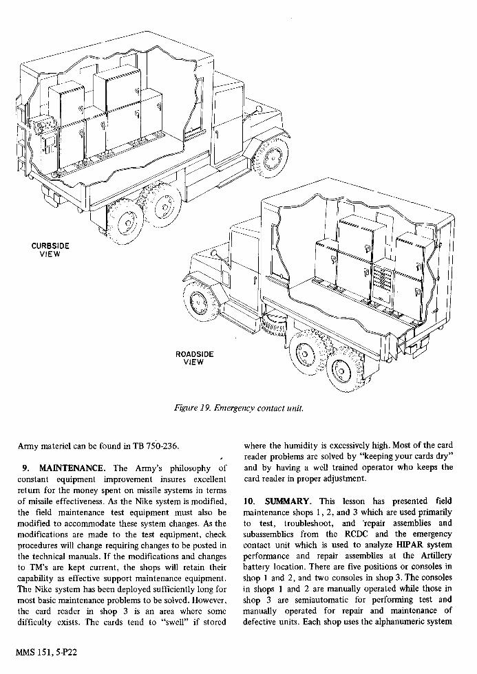
Figure 19. Emergency contact unit.
Army materiel can be found in TB 750-236.
9. MAINTENANCE. The Army’s philosophy of constant equipment improvement insures excellent return for the money spent on missile systems in terms of missile effectiveness. As the Nike system is modified, the field maintenance test equipment must also be modified to accommodate these system changes. As the modifications are made to the test equipment, check procedures will change requiring changes to be posted in the technical manuals. If the modifications and chariges to TM’s are kept current, the shops will retain their capability as effective support maintenance equipment. The Nike system has been deployed sufficiently long for most basic maintenance problems to be solved. However, the card reader in shop 3 is an area where some difficulty exists. The cards tend to “swell” if stored
where the humidity is excessively high. Most of the card reader problems are solved by “keeping your cards dry” and by having a well trained operator who keeps the card reader in proper adjustment.
10. SUMMARY. This lesson has presented field maintenance shops 1, 2, and 3 which are used primarily to test, troubleshoot, and ‘repair assemblies and subassemblies from the RCDC and the emergency contact unit which is used to analyze HIF’AR system performance and repair assemblies at the Artillery battery location. There are five positions or consoles in shop 1 and 2, and two consoles in shop 3. The consoles in shops 1 and 2 are manually operated while those in shop 3 are semiautomatic for performing test and manually operated for repair and maintenance of defective units. Each shop uses the alphanumeric system
MMS 151,5-P22

for locating stored test adapters and accessories used in performing test and maintenance on assemblies. Each console is capable of being used to test different assemblies or UUT’s and master TB 94900-250-35/1 is used to route the UUT to the correct console. When the UUT arrives at the correct console the operator also uses
the master TB to determine which manual, stored at the console, should be used to perform maintenance on the UUT. When the UUT is repaired it is returned to supply channels or returned to the Nike.Artillery battery from which it came.
MMS SUBCOURSE NUMBER 151, NIKE MISSILE AND TEST EQUIPMENT
EXERCISES FOR LESSON 5
1. After performing a voltage check on a relay assembly, at what panel in shop 1 is switching accomplished to change to a relay check?
A. A B. M c. P D. Z
2. Which is the first step in determining the location of a malfunction in a faulty chassis?
A. B. C. Visually inspect the UUT D. Measure the UUT parameters
Route to the proper console Connect the UUT to the console
3. At what location in the electrical test and maintenance table of position 1 is the receiver-gate generator stored?
A. A1 B. A2 C. B1 D. B2
4. Which test set is located at position 3 of electronic shop l ?
A. Servo test set AN/MPM48A B. Computer test set AN/MPM45 C. D. Radar test set AN/MPM-37A
Electrical power test set AN/MPM42
5 . Which electronic shop position is used to test computer assemblies?
6. In what portion of shop 3 are the programmed comparator limits compared with the measured parameters from the UUT’s?
A. Digital readout circuits B. Digital multimeter and counter C. Time stretcher D. Waveform analyzer-monitor
7. Which gives information concerning calibration requirements for test equipment associated with the improved Nike Hercules system?
A. TB 94900-250-35/1 B. TM 9-1400-250-34/2/2 C. TB750-236 D. TB9-131-2
8. Which consoles are located in e.-ctronic LOP 3?
A. 6 a n d 7 B. 4 a n d 5 C. 2 a n d 3 D. 1 ,2 ,and3
9. Which is NOT a functional group of the equipment mounted in shop 3?
A. GFE B. DAME C. SITE D. CPE
10. Which is one of the primary considerations for retaining the use of patch cards in electronic shop 3?
A. 1 B. 2 c. 4 D. 5
A. Simple B. Economical C. Automatic D. Fault free
MMS 151,5-P23
11 . In the absence of a pass indication on console 7, what action should be taken on part of the operator?
A. Perform troubleshooting procedures B. C. D. Perform the acceptance test
Tag the WT with the step failed Place the CPE into semiautomatic operation
12. What is a function of the console programming equipment in electronic shop 3?
A. Select and position switches B. Test theUUT C. Establish comparator limits D. Verify program card selection
13. A chassis with part number 9140754 arrives at a Nike direct support unit. To which electronic shop position should this chassis be sent to receive proper testing?
A. 1 B. 3 c. 4 D. 5
14. What chapter of TM 9-1400-250-34/3/2 should be used by the technician to make an acceptance test on part number 9 140767?
A. 21 B. 9 c. 5 D. 4
15. What was the primary purpose of automating the operation of electronic shop 3?
A. Increase test accuracy B. Decrease test time C. Increase reliability D. Decrease equipment cost
16. What is the maximum number of tube stages mounted on a minispec?
17. In which area are the connectors for intercon- nections between the UUT and console 6 located?
A. A1 B. A2 C. A3 D. A4
18. A UUT being tested at console 6 does NOT meet the comparator limits established by the program. If the operator successfully performs all the prescribed troubleshooting aids and finds all switches in the correct position, to what location is the malfunction isolated?
A. Console B. UUT C. Interconnecting cables D. Crossbar switch
19. Which class of information is NOT contained on the program cards for electronic shop 3?
A. Switch position B. Card select C. Endofcard D. UUTpassorfail
20. What is one maintenance problem associated with electronic shop 3?
A. Patch cards B. Crossbar switch C. Time interval test D. Card reader adjustments
21. The electrical program signals are generated by the card reader in shop 3 when the
A.
B. C. D.
picker knite puts the card into the feed rollers. card is clamped onto the drum. star wheels drop into the punched holes. microswitches drop into the punched holes.
22. Personnel holding which MOS should be dispatch- ed to the HPAR with the ECU?
A. 2 B. 3 c. 4 D. 5
A. 23N B. 23U c. 22L D. 22G
MMS 151,5-P24
23. Which establishes continuity with the verification circuits in the remote switching control at console 6?
A. Program card B. Patch cards C. Card reader D. Console programming equipment
24. In which alpha designated drawers of the electrical test and maintenance tables are the patch cards located?
A. Al ,A2andBl ,B2 B. Al ,A2andCl,C2 C. Bl ,B2andCl,C2 D. C1, C2 and D1, D2
25. Which is tested at position 2 of electronic shop l?
A. Relays B. Voltage regulators C. CRT indicators D. Communication assemblies
26. Which shop position is used to test a complete RF system?
A. ANIMPM43
C. ANIMPM48A D. AN/MPM47
B. AN/MPM-37A
27. What was added to the field maintenance test equipment to change it to an improved field maintenance system?
A. Emergency contact unit B. Electronic shop 1 C. Electronic shop 2 D. Electronic shop 3
28. What information is contained in the last two columns of a punched card of electronic shop 3 if the test is incomplete?
A. Card select B. Switch position C. Comparator limits D. Endof test
29. Which is used to determine the position at which a UUT is tested?
A. DAForm2407 B. TM 9-1400-250-34/'2/2
D. Chassis control number C. TB 94900-250-3511
30. What instructions are given by the acceptance test portion of the chapter in TM 9-1400-250-34/2/2 pertaining to part number .9140712?
A. Purpose of the test B. C.' Waveshapes to be observed D.
Procedures for connecting the UUT
Test layouts to be used
MMS 151,5-P25