
SUB-LEVEL OPEN STOPING: DESIGN OF THE O640, L651 AND …
77
SUB-LEVEL OPEN STOPING: DESIGN OF THE O640, L651 AND N659 SUB-LEVEL OPEN STOPES IN THE 3000 OREBODY OF THE MOUNT ISA COPPER MINES, QUEENSLAND, AUSTRALIA L. SLOANE Presented in partial fulfilment of the requirements for the degree: M.ENG (MINING ENGINEERING) IN THE FACULTY OF ENGINEERING DEPARTMENT OF MINING UNIVERSITY OF PRETORIA OCTOBER 2010 © University of Pretoria
Transcript of SUB-LEVEL OPEN STOPING: DESIGN OF THE O640, L651 AND …

SUB-LEVEL OPEN STOPING: DESIGN OF THE O640, L651 AND N659
SUB-LEVEL OPEN STOPES IN THE 3000 OREBODY OF THE MOUNT ISA
COPPER MINES, QUEENSLAND, AUSTRALIA
L. SLOANE
Presented in partial fulfilment of the requirements for the degree:
M.ENG (MINING ENGINEERING)
IN THE FACULTY OF ENGINEERING
DEPARTMENT OF MINING
UNIVERSITY OF PRETORIA
OCTOBER 2010
©© UUnniivveerrssiittyy ooff PPrreettoorriiaa

I hereby declare that this dissertation is my own unaided work. It is being
submitted for the degree M. Eng (Mining) at the University of Pretoria. This
work has not been submitted before for any other degree or examination at
another tertiary education institution.
Lomar Sloane
NAME OF AUTHOR

SYNOPSIS
Supervisor: Professor M.F. Handley
Department: Mining Engineering
University: University of Pretoria
Degree: M.Eng (Mining Engineering)
This dissertation will explore the process followed in the design of a sub-level open stope
(SLOS) by using examples of actual stopes scheduled to be in production between August
2006 and February 2007. The main objective is to give the reader an understanding into
sub-level open stoping and the design process followed. The objective here is to present a
design methodology applicable to sublevel open stoping, but also to then bridge the gap
between theory and practice by applying said methodology to an actual design example.
The design examples used in this dissertation is based on the O640, L651 and N659
stopes in the 3000 Orebody of Xstrata Copper Operation’s Mount Isa Mine, located in
North-West Queensland, Australia. The actual design reports as required by the mine are
attached in Annexure 1 through 3. Given the similarities of the designs, only O640 will be
analysed comprehensively within the main content of this report, with L651 and N659
discussed specifically insofar issues that were unique to these stopes. With the design of
O640, all aspects or design considerations as stipulated in the design process were
discussed and analysed so as to define the final stope shape. These design considerations
include:
• Faulting
• Grade Contours
• Existing Development
• Surrounding Fill masses
• Rock Mechanics
Once the final stope shape has been set, options regarding stope extraction will take place.
This is where the initial stope layout takes place and where the engineer looks at the

advantages and disadvantages of all the different options available in mining the stope. In
this phase, the most effective extraction option is decided upon. Once the engineer have
decided a final stope shape and extraction option, the stope will be analysed in further
detail referring to drilling, the amount of drawpoints, ventilation and other stoping
requirements. These are all defined as stope design features and are considered a general
summary of the stope design.
The design features phase is closely followed with all the safety considerations that have
been taken into account since the stope design started. Main concerns and stope specific
safety issues are discussed and possible solutions given. It is part of the work of the mine
planning engineer to anticipate all possible safety issues and make the production
department aware of what can be expected during the development, mining and filling
activities of every stope. At this stage the design of the stope nears completion. The
remainder of the design now goes into more detail and addresses the critical tasks that
from part of sub-level open stoping. These include:
• Reserves and Scheduling
• Development and Drilling
• Production and Firing (Blasting)
• Ventilation
• Services
• Filling
• Economic Analysis
Although all of the abovementioned have already been mentioned during the design
features phase, it is still required to give additional details so the different departments
involved have an accurate idea of what to expect, when to expect it and therefore be able to
sufficiently plan for it. It must be noted that it does happen that something may be
“discovered” during any stage of the final design, which may render the current design
undesirable. When this happens the stope must be re-designed until all issues have been
resolved or at the least have been managed appropriately. Even though this report does not

go into detail with the L651 and N659 designs, these designs are included as they bring to
light issues that may arise that are unique to individual stopes. L651 looks at how a design
drastically changes when ore not planned for is discovered. N659 looks at what happens
when a stope is the first to be mined in an area with inadequate infrastructure.
The main content of the dissertation discusses and explains the design procedure as it
would take place at Mount Isa Mines, but it is still quite difficult to follow logically. For this
reason a flowchart was included to give the reader a more comprehensive summary of the
design process.
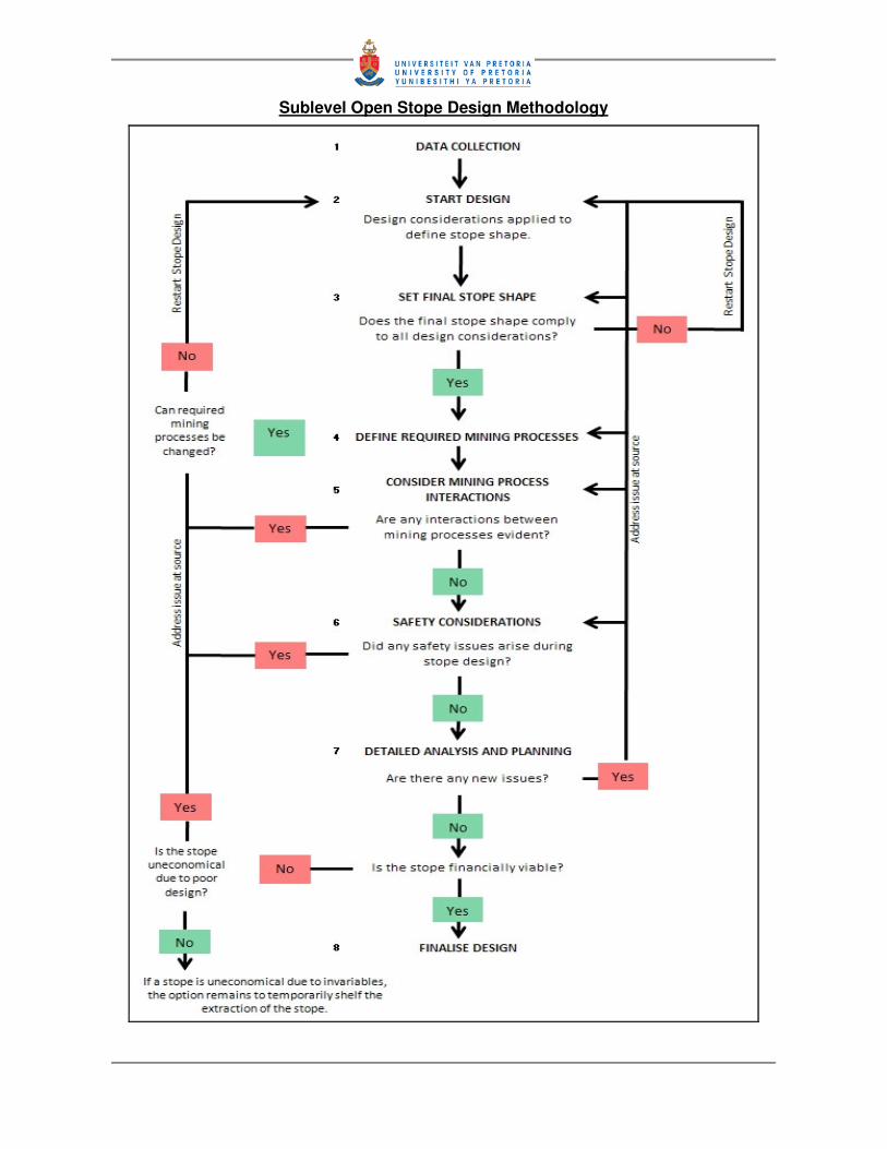
Sublevel Open Stope Design Methodology
TABLE OF CONTENTS
1. Introduction
1.1 Mine Background and General Information 1
1.2 Project Background and Literature Review 2
1.3 Design Requirements 7
2. Methodology 8
3. Sub-Level Open Stope Design
3.1 The Planning Process 9
3.2 O640 Final Design 12
3.2.1 Design Considerations
3.2.1.1 Faulting 13
3.2.1.2 Grade Contours 16
3.2.1.3 Existing Development 18
3.2.1.4 Surrounding Fillmasses 21
3.2.1.5 Rock Mechanics 23
3.2.2 Development and Drilling
3.2.2.1 Development Requirements 25
3.2.2.2 Rehabilitation Requirements 26

3.2.2.3 Drilling Requirements 27
3.2.3 Production and Firing
3.2.3.1 Mucking 34
3.2.3.2 Firing Sequence 35
3.2.4 Ventilation 37
3.2.5 Services 40
3.2.6 Filling 40
3.2.7 Extraction Options 41
3.2.8 Design Features 43
3.2.9 Safety Considerations
3.2.9.1 Remote Mucking 44
3.2.9.2 Optechs 45
3.2.9.3 Bulkheads 45
3.2.10 Reserves and Scheduling
3.2.10.1 Reserves 46
3.2.10.2 Scheduling 48
3.2.11 Economic Analysis 49

3.2.12 Stope Physical Data Summary 50
3.3 Considering Other Design Issues
3.3.1 The L651 Stope 52
3.3.2 The N659 Stope 56
4. Conclusions 61
5. References 62
ANNEXURE 1
ANNEXURE 2
ANNEXURE 3

NOMENCLATURE
1. ANFO Ammonium Nitrate Fuel-Oil (explosives)
2. BC Basement Contact
3. BCF Basement Contact Fault
4. BCZ Basement Contact Zone
5. CHF Cemented Hydraulic Fill
6. CO Cut-off
7. COLHW Cut-off Long Hole Winze
8. Cu Copper
9. DDR Drill drive
10. DH Downhole
11. DPT Drawpoint
12. DSS Mine electronic database
13. FAR Fresh air raise
14. FD Final Design
15. FPAC Fill pass access
16. FWDR Footwall drive
17. LOM Life of Mine
18. MR Main ring
19. Mucking Broadly refers to load haul dump operations
20. NDR North drive
21. NEDR North-east drive
22. NEXC North-east crosscut
23. NWDR North-west drive
24. NWXC North-west crosscut
25. OP Ore pass
26. PD Preliminary Design

27. RAR Return air raise
28. SEXC South-east crosscut
29. SLOS Sub-Level Open Stope
30. SWXC South-west crosscut
31. TUC Trough undercut
32. UBC Upper Basement Contact
33. UH Uphole
34. XC Crosscut

LIST OF FIGURES
Figure 1 Location of Mount Isa Mines 1
Figure 2 O640 Stope location 12
Figure 3 O640 Faulting (section looking north) 14
Figure 4 O640 Faulting (section looking south) 15
Figure 5 O640 Grade contours (section looking north-west) 17
Figure 6 O640 Existing development (section looking south-west) 19
Figure 7 25A Sublevel required development 19
Figure 8 26B Sublevel required development 20
Figure 9 27C Sublevel required development 20
Figure 10 27L Sublevel required development 21
Figure 11 O640 Surrounding fill masses 22
Figure 12 O640 Reduced crown stress (after Esterhuizen, 2005) 24
Figure 13 O640 Cut-off and COLHW layout 31
Figure 14 MR02 Boundary holes 32
Figure 15 MR06 Holes 32
Figure 16 Long section 45°°°° north-east 33
Figure 17 O640 Mucking and tipping in P64 OP 34
Figure 18 O640 Firing sequence 36
Figure 19 25A Ventilation circuit 38
Figure 20 26B Ventilation circuit 38
Figure 21 27C Ventilation circuit 39
Figure 22 27L Ventilation circuit 39
Figure 23 L651 Preliminary design 52
Figure 24 L651 Preliminary design with 2005 block model 53
Figure 25 L651 Final design with additional required development 54
Figure 26 N659 Final design with no drawpoint level access 56

Figure 27 N659 showing surrounding infrastructure 58
Figure 28 Final design for 28B sublevel 59

LIST OF TABLES
Table 1 Horizontal development 26
Table 2 Rehabilitation requirements 27
Table 3 Production drilling 29
Table 4 Ring design parameters 30
Table 5 Development, drilling and ring firing requirements 37
Table 6 Mucking ventilation requirements 37
Table 7 O640 Stope design tonnes 47
Table 8 Financial results for O640 49

Lomar Sloane Page 1
INTRODUCTION
1.1 MINE BACKGROUND AND GENERAL INFORMATION
Mount Isa Mines is a world class copper, silver, lead and zinc orebody located in the north-
west of Queensland. The location of the mine is shown in Figure 1. Lead mineralization at
this location was discovered in 1923 by John Campbell Miles with diamond drillholes only
intersecting and indicating copper deposits in the early 1930’s. Not much exploration or
exploitation of the copper orebody was done until the early years of the Second World War
when the demand for copper was high. The first copper was mined during this time. From
here on the mining and further exploration of the orebody took off and the Mount Isa Mines
were formed. Different orebodies were discovered and subsequently mined, but it wasn’t
until 1962 that the 3000 Orebody was discovered and five ears later, 1967, the 3500
Orebody was discovered. Even though these orebodies were discovered during the 1960’s,
production from the first stope in the 3000 Orebody was only started in March 1993. The
first stope in the 3500 Orebody only started in December 1996. In 1998 the initial name for
the two Orebodies, known as Deep Copper, was changed to the Enterprise Mine.
Figure 1: Location of the Mount Isa Mines
Mount Isa Mines

Lomar Sloane Page 2
1.2 PROJECT BACKGROUND AND LITERATURE REVIEW
All stopes go through various design stages before actual work starts underground. These
include the conceptual design phase, the preliminary design phase and lastly the final
design phase. Conceptual and preliminary design phases are done years in advance,
based on certain indicators such as copper price and relative copper cut-off grades at that
time. The final design is done approximately 6 months to a year before planned
development for a stope begins and is therefore much more representative of the current
situation than previous designs.
The O640 stope was the next stope within the 3000 orebody that reached final design
phase. This stope was scheduled to start production in August 2006. The opportunity was
taken by the author to shed light on the process of sub-level open stope (SLOS) design as
it is practically done in the industry. The main focus of this document is based on the design
of the O640 stope, including all relevant design parameters and processes as required by
the Mount Isa Mines. Two other stope designs, the L651 and N659 stope designs are also
given due consideration in this document as it highlights other design considerations not
found during the design of the O640 stope. These will focus on stope specific issues, which
will explain the different challenges that are encountered when designing sub-level open
stopes.
The author proposes a design procedure/methodology, which forms the basis of the stope
designs. The design methodology proposed is mine and application specific, in this case
sub-level open stoping. A major aspect of this dissertation, however, is also bridging the
gap between theory (proposed design methodology) and actual application, where the
design methodology is applied by means of an example stope design.
Design methodologies are by no means a new concept nor have they only cropped up over
the last few years. Design methodologies have come a long way and have also evolved to
encompass the current industry and current work ethics. The design procedure presented
in this dissertation reflects the design process as it takes place at the Mount Isa Mines.
Correlations are evident when compared to well published design processes such as given
by Bieniawski (1992), but here the design process application is mine(s) specific.
Bieniawski (1992) proposed a 10 step design process, which although originally intended

Lomar Sloane Page 3
for use and application in the rock engineering field, is very much applicable and useful to
other engineering design fields. These ten steps are:
1. Statement of the problem (performance objectives)
2. Functional requirements and constraints (design variables and design issues)
3. Collection of information
4. Concept formulation
5. Analysis of solution components
6. Synthesis and specifications for alternative solutions
7. Evaluation
8. Optimization
9. Recommendation
10. Implementation.
The process as used by Mount Isa engineers are basically an adjusted and site specific
version, which has been refined over the years, of the methodology proposed by Bieniawski
(1992). Ilbury and Sunter (2005) more recently proposed an “updated” way of looking at the
planning process. Where Bieniawski (1992) is a linear and logical approach to design,
Ilbury and Sunter (2005) is circular. Stacey (2009) does a remarkable and interesting
comparison between the different approaches to planning and design as it is applicable to
the mining industry. The available literature confirmed the validity of the design
methodology as proposed and applied in this dissertation.
Design methodologies are great tools to arm the engineer with the correct approach to
design. It basically directs the engineer as to how he/she needs to think to accomplish a
task. Herein also lies the issue. It does not show the engineer how to design anything. Be it
a stope, a mine or even just a single drive. It directs the thought process, but not how to
actually do it.

Lomar Sloane Page 4
There is lots of literature available on design principles and design concepts. The website
OneMine.org is a veritable vault of mining and mining related papers and documents. This
site contains over 54,000 mining related papers. A search of papers containing the phrase
‘designs methods’ yielded 16,000 documents. This is excessive and given the nature and
aim of this dissertation, the author narrowed the search to ‘sublevel open stope design’ and
related articles. This search yielded 234 papers with regards to the design of sublevel open
stopes. Many of these papers refer to and are included in the larger colloquiums such as
the SME Mining Engineering Handbook (Cummins et al., 1992), Design and Operation of
Caving and Sublevel Stoping Mines (Steward, 1981), and others. These books were highly
valuable in starting to narrow down how to design a sub level open stope. That is,
ultimately, the objective of this dissertation.
The main issue the author experienced with most of the well known and published
literatures was that most of it is either focussing on the larger issues regarding sub level
open stoping, i.e., how to design a sub level open stope mine and its associated governing
factors (This is also the particular focus of Hustralid et al. (1982), Hustralid and Bullock
(2001), Gertsch et al. (1998) and Steward (1981)), or much more technical and stope
specific issues relating to sublevel open stopes such as rock mechanics and associated
geotechnical issues (Pakalnis, 1986).
Hustralid et al. (1982) is fairly comprehensive with regards to all aspect pertaining to sub
level stoping. It covers factors that influences and requires due consideration when
designing sub level stopes. As mentioned earlier, however, this is also in the form of a
colloquium. Hustralid et al. (1982) briefly describes sublevel open stopes in general and the
remainder of the contained literature are examples of stopes at mines throughout the world
and the uniqueness pertaining to each of the mines. This gives the reader a broad
understanding of the concept of sublevel stoping. Hustralid et al. (1982) does not, however,
contain any reference to design methodologies or design processes. Hustralid et al. (1982)
mainly focus on the technical/engineering considerations of SLOS mine design.
This is almost exactly the same focus as pertained in Cummins et al. (1992), the SME
Mining Engineering Handbook. Pakalnis (1986) on the other hand approaches SLOS
design differently than Hustralid et al. (1982) and Cummins et al. (1992). Here is an
example of SLOS design, but it is rock mechanics orientated and focuses on designing a
SLOS based on rock mechanics principles. Although this forms an important part of all

Lomar Sloane Page 5
SLOS designs, there are other critical parts of the design process that is not given due
consideration here. The contained works of Pakalnis (1986) is interesting as it provides
insight into SLOS design at the Ruttan Mine in Canada, but it does tend to suggest that this
is what SLOS design would be like if done by rock mechanics.
It is evident that there is no shortage of literature on sublevel open stopes. In fact, it seems
every major SLOS mine in the world is represented by a published paper. In some cases
there are multiple papers. Steward (1981), another colloquium of papers, contains works on
a SLOS mine in Finland. This is another generic paper on SLOS’s; however, there is a
more technical view on the actual requirements of individual SLOS’s. The information here
is considered closer to what the author aims with regards to the design of a sublevel open
stope.
Literature was found to be available on generic design methodologies, sublevel open stope
mine design concepts and mine layouts, highly technical papers dealing with specific
sublevel stoping issues and so on. The author, however, was specifically interested in what
literature is available that deals with the actual design of an open stope. Only two papers
were found that deals with this subject directly.
Villaescusa (2004) attempts to quantify the performance of sublevel open stopes via the
design process. He describes design methodology applicable for the design of a SLOS, the
finer designs points, the stope extraction sequence and finally the reconciliation of actual
vs. planned by means of cavity monitoring. A major focus of this paper is that the design
process should include for reconciliation of stopes (feedback) once it has been mined. This
is in order to improve future stope designs. Although the focus of Villaescusa (2004) is not
specifically how to design sublevel open stopes, the information contained largely covers
the methodology of how to design an individual sublevel open stope. This is very close to
the aim of this dissertation, where theory is presented and practically applied by means of a
design example.
Hustralid and Bullock (2001) contains a paper by Soma Uggalla, which discusses the
design and planning practice as it takes place at the Olympic Dam Mine in South Australia.
The aspects covered in this paper basically cover the aspects considered in the design
example of this dissertation. In other words, there is a very strong similarity between how
sub level open stopes are designed at Mount Isa Mines and the Olympic Dam Mine. Again,

Lomar Sloane Page 6
however, this paper is limited to theoretical considerations and there is no example of how
a design is done in practice.
It became evident that there is very little published with regards to actual sublevel open
stope design examples. Generic design methodologies such as given by Bieniawski (1992)
and even application and mining method specific design methodologies such as
Villaescusa (2004) are available, but the author could not find any literature where theory is
bridged and practically applied by means of a design example. Perhaps this is because it
may be considered an extremely mine or application specific thing to do.
This dissertation, therefore, is considered something of a novelty in that it proposes a
design methodology for the design of sublevel open stopes and then also explains the
application of said design methodology by means of a design example. Neither the design
methodology nor the design of a sublevel open stope is a new concept. In fact, most likely
hundreds if not thousands of mining engineers have in their careers designed a sublevel
open stope. None, however, seems to have attempted to share this knowledge. That is
done in subsequent chapters of this dissertation.

Lomar Sloane Page 7
1.3 DESIGN REQUIREMENTS
Design the O640, L651 and N659 sub-level open stopes within the 3000 orebody so that it
complies with all relevant mine codes of practice and government regulations. The final
designs for these stopes must prove the stopes able to be mined effectively, profitably and
above all else safely.
Once the designs are completed it will be scrutinized and approved by all parties involved in
the design; development, drilling, firing (blasting) and filling of the stopes.
The O640 design was completed in mid November 2005 and the sign-off sheet (copy) is
attached in Annexure 1. L651 and N659 are only scheduled to produce much later and
therefore no sign-off sheets are presented.
In order to make a valid and financially viable SLOS design, certain key aspects need to be
identified and established throughout the contents of this report. The principle of these
includes:
• Designing a final stope shape
• Designing the required development for stope access
• Designing a drill layout for stope firing (blasting)
• Determining an effective firing (blasting) sequence for the stope
• Designing and determining other stope requirements including mucking (loading),
ventilation, stope filling, and other considerations.
• This design examples will address and explain all the above mentioned aspects in an
effort to design a sub-level open stope that will be profitable, but most importantly, will
be safe to mine.

Lomar Sloane Page 8
2. METHODOLOGY
The final design was performed in a manner which closely represents the process as it
would take place underground once mining activities relating to that stope starts. Initially the
design looks at all factors governing the final stope shape. After a stope shape has been
set, the design will continue with the development design pertaining to accessing the stope,
followed by drilling, firing, mucking, ventilation, filling and the stope economic evaluation,
once all data have been gathered. Should serious issues be encountered during any stage
of the design, certain alterations to the stope design may be required to compensate for this
and changes may be required as far back as the initial stope shape defining stage. The
whole design procedure is in essence iterative, with changes continuously taking place
during all stages of the design. The followed methodology closely resembles that of
Villaescusa (2004) and even broader ones as postulated by Bieniawski (1992).
Once the final design is complete, mining activities will commence underground. The
setting up of the stope may take several months and other stopes in the area may be at
some other stage in the mining process be it firing (blasting), filling, etc., but any one of
these can over the time periods involved cause the final design to become unsuitable. This
does not constitute a re-design, but the planning engineer must continuously inspect the
progress of designed stopes underground and monitor possible influences to the final
design and rectify these changes on the go. As a contingency, the design process for sub-
level open stopes have been split, with the final design being the first and major design
stage and a ring design stage following the final design once all development for the stope
is complete and drilling is about to commence.
The ring design is not discussed here, but in short is when the final drilling plans are done
(based on the final design drill layouts), but compensating for any deviations from the
original final design. It must be noted that at this stage geology and grade estimates would
have been updated, based on development done around and though the stope boundaries,
so the planning engineer will now have a better understanding of how the stope will
perform. In almost all cases only minor changes to the final design will take place to
optimise stope extraction.

Lomar Sloane Page 9
3. SUB-LEVEL OPEN STOPE DESIGN
3.1 THE PLANNING PROCESS
The mine planning engineer lies at the heart of all design work done. Given the nature and
most likely the sheer size and complexity of even some smaller mining operations, the
planning engineer needs to do his/her work in an orderly and pre-determined fashion.
Because of this it is necessary to follow, as closely as possible, a design methodology as
given on the next page. This ensures that all aspects of the design process and area
responsibilities that fall under the care of the planning engineer are thoroughly investigated.
In no way does this mean that the duties of the planning engineer are either monotonous or
straightforward. Every section of the mine and every stope for that matter will encompass
its own unique set of challenges and features, which makes every single stope design
unique and different to the next. The methodology used by the planning engineer to design
stopes and see them through to reconciliation is called the planning process.
The planning process encompasses the whole design philosophy of a sub-level open stope
and is not confined to the design of a stope only. The planning process describes the initial
stope design to final stope design continuing though to stope production, stope filling and
finally stope reconciliation. Planning plays a major role in each of these areas.
The planning of any given stope will always follow a set design process. First of these are
the conceptual design, followed by the preliminary design and then the final design. These
are all stages of design where no actual underground work has been done. Each of these
stages plays an important part in the overall mine plan. For instance, the conceptual design
gives valuable information that helps with long term mine planning (LOM planning). The
conceptual design is largely based on assumptions and estimates with relatively limited
measurables.
The preliminary design is done in much more detail than the conceptual design and
information and figures generated here are used in the next year’s annual mine budget. At
this stage nearby stopes and development drives in the area of the planned stope have
already been mined, which gives a much better idea of the surrounding area. The
preliminary design therefore entails less assumptions and estimates than the conceptual
design.

Lomar Sloane Page 10
Sublevel Open Stope Design Methodology

Lomar Sloane Page 11
The final design is the last phase of design work done before physical mining activities will
start on the stope. This does not mean that no development for the stope has been done. In
many cases development for one stope also serves as development for another stope in
order to reduce the amount of overall development. At this stage the confidence in area
geology and geotechnics are very high given the amount of mining already done. At the
final design phase confidence in measurements and facts run close to the 90% mark.
In no way is any design the work of one person. The planning engineer will do the actual
design, but will liaise with several other professionals during this time. Three fields of
expertise work closely together to produce the stope final design. These include the
geologist, the rock mechanics engineer and the mine surveyor. They are the primary
information sources and no design is possible before information regarding the area has
been gathered from them. This report will therefore include extractions from geology and
rock mechanics notes prepared specifically for the final design of O640 in order to explain
reasons why certain decisions were made.
To do a sub-level open stope design, the following information is required:
• The preliminary stope design
• Geological data
o Diamond drill hole data and stratigraphy
o Block models (grade indicator)
o Faulting
• Survey data
• Relevant mining standards and regulations
• Key indicators – Metal prices, development unit costs, equipment scheduling and
availability, and others.
Once all these are known to the highest degree of certainty, the final design of the stope
can begin

Lomar Sloane Page 12
3.2 O640 FINAL DESIGN
Sub-level open stoping is a complicated procedure with many deviations from the generic
examples taught in universities around the world. For this reason a design example is used
to explain the design procedure as it applies to Mount Isa Mines and the sub-level open
stoping unique to this mine. All that follows is extracted from the actual O640 stope final
design done by the author as well as explanations as to how and why it is done.
“O640 stope is a 1-SLOS stope located centrally within the 3000 orebody. This stope is
currently scheduled for production in August 2006.” (Quoted from Sloane, 2006)
The “O” in the stope name is derived from dividing of longitudinal lines (eastings) into
alphabetical sections and the “640” gives the mean location of the stope in relation to
latitudinal lines (northings). This is illustrated in Figure 2. Figure 2 also shows current active
stopes, filled stopes and stopes yet to be mined.
Figure 2: O640 stope location
Active stopes, which are indicated by the red border around the stope shape, shows that
these stopes are in some stage of mining. Filled stopes are completely coloured. The colour
of the block indicates the type of backfill used to fill the stope. Different types of backfill
used at Mount Isa Mines includes cemented hydraulic fill (CHF), cemented mullock fill
(CMF), aggregate and paste fill. Paste was the latest addition to 3000 orebody and it is
planned to fill all future stopes with paste only. CHF will be used as a back-up fill system.
O640 STOPE LOCATION
CHF filled stope
Aggregate filled stope
CMF filled stope
Paste filled stope
Lomar Sloane Page 13
The scheduling engineers at the mine determine the time when a stope is up for production
and the planning engineer does all designs accordingly.
3.2.1 DESIGN CONSIDERATIONS
“Several factors were considered in this design and will be discussed under separate
headings as follows: Faulting, Grade contours, Existing Development, Surrounding
Fillmasses and Rock Mechanics.” (Quoted from Sloane, 2006)
3.2.1.1 FAULTING
“The 30N N62 Dark Green Fault intersects the crown of the stope at 6400mN. This is an
area in which crown overbreak is a possibility and is discussed in more detail in Section
3.2.1.5. O640 is also intersected by the 30N Q61 Dark Blue Fault roughly through the
middle of the stope at 2120mRL towards the bottom and will intersect the drawpoints on
27L.
The upper basement contact (UBC) forms the western boundary of O640. Some issues
with dilution are possible where the basement contact dips steeply, particularly where
intersected by the 30N N62 and 30N Q61 Faults. The basement contact has in the past
caused stability problems drawpoints and stope cut-offs, hence adequate measures must
be taken once development enters this zone.” (Quoted from Sloane, 2006)
The geologist supplies the planning engineer with the relevant geological information
needed to start the stope design with. Two critical components are required from the
geologist. These are the faults that intersect the stope and the grade contours (Section
3.2.1.2) that lies within the stope. Faulting in the stope gives the engineer a very good
indication as to how the stope will perform in terms of overbreaking and possible failure
areas once mining starts. It will be noted that in this case there are three major fault
systems that run through the stope. The location of these faults in relation to the stope is
shown in Figures 3 and 4.
Note the bottom portion of the stope in Figure 3. This area is where the initial stope shape
(shape from preliminary design) intersects the basement contact fault zone (BC in short).
The BC basically determines the stope’s lower boundary as mineralization abruptly ends on

Lomar Sloane Page 14
this contact. This contact (BC) is in essence a large shear zone, which denotes the one
major boundary of the total mine reserve and no copper is found beyond this zone.
Ground conditions in the BC zone are usually poor and require significant support to keep
the area operational and safe for the duration of the stope life. Generally stopes are
planned to stop all development once the BC is intersected, but in some cases it is
necessary to go through or into the BC in order to reach all mineralization above this zone.
One characteristic of the BC is that mineralization tends to be at its highest just above this
zone, hence the occasional need to intersect the contact.
Figure 3: O640 Faulting (Section looking north)
30N N62 Dark Green Fault – Possible crown stability issues because of fault
30N Q61 Dark Blue Fault – Possible south eastern wall stability issues because of fault
Upper Basement Contact – Intersection and close proximity to stope drawpoints may cause stability issues
Upper Basement Contact
Lomar Sloane Page 15
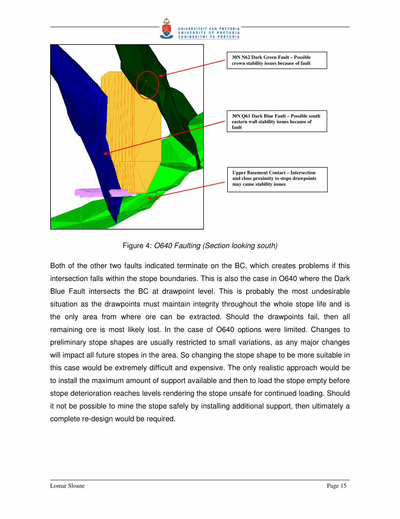
Figure 4: O640 Faulting (Section looking south)
Both of the other two faults indicated terminate on the BC, which creates problems if this
intersection falls within the stope boundaries. This is also the case in O640 where the Dark
Blue Fault intersects the BC at drawpoint level. This is probably the most undesirable
situation as the drawpoints must maintain integrity throughout the whole stope life and is
the only area from where ore can be extracted. Should the drawpoints fail, then all
remaining ore is most likely lost. In the case of O640 options were limited. Changes to
preliminary stope shapes are usually restricted to small variations, as any major changes
will impact all future stopes in the area. So changing the stope shape to be more suitable in
this case would be extremely difficult and expensive. The only realistic approach would be
to install the maximum amount of support available and then to load the stope empty before
stope deterioration reaches levels rendering the stope unsafe for continued loading. Should
it not be possible to mine the stope safely by installing additional support, then ultimately a
complete re-design would be required.
30N N62 Dark Green Fault – Possible crown stability issues because of fault
Upper Basement Contact – Intersection and close proximity to stope drawpoints may cause stability issues
30N Q61 Dark Blue Fault – Possible south eastern wall stability issues because of fault

Lomar Sloane Page 16
Figure 4 highlights another area of concern. This area is indicated in the figure where the
Dark Green Fault intersects the crown of the stope. Stope crowns and floors (also called
footprints) are designed within the cut-off grade contour (2% Cu within 3000 orebody).
Overbreak usually causes areas outside these contours to fall in, hence causing grade
dilution. Even though overbreak usually contains some copper, it still impacts negatively on
overall stope grade and increases overall stope unit costs. Failure towards the sides of the
stope is usually not so much of a problem as this most likely still fall within high grade
areas, but this is likely then failure into a future stope’s boundaries. This will affect the
design and profitability of said stope.
When designing a stope it is wise to review the performance of other similar stopes in the
surrounding area. The 3000 orebody is known to have good competent ground despite the
presence of faults. Overbreak at fault intersections do occur, but is usually much less than
in other parts of the mine. Given the average stope size, it will also mean that O640 can be
mined in relatively little time, so stope deterioration should not be a problem. The decision
was made to try and leave the stope shape to minimize the impact it would have on future
stopes should there be significant shape changes. Where faults intersect drives and the
crown of the stope, it would be more prudent to install ground control systems to try and
maintain stope integrity for the durations of the stope life.
3.2.1.2 GRADE CONTOURS
“The stope lies almost entirely within the 2.0% kriged Cu contour. Approximately 30% of the
stope lies within the 5.0% kriged Cu contour with a small 8.0% pod close to the top of the
stope. The Ore Reserve/ Mineral Resource Estimate (2003-2004) for O640 were 230,863t
@ 4.62%Cu. The 2005 Block Model based on the O640 preliminary design shape
calculated 225,634t @ 4.79%Cu. The latest calculation, based on the new final design
shape in which the north-western boundary was moved 1m in, yields a design tonnage for
O640 at 211,611t @ 4.77%Cu. The Geology Note can be seen in Annexure 1, Appendix 1.”
(Quoted from Sloane, 2006)

Lomar Sloane Page 17
Figure 5: O640 Grade Contours (Section looking North-west)
Stope shapes and sizes are controlled by numerous factors. It would be easier to have big
stopes. This would mean less development for more tonnes. Geology and rock mechanics
factors, however, largely determine the size and shape of stopes in order to minimize
failures, ground movement and increase overall safe working conditions. One aspect
remains universal in all SLOS designs, all of them are designed to minimise the amount of
waste taken with ore. In many cases small areas of waste may be included for some
reason, but usually stopes are designed to fall within the cut-off grade for that area. In the
case of the 3000 orebody, the cut-off grade is 2% Cu content. This is illustrated in Figure 5.
The red contour shows the 5%Cu contour, the green contour the 2%Cu contour, the blue
one the 1.7%Cu contour and the light blue contour the 0.7%Cu contour. Notice that al
contours terminate upon intersection with the basement contact. No grade occurs below
this contact.
O640 Stope Outline
RED: 5%Cu Contour
BLUE: 1.7%Cu Contour
GREEN: 2.0%Cu Contour
O638 Mined Out Stope Contour
LIGHT BLUE: 0.7%Cu Contour
P643 Future Stope Outline
91m
Basement Contact

Lomar Sloane Page 18
3.2.1.3 EXISTING DEVELOPMENT
“O640 requires development and/or rehabilitation on sublevels 25A, 26B, 27C and 27L.
Primary development locations and rehab required to mine this stope are largely influenced
by existing headings on the mentioned four sublevels. The O640 FPAC and top exhaust on
25A was governed by the existing headings R63 NDR and Q64 SWXC. The stope
boundary on 26B is defined by the existing M65 SEDR, which also influenced the
placement of the CO from this drive (O640 CO). The P63 NDR on 27C defines the north-
eastern boundary of O640 and here the existing O638 DPT1 and O638 DPT2 determines
the amount of fill mining required as well as the placement of the CO drive on 26B so as to
ensure we get a favourable CO position. The required mining on 27L, which is the DPT
level for O640, is governed by the existing P64 NDR and primary development is required
here in order to reach the stope position.” (Quoted from Sloane, 2006)
Mount Isa Mines encompass a vast amount of horizontal development to access all
orebodies. Levels are denoted by the numerical value and sub-levels are denoted by the
alphabetical denotation. It is basically used to describe a depth below surface to within 10m
of the actual depth of the development. Stope shapes are mainly determined by ore reserve
shapes and rock mechanic aspects as mentioned earlier. A development layout is then
decided upon to access all areas of the orebodies. Because the development for one stope
is likely to serve another stope or even several stopes, the chances are that the existing
development for one stope will likely influence the effective mining of another, hence
profitability. Care needs to be taken for this reason when any development designs are
done. It is of no use to profitably mine one stope, but to lose another in the process. Figure
6 shows the existing development in relation to O640. These sub-levels will serve as the
platform for all access development to reach O640.
Note that on 26B and 27C sub-levels development are already present within the stope
boundaries. 27L does not pass through the stope boundary but behind the stope as shown
in Figure 6. This will be crucial in designing where other development is required and how
and where the stope will be drilled from. Figure 7 through 10 shows plan views of the sub-
level used in the O640 design. It shows the existing development as well as new
development (design) that will be needed in accessing and mining O640 stope.

Lomar Sloane Page 19
Figure 6: O640 Stope Existing Development (Section looking South-west)
Figure 7: 25A Sublevel required development
25A
26B
27L
27C
25A 3000 OB Fill Horizon
26B – Existing development within stope boundaries
27C – Existing development within stope boundaries
27L – No stope access. Development design required for drawpoint access.
Blue and yellow drives are existing development. Required O640 development indicated – O640 Fill Pass Access (FPAC)

Lomar Sloane Page 20
Figure 8: 26B Sublevel required development
Figure 9: 27C Sublevel required development
Blue drives are existing development. Required O640 development indicated – O640 Cut-off Access (CO)
Blue drives are existing development. No new development required. “FM” hashed area indicates required fill mining.

Lomar Sloane Page 21
Figure 10: 27L Sublevel required development
3.2.1.4 SURROUNDING FILLMASSES
“O640 is a 1-SLOS and will therefore only expose one fillmass. This referring to the O638
fillmass, which is a 100% cemented hydraulic fill (CHF) fillmass. Both O636 and M646,
which are similar stopes to O640, have exposed CHF fillmasses and very little fill dilution
was encountered in these instances. Confidence is therefore high that the O638 fillmass
should remain intact with the taking of O640. Possible corner exposures exist with O636
and N640 stopes, but given the way that CHF fillmasses behave in general in this area, no
problems in this regard are expected. The exposure area of O638 lies between 26B and
27C sublevels.” (Quoted from Sloane, 2006)
It is very important to know where the surrounding fillmasses are. One would imagine that
this is a given, however, it does quite often happen that stopes are not fully filled, filled
volumes compared to calculated volumes differ and stope under-or-overbreaking can cause
that fill masses are in positions other than initially thought. A detailed investigation into fill
levels of surrounding stopes as well as fill type of the surrounding stope is required before a
Blue drives are existing development. Development to access stope draw area indicated within circle. Red lines over drive designs are known as “stops”. This is used to control timing of development. The “SUGC stop” means stop under geological control. The geologist will stop the drive development if the basement is intersected either sooner or later than planned.

Lomar Sloane Page 22
stope can be designed. The height and type of the fill mass to be exposed determines how
close and what type of explosive is needed for firing close to filled stopes. When it is
believed that the integrity of a fill mass is compromised, a pillar between stopes may be
required, which means a possible alteration of stope shape and size and therefore a loss of
mineable ore. Figure 11 shows the position of O638 fill mass in relation to the planned
O640 as well as other fillmasses in the surrounding area. O640 will only expose O638 and
exposures relating to other stopes resulted in no to very little fillmass failure, so confidence
in the safe exposure of O638 is high.
Figure 11: O640 Surrounding fill masses
N640
N643
P634
O636
O638
Paste filled stope
Cemented hydraulic filled stopes
N

Lomar Sloane Page 23
3.2.1.5 ROCK MECHANICS
“O640 crown is approximately 13m above 26B sublevel and the extraction level on 27L.
Access to O640 is on 3 levels, namely 26B, 27C and 27L. An overall reduction in crown
stress is expected due to the stope geometry forming an “inverted wedge.” This could lead
to crown overbreak due to the presence of the 30N N62 fault. This overbreak is expected to
be minor. The drawpoints will be highly stressed and will require deep reinforcement and
possibly shotcrete to limit stress induced ground control issues. In general, no major issues
are expected for O640 stope.” (After Esterhuizen, 2005)
The Rock Mechanics Note can be seen in Annexure 1, Appendix 2.
This is one of the more important aspects relating to stope final design. Whole stopes have
been lost because of failure to recognise potential ground movements, induced stresses
and other rock mechanics issues. The rock mechanics engineer is responsible for three
major components of the stope’s design.
1. Overbreak prediction – This allows the planning engineer to either redesign or proceed
with the design as is. Operations also need to know the amount of overbreak so as to
schedule and budget for additional lower grade tons. These predictions also may
anticipate major failures, which could goaf or self mine between levels, destroying mine
infrastructure and in some cases prevent major and possibly fatal air blasts.
2. Stress analysis – This helps the planning engineer to decide how and where to access
the stope from as well as what support is recommended by the rock mechanics
engineer.
3. Firing Sequence – The planning engineer with consultation by the rock mechanics
engineer will sequence stope firings in such a manner to “place” mining induced
stresses or to control and minimise damage from stresses to the stope itself and
surrounding stopes and area development.
In the case of O640 two major issues regarding rock mechanics were highlighted. These
are the possibility of “inverted wedge” crown failure and excessive stresses around the
stope drawpoints.

Lomar Sloane Page 24
O640 Crown – The crown of the stope was analysed looking at three aspects. The first
included a Map3D analysis of stresses around the O640 and O638 crowns. Mining of O640
will induce reduced crown stresses as an inverted wedge is formed between the two
stopes. Failure may occur as a result of this.
Figure 12: O640 Reduced crown stress (After Esterhuizen, 2005)
The second analysis consists of an empirical method known as the Matthews Stability
Graph. This assesses the stability of stope spans. According to the analysis the stope
crown falls within the transition zone (leaning towards the stable zone). This indicates
failure may take place given current design geometries.
The third analysis looked at the overbreak potential, where the “inverted wedge”
supposedly does fail. It is then estimated to where this failure my take place. This failure is
then looked at to see whether it holds any safety concerns, will impact other openings or
mine infrastructure and what tonnes and grade this failure contains. A decision is then
made as to how this potential failure will be regarded. In the case of O640 it was decided to
continue with the design as it is, because the potential failure is more than likely to be less

Lomar Sloane Page 25
than modelled (historic underbreak of other stope crowns in this area) and in the event that
failure does take place, it holds no safety concern and still carries enough grade as to have
no or little economic impact on the stope.
O640 Drawpoints – An analysis is required on all stope drawpoints (DPT’s) because this is
the only way that stopes can be mucked (loaded). Should the drawpoints fail, then the
stope is most likely lost. In the case of O640, it was determined that there will be a large
increase in stress around the drawpoints which will manifest itself as spalling and rock
noise. Based on this analysis the rock mechanics suggested a support pattern which will be
suited for the stope for the duration of its life. This support suggestion is then approved by
the relevant managers and given to the operations department to implement.
3.2.2 DEVELOPMENT AND DRILLING
Every final design is approved by the different operations departments and other individuals
involved. The logical lay-out of the final design is such that it represents the order of mining
activities. In the final design these sections include more details relevant to specific areas.
In other words, here the design goes into detail as to why certain decisions were made or
not. The following sections describe in more detail the development and drilling required
before the stope is ready for firing and mucking.
3.2.2.1 DEVELOPMENT REQUIREMENTS
Development costs in the region of $5000/m. This is extremely expensive compared to
some mining operations in different countries. For this reason development must be kept to
a bare minimum, but is not allowed to negatively impact safety or the effective mining of the
stope. It is for this reason that existing development is used as far as possible and
new/primary development is only done as a necessity for mining a stope. Not all
development, however, is a total loss. Most of the development of a stope actually takes
place within the stope, meaning that payable ore is mined and can be sent to the
concentrator as ore. It is for this reason that it is extremely important to know not only
where the high grade ore is, but also where the cut-off limits are. This clearly indicates what
is ore and what is waste. Limit all development in waste then to a bare minimum.

Lomar Sloane Page 26
The horizontal development requirement for O640 is 164 metres. Development
requirements are summarised by sublevel in Table 1. Floor plans for each sublevel are
shown in Figure 7 to 10. Two issues needs to be taken notice of here. First is the O640
FPAC on 25A as shown in Figure 7. It will be noted that the FPAC development as well as
the COLHW stops directly in line with the 30N N62 Dark Green Fault. It is believed that the
30N N62 Dark Green Fault is not in the position as indicated on the plan, but more to the
north as was found to be the case with N640. Mapping of the fault as development
advances will give a better indication of the actual fault position and any design changes
will then be done. Secondly, DPT1 development for O640 is to be stopped under geology
control. Because the location of the BCZ is not known for certain, once DPT1 intersects the
BCZ, this will be used to map the BCZ. A stop will be in place on O640 DPT2 and O640
DDR, as these locations may change once the exact location of the BCZ is known. This
was also the case with N640, where the BCZ rolled upon itself causing a significant gain in
high grade ore.
Table 1: Horizontal Development
3.2.2.2 REHABILITATION REQUIREMENTS
Rehabilitation refers to the re-supporting and fixing-up of existing development in order to
comply with regulations and safe working practices. It often happens that drives have been
closed off for long periods of time before it is re-opened to serve a specific stope. O640 was
designed in a predominantly active area, which meant the existing development only
required very little rehabilitation, which was also limited to only one sub-level. See table 2.
LEVEL MINING COMMENTS
Primary Fill
25A 22.5 0 O640 FPAC
26B 24.2 0 O640 CO
27C - 21.4 O638 DPT 1 – 11.8m & O638 DPT2 – 9.6m
27L 117.3 - O640 DPT1 – 49m, O640 DPT2 – 52m & O640 DDR – 16m
TOTAL 164m 21.4m

Lomar Sloane Page 27
LEVEL REHAB COMMENTS
25A -
26B -
27C 40m O638 DPT1 – 22m & O638 DPT2 – 18m
27L -
TOTAL 40m
Table 2: Rehabilitation Requirements
3.2.2.3 DRILLING REQUIREMENTS
The drilling of a stope is one of the most important aspects of sub-level open stope design.
At Mount Isa mines a stope can easily require up to 20,000 m worth of drilling. This is time
consuming and also makes up a significant part of the mining cost component. When a
stope shape is decided upon, it takes into account various governing factors as mentioned
earlier, but it will always include whether it is possible to drill the stope shape. In other
words, can the final stope shape realistically be drilled given the available development.
The typical SLOS always consists of a cut-off slot, which is designed in such a way that
holes are vertical between all the sublevels over which the stope stretches. The CO slot
also consists of a cut-off long hole winze or raise (COLHW/R). This closely resembles a
typical burn-cut, which is fired first to create a free breaking area into which the rest of the
CO can be fired into. The CO is always taken first to create a void into which the rest of the
stope is fired into. A CO usually is three meters in width and stretches over the length of the
entire stope. Obviously different mines have different distances relating to their CO’s, but
3m is standard for Mount Isa mines. Holes are drilled in what is known as a “dice-five”
pattern, but also can be described as a diamond pattern. The CO also have much more
holes than any other rings, given the fact that this is the void creating firing and additional
holes are required to ensure that the CO is effectively taken. Once the CO is out and the
necessary void for the stope has been established, then the other rings may be taken. The
objective with stope drilling is to ensure all ore within the stope boundary is covered.
Different drill rigs are available for different drilling requirements. Downholes (DH’s) are
mainly drilled with 140mm diameter bits, but smaller 102mm bits can also be used. Upholes
(UH’s) are exclusively drilled using 89mm bits as anything bigger makes ANFO (ammonium
nitrate fuel oil explosive) loading extremely difficult. The main objective with drilling any
stope is of course to cover all ore with as least holes possible, but still maintaining the

Lomar Sloane Page 28
required fragmentation to allow ease of mucking of the stope. Larger diameter holes allow
for less drilling, but larger fragments can be expected with firing. Smaller diameter holes are
ideal for reasons of fragmentation, but too much drilling makes it expensive and time
consuming. A balance has to be found for every single stope so as to optimise drilling
meters against fragmentation. It is important to realise that fragmentation is closely linked
with the shaping of the stope. Larger diameter holes also makes it extremely difficult to
reach stope design shape, whereas smaller diameter holes do not, but a balance is
required for exactly the same reasons as already mentioned.
Stopes are typically drilled using a combination of UH’s and DH’s. The typical stope for the
given orebody (3000 orebody) would use 89mm UH’s to reach all grade above the top sub-
level with 140mm DH’s on the same sub-level to the next sub-level below. On the bottom
sub-level or drawpoint (DPT) level, trough undercuts (TUC’s) are usually drilled to shape
the stope bottom so as to ensure the efficient and safe extraction of ore in the stope. This
means that DH’s from the level just above the DPT level extends only until TUC’s and DH’s
intersects. Unfortunately, even though this is standard practice, the charging of TUC does
remain unsafe and extremely difficult. Planning Engineers usually tries and keep the
amount of UH drilling in any stope to a bare minimum. In the case of O640 stope a new
approach will be tried. This was discussed at length with various parties and a new design
will be tried for this stope. The aim is to do away with TUC’s. The reasoning behind this is
explained in the actual final design extraction below.
“The primary metres for the drilling of O640 Stope are summarised by sublevel in Table 3.
Drilling only takes place on 26B and 27C sublevels. On 26B there will be 89mm UH’s to
reach all ore within the 2.0% Cu contour and to shape the stope crown. 140mm DH’s will
also be drilled from 26B down to 27C. An option exists to drill all holes from 27C to 27L
using rig 2232 102mm DH’s. This design is based on the assumption that there are no
availability constraints on this rig at the time O640 is to be drilled. The reason to use the
102mm rig (2232) to drill 27C-27L is to completely do away with TUC’s so that most hole
charging is DH only, which is in itself a huge safety improvement as it is. By closing down
the toe-spacing to 3m (instead of 4m) and a 2m sub-drill to completely fracture the stope
floor, which will allow the mucking units to shape the floor as they muck. Of course this
means more drilling, which is evident in the fact that 3 more MR’s are required. In the event
that 2232 is not available, rings will be spaced similar to that for 26B-27C and 140mm DH’s

Lomar Sloane Page 29
will be used. Again, toe spacings will be closed up with extended sub-drills to try and create
the same effect. The 102mm rig is preferred as it is believed better results can be achieved
than with a 140mm rig.” (Quoted from Sloane, 2006)
Table 3: Production Drilling
Burden and spacing is a function of the blast hole size and the fragmentation required.
Standard burden is 3m between rings with a 6m toe spacing on 140mm blast holes. This
becomes less for smaller sized blast holes. The distances used are pretty standard and
deviation to these is kept to a minimum. Deviations from standard will be mainly to line up
rings on different sublevels or to fit the drill pattern into the stope boundaries. Table 4
summarises the ring design parameters used for the final design of O640 Stope. Figure 13,
which illustrates the position of the stope CO, also shows a typical blast hole layout. The
blast holes are the dashed lines. Figure 14 shows a boundary ring (same on the other side
of the stope) and figure 15 a section view through Main Ring 6 (MR06), where O638 DPT1
necessitates a change in drilling pattern from the rest of the stope. Here breakthrough holes
are drilled from 27C to the drive below on 27L. Figure 16 is a stope long section where all
stope rings can be seen. Notice here the different amount of rings for 26B-27C and 27C-
27L. This is because of different blast hole diameters.
LEVEL CO MAIN RINGS COMMENTS
89mm 140mm 102mm 89mm 140mm 102mm
25A - 681 - - - - COLHW
26B 440 1970 - 1030 5055 -
27C - - 886 - - 3880
27L - - - - - -
TOTAL 440m 2651m 886m 1030m 5055m 3880m 13942m

Lomar Sloane Page 30
Table 4: Ring Design Parameters
LEVEL RING HOLE
DIAMETER
BURDEN/
SPACING
EXPLOSIVE COMMENTS
26B MR01 140 4.2 / 6.0 ANFO
MR02 140 3.8 / 6.0 ANFO ANFO used even though
edge ring due to burden
MR03 140 3.8 / 6.0 ANFO
CO 140 3.0 / 3.0 ANFO Dice 5 pattern with centre
hole 2m from front holes
MR04-
MR08
140 3.5 / 6.0 ANFO
MR09 140 2.5 / 5.0 ISANOL 50
All 89 As above /
3.5
As above
27C MR01 102 3.0 / 4.0 ANFO
MR02 102 2.8 / 4.0 ANFO
27C MR03 102 2.5 / 3.0 ISANOL 50
CO 102 3.0 / 3.0 ANFO Grid layout Standard
MR04 102 3.0 / 4.0 ANFO
MR05-
MR11
102 2.5 / 4.0 ANFO
MR12 102 2.3 / 3.0 ISANOL 50

Lomar Sloane Page 31
Figure 13: O640 Cut-off and Cut-off Long Hole Winze Layout
Cut-off Long Hole Winze (COLHW) – This is drilled and fired as a void creation blast. Subsequent firings will be into the void created by the COLHW. In this case the COLHW is fired through to 25A sublevel, which forms a ventilation exhaust at the top of the stope, and later after production will be used to fill the stope.
89mm upholes drilled form 26B to form stope crown. Downholes drilled from 25A would be easier, but not economic as too much of the holes would remain unfired.
Most of O640 will be drilled as 140mm downholes. This applies for 26B and 27C drilling sub-levels.

Lomar Sloane Page 32
Figure 14: MR02 boundary holes
Figure 15: MR06 holes
Vertical DH’s due to O638 DPT1 not allowing for standard fanned ring.

Lomar Sloane Page 33
Figure 16: Long section 45° north-east

Lomar Sloane Page 34
3.2.3 PRODUCTION AND FIRING
3.2.3.1 MUCKING
Stope mucking for the 3000 Orebody is limited to the ore passes that are present on the
drawpoint level. This sometimes is a limiting factor when passes are long distances away or
when double handling is required on lower levels of the mine. In the case of O640 stope,
the P64 orepass is situated directly across from the DPT entrances and the angle of the
orepass breakaway favours quick loading of DPT’s. O640 will be able to be loaded
relatively quick in comparison with other similar stopes. This is advantageous in terms of
tonnes scheduling because quick and profitable tonnes can be loaded from this stope
without negatively influencing other stopes or production in other areas. See Figure 17.
“O640 can be mucked on 27L via two drawpoints to P64 OP which is a tram of 95m one
way (based on the average between DPT1 & DPT2) and then mucked again for 270m (one
way) from P64 OP to the ROM hopper on 30A. The P64 BBY is right across from O640
DPT1, so secondary breaking should not be an issue.”
(Quoted from Sloane, 2006)
Figure 17: O640 mucking and tipping in P64 OP

Lomar Sloane Page 35
3.2.3.2 FIRING SEQUENCE
The firing sequence in sub-level open stoping refers to the manner in which the stope will
be fired, mucked and then fired again. This sequence of events may take place only two or
three times, or it may involve as many as ten or more firings in a stope, depending on the
size and complexity of the stope. O640 spans over 3 sublevels and is considered average
in size, but because of the simple design and ring layout, the firings required to take the
stope can be reduced to a minimum. At Mount Isa Mines stopes will have either a COLHW
or a raisebore hole which serves as the initial free breaking area. In the case of the
COLHW, this needs to be fired from the bottom up in approximately 6m advances until it is
close to breaking through to the level. With a raisebore hole these initial firings aren’t
needed, but the pros and cons of both these methods makes them fairly similar in effective
use. Of course it would be wonderful to fire the stope in one firing, but this is impossible
given basic mining practice. Rock must break into void and given the swell factor of broken
rock for Mount Isa Mines and the RD, the volume of rock fired requires 30% of the in-situ
volume of the firing as void already available. If not, chances are more than likely that the
last holes fired will “freeze” and some of the stope will be lost.
Another reason for breaking a stope up into several small firings is due to ground vibration.
The city of Mount Isa is within 1km of the mine and for this reason regulations require the
mine to monitor and keep ground vibrations to within acceptable limits. Smaller firings make
it unlikely that ground vibration limits will be exceeded.
It often happens that deteriorating ground conditions during the stope life necessitates that
the stope be fired and loaded quicker than originally planned. This calls for all remaining
firings to be combined into one to put all remaining muck on the floor before level failures or
other issues render part or all of the remaining ore inaccessible. These combined firings are
called mass firings, which can also only take place once 30% of the overall stope design is
void. Mass firings can vary in size and firings of up to 400,000t of ore have taken place in
the past, however, all mass firings still need to comply with regulations regarding ground
vibrations. The way this is controlled is by limiting the amount of explosives per delay in
order to minimise vibrations. Mass firings can be fired over several seconds to minimise
ground vibrations. In consultation with the scheduling engineer and the rock mechanic, the
following firing sequence was decided upon for O640.

Lomar Sloane Page 36
“The firing sequence for O640 is listed below and shown in Figure 18.
1. Progressively fire the COLHW and CO from 27L through to 15m above 26B. The
COLHW is to be fired through to 25A to act as top exhaust for the stope.
2. Fire MR01-MR02 (26B-27C) and MR01-MR03 (27C-27L).
3. Fire MR03-MR05 (26B-27C) and MR03-MR07 (27C-27L).
4. Fire MR06-MR09 (26B-27C) and MR08-MR12 (27C-27L).
This firing sequence may change depending on conditions at the time of production. It will
be possible to make a decision based on the production requirements from O640 at the
time and the actual void available after firing 1 & 2, to determine whether this stope will be
mass fired or not.” (Quoted from Sloane, 2006)
Figure 18: O640 Firing sequence
1.
4.
2.
3.
Lomar Sloane Page 37
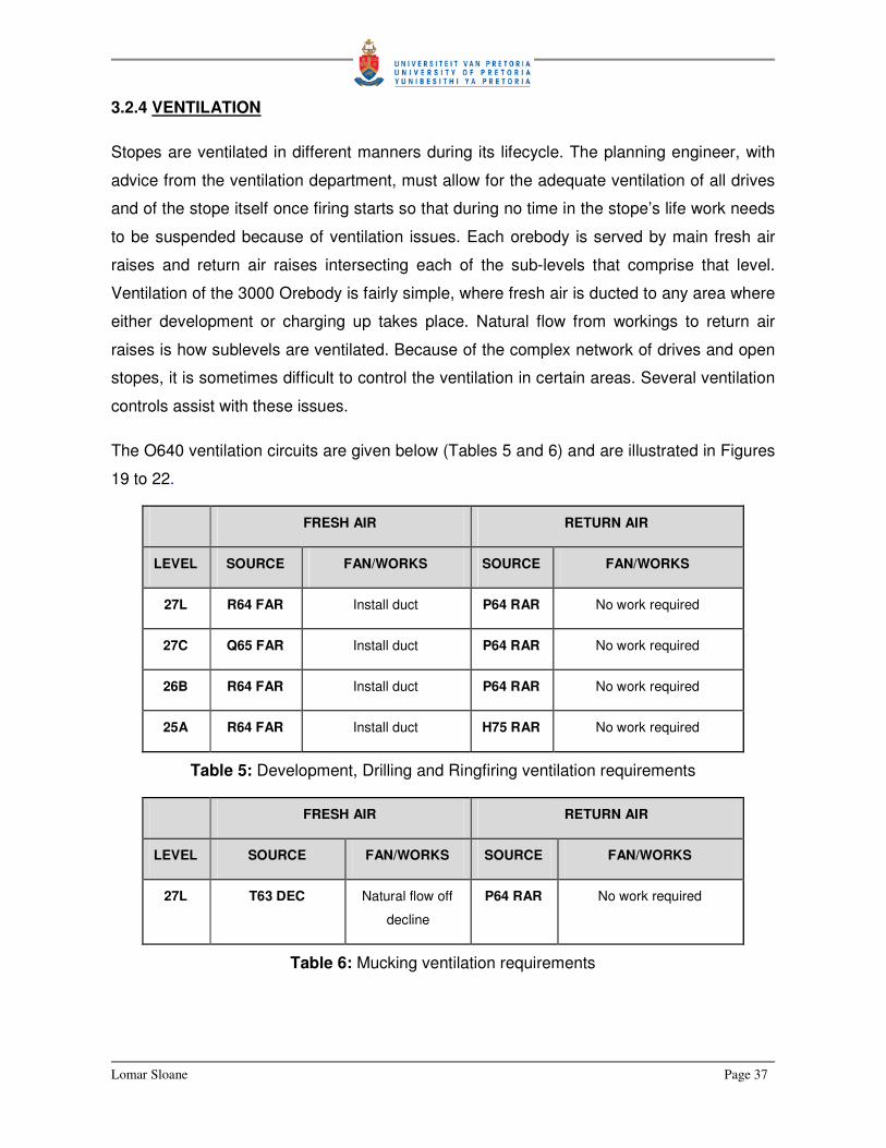
3.2.4 VENTILATION
Stopes are ventilated in different manners during its lifecycle. The planning engineer, with
advice from the ventilation department, must allow for the adequate ventilation of all drives
and of the stope itself once firing starts so that during no time in the stope’s life work needs
to be suspended because of ventilation issues. Each orebody is served by main fresh air
raises and return air raises intersecting each of the sub-levels that comprise that level.
Ventilation of the 3000 Orebody is fairly simple, where fresh air is ducted to any area where
either development or charging up takes place. Natural flow from workings to return air
raises is how sublevels are ventilated. Because of the complex network of drives and open
stopes, it is sometimes difficult to control the ventilation in certain areas. Several ventilation
controls assist with these issues.
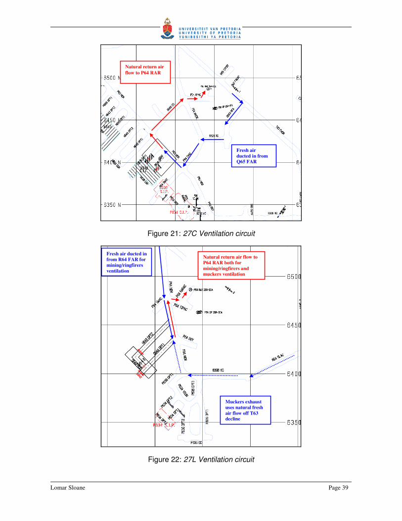
The O640 ventilation circuits are given below (Tables 5 and 6) and are illustrated in Figures
19 to 22.
FRESH AIR RETURN AIR
LEVEL SOURCE FAN/WORKS SOURCE FAN/WORKS
27L R64 FAR Install duct P64 RAR No work required
27C Q65 FAR Install duct P64 RAR No work required
26B R64 FAR Install duct P64 RAR No work required
25A R64 FAR Install duct H75 RAR No work required
Table 5: Development, Drilling and Ringfiring ventilation requirements
FRESH AIR RETURN AIR
LEVEL SOURCE FAN/WORKS SOURCE FAN/WORKS
27L T63 DEC Natural flow off
decline
P64 RAR No work required
Table 6: Mucking ventilation requirements

Lomar Sloane Page 38
Figure 19: 25A Ventilation circuit
Figure 20: 26B Ventilation circuit
Fresh air ducted in from V62 FAR
Natural return air flow to H75 RAR
Fresh air ducted in from R64 FAR
Natural return air flow to P64 RAR
Lomar Sloane Page 39
Figure 21: 27C Ventilation circuit
Figure 22: 27L Ventilation circuit
Fresh air ducted in from Q65 FAR
Natural return air flow to P64 RAR
Natural return air flow to P64 RAR both for mining/ringfirers and muckers ventilation
Fresh air ducted in from R64 FAR for mining/ringfirers ventilation
Muckers exhaust uses natural fresh air flow off T63 decline

Lomar Sloane Page 40
3.2.5 SERVICES
There is no service work required for this stope.
This is a section within the final design, which specifically deals with what services are
needed so that work on the designed stope can start. This is not so much a design
component, but it is the responsibility of the planning engineer to determine what is needed
and where it is needed as services that are installed will probably be used for future stopes
as well. In some cases cable holes and drain holes must service the stope/s and the
planning engineer is responsible that these holes are drilled from the appropriate place to
desired breakthrough point without passing through any other mine opening or planned
future opening if it is to serve future stopes.
3.2.6 FILLING
Stopes are filled after they have been mined. This is for the alleviation and redistribution of
stresses in and around stopes. Stopes cannot be left void as they will eventually start to
deteriorate and cave. Once caving started it will not easily stop and much of the mine
infrastructure and reserves can be lost in such failures. In the 3000 orebody, different types
of backfill have been used for stope filling. Most of these aren’t in use any more and backfill
for the 3000 orebody consists mainly of cemented hydraulic fill (CHF) and paste fill. The
preferred fill type is paste as it is a slurry type backfill with very little water drainage
compared to the large quantities of water associated with CHF filling. Continuous problems
are encountered with flooded workings due to the excessive water drainage out of stopes
that was CHF filled.
Once a stope is empty, it is bulk-headed (sealed) off. A bulkhead is a wall built to keep fill
inside the stope. It is equipped with drains that reach into the stope which assists with stope
drainage. With the quantities of fill that is placed in stopes in short periods of time, pressure
builds up behind these bulkheads, which can (and have in the past) failed causing mud
rushes and fatal injuries on mines. With paste these failures may still occur, but the mud
rush will choke itself off over a much smaller distance due to the lack of water, hence it
contains lower risk in usage. Mount Isa mines are trying to fill all stopes in the 3000 and
3500 orebodies with paste fill only. At this stage, the capacity to do so is not there and CHF
fill is used in conjunction with paste.

Lomar Sloane Page 41
The filling of a stope is the responsibility of the mine planning engineer. Even though the
subject of filling a stope is considered in the final design phase, a Fill Note is only drawn up
once the stope is empty and exact volumes have been determined.
“O640 is currently scheduled to be filled with CHF. This should pose no major problems
given the stope geometry and the fact that there are two DPT’s for stope drainage and
another two bulkheads that will assist in drainage once fill levels reach 27C, which is only
about 20m above 27L. CHF is currently piped to the 3000 orebody via the fill line in 360XC
on 24A and to 390XC on 25A and then along R63 NDR. O636 lines then divert into Q64
SWXC. Lines are currently set up for the filling of O636, but need only be swung around
into O640 FPAC to reach the COLHW, which will be used to fill the stope.
Should it be required that the stope be filled using paste at the time, then paste can be run
to O640 FPAC from lines that are currently being set up along R63 NDR 25A for the filling
of K672.” (Quoted from Sloane, 2006)
3.2.7 EXTRACTION OPTIONS
It must be noted that by this time the design is in fact more than half complete as overall
stope shape has been set and existing development will largely pre-determine where
access to the stope can be placed. This section, as described in the extraction below, looks
at the options that remains and key decisions made regarding the mining of this stope as
well as the reasons behind these decisions.
“Several aspects were considered in regard to extraction options for O640 stope. Key
aspects include existing development, grade contours and the interaction of O640 with
stopes already extracted and future stopes. Options were mainly restricted to stope
boundary position, placement of the CO slot and drawpoint design on 27L.
• The reserve shape for O640 remained largely unchanged with the exception of the
north-eastern boundary. The P63 NDR on 27C and M65 SEDR on 26B north-eastern
sidewalls run on the initial reserve shape floorplan for O640. This means that in order to
drill and shape the north-eastern wall of O640, that hole positions would have had to be
moved away from the boundary to fit the rig and then dumped to reach desired end
Lomar Sloane Page 42
positions. The result would have meant an uneven stope wall, which would influence
the design of P643 and could also lead to unwanted failures during the actual
production phase of O640. Because of this the boundary was moved 1m towards the
south-west and boundary holes can now be drilled vertically on all drilling sublevels.
• The placement of the CO slot was determined by development requirements on 25A
and existing development on 27C. O640 will be top exhausted via 25A-26B COLHW,
which also doubles as a fill pass once the stope finished production. The CO slot could
have been placed in either O638 DPT1 or O638 DPT2. Development design for 26B
would then only be required to align with whichever DPT was chosen. O638 DPT2 was
chosen because this would then yield the least development required on 25A for the
O640 FPAC. This also has the advantage that we now have a single COLHW straight
from 25A to 27L. (See figure 13)
• The O640 FPAC could have extended from either R63 NDR or Q64 SWXC in order the
reach the desired position of the fill pass. The decision was made to develop the FPAC
from Q64 SWXC so as to minimise the development for this stope. The downside was
that should we have used R63 NDR, the position could have been selected so that
some of the required development of P643 is then already completed. This was,
however, not done as it would ultimately fix the position of the future CO for P643 and
restricts design options for P643 considerably. In this way P643 is not at all influenced
(on 25A sublevel) by the design for O640. See Figure 7. Also, R63 NDR is the host
drive for all major services for the 3000 OB (CHF and Paste lines, etc.) and to develop
out of this drive would interrupt these services considerably, which would lead to delays
in several other areas.
• Two drawpoints are required for O640 when taking into account the location of the CO
slot and the stope dimensions require more than one drawpoint for the optimum
extraction of ore. This also favours the geometry of P643, which is similar to that of
O640 and will also be extracted from the same level as O640. The current DPT design
also serves as the future drawpoints for P643.”
(Quoted from Sloane, 2006)

Lomar Sloane Page 43
3.2.8 DESIGN FEATURES
The design features section of the final design is basically a summary of the stope to date.
Here special emphasis is placed on the smaller or more detailed design features and
include final stope dimensions, drilling layouts, stope extraction, etc. This is still a summary
and most of the aspects mentioned here is to give the reader an idea behind the stope
design and how things will be done.
“O640 lies centrally within the 3000 orebody and is designed to yield approximately 211,611
tons @ 4.77%. The stope will be drilled from two sublevels; 26B and 27C, but
development requirements for the production of the stope include levels 25A, 26B, 27C and
27L. O640 is approximately 92m in height, 35m wide and 28m in length. The CO is located
towards the south-east of the stope and aligns with O640 CO (to be developed) on 26B,
O638 DPT2 on 27C and O640 DPT1 (to be developed) on 27L.
O640 is to be drilled from 26B and 27C sublevels and includes a CO and MR’s. 27C will be
drilled using 102mm holes for the CO and all MR’s. The decision to do this is based on the
availability of the 102mm rig (2232) and by drilling from 27C down to 27L with 2232 it is
possible to effectively shape the stope floor without needing to drill and fire any TUC’s.
Obviously, the use of the 102mm rig is subject to availability at that time as 2232 is
scheduled to mainly serve X41. This means that the eventual design could actually be for
the use of 140mm down holes from 27C-27L. By drilling down holes from 27C-27L,
whether 140mm or 102mm, up holes will be restricted to 26B only. 140mm holes will be
used for drilling from 26B down to 27C. In using different sized down holes, the amount of
MR’s will differ from 26B-27C and 27C-27L. 26B - 27C will have 2x MR’s to the south-east
of the CO and 7x MR’s towards the north-west. 27C- 27L will have 3x MR’s to the south-
east of the CO and 9x MR’s towards the north-west. Should 140mm down holes be used
from 27C-27L, because 2232 is not available for use in O640, then the ring layout from
27C-27L will be the same as for 26B-27C. Boundary rings will be fired using Isanol 50 (low
density explosive).
Two drawpoints will be developed on 27L for the extraction of O640. These will also serve
as the drawpoints for P643. O640 DPT1 will be developed and will be stopped under
geology’s control, as the actual location of the Basement Contact (BC) may differ from that
in the DSS, as was the case with the development of N640 stope. DPT1 will be developed

Lomar Sloane Page 44
until it intersects the BC. Once the location of the BC is known, then DPT2 can be
completed and the DDR be developed. This may change the eventual stope shape, but
should only result in an altering of drill designs to cover any gain or loss in ore.
A COLHW will be drilled from 25A to 26B, from 26B-27C and from 27C-27L. This can be
seen in Figure 7. The COLHW will be fired through to 25A and will initially be used as a top
exhaust for O640, and after production, it will also be used as a pass for the filling of the
stope. The stope will be mucked from two drawpoints on 27L to P64 orepass which is a
tram of 95m one way (average between the two DPT’s) and then 270m one way on 30A
(ore is loaded again on this sub-level and tipped into the crusher).
(Quoted from Sloane, 2006)
3.2.9 SAFETY CONSIDERATIONS
Sub-level Open Stoping has three major safety issues, which must be addressed in the
stope final design. Should there be any other critical or stope specific issue then it will also
be addressed in the final design. Any other run of the mill safety issue will be identified,
assessed and addressed in the day to day working of the mine or as they arise. The
aspects that are mentioned here are a given no matter where, how, when or whatever the
stope design encompass. These include remote mucking, optechs (stope volume survey)
and bulkheads.
3.2.9.1 REMOTE MUCKING
Every stope is designed to be mucked remotely. This means that once the stope draws
close to empty (drawpoints clear of muck) then the operator of the mucker is not allowed to
drive into an open stope and muck. He is to remotely muck the stope from a safe distance.
It is for this reason that it is included in the stope final design. It does sometimes happen
that a stope is stopped before remote mucking for reasons of poor grade, but this seldom
happens.
“Remote mucking of the stope will be through the two drawpoints, O640 DPT 1 and O640
DPT2 on 27L once the brow of the stope is exposed by more than 1m. The operator should
then cease conventional mucking procedures and remote muck the stope as is required by
the remote mucking procedure PRO-34-05-03. Because of the Basement Contact Zone
Lomar Sloane Page 45
(BCZ) and the stope design, the footprint of the stope is small, which limits the required
amount of remote mucking to a minimum.” (Quoted from Sloane, 2006)
3.2.9.2 OPTECHS
An Optech is the firing of laser beams into a stope to eventually obtain a digital image of the
stope void in order to calculate stope void volumes. This gives a highly accurate and
detailed image of how the stope has performed. This unfortunately requires the surveyors
to hang their equipment out over the edge of a stope. In any event, this is extremely
dangerous no matter what safety precautions taken, but is necessary for stope analysis as
well as the calculation of fill required for the eventual filling of the stope. Optechs are also
known as CMS (Cavity Monitoring Systems) and this is a major tool for reconciling stope
design to actual performance. Villaescusa (2004) emphasises the importance of this phase
of the SLOS mining process, but as can be seen, this is also considered a hazardous task.
“Optechs for O640 should be conducted from 26B in M65 SEDR on the north-western side
of the stope and also from 27C in P63 NDR on the south-eastern side of the stope. The
sites for the optechs will be inspected by the Area Responsible Planning Engineer before
any optech commences and monitored through the duration of the optech. Lanyard anchor
points should be used as per the site procedure at both locations to facilitate the survey of
the stope.” (Quoted from Sloane, 2006)
3.2.9.3 BULKHEADS
Bulkheads are built once the stope ceases production and is ready to be filled. In general,
bulkhead building is not hazardous, unless it is being built in the stope drawpoints. People
working in or around stope drawpoints run the risk of being seriously injured or even killed
by rocks falling in the stope and then being ejected out of the stope drawpoints. For this
reason it is required as a safety concern in the final design note and is required for all
stopes.
“Filling bulkheads in the drawpoints must have mullock bundwalls pushed up into the
drawpoints, which will be at least 4m high and 2m back from the brow, prior to the
bulkheads being built. O640 stope will require 6 shotcrete arched wetfill bulkheads for the
filling of the stope. The location and final placement of bulkheads will be determined once

Lomar Sloane Page 46
an optech for the stope is done and the area inspected by the Area Responsible Planning
Engineer and Drilling and Wetfill Supervisor.” (Quoted from Sloane, 2006)
3.2.10 RESERVES AND SCHEDULING
3.2.10.1 RESERVES
The stope that is being designed is most likely intersected by diamond drill holes used in
the past to get an estimation of copper deposits and grade for the area and to form a 3D
image of the resource. This image, along with its grade distribution is known as the block
model. When a stope is designed, it is necessary to know; with as high a degree of
confidence as possible, what the tonnes and grade for that stope is going to be. This is so
that the run of mine ore can be scheduled to be produced at as constant a grade as
possible. The metallurgists will then know what to expect and compensate accordingly in
order to maximise copper recovery. Because stopes tend to be mined over a period of
months (given stope sizes) and blasted in segments, the final design also requires the
stope to be divided into ring tonnes and grade. A typical stope includes a cut-off (cut-off
consists of initial series of firings to create a void or free face) and then a series of rings.
These rings can be main rings (parallel to cut-off), diaphragm rings (perpendicular to cut-
off) or expansion rings (rings either parallel or perpendicular to cut-off, but drilled for
reaching specific areas). These are the main ring types although other specialized ring
types do exist. Once the tonnes and grades for the individual rings are known, the grade
during production of the stope can be predicted with a fairly high degree of certainty and run
of mine ore tonnes and grades can also be better controlled. The individual rings can now
be scheduled in terms of tonnes and grade over the life of the stope.
“The design tonnes and grade for O640 are shown in Table 7. There are no tonnes rated
as high risk for this stope. The extraction tonnes and grade for the stope, based on values
calculated in the reserve calculation spreadsheet, is given as 208,206t @ 4,61% Cu. It
should be noted that the extraction values are lower than the original design values. This is
attributed to the subtracted planned and existing development within the stope, which is
more than the added expected overbreak for the stope as well as ore losses attributed to
flat bottom stopes. Design tonnes, calculated in MineSight, do not include overbreak or
development within the stope.” (Quoted from Sloane, 2006)

Lomar Sloane Page 47
Also note that reference is made to high risk tonnes, design tonnes and extraction tonnes.
High risk tonnes refer to ore within the stope boundary that is economically viable to mine,
but that the normal mining or designed stope extraction may result in some of the stope
reserve being lost. These tonnes are not scheduled and are viewed as a bonus should they
be successfully extracted. Obviously it is desired that no stope be designed to include high
risk tonnes, but in some cases this is unavoidable. Design tonnes are the tonnes and
grades calculated using the design software and are based on the current block model and
reserve shapes. The design tonnes are never the same as the extraction tonnes for the
stope, although both tonnages are estimated before the stope starts production. Extraction
tonnes includes possible overbreak and excludes development inside the stope boundaries.
The idea is to design a stope in such a way as to get the design and extraction tonnes as
close to each other as possible and to eventually have these closely resemble the tonnes
extracted.
O640 RING TONNES GRADE 26B-27C Cut-off 14,384 4.84% MR01 20,108 4.75% MR02 18,253 4.74% MR03 18,381 4.86% MR04 17,075 4.83% MR05 17,064 4.83% MR06 16,916 4.74% MR07 16,846 4.54% MR08 16,839 4.29% MR09 10,944 4.18% 166,810 4.68% 27C-27L Cut-off 3,670 4.60% MR01 3,815 4.48% MR02 3,656 4.43% MR03 3,675 4.31% MR04 3,727 4.91% MR05 3,608 5.23% MR06 3,663 5.39% MR07 3,555 5.38% MR08 3,003 5.37% MR09 2,943 5.50% MR10 3,040 5.68% MR11 3,143 5.76% MR12 3,303 5.70% 44,801 5.10% TOTAL 211,611 4.77%
Table 7: O640 Stope Design Tonnes

Lomar Sloane Page 48
3.2.10.2 SCHEDULING
The scheduling of any stope basically entails the scheduling of all activities associated with
the stope to ensure no mining activity interacts or negatively impact another mining activity
which may influence overall mine production. Scheduling includes the “when” component
for all activities ranging from development of drives specific to the stope through drilling,
firing and eventually the filling of the stope.
“O640 is currently scheduled to produce between August 2006 and January 2007. There
are limited interactions between the production of O640 and any other stope in the area.
The first direct interaction with production of O640 is the timely filling and curing of N640,
which must be completed before O640 can be produced. N640 is behind schedule by
approximately 2 weeks at the time of writing this FD. The second interaction is with P635
production. O640 DPT development must be completed before P635 production can start
as P635 extraction takes place on 27L. There is no delay scheduled between end of
production of P635 and the start of production for O640, which would have offered a
window to complete O640 development. Should P635 start production before O640
development is complete, then O640 will be pushed back in the current schedule. At the
time of drafting of this FD, one 3000 and one 3500 OB stope is being drilled. After this
another eight stopes for enterprise is scheduled to be completely drilled by August 2006.
This leaves very little time for any deviation from schedule so cognisance of this must be
taken as the possibility exist that O640 may slip in position with reference to the current
schedule. Cognisance must also be taken in the fact that currently scheduled filling of P635
coincides with O640 production. Drainage water from P635 could interfere and delay
mucking operations in O640, but a more detailed investigation will be done closer to the
scheduled filling time of P635.”
(Quoted from Sloane, 2006)

Lomar Sloane Page 49
3.2.11 ECONOMIC ANALYSIS
“Economic analysis was carried out using Cash Margin Model CashCu37d, updated with
copper price, exchange rate (USD/AUD), copper treatment and refining cost assumptions
and to include budget and actual cost information to November 2004.
CashCu37d has not yet been updated with the 2006 budget assumptions. The 2006
budget assumptions are more closely reflected by the assumptions made for 2005 in
CashCu37d rather than those made for 2006. As such O640 has been analysed using the
2005 assumptions in the model rather than 2006.
The budget direct unit cost in Cash Margin Model CashCu37d is assumed to be the same
for both X41 and Enterprise. At present all copper production is being sold as cathode.
Results from the cash margin model analysis (2005 Assumptions) are shown in Table 8.”
(Quoted from Sloane, 2006)
The final design as it pertains to the planning engineer requires that the engineer perform
an economic evaluation of the stope designed to ensure that it is economically viable. The
analysis is based primarily on supplied model and spreadsheets, and more detailed
financial planning and budgeting is done by the senior planning engineers and the
scheduling engineers. For the scope of the final design, the planning engineer wants to see
if the stope is profitable or not. In the case of marginal stopes, the input of other engineers
will be required to re-design the stope to make it more profitable, or re-schedule the stope
to be mined in conjunction with higher grade stopes. In the case of the 3000 and the 3500
orebodies, the grade of these areas are such that the stopes will be profitable, the aim here
is more on optimising and getting most out of the stope. There are other areas at Mount Isa
mines where the grade is lower and financial analysis of stopes takes higher priority.
Concentrate Cathode
Stope Total Cashflow Cash Margin
($/ t)
Total Cashflow Cash Margin
($/ t)
O640 $9,808,682 $47.11 $17,341,790 $83.29
Table 8: Financial Results for O640 Stope

Lomar Sloane Page 50
3.2.12 STOPE PHYSICAL DATA SUMMARY
GENERAL STOPE DATA: O640
O640 1-SLOS
Top Sub-Level 25A Design Tonnes (t) 211,611
Sub-level 26B Design Grade (%) 4.77%
Sub-level 27C Scheduling Tonnes (t) 208,206
Mucking Level 27L Scheduling Grade (%) 4.61%
High Risk Tonnes (t) -
High Risk Grade (%) -
Note: Scheduling Tonnes and Grade includes expected overbreak tonnage as well as
development ore already removed at the time of production and factored for recovery.
DEVELOPMENT AND REHABILITATION DATA:
Sub-level Drive Name Type of Mining / Rehab Metres
Require
d
Comments
27L O640 DTP1 MINING 49
27L O640 DPT2 MINING 52
27L O640 DDR MINING 16
27C O638 DPT1 FILL MINING 12
REHAB 22
27C O638 DPT2 FILL MINING 10
REHAB 18
26B O640 CO MINING 25
25A O640 FPAC MINING 23

Lomar Sloane Page 51
PRODUCTION DRILLING DATA:
Sub-level Diameter Type Drill Metres Comments
25A 140 COLHW 681
26B 140 CO & MR’s 7025
89 CO & MR’s 1470
27C 102 CO & MR 4766
FILLING DATA:
Sub-level Bulkhead
Type
Number Required
27L FILL BH 2 Fill Type CHF
27C FILL BH 2 Fill Volume (m3) 73,732
26B FILL BH 2 Filling Horizon 25A
Fill Hole Collar Level -
Fill Hole No. Required -
Fill Hole Diameter (mm) -
Fill Hole Length (m) -
Fill Line Length to install
(m)
25
Fill Curing Time (days) 90
MP / Tip Level -
LHW or Raisebore COLHW
used for
top exhaust
and filling

Lomar Sloane Page 52
3.3 CONSIDERING OTHER DESIGN ISSUES
The O640 stope design considers most of the design parameters pertaining to a SLOS
design. There are, however, some instances where unique issues arise that are specific to
a given stope. In this section two such stopes, each with their own unique issues, will be
discussed. Note that only the issues will be discussed and not the whole design philosophy,
as this is the same as for O640. The complete Stope Final Designs for the L651 and the
N659 stopes are included in Annexure 2 and 3.
3.3.1 THE L651 STOPE
The L651 stope is a relatively small scavenger stope located within the central 3000
orebody. The PD for the stope was for a 58,480t @ 3.29% Cu stope lying between the 26B
and 27C sublevels. This is shown in Figure 23.
Figure 23: L651 Preliminary Design
26B
27C
Preliminary Stope Shape
Existing Drives
Planned Drives

Lomar Sloane Page 53
Initially the design was fairly straightforward with minimum development required to quickly
take the stope. Issues, however, arose with reviewing grade contours in determining a final
design stope shape. The PD was done some time ago and was based on the 2004
resource block model.
Figure 24: L651 Preliminary Design with 2005 Block Model
The block model is updated yearly and includes new diamond drill and mapping data. In
this way the block model is kept as up-to-date as possible. The final design of L651 was
done using the 2005 (latest) block model. The model showed a high grade pod of copper
ore just below the proposed preliminary design shape for the stope stretching across the
whole length of the stope. This is shown in Figure 24.
The pod of 5% Cu ore translates into approximately 18,500t of ore with a contained metal
value of in the region of A$ 6,607,000.00, which makes this worth while to reclaim. This pod
means a total re-design of the stope to include this ore, which is likely to include an
additional sublevel (27L) to act as the drawpoint level. It is important at this stage to realise
Area of high grade 5% Cu ore

Lomar Sloane Page 54
that no long term planning was done for the required amount of additional mining to include
another sublevel; hence no budget was set aside for this.
The problem was viewed from every possible angle, but it was found that the 5% pod could
only be taken by development on 27L to create access to the stope floor. Figure 25 shows
the development required on 27L to access L651.
Figure 25: L651 Final Design with Additional Required Development
As can be seen from Figure 25, significant additional development is required to mine the
additional copper ore. The decision was made to extract the stope from 27L, which
increased the stope size from 58,480t @ 3.29% Cu to 104,443t @ 3.55%. This is both an
increase in tonnes and grade. Unfortunately the decision to include another sublevel was
not the end of design issues. The following is a summary of the issues and the solutions
that arose as a result of the “discovery” of additional ore.
27L
27C
Additional Development required for the inclusion of the 5% Cu pod

Lomar Sloane Page 55
� Issue: Reaching the 5% Cu pod just below PD stope shape.
Solution: Include 27L into design to act s drawpoint level for L651 stope.
� Issue: The inclusion of 27L requires additional development possibly influencing future
stopes along this line.
Solution: Review and re-design 27L long term development requirements considering all
stopes surrounding L651 or any other stope possibly influenced.
� Issue: New sublevel development design optimum for all stopes in the area, but
drawpoints of 50m+ required, which means forced ventilation required.
Solution: Design a return air raise to the sublevel above to extract air from L651
drawpoints to the level above. This can be seen in Figure 25 as the vertical opening just
to the left of the stope.
These are the major issues that arose with the re-design of L651. One change in the design
causes a ripple effect, which forces changes throughout the design of the stope. In this
case, a design change in the beginning of the stope final design caused a ripple effect that
not only changed the whole stope, but also affected the mine production schedule as well
as surrounding future stope designs.
The complete Final Design for L651 can be viewed in Annexure 2.
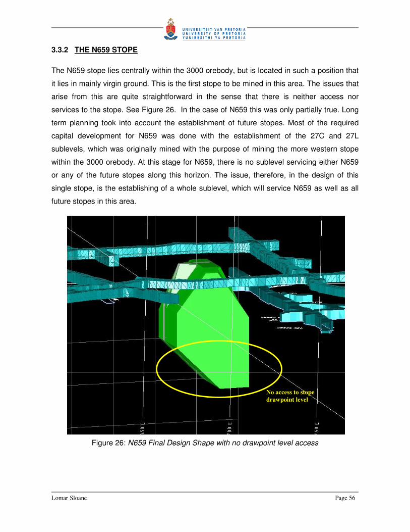
Lomar Sloane Page 56
3.3.2 THE N659 STOPE
The N659 stope lies centrally within the 3000 orebody, but is located in such a position that
it lies in mainly virgin ground. This is the first stope to be mined in this area. The issues that
arise from this are quite straightforward in the sense that there is neither access nor
services to the stope. See Figure 26. In the case of N659 this was only partially true. Long
term planning took into account the establishment of future stopes. Most of the required
capital development for N659 was done with the establishment of the 27C and 27L
sublevels, which was originally mined with the purpose of mining the more western stope
within the 3000 orebody. At this stage for N659, there is no sublevel servicing either N659
or any of the future stopes along this horizon. The issue, therefore, in the design of this
single stope, is the establishing of a whole sublevel, which will service N659 as well as all
future stopes in this area.
Figure 26: N659 Final Design Shape with no drawpoint level access
No access to stope drawpoint level

Lomar Sloane Page 57
The establishment of a new sublevel does not only pertain to the design of some
development ends to reach the stope. Several other aspects needs considering and must
be included in the overall sublevel design. The main aspects to consider are:
� Access from existing development to the proposed sublevel location.
� Service provision including:
o Electricity
o Compressed Air
o Water
o Drainage
� Establishing ore handling systems for this sublevel.
� Providing fresh air and return air points for this sublevel for adequate ventilation.
The mine as a whole includes various air raises for the provision of fresh and return air. In
the case of the establishment of the 28B sublevel, most of the mine fresh air, return air and
ore handling passes pass within close proximity to the proposed sublevel location. The
main design consideration is to tap into these raises and passes in such a way to effectively
service the new sublevel, but without influencing any other part of the mine.
The obvious starting point with the establishment of a new sublevel is at what depth and
how do we get to this area. Figure 27 shows N659 stope with infrastructure in the
immediate area. Development existing for the upper levels of this stope was discarded and
not shown in Figure 27, as these levels were never designed to accommodate mining lower
down. 28B sublevel needed to be completely new and feeds off main mine infrastructure
with as little influence from other sublevels as possible.
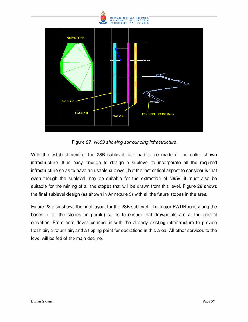
Lomar Sloane Page 58
Figure 27: N659 showing surrounding infrastructure
With the establishment of the 28B sublevel, use had to be made of the entire shown
infrastructure. It is easy enough to design a sublevel to incorporate all the required
infrastructure so as to have an usable sublevel, but the last critical aspect to consider is that
even though the sublevel may be suitable for the extraction of N659, it must also be
suitable for the mining of all the stopes that will be drawn from this level. Figure 28 shows
the final sublevel design (as shown in Annexure 3) with all the future stopes in the area.
Figure 28 also shows the final layout for the 28B sublevel. The major FWDR runs along the
bases of all the stopes (in purple) so as to ensure that drawpoints are at the correct
elevation. From here drives connect in with the already existing infrastructure to provide
fresh air, a return air, and a tipping point for operations in this area. All other services to the
level will be fed of the main decline.
N67 FAR
O66 RAR T63 DECL (EXISTING) O66 OP
N659 STOPE

Lomar Sloane Page 59
Figure 28: Final Design for 28B sublevel
When designing a new sublevel, a few questions need to be asked and answered. These
include:
� Where will the rest of the stopes be in this area – This will determine where the major
sublevel drive (FWDR) will run.
� How do we get to the stopes – Typically the closest major decline or other major
development end will be used to reach the desired FWDR location.
� How will we ventilate the area – The location of the closest FAR and RAR must be
known and it must be viable to tap into these for ventilation purposes.
� Where will we tip – No stope can be mined if the ore cannot be tipped somewhere. The
closest (the closer the better) OP will have to be accessed before any mining can
commence, otherwise difficult and expensive ore and waste removal from the sublevel
may ruin a profitable stope.
� What else – Other aspects to consider would include:
o Drainage of mine water
o Electricity feed

Lomar Sloane Page 60
o Compressed air and water
o Bomb bays
Numerous other aspects have to be considered, but seldom would stop the establishment
of a new sublevel. These issues are considered at this stage, but closer attention to the
finer details is usually given closer to the time of actual mining. The four questions asked
resemble some of the ideas and design methodologies as discussed in detail by Stacey
(2009). Stacey is not primarily concerned with practical application of design
methodologies, as his dissertation is mainly about comparing design philosophies. But here
we can see its practical import.
The complete Final Design for N659 can be viewed in Annexure 3.
Lomar Sloane Page 61
4. Conclusion
Although there are definite similarities between sub-level open stopes, each and every
stope also has a component to it that make it completely different from the next. This
dissertation was drafted with the intention to explain the role of the Mine Planning Engineer,
but more importantly the work performed by the engineer. It looks at the design
methodology that is needed to successfully design a sublevel open stope, but also, and
very important, it looks at applying theory into practise by means of example designs.
The design of sub-level open stopes is complicated process with numerous design
considerations, all of which must be accounted for during the design of the stope. For this
reason it is necessary to approach every design systematically. The O640, L651 and N659
stope final designs are examples and results of this systematic approach, but they also
clearly illustrate that even though there are similarities, there are also large differences
between designs.
The O640 stope was used as the design example in this dissertation as it will be the first
stope to be mined. The design was analysed and explained to give the reader an
understanding as to how and why certain decisions are made.
To some the role of the Mine Planning Engineer may seem straightforward and even not
that difficult. The three stopes used in this report have a combined design tonnage of
547,818t of Cu ore at an average grade of 3.91% Cu content. This equals a contained
metal content of 21,420t of copper. In monetary terms this is approximately
AU$152,997,741.00 worth of copper at the time the designs took place.
There is very little room for error in mining given the nature of the work underground, the
large quantities of rock moved and the large sums of money involved. The Mine Planning
Engineer must ensure that with good, well thought through designs, great results are
achieved.
Lomar Sloane Page 62
5. References
Bieniawski, Z.T., 1992, Invited Paper: Principles of engineering design for rock mechanics,
Rock Mechanics, Proc. 33rd U S Symp. on Rock Mech. Tillerson and Wawersik (eds.),
Balkema, 1992. pp. 1031–1040.
Cummins, A.B., Given, I.A., Hartman, H.L., 1992, Mining Engineering Handbook 2nd
Edition, Society for Mining, Metallurgy and Exploration, Inc., pp 1717-1731.
Esterhuizen, H., 2005, Rock Mechanics Stope Note – O640, Internal Mine Report, Mount
Isa Mines, Queensland, Australia
Esterhuizen, H., 2006, L651 Rock Mechanics Stope Note, Internal Mine Report, Mount
Isa Mines, Queensland, Australia
Esterhuizen, H., 2006, N659 Rock Mechanics Stope Note, Internal Mine Report, Mount
Isa Mines, Queensland, Australia
FRM 45-03-02, Copper Mines Final Design Note, Mine Standard Forms (Code of
Practice), Mount Isa Mines, Queensland, Australia
Gertch, R.E., Bullock, R.L., 1998, Techniques in Underground Mining: Selections from
Underground Mining Methods, Society for Mining, Metallurgy and Exploration, Inc., pp 45-
86, pp 223-247.
Harper, S., 2005, Geological Stope Note for: O640 PD, Internal Mine Report, Mount Isa
Mines, Queensland, Australia
Harper, S., 2006, L651 Geology Stope Note, Internal Mine Report, Mount Isa Mines,
Queensland, Australia
Harper, S., 2006, N659 Geology Stope Note, Internal Mine Report, Mount Isa Mines,
Queensland, Australia
Hustralid, W.A, Bullock, R.L., 2001, Underground Mining Methods: Engineering
Fundamentals and International Case Studies, Society for Mining, Metallurgy and
Exploration, Inc., pp 1-80, pp 205-286

Lomar Sloane Page 63
Hustralid, W.A., 1982, Underground Mining Methods Handbook, Society of Mining
Engineers of the American Institute of Mining, Metallurgical, and Petroleum Engineers, pp
364-374
Ilbury, C., and Sunter, C., 2005, The Games Foxes Play – Planning for Extraordinary
Times. Human & Rousseau / Tafelberg
OneMine: http://www.OneMine.org/
Pakalnis, R.T., 1986, Empirical Stope Design at the Ruttan Mine, Sherrit Gordon Mines
Ltd., University of Brittish Columbia.
Sandvik Tamrock, 1999, Rock Excavation Handbook for civil engineering, Publisher not
specified.
Sloane L., 2006, O640 Final Design, Internal Mine Report, Mount Isa Mines, Queensland,
Australia
Stacey, T.R., 2009, Design – A Strategic Issue, The Journal of the South African Institute of
Mining and Metallurgy Volume 109, pp 157-162.
STD 45-03-03, Copper Mines Final Design, Mine Standard Guidelines (Code of Practice),
Mount Isa Mines, Queensland, Australia
Steward, D.R., 1981, Design and Operation of Caving and Sublevel Stoping Mines, Society
of Mining Engineers of AIME, pp 627-633.
Uggalla. S., 2001, Sublevel open stoping: Design and planning at the Olympic Dam Mine.
In: HustralidW.A., and Bullock R.L., (2001): Underground Mining Methods, Society for
Mining Metallurgy and Exploration, Inc., pp 239-244
Villaescusa, E., 2004, Quantifying Open Stope Performance, MassMin2004.
Xstrata Reference, 2004, New Personnel – Copper Mines Reference File: Planning –
Surveying – Ring Design – Drafting, Mount Isa Mines, Queensland, Australia
Xtrata Mines DSS, Mine Database & Mine Records , Mount Isa Mines, Queensland,
Australia


![Aula 1.ppt [Modo de Compatibilidade] - ct.ufrgs.br Subterranea aula 1.pdf · dentro dos realces (shrinkage) ou por material externo ... Sub Level Stoping (Realce em sub níveis) •](https://static.fdocuments.net/doc/165x107/5bb26eb109d3f2272e8cda96/aula-1ppt-modo-de-compatibilidade-ctufrgsbr-subterranea-aula-1pdf-dentro.jpg)