Sub-1V CMOS Bandgap Reference for Ultra-Low Power Applications

Sub 1 V CMOS bandgap reference design techniques: a survey
Christian Jesus B. Fayomi Æ Gilson I. Wirth ÆHerve Facpong Achigui Æ Akira Matsuzawa
Received: 5 April 2007 / Revised: 8 July 2009 / Accepted: 23 July 2009 / Published online: 18 August 2009
� Springer Science+Business Media, LLC 2009
Abstract This paper presents a review of constraints,
limitation factors and challenges to implement sub 1 V
CMOS bandgap voltage reference (BVR) circuits in today’s
and future submicron technology. Moreover, we provide
insight analysis of BVR circuit architectures a designer can
relay upon when building CMOS voltage reference.
Keywords Low-voltage CMOS bandgap voltage
reference � Deep submicron � Operational amplifier �Dynamic threshold MOSFET
1 Introduction
Bandgap voltage references (BVR) are circuits that provide
a temperature and supply insensitive output voltage.
Voltage references are among the most important building
blocks in analog circuits and are used in dynamic random
access memory (DRAM), flash memories, power supply
generation, DC bias voltage, current sources, analog-to-
digital converters (ADCs), and digital-to-analog converters
(DACs). In addition, the performances and precision of
coders and/or decoders, as well as the conversion accuracy
of signal processing blocks in data converters systems are
strongly dependent on the accuracy of the reference volt-
age. Traditionally, the output reference voltage has always
been approximately equal to the intrinsic bandgap voltage
of the semiconductor material used, the silicon for instance.
In bandgap reference, an output voltage with low sensi-
tivity is obtained as the sum of a voltage that is propor-
tional to absolute temperature (PTAT) and a voltage with
negative temperature coefficient, which is complementary
to absolute temperature (CTAT). The PTAT voltage is
generated by taking the difference in the base-emitter
voltages of two bipolar transistors. The CTAT voltage is
usually obtained from the voltage across a forward biased
p–n junction or the base-emitter voltage (VBE) of a diode
connected bipolar junction transistor (BJT) as illustrated in
Fig. 1. The term VT indicated in this figure is the thermal
voltage described by Eq. 1, where k is the Boltzmann
constant, q is the electron charge and T is the temperature.
VT ¼kT
qð1Þ
In CMOS technology, parasitic vertical BJT transistors
formed in p- or n-well are used to implement BVR circuits.
The key parameters that specify the performance of BVR
circuits are expressed in terms of initial accuracy, tem-
perature insensitivity, supply current or power consump-
tion. Furthermore, immunity to power supply noise,
robustness to process variation, reliability, long term drift
and temperature hysteresis are among additional key
C. J. B. Fayomi (&) � H. F. Achigui
Wireless Smart Devices Labs, Computer Science Department,
Universite du Quebec A Montreal, President Kennedy Hall,
201 President Kennedy Avenue, PK-4630, Montreal,
QC H2X 3Y7, Canada
e-mail: [email protected]
H. F. Achigui
e-mail: [email protected]
G. I. Wirth
Departamento de Engenharia Eletrica, Federal University
of Rio Grande do Sul (UFRGS), Porto Alegre, RS, Brazil
e-mail: [email protected]
A. Matsuzawa
Department of Physical Electronics, Tokyo Institute
of Technology, Ookayama Campus, Tokyo, Japan
e-mail: [email protected]
123
Analog Integr Circ Sig Process (2010) 62:141–157
DOI 10.1007/s10470-009-9352-4

performances parameters. The initial accuracy of voltage
reference is referred as the output voltage at room tem-
perature and provides the starting point for most of the
other specifications. The temperature coefficient represents
the deviation of the output voltage because of changes in
the ambient or package temperature. The temperature
hysteresis outlines the amount of variation of the output
voltage after a cycle of temperature change. When the
references experience a temperature change and return to
the initial temperature, they frequently do not have the
same initial output voltage. This variation is caused by the
mechanical stress applied to the chip. The mechanical
stress is due to the difference in thermal coefficient of
expansion between the silicon chip, package and PC board.
As this type of error depends on temperature excursion,
reference design and type of package, it is difficult to
correct and it can considerably damages the reference
accuracy. The stability is a measure of the variation in the
output voltage after a long period of operation. The desired
performances of BVR circuits and systems are precise
initial accuracy, strong temperature insensitivity, low cur-
rent or power consumption, and low noise.
This tutorial presents a review of state-of-the-art design
techniques to implement sub 1 V BVR circuits that gen-
erate stable reference regardless of both temperature and
supply voltage variation. Reduced power supply voltage is
normally not an advantage for voltage reference design and
a low supply voltage may require some special circuit
techniques. Technology scaling and demand for low power
applications lead to lower supply voltages, below the
intrinsic bandgap voltage. An overview of the limitation
factors affecting the performance of BVR circuits is pre-
sented in Sect. 2. Section 3 is a review of the state-of-the-
art design techniques that have been recently proposed to
implement sub 1 V voltage reference. The summary is
presented in Sect. 4.
2 Design challenges of sub 1 V CMOS bandgap
references
Reference voltage generators are required to be stabilized
over process, voltage and temperature variations, and also
to be implemented without modification of fabrication
process. The conventional output voltage of BVR circuit is
1.25 V, which is nearly the same voltage as the bandgap of
silicon. This fixed output voltage of 1.25 V limits the
minimum supply voltage (VDD) operation. In addition, since
the main popular trends in the design of BVR circuits rely
on the usage of an operational amplifier (opamp) in the
PTAT current generation loop, the offset of the opamp
greatly affects the accuracy of the BVR circuit. Moreover,
the currents mirrors mismatch, the resistors mismatch, the
transistors mismatch, the emitter-base voltage (VEB) spread,
and the package shift are among the main dominant sources
of errors affecting the performance of BVR [1–6]. How-
ever, BVR circuit performance is limited by its absolute
accuracy (how close the output can be set to a desired value
at nominal operating condition) and its relative error (how
much the voltage varies from the nominal value over the
full range of operating condition). Moreover, for precision
applications such as in data converter systems, the relative
error of a voltage reference ultimately determines how
useful the circuit will be. The relative stability of a BVR
circuit is determined by the temperature coefficient of the
reference over the operating temperature range, the power
supply noise rejection (PSR) over the operating voltage
range, the load regulation over the range of output load
impedances, and the peak-to-peak output noise generated
by the intrinsic noise sources of the circuit [1].
2.1 Operational amplifier offset
The inherent random offset in MOSFETs transistors gate
source voltages which arises from the mismatches in
threshold voltages, W/L ratios, electron and hole mobilities,
results into opamp offset. The latter is directly superim-
posed onto the resistor RPTAT, in addition to the desired
difference of the emitter-base voltage (DVEB), and is
amplified by the same factor. Therefore, the opamp offset
voltage is the prevailing source of process induced error in
CMOS BVR architecture similar to Fig. 2.
2.2 Current mirror mismatch
When referring to Fig. 2, any mismatch in the required
current ratio of the current mirror formed by PMOS tran-
sistors M1–M2, would result in a difference in the current
flowing through the BJT transistors Q1–Q2. Deviation in
the current mirror are due to isolated and/or combined
effects of mismatch in the W/L ratio, threshold voltage
T
kTV
q= TV
∑BEV
ref BE TV V KV= +
DDV
TKV
Fig. 1 Block diagram of a bandgap voltage reference
142 Analog Integr Circ Sig Process (2010) 62:141–157
123

mismatch, channel length modulation effects of MOS
transistors, resistors mismatch. Moreover, for submicron
technologies, the short channel effects (SCE), the drain
induced barrier lowering effects (DIBL), and some addi-
tional stress such as the length of oxide definition (LOD)
effect on matched devices would contribute to additional
mismatch. These errors can be mitigate through layout
techniques such as the common centroid and compact
layout, dummy devices at no additional cost or by laser
trimming, which is a more expensive offset correction
technique. Another example of practice to improve the
current source matching is the addition of resistor R3,
otherwise devices M1 and M2 would have different drain-
source voltages.
2.3 Resistor mismatch and resistor tolerance
Random process induced variation of the resistor value
directly affect the VEB and consequently the PTAT voltage.
The induced error in the output voltage (VREF) of BVR
circuit is given by Eq. 2
DVREF ¼ �VTdRA ð2Þ
where dRA is the fractional deviation of the resistors from
their nominal values [2]. Resistors mismatch affect the
PTAT voltage as given by Eq. 3
DVREF ¼ VPTATdRR ð3Þ
where dRR is the mismatch in the resistors. For example,
considering the topology shown in Fig. 2, the PTAT
current and the output voltage are given by (4) and (5). If
the resistor R1 has a variation of ± DR1, the PTAT current
will suffer a variation of DI described by Eq. 6—where a is
the term that multiplies VT. This error will be amplified by
RPTAT at the output voltage, then generating an error
(DVREF) equal to -VT 9 dRA, where dRA is given by
–a 9 RPTAT.
IPTAT ¼DVBE
R1
¼ VT � lnðNÞR1
ð4Þ
VREF ¼ VBE2þ IPTAT � RPTAT ð5Þ
DIPTAT ¼DR1 � lnðNÞ
R1 � ðR1 � DR1Þ� VT ¼ a� VT ð6Þ
Layout techniques are the most efficient and non-costly
means to reduce the effect the resistors mismatch induced
errors. Especially, layout of resistors should be laid in a
square like structure and in a common centroid fashion.
Resistors material are preferably in polysilicon since its
offer the minimum separation of resistor fingers. Thus
providing a compact layout and better matching. In addi-
tion, a polysilicon resistor has a smaller resistance spread
over temperature than diffusion resistor. Also, when
available, lightly doped polysilicon is a better choice since
it has a negative temperature coefficient.
2.4 Transistor mismatch
The output voltage of traditional BVR circuit is basically
the sum of an emitter-base voltage and a scale value of the
thermal voltage. Any spread in VEB would have a large
effect in the relative error of the BVR. In addition, any
deviation in the area of transistors Q1–Q2 in Fig. 2, would
result in an error (DVREF), and is given by
DVREF ¼1
lnðNÞðVT þ VPTATÞdPNP ð7Þ
where dPNP is the fractional error in the transistors area
ratio [2–4].
2.5 Package induced offset
Package induced voltage shift is the difference between the
voltage reference caused by the local and die-wide
mechanical stress of a package in its encapsulated inte-
grated circuit (IC). This shift is caused by the stress
imposed by the package on the die surface. The dominant
factor is due to the difference in the thermal coefficient of
expansion of the silicon die and the plastic mold. The
plastic package transfers an increasing stress to the chip as
the package cools from molding to ambient temperature. A
common technique to reduce the effect of this error is to
use silica fillers that reduce the thermal expansion and
prevent destructive effects like corner and passivation layer
cracking as well as metal line shifts. Also, thick elastic film
layer between the plastic mold and the die surface can
absorb some of the stress from the plastic mold [6].
Fig. 2 Typical CMOS bandgap voltage reference
Analog Integr Circ Sig Process (2010) 62:141–157 143
123
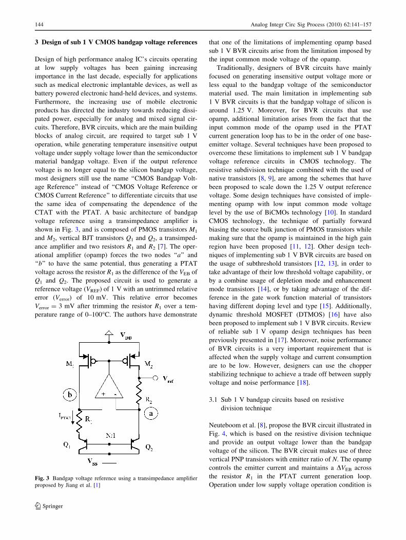
3 Design of sub 1 V CMOS bandgap voltage references
Design of high performance analog IC’s circuits operating
at low supply voltages has been gaining increasing
importance in the last decade, especially for applications
such as medical electronic implantable devices, as well as
battery powered electronic hand-held devices, and systems.
Furthermore, the increasing use of mobile electronic
products has directed the industry towards reducing dissi-
pated power, especially for analog and mixed signal cir-
cuits. Therefore, BVR circuits, which are the main building
blocks of analog circuit, are required to target sub 1 V
operation, while generating temperature insensitive output
voltage under supply voltage lower than the semiconductor
material bandgap voltage. Even if the output reference
voltage is no longer equal to the silicon bandgap voltage,
most designers still use the name ‘‘CMOS Bandgap Volt-
age Reference’’ instead of ‘‘CMOS Voltage Reference or
CMOS Current Reference’’ to differentiate circuits that use
the same idea of compensating the dependence of the
CTAT with the PTAT. A basic architecture of bandgap
voltage reference using a transimpedance amplifier is
shown in Fig. 3, and is composed of PMOS transistors M1
and M2, vertical BJT transistors Q1 and Q2, a transimped-
ance amplifier and two resistors R1 and R2 [7]. The oper-
ational amplifier (opamp) forces the two nodes ‘‘a’’ and
‘‘b’’ to have the same potential, thus generating a PTAT
voltage across the resistor R1 as the difference of the VEB of
Q1 and Q2. The proposed circuit is used to generate a
reference voltage (VREF) of 1 V with an untrimmed relative
error (Verror) of 10 mV. This relative error becomes
Verror = 3 mV after trimming the resistor R1 over a tem-
perature range of 0–100�C. The authors have demonstrate
that one of the limitations of implementing opamp based
sub 1 V BVR circuits arise from the limitation imposed by
the input common mode voltage of the opamp.
Traditionally, designers of BVR circuits have mainly
focused on generating insensitive output voltage more or
less equal to the bandgap voltage of the semiconductor
material used. The main limitation in implementing sub
1 V BVR circuits is that the bandgap voltage of silicon is
around 1.25 V. Moreover, for BVR circuits that use
opamp, additional limitation arises from the fact that the
input common mode of the opamp used in the PTAT
current generation loop has to be in the order of one base-
emitter voltage. Several techniques have been proposed to
overcome these limitations to implement sub 1 V bandgap
voltage reference circuits in CMOS technology. The
resistive subdivision technique combined with the used of
native transistors [8, 9], are among the schemes that have
been proposed to scale down the 1.25 V output reference
voltage. Some design techniques have consisted of imple-
menting opamp with low input common mode voltage
level by the use of BiCMOs technology [10]. In standard
CMOS technology, the technique of partially forward
biasing the source bulk junction of PMOS transistors while
making sure that the opamp is maintained in the high gain
region have been proposed [11, 12]. Other design tech-
niques of implementing sub 1 V BVR circuits are based on
the usage of subthreshold transistors [12, 13], in order to
take advantage of their low threshold voltage capability, or
by a combine usage of depletion mode and enhancement
mode transistors [14], or by taking advantage of the dif-
ference in the gate work function material of transistors
having different doping level and type [15]. Additionally,
dynamic threshold MOSFET (DTMOS) [16] have also
been proposed to implement sub 1 V BVR circuits. Review
of reliable sub 1 V opamp design techniques has been
previously presented in [17]. Moreover, noise performance
of BVR circuits is a very important requirement that is
affected when the supply voltage and current consumption
are to be low. However, designers can use the chopper
stabilizing technique to achieve a trade off between supply
voltage and noise performance [18].
3.1 Sub 1 V bandgap circuits based on resistive
division technique
Neuteboom et al. [8], propose the BVR circuit illustrated in
Fig. 4, which is based on the resistive division technique
and provide an output voltage lower than the bandgap
voltage of the silicon. The BVR circuit makes use of three
vertical PNP transistors with emitter ratio of N. The opamp
controls the emitter current and maintains a DVEB across
the resistor R1 in the PTAT current generation loop.
Operation under low supply voltage operation condition isFig. 3 Bandgap voltage reference using a transimpedance amplifier
proposed by Jiang et al. [1]
144 Analog Integr Circ Sig Process (2010) 62:141–157
123

achieved by connecting the resistor R3 across the bandgap
reference, and the resulting output voltage becomes a
fraction of the bandgap voltage which is given by
VREF ¼R3
R2 þ R3
ðVEB þ IPTATR2Þ ð8Þ
which can be scaled to any value. A fraction of the bandgap
voltage is obtained by proper choice of resistors R2 and R3.
The proposed circuit achieves an output voltage of 0.67 V,
under a minimum supply voltage of 0.9 V. Similar
technique to generate output voltage lower than the
material bandgap have been used by Banba et al. [9], and
Malcovati et al. [10]. Banba et al. proposed the CMOS
BVR circuit illustrated on Fig. 5. In this BVR circuit, two
currents that are proportional to voltages at nodes a and b
are generated. The opamp is used to force the two voltages
Va and Vb to be equal thus producing a current in the
nominally equal resistors R2A and R2B proportional to VEB.
As a result the current in the PMOS transistors M1, M2 and
M3 (I1 = I2 = I3) is given by
I1 ¼VT lnðNÞ
R1
þ VEB
R2A
ð9Þ
and the output voltage is then given by Eq. 10, where N is
the emitter area ratio of the two diode connected bipolar
transistors Q1 and Q2.
VREF ¼R3
R2A
VTR2A
R1
lnðNÞ þ VEB2
� �ð10Þ
The theoretical minimum supply voltage for this circuit
architecture is VDDðminÞ ¼ VEB þ Vthp. The compensation of
the temperature coefficients of the thermal voltage VT and
VEB is achieved by choosing the values of N and of the
R2A/R1 ratio which satisfy
R2A lnðNÞR1
¼ 22 ð11Þ
For proper sub 1 V operation, the authors proposed an
opamp circuit based on native MOS transistors which are
not always available in standard digital CMOS technology
process. Moreover, these BVR circuits require the usage of
parasitic vertical PNP transistors included in CMOS pro-
cess, but which are not very well characterized. The ver-
tical PNP transistors are process dependent and offer
limited robustness to process variation as the doping gra-
dient, process parameters vary a lot within transistors of the
same die. Some design advantages, such as enhanced
insensitivity to ripple in the power supply and/or better
power supply rejection ratio (PSRR) performance could be
obtained using cascode devices in the current mirror but at
the expense of an increased of the minimum power supply.
The opamp used in BVR circuits are required to be fully
operational under sub 1 V condition. Since the output node
drives p-channel current sources, and considering that
|Vth,p| = 0.7, the output quiescent voltage should be
maintained to be around 0.15–0.2 V in order to maintain
the PMOS transistors current mirror in strong inversion.
Moreover, their input common mode voltage should be
maintained at value at least equal to one emitter-base
voltage of 0.65 V, even though the emitter-based voltage
of BJT decreases to value around 0.45 V when the tem-
perature is increased up to 100�C. Similar BVR core circuit
has been proposed by Malcovati et al. [10], and is depicted
in Fig. 6. The later enables designers to overcome the
limitation of the low input common mode voltage
requirement for the opamp and enhance the implementa-
tion of a sub 1 V BVR circuit by using the BiCMOS
process technology. The proposed BVR circuit has two
stable operating points and requires a start-up circuit to
prevent operation in the undesired operation point. In
addition, the circuit compensates for first order temperature
M2M1
+ -
R1
Q1 Q2
Vref
N:1
VSS
VDD
b
a
M3
R3IPTAT
Q3
R2
1:N
Fig. 4 Bandgap voltage reference circuit proposed by Neuteboom
et al. [8]
Fig. 5 Bandgap voltage reference architecture proposed by Banba
et al. [9]
Analog Integr Circ Sig Process (2010) 62:141–157 145
123

dependence only as outlined in Eq. 12. The VBE of a BJT
does not change linearly with temperature but according to
the relationship given by
VBEðTÞ ¼ VBG � ðVBG � VBE0ÞTT0
� ðg� aÞVT lnT
T0
ð12Þ
where g depends on the bipolar structure and is around 4,
while a equals 1 if the current in the BJT is PTAT and goes
to 0 when the current is temperature independent. The
current in the PMOS transistors of the bandgap circuit is
copied by using transistor M12 and injected into a diode
connected BJT transistor Q3. A VBE with a = 0 is produced
across Q3. The difference between VBE;Q3ðTÞ and
VBE;Q1;2ðTÞ leads to a voltage proportional to the
nonlinear term of Eq. 12
VNL ffi VBE;Q3ðTÞ � VBE;Q1;2
ðTÞ ¼ VT lnT
T0
ð13Þ
The opamp input stage is based on two grounded PNP
transistors as shown in Fig. 7. The bias current in the dif-
ferential pair of the opamp is a replica of the current in the
diode connected BJT of the bandgap structure, since tran-
sistor Q1 of the bandgap and Q3 of the input stage of the
opamp form a current mirror. This enables the designer to
overcome the need of having current source in the input
stage of the differential amplifier that required at least one
saturation voltage to operate properly. The current signal
generated by the input differential pair Q3–Q4 is folded and
collected by diodes connected MOS transistors (M6 and
M7). The resulting differential gain becomes
Ad ¼gm;BJT
gm;MOS
¼ IBJT=VT
2IMOS
�ðVGS � Vth;nÞ
ð14Þ
where the suffix BJT refers to the input BJT and the suffix
MOS refers to the diode loads M6 and M7. Using IBJT = 4
IMOS the gain obtained is 8 while having a fully
symmetrical input and a practically zero systematic
offset. The second stage is only a push-pull circuit.
Curvature compensation is achieved by subtracting, from
both I1 and I2, a current proportional to VNL. This is
obtained by adding nominally equal resistors R4 and R5,
which drain from M1 and M2 the required current (INL) as
shown in Fig. 6, and leading to output voltage of
VREF ¼R3
R2A
R2A lnðNÞR1
VT þ VBE þR2A
R4;5VNL
� �ð15Þ
The proposed BVR architecture achieves an output
voltage of 0.536 V with a temperature coefficient of
7.5 ppm/K when the temperature changes from 0�C to
80�C, and a voltage supply coefficient of 212 ppm/V.
Ker et al. [11], proposed a BVR circuit that provide a
fraction of the bandgap voltage by mean of resistive divi-
sion to reduce the input common mode voltage requirement
of the opamp, without using low threshold devices as
illustrated on Fig. 8. The proposed BVR circuit also
exploits the alternate connection technique of the opamp
input stage by connecting it to nodes V1 and V2 instead of
nodes a and b as was done in previous works. We should
recall that the main idea presented by Leung et al. and Ker
et al., being to provide alternate connection points of the
Fig. 6 Low voltage BiCMOS bandgap with curvature compensation
proposed by Malcovati et al. [10]
Fig. 7 Schematic of the two-stage opamp used in the voltage
reference proposed by Malcovati et al. [10]
Fig. 8 Bandgap voltage reference without using low threshold
devices proposed by Ker et al. [11]
146 Analog Integr Circ Sig Process (2010) 62:141–157
123

opamp input stage. The proposed BVR circuit generates an
output voltage of 0.238 V with a temperature coefficient of
58.1 ppm/�C, and the minimum supply voltage is 0.85 V.
3.2 BVR circuits that uses threshold voltage reduction
by forward biasing the substrate of the MOSFETs
Another limitation in implementing low voltage CMOS
BVR circuits is the threshold voltage that does not scale
down as the supply voltage. Leung et al. [19], proposed a
CMOS BVR circuit that achieves sub 1 V operation by
means of partially forward bias of the PMOS transistors to
reduce their threshold voltage. For the BVR circuit shown in
Fig. 9(a), the minimum input common mode voltage of an
opamp having NMOS input stage is required to be less that
one VEB(on) (i.e., Vth,n ? 2VDS (sat) \ VEB(on)), which implies
that transistors with Vth,n \ 0.6 V should be used assuming
VEB(on) = 0.7 V and VDS (sat) = 0.05 V. Even though
NMOS transistors with Vth,n \ 0.6 V can easily be found in
many submicron CMOS technologies, however, the tem-
perature effect on the base-emitter voltage and threshold
voltage should be considered. Given that the temperature
coefficient of the base-emitter voltage is approximately
-2 mV/K while that of threshold voltage of the NMOS
transistor may be greater than -2 mV/K, therefore at high
temperature VEB(on) may be less than Vth,n ? 2VDS (sat) and
the BVR circuit will not function properly. Thus either native
transistors or NMOS transistor with Vth,n \ 0.5 V are
required to allow the reference circuit to operate down to a
single 1-V supply. When the BVR circuit uses opamp having
PMOS input stage, as shown in Fig. 9(b), the minimum
supply voltage is VEB(on) ? |Vth,p| ? 2VDS (sat), and so
|Vth,p| \ 0.2 V is required to implement a 1-V reference,
which represents a major limitation. To address this limita-
tion, the reference core as proposed by Banba et al. [9], is
modified and the input of the opamp is connected to nodes a1
and b1 instead of nodes a and b as illustrated in Fig. 10. The
opamp enforces voltage at nodes a1 and b1 to be equal. As a
result voltages at nodes a and b are also equals when R2A1¼
R2B1and R2A2
¼ R2B2: The loop formed by Q1, Q2, R1, R2A1;
R2B1; R2A2
; and R2B2generates a current I given by
I ¼ VBE
R2
þ VT lnðNÞR1
ð16Þ
where N is the emitter area ratio, VT is the thermal voltage,
and R2 ¼ R2A1þ R2A2
¼ R2B1þ R2B2
: The current I is
injected to R3 by the current mirror formed by M1, M2
and M3 and gives the reference voltage as follows including
the effect of the offset voltage (Vos) of the opamp:
VREF ¼R3
R2
VEB2þ R2
R1
lnðNÞVT þR2
R2A2
VOS
� �� �ð17Þ
A fraction of the material bandgap voltage can be
obtained by an appropriate choice of resistor ratio of R3 to
R2. Moreover, trimming of the resistor ratio of R1, R2 to
achieve a good TC can be done on R2A1and R2B1
simul-
taneously. In addition, in order to minimize the error
introduced by the opamp offset voltage, the authors used a
larger emitter area ratio (N = 64), thus reducing the
required resistor ratio of R1, R2. The minimum supply
voltage is given by
M2
M1
+ -
R1
Q1
Q2
Vref
VSS
VDD
R2ba
IPTAT
N:1
M3
Q3
(a)
(b)
Fig. 9 Bandgap voltage reference in CMOS technology using an
amplifier with: a NMOS input stage, b PMOS input stage, proposed
by Leung et al. [11]
Analog Integr Circ Sig Process (2010) 62:141–157 147
123

min VDDf g ¼ R2B2
R2B1 þ R2B2
VEB2þ Vth;p
�� ��þ 2 VDS;ðsatÞ�� ��
ð18Þ
The proposed BVR circuit architecture achieves an
output voltage of 0.630 V with a temperature coefficient of
15 ppm/�C, and the minimum supply voltage is 0.98 V.
Traditionally, CMOS BVR circuits have been based on
the use of either vertical PNP or NPN BJT transistors.
Given that vertical NPN BJT transistors can be fabricated
within standard CMOS process by using a deep N-well
structure, Ker et al. [20] proposed a curvature compensa-
tion technique for CMOS BVR circuit that combine two
BVR circuits which are built by means of the NPN and
PNP as illustrated in Fig. 11. Two reference currents IREF1
and IREF2are generated from the BVR which use PNP and
NPN transistors, respectively and are given by:
IREF1¼
VBE;PNP
�� ��R1;PNP
þ 1
R3;PNP
kT
qlnðNPNPÞ ð19Þ
where R1,PNP = R1a,PNP ? R1b,PNP (or R2a,PNP ? R2b,PNP),
R1a,PNP = R2a,PNP, and R1b,PNP = R2b,PNP.
IREF2¼
VBE;NPN
�� ��R1;NPN
þ 1
R3;NPN
kT
qlnðNNPNÞ ð20Þ
where R1,NPN = R1a,NPN ? R1b,NPN (or R2a,NPN ? R2b,NPN),
R1a,NPN = R2a,NPN, and R1b,NPN = R2b,NPN. A temperature
independent current IREF is generated by taking the
difference between current mirrors formed by M4,PNP–
M5,PNP, and M4,PN–M5,NPN and feed into resistor RREF to
generate the output voltage VREF given by:
VREF ¼ RREF
"k2VBE;NPN
R1;NPN
�k1 VBE;PNP
�� ��R1;PNP
� �
þ kT
q
lnðNNPNÞR3;NPN
� lnðNPNPÞR3;PNP
� �# ð21Þ
Opamp offset voltage effects would contribute to
additional error voltage given by
DVREF;error ¼ RREF
k2R1;NPN
R1B;NPN
VOS;N �k1R1;PNP
R1B;PNP
VOS;P
� �ð22Þ
where VOS,N, and VOS,P, are the offset voltage of the opamp
used in the BVR circuit using NPN and PNP BJT,
respectively.The effect of VOS,N, VOS,P, can be reduced by
increasing the emitter area ratio of the BJTs (NPN and
PNP) and consequently, the required resistance ratio of
k2R1;NPN
�R1b;NPN and k1R1;PNP
�R1b;PNP would be reduced
Fig. 10 Sub 1-V bandgap voltage reference in CMOS technology
using an amplifier with: PMOS input stage proposed by Leung et al.
[11]
Fig. 11 Curvature compensated a bandgap voltage reference proposed by Ker et al. [20]
148 Analog Integr Circ Sig Process (2010) 62:141–157
123

to minimize the effect of VOS. The output voltage of the
proposed BVR circuit is 0.536 V with a temperature
coefficient of 19.5 ppm/�C, and a minimum supply voltage
of 0.9 V while consuming 50 lA.
One of the limitations of the BVR circuit proposed by
Banba et al., is the opamp common mode voltage
requirements. In addition another limitation for the BVR
circuit proposed by Malcovati et al., is that BiCMOS
technology is more expensive than standard digital CMOS
technology process. Boni [21], proposed the opamp circuit
illustrated in Fig. 12 intended for sub 1 V BVR circuit
implementation. This opamp is a modified version of a
standard two stages opamp. The PMOS current mirror load
of the input stage is replaced by symmetrical active load
driven by a common feedback control. The common mode
feedback operation is done by splitting the tail current
generator into two identical transistors M0A and M0B hav-
ing their gate voltages being controlled by the output of the
differential stage. The authors implemented several BVR
circuits that generate output voltage of 0.493 V.
Doyle et al. [12] proposed a BVR circuit depicted in
Fig. 13 that uses PMOS transistors with partially forward
bias source bulk PN junction in combination with operation
in the subthreshold region. This circuit averages the output
voltage with resistors R3 and R4 outside of the feedback
loop, thus enabling the proposed circuit to be less sensitive
to stability problem due to the loading in the feedback loop
when using a power-on-reset (POR) circuit. The output
voltage of the circuit which is half the output voltage of
conventional BVR circuit is given by
VREF ¼1
2ðKVT lnðKNÞ þ VD3
� KVOSÞ ð23Þ
where K is the current ratio of diode connected transistors Q1
and Q2, and N is their area ratio. Therefore, by proper choice
of the resistor value, the proposed circuit achieves untrim-
med output voltage of 0.631 ± 0.020 V, and the output
voltage becomes 0.631 ± 0.0015 V after trimming. The
temperature coefficient is 17 ppm/oC when the temperature
changes from -40 to 125�C, with a current consumption of
10 lA, and a minimum supply voltage of 0.95 V.
Similar technique was used by Ytterdal [22], to dem-
onstrate the implementation of CMOS BVR circuit under a
supply voltage of 0.6 V as illustrated in Fig. 14. The BJT
transistors used in traditional BVR circuits are replaced by
NMOS devices in the weak inversion region, which
enables the author to take advantage of the lower voltage
drop, and all PMOS source bulk junction are forward
biased to reduce their threshold voltage. In addition, the
author also uses low threshold voltage NMOS transistors to
enhance the operation of the opamp. The reported
M3
M0
VSS
VDD
VipVin
M6
M5
M4
M1 M2
M0A M0B
Vout
IT/2 IT/2IT
IT/2
(b)
(a)
Fig. 12 CMOS-based subthreshold voltage reference proposed by
Boni [21]. a Low voltage current mode CMOS bandgap reference, bopamp for current mode bandgap Fig. 13 Bandgap voltage circuit proposed by Doyle et al. [12]
Analog Integr Circ Sig Process (2010) 62:141–157 149
123

simulation results are an output reference voltage of 0.6 V
and a temperature coefficient of 93 ppm/�C.
3.3 BVR circuits based on the zero temperature
coefficient point
The studies conducted by Filanosky et al. [23], show that
under a certain technology-dependent bias point, when
biased with a fixed drain current, the gate source voltage of
a MOSFET decreases with increasing temperature in a
quasi-linear fashion. This is due to the effect of mutual
compensation of mobility and threshold voltage effects in
CMOS which result in a zero temperature coefficient point
(ZTC) in the MOSFET transconductance characteristics.
This technique has been used to realize a sub 1 V
CMOS BVR circuit depicted in Fig. 15 [24]. Transistors
M5, M6 supply PTAT current to the transistors M7, M8,
respectively, which are operated below the ZTC point. The
current IB is proportional to temperature. All resistors are
realized by using N? nonsilicide diffusion. The output
voltage VREF is given by
VREF ¼VGS7
1þ ðR1=R2Þþ VGS8
1þ ðR1=R2Þð24Þ
3.4 BVR circuits based on subthreshold MOSFET
The gate source voltage can be used instead of a base-
emitter voltage to design a voltage reference independent
of temperature. Assuming a long channel MOSFET, and no
body effect (VBS = 0), and VDS = 4VT, the gate source
voltage can be expressed as a function of temperature and
is given by
VGSðTÞ � VGSðT0Þ þ KG
T
T0
� 1
� �ð25Þ
where
KG � KT þ VGSðT0Þ � VthðT0Þ � VOFF ð26Þ
and KT \ 0 is the temperature coefficient that is used to
model the dependence of the threshold voltage over tem-
perature as Vth(T) = Vth(T0) ? KT (T/T0 - 1).
Giustolisi et al. [13], proposed the voltage reference
circuit shown on Fig. 16, based on the operation of MOS
transistors in the subthreshold region. The feedback around
transistor M1 forces current IR1 to be:
IR1¼ VGS1
R1
ð27Þ
This current is copied by M5 and M6, and the output voltage
is given by
VREF ¼ aVGS1þ bVT ð28Þ
where
a ¼ R4
R3
þ 1
� �R2
R1
S5
S4
� R4
R1
S6
S4
b ¼ R4
R3
þ 1
� �ln
S8
S7
S5
S4
� � ð29Þ
Fig. 14 CMOS-based voltage reference proposed by Ytterdal et al.
[22]
Fig. 15 CMOS-based voltage reference using the zero temperature
coefficient point proposed by Najafizadeh et al. [24]
M1
M2
R1
CC1
M4M3
M5
M7
CC2
R2
M8
R3
M6M10
M9
M11
R4
Vref
IR1+VGS1
-VSS
VDD
Fig. 16 Subthreshold-based CMOS voltage reference proposed by
Giustolisi et al. [13]
150 Analog Integr Circ Sig Process (2010) 62:141–157
123

where S = Weff/Leff is the transistor aspect ratio. The pro-
posed architecture achieves an output voltage of 0.2953 ±
0.0108 V, a temperature coefficient of 119 ± 35.7 ppm/�C
when the temperature changes from -25 to 125�C, a voltage
supply coefficient of 2 mV/V, and a minimum supply volt-
age of 1.2 V and a current consumption of 3.6 lA.
Recently, based on the same principle, Huang et al. [25],
proposed a simplify version of Giustolisi’s BVR circuit as
illustrated in Fig. 17. In this circuit, the transistors M8, and
M9 which operate in the subthreshold region, generate a
PTAT current IA. The current IA is mirrored by M1 to
generate VGS3; and produces a CTAT current IB, with
transistor M3 being operated in the subthreshold region too.
Transistor M5 is used to mirror the current IA and to pro-
duce current IC which is N times IA. The transistors M10
and M11 mirror the current IA and IB respectively to gen-
erated the output reference voltage VREF as given below
VREF ¼S10
S7
IA þS11
S2
VGS3
R1
� N � IA
� �� �� R3 ð30Þ
where VGS3¼ 1VT ln ID3
=I0ð Þ and f is a non-ideal factor.
This outlines the exponential dependence of MOSFET
drain current over the gate source voltage when operated in
the week inversion region. The proposed architecture
achieves an output voltage of 0.221 ± 0.006 V, when the
temperature changes from -20 to 120�C, with a voltage
supply sensitivity of 2 mV/V, a minimum supply voltage
of 0.85 V, and an average power consumption of 3.3 lW.
3.5 BVR circuits based on threshold voltage
Recently, Pletersek [26] proposed a CMOS BVR circuit
based on threshold voltage difference across an n-well
resistor as illustrated in Fig. 18. The BVR circuit takes
advantage of the highly negative PTAT current tempera-
ture coefficient produced by the threshold voltage differ-
ence. Transistors MO, MP and n-well resistors RO and RP
form the negative PTAT current source. When the voltage
at node a (Va) exceeds a constant reference voltage, the
current IRp, into resistor RP becomes the sum of current IP,
and Ir that is proportional to Va, or the drain voltage of
transistor MN2. The current difference Ir (Ir = IO - Ibe) is
regulated by means of the temperature dependency of
VGS MN2ð Þ and the temperature dependency of the current IO.
The loop implemented by resistor RO, achieves the current
summation principle. The result of the self-regulated loop
is a strongly nonlinear drain bias current with a positive
temperature coefficient current. Therefore, a nonlinear
current flows through RP as a result of the voltage differ-
ence (Va - VREF) and by having resistor RO between the
two nodes. The nonlinear correction is achieved by making
the drain current Ibe temperature dependent in such a
manner that the nonlinearity in VGS MN2ð Þ (T) is reduced by
means of acting the current IO where the resistors tem-
perature coefficients (R1 and R0) is included. Consequently,
the output voltage becomes nearly constant and is given by
VREF ¼VBE
RP
R0þ DVBE
RP
R1
1þ RP
R0
¼ const ð31Þ
Consequently, as all terms are temperature dependents,
the gate source voltage is linearized by the nonlinear
increase of the drain current Ibe.
Ugajin et al. [14], proposed a BVR circuit that sums,
respectively the threshold voltages of an enhanced and a
depleted mode NMOS and PMOS transistors. The deple-
tion mode PMOS transistor is an undoped PMOS transistor
that differs from normal PMOS device only by impurity
concentration in the channel region and has the advantage
of having a lower threshold voltage. Circuit implementa-
tion of the voltage reference, which combine enhancement
mode NMOS and depletion mode PMOS transistor, is
shown in Fig. 19. Moreover, the mobility behavior of an
undoped CMOS/SOI transistor and a normal device are
similar. The authors used transistors which have equals
M3
R1
M5M1
M6
M8 M9
R2
M7 M10
M11
R3
Vref
IB+
VGS3-
VSS
VDD
M2
M1
IC
IA
+VGS8
-
Fig. 17 Subthreshold-based CMOS voltage reference circuit pro-
posed by Huang et al. [25]
Fig. 18 CMOS voltage reference circuit proposed by Pletersek [26]
Analog Integr Circ Sig Process (2010) 62:141–157 151
123

transconductances in order to achieve higher supply volt-
age insensitivity. In addition, the reference transistors here
have been chosen to have exactly opposite temperature
dependence of threshold voltage and same temperature
dependence of mobility. The authors used a fully depleted
CMOS/SIMOX technology, and achieved an output volt-
age of 0.530 ± 0.0168 V, a temperature coefficient of
0.02 ± 0.06 mV/�C when the temperature changes from 0
to 80�C, and a minimum supply voltage of 0.6 V.
Another example of reference voltage based on the
threshold voltage is the work proposed by Ferreira et al. [27].
This reference is similar to one typical Bandgap reference,
but instead of generating an output voltage equal to the sil-
icon Bandgap voltage, in this case, the output is equal to the
threshold voltage extrapolated to absolute zero Kelvin.
The circuit, shown in Fig. 20, uses only MOS devices
working in subthreshold operation, that makes possible
low-voltage and low-power operation. The output voltage
is given by Eq. 32:
VOðTÞ ¼ R2ðTÞ � IBðTÞ þ VQ4ðTÞ ð32Þ
As already explained, MOSFET devices in subthreshold
operation act similarly as bipolar device and present a gate-
source voltage with an almost linear negative dependence
with respect of temperature. Thus the CTAT term of Eq. 32
is VQ4—the gate-source voltage of the diode-connected
transistor Q4. The PTAT term of Eq. 32 is the bias current
IB generated by devices Q1, Q2, Q3 and Q4, and resistor R1.
The PTAT behavior of IB comes from the PTAT depen-
dence of drain-source voltage of composite transistors Q1
and Q2. Composite transistors are shown in Fig. 21. The
drain-source voltage of composite devices is given by
Eq. 33, where n is the slope factor in weak inversion. If the
PTAT and CTAT terms of Eq. 32 are added in a balanced
way, the output voltage is equal to the threshold voltage
extrapolated to absolute zero. The authors used a 0.35 lm
n-well CMOS process, and achieves an output voltage of
741 mV under just 390 nW for a power supply of 950 mV.
VDSa � VT � ln 1þ ðW=LÞbðW=LÞa
� �n� �ð33Þ
3.6 BVR circuits based on gate work function
Traditional BVR circuit design techniques have been
focusing on providing a stable voltage reference based on
threshold or gate source voltage difference circuits or cir-
cuits that are base on emitter voltages difference. The
threshold voltage of MOS transistor is given as
Q2 Q4
VSS
VDD
Vo
Q1 Q3
R1
R2CL
IB
Fig. 20 CMOS Threshold voltage reference source proposed by
Ferreira [27]
Fig. 19 CMOS/SOI voltage reference circuit proposed by Ugajin
et al. [14]
Qb
Qa
(a) (b)
Fig. 21 NMOS composite transistor: a schematic and b symbol
proposed by Ferreira [27]
152 Analog Integr Circ Sig Process (2010) 62:141–157
123

Vth ¼ wm � ws �Q
Cox
þ 2ffiffiffiffiffiffiffiffiffiffiffiffiffiffiffiffiffiesiqNa/b
pCox
þ 2/b ð34Þ
where
wm ¼1
qvpoly�Si þ
Egpoly�Si
2
� �þ /gate
ws ¼1
qvSi þ
EgSi
2
� �þ /b
ð35Þ
vpoly-Si and vSi are electron affinities of poly-Si and Si. Egpoly�Si
and EgSiare bandgaps of poly-Si and Si respectively. For a pair
of transistors with gate impurities of opposite conductivity
types, having concentrations of p? and n?, the Vth difference
Vpn is given by
Vpn ¼kT
qln
NpþNnþ
N2i
ð36Þ
For a pair of transistors with gate impurities of opposite
conductivity types, having concentrations of p? and n?, the
Vth difference Vpn is given by
Vnn ¼kT
qln
Nnþ
Nn�ð37Þ
Watanabe et al. [15], proposed a sub 1 V CMOS BVR
circuit illustrated in Fig. 22 composed of NMOS transistors
built in separate p-wells and having different gate impurities
concentration. The BVR circuit is composed of a circle
device M2, with p? gate; a triangle device M4, with n- gate
and all others devices have n? gate type. Transistor M1 is
used as a depletion mode transistor and acts as a current
source. The output reference voltage is given by
VREF ¼R2
R1 þ R2
Vpn þ Vnn ð38Þ
The proposed BVR circuit achieves an output voltage of
0.41 ± 0.0082 V, a temperature coefficient of 80 ppm/�C
when the temperature changes from -50�C to 100�C, and
the minimum supply voltage is 1 V with a current con-
sumption of 0.6 lA.
3.7 BVR circuits based on virtual/real low-bandgap
devices
Operation of BVR circuit below the material bandgap has
become mandatory for next generation of consumers
electronics products, upcoming electronics devices and
systems. The design techniques that have been proposed
are based on the generation of a fraction of the material
bandgap but at the expense of extra area required for
additional resistors. Alternate design technique proposed
by Annema [16], consists of lowering the material bandgap
by increasing the electrostatic field across the junction.
There is a built-in voltage AGW between the gate and well
due to the presence of P-type gate over the N-type well.
This built-in voltage is subdivided over the gate oxide and
over the silicon due to capacitive division. The resulting
voltage drop in the silicon is given by
/b1¼ UGWCox
Cox þ Cdepletionð/b1Þ ð39Þ
where
UGW ffi Vgap þkT
qln
Nwell
NcNv
� �þ DV ð40Þ
and Nc, Nv are temperature dependent densities of states in
the conductance band and valance band respectively. DV
accounts for additional effects such as bandgap differences
between monosilicon (well material) and polysilicon (gate
material), bandgap narrowing, and fixed oxide charges.
Consequently, for DTMOS transistors based diode, due
to their gate-to-body tied structure, the applied gate voltage
would result in an increased of the electrostatic field across
the junction, and the effective bandgap voltage becomes
Vref
R2
R1
VSS
VDD
M1
M2
M3
M4
M5
Fig. 22 CMOS voltage reference based on N-channel MOSFETs gate
work function difference proposed by Watanabe et al. [15]. Circle
indicates p? gate, triangle indicates n- gate, all others are n? gateFig. 23 DTMOS-based voltage reference based proposed by
Annema [16]
Analog Integr Circ Sig Process (2010) 62:141–157 153
123

Ta
ble
1P
erfo
rman
cesu
mm
ary
sub
1-V
ban
dg
apv
olt
age
refe
ren
ceci
rcu
its
des
ign
tech
niq
ues
BV
Rci
rcu
itV
RE
F(V
)M
inim
um
sup
ply
vo
ltag
e(V
)
Tem
per
atu
re
ran
ge
(�C
)
Tec
hn
olo
gy
pro
cess
Tem
per
atu
re
coef
fici
ent
Su
pp
ly
curr
ent
(lA
)
Ch
ipar
ea
(mm
2)
DV
RE
Fd
ue
toD
VD
D(m
V)
DV
RE
Fd
ue
toD
tem
p(m
V)
Jian
get
al.
[1]
11
.20
to1
00
CM
OS
1.2
lm
–5
00
––
10
Neu
teb
oo
met
al.
[8]
0.6
70
0.7
–C
MO
Sa
0.8
lm–
20
0.1
5–
–
Ban
ba
etal
.[9
]0
.51
52
.12
7to
12
5C
MO
Sb
0.4
lm
–2
–±
1±
3
Mal
cov
ati
etal
.[1
0]
0.5
36
10
to8
0B
iCM
OS
0.8
lm7
.5p
pm
/K9
20
.25
0.1
14
0.3
Kim
[28]
0.6
70
15
to5
60
.18
lmS
iC
MO
S2
87
pp
m/�
C–
––
9.3
Ker
etal
.[1
1]
0.2
38
0.8
5-
10
to1
20
CM
OS
1.2
lm
58
.1p
pm
/�C
28
––
–
Leu
ng
etal
.[1
9]
0.6
03
0.9
80
to1
00
CM
OS
0.6
lm
15
pp
m/�
C1
80
.24
2.2
–
An
dre
aB
on
i[2
1]
0.4
93
1-
40
to1
40
CM
OS
0.3
5l
m–
––
––
1.5
CM
OS
0.3
5l
m–
––
22
.5w
hen
VD
D=
1.2
V
–C
MO
S0
.18
lm
––
–6
.51
.5w
hen
VD
D=
1.8
V
0.8
5C
MO
S0
.35
lm
––
––
–
Ker
etal
.[2
0]
0.5
36
0.9
0to
10
0C
MO
S0
.25
lm
19
.5p
pm
/�C
50
0.1
08
10
2
Do
yle
[12
]0
.63
10
.95
-4
0to
12
51
7p
pm
/�C
10
1.0
6–
20
,u
ntr
imm
ed
1.5
afte
rtr
imm
ing
Ytt
erd
al[2
2]
0.4
00
0.6
-4
0to
10
0C
MO
S*
0.1
3lm
93
pp
m/�
C–
––
–
Giu
sto
lisi
etal
.[1
3]
0.2
95
1.2
-2
5to
12
5C
MO
S1
.2l
m1
19
pp
m/�
C3
.8–
10
.8
Hu
ang
etal
.[2
5]
0.2
21
0.8
5-
20
to1
20
CM
OS
0.1
8l
m–
3.3
0.0
23
82
6
Ple
ters
ek[2
6]
0.3
56
0.8
-5
0to
16
0C
MO
S0
.6l
m–
2.5
0.0
4–
20
,u
ntr
imm
ed
3,
afte
rtr
imm
ing
Ug
ajin
etal
.[1
4]
0.5
30
±0
.01
68
0.6
––
0.0
2±
0.0
6m
V/�
C1
00
0.0
6–
–
Wat
anab
e[1
5]
0.4
10
1-
50
to1
00
–8
0p
pm
/�C
0.6
––
7
Fer
reir
a[2
7]
0.7
41
0.9
5-
20
to8
0C
MO
S0
.35
lm
39
pp
m/�
C0
.25
0.0
75
9–
4
An
nem
a[1
6]
0.6
50
.85
-2
0to
10
0C
MO
S0
.35
lm
–1
.20
.06
3–
4.5
,u
ntr
imm
ed
aU
sin
ga
low
thre
sho
ldv
olt
age
CM
OS
pro
cess
bR
epo
rted
for
the
stan
dar
dC
MO
Sp
roce
ss,
sim
ula
tio
ns
sho
wed
that
VD
D=
0.8
5V
isfe
asib
lein
com
bin
atio
nw
ith
alo
wV
thp
roce
ss
154 Analog Integr Circ Sig Process (2010) 62:141–157
123

Vgap;effective ¼ Vgap;0 � /b1ð41Þ
which is temperature dependent. This effective bandgap
extrapolated to 0 K is about 0.6 V, which is half that of
standard bipolar transistor and diode in silicon. The circuit
proposed by Annema is shown in Fig. 23, where M1 and
M2 are DTMOS transistors used in the input stage of the
opamp circuit, M12 and M13 are DTMOS-based diodes
with lower bandgap voltage. The BVR circuit generates
and output voltage of 0.65 V under a minimum supply
voltage of 0.85 V while consuming 1.2 lA of current.
Another way to decrease the supply voltage require-
ments is using Ge (Germanium diodes) whose bandgap
voltage is only 0.6 V (half of silicon). Kim [28] proposed a
hybrid BVR using integrated devices and discrete Ge
diodes to achieve an output voltage of 670 mV with a
variation of 9.3 mv (ppm/�C). This reference presents the
same topology presented by Fig. 2, however the BJTs are
replaced by Ge diodes.
One drawback of this circuit is the limited temperature
range of operation. It was demonstrated that the lower limit
of the Ge diode voltage is about three times the thermal
voltage, and below this value, the temperature performance
of the output voltage is degraded. Due to this issue, the
highest temperature operation used in that work is 56�C.
Besides this limitation, the use of discrete diodes does not
comply with the current trend of ultra-integration. It is
evident that discrete diodes can be replaced by integrated
devices, but this option is very expensive.
4 Summary
CMOS voltage reference is a pivotal building in analog
circuit design. A detailed summary on the state-of-the-art
BVR circuit is given in Table 1. We have provided an in-
depth survey of the existing sub 1 V BVR circuit design
techniques, which give insights a designer can relay upon
when building CMOS voltage reference.
Acknowledgments The authors would like to acknowledge the
financial support from the Natural Sciences and Engineering Research
Council of Canada (NSERC). They also wish to thank Dalton
M. Colombo, Ph.D student at Federal University of Rio Grande do
Sul (Porto Alegre, Brazil), and Mary-Rose Morrison for their great
contributions to this work.
References
1. Thimoty, W. (1994). A low noise CMOS voltage reference. PhD.
thesis, Georgia Institute of Technology.
2. Gupta, V., & Ricon-Mora, G. A. (2002). Predicting the effects of
error sources in bandgap reference circuits and evaluating their
design implications. IEEEs Midwest Symposium on Cricuits andSystems, 3, III-575–III-578.
3. Gupta, V., & Rincon-Mora, G. A. (2005). Inside the belly of the
beast: A map for the wary bandgap reference designer when
confronting process variation. Power Management Design Line,
Feb, 503–508.
4. Gupta, V., & Rincon-Mora, G. A. (2005). Predicting and design
for impact of process variations and mismatch on the trim range
and yield of bandgap references. In IEEE International Sympo-sium on Quality Electronic Design (pp. 503–508). California,
Santa Clara.
5. Mok, P. K. T., & Leung, K. N. (2004). Design considerations of
recent advanced low voltage low temperature coefficient CMOS
bandgap voltage reference. In IEEE Custom Integrated CircuitsConference, pp. 635–642.
6. Abesingha, B., et al. (2002). Voltage shift in plastic-packaged
bandgap references. IEEE Transactions on Circuits Systems II,49(10), 681–685.
7. Jiang, Y., & Lee, E. K. F. (2000). Design of low-voltage bandgap
reference using transimpedance amplifier. IEEE Transactions onCircuits Systems II, 47(6), 552–555.
8. Neuteboom, H., Kup, B. M. J., & Jassens, M. (1997). A DSP-
based hearing instrument IC. IEEE Journal of Solid-State Cir-cuits, 32, 1790–1806.
9. Banba, H., et al. (1999). A CMOS bandgap reference circuit with
sub 1-V operation. IEEE Journal of Solid State Circuits, 34(5),
670–674.
10. Malcovati, P., et al. (2001). Curvature-compensated BiCMOS
bandgap with 1-V supply voltage. IEEE Journal of Solid StateCircuits, 36, 1076–1081.
11. Ker, M. D., Chen, J. S., & Chu, C. Y. (2005). A CMOS bandgap
reference circuit for sub 1-V operation without using extra low-
threshold voltage device. IEICE Transactions on Electronics,E88(11), 2150–2155.
12. Doyle, J., et al. (2004). A CMOS subbandgap reference circuit
with 1-V power supply voltage. IEEE Journal of Solid-StateCircuits, 39(1), 252–255.
13. Giustolisi, G., et al. (2003). A low-voltage low-power voltage
reference based on subthreshold MOSFETs. IEEE Journal ofSolid-State Circuits, 38(1), 151–154.
14. Ugajin, M., et al. (2002). A 0.6 V supply, voltage-reference cir-
cuit based on threshold-voltage summation architecture in fully
depleted CMOS/SOI. IEICE Transactions on Electronics, E85-C(8), 1588–1595.
15. Watanabe, H., et al. (2003). CMOS voltage reference based on
gate work function differences in Poli-Si controlled by conduc-
tivity type and impurity concentration. IEEE Journal of Solid-State Circuits, 38(6), 987–994.
16. Annema, A.-J. (1999). Low-power bandgap references featuring
DTMOSTs. IEEE Journal of Solid-State Circuits, 34(7),
949–955.
17. Fayomi, C. J. B., Sawan, M., & Roberts, G. W. (2004). Reliable
circuit techniques for low-voltage analog design in deep submi-
cron standard CMOS: A tutorial. Analog Integrated Circuits andSignal Process, 39, 21–38.
18. Jiang, Y. & Lee, E. K. F. (2005). A low voltage low 1/f noise
CMOS bandgap reference. In IEEE International Symposium onCircuits and systems, Vol. 4, pp. 3877–3880.
19. Leung, K. N., & Mok, P. K. T. (2002). A sub 1-V 15-ppm/oC
CMOS bandgap voltage reference without requiring low thresh-
old voltage device. IEEE Journal of Solid-State Circuits, 37,
526–530.
20. Ker, M. D., & Chen, J. S. (2006). New curvature-compensation
technique for CMOS bandgap reference with sub 1-V operation.
IEEE Transactions on Circuits and Systems, 53(8), 667–671.
Analog Integr Circ Sig Process (2010) 62:141–157 155
123

21. Boni, A. (2002). Op-amps and startup circuits for CMOS bandgap
references with near 1-V supply. IEEE Journal of Solid-StateCircuits, 37(10), 1339–1343.
22. Ytterdal, T. (2003). CMOS bandgap voltage reference circuit for
supply voltages down to 0.6 V. IEEE Electronics Letters, 39(20),
1427–1428.
23. Filanovsky, I. M., & Allam, A. (2001). Mutual compensation of
mobility and threshold voltage temperature effects with applica-
tions in CMOS circuits. IEEE Transactions on Circuits andSystems I, 48(7), 876–884.
24. Najafizadeh, L., & Filanovsky, I. M. (2004). Towards a sub 1 V
CMOS voltage reference. In IEEE International Symposium onCircuits and Systems, pp. I-53–I-56.
25. Huang, P. H., Lin, H., & Lin, Y. T. (2006). A simple subthreshold
CMOS voltage reference circuit with channel length modulation
compensation. IEEE Transactions on Circuits and Systems II,53(53), 882–885.
26. Pletersek, A. (2005). A compensated bandgap voltage reference
with sub 1-V supply voltage. Analog Integrated Circuits andSignal Process, 44(1), 5–15.
27. Luis, H. C., Ferreira, L. H. C., Pimenta, T. C., & Moren R. L.
(2008). A CMOS threshold voltage reference source for very-
low-voltage applications. Microelectronics Journal, 39(12),
1867–1873.
28. Kim, J. W., et al. (2008). Integration of bandgap reference
circuits using silicon ICs and germaninum devices. In Interna-tional Symposium on Quality Electronic Design (ISQED),pp. 429–432.
Christian Jesus B. Fayomireceived the B.Eng. (with first in
one’s year honors) in Electro-
mechanical Engineering from
Ecole Polytechnique de Thies
(Senegal), in 1993 and the
M.A.Sc. (with first class honors)
and Ph.D. degrees from Ecole
Polytechnique de Montreal
(Canada), in 1995 and 2003,
respectively, all in Electrical
Engineering. From 1996 to 2001,
he has been with the mixed-signal
design group of Goal Semicon-
ductors Inc. (Montreal - Canada)
working on readout electronic circuits for bolometer, phototransistors,
microprocessor supervisory circuits and data converters. From 1998
to 1999, he was also a Teaching Assistant at Microelectronics and
Computer Laboratory (MACS – Lab) at McGill University (Montreal
- Canada) in the Electrical Engineering department. From 2001 to
2002, he was with the Microelectronics Division of IBM at Essex
Junction (Vermont - USA) as an Advisory Engineer, designing data
converters for video applications. He has held many reviewer roles
within conference organizations and is currently Professor at Uni-
versite du Quebec a Montreal (UQAM) in the Computer Science
Department. He is co-funder of GPL Circuits (http://www.gplcircuits.
com) and Synapse IC LLC, a mixed-signal circuits and Systems R&D
located in Burlington (VT, USA). Since June 2006, he held an
Adjunct Professor position in the Electrical and Computer Engi-
neering Department at the Universite du Quebec a Trois-Rivieres
(UQTR). His funded research area by the Natural Sciences and
Engineering Research Council of Canada (NSERC) is the design of
reliable low voltage deep submicron CMOS mixed-signal integrated
circuits and systems. He has published numerous papers in scientific
journals and conferences.
Gilson I. Wirth received the
B.S.E.E and M.Sc. degrees from
the Universidade Federal do Rio
Grandedo Sul, Brazil, in 1990and
1994, respectively. In 1999 he
received the Dr.-Ing. degree in
Electrical Engineering from the
University of Dortmund, Dort-
mund, Germany. He is currently a
professor at the Electrical Engi-
neering Department at the Uni-
versidade Federal do Rio Grande
do Sul - UFRGS. From July 2002
to December 2006 he was pro-
fessor and head of the Computer
Engineering Department, Universidade Estadual do Rio Grande do Sul
(UERGS). He founded the research group in micro- and nano-electronics
at UERGS. In July, August and December 2001 he was at Motorola,
Austin, Texas, leading the team working in CMOS process technology
transfer to CEITEC, Porto Alegre, Brazil. In February and March 2002 he
was at the Corporate Research Department of Infineon Technologies,
Munich, Germany, working as guest researcher on low-frequency noise
in deep submicron MOS devices. His research interests include low-
frequency noise, radiation effects, variability and design for yield of
digital, analog and mixed-signal circuits.
Herve Facpong Achiguireceived the B.Eng. (2002) and
M.A.Sc. (2006) both in Electri-
cal Engineering from Ecole
Polytechnique de Montreal
(Canada). He worked at Moto-
rola in 2001 during his studies
and joined Polystim neurotech-
nologies Laboratory at Ecole
Polytechnique in 2002. From
2004 to 2006, he has been a
research and teaching assistant
at both Polystim Neurotechnol-
ogies, and at the Wireless Smart
Devices Labs, Computer Sci-
ence Department, Universite du Quebec A Montreal (UQAM). From
2006 to 2007, he was at PMC-Sierra in Montreal working on low
voltage CMOS mixed-signal integrated circuits and systems. Since
2007 he joined Kionix in Ithaca NY where his is currently working on
CMOS analog-to-digital converters for motion sensors circuits and
systems.
Akira Matsuzawa received
B.S., M.S., and Ph.D. degrees in
Electronics Engineering from
Tohoku University, Sendai,
Japan, in 1976, 1978, and 1997
respectively. In 1978, he joined
Matsushita Electric Industrial
Co., Ltd. Since then, he has
been working on research and
development of analog and
Mixed Signal LSI technologies;
ultra-high speed ADCs, intelli-
gent CMOS sensors, RF CMOS
circuits, and digital read-chan-
nel technologies for DVD sys-
tems. He was also responsible for the development of low power LSI
technology and SOI devices. From 1997 to 2003, he was a general
156 Analog Integr Circ Sig Process (2010) 62:141–157
123

manager in advanced LSI technology development center. On April
2003, he joined Tokyo Institute of Technology and he is professor on
physical electronics. Currently he is researching in mixed signal
technologies; RF CMOS circuit design for SDR and high speed and
ultra-low power data converters. He served a guest editor in chief for
special issue on analog LSI technology of IEICE transactions on
electronics in 1992, 1997, and 2003, and committee member for
analog technology in ISSCC. Recently he served IEEE SSCS elected
Adcom and IEEE SSCS Distinguished lecturer. Now he serves
chapter chair of IEEE SSCS Tokyo Chapter and vice president of
Japan Institution of Electronics Packaging. He received the IR100
award in 1983, the R&D100 award and the remarkable invention
award in 1994, and the ISSCC evening panel award in 2003 and 2005.
He is an IEEE Fellow since 2002.
Analog Integr Circ Sig Process (2010) 62:141–157 157
123


![Low Voltage, Low Power CMOS Bandgap Referenceskphang/papers/2001/lo_bandgap.pdf · 4 Figure 3: Typical CMOS bandgap reference [6] = + 2 1 1 2 2 ln A A V R R V ref V EB T where A1](https://static.fdocuments.net/doc/165x107/5f1ffb5910ee6d71682ff649/low-voltage-low-power-cmos-bandgap-references-kphangpapers2001lobandgappdf.jpg)