Study Unit Frames, Steering, and Suspension - · PDF fileThis study unit introduces motorcycle...
68
Study Unit Frames, Steering, and Suspension By Ed Abdo
Transcript of Study Unit Frames, Steering, and Suspension - · PDF fileThis study unit introduces motorcycle...

Study Unit
Frames, Steering,and Suspension
By
Ed Abdo
About the Author
Edward Abdo has been actively involved in the motorcycle and ATV industry for morethan 25 years. He received factory training from Honda, Kawasaki, Suzuki, and Yamahatraining schools. He has worked as a motorcycle technician, service manager, andService/Parts department director.
After being a chief instructor for several years, Ed is now the Curriculum DevelopmentManager for the Motorcycle Mechanics Institute in Phoenix, Arizona. He is also a contractinstructor and administrator for American Honda’s Motorcycle Service EducationDepartment.
Copyright © 1998 by Thomson Education Direct
All rights reserved. No part of the material protected by this copyright may bereproduced or utilized in any form or by any means, electronic or mechanical,including photocopying, recording, or by any information storage and retrievalsystem, without permission in writing from the copyright owner.
Requests for permission to make copies of any part of the work should be mailedto Copyright Permissions, Thomson Education Direct, 925 Oak Street, Scranton,Pennsylvania 18515.
Printed in the United States of America
Reprinted 2002
All terms mentioned in this text that are known to be trademarks or servicemarks have been appropriately capitalized. Use of a term in this text shouldnot be regarded as affecting the validity of any trademark or service mark.

This study unit introduces motorcycle and ATV frame design, motorcycle wheel alignment, andfront and rear suspension designs. You’ll start by learning the design and description of framesand suspension systems, including motorcycle wheel-alignment checks. Then, you’ll learn theimportant steps you must take to inspect and to perform maintenance procedures on thesesystems. Throughout our discussions of system designs, inspection, alignment, and maintenancesteps, we’ll provide you with information on the function of certain basic frame and suspension-system components.
When you complete this study unit, you’ll be able to
� Identify the different frame designs used by motorcycle manufacturers
� Understand how to perform frame and wheel inspection and alignment procedures
� Identify basic front-fork suspension components
� Inspect and perform service procedures on front-fork components
� Identify rear-suspension systems used by motorcycle manufacturers
� Inspect and perform service procedures on rear-suspension components
� Identify ATV steering and suspension systems
� Inspect and perform service procedures on ATV steering and suspension systems
Preview
iii

New Table of ContentsINTRODUCTION . . . . . . . . . . . . . . . . . . . . . . . . . . . . . 1
MOTORCYCLE FRAMES . . . . . . . . . . . . . . . . . . . . . . . . . 1Frame DesignFrame InspectionFrame AlignmentFrame Modifications
MOTORCYCLE WHEEL ALIGNMENT . . . . . . . . . . . . . . . . . . . 9Front-Fork AlignmentSwing-Arm AlignmentWheel-Axle AlignmentSteering Alignment
MOTORCYCLE SUSPENSION SYSTEMS . . . . . . . . . . . . . . . . . . 16Telescopic Front-Suspension SystemsComponents
INSPECTING AND SERVICING FRONT FORKS . . . . . . . . . . . . . . 28Changing Fork OilReplacing the Fork SealStraightening Bent Fork TubesReplacing the Steering Stem, Bearings, and Races
MOTORCYCLE REAR SUSPENSION. . . . . . . . . . . . . . . . . . . . 35Swing-Arm AssemblyRear-Damper DesignsMotorcycle Rear-Suspension SystemsRear-Suspension Maintenance
ATV FRAME AND SUSPENSION SYSTEMS . . . . . . . . . . . . . . . . 46ATV Frames3-Wheel ATV Front-Suspension and Steering Systems4-Wheel ATV Front-Suspension and Steering SystemsATV Rear Suspension
ROAD TEST ANSWERS . . . . . . . . . . . . . . . . . . . . . . . . . . 63
EXAMINATION . . . . . . . . . . . . . . . . . . . . . . . . . . . . . 65
v
Contents
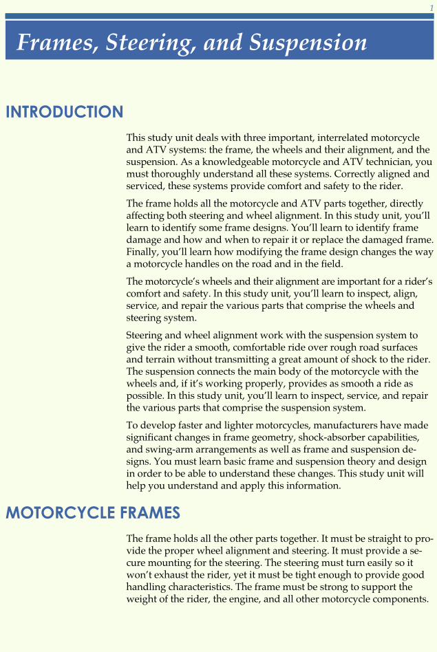
INTRODUCTIONThis study unit deals with three important, interrelated motorcycleand ATV systems: the frame, the wheels and their alignment, and thesuspension. As a knowledgeable motorcycle and ATV technician, youmust thoroughly understand all these systems. Correctly aligned andserviced, these systems provide comfort and safety to the rider.
The frame holds all the motorcycle and ATV parts together, directlyaffecting both steering and wheel alignment. In this study unit, you’lllearn to identify some frame designs. You’ll learn to identify framedamage and how and when to repair it or replace the damaged frame.Finally, you’ll learn how modifying the frame design changes the waya motorcycle handles on the road and in the field.
The motorcycle’s wheels and their alignment are important for a rider’scomfort and safety. In this study unit, you’ll learn to inspect, align,service, and repair the various parts that comprise the wheels andsteering system.
Steering and wheel alignment work with the suspension system togive the rider a smooth, comfortable ride over rough road surfacesand terrain without transmitting a great amount of shock to the rider.The suspension connects the main body of the motorcycle with thewheels and, if it’s working properly, provides as smooth a ride aspossible. In this study unit, you’ll learn to inspect, service, and repairthe various parts that comprise the suspension system.
To develop faster and lighter motorcycles, manufacturers have madesignificant changes in frame geometry, shock-absorber capabilities,and swing-arm arrangements as well as frame and suspension de-signs. You must learn basic frame and suspension theory and designin order to be able to understand these changes. This study unit willhelp you understand and apply this information.
MOTORCYCLE FRAMESThe frame holds all the other parts together. It must be straight to pro-vide the proper wheel alignment and steering. It must provide a se-cure mounting for the steering. The steering must turn easily so itwon’t exhaust the rider, yet it must be tight enough to provide goodhandling characteristics. The frame must be strong to support theweight of the rider, the engine, and all other motorcycle components.
Frames, Steering, and Suspension
1
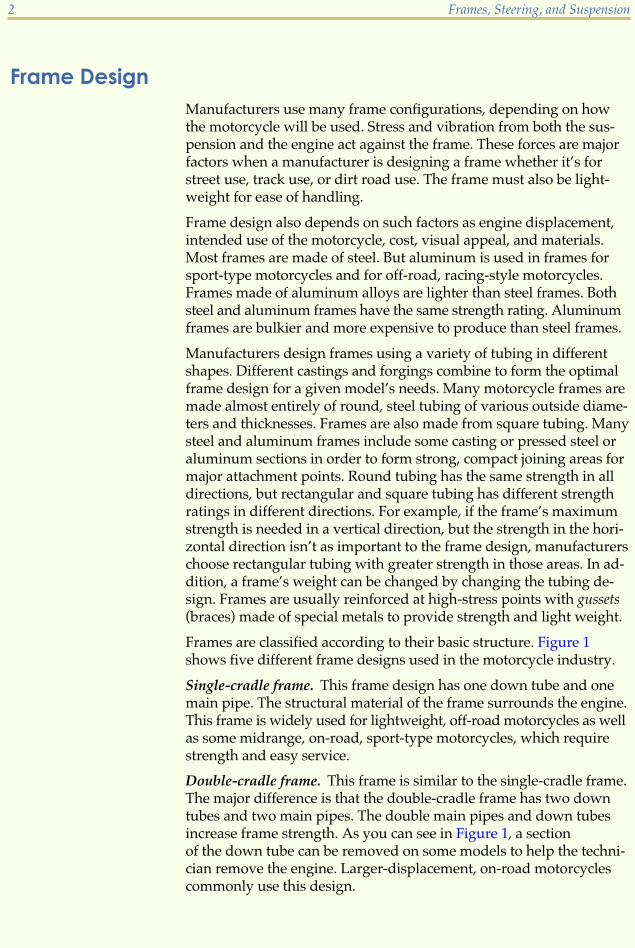
Frame DesignManufacturers use many frame configurations, depending on howthe motorcycle will be used. Stress and vibration from both the sus-pension and the engine act against the frame. These forces are majorfactors when a manufacturer is designing a frame whether it’s forstreet use, track use, or dirt road use. The frame must also be light-weight for ease of handling.
Frame design also depends on such factors as engine displacement,intended use of the motorcycle, cost, visual appeal, and materials.Most frames are made of steel. But aluminum is used in frames forsport-type motorcycles and for off-road, racing-style motorcycles.Frames made of aluminum alloys are lighter than steel frames. Bothsteel and aluminum frames have the same strength rating. Aluminumframes are bulkier and more expensive to produce than steel frames.
Manufacturers design frames using a variety of tubing in differentshapes. Different castings and forgings combine to form the optimalframe design for a given model’s needs. Many motorcycle frames aremade almost entirely of round, steel tubing of various outside diame-ters and thicknesses. Frames are also made from square tubing. Manysteel and aluminum frames include some casting or pressed steel oraluminum sections in order to form strong, compact joining areas formajor attachment points. Round tubing has the same strength in alldirections, but rectangular and square tubing has different strengthratings in different directions. For example, if the frame’s maximumstrength is needed in a vertical direction, but the strength in the hori-zontal direction isn’t as important to the frame design, manufacturerschoose rectangular tubing with greater strength in those areas. In ad-dition, a frame’s weight can be changed by changing the tubing de-sign. Frames are usually reinforced at high-stress points with gussets(braces) made of special metals to provide strength and light weight.
Frames are classified according to their basic structure. Figure 1shows five different frame designs used in the motorcycle industry.
Single-cradle frame. This frame design has one down tube and onemain pipe. The structural material of the frame surrounds the engine.This frame is widely used for lightweight, off-road motorcycles as wellas some midrange, on-road, sport-type motorcycles, which requirestrength and easy service.
Double-cradle frame. This frame is similar to the single-cradle frame.The major difference is that the double-cradle frame has two downtubes and two main pipes. The double main pipes and down tubesincrease frame strength. As you can see in Figure 1, a sectionof the down tube can be removed on some models to help the techni-cian remove the engine. Larger-displacement, on-road motorcyclescommonly use this design.
2 Frames, Steering, and Suspension

Frames, Steering, and Suspension 3
FIGURE 1—Five motorcycle frame designs are shown here. (Copyright by American Honda Motor Co., Inc, and reprinted
with permission)
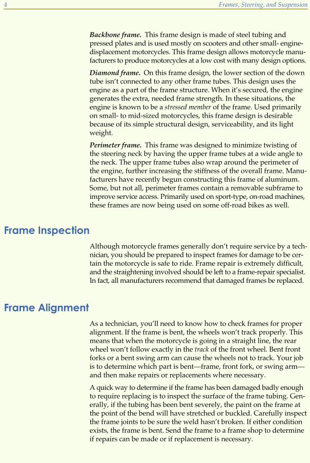
Backbone frame. This frame design is made of steel tubing andpressed plates and is used mostly on scooters and other small- engine-displacement motorcycles. This frame design allows motorcycle manu-facturers to produce motorcycles at a low cost with many design options.
Diamond frame. On this frame design, the lower section of the downtube isn‘t connected to any other frame tubes. This design uses theengine as a part of the frame structure. When it’s secured, the enginegenerates the extra, needed frame strength. In these situations, theengine is known to be a stressed member of the frame. Used primarilyon small- to mid-sized motorcycles, this frame design is desirablebecause of its simple structural design, serviceability, and its lightweight.
Perimeter frame. This frame was designed to minimize twisting ofthe steering neck by having the upper frame tubes at a wide angle tothe neck. The upper frame tubes also wrap around the perimeter ofthe engine, further increasing the stiffness of the overall frame. Manu-facturers have recently begun constructing this frame of aluminum.Some, but not all, perimeter frames contain a removable subframe toimprove service access. Primarily used on sport-type, on-road machines,these frames are now being used on some off-road bikes as well.
Frame InspectionAlthough motorcycle frames generally don’t require service by a tech-nician, you should be prepared to inspect frames for damage to be cer-tain the motorcycle is safe to ride. Frame repair is extremely difficult,and the straightening involved should be left to a frame-repair specialist.In fact, all manufacturers recommend that damaged frames be replaced.
Frame AlignmentAs a technician, you’ll need to know how to check frames for properalignment. If the frame is bent, the wheels won’t track properly. Thismeans that when the motorcycle is going in a straight line, the rearwheel won’t follow exactly in the track of the front wheel. Bent frontforks or a bent swing arm can cause the wheels not to track. Your jobis to determine which part is bent—frame, front fork, or swing arm—and then make repairs or replacements where necessary.
A quick way to determine if the frame has been damaged badly enoughto require replacing is to inspect the surface of the frame tubing. Gen-erally, if the tubing has been bent severely, the paint on the frame atthe point of the bend will have stretched or buckled. Carefully inspectthe frame joints to be sure the weld hasn’t broken. If either conditionexists, the frame is bent. Send the frame to a frame shop to determineif repairs can be made or if replacement is necessary.
4 Frames, Steering, and Suspension

If the paint or weld doesn’t show damage and you still suspect thatthe frame is bent, remove all the parts from the frame and inspect ityourself. The parts you’ll remove include the fuel tank, seat, fairing,wiring, etc. At this point, you’ll still save time and trouble by sendingthe frame to a specialist because you must have special tools to inspectand repair a damaged motorcycle frame.
Tools NeededIf you choose to go ahead and inspect the frame yourself, the toolsyou’ll need are
� Engineer’s checking table (a table that has a smooth, flat surfaceapproximately 4 feet by 6 feet)
� Adjustable-height gauge (preferably the Vernier type)
� Two or more V-blocks
� Square
� Some large C-clamps
� Set of head-pipe bearing races
� Bar that fits the internal hole of the bearing races
ProceduresThe procedures in this study unit are general in nature and not in-tended to be used for actual disassembly and repair. Their purpose isto familiarize you with the types of activities you’ll encounter. Alwaysrefer to the appropriate motorcycle or ATV service guide for mainte-nance information. The service guide contains all the information to dothe job correctly, including detailed instructions for the specific makeand model of motorcycle or ATV, special tools, and service tips. Aboveall, the service guide contains the appropriate safety information.
Checking for a Bent Front SectionFollow these steps to check for a bent front section (Figure 2):
1. Set the frame on its side on the table.
2. Insert the bearing races, bearings, and bar into the head pipe.
3. Block the head pipe with the V-block so the centerline of the baris parallel with the table. The centerline is an imaginary linedrawn through the center of the tube or pipe.
4. Block the top frame pipe so the centerline of the pipe is at thesame height from the table as the centerline of the bar throughthe head pipe.
5. Use the adjustable-height gauge to check that the parts of theframe are parallel.
Frames, Steering, and Suspension 5
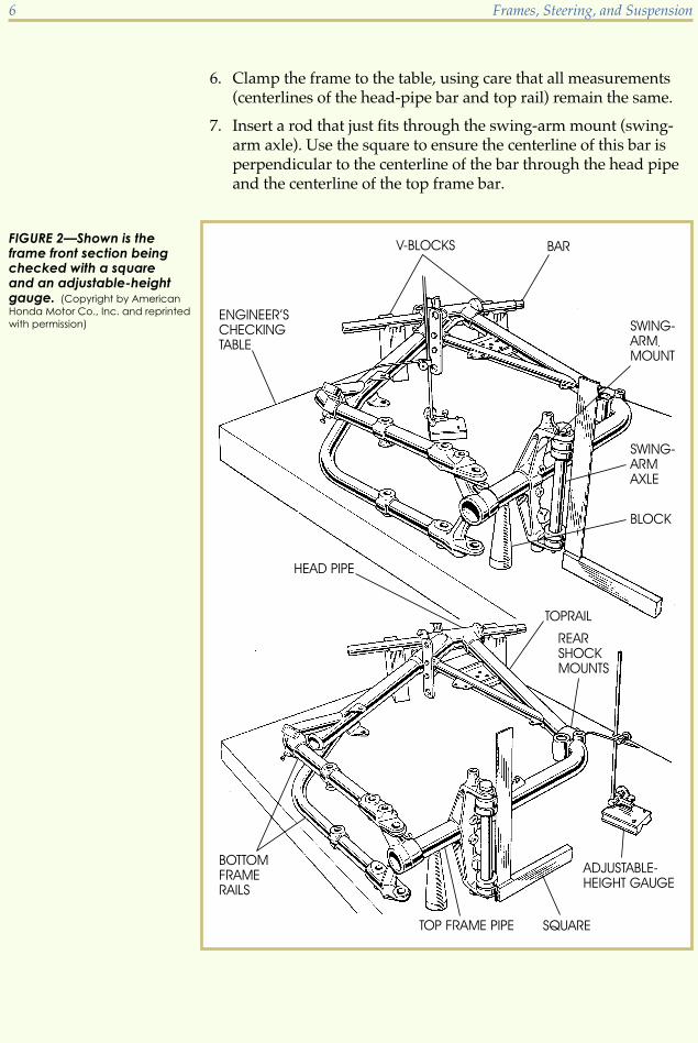
6. Clamp the frame to the table, using care that all measurements(centerlines of the head-pipe bar and top rail) remain the same.
7. Insert a rod that just fits through the swing-arm mount (swing-arm axle). Use the square to ensure the centerline of this bar isperpendicular to the centerline of the bar through the head pipeand the centerline of the top frame bar.
6 Frames, Steering, and Suspension
FIGURE 2—Shown is theframe front section beingchecked with a squareand an adjustable-heightgauge. (Copyright by American
Honda Motor Co., Inc. and reprinted
with permission)

If you find that the centerline of the bar through the swing arm isn’tperpendicular to the centerline of the bar through the head pipe, theframe is bent. Usually this bend will be in the front frame section. Aframe-repair specialist must straighten it, or you must replace thedamaged frame with a new one.
Checking for a Bent Rear SectionTo check for a bent rear frame section, position and clamp the frameso the centerline of the bottom frame rails is parallel to the tabletop.Locate the exact center of the space between the two top frame rails atthe rear shock mounts. An imaginary line drawn from one rear shockabsorber to the other should cross the top rail centerline at a 90� angle.
The holes for mounting the motorcycle parts must be at specified an-gles and distances. These specifications aren’t usually in the factory-supplied shop manual, and they’re quite complex. That’s why werecommend you have a frame-repair specialist do this type of repair.
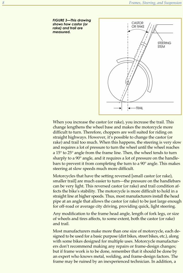
Frame ModificationsYou may encounter a chopper, which is a motorcycle with a modifiedframe. A major part of chopping the motorcycle’s frame consists ofchanging the angle of the head-pipe joint where it attaches to the topframe rail and the front-frame down tube. Changing the angle of thesetube joints changes the angle of the steering-stem axis in relation tothe ground. This angle is called the steering castor (or rake) (Figure 3).Changing the angle of the head-tube joint also changes the steeringtrail. Trail is a word used to identify the distance along the groundbetween an imaginary vertical line through the center of the front axleto the ground and another line through the center of the steering stemto the ground.
Changing both the castor (or rake) and trail directly affects both steeringease and the stability of the motorcycle. Often, motorcycles that havebeen chopped also have the length of the front-fork tubes increased.This is usually done in conjunction with changing the head-pipe angle.
Frames, Steering, and Suspension 7
When you increase the castor (or rake), you increase the trail. Thischange lengthens the wheel base and makes the motorcycle moredifficult to turn. Therefore, choppers are well suited for riding onstraight highways. However, it’s possible to change the castor (orrake) and trail too much. When this happens, the steering is very slowand requires a lot of pressure to turn the wheel until the wheel reachesa 15� to 25� angle from the frame line. Then, the wheel tends to turnsharply to a 90� angle, and it requires a lot of pressure on the handle-bars to prevent it from completing the turn to a 90� angle. This makessteering at slow speeds much more difficult.
Motorcycles that have the setting reversed [small castor (or rake),smaller trail] are much easier to turn—the pressure on the handlebarscan be very light. This reversed castor (or rake) and trail condition af-fects the bike's stability. The motorcycle is more difficult to hold in astraight line at higher speeds. Thus, most manufacturers install the headpipe at an angle that allows the castor (or rake) to be just large enoughfor off-road or average city driving, providing quick, light steering.
Any modification to the frame head angle, length of fork legs, or sizeof wheels and tires affects, to some extent, both the castor (or rake)and trail.
Most manufacturers make more than one size of motorcycle, each de-signed to be used for a basic purpose (dirt bikes, street bikes, etc.), alongwith some bikes designed for multiple uses. Motorcycle manufactur-ers don’t recommend making any repairs or frame-design changes;but if frame work is to be done, remember that it should be done byan expert who knows metal, welding, and frame-design factors. Theframe may be ruined by an inexperienced technician. In addition, a
8 Frames, Steering, and Suspension
FIGURE 3—This drawingshows how castor (orrake) and trail aremeasured.

dangerous situation may be created if the frame isn’t correctly alignedor repaired.
Road Test 1
At the end of each section of Frames, Steering, and Suspension, you’ll be asked to check yourunderstanding of what you’ve just read by completing a “Road Test.” Writing the answers tothese questions will help you review what you’ve learned so far. Please complete Road Test 1now.
1. What is a gusset on a motorcycle frame?
2. Name five factors manufacturers consider when designing motorcycle frames.
3. True or False? Frames made of aluminum alloys are lighter than steel frames, but bothhave the same strength rating.
4. Name the frame design that has only one frame down tube.
5. Name the frame design that’s made up of a combination of steel tubing and pressedplates.
6. Explain the centerline of the frame.
Check your answers with those on page 63.
MOTORCYCLE WHEEL ALIGNMENTCorrect alignment and adjustment of the steering, wheels, and frameare vital for the comfort and safety of the motorcyclist. It’s necessarythat you, the motorcycle technician, understand the importance ofthese adjustments and make a conscientious effort to be certain themotorcycle you’re working on is properly aligned.
Motorcycle wheel alignment depends on four things:
� Front-fork alignment
� Swing-arm alignment
� Wheel-axle alignment
� Steering alignment
Frames, Steering, and Suspension 9
If you observe that the wheels aren’t aligned, you should inspect thefront forks and swing arm to determine if they’re straight. These partsgenerally bend before the frame does, and they’re easier to check thanthe frame. Severely bent forks should be replaced. Therefore, unlessyou can see obvious frame damage, be sure the forks and swing armare straight before you begin the job of checking the frame.
Front-Fork Alignment
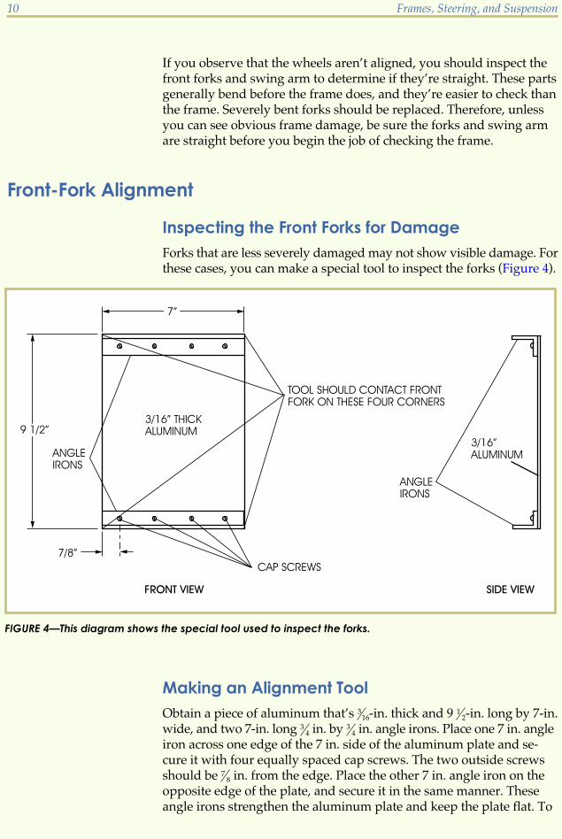
Inspecting the Front Forks for DamageForks that are less severely damaged may not show visible damage. Forthese cases, you can make a special tool to inspect the forks (Figure 4).
Making an Alignment ToolObtain a piece of aluminum that’s 3
16-in. thick and 9 12-in. long by 7-in.
wide, and two 7-in. long 34 in. by 3
4 in. angle irons. Place one 7 in. angleiron across one edge of the 7 in. side of the aluminum plate and se-cure it with four equally spaced cap screws. The two outside screwsshould be 7
8 in. from the edge. Place the other 7 in. angle iron on theopposite edge of the plate, and secure it in the same manner. Theseangle irons strengthen the aluminum plate and keep the plate flat. To
10 Frames, Steering, and Suspension
FIGURE 4—This diagram shows the special tool used to inspect the forks.

make this tool adjustable, drill holes through the aluminum plate sothe angle irons are positioned parallel to each other at various distancesapart. You can also cut hand holes as illustrated in Figure 5 to make iteasy to hold.
Checking the Front Forks for DamageTo check the front forks for damage, remove the front wheel, fender,and other front-end components. Reinstall the axle in its proper posi-tion. Hold the tool shown in Figure 5 firmly against the front of thelower fork leg. If the forks are straight, all four corners of the angleiron will contact the forks. If the tool doesn’t make contact at all fourcorners, you’ll know that the forks aren’t straight. To remedy this,loosen the fork-stem pinch bolt and the top-lug pinch bolt or cap nut.Use a soft mallet to tap the top lug sharply. This will cause the inner-fork stanchions to rotate slightly and align if they aren’t severely bent.
Frames, Steering, and Suspension 11
FIGURE 5—A special toolis being used to checkthe alignment of thefront forks. The Xs markthe corners where thetool must contact theforks.
Check the alignment again with your tool. Tap the top lug in the correctdirection until the forks align. Finally, tighten all bolts and recheck tobe sure the pressure on the pinch bolt didn’t cause distortion. If anyone of the four corners of the tool has more than 1
64 in. clearance be-tween the angle iron and the fork leg, the inner-fork tube or stem andcrown may be bent.
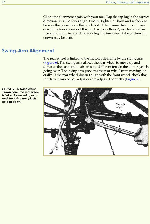
Swing-Arm AlignmentThe rear wheel is linked to the motorcycle frame by the swing arm(Figure 6). The swing arm allows the rear wheel to move up anddown as the suspension absorbs the different terrain the motorcycle isgoing over. The swing arm prevents the rear wheel from moving lat-erally. If the rear wheel doesn’t align with the front wheel, check thatthe drive chain or belt adjusters are adjusted correctly (Figure 7).
12 Frames, Steering, and Suspension
FIGURE 6—A swing arm isshown here. The rear wheelis linked to the swing arm,and the swing arm pivotsup and down.

Inspecting the Swing ArmIf the rear-wheel alignment is correct, but the rear wheel still doesn’talign with the front wheel, you must remove the rear wheel and dis-connect the rear-suspension system. Place the motorcycle on a standthat holds it in a level and upright position. Be certain the motorcycleis level by measuring the distance from the floor to each side of therear swing-arm bearing housing where it mounts to the frame. Thedistance should be equal on each side if the motorcycle is level withthe floor. Remove the rear-wheel assembly and rear-suspension sys-tem. Place the axle bolt in the axle mount and brace the swing arm inits normal position by placing a block under the bolt. Due to the factthat the rear-suspension system has been removed, the swing armwill fall to the floor without the brace. Now, measure the distance be-tween the floor and each side of the swing arm at the bottom of the
Frames, Steering, and Suspension 13
FIGURE 7—Chain adjust-ers must be properlyadjusted to ensureproper rear-wheelalignment.

axle-mounting holes. The distance should be equal on each side, indi-cating that the two sides of the swing arm are parallel and the swingarm isn’t bent. If the swing arm is bent, it must be replaced.
Wheel-Axle AlignmentCorrect wheel-axle alignment requires that the technician be sure thewheels are installed both parallel and perpendicular to the centerlineof the frame.
Imagine a line that runs directly through the center of the front fork tothe center of the space between the rear swing arm. This is the center-line of the frame. Each wheel must be aligned so that the middle ofthe wheel is positioned on this centerline of the frame. Now imagineanother line from the frame centerline directly to the ground. Eachwheel must be parallel to this line.
Align the wheels by adjusting the position of the axle in its mounts.Normally, the front forks have only one way the axle can be mounted,and the axle is in the correct position if the forks and axle are straight.
The rear wheel can be mounted incorrectly if one side of the axle isadjusted forward of the other side. In this case, the wheel wouldn’t beparallel with the frame and would cause the tire, chain, and sprocketto wear rapidly. This may also cause the steering to pull to the sidebecause the rear wheel isn’t following the front wheel (or tracking).To remedy this, the technician adjusts the position of the rear-wheelaxle. This adjustment check was explained earlier in this study unitand illustrated in Figure 7.
The perpendicular alignment of both the front and rear wheels isnecessary because a wheel that’s slanted turns in the direction of theslant. This causes tires to wear off-center and causes the steering topull to one side or the other. Swing arms that have one bent side willcause the rear wheel to slant.
Steering AlignmentThe steering-stem bearings, positioned in the frame head pipe, mustbe lubricated and have the correct amount of play to allow easy turn-ing of the front forks. Too-tight pressure on the bearings causes hard,notchy turning of the handlebars, creating incorrect steering align-ment. Conversely, too-loose pressure causes handlebar vibration.Either condition results in an unstable motorcycle.
14 Frames, Steering, and Suspension

Checking for Steering Bearing AdjustmentTo check for steering bearing adjustment, you must raise the frontwheel from the floor. Place a stand under the engine or under thelower frame. Push the handlebars lightly to either side. If the handle-bars continue moving with their own momentum, the steering isn’t tootight. Stand in front of the motorcycle and grasp the bottom of eachfork leg at the axle. Try to move the fork leg back and forth. If you canfeel any fork-stem assembly movement, the stem bearings are too loose.
Adjusting Steering TensionTo adjust steering tension, turn the steering-stem head nut. Some mo-torcycles use a locked-cap nut that must be loosened before the headnut can be turned. Tightening the steering-stem head nut increasesbearing pressure and provides harder steering. Loosen the head nutto obtain lighter steering.
Road Test 2
1. True or False? The front and rear wheels of the motorcycle must be positioned on thecenterline.
2. If one side of the rear-wheel axle adjuster is adjusted more forward than the other, whatproblems can result from this misalignment of the rear wheel?
3. If you want to remove unwanted steering stem/fork movement, first adjust the _______ toattempt to cure the problem.
4. True or False? If the steering-stem bearings of the motorcycle are too loose, handlebarvibration may result.
5. The two areas of the motorcycle that you should check first if the wheels aren’t aligned arethe_______ and the _______.
6. The rear wheel is linked to the motorcycles frame by the _______.
Check your answers with those on page 63.
Frames, Steering, and Suspension 15

MOTORCYCLE SUSPENSION SYSTEMSSuspension systems allow motorcycle wheels to roll over irregularroad surfaces while transmitting a minimum amount of shock intothe frame. The main parts of the suspension system are
� Front fork
� Rear fork (or swing arm)
� Rear shock absorbers (or rear cushion)
We’ll begin by discussing the front fork. Incorporated into the front-fork assembly are the front shock absorbers. We’ll discuss the rearfork and rear shock absorbers later in this study unit.
Telescopic Front-Suspension SystemsToday’s motorcycles, for the most part, use a telescoping, fork-typefront suspension. Some early motorcycles used spring-loaded swingarms mounted on stationary tubes to absorb bumps in the road surface.
The front-fork suspension supports the front wheel and allows it topivot from side to side for steering by means of a triple clamp, steer-ing head, and stem. Inside the fork tube are one or two springs heldin place by a fork cap and fork-slider damping rod. The triple clampholds the steering damper, if one is included.
Most front forks incorporate telescopic hydraulic shock absorbers toabsorb the vertical shock of the front wheel when hitting bumps, thusproviding a smooth ride (Figure 8). This telescopic motorcycle front-suspension system has been designed to contain a pair of upper-forktubes containing lower-fork sliders that move into one another. Insideeach of the telescopic forks is a spring and a damping-rod system.
Hydraulic damping is obtained by the transference of oil trapped be-tween the inner- and outer-fork tubes through small holes drilled inthe inner-fork tube. Some motorcycles use other valve or orifice ar-rangements to control the transfer of oil, restricting slider movement.Check the service manual to see what type of arrangement is beingused for the particular kind of motorcycle you’re working on.
The telescopic front-suspension system cushions the shock of the frontwheel hitting bumps in road surfaces. As the wheel hits a bump, thesliders are pushed upward over the inner-fork tubes and compressthe springs. The oil in the outer-fork tube flows through the holes orvalves into the inner-fork tube. Since the transfer of oil into the inner-fork tube takes up space, trapped air is compressed and the increasedair pressure increases oil-flow resistance. This has a damping effect onthe shock and limits the upward movement of the outer-fork tubes.As the shock load is relieved, the springs push the slider back to the
16 Frames, Steering, and Suspension
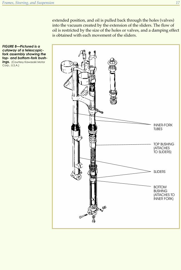
extended position, and oil is pulled back through the holes (valves)into the vacuum created by the extension of the sliders. The flow ofoil is restricted by the size of the holes or valves, and a damping effectis obtained with each movement of the sliders.
Frames, Steering, and Suspension 17
FIGURE 8—Pictured is acutaway of a telescopic-fork assembly showing thetop- and bottom-fork bush-ings. (Courtesy Kawasaki Motor
Corp., U.S.A.)

ComponentsWe’ll now look at the individual parts of the front-suspension system,starting with the steering stem.
Steering Stem (or Lower Triple Tree)The steering stem supports the right and left inner-fork tubes (or stan-chions) by clamping around them. The stem has an axle or steeringshaft in the center, mounted through bearings into the frame head.The bearings allow the stem to turn, which provides steering. Figure 9shows a typical steering stem.
Crown (or Top Triple-Tree Clamp)The crown (Figure 10) attaches around the stem axle using a clampand/or securing nut. The crown also attaches to the top of eachinner-fork tube by a cap nut that provides a solid, secure attachmentof the inner-fork tubes. The crown also serves as a mounting brace forthe handlebars.
18 Frames, Steering, and Suspension
FIGURE 9—The steeringcolumn and its componentparts are shown here.(Copyright by American Honda
Motor Co., Inc. and reprinted with
permission)

Inner-Fork TubesThe outside of the inner-fork tubes is machined to provide a smoothsurface for the bushing (bearing) and oil seal to slide over. The inner-fork tubes serve as a guide and mount for the outer-fork tubes. Figure11 shows a cutaway view of a front fork.
Outer-Fork Tubes (or Sliders or Lower Fork Legs)The outer-fork tubes (Figure 11) attach to the wheel axle and move upand down over the inner-fork tubes.
Frames, Steering, and Suspension 19
FIGURE 10—A steeringcrown and its componentparts are shown here.(Copyright by American Honda
Motor Co., Inc. and reprinted with
permission)
Fork BushingsEach side of the front fork has a top bushing and a bottom bushing.The top bushing fits around the inner-fork tube and into the top of theouter-fork tube. This bushing is held securely in the outer-fork tubeby a retaining ring or seal-holding nut. The top bushing slides up anddown with the outer-fork tube. The bottom bushing (bearing) is heldsecurely onto the inner-fork tube by a retaining ring or nut and slidesup and down inside the outer-fork tube. Figure 8 shows where thefork bushings are located.
20 Frames, Steering, and Suspension
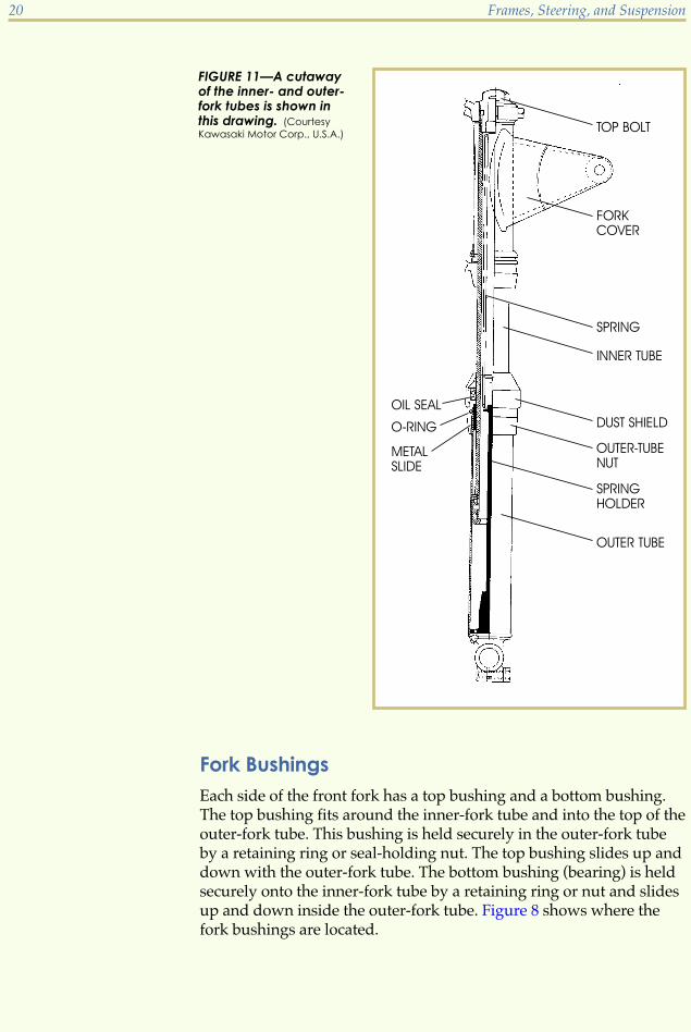
FIGURE 11—A cutawayof the inner- and outer-fork tubes is shown inthis drawing. (Courtesy
Kawasaki Motor Corp., U.S.A.)

Fork Oil SealThe fork seal, held in the top of the outer-fork tube, must fit snuglyaround the inner-fork tube because its function is to prevent oil leak-age. In addition, many motorcycles have dust seals to help protect theoil seals. Figure 11 shows the location of these components. Whilesome fork oil seals can be pried out with a screwdriver, removal andreplacement usually requires a special tool. Refer to the manufactur-er’s service manual for this information. Use care when replacingseals, as they must not be damaged during installation. Generally it’snot possible to remove fork seals from their holders without damag-ing them; therefore, new seals must be used for reassembly.
Fork SpringsFork springs extend the forks and allow movement of the outer-forktubes. Fork springs fit inside the inner-fork tube and press against thetube cap nut at one end and the outer-fork tube at the other end.Again, Figure 11 shows an example of this type of spring.
Inverted-Fork DesignThe inverted cartridge-fork assembly is basically an upside-down forkthat has a cartridge within it that operates very similarly to a cartridgedamper-fork system (Figure 12). The upper tubes in the inverted-forkdesign have a greater diameter than those of the standard right-side-up fork system. This larger upper tube gives this fork design moresurface area, which increases the front fork’s resistance to unwantedfork flexing.
Frames, Steering, and Suspension 21
FIGURE 12—An Inverted Cartirdge Fork Assembly
Hydraulic Damping UnitsVarious systems hold hydraulic damping units in place. Two examplesof typical systems follow.
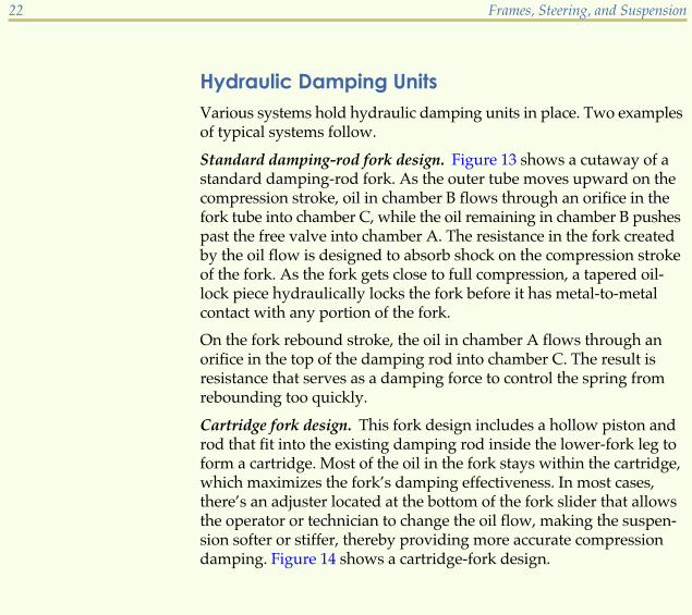
Standard damping-rod fork design. Figure 13 shows a cutaway of astandard damping-rod fork. As the outer tube moves upward on thecompression stroke, oil in chamber B flows through an orifice in thefork tube into chamber C, while the oil remaining in chamber B pushespast the free valve into chamber A. The resistance in the fork createdby the oil flow is designed to absorb shock on the compression strokeof the fork. As the fork gets close to full compression, a tapered oil-lock piece hydraulically locks the fork before it has metal-to-metalcontact with any portion of the fork.
On the fork rebound stroke, the oil in chamber A flows through anorifice in the top of the damping rod into chamber C. The result isresistance that serves as a damping force to control the spring fromrebounding too quickly.
Cartridge fork design. This fork design includes a hollow piston androd that fit into the existing damping rod inside the lower-fork leg toform a cartridge. Most of the oil in the fork stays within the cartridge,which maximizes the fork’s damping effectiveness. In most cases,there’s an adjuster located at the bottom of the fork slider that allowsthe operator or technician to change the oil flow, making the suspen-sion softer or stiffer, thereby providing more accurate compressiondamping. Figure 14 shows a cartridge-fork design.
22 Frames, Steering, and Suspension

Frames, Steering, and Suspension 23
FIGURE 13—A damping-rodfork cutaway is shownhere. (Copyright by American
Honda Motor Co., Inc. and reprinted
with permission)
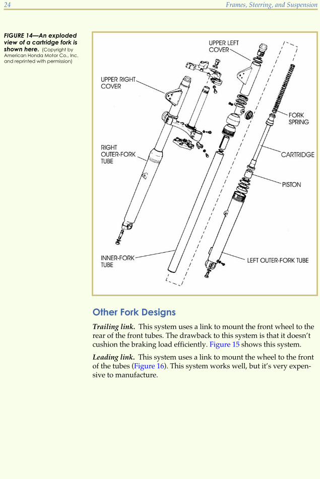
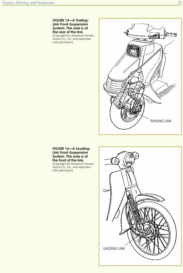
Other Fork DesignsTrailing link. This system uses a link to mount the front wheel to therear of the front tubes. The drawback to this system is that it doesn’tcushion the braking load efficiently. Figure 15 shows this system.
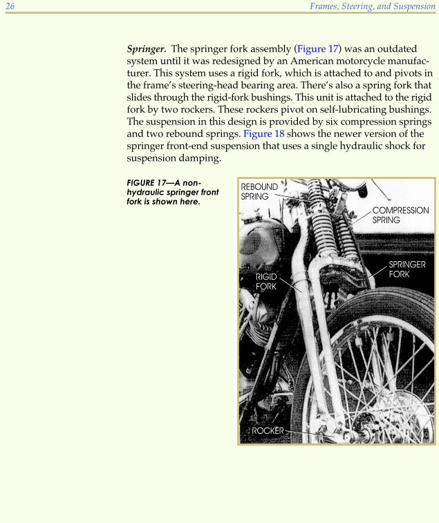
Leading link. This system uses a link to mount the wheel to the frontof the tubes (Figure 16). This system works well, but it’s very expen-sive to manufacture.
24 Frames, Steering, and Suspension
FIGURE 14—An explodedview of a cartridge fork isshown here. (Copyright by
American Honda Motor Co., Inc.
and reprinted with permission)
Frames, Steering, and Suspension 25
FIGURE 15—A Trailing-Link Front-SuspensionSystem. The axle is atthe rear of the link.(Copyright by American Honda
Motor Co., Inc. and reprinted
with permission)
FIGURE 16—A Leading-Link Front-SuspensionSystem. The axle is atthe front of the link.(Copyright by American Honda
Motor Co., Inc. and reprinted
with permission)
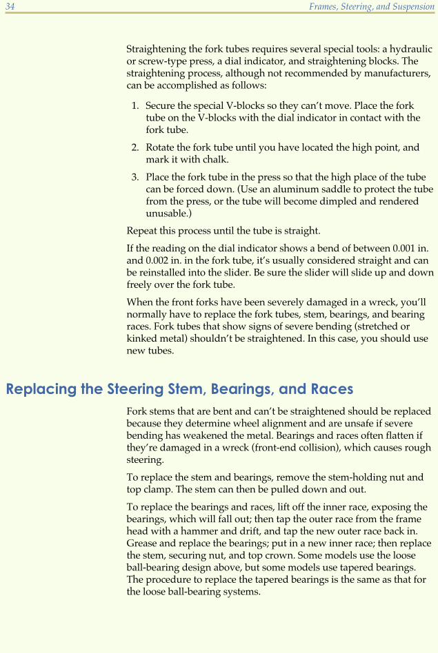
Springer. The springer fork assembly (Figure 17) was an outdatedsystem until it was redesigned by an American motorcycle manufac-turer. This system uses a rigid fork, which is attached to and pivots inthe frame’s steering-head bearing area. There’s also a spring fork thatslides through the rigid-fork bushings. This unit is attached to the rigidfork by two rockers. These rockers pivot on self-lubricating bushings.The suspension in this design is provided by six compression springsand two rebound springs. Figure 18 shows the newer version of thespringer front-end suspension that uses a single hydraulic shock forsuspension damping.
26 Frames, Steering, and Suspension
FIGURE 17—A non-hydraulic springer frontfork is shown here.

Road Test 3
1. The _______ front-fork system is the most commonly used system on motorcycles.
2. Hydraulic damping in a telescopic suspension system is obtained by the transference of_______ trapped between the inner- and outer-fork tubes through small holes drilled inthe inner-fork tube.
3. The _______ is the component that supports the right and left inner-fork tubes byclamping around them.
4. _______ and _______ are two names that are used to identify outer-fork tubes.
5. The _______ is the component located in the top of the outer-fork tube that’s used toprevent oil leakage.
Check your answers with those on page 63.
Frames, Steering, and Suspension 27
FIGURE 18—Shown here is anewer springer suspensionsystem with a hydraulicdamper in front of thesprings.

INSPECTING AND SERVICING FRONT FORKSFront-fork assembly repair and service is one job you’ll encounter oftenwhen working as a motorcycle technician. Although these assembliesare designed for long use with minimum maintenance service, forksoften need to be repaired or replaced.
Oil leaks. Normally front forks don’t require service unless the oil hasbecome contaminated or is leaking. Replace the seal when you see oilleaking. Other evidence of oil leaks is a heavy knock when the fork isfully depressed rapidly. The slider hitting the bottom of the stanchioncauses this noise.
The rapid return of the sliders to their fully extended position afterbeing fully depressed is another indication that the forks need service.This usually produces a knocking noise which indicates the quantityof oil isn‘t correct.
Contaminated oil. Although the oil is sealed in the forks andshouldn’t escape, the continued use of the fork system contaminatesthe oil. Oil that’s contaminated appears emulsified, aerated, or lightbrown in color and should be replaced because it can cause wear ofinternal parts.
Changing Fork OilThe following steps will help you learn how to change the front-forkoil:
1. Remove the drain plugs with a wrench (Figure 19). This allowsthe contaminated oil to escape.
2. Remove the fork-tube cap nut at the top of the fork tube (Figure 20).
3. Work the fork assembly up and down until all the oil has drainedfrom both fork legs.
4. Replace the drain plug.
5. Refill each side with the correct amount and viscosity of oil.
6. Replace the top cap nut.
Refer to your service manual for the correct amount and viscosity ofoil. Changing the viscosity and the amount of oil allows a softer orharder ride, as desired. A lighter-viscosity oil (2.5-weight, for example)flows through the valves faster, allowing the forks to depress morerapidly and produce a softer ride. Heavy oil, such as 10-, 15-, or20-weight, produces stiffer fork action and a harder ride. In this way,you can adjust the overall hydraulic-damping action to your preference.
28 Frames, Steering, and Suspension

Replacing the Fork SealYou must disassemble the front fork to replace a leaking oil seal. Toremove the front wheel, remove the axle-securing nut or nuts. Differ-ent systems of securing the front axle are used on different types of
the front axle. In this system, a nut on the outside of the slider holdsthe axle. After the securing nut has been removed, the axle can easilybe pulled from the wheel.
Frames, Steering, and Suspension 29
FIGURE 19—Drain plugscan be removed from thefork using a wrench.
FIGURE 20—A technician isremoving the fork-tubecap nut.
motorcycles. Figures 21 and 22 show one common method of securing

In the system shown in Figure 23, caps on the end of the sliders holdthe axle and are removed to release the axle. This system doesn’t re-quire the axle to be removed from the wheel except to service thebrakes or wheel bearings. Instead, the entire wheel assembly, includingthe axle, is removed when you want to work on the front fork.
Remove the front fender or fork braces which may be attached to bothfork sliders. At this point, you‘ll have each slider free of the other, andeach can be worked up and down independently. Remove the fork-tube cap nut (Figure 20) and the bolt securing the fork tube into thefork stem (Figure 24).
30 Frames, Steering, and Suspension
FIGURE 21—One commonmethod of attaching thefront axle to the fork isshown here.
FIGURE 22—The front axleslides out of the fork afterthe axle nut has beenremoved.

At this point, you may be able to pull the fork tube free of the stem.Figure 25 shows the fork tube. If you aren’t able to remove the forktube, obtain the factory tool designed for this purpose. This tool isnormally a long, threaded rod that has the same thread as the cap nuton one end. The cap-nut-threaded end of the tool screws into the forktube and is used to force the tube free of the stem clamp. This tool isalso used to pull the fork tube into place when you reassemble thefork.
Frames, Steering, and Suspension 31
FIGURE 23—Two attachingnuts and a cap apparatushold the axle in place.
FIGURE 24—The lower fork-stem attaching fastener isbeing removed here.

Remove the fork oil-seal holder to separate the fork tube and the slider.Again, different systems are used to secure the seal. Use the servicemanual for the particular motorcycle to help you determine whatsystem is used on your model. Two types of oil-seal holders aredescribed below.
Threaded fork slider. In this system, used on older motorcycles,the threads may be inside or outside of the fork slider or seal holder.Removal requires a special tool, as shown in your shop manual.
Snap ring. This system of holding the fork oil seal consists of a snapring that fits into a groove in the slider and is removed by snap-ringpliers as shown in Figure 26.
Straightening Bent Fork TubesAt this point in your process of repairing and servicing the frontforks, you should check to be sure that each fork tube is straight. Todetermine whether or not the fork tubes are straight, use a dial indica-tor and special blocks to allow the fork tube to be rotated (Figure 27).
32 Frames, Steering, and Suspension
FIGURE 25—The fork tubehas been removed fromthe steering stem.

Frames, Steering, and Suspension 33
FIGURE 26—This illustrationshows the removal of asnap ring which is holdingthe fork seal in place.(Copyright by American Honda
Motor Co., Inc. and reprinted with
permission)
FIGURE 27—Shown is thetechnique of measuringthe fork tube runout byrotating the fork tubewith a dial indicatormounted against it. (Copyright
by American Honda Motor Co., Inc.
and reprinted with permission)
Straightening the fork tubes requires several special tools: a hydraulicor screw-type press, a dial indicator, and straightening blocks. Thestraightening process, although not recommended by manufacturers,can be accomplished as follows:
1. Secure the special V-blocks so they can’t move. Place the forktube on the V-blocks with the dial indicator in contact with thefork tube.
2. Rotate the fork tube until you have located the high point, andmark it with chalk.
3. Place the fork tube in the press so that the high place of the tubecan be forced down. (Use an aluminum saddle to protect the tubefrom the press, or the tube will become dimpled and renderedunusable.)
Repeat this process until the tube is straight.
If the reading on the dial indicator shows a bend of between 0.001 in.and 0.002 in. in the fork tube, it’s usually considered straight and canbe reinstalled into the slider. Be sure the slider will slide up and downfreely over the fork tube.
When the front forks have been severely damaged in a wreck, you’llnormally have to replace the fork tubes, stem, bearings, and bearingraces. Fork tubes that show signs of severe bending (stretched orkinked metal) shouldn’t be straightened. In this case, you should usenew tubes.
Replacing the Steering Stem, Bearings, and RacesFork stems that are bent and can’t be straightened should be replacedbecause they determine wheel alignment and are unsafe if severebending has weakened the metal. Bearings and races often flatten ifthey’re damaged in a wreck (front-end collision), which causes roughsteering.
To replace the stem and bearings, remove the stem-holding nut andtop clamp. The stem can then be pulled down and out.
To replace the bearings and races, lift off the inner race, exposing thebearings, which will fall out; then tap the outer race from the framehead with a hammer and drift, and tap the new outer race back in.Grease and replace the bearings; put in a new inner race; then replacethe stem, securing nut, and top crown. Some models use the looseball-bearing design above, but some models use tapered bearings.The procedure to replace the tapered bearings is the same as that forthe loose ball-bearing systems.
34 Frames, Steering, and Suspension
Road Test 4
1. A fork can have a bend of between _______ to _______ inches to be considered useable andnot need to be replaced.
2. A _______ and a _______ are two special tools that are used to check a fork tube forstraightness.
3. Name the parts that will usually have to be replaced if the forks are damaged in afront-end collision.
4. Explain why a damaged fork stem should be replaced.
5. Can you vary the amount of oil in the front fork tubes?
6. How would changing the weight of the oil affect motorcycle ride?
Check your answers with those on page 63.
MOTORCYCLE REAR SUSPENSION
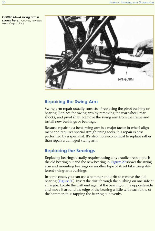
Swing-Arm AssemblyThe swing arm is mounted to the frame by a pivot shaft (or pivot bolt)which prevents side-to-side movement while at the same time allow-ing up-and-down movement of the open end (Figure 28). The swingarm works with the rear damper units (shock absorbers) to provide asmooth ride.
The swing arm serves as the mounting bracket for the rear-wheelassembly and the rear shock absorbers. The rear shock absorbers (orrear cushion) on most motorcycles aren’t rebuildable. However, someshock absorbers sold as replacement units can be rebuilt, but eventhey require a specialist. Replace rather than repair excessively wornor damaged shock absorbers.
Frames, Steering, and Suspension 35
Repairing the Swing ArmSwing-arm repair usually consists of replacing the pivot bushing orbearing. Replace the swing arm by removing the rear wheel, rearshocks, and pivot shaft. Remove the swing arm from the frame andinstall new bushings or bearings.
Because repairing a bent swing arm is a major factor in wheel align-ment and requires special straightening tools, this repair is bestperformed by a specialist. It’s also more economical to replace ratherthan repair a damaged swing arm.
Replacing the BearingsReplacing bearings usually requires using a hydraulic press to pushthe old bearing out and the new bearing in. Figure 29 shows the swingarm and mounting bearings on another type of street bike using dif-ferent swing-arm bushings.
In some cases, you can use a hammer and drift to remove the oldbearing (Figure 30). Insert the drift through the bushing on one side atan angle. Locate the drift end against the bearing on the opposite sideand move it around the edge of the bearing a little with each blow ofthe hammer, thus tapping the bearing out evenly.
36 Frames, Steering, and Suspension
FIGURE 28—A swing arm isshown here. (Courtesy Kawasaki
Motor Corp., U.S.A.)

Frames, Steering, and Suspension 37
FIGURE 29—The swing-armpivot bolt and all the bear-ings for a typical swing armare shown here. (Drawing
courtesy Triumph)
FIGURE 30—Old swing-arm bearings are oftenremoved with a hammerand a drift. (Drawing courtesy
Triumph)

New bearings are pressed into the housing with a press. Use care tobe sure the bearing starts squarely into the housing. Misalignmentcauses a burr on the bearing or possibly damages the housing.
Repairing a Bent Swing ArmStraightening a bent swing arm that has been dented at the point ofthe bend isn’t recommended. The safest and quickest repair is gener-ally replacement. However, you can use the following procedure tocheck the alignment of the rear fork.
1. Secure the motorcycle on a stand in a level, upright position.
2. Measure the distance from the floor to each side of the rear-forkbearing housing where it mounts to the frame to be certain themotorcycle is level. The distance should be equal on each side ifthe motorcycle is level with the floor.
3. Remove the rear wheel and disconnect the rear shocks.
4. Place the axle in the axle mount and brace the swing arm in itsnormal position by placing a block under the bolt. Because theshocks are disconnected, the swing arm will fall to the floor with-out a brace.
5. Measure the distance between the floor and each side of the armat the bottom of the axle-mounting hole. The distance should beequal on each side, indicating that the two sides of the swing armare parallel and the swing arm isn’t bent.
6. If one side is lower, place a bar under the low side and over thehigh side. Then apply pressure to the bar in order to bend thehigh side down, thus aligning both sides so they’re equidistantfrom the floor. If the swing arm has been removed from theframe, check alignment as shown in Figure 31.
Removing and Replacing the Swing ArmRemoving and replacing the swing arm is generally a straightforwardjob. A long bolt (spindle) with a nut holds the swing arm in the frame.Removal of the rear wheel, brake arm, and chain, along with rear en-gine mounts or other parts that may interfere with extracting the longbolt, is normally all that’s required. In some cases, this bolt and swingarm can be extracted without removing any parts except the rear-wheelcomponents, shocks, etc.
Replacing the swing arm on the frame is a reversal of the removalprocess. Place the spindle (long bolt) through the mounts and swing-arm bearings and secure with a nut before installing the other parts(shocks, rear wheel, etc.).
38 Frames, Steering, and Suspension
Rear-Damper DesignsAs we mentioned before, rear shock absorbers are usually replaced allin one unit. However, you should know how they operate and alsohow to check the condition of these shocks.
The most popular rear dampers (or shocks) on motorcycles today arethe deCarbon shock design. This shock uses nitrogen gas in a separatechamber to keep the oil in the shock from foaming. Foaming causesthe shock to lose its damping qualities.
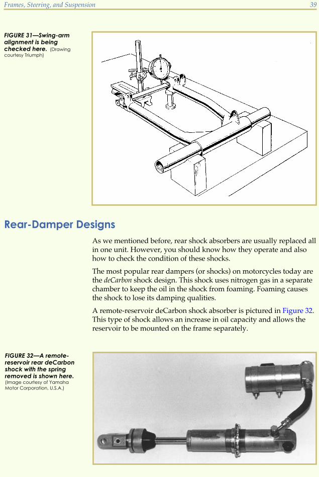
A remote-reservoir deCarbon shock absorber is pictured in Figure 32.This type of shock allows an increase in oil capacity and allows thereservoir to be mounted on the frame separately.
Frames, Steering, and Suspension 39
FIGURE 31—Swing-armalignment is beingchecked here. (Drawing
courtesy Triumph)
FIGURE 32—A remote-reservoir rear deCarbonshock with the springremoved is shown here.(Image courtesy of Yamaha
Motor Corporation, U.S.A.)

A piggyback deCarbon shock absorber is pictured in Figure 33. Thisshock has the same internal design as the remote-reservoir shock buthas its reservoir mounted solidly onto the shock body.
The oil in the deCarbon shock is normally controlled by spring washersthat are forced to move when the oil pushes them open as the shock iscompressed. Figure 34 shows the shock piston rod after it has beendisassembled. Figure 35 shows a close-up view of the piston rod to al-low us to view the shims on the bottom of the rod. These shims move,allowing the oil to flow through the shock. Figure 36 shows the shockfurther disassembled so we can see the shims as they’re removed inorder. Damping characteristics can be changed by moving these shimsinto different positions. This type of work is recommended for experi-enced shock-absorber professionals only!
40 Frames, Steering, and Suspension
FIGURE 33—A piggybackrear deCarbon shock withthe spring removed isshown here.
FIGURE 34—A typicalshock piston rod is shownhere. Note the nut whichholds the componentstogether.

To do a simple check of the condition of a rear deCarbon shock, re-move it from the motorcycle and compress each shock absorber. Ifthe shock absorber, when released, returns halfway to the originalposition quickly and then slowly the rest of the way, it’s in good con-dition. If it returns quickly all the way to its original position, the shockabsorber probably needs to be replaced.
Motorcycle Rear-Suspension SystemsMotorcycle suspension-system technology, especially in rear suspen-sions (single-shock models in particular), has advanced considerablyover the past decade. Twin-shock rear suspensions are still widelyused, but single-shock models have become the industry standard.Motorcycle technicians should understand how they work.
Frames, Steering, and Suspension 41
FIGURE 35—Here is aclose-up view of theshock piston rod.
FIGURE 36—Pictured is afully disassembled rearshock piston rod.
There are five basic types of modern motorcycle single-shock rear-suspension systems:
� Monocross (Yamaha)
� Uni-Trak (Kawasaki)
� Pro-Link (Honda)
� Full-Floater (Suzuki)
� Paralever (BMW)
You should know that all five of these systems operate on the principleof rising rate. When a rider drives over small bumps and at lowspeeds, the first third of the rear suspension travel is engineered toensure a smooth, comfortable ride. Then, as the rider hits larger bumpsor the speed of the bike increases, the suspension becomes progres-sively stiffer to resist bottoming. This is known as rising rate suspension.Let’s look at the five single-shock systems now in more detail.
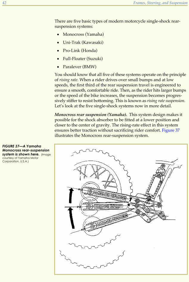
Monocross rear suspension (Yamaha). This system design makes itpossible for the shock absorber to be fitted at a lower position andcloser to the center of gravity. The rising-rate effect in this systemensures better traction without sacrificing rider comfort. Figure 37illustrates the Monocross rear-suspension system.
42 Frames, Steering, and Suspension
FIGURE 37—A YamahaMonocross rear-suspensionsystem is shown here. (Image
courtesy of Yamaha Motor
Corporation, U.S.A.)

Uni-Trak suspension (Kawasaki). This system is designed to transferthe movement of the motorcycle’s rear wheel and swing arm to aspecially-designed link arm which in turn acts upon one large shockabsorber and spring assembly. This shock-absorber assembly is lo-cated low and in the center of the rear end of the frame. This designimproves weight centralization by lowering the motorcycle center ofgravity. As the suspension is compressed, the design of the shock’slinkage increases the shock’s damping and spring rate progressively.This means that when the motorcycle hits big holes, the rider gets alot of shock damping; and when the motorcycle hits small holes, therider gets very light shock damping. Figure 38 illustrates the Uni-Trakrear-suspension system.
Pro-Link suspension (Honda). The Pro-Link rear-suspension systemis designed to give the rear-suspension system a rising rate as theswing-arm movement reaches its full compression. The linkage de-sign of this system acts like a fulcrum on a teeter-totter in your localplayground. The fulcrum moves forward and backward as the swingarm swings from full extension to full compression. At full extension,the fulcrum is near the swing-arm pivot, which in turn gives the rearwheel a lot of leverage over the shock. The ride is very smooth over
Frames, Steering, and Suspension 43
FIGURE 38—A KawasakiUni-Trak suspension isshown here. (Courtesy
Kawasaki Motor Corp., U.S.A.)
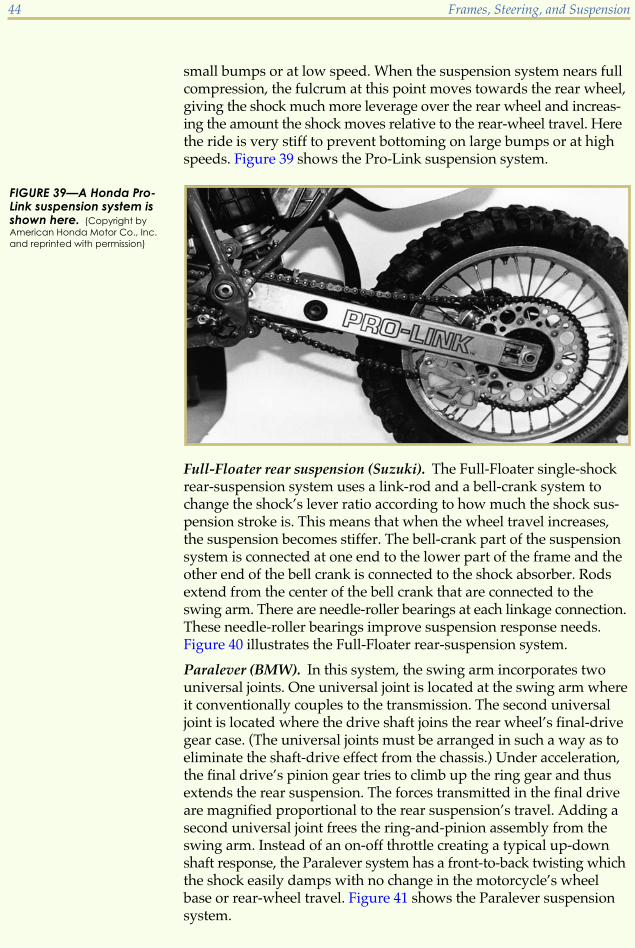
small bumps or at low speed. When the suspension system nears fullcompression, the fulcrum at this point moves towards the rear wheel,giving the shock much more leverage over the rear wheel and increas-ing the amount the shock moves relative to the rear-wheel travel. Herethe ride is very stiff to prevent bottoming on large bumps or at highspeeds. Figure 39 shows the Pro-Link suspension system.
Full-Floater rear suspension (Suzuki). The Full-Floater single-shockrear-suspension system uses a link-rod and a bell-crank system tochange the shock’s lever ratio according to how much the shock sus-pension stroke is. This means that when the wheel travel increases,the suspension becomes stiffer. The bell-crank part of the suspensionsystem is connected at one end to the lower part of the frame and theother end of the bell crank is connected to the shock absorber. Rodsextend from the center of the bell crank that are connected to theswing arm. There are needle-roller bearings at each linkage connection.These needle-roller bearings improve suspension response needs.Figure 40 illustrates the Full-Floater rear-suspension system.
Paralever (BMW). In this system, the swing arm incorporates twouniversal joints. One universal joint is located at the swing arm whereit conventionally couples to the transmission. The second universaljoint is located where the drive shaft joins the rear wheel’s final-drivegear case. (The universal joints must be arranged in such a way as toeliminate the shaft-drive effect from the chassis.) Under acceleration,the final drive’s pinion gear tries to climb up the ring gear and thusextends the rear suspension. The forces transmitted in the final driveare magnified proportional to the rear suspension’s travel. Adding asecond universal joint frees the ring-and-pinion assembly from theswing arm. Instead of an on-off throttle creating a typical up-downshaft response, the Paralever system has a front-to-back twisting whichthe shock easily damps with no change in the motorcycle’s wheelbase or rear-wheel travel. Figure 41 shows the Paralever suspensionsystem.
44 Frames, Steering, and Suspension
FIGURE 39—A Honda Pro-Link suspension system isshown here. (Copyright by
American Honda Motor Co., Inc.
and reprinted with permission)

Rear-Suspension MaintenanceWith proper factory-recommended maintenance performed at sched-uled intervals, very little service and few repairs are necessary on today’smodern motorcycle rear suspensions. Perhaps the most importantmaintenance factor—aside from maintaining the motorcycle’s gas, oil,and air levels—is the proper lubrication of all moving parts (greasingthe rods, links, bushings, joints, etc.) of the rear-suspension assembly.
Frames, Steering, and Suspension 45
FIGURE 40—The SuzukiFull-Floater rear-suspensionsystem is shown here.(Courtesy of American Suzuki
Motor Corporation)
FIGURE 41—The BMWParalever suspensionsystem is shown here.(Courtesy of BMW of North
America, Inc.)

Road Test 5
1. A _______ is used to mount the motorcycle’s swing arm to the frame.
2. Rebuilding the swing arm usually consist of replacing the _______ or _______.
3. Is straightening a bent swing arm recommended?
4. Name the five types of motorcycle rear-suspension systems that use a single shock.
5. Match each suspension-system design from item # 4 to its motorcycle manufacturer.
Check your answers with those on page 64.
ATV FRAME AND SUSPENSION SYSTEMS
ATV FramesATV frames and chassis, although different in shape from motorcycleframes and chassis, are constructed of the same types of materials. Aswith motorcycle frames, not much repair or maintenance is necessary.If an ATV frame becomes bent or cracked, a frame-repair specialistshould replace or repair it. Shown in Figure 42 is an exploded viewof a typical 3-wheel ATV frame and chassis. A typical 4-wheel ATVframe is shown in Figure 43.
46 Frames, Steering, and Suspension

Frames, Steering, and Suspension 47
FIGURE 42—An exploded view of a typical 3-wheel ATV frame is shown here. (Courtesy Kawasaki Motor Corp.,
U.S.A.)
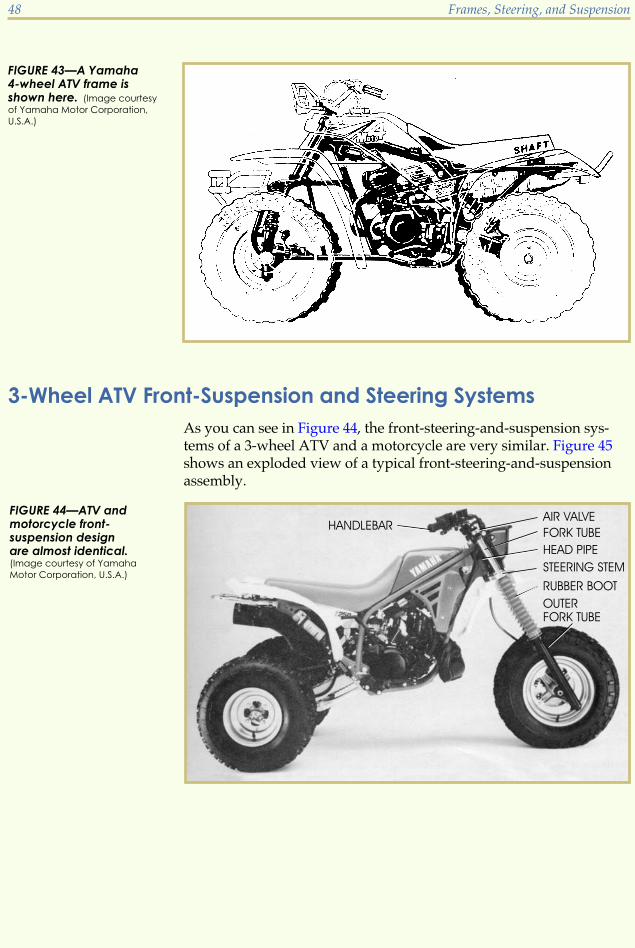
3-Wheel ATV Front-Suspension and Steering SystemsAs you can see in Figure 44, the front-steering-and-suspension sys-tems of a 3-wheel ATV and a motorcycle are very similar. Figure 45shows an exploded view of a typical front-steering-and-suspensionassembly.
48 Frames, Steering, and Suspension
FIGURE 43—A Yamaha4-wheel ATV frame isshown here. (Image courtesy
of Yamaha Motor Corporation,
U.S.A.)
FIGURE 44—ATV andmotorcycle front-suspension designare almost identical.(Image courtesy of Yamaha
Motor Corporation, U.S.A.)
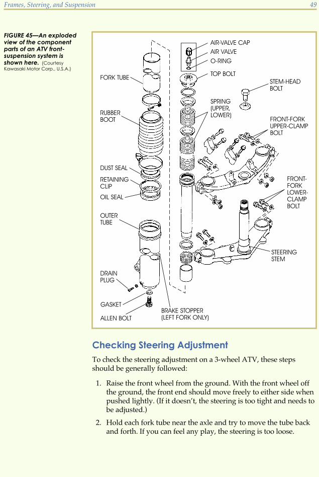
Checking Steering AdjustmentTo check the steering adjustment on a 3-wheel ATV, these stepsshould be generally followed:
1. Raise the front wheel from the ground. With the front wheel offthe ground, the front end should move freely to either side whenpushed lightly. (If it doesn’t, the steering is too tight and needs tobe adjusted.)
2. Hold each fork tube near the axle and try to move the tube backand forth. If you can feel any play, the steering is too loose.
Frames, Steering, and Suspension 49
FIGURE 45—An explodedview of the componentparts of an ATV front-suspension system isshown here. (Courtesy
Kawasaki Motor Corp., U.S.A.)

Adjusting SteeringTo adjust the steering on a 3-wheel ATV, follow these steps:
1. Remove the fuel tank, gauges, and headlight assembly.
2. Position a stand beneath the frame to raise the front wheel fromthe ground.
3. Loosen the four front-fork lower-clamp bolts and the steeringstem-head bolt.
4. Once these bolts are loose, use the special stem-nut wrench to ad-just the steering-stem locknut properly. If the steering is too looseor has play, tighten the locknut. If the steering is too tight, loosenthe locknut.
5. Tighten the stem locknut after it’s properly adjusted.
6. Tighten the stem-head bolt to the specified torque.
7. Use the proper amount of torque and tighten the front-fork lowerclamp bolts.
Removing and Inspecting the Steering BearingsIf the correct steering adjustment can’t be attained by the above pro-cedures, remove and inspect the steering bearings. The stem-bearingcomponents of a typical ATV are shown in Figure 46. To remove thesteering-stem bearings,
1. Remove the fuel tank, front wheel, front-fork legs, headlight unit,handlebars, stem-head bolt, and steering-stem head.
2. Remove the bearings. Use the special stem-bearing remover todrive out the upper bearing race. Use the bearing puller andadapter for the lower race.
3. Clean and examine the bearings. If they show signs of pitting,wear, or damage, replace them. Both bearing-race surfaces mustbe smooth with no signs of pitting or excessive wear.
4. Pack the bearings and races with a high-quality grease. Alwaysinspect the grease seal, located below the lower bearing. Replacethis seal any time it shows signs of wear, deterioration, ordamage.
50 Frames, Steering, and Suspension

Reinstalling the Outer-Bearing RacesTo reinstall the outer-bearing races,
1. Use the special driver-press shaft and bearing drivers to drivethe outer-bearing races into the head pipe until they stop at thestepped portion machined in the head pipe (Figure 47).
2. Use the special stem-bearing driver and adapter to install the ta-pered roller bearings on the steering stem.
3. Seat the bearings using the special stem-nut wrench.
4. Tighten the stem locknut to the specified torque.
5. Recheck the steering play and readjust, if necessary.
Frames, Steering, and Suspension 51
FIGURE 46—The steering-stem bearing compon-ents of an ATV areillustrated here. (Courtesy
Kawasaki Motor Corp., U.S.A.)

Measuring Front-Fork Oil LevelAlthough the air pressure in the front forks is usually adjustable, thefork oil should be maintained at the specified level. To measure thefront-fork oil level,
1. Expel any air in the oil by compressing the front fork. Do this bypushing down on the handlebars several times with the frontbrake fully applied.
2. Deflate the air pressure from the front-fork air valves.
3. Unscrew the top plugs and remove the main spring from eachfork leg.
4. Keeping the forks fully compressed, use a tape measure or rod tomeasure the distance from the upper edge of each fork inner tubeto the oil.
5. Compare this measurement with the factory service manualspecification.
Changing Front-Fork OilIf it’s necessary to add fork oil, be sure to use the recommendedgrade, viscosity, and amount. Oil for the front forks must be changedat factory-recommended intervals. To change front-fork oil,
52 Frames, Steering, and Suspension
FIGURE 47—The installa-tion of the steering-stembearing races using aspecial tool is shownhere. (Courtesy Kawasaki
Motor Corp., U.S.A.)
1. Deflate the front-fork air pressure.
2. Unscrew the front-fork plugs and drain the oil. Apply the frontbrake and push down on the handlebars several times to pumpout all the oil.
3. Clean the drain plugs with solvent and blow them dry with com-pressed air.
4. Apply a nonpermanent locking agent to the drain-plug threads.
5. Using new gaskets, install new drain plugs and tighten them tothe specified torque.
6. Unscrew the top plugs and remove the main springs from thefork legs.
7. Following the procedure discussed previously, refill each fork legwith the specified amount of oil.
Disassembling the ForksTo repair a bent fork tube or to replace the fork seals, the forks have tobe disassembled. To disassemble,
1. Drain each fork leg of oil.
2. Remove the front brake, front wheel, and other related compo-nents.
3. After removing each fork leg, push the inner-fork tubes in all theway.
4. Using a special Allen wrench, an extension handle, and anadapter, remove the bottom Allen bolts.
5. With the inner- and outer-fork tubes separated, remove theretaining rings and dust seals. Use the special oil-seal puller toremove the oil seals.
6. Replace the oil seals and retaining rings. It’s best to replace the oilseals and retaining rings any time the forks have been disassem-bled.
7. Install the new oil seals using the special oil-seal driver. Be sureto apply oil to the new seals before installing them.
Fork reassembly is basically the reverse of the disassembly. Be sure toapply a nonpermanent locking agent to the threads of the drain plugs,the Allen bolts, and the air valves.
Frames, Steering, and Suspension 53

4-Wheel ATV Front-Suspension and Steering SystemsFigure 48 shows a typical 4-wheel ATV front-suspension system. Themost common 4-wheel ATV front-suspension system uses pivotingcontrol arms suspended by coil-over shock absorbers. The service andrepair of coil-over shocks will be covered later in this study unit in thesection on rear suspension.
Servicing the Steering ShaftTo service the steering shaft,
1. Remove the seat, front carrier, gas tank, and front fenders.
2. Remove the handlebar cover and headlight body bracket bolts.
3. Remove the retaining ring, handlebar holder nuts, and handle-bar.
4. Flatten the lock tab and remove the guide-holder bolts.
5. Remove the steering-shaft guides and O-rings.
6. Remove the under-guard from the frame.
7. Remove the cotter pins, tie-rod ends, and steering-shaft nuts.
8. Remove the steering shaft from the frame and determine whetherit’s bent and requires replacement.
9. Replace the steering-shaft guide and O-rings, if necessary.
10. Reinsert the steering shaft into the frame.
54 Frames, Steering, and Suspension
FIGURE 48—A four-wheelATV front-suspensionsystem is shown here.(Image courtesy of Yamaha
Motor Corporation, U.S.A.)

11. If there’s any play, replace the shaft, bushings, and O-rings asrequired.
Servicing the Steering KnucklesTo service the steering knuckles of a 4-wheel ATV,
1. Remove the cotter pins and the knuckle-securing nuts.
2. Disconnect the knuckles from the frame.
3. Remove the brake-shoe plate.
4. Inspect the knuckles, thrust covers, bushings, and collar for wearor damage.
5. Insert the collar into the knuckle. If there’s any play, replace thecollar, thrust washers, and bushings as a set.
6. Check the tie-rod ends for movement or play.
7. Replace the tie-rod ends if there’s any play or a rough spot.
Reassembling the Steering SystemTo reassemble the steering system,
1. Insert the tie-rod ends into the tie-rods, as shown in Figure 49.
2. Adjust the length of the tie-rod assembly to factory specificationsby turning both tie-rod ends.
3. Apply a lithium-base grease to the thrust covers, collar, andbushings.
4. Insert the axle into the brake-shoe plate, and install the knuckleonto the frame.
5. Install the knuckle shaft, and tighten it to the proper torquespecification.
Frames, Steering, and Suspension 55
FIGURE 49—The tie-rodends have both left andright threads. (Image courtesy
of Yamaha Motor Corporation,
U.S.A.)

6. Install the tie-rod ends onto the knuckles, and torque the nuts tothe correct specification.
7. Replace all cotter pins.
Checking Tie-Rod AdjustmentOnce the steering system is reassembled, check the tie-rod adjustmentby following these steps:
1. Position the vehicle on a level surface and mark both front-tiretread centers.
2. Measure the width between the two marks.
3. Move the front tires 180° (12 of a full rotation) backward or
forward.
4. Measure the width between the two marks again.
5. Compute the toe-in measurement. To compute the toe-in measure-ment, subtract one width measurement from the other (B minus A,as shown in Figure 50). (If the toe-in isn’t 5 mm, turn both tie-rodsby the same amount until the proper specification is attained.)
6. Tighten the tie-rod locknuts to the recommended torque specifi-cation, making sure the tie-rod end heads are flush with eachother.
56 Frames, Steering, and Suspension
FIGURE 50—The measur-ing of toe-in is illustratedhere. (Image courtesy of
Yamaha Motor Corporation,
U.S.A.)
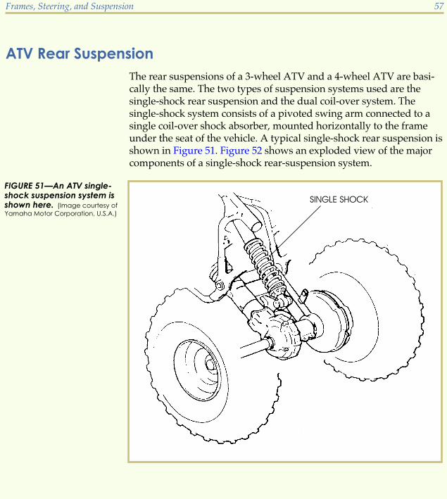
ATV Rear SuspensionThe rear suspensions of a 3-wheel ATV and a 4-wheel ATV are basi-cally the same. The two types of suspension systems used are thesingle-shock rear suspension and the dual coil-over system. Thesingle-shock system consists of a pivoted swing arm connected to asingle coil-over shock absorber, mounted horizontally to the frameunder the seat of the vehicle. A typical single-shock rear suspension isshown in Figure 51. Figure 52 shows an exploded view of the majorcomponents of a single-shock rear-suspension system.
Frames, Steering, and Suspension 57
FIGURE 51—An ATV single-shock suspension system isshown here. (Image courtesy of
Yamaha Motor Corporation, U.S.A.)

A dual coil-over rear suspension consists of a pivoting swing arm sus-pended by two coil-over shock absorbers, mounted vertically to therear of the frame. A typical dual coil-over rear suspension is shown inFigure 53. The shock-absorber rates and the coil-spring preload set-tings are adjustable on most coil-over shocks used on ATVs. There areusually four settings on the shock-absorber adjuster, with #4 being thestrongest spring force.
58 Frames, Steering, and Suspension
FIGURE 52—An exploded view of a single-shock ATV rear-suspension system is shown here. (Courtesy Kawasaki
Motor Corp., U.S.A.)

Adjusting the DamperTo adjust the damper,
1. Remove the rear fender.
2. Slide the dust cover from the top of the shock absorber.
3. Turn the damper adjuster to the desired number setting (untilyou feel a click).
Adjusting the Spring PreloadTo adjust the spring preload,
1. Remove the shock absorber from the frame by first taking off theseat and rear fender.
2. Loosen the upper and lower shock-absorber mounting nuts, butdon’t remove them.
3. Position a stand beneath the vehicle so that the rear wheels are offthe ground.
4. Remove the mounting bolts and nuts and the shock absorber.
5. Thoroughly clean the threads at the bottom of the shock absorber.
Frames, Steering, and Suspension 59
FIGURE 53—An ATVdual coil-over shocksuspension system isshown here. (Image courtesy
of Yamaha Motor Corporation,
U.S.A.)

6. Clamp the lower portion of the shock in a vise, being careful toavoid damaging it.
7. Using the special hook wrenches, loosen the locknut and turn theadjusting nut while holding the upper mounting bracket. Thespring preload becomes stronger as the adjusting nut is turnedupwards.
8. Once the proper preload is set, tighten the locknut to the specifiedtorque.
Some ATVs, as well as most off-road motorcycles, are equipped withthe deCarbon-style, gas-pressurized shock absorbers that we discussedin an earlier section of this study unit. An exploded view of a typicaldeCarbon gas shock is shown in Figure 54.
60 Frames, Steering, and Suspension
FIGURE 54—An explodedview of a deCarbon rearshock absorber on an ATVis shown here. (Courtesy
Kawasaki Motor Corp., U.S.A.)

Changing deCarbon Shock-Absorber OilA deCarbon shock absorber usually requires that the shock oil bechanged periodically. To change the oil in a gas-pressurized shockabsorber,
1. Remove the shock and reservoir from the vehicle.
2. Remove the valve cap to release the nitrogen gas.
3. Once the gas has been released, clamp the lower part of the reser-voir in a vise with aluminum soft jaws.
4. Remove the hose from the reservoir.
5. Empty the oil from the gas reservoir and shock-absorber body.
6. Refill the shock-absorber body with the specified amount of new oil
7. Bleed the air from the system by moving the shock’s piston’sshaft up and down, pushing the air bubble to the surface of theoil. Continue this action until all the air has surfaced and hasbeen removed.
8. Connect the hose to the reservoir and tighten to the proper torque.
9. Inject nitrogen gas through the valve on the gas reservoir to therecommended pressure specification.
10. Reinstall the spring and readjust the spring preload.
11. Mount the shock absorber to the vehicle.
Road Test 6
1. If the frame of an ATV becomes bent or cracked, it should be
2. When adjusting the steering on an ATV, the _______, _______, and _______ should beremoved first.
3. To remove and inspect the 3-wheeler ATV’s steering-head bearing, which componentsshould be removed?
4. Explain how to reinstall outer-bearing races into the ATV’s head pipe.
5. When servicing the steering knuckles of a 4-wheel ATV, you must first remove the_______ and the _______.
Frames, Steering, and Suspension 61
Check your answers with those on page 63.

1
1. It’s a brace that’s used to reinforce theframe at high-stress points.
2. Engine displacement, its intended use(off-road, highway only), cost, visualappeal, materials
3. True
4. Single cradle
5. Backbone
6. It’s an imaginary line that runs throughthe center of the front forks to the cen-ter of the space between the rear swingarm.
2
1. True
2. Excessive tire, chain, or sprocket wear,and the steering may pull to one sidemore than the other.
3. steering-stem head nut
4. True
5. rear-wheel alignment, front-forkstraightness
6. swing arm
3
1. telescopic
2. oil
3. steering stem
4. Slider, lower fork legs
5. fork oil seal
4
1. 0.001 in. to 0.002 in.
2. dial indicator, V-blocks
3. Fork tubes, stem, bearings, bearing races
4. The fork stem determines front-wheelalignment and is unsafe if it’s damaged.
5. Yes
6. Lighter weight produces a softer ride.Heavier weight produces a harder ride.
Road Test Answers
63

5
1. pivot shaft or pivot bolt
2. pivot bushings, bearings
3. No
4. Monocross, Uni-Track, Pro-Link,Full-Floater, Paralever
5. Yamaha, Kawasaki, Honda, Suzuki,BMW
6
1. replaced or repaired by a frame-repairspecialist.
2. fuel tank, gauges, headlight assembly
3. Fuel tank, front wheel, front-fork legs,headlight assembly, handlebars, stem-head bolt, and steering-stem head
4. Drive them in using a special driver-press shaft and bearing drivers.
5. cotter pins, knuckle-securing nuts
64 Road Test Answers

ONLINE EXAMINATION
When you’re confident that you’ve mastered the material in your studies, you cancomplete your examination online. Follow these instructions:
2. Click the Back button on your browser.3. Click the Take an Exam button near the top of the screen. 4. Type in the eight-digit examination number.
Examination
For the online exam, you must use this
EXAMINATION NUMBER:
03301600
1. Write down the eight-digit examination number shown in the box above.


![[Your Unit] MOTORCYCLE RIDER PRE-SEASON BRIEFING](https://static.fdocuments.net/doc/165x107/626beb75c346f4309945c164/your-unit-motorcycle-rider-pre-season-briefing.jpg)