STUDY TECHNOLOGY FOR VSTOL … FOR VSTOL FIGHTER/ATTACK AIRCRAFT ... Study of Aerodynamic Technology...
180
STUDY OF AERODYNAMIC TECHNOLOGY FOR VSTOL FIGHTER/ATTACK AIRCRAFT PHASE I FINAL REPORT BY HERBERT H. DRIGGERS MAY 1978 PREPARED UNDER CONTRACT NAS2-9772 BY VOUGI-IT CORPORISTIOll ~dvan~ed ~@chnoloc)q center, Inc. an CTV company FOR AMES RESEARCH CENTER NATIONAL AERONAUTICS AND SPACE ADMINISTRATION https://ntrs.nasa.gov/search.jsp?R=19790001857 2018-05-17T21:56:04+00:00Z
Transcript of STUDY TECHNOLOGY FOR VSTOL … FOR VSTOL FIGHTER/ATTACK AIRCRAFT ... Study of Aerodynamic Technology...
STUDY OF AERODYNAMIC TECHNOLOGY FOR VSTOL
FIGHTER/ATTACK AIRCRAFT PHASE I FINAL REPORT
BY HERBERT H. DRIGGERS
MAY 1978
PREPARED UNDER CONTRACT NAS2-9772 BY
VOUGI-IT CORPORISTIOll ~ d v a n ~ e d ~@chnoloc)q center, Inc. an CTV company
FOR AMES RESEARCH CENTER
NATIONAL AERONAUTICS AND SPACE ADMINISTRATION
https://ntrs.nasa.gov/search.jsp?R=19790001857 2018-05-17T21:56:04+00:00Z

'For ult by the National Tachnical lnformrtim Servtce. Sprlngfleld, Vlrglnta 22161
I. Repat No 2. Government Accau~on No.
NASA CR- 1 521 32 4. Tttle and Subtitle
Study o f Aerodynamic Technology f o r VSTOL F igh te r /A t tack A i r c r a f t - Phase I F i n a l Report
7 Authorlsl
Herbert H. Dr iggers
9. k f a m t n g Organiulion Name and Address
Vought Corpora t ion Advanced Technology Center Da l las , Texas 75222
12 Sponsoring Agency Name and Address
NASA, Ames Research Center, M o f f e t t F i e l d , CA 94035 David Tay lo r Naval Ship Re earch and Development
Center, Bethesda, MD 20084 15 Supplementary Notes
3 Rutpient's Catalog No
5 Report Date
May 1978 6. Performinp Orwntzat~on
8 Performtnp Organrzatton Report No
10 Work Un~t No
11 Contract or Grant No
Contract NAS2-9?72 13 Type of Repon and Period Covered
Contract !4ov 77 - Hay 78 ,
14 Sponsoring Agency codc
Anes Research Center Technical Moni tor - W. P. Nelms (415) 965-5855
DTNSRDC Po in t o f Contact - R. L. Schaeffer (202) 227-1180
16 Abstract
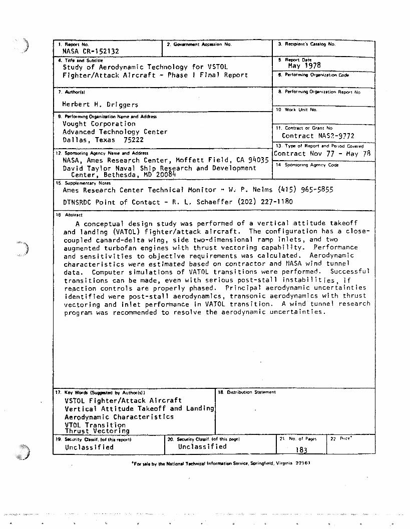
A conceptual design study was performed o f a v e r t i c a l a t t i t u d e t a k e o f f and land ing (vAToL) f i g h t e r / a t t a c k a i r c r a f t . The c o n f i g u r a t i o n has a c lose- coupled canard-del ta wing, s ide two-dimensional ramp i n l e t s , and two augmented turbofan engines w i t h t h r u s t vec to r i ng c a p a b i l i t y . Performance and s e n s i t i v i t i e s t o o b j e c t i v e requirements was ca l cu la ted . Aerodynamic c h a r a c t e r i s t i c s were est imated based on con t rac to r and NASA wind tunnel data. Computer s imu la t ions o f VATQL t r a n s i t i o n s were performed. Successful t r a n s i t i o n s can be made, even w i t h ser ious p o s t - s t a l l i n s t a b i l i t i e s , i f r e a c t i o n c o n t r o l s a re p rope r l y phased. P r i n c i p a l aerodynamic u n c e r t a i n t i e s i d e n t i f i e d were p o s t - s t a l l aerodynamics, t ranson ic aerodynamics w i t h t h r u s t vec to r i ng and i n l e t performance i n VATOL t r a n s i t i o n . A wind tunnel research program was recommended t o reso lve the aerodynamic u n c e r t a i n t i e s .
17 Key Words (Sugpnlad by Authorlsl t
VSTOL F igh te r /A t tack A i r c r a f t V e r t i c a l A t t i t u d e Takeoff and Landing Aerodynamic C h a r a c t e r i s t i c s VTOL T r a n s i t i o n Thrust Vec tor ing
18 D~strtbut~on Statement
19 !hcurltv aassif. tot this report)
U n c l a s s i f i e d 1 1 No of Pager
183
20 Security Classif lot thts meel U n c l a s s i f i e d
2 2 Fr!re'

FOREWORD
Th is study o f VSTOL aerodynamic technology was t h e i n i t i a l phase o f a
research program j o i n t l y sponsored by the Nat ional Aeronautics and Space
Admin is t ra t i on and the Un i ted States Navy, and administered by NASA. The
Technical Moni tor was M r . W. P. Nelms o f the A i r c r a f t Aerodynamics Branch,
Ames Research Center. Navy representa t ives were M r . R. L. Schaeffer o f the
David W. Tay lor Naval Ship Research and Development Center, and M r . M. W. Brown
o f t h e Naval A i r Systems Command.
Admin is t ra t i ve manager f o r t he Vought Corporat ion, Advanced Technology
Center was D r . C. H. Haight, Manager, Aerodynamics and Propuls ion. The
P r i n c i p a l I nves t iga to r was t l r . H. H. Driggers, P ro jec t Engineer, Vought
Corporat ion, who d i rected the study.
The f o l l o w i n g Vought Employees made important c o n t r i b u t i o n s t o the
Phase I study e f f o r t :
D. D. Bender I n s t a l l e d Propuls ion Data
K. W. Higharn
R. L. Mask
Mass Proper t ies
T r a n s i t i o n Program
R. G . Musgrove Conf igura t ion Design
W. W. Rhoades I n l e t Ana lys is
S. Ronero
R. T. S t a n c i l
Aerodynamic Estimates Thrust Vector ing Analys is
Conf igurat ion Synthesis Short Takeoff Ana lys is
W. L. Straub, J r . T r a n s i t i o n Ana lys is Thrust Vector ing Analys is Research Program

CONTENTS
PAGE - AB ST RACT
FOREWORD
1.0 SUMMARY
2.0 l NTRODUCT l ON
3.0 SYMBOLS
4.0 SF-121 DESCRl PTlON
4.1 DES l GN PH l LOSOPHY
4.2 DESIGN GUIDELINES
4.2.1 Performance Gu ide l ines
4.2.2 VATOL Des i gn Cons i de r a t ions
4.3 SF-121 CONFIGURATION
5.0 AERODYNAMIC CHARACTER1 ST1 CS
5.1 LONGITUDINAL CHARACTERISTICS
5.1 .1 Minimum Drag
5.1 .2 Trimmed L i f t and Drag
5.1.3 Untrimmed L o n g i t u d i n a l C h a r a c t e r i s t i c s
5.2 LATERAL/DI RECTI ONAL AERODYNAMICS
5.2.1 Con t ro l s Neu t ra l C h a r a c t e r i s t i c s
5.2.2 Cont ro l Sur face E f f e c t i v e n e s s
6.0 PROPULS l ON
6.1 ENGINE DESCRIPTION
6.2 AIR INDUCTION SYSTEM
6 . 3 ATT ITUDE CONTROL SYSTEM
6 . 4 PERFORMANCE IN TRANS ITION
7.0 AIRCRAFT DESIGN
7.1 FLIGHT CONTROLS
7.2 STRUCTURAL DESIGN
7.2.1 Wing and Empennage
7.2.2 Fuselage
7.2.3 Fuel System
7.2.4 Landing Gear
7.2.5 I n t e r n a l Gun
7.2.6 T i l t i n g Seat
7.2.7 Ma te r ia l s
7.3 MASS PROPERTIES
8 -0 SF-1 21 PERFORMANCE
8.1 POINT DESIGN
8.1.1 Conf igura t ion Synthesis
8.1.2 Miss ion Capab i l i t y
8.1.3 Combat Performance
8.2 SENSITIVITIES
8.2.1 Wing Opt imiza t ion
8.2.2 Const ra in t Va r ia t i ons
8.3 TRANS ITION PERFORMANCE
8.3.1 Landing T r a n s i t i o n
8.3 -2 Takeoff Conversion
8.3.3 A t t i t u d e Contro l System
8.3.4 Reconversion Control Phasing
8.4 SHQRT TAKEOFF
8.5 H I G H SPEED THRUST VECTORING
8.5.1 Thrust Vector ing f o r Maneuvering
8.5.2 Thrust Vector ing f o r Supersonic Cruise
9.0 AERODYNAMIC UNCERTAINT l ES
9.1 f RANSON l C AND SUPERSON I C AERODYNAMICS
9.2 BUFFET CHARACTER1 ST l CS
9.3 TRANSITION AERODYNAMICS
9.4 INLET AERODYNAMICS
9.5 PROPULSION INDUCED EFFECTS
10.0 RESEARCH PROGRAM
PAGE - 7-2
7-3
7-3
7-3
7 -4
7 -4
CONTENTS (cONT .)
10.1 W l ND TUNNEL MODEL
10.1.1 Basel ine Model Concept
10.1.2 Model Growth Options
10.1.3 F l a t R iser Var iants
10.2 WIND TUNNEL TEST PROGRAM
10.3 METHODS DEVELOPMENT
10.3.1 Supersonic Modi f ied L inear Theory
10.3.2 Transonic Wing Opt imizat ion
10.3.3 Propuls ion Induced E f f e c t s
1 1 .0 CONCLUS IONS
12.0 REFERENCES
PAGE - 10-1
10-1
10-4
10-6
10-8
10-14
10-14
10-16
10-1 7
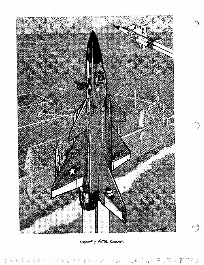
Superf l y VATOL Concept
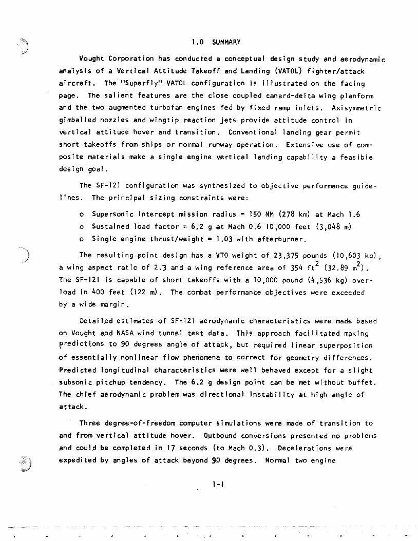
1.0 SUMMARY
Vought Corporat ion has conducted a conceptual des i gn study and aerodynamic
ana lys is o f a V e r t i c a l A t t i t u d e Takeoff and Landing ( V A T O ~ ) f i g h t e r / a t t a c k
a i r c r a f t . The "Superf ly" VATOL con f igu ra t i on i s i l l u s t r a t e d on the fac ing
page. The sa l i e n t features are the c lose coupled canard-del t a wing p lanform
and the two augmented turbofan engines fed by f i x e d ramp i n l e t s . Axisymmetric
gimbal l e d nozzles and w i n g t i p reac t ion j e t s provide a t t i t u d e con t ro l i n
v e r t i c a l a t t i t u d e hover and t r a n s i t i o n . Conventional landing gear permi t
shor t t akeo f f s from ships o r normal runway opera t ion . Extensive use o f com-
p o s i t e ma te r ia l s make a s i n g l e engine v e r t i c a l land ing c a p a b i l i t y a f e a s i b l e
design goal.
The SF-121 con f igu ra t i on was synthesized t o o b j e c t i v e performance guide-
1 ines. The p r i n c i p a l s i z i n g cons t ra in ts were:
o Supersonic In te rcep t mission radius = 150 NM (278 km) a t Mach 1.6
o Sustained load fac to r = 6.2 g a t Mach 0.6 10,000 fee t (3,048 m)
o S ing le engine th rus t /we ight = 1.03 w i t h a f te rbu rne r .
The r e s u l t i n g p o i n t design has a VTO weight o f 23,375 pounds (10,603 k g ) , 2 2 a wing aspect r a t i o o f 2.3 and a wing reference area o f 354 f t (32.89 m ) .
The SF-121 i s capable o f sho r t t akeo f f s w i t h a 10,000 pound (4,536 kg) over-
load i n 400 fee t (122 m) . The combat performance ob jec t i ves were exceeded
by a wide margin.
De ta i l ed est imates o f SF-121 aerodynamic c h a r a c t e r i s t i c s were made based
on Vought and NASA wind tunnel t e s t data. Th is approach f a c i 1 i ta ted making predict i .ons t o 90 degrees angle o f at tack, but requi red 1 inear superpos i t ion
o f e s s e n t i a l l y nonl inear flow phenomena t o co r rec t f o r geometry d i f fe rences.
Pred ic ted l o n g i t u d i n a l c h a r a c t e r i s t i c s were we1 1 behaved except f o r a s l i g h t
subsonic p i t chup tendency. The 6.2 g design p o i n t can be met w i thout b u f f e t .
The c h i e f aerodynamic problem was d i r e c t i o n a l i n s t a b i l i t y a t h igh angle o f
a t tack .
Three degree-of-freedom computer s imula t ions were made o f t r a n s i t i o n t o
and from v e r t i c a l a t t i t u d e hover. Outbound conversions presented no problems
and could be completed i n 17 seconds ( t o Mach 0.3). Decelerat ions were
expedi ted by angles o f a t tack beyond 90 degrees. Normal two engine
reconversions t o hover were general ly uncomplicated, w i t h ample t h rus t and
cont ro l power. Successful t rans i t i ons w i t h one engine (T/W = 1.03) were a lso
feasib le, but cont ro l margins were very smal I . The c r i t i c a l region i s around
50 degrees angle o f a t tack, where des tab i l i z i ng moments are h igh and th rus t
se t t i ngs are low. I
The po ten t ia l o f h igh speed th rus t vector ing was assessed. No improve-
ment i n s p e c i f i c excess power o r sustained load fac to r was found. Combined
canard f l a p de f lec t ion and th rus t vector ing was useful f o r d i r ec t 1 i f t control
and fuselage aiming. Canard l i f t was the l i m i t i n g f ac to r on TVC appl ica t ion.
P r inc ipa l aerodynamic uncer ta in t ies are high angle o f a t tack f l y i n g
qua1 i t i e s , b u f f e t charac te r i s t i cs and t ransonic aeropropulsion i n te rac t ions.
Other uncer ta in t ies pecu l ia r t o VATOL mode operations are ship wake turbulence
e f f ec t s , propuls ion induced spray and p i l o t v i s i b i l i t y requirements. A
research program was proposed around a wind tunnel model concept compatible
w i t h the XM2R compact propuls ion simulator.
The SF-121 VATOL f i g h t e r concept which i s the subject of t h i s repor t
i s a product o f a cont inuing Vought VSTOL conf igurat ion research program.
VATOL emerged as a h i gh l y promising approach t o VSTOL f i g h t e r propulsion,
o f f e r i n g exceptional performance and a simple propuls ion system.
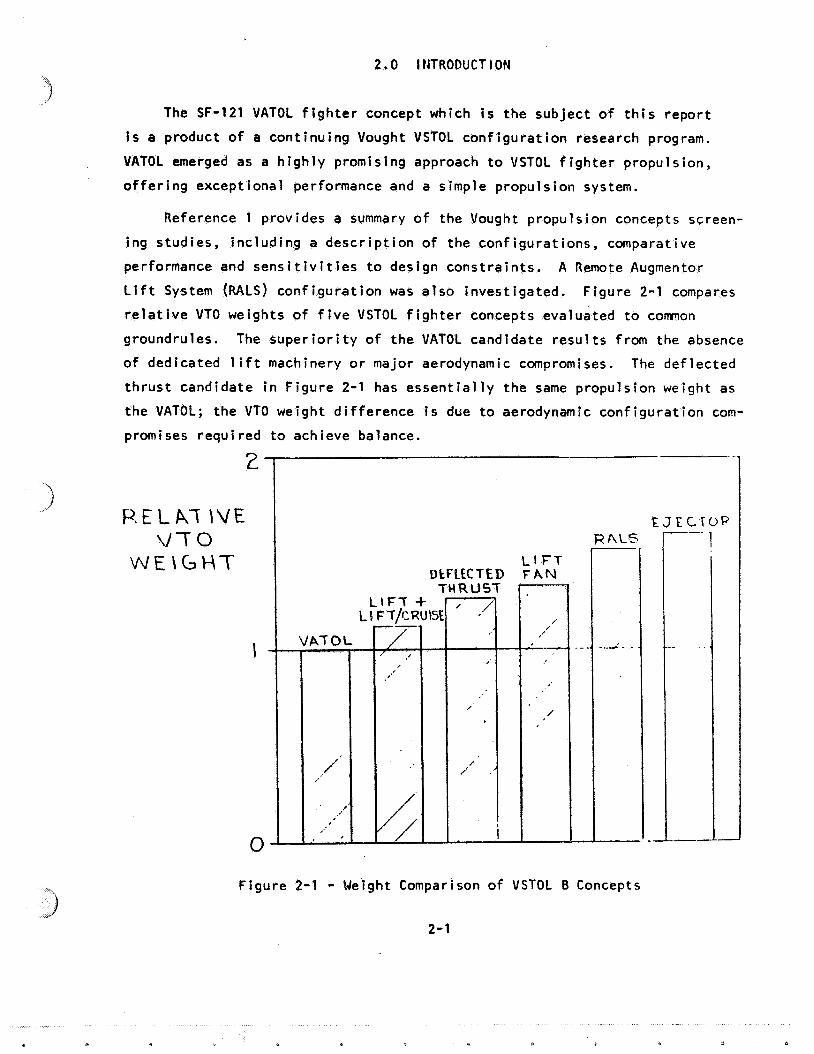
Reference 1 provides a summary o f the Vought propulsion concepts screen-
ing studies, inc lud ing a descr ip t ion o f the conf igurat ions, comparative
performance and s e n s i t i v i t i e s t o design const ra in ts . A Remote Augmentor
L i f t System (RALS) conf igurat ion was a l so investigated. Figure 2-1 compares
r e l a t i v e VTO weights o f f i v e VSTOL f i g h t e r concepts eva lu i ted t o conmon
groundrules. The supe r i o r i t y of the VATOL candidate resu l t s from the absence
o f dedicated l i f t machinery o r major aerodynamic compromises. The def lec ted
t h rus t candidate i n Figure 2-1 has essen t i a l l y the same propuls ion weight as
the VATOL; the VTO weight d i f fe rence i s due t o aerodynamic conf igurat ion con-
promises required t o achieve balance.
Figure 2-1 - Weight Comparison o f VSTOL B Concepts
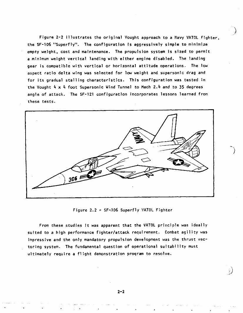
Figure 2-2 i l l u s t r a t e s the o r i g i n a l \!ought approach t o a tlavy VATOL f l g h t e r ,
the SF-106 "Superfly". The conf igurat ton I s aggressively simple t o minimize
empty weight, cost and maintenance. The propuls ion system i s sized t o permit
a minimum weight v e r t i c a l landing w i t h e i t h e r engine disabled. The landing
gear i s compatible w i t h v e r t i c a l o r ho r i zon ta l a t t i t u d e operations. The low
aspect r a t i o d e l t a wing was selected f o r l o w weight and supersonlc drag and
f o r i t s gradual s t a l l i n g charac te r i s t i cs . This con f igu ra t ion was tested i n
the Vought 4 x 4 f oo t Supersonic Wind Tunnel t o Mach 2.4 and t o 35 degrees
angle o f at tack. The SF-121 conf igurat ion Incorporates lessons learned from
these tests.
Figure 2.2 - SF--106 Superfly VATOL F ighter
From these studies i t was apparent tha t the VATOL p r i n c i p l e was i dea l l y
su i ted t o a h igh performance f igh te r /a t tack requirement. Combat a g i l i t y was
impressive and the only mandatory propuls ion development was the t h rus t vec-
t o r i n g system. The fundamental question o f operat ional s u i t a b i l i t y must
u l t ima te l y requ i re a f l i g h t demonstration proqram t o resolve.
Vought proposed the VATOL concept f o r de ta i led analysis t o the
ob jec t i ve performance guide1 i nes i n the Request f o r Proposal (~e fe rence 2).
H iss ion ro les , weapons d e f i n i t i o n and technology pro jec t ions were made by
Vought . The Phase I study ob ject ives were:
o Evaluate performance po ten t ia l of a v e r t i c a l a t t i t u d e takeof f
and landing (VATOL) f lghter /a t tack a i r c r a f t concept.
o Estimate aerodynamic charac te r i s t i cs o f the design
o netermine a b i l i t y t o t r a n s i t i o n t o and from v e r t i c a l a t t i t u d e
hover by computer s imulat ion
o Assess aerodynamic uncer ta in t ies associated w i t h the study
con f igu ra t ion and the YATOL operat ing mode
o Develop a wind tunnel research program and model concept t o
explore aerodynamic uncer ta in t ies and acquire a data base.

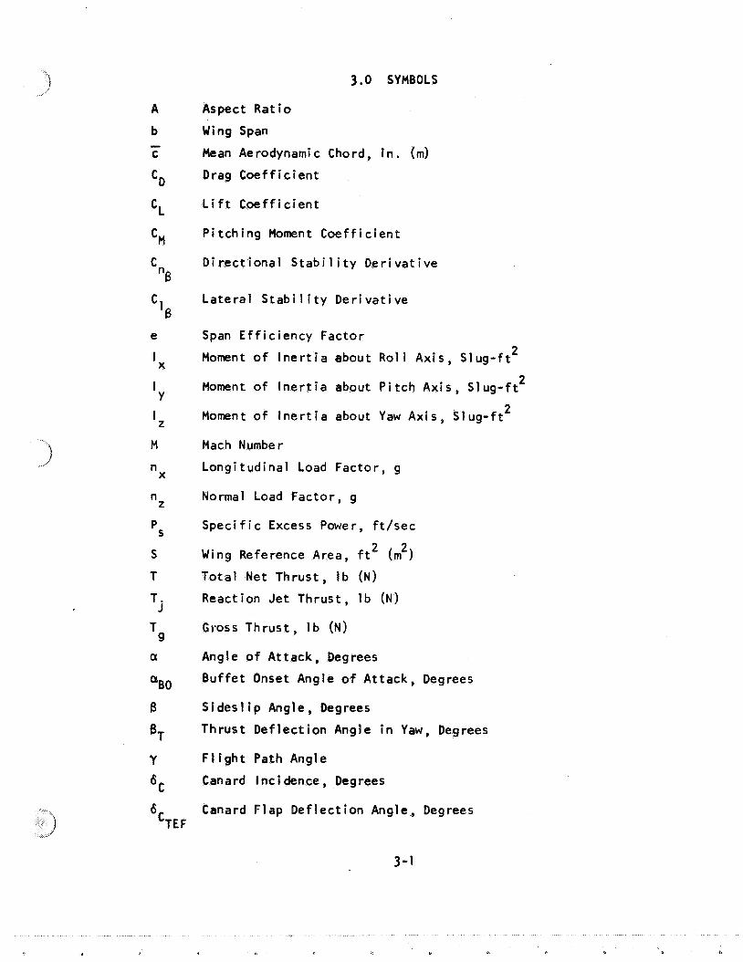
3.0 SYMBOLS
A Aspect Ra t io
b Wing Span - c Mean Aerodynamic Chord, in . (m)
C~ Drag Coef f i c ien t
L L i f t Coe f f i c ien t
M P i t ch ing Moment Coe f f i c ien t
C D i rec t iona l Stabi 1 i t y Der ivat ive
C Latera l Stabi 1 i t y Der ivat ive I@
e Span E f f i c i ency Factor
I Moment o f I n e r t i a about Ro l l Axis, S lug- f t 2 X
I Moment o f I n e r t i a about P i t ch Axis, S lug- f t 2 Y
Moment o f l n e r t i a about Yaw Axis, S lug- f t 2 I z
N Mach Number
n X
Longi tudinal Load Factor, g
n Z
Normal Load Factor, g
s Spec i f i c Excess Power, f t / sec
S Wing Reference Area, f t 2 (m 2 )
T Tota l Net Thrust, I b (N)
T j
Reaction Jet Thrust, l b (N)
T Gross Thrust , l b (N) 9
a Angle o f Attack, Degrees
a~~ Buffet Onset Angle o f Attack, Degrees
f3 Sides1 i p Angle, Degrees
6, Thrust Def lec t ion Angle i n Yaw, Degrees
Y F l i g h t Path Angle
c Canard I nc i dence , Degrees
6 Canard Flap Def lec t ion Angle, Degrees C~~ F
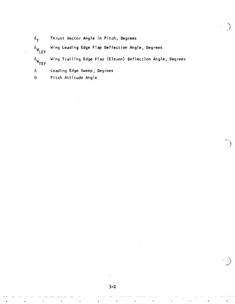
6~ Thrust Vector Angle i n P i t c h , Degrees
6 Wing Leading Edge Flap D e f l e c t i o n Angle, Degrees "LE F
6 Wing T r a i 1 ing Edge Flap (Elevon) D e f l e c t i o n Angle, Degrees 'TEF
A Lead i ng Edge Sweep, Degrees
0 P i t c h A t t i t u d e Angle
*I 4.0 SF-123 DESCRIPTION
4.-1 DES l GN PH IaLOSOPHY
The Super f ly SF-121 i s the l a t e s t o f a se r ies o f Vought h i g h performance
VSTOL f i g h t e r concepts. The SF-121 design phi losophy centers around:
o The V e r t i c a l A t t i t u d e Takeoff and Landing (VATOL) p r i n c i p l e o Normal land ing gear f o r convent ional t akeo f f and landing c a p a b i l i t y o The a b i l i t y t o make a v e r t i c a l landing on e i t h e r o f i t s two l i f t /
c r u i s e engines.
The VATOL approach o f f e r s the h ighest performance a t the lowest weight
o f a l l candidates evaluated by Vought (Reference 1). It i s a l s o a very simple
s o l u t i o n t o ach iev ing VSTOL c a p a b i l i t y ; bo th a i r f rame and propu ls ion can be ,
r e l a t i v e l y convent ional , y e t b e n e f i t f u l l y from advanced technology.
Twin engines a r e a hal lmark o f t he Super f ly concept. Some a l t e r n a t i v e
concepts r e q u i r e more than one engine f o r VTOL opera t i on and a r e doubly
vu lne rab le t o an engine f a i l u r e . VATOL i s as f e a s i b l e w i t h one o r two engines
as convent ional f i g h t e r s are; t he choice i s no t d i c t a t e d by necessi ty . Con-
'> s i d e r a t i o n s favo r ing t w i n engines f o r the SF-I21 were:
o Lower peacetime a t t r i t i o n r a t e o Fewer o p p o r t u n i t i e s t o rescue downed p i l o t w i t h dispersed forces o Higher su rv i vab i 1 i t y probable o Ease o f engine handl ing on shipboard o P r a c t i c a l L i m i t a t i o n s on engine s i z e
The phi losophy o f designing f o r a s i n g l e engine v e r t i c a l landing was
cont inued on the SF-121; otherwise any s u r v i v a b i l i t y arguments f o r tw in
engines were i nva l i da ted . The engine-out cons idera t ion i s an important one
f o r VSTOL. The e f f e c t i s t o p lace a premium on empty weight.
The SF-121 design phi losophy was in f luenced by the Phase I study ph i l os -
ophy. Th is was t o d e f i n e a bas ic c o n f i g u r a t i o n f o r in-depth ana lys i s and as
a p o i n t o f departure f o r a comprehensive wind tunnel t e s t program. To t h i s
end the con f igu ra t i on was kept "aggressively simple". The aerodynamic f i x e s
evaluated i n t h e Vought h igh speed wind tunnel tests, reported i n Reference 3 , were h e l d i n reserve f o r f u t u r e use. (This dec i s ion was re in fo rced by the
observat ion t h a t many devices which suppress s t a l l d e p a r t l ~ r e e f f e c t s cause
a more severe departure a t a h igher angle o f a t tack . ) S i m i l a r l y , a c t i v e 1 i f t
enhancement, such as spanwise blowing o r Vought's ATC wing were not considered
appropr ia te f o r a reference t e s t con f igu ra t i on , bu t cou ld be fac to red i n t o
f u t u r e t e s t programs.
4.2 DESIGN GUIDELINES
4 .2 .1 Performance Guidel ines
The Request f o r Proposal, A r t i c l e I I , l i s t s c e r t a i n o b j e c t i v e
performance gu ide l ines . These are:
o High performance VSTOL f i g h t e r / a t t a c k a i r c r a f t o Supersonic dash c a p a b i l i t y w i t h susta ined Mach number c a p a b i l i t y
o f a t l e a s t 1.6 o Operat ional from land and from ships smal ler than CVs w i thou t
ca tapu l t s and a r r e s t i n g gear (good ST0 capabi 1 i t y ) o Sustained load f a c t o r o f 6.2 a t Mach 0.6, 10,000 f o o t a l t i t u d e a t
88 percent VTOL gross weight. o S p e c i f i c excess power a t 1G ( P S ~ G ) o f 900 fps a t Mach 0.9, 10,000
f o o t a l t i t u d e a t 88 percent VTOL gross weight. o VTOL gross weight = 20,000 t o 35,000 pounds. o ST0 sea-based gross weight - VTOL gross weight p lus 10,000 pounds.
Previous VATOL s tud ies i nd i ca ted the on ly cons t ra in ing parameter would be the
sustained load fac to r , which would s i z e the wing. The a b i l i t y t o meet the
ST0 requ i rement had t o be conf i rmed.
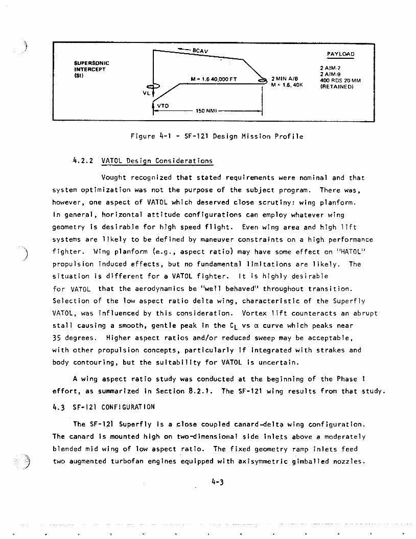
Several o the r gu ide l i nes must be s ta ted t o un ique ly de f ine a p o i n t design;
c h i e f among them a re the design miss ion p r o f i l e and radius. The miss ion most
compatible w i t h RFP gu ide l ines and the i n t r i n s i c m e r i t s o f VSTOL i s the
Supersonic In te rcep t ( ~ e c k Launched in te rcep t ) miss ion, diagrammed i n F igure 4-1.
Th is t y p i c a l rad ius o f 150 NM was selected f o r the SF-121 study. The design
miss ion es tab l ishes i n t e r n a l f u l l load. Previous Vought s tudies i n d i c a t e
t h a t good a t t a c k miss ion performance can be obta ined w i t h the DL1 miss ion
i n t e r n a l f u e l p lus ex te rna l tasks. No minimum a l t e r n a t e miss ion rad ius o r
t ime on s t a t i o n requirements were imposed f o r the sub jec t study.
One important g u i d e l i n e t o be resolved by the study was the VTOL engine
s i z i n g c o n s t r a i n t . For a s i n g l e engine con f igu ra t i on t h i s would be VTO t h r u s t /
weight, t y p i c a l l y 1.10. The t w i n engine Superf ly concept i s b e t t e r character-
ized by a one engine v e r t i c a l landing requirement, as app l i ed t o the Navy Type
A VSTOL (T/w - 1 -03).
v
PAY LOAD
SUPERSONIC INTERCEPT 2 AIM 7 (st) 2 AIM-9 2 MIN AIB 400 RDS 20 MM
M = 1.6.40K (RETAINEDI v
- F igure 4-1 - SF-121 Design Miss ion P r o f i l e
4.2.2 VATOL Desiqn Considerat ions
Vought recognized t h a t s ta ted requirements were nominal and t h a t
system o p t i m i z a t i o n was n o t the purpose o f the sub jec t program. There was,
however, one aspect o f VATOL which deserved c lose s c r u t i n y : wing planform.
I n general, h o r i z o n t a l a t t i t u d e con f i gu ra t i ons can employ whatever wing
geometry i s d e s i r a b l e f o r h igh speed f l i g h t . Even wing area and h igh l i f t
systems a r e l i k e l y t o be de f ined by maneuver c o n s t r a i n t s on a h igh performance
f i g h t e r . Wing p lanform (e.g., aspect r a t i o ) may have some e f f e c t on "HATOL"
p ropu ls ion induced e f f e c t s , b u t no fundamental l i m i t a t i o n s a re l i k e l y . The
s i t u a t i o n i s d i f f e r e n t f o r a VATOL f i g h t e r . I t i s h i g h l y des i rab le
f o r VATOL t h a t the aerodynamics be "wel l behaved" throughout t r a n s i t i o n .
Se lec t i on o f t h e low aspect r a t i o d e l t a wing, c h a r a c t e r i s t i c o f t he Superf ly
VATOL, was in f luenced by t h i s cons idera t ion . Vortex l i f t counteracts an abrupt
s t a l l causing a smooth, g e n t l e peak i n t h e CL vs a curve which peaks near
35 degrees. Higher aspect r a t i o s and/or reduced sweep may be acceptable,
w i t h o the r p ropu ls ion concepts, p a r t i c u l a r l y i f i n teg ra ted w i t h s t rakes and
body contour ing, b u t the s u i t a b i l i t y f o r VATOL i s uncer ta in .
A wing aspect r a t i o study was conducted a t t he beginning o f t he Phase I
e f f o r t , as summarized i n Sect ion 8.2.1. The SF-121 wing r e s u l t s f rom t h a t study.
4.3 SF-121 CONFIGURATION
The SF-121 Super f l y i s a c lose coupled canard-del ta wing con f i gu ra t i on .
The canard i s mounted h igh on two-dimensional s ide i n l e t s above a moderately
blended mid wing o f low aspect r a t i o . The f i x e d geometry ramp i n l e t s feed
two augmented tu rbo fan engines equipped w i t h axisymmetr ic g imbal led nozzles.
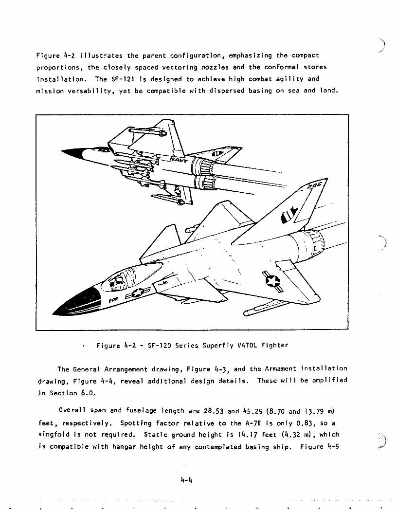
F igu re 4-2 i 1 l u s t r a t e s the parent conf igura t ion , emphasizing the compact
p ropor t ions , t he c l o s e l y spaced vec to r ing nozzles and the conformal s tores
i n s t a l l a t i o n . The SF-121 i s designed t o achieve h i g h combat a g i l i t y and
miss ion v e r s a b i l i t y , y e t be compatible w i t h dispersed basing on sea and land.
I F igu re 4-2 - SF-120 Ser ies Superf ly VATOL F i g h t e r
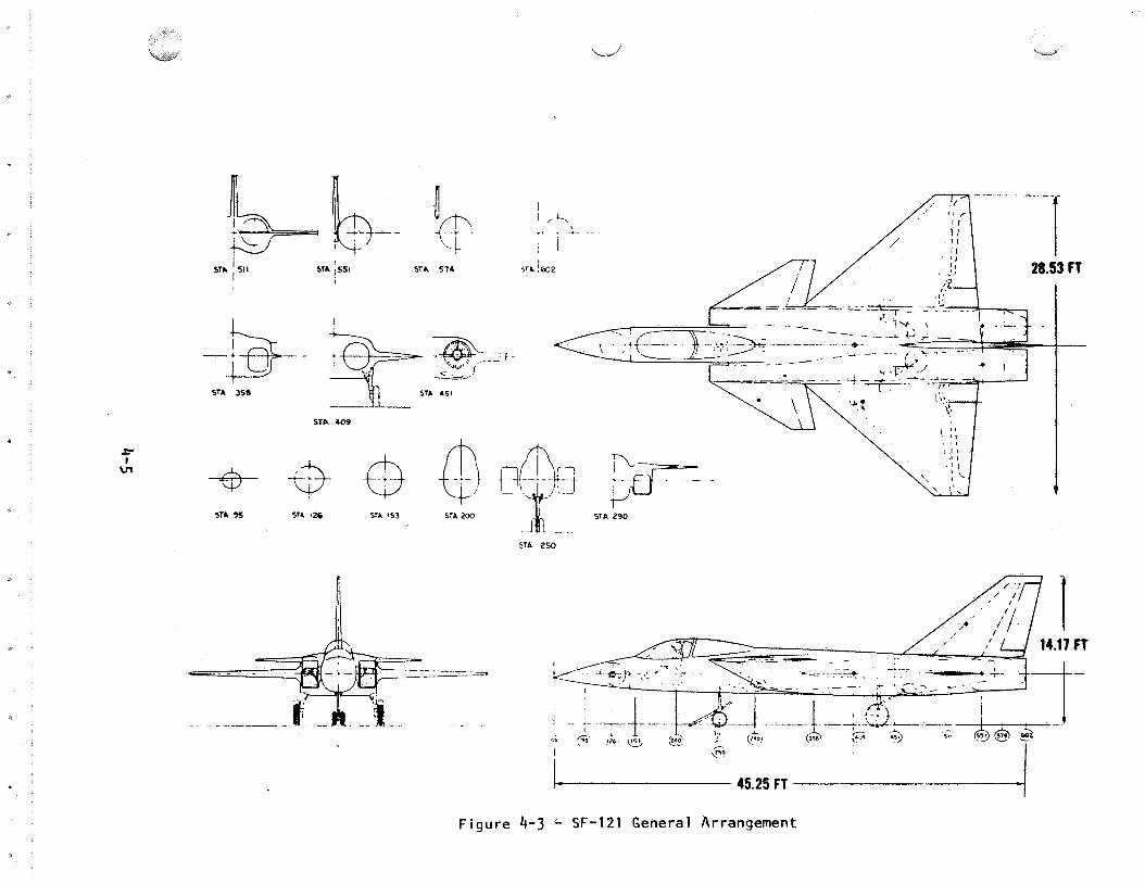
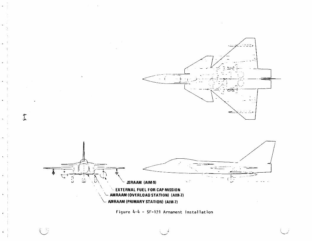
The General Arrangement drawing, F igu re 4-3, and the Armament I n s t a l l a t i o n
drawing, F igure 4-4, reveal a d d i t i o n a l design deta i 1s. These w i 11 be amp1 if ied
i n Sect ion 6.0.
Overa l l span and fuselage length are 28.53 and 45.25 (8.70 and 13.79 m)
fee t , respect ive ly . Spo t t i ng f a c t o r r e l a t i v e t o the A-7E i s on ly 0.83, so a
s i n g f o l d i s no t required. S t a t i c ground he ight i s 14.17 feet (4.32 m), which
i s compatible w i t h hangar he ight o f any contemplated basing ship. F igure 4-5
--....-. -- - - ---- - --_ q . --v -. A - -- - -- . . - L - .- -
-- - _-_-.
- - - " JSRAAM (AIM-9) \ v
. - - -
' '\ '. EXTERNAL FUEL FOR CAP MISSION ' AMRAAM (OVERLOAD STAT1 ON) (Altdl-7)
\- AMRAAM (PRIMARY STATION) (AIM-7)
Figure 4-4 - SF-121 Armament Installation
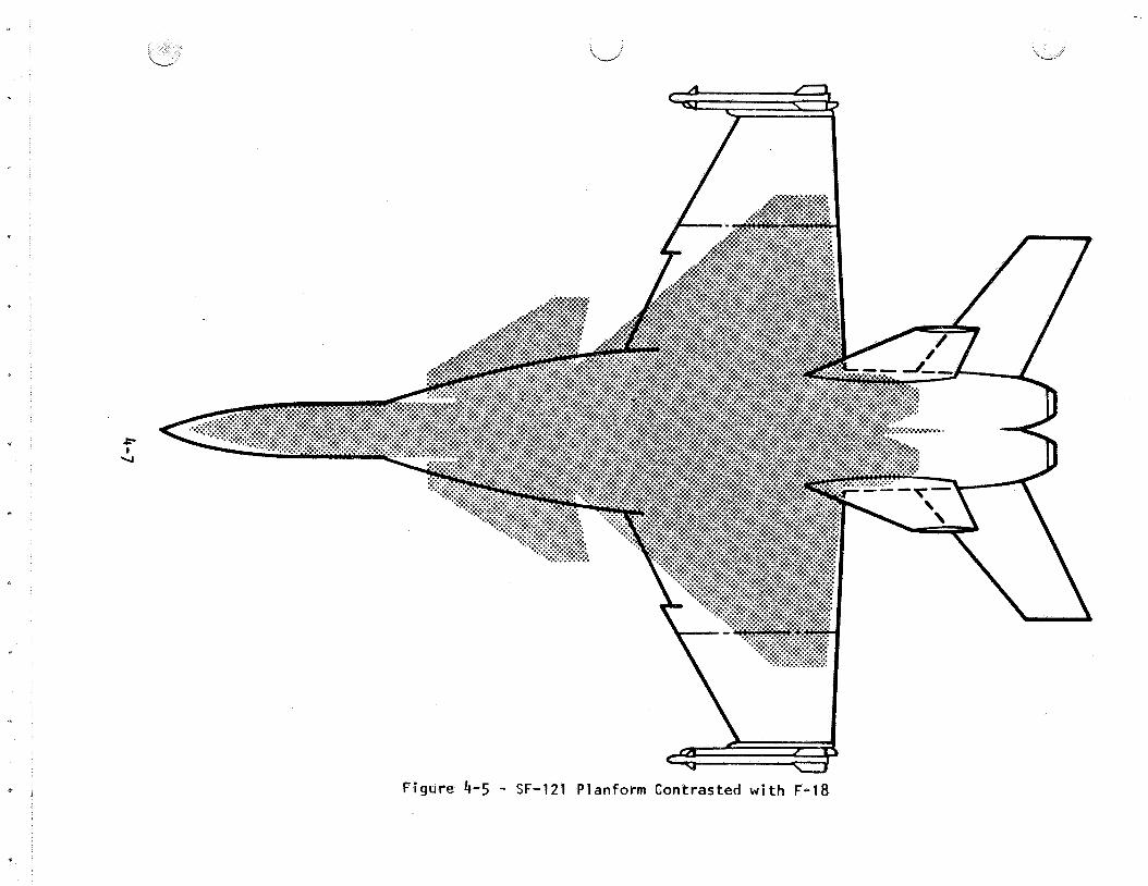
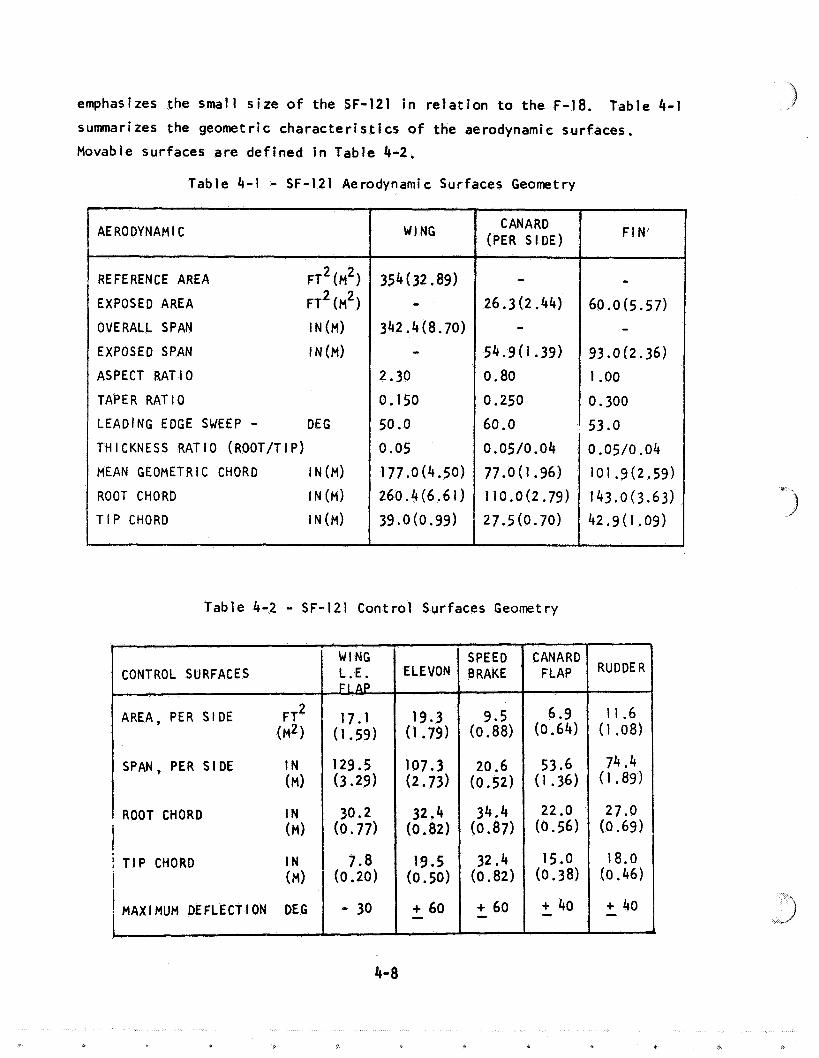
emphasizes the small s i z e o f the SF-121 i n r e l a t i o n t o the F-18. Table 4-1
summarizes the geometric c h a r a c t e r i s t i c s o f the aerodynamic surfaces.
Movable surfaces are de f ined i n Table 4-2.
I AERODYNAMIC
Table 4-1 - SF-121 Aerodynamic Surfaces Geometry
REFERENCE AREA 2 2 FT (M
EXPOSED AREA 2 2 FT ( M )
OVERALL SPAN I N (MI EXPOSED SPAN IN ( M )
ASPECT RATIO
TAPER RATIO
LEADING EDGE SWEEP - DEG
TH l CKNESS RAT I 0 (RoOT/T I P)
MEAN GEOMETR l C CHORD IN (MI
ROOT CHORD IN (MI
TIP CHORD I N (MI
CANARD 'lNG ( (PER s1 DE: ,
Table 4-2 - SF-121 Contro l Surfaces Geometry
L
RUDDER
11.6 (1.08)
74.4 (1.89)
27.0 (0.69)
18.0 (0.46)
- + 40
CANARD FLAP
6.9 (0.64)
53.6 (1.36)
22.0 (0.56)
15.0 (0.38)
- + 40
SPEED BRAKE
9.5 (0.88)
20.6 (0.52)
34.4 (0.87)
32.4 (0.82)
2 60
ELEVON
19.3 (1.79)
107.3 (2.73)
32.4 (0.82)
19.5 (0.50)
- + 60
CONTROL SURFACES
AREA, PER S l DE F T ~ ( ~ 2 )
SPAN, PER S l DE IN
I (M)
I IN (M)
! TIP CHORD IN I (M)
1 M A X I MUM DEFLECT l ON DEG
WING L.E. FI AP
17.1 (1 -59)
129.5 (3.29)
30.2 (0.77)
7.8 (0.20)
- 30
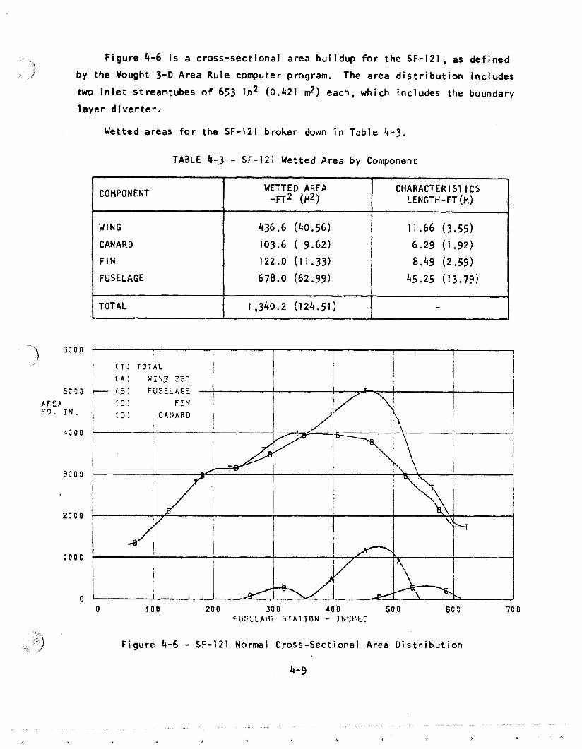
Figure 4-6 i s a cross-sect ional area bu i l dup f o r the SF-121, as def ined
by the Vought 3-D Area Rule computer program. The area d i s t r i b u t i o n inc ludes
two i n l e t streamtubes o f 653 in2 (0.421 I$) each, which includes the boundary
l a y e r d i v e r t e r .
Wetted areas f o r the SF-121 broken down i n Table 4-3.
TABLE 4-3 - SF-121 Wetted Area by Component
I TOTAL
COMPONENT
W I N G
CANARD
FIN
FUSELAGE
5;33 Ar 'C ,A ? 2 . IN.
[ A 1 WIYF 15'
[ B I FUSELAGE
WETTED AREA - F T ~ (M*)
436.6 (40.56)
103.6 ( 9.62)
122.0 (1 1.33)
678.0 (62.99)
F igure 4-6 - SF-121 Normal Cross-Sectional Area D i s t r i b u t i o n
I CHARACTERISTICS
LENGTH-FT (M)
11.66 (3.55)
6.29 (1.92)
8.49 (2.59)
45.25 (13.79)

5.0 AERODYNAMI C CHARACTER1 ST1 CS
The SF-121 was the sub jec t o f d e t a i l e d aerodynamic est imates. Minimum
drag and trimmed drag due t o l i f t were p r e r e q u i s i t e s t o s i z i n g a p o i n t design,
and were determined f i r s t . The f l y i n g q u a l i t i e s parameters were used i n the
t r a n s i t i o n ana lys is . Except f o r minimum drag, wind tunnel data was re1 i e d
upon heavi l y . Vought conducted h i g h speed wind tunnel t es ts ( ~ e f e r e n c e 3) on
a parametr ic f low-through model s i m i l a r t o the SF-121. The model d i f f e r e d i n
several respects which makes i t an imperfect data base, p a r t i c u l a r l y f o r
l a t e r a l -d i r e c t i o n a l c h a r a c t e r i s t i c s . Since the Vought t e s t s extended o n l y t o
a = 35 degrees, a less representa t ive conf igura t ion ( ~ e f e r e n c e 4 ) had t o be
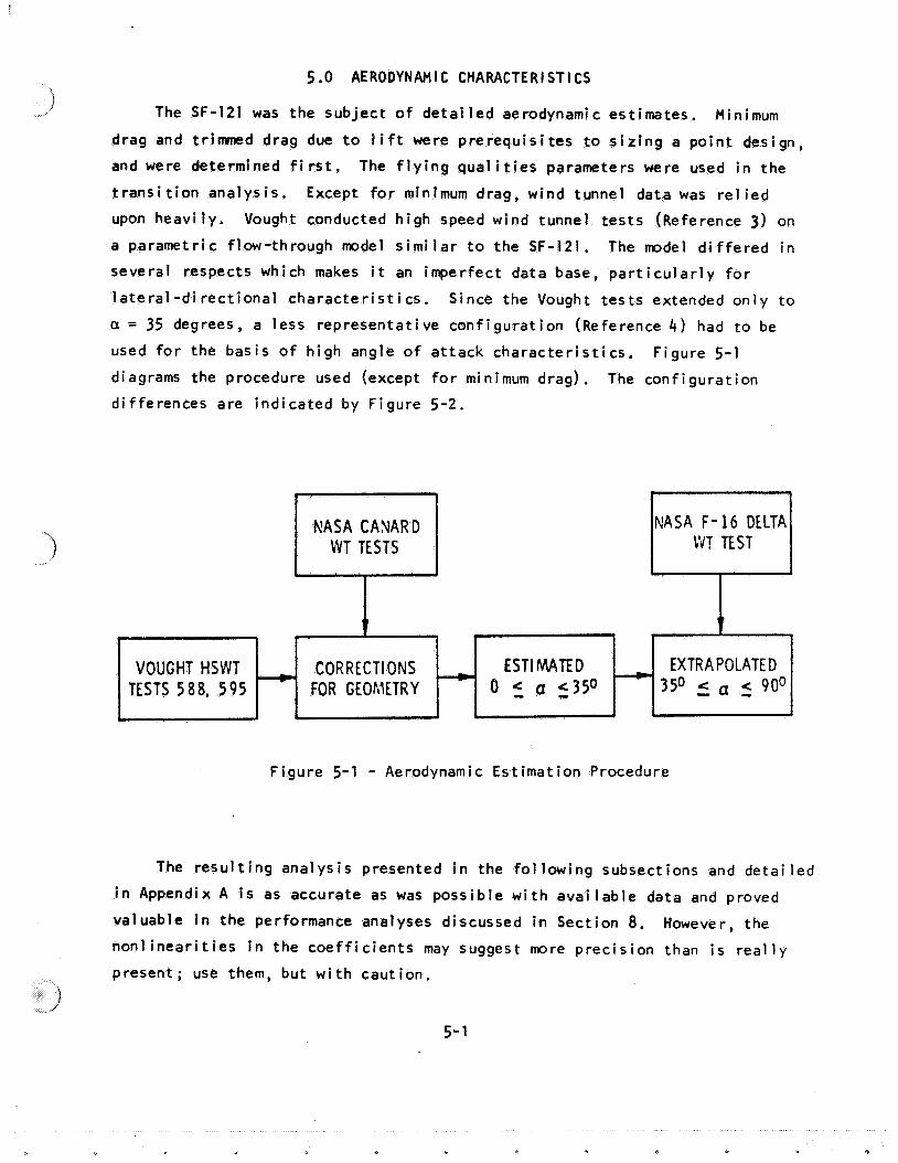
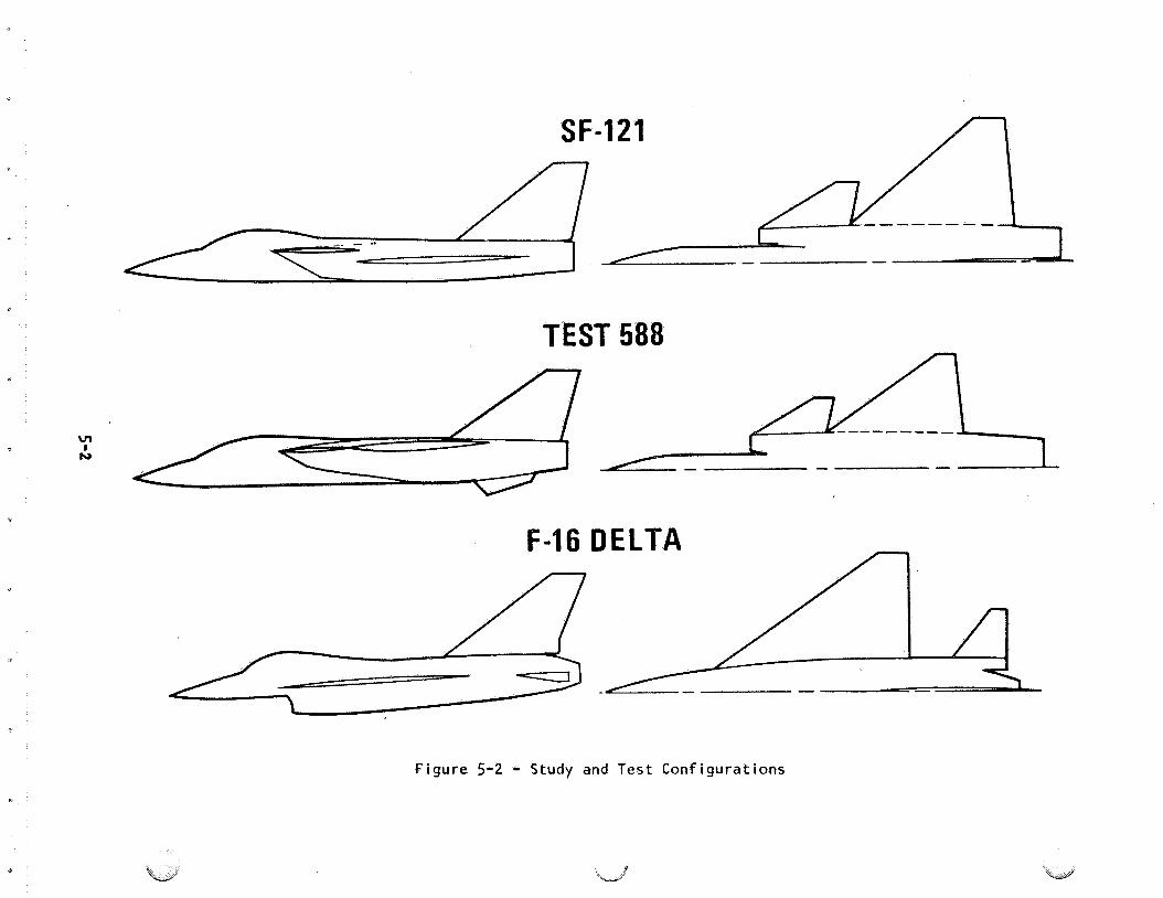
used f o r the bas is o f h i g h angle o f a t t a c k c h a r a c t e r i s t i c s . F igure 5-1
diagrams the procedure used (except f o r minimum drag). The con f igu ra t i on
d i f fe rences are i nd i ca ted by Figure 5-2.
NASA F- 16 DLLTA
Figure 5-1 - Aerodynamic Est imat ion Procedure
The r e s u l t i n g ana lys is presented i n the f o l l o w i n g subsections and d e t a i l e d
i n Appendix A i s as accurate as was poss ib le w i t h a v a i l a b l e data and proved
valuable i n the performance analyses discussed i n Sect ion 8. However, the
nonl i n e a r i t i e s i n the c o e f f i c i e n t s may suggest more p r e c i s i o n than i s real l y
present; use them, but w i t h caut ion .
5.1 LONGITUDINAL CHARACTER1 ST1 CS
5.1.1 Minimum Drag
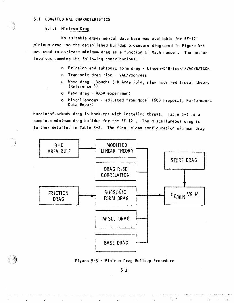
No s u i t a b l e experimental data base was a v a i l a b l e f o r SF-121
minimum drag, so the es tab l ished bu i l dup procedure diagramed i n Figure 5-3 was used t o est imate minimum drag as a func t i on o f Mach number. The method
involves summing the f o l lowing con t r i bu t i ons :
o F r i c t i o n and subsonic form drag - L i nden-OIBrimski/VAC/DATCOM
o Transonic drag r i s e - VAC/Voohrees
o Wave drag - Vought 3-0 Area Rule, p lus modi f ied 1 inear theory ( ~ e f e r e n c e 5 )
o Base drag - NASA experiment
o Miscellaneous - adjusted from Model 1600 Proposal, Performance Data Report
Nozzle/afterbody drag i s bookkept w i t h i n s t a l l e d t h r u s t . Table 5-1 i s a
complete minimum drag bu i ldup f o r the SF-121. The miscel laneous drag i s
f u r t h e r d e t a i l e d i n Table 5-2. The f i n a l c lean con f igu ra t i on minimum drag
MISC. DRAG
*
BASE DRAG J
Figure 5-3 - Hinimum Drag Bui ldup Procedure
5-3
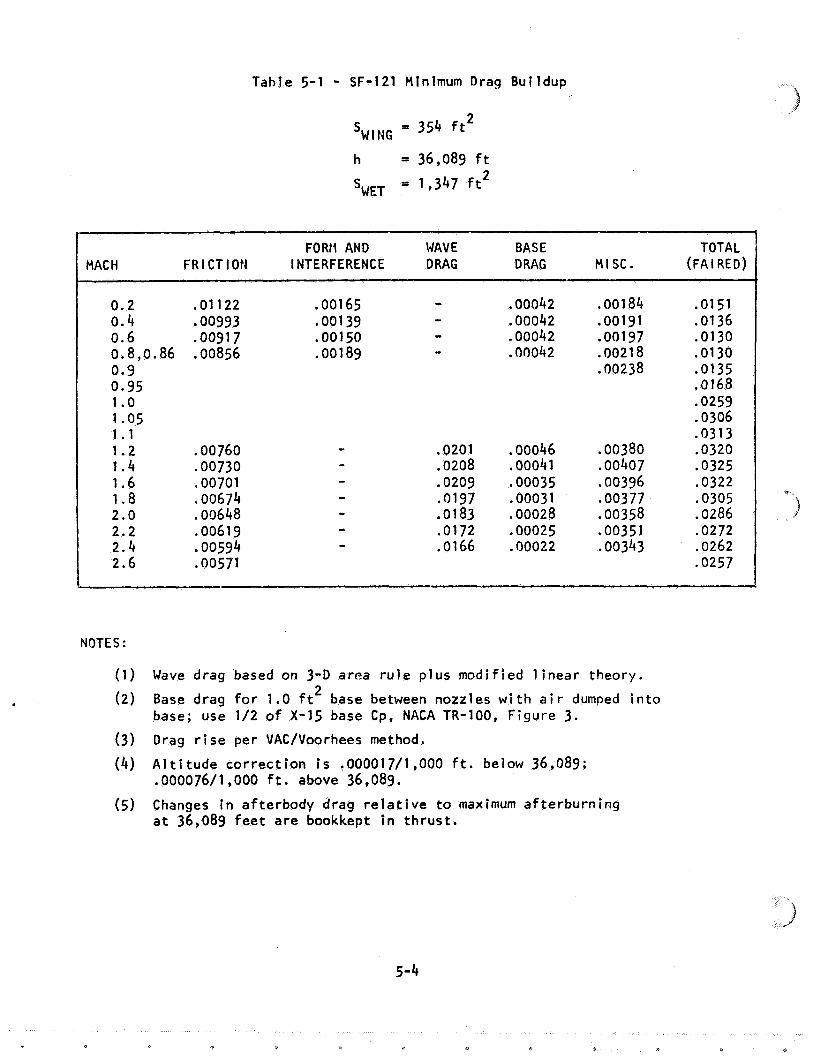
Table 5-1 - SF-121 Mlnlmum Drag Buildup
FORH AND WAVE BASE MACH FRICTIOt4 INTERFERENCE DRAG DRAG M I S C . (FA I RED)
NOTES :
( 1 ) Wave drag based on 3-0 area r u l e p lus modif ied l i n e a r theory.
(2) Base drag f o r 1.0 f t2 base between nozzles w i t h a i r dumped i n t o base; use 1/2 o f X - 1 5 base Cp, NACA TR-100, Figure 3.
(3) Drag r i s e per VAC/Voorhees method.
(4) A l t i t u d e cor rec t ion i s .000017/1,000 ft. below 36,089; .000076/1,000 ft. above 36,089.
(5) Changes i n afterbody drag r e l a t i v e t o maximum af terburn ing a t 36,089 f ee t are bookkept i n thrust .
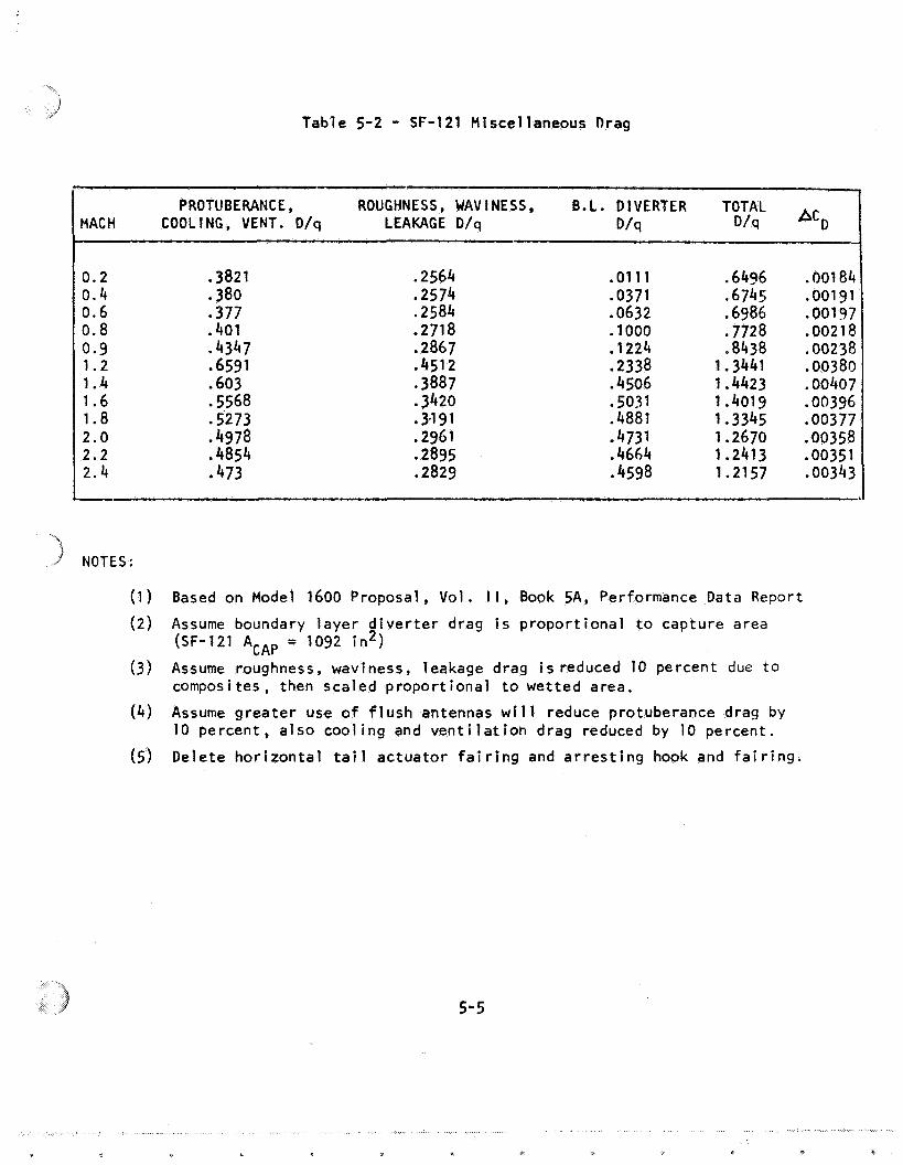
Table 5-2 - SF-121 Miscel laneous Drag
PROTUBERANCE, ROUGHNESS, WAVINESS, B.L. DIVERTER TOTAL MACH COOLING, VENT. D/q LEAKAGE D/q D/q 019 D
0.2 .382 1 ,2564 .0111 ,6496 .00184 0.4 .380 .2574 ,0371 .6745 .001g1 0.6 377 .2584 .0632 .6986 .00197 0.8 .401 .2718 .I000 .7728 .00218 0.9 -4347 ,2867 .I224 .8438 .00238 1.2 -6591 ,4512 .2338 1.3441 .0038o 1.4 .603 .3887 .4506 1 .4423 .00407 1.6 .5568 .3420 .SO31 1 .4019 .On396 1.8 .5273 .3.191 .488 1 1 .3345 .00377 2.0 ,4978 .2961 -4731 1 .2670 ,00358 2.2 .4854 -2895 .4664 1.2413 .00351 2.4 . 473 .2829 .4598 1 .2157 .00343
A
1 NOTES:
(1) Based on Model 1600 Proposal, Vol. I I, Book 5A, Performance Data Report
(2) Assume boundary l aye r d i v e r t e r drag i s p ropor t i ona l t o capture area (SF-121 ACAp = 1092 in2)
(3) Assume roughness, waviness, leakage drag i s reduced 10 percent due t o composi tes , then scaled p ropor t i ona l t o wet ted area.
(4) Assume g rea te r use o f f l u s h antennas w i l l reduce protuberance drag by 10 percent , a l s o coo l i ng and v e n t i l a t i o n drag reduced by 10 percent.
(5) De le te h o r i z o n t a l t a i l ac tua to r f a i r i n g and a r r e s t i n g hook and f a i r i n g .
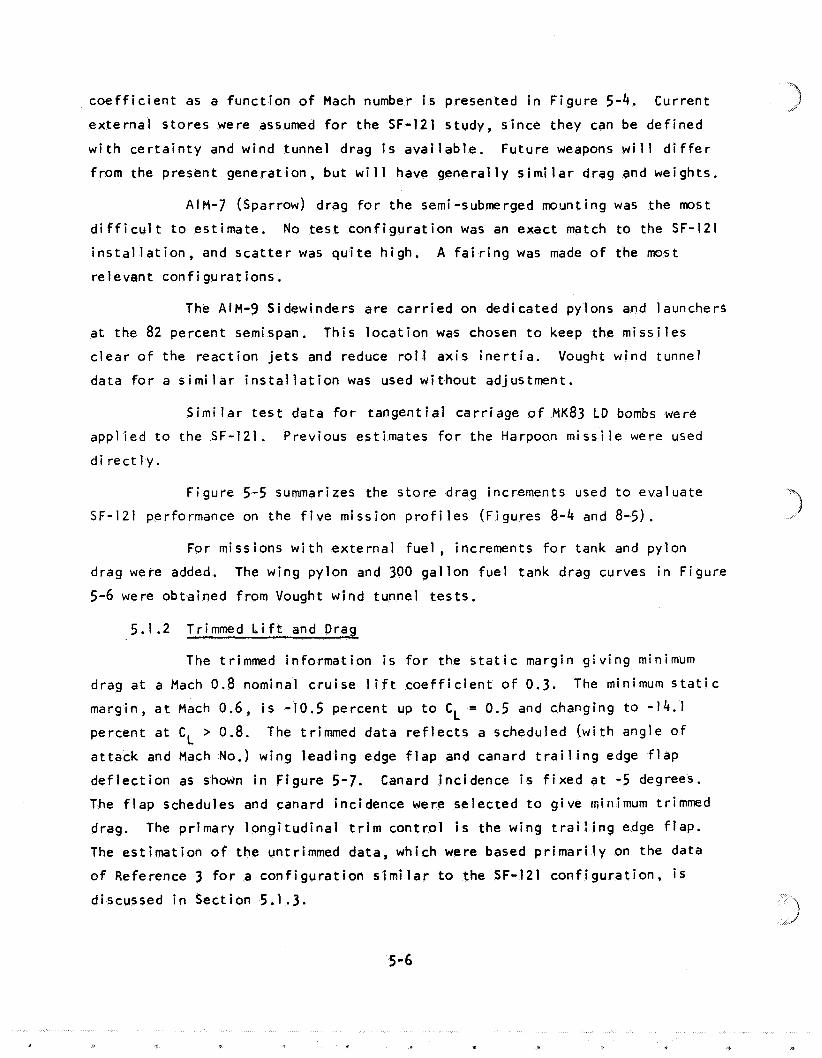
c o e f f i c i e n t as a f u n c t i o n o f Mach number i s presented i n F igure 5-4. Current
ex te rna l s to res were assumed f o r the SF-121 study, s ince they can be def ined
w i t h c e r t a i n t y and wind tunnel drag i s a v a i l a b l e . Future weapons w i l l d i f f e r
from the present generat ion, bu t w i l l have genera l l y s im. i la r drag and weights.
A I M - 7 (Sparrow) drag f o r the semi -submerged mounting was the most
d i f f i c u l t t o est imate. No t e s t c o n f i g u r a t i o n was an exac t match t o the SF-121
i n s t a l l a t i o n , and s c a t t e r was q u i t e h igh . A f a i r i n g was made o f the most
re levant con f i gu ra t i ons .
The AIM-9 Sidewinders are c a r r i e d on dedicated pylons and launchers
a t the 82 percent semispan. Th is l o c a t i o n was chosen t o keep the miss i l e s
c l e a r o f the reac t i on j e t s and reduce to1 l a x i s i n e r t i a . Vought wind tunnel
data f o r a s i m i l a r i n s t a l l a t i o n was used w i thou t adjustment.
S i m i I a r t e s t da ta f o r t angen t ia l ca r r i age o f ~ K 8 3 LD bombs were
appl i e d t o the SF-121. Previous est imates f o r the Harpoon miss i l e were used
d i r e c t l y .
F igure 5-5 summarizes the s t o r e drag increments used t o eva lua te
SF-121 performance on the f i v e miss ion p r o f i l e s (F igures 8-4 and 8-5).
For missions w i t h ex te rna l f u e l , increments f o r tank and py lon
drag were added. The wing py lon and 300 g a l l o n fue l tank drag curves i n F igure
5-6 were obta ined from Vought wind tunnel t e s t s .
5.1.2 Trimmed L i f t and Drag
The trimmed in fo rmat ion i s f o r the s t a t i c margin g i v i n g minimum
drag a t a Mach 0.8 nominal c r u i s e l i f t c o e f f i c i e n t o f 0.3. The minimum s t a t i c
margin, a t Mach 0.6, i s -10.5 percent up t o CL = 0.5 and changing t o -14.1
percent a t CL > 0.8. The trimmed data r e f l e c t s a scheduled ( w i t h angle o f
a t t a c k and Mach No.) wing lead ing edge f l a p and canard t r a i 1 i n g edge f l a p
d e f l e c t i o n as shown i n F igure 5-7. Canard inc idence i s f i x e d a t -5 degrees.
The f l a p schedules and canard inc idence were se lec ted t o g i v e rfiir~irnum trimmed
drag. The pr imary l o n g i t u d i n a l t r i m c o n t r o l i s the wing t r a i : i n g edge f lap .
The es t ima t ion o f the untrimmed data, which were based p r i m a r i l y on the data
o f Reference 3 f o r a c o n f i g u r a t i o n s i m i l a r t o the SF-121 c o n f i g u r a t i o n , i s
discussed i n Sect ion 5.1.3.
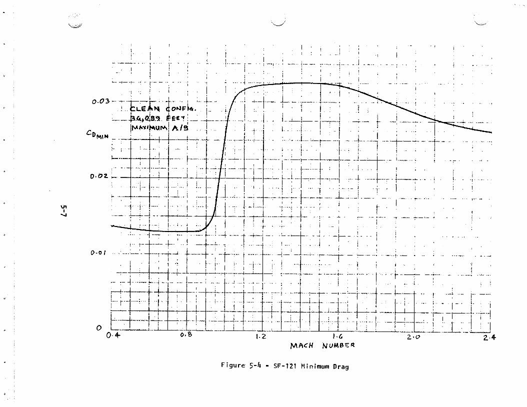
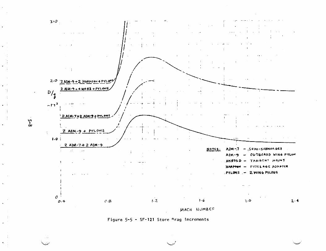
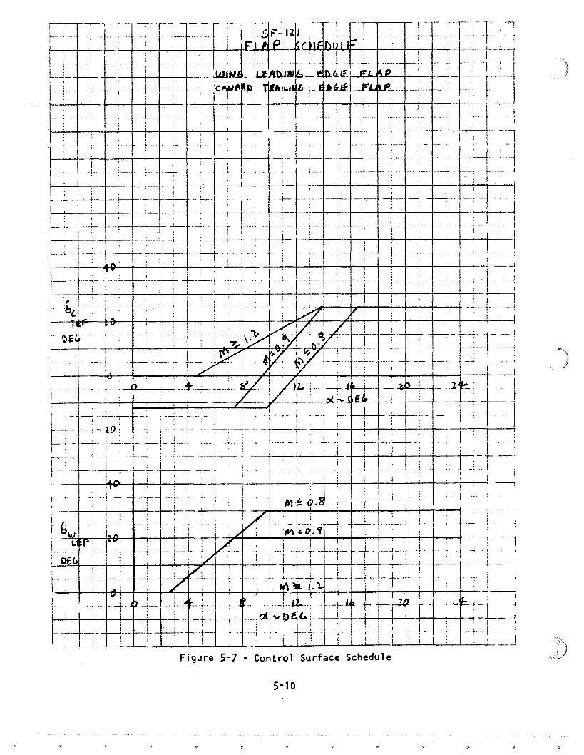
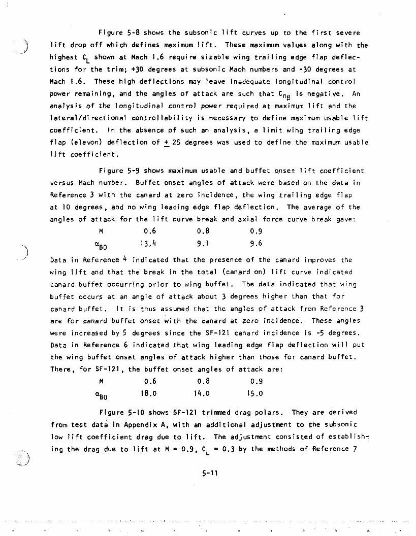
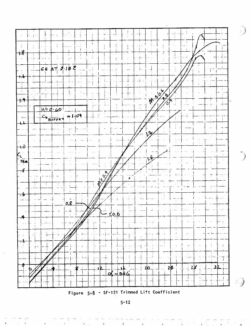
Figure 5-8 shows the subsonic l i f t curves up t o the f i r s t severe
l i f t drop o f f which def ines maximum l i f t . These maximum values a long w i t h the
h ighest CL shown a t Mach 1.6 requi re s i z a b l e wing t r a i 1 i ng edge f l a p de f lec -
t i o n s f o r t he t r i m ; +30 degrees a t subsonic Mach numbers and -30 degrees a t
Mach 1.6. These h i g h de f lec t i ons may leave inadequate l o n g i t u d i n a l con t ro l
power remaining, and the angles o f a t t a c k are such t h a t C i s negat ive. An B ana lys i s o f the l o n g i t u d i n a l con t ro l power requ i red a t maximum l i f t and the
l a t e r a l / d i rec t i ona l con t ro l l a b i 1 i t y i s necessary t o def ine maximum usable 1 i f t
c o e f f i c i e n t . I n the absence o f such an ana lys is , a 1 i m i t wing t r a i l i n g edge
f l a p (elevon) d e f l e c t i o n o f - + 25 degrees was used t o def ine the maximum usable
l i f t c o e f f i c i e n t .
F igure 5-9 shows maximum usable and b u f f e t onset 1 i f t c o e f f i c i e n t
versus Mach number. B u f f e t onset angles o f a t tack were based on the data i n
Reference 3 w i t h the canard a t zero incidence, the wing t r a i l i n g edge f l a p
a t 10 degrees, and no wing leading edge f l a p d e f l e c t i o n . The average o f the
angles o f a t tack f o r t he 1 i f t curve break and a x i a l fo rce curve break gave:
M 0.6 0.8 0.9
a t 3 ~ 13.4 9.1 9.6
Data i n Reference 4 ind ica ted t h a t the presence o f the canard improves the
wing 1 i f t and t h a t the break i n the t o t a l (canard on) 1 i f e curve i nd i ca ted
canard b u f f e t occu r r i ng p r i o r t o wing b u f f e t . The data i nd i ca ted t h a t w ing
b u f f e t occurs a t an angle o f a t tack about 3 degrees h igher than t h a t f o r
canard b u f f e t . I t i s thus assumed t h a t the angles o f a t t a c k from Reference 3 are f o r canard b u f f e t onset w i t h the canard a t zero incidence. These angles
were increased by 5 degrees s ince the SF-121 canard incidence i s -5 degrees.
Data i n Reference 6 i nd i ca ted t h a t wing lead ing edge f l a p d e f l e c t i o n w i 11 put
the wing b u f f e t onset angles o f a t tack h igher than those f o r canard b u f f e t .
There, f o r SF-121, the b u f f e t onset angles o f a t tack are:
M 0.6 0.8 0.9
a ~ o 18.0 14 .O 15.0
Figure 5-10 shows SF-121 t r imned drag po lars . They are der ived
f rom t e s t data i n Appendix A, w i t h an a d d i t i o n a l adjustment t o the subsonic
low l i f t c o e f f i c i e n t drag due t o l i f t . The adjustment cons is ted o f e s t a b l i s h -
i n g the drag due t o l i f t a t H = 0.9, tL = 0.3 by the methods o f Reference 7
? ..*'
Figure 5-8 - SF-121 Trimmed Lift Coefficient
5-12
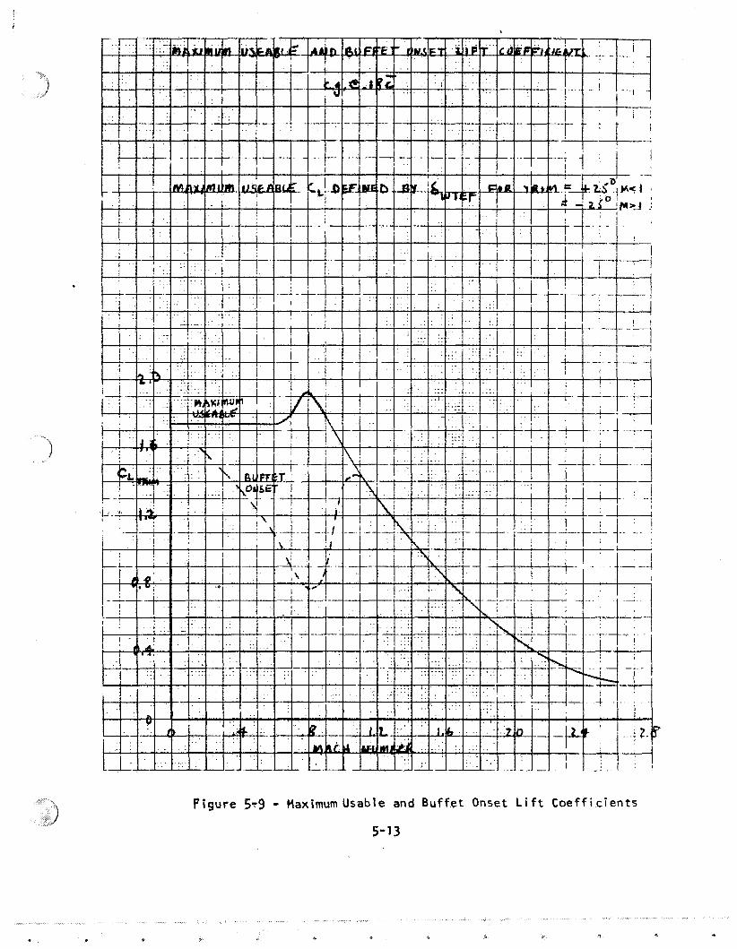
Figure 579 - HaximumUsable and B u f f e t Onset L i f t Coefficients
5-13
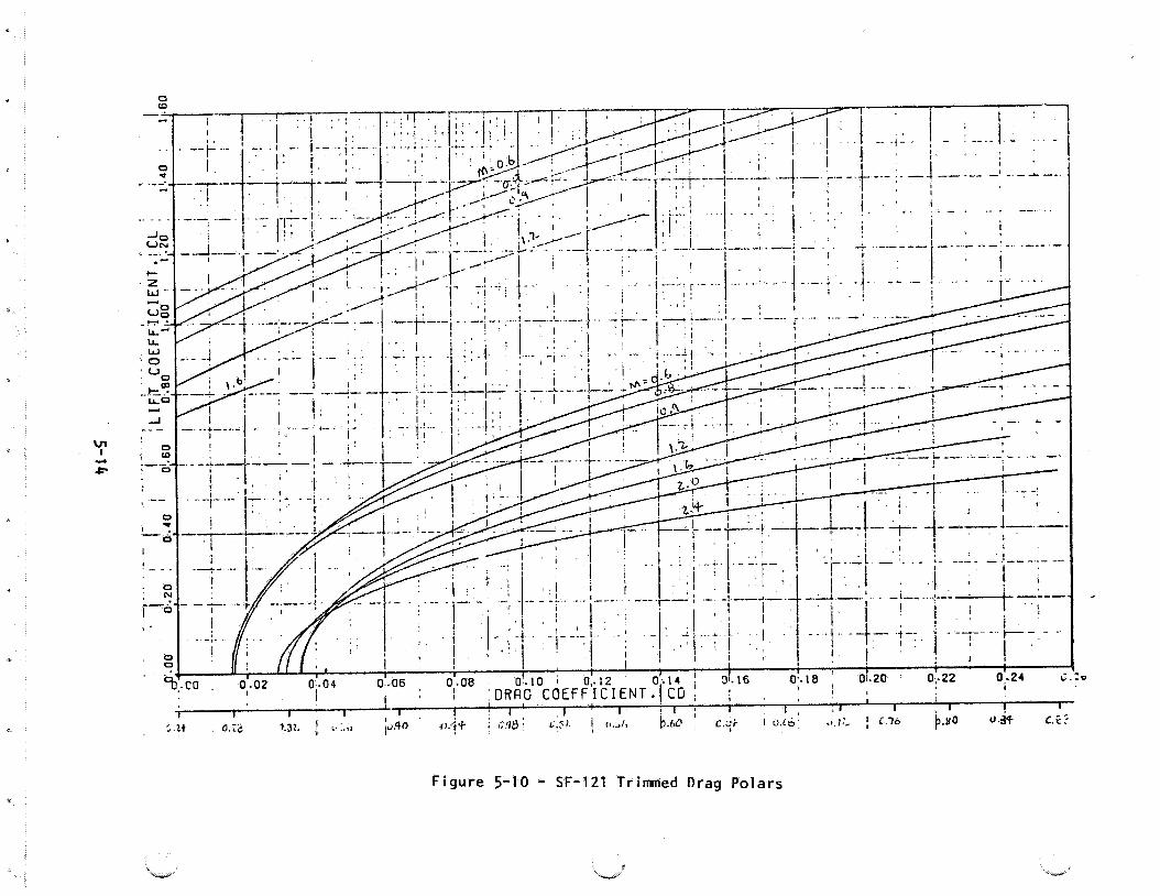
Figure 5-10 - SF-121 Trimmed Drag Polars
and fairing from there to the trimmed levels of the data in Appendix A at
lift coefficients of 0.5 at M = 0.6, 0.8 at H = 0.8, and 0.65 at M = 0.9.
The data of Reference 7 are based on flight tests, and thus reflect levels
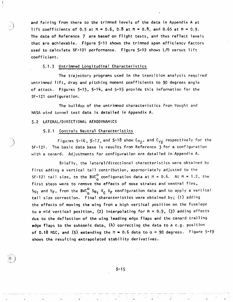
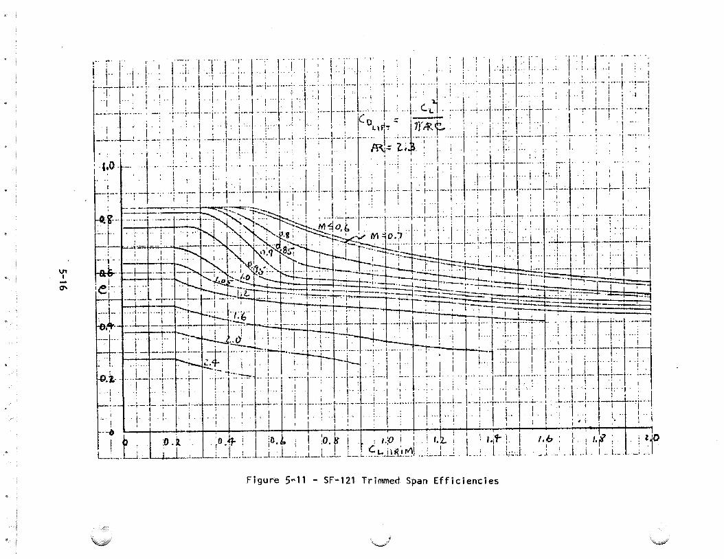
that are achievable. Figure 5-11 shows the trimmed span efficiency factors used to calculate SF-121 performance. Figure 5-12 shows L/D versus lift
coefficient.
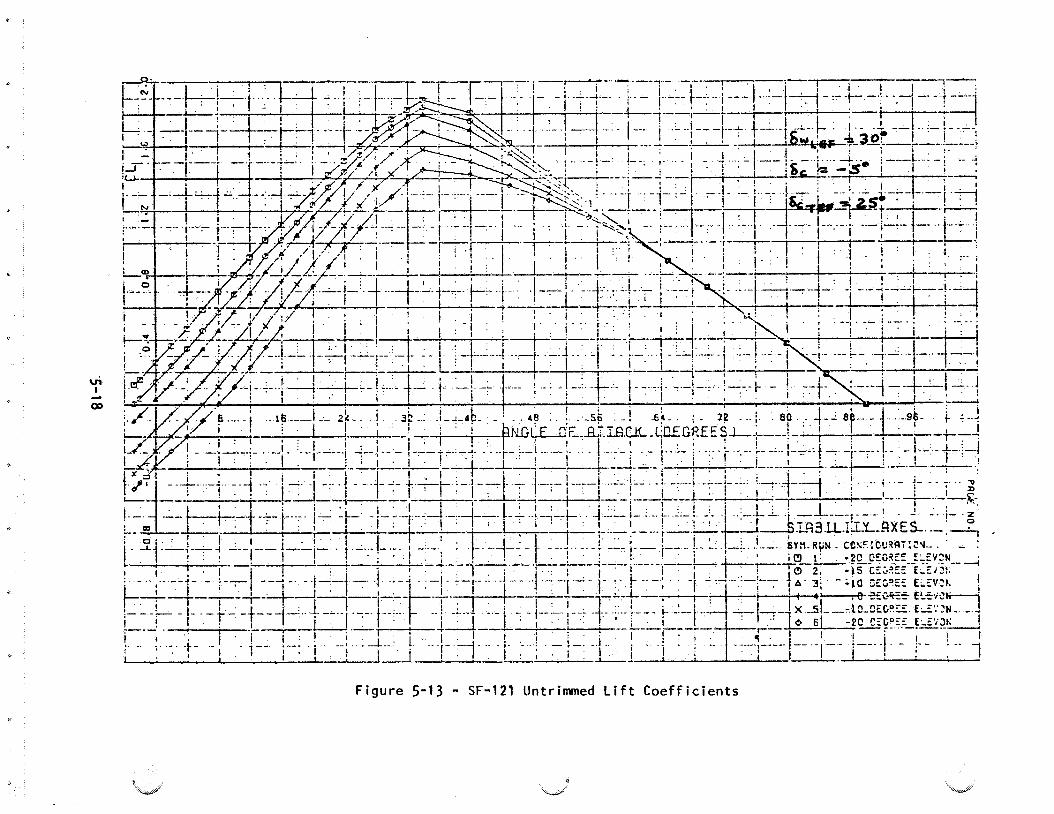
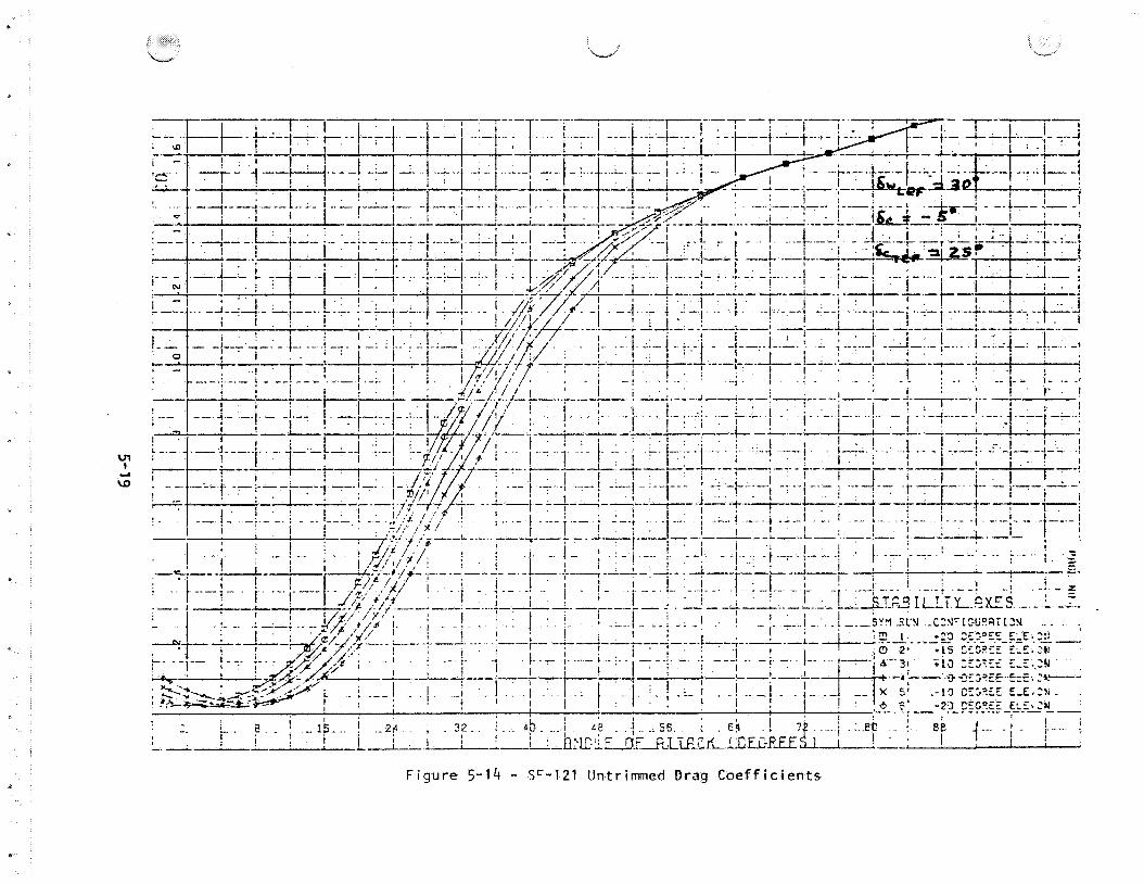
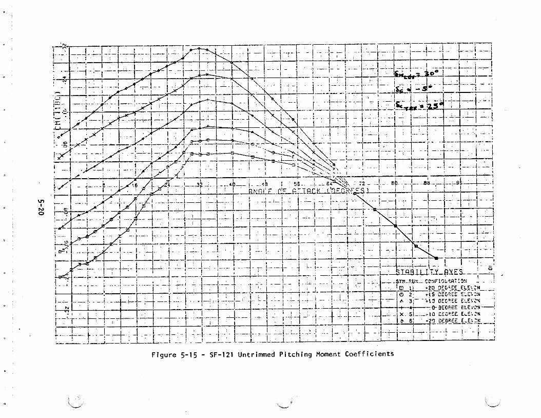
5.1.3 Untrimmed Lonaitudinal Characteristics
The trajectory programs used in the transition analysis required
untrimmed lift, drag and pitching moment coefficients to 90 degrees angle
of attack. Figures 5-13, 5-14, and 5-15 provide this information for the
SF-121 configuration.
The buildup of the untrimmed characteristics from Vought and
NASA wind tunnel test data is detailed in Appendix A.
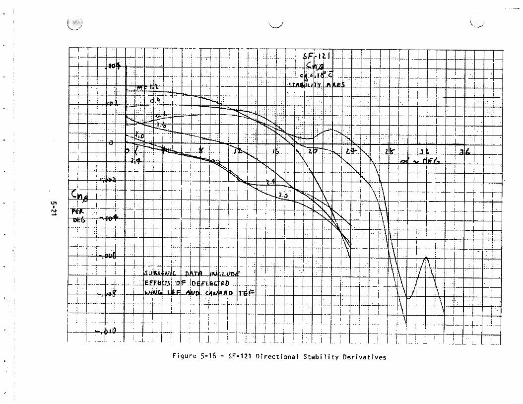
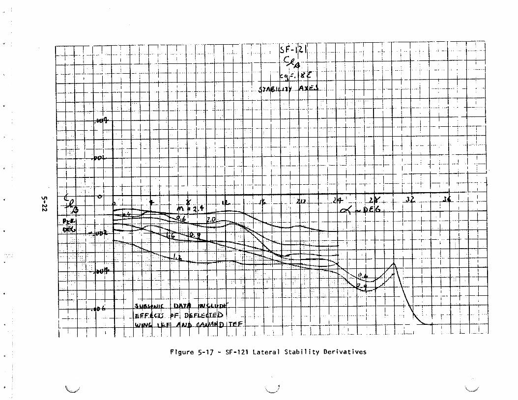
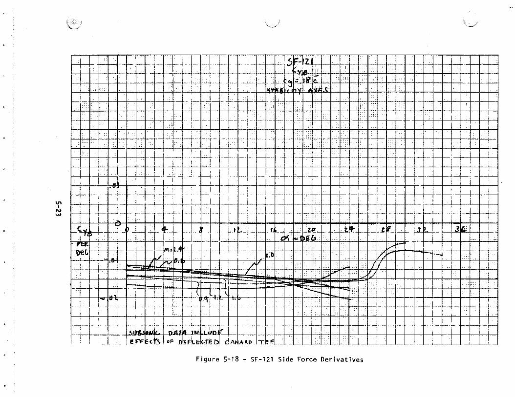
5.2 LATERAL/DIRECTlONAL AERODYNAMICS
5.2.1 Controls Neutral Characteristics
Figures 5-16, 5-17,and 5-18 showCng, a n d C respectively for the y 6
SF-121. The basic data base is results from Reference 3 for a configuration
with a canard. Adjustments for configuration are detailed in Appendix A.
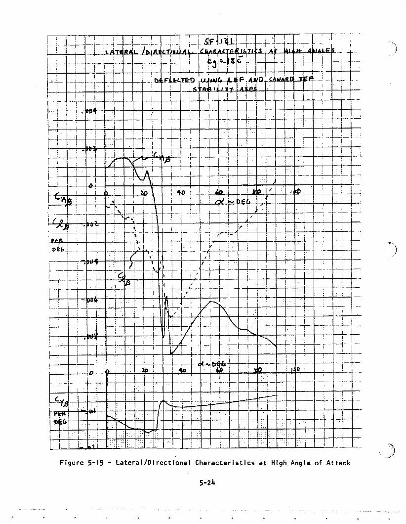
Briefly, the lateral/directional characteristics were obtained by
first adding a vertical tail contribution, appropriately adjusted to the
SF-121 tail size, to the B\JCO configuration data at I! = 0.6. At tl = 1.2, the 0
first steps were to remove the effects of nose strakes and ventral fins,
Sul and VF, from the BWC; S N ~ VC VF configuration data and to apply a vertical
tail size correction. Final characteristics were obtained by; (1) adding
the effects of moving the wing from a high vertical position on the fuselage
to a mid vertical position, (2) interpolating for M = 0.9, (3) adding effects
due to the deflection of the wing leading edge flaps and the canard trailing
edge flaps to the subsonic data, (4) correcting the data to a c.g. position
of 0.18 MGC, and (5 ) extending the It 0.6 data to a = 90 degrees. Figure 5-19
shows the resulting extrapolated stability derivatives.
-. - - . . -
Figure 5-19 - Lateral/Directional Characterlstlcs at Hlgh Angle of Attack
5.2.2 Control Surface Effectiveness
Figures 5-20 and 5-21 show SF-121 a i l e r o n and rudder con t ro l
ef fect iveness. The charac te r i s t i cs are based on the t es t data from Referen-
ces 3 and 6. The methods o f Reference 7 were used t o ob ta in cor rect ions f o r
t e s t model and SF-121 geometry dif ferences and fo r llach number e f fec ts were
necessary. Extension o f the N = 0.6 data t o a = 90 degrees ( f o r t r a n s i t i o n
analysis) was made using the trends i n Reference 8 f o r the de l t a wing conf i g -
ura t ion, w i t h the resu l t s presented i n Figure 5-22. The cor rect ions f o r h igh
con t ro l surface def lec t ions (Figure 5-23) are from Reference 9.
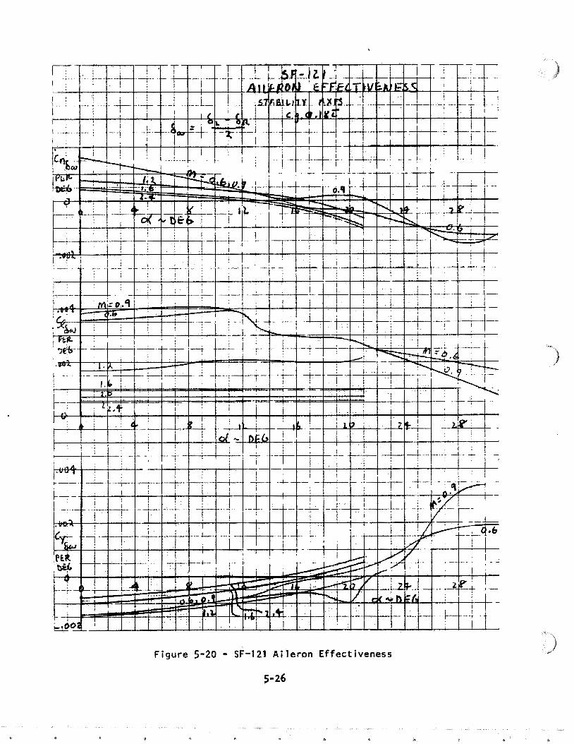
Figure 5-20 - SF-121 Aileron Effectiveness
5-26
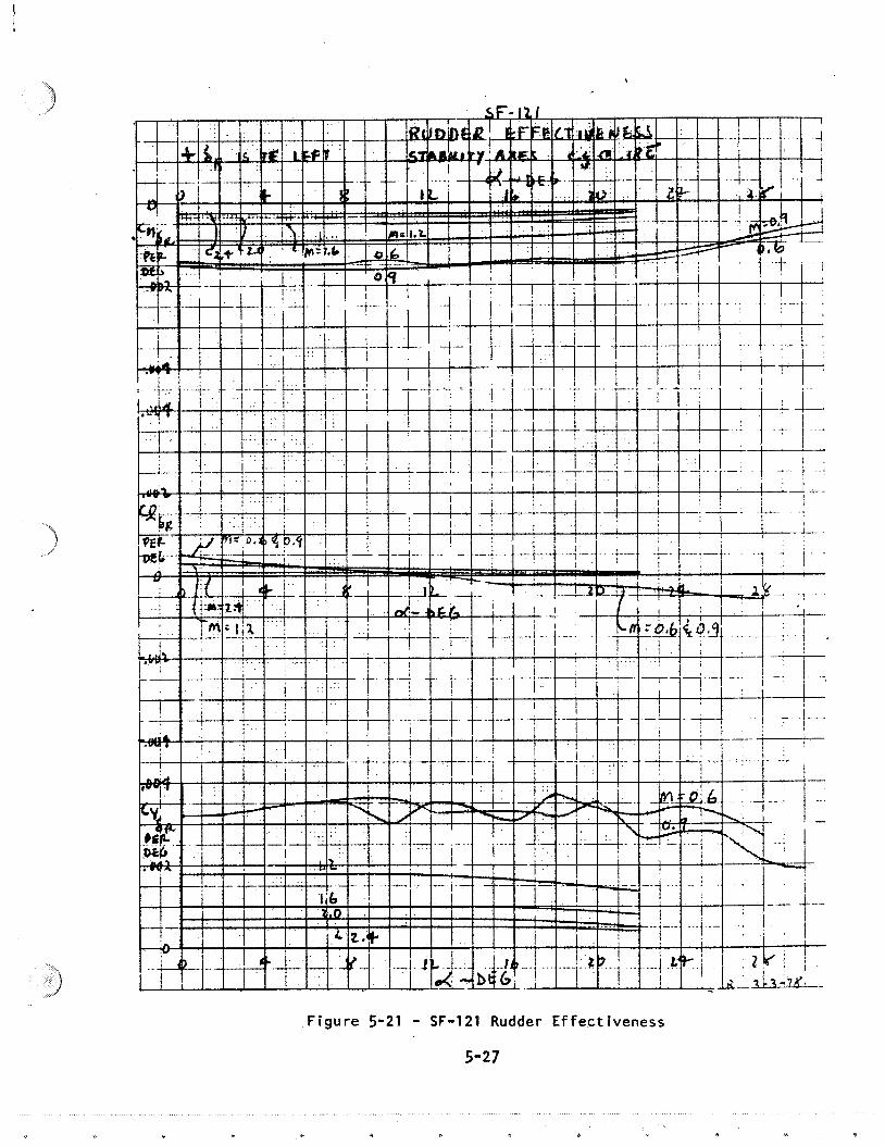
Figure 5-21 - SF-121 Rudder Ef fect iveness
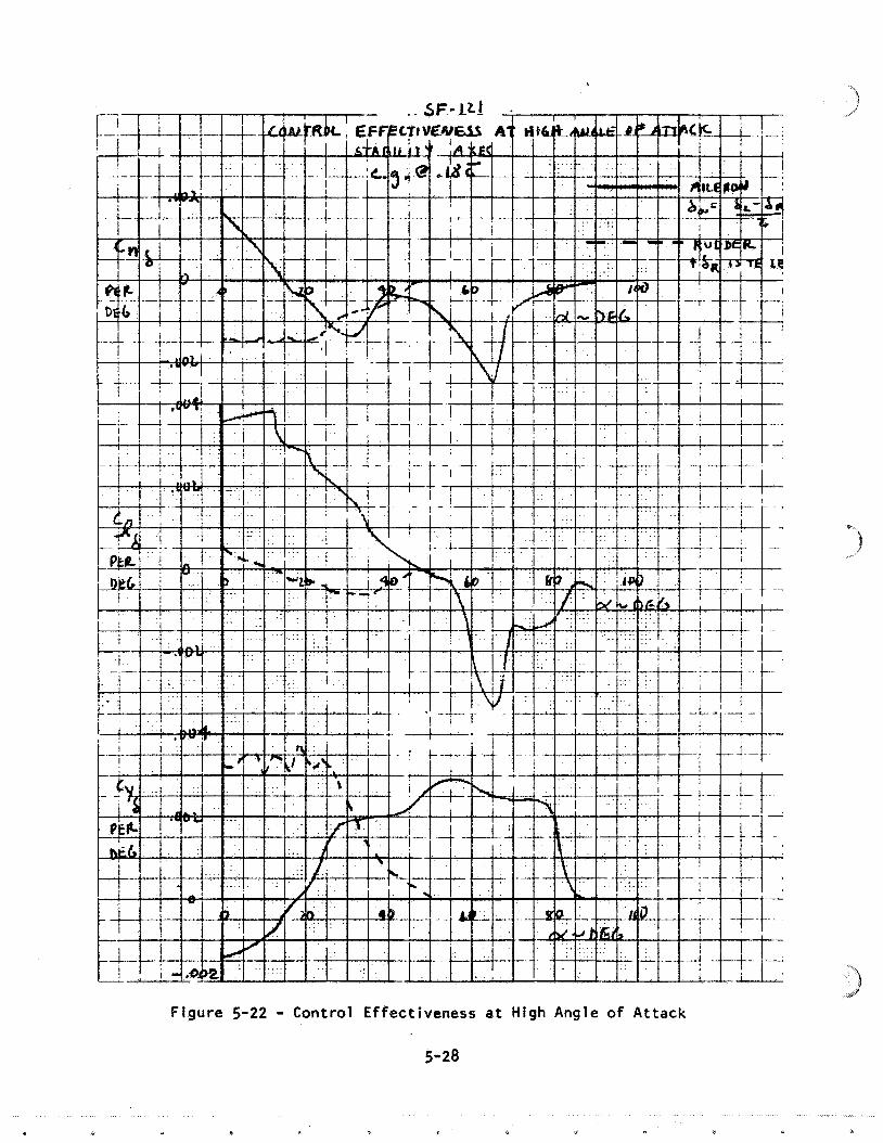
Figure 5-22 - Control Effectiveness at High Angle of Attack
5-28
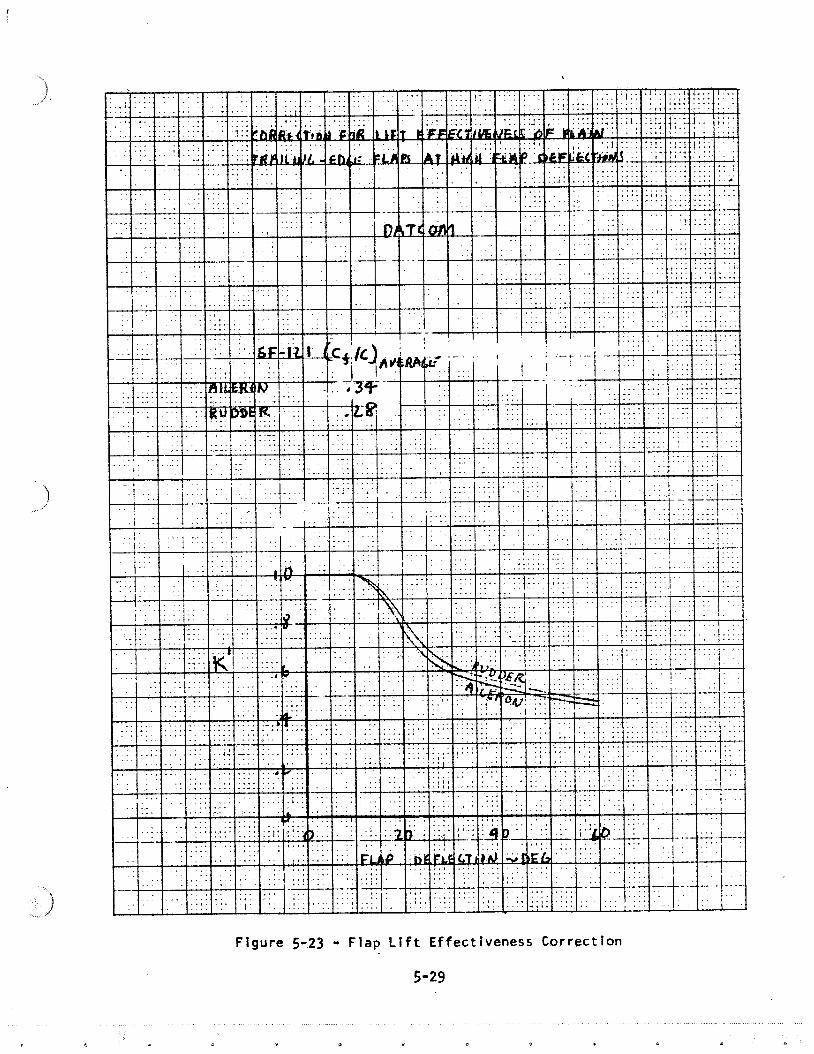
Flgure 5-23 - Flap Lift Effectiveness Correction

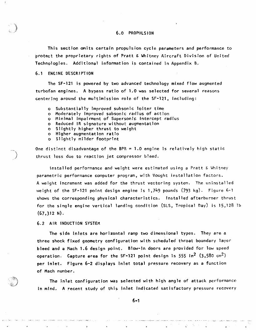
This s e c t i o n omi ts c e r t a i n propu ls ion cyc le parameters and performance t o
p r o t e c t the p r o p r i e t a r y r i g h t s o f P r a t t & Whitney A i r c r a f t D i v i s i o n o f Un i ted
Technologies. Add i t i ona l in format ion i s contained i n Appendix B.
6.1 ENGINE DESCRIPTION
The SF-121 i s powered by two advanced technology mixed f l o w augmented
tu rbofan engines. A bypass r a t i o o f 1.0 was selected f o r several reasons
center ing around the mu l t im iss ion r o l e o f the SF-121, inc lud ing:
o S u b s t a n t i a l l y improved subsonic l o i t e r t ime o Moderately improved subsonic rad ius o f a c t i o n o Minimal impairment o f Supersonic In te rcep t radius o Reduced I R s ignature w i thout augmentation o S l i g h t l y h igher t h r u s t t o weight o Higher augmentation r a t i o o S l i g h t l y m i l d e r f o o t p r i n t
One d i s t i n c t disadvantage o f t he BPR = 1.0 engine i s r e l a t i v e l y h i g h s t a t i c
t h r u s t loss due t o reac t i on j e t compressor bleed.
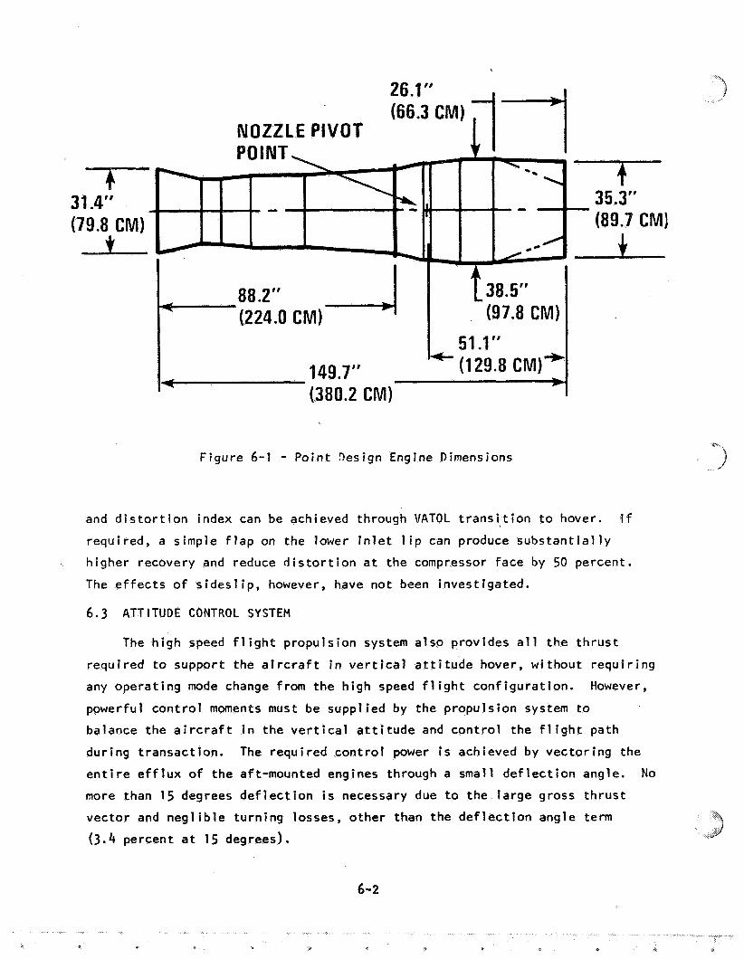
I n s t a l l e d performance and weight were est imated us ing a P r a t t & Whitney
parametr ic performance computer program, w i t h Vought i n s t a l l a t i o n fac tors .
A weight increment was added f o r the t h r u s t vec to r ing system. The u n i n s t a l l e d
weight o f the SF-121 p o i n t design engine i s 1,749 pounds (793 kg ) . F igure 6-1
shows t h e corresponding phys ica l c h a r a c t e r i s t i c s . l n s t a l l e d a f te rbu rne r t h r u s t
f o r the s i n g l e engine v e r t i c a l landing cond i t i on (SLS, T rop ica l nay) i s 15,128 l b
(67,312 N).
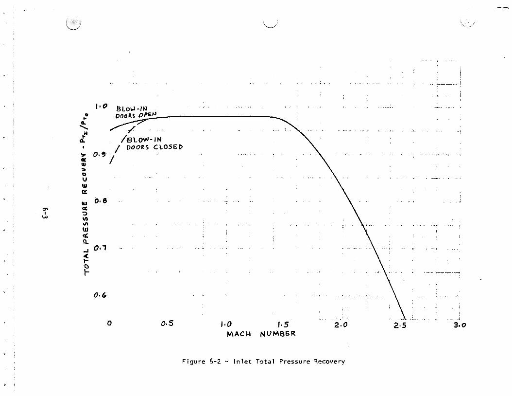
6.2 AIR INDUCTION SYSTEM
The s i d e i n l e t s a r e h o r i z o n t a l ramp two dimensional types. They a r e a
th ree shock f i x e d geometry c o n f i g u r a t i o n w i t h scheduled t h r o a t boundary layer
b leed and a Hach 1.6 design p o i n t . Blow-in doors a r e provided f o r low speed
operat ion. Capture area f o r t he SF-121 p o i n t design i s 555 i n2 (3,580 cm2)
per i n l e t . F igu re 6-2 d i sp lays i n l e t t o t a l pressure recovery as a f u n c t i o n
o f Mach number.
The i n l e t c o n f i g u r a t i o n was se lec ted w i t h h i g h angle o f a t t a c k performance
i n mind. A recent study o f t h i s i n l e t i nd i ca ted s a t i s f a c t o r y pressure recovery
NOZZLE PIVOT
Figure 6-1 - Point nesign Engine Dimensions
and d i s t o r t i o n index can be achieved through VATOL t r a n s i t i o n t o hover. I f
required, a simple f l a p on the lower i n l e t l i p can produce subs tan t ia l l y
higher recovery and reduce d i s t o r t i o n a t the compressor face by 50 percent.
The e f f ec t s o f s ides l ip , however, have not been investigated.
6.3 ATTITUDE CONTROL SYSTEM
The h igh speed f l i g h t propuls ion system a lso provides a l l the t h rus t
required t o support the a i r c r a f t i n v e r t i c a l a t t i t u d e hover, wi thout requ i r ing
any operat ing mode change from the h igh speed f l i g h t conf igurat ton. However,
powerful con t ro l moments must be suppl ied by the propuls ion system t o
balance the a i r c r a f t i n the v e r t i c a l a t t i t u d e and con t ro l the f l i g h t path
dur ing t ransact lon. The required con t ro l power i s achieved by vector ing the
e n t i r e e f f l u x o f the aft-mounted engines through a small de f l ec t i on angle. No
more than 15 degrees de f l ec t i on i s necessary due t o the large gross th rus t
vector and neg l i b l e turn ing losses, other than the de f l ec t i on angle term
(3.4 percent a t 15 degrees).
)I
Thrust vec to r ing i n p i t c h and yaw axes i s achieved by a gimbal mechanism
between the nozzle assembly and the a f te rbu rne r casing. The gas f l o w path
i s e s s e n t i a l l y unchanged, and the gimbal mechanism need not increase the t o t a l
length o f the engine. Indeed, the gas seals w i l l rece ive s l i g h t l y lower heat
i npu t by main ta in ing constant length. However, the p i v o t p o i n t should be as
c lose t o the nozzle e x i t p lane i n order t o maximize e f f e c t i v e moment arm and
minimize movable mass and phys ica l t r a v e l .
The axisymmetr ic g imbal led (GAX) nozzle was se lec ted f o r the SF-121
over j e t vanes and two-dimensional nozzles. De ta i l ed s tud ies o f vec to r ing
nozzles (Reference 10) i n d i c a t e t h a t the g imbal led axisymmetric basel inewas
l i g h t e r than 2-D co~lcepts and had genera l ly b e t t e r t h r u s t performance
(dependent on c o n f i g u r a t i o n i n t e g r a t i o n and f l i g h t cond i t i ons ) . Development
cos t i s l i k e l y t o be lower f o r the G k X , expec ia l l y i f an e x i s t i n g engine/
nozzle i s adapted.
A ser ious l i m i t a t i o n o f 2-0 vec to r ing nozzles f o r 'IATOL a p p l i c a t i o n i s
the a b i l i t y t o vec tor i n p i t c h on ly . Adding a l a t e r a l a x i s would e n t a i l
a d d i t i o n a l complexity and weight. Hybr id systems, such as a 2-D p i t c h nozzle
and yaw bleed j e t s o r j e t vanes a re poss ib le a l t e r n a t i v e s , bu t may no t provide
s u f f i c i e n t c o n t r o l power t o cope w i t h an engine f a i l u r e i n a tw in engine
con f igu ra t i on . I n add i t i on , systems which requ i re h i g h compressor b leed a i r -
f l ow r e s t r i c t the choice o f p ropu ls ion bypass r a t i o .
J e t vanes a re less e f f i c i e n t than vec to r ing nozzles and pose several
design and opera t ing problems when app l i ed t o an a f te rbu rn ing engine:
o Exposure t o a f te rbu rne r temperatures o Thrust l oss (drag) a t zero vec tor angle o Nozzle area v a r i a t i o n s changing area i n j e t o r
compl icat ing mounting p rov i s ions o Probable he igh t I R and radar s ignature.
For these reasons the GAX approach was selected f o r the SF-121. The two a x i s
gimbal system provides compensation f o r an engine f a i l u r e by a l a t e r a l
d e f l e c t i o n which d i r e c t s the remaining t h r u s t vec tor through the a i r p l a n e
center o f mass. The c lose spacing o f the Superf ly engines holds the requ i red
d e f l e c t i o n t o less than e i g h t degrees. The gimbals a r e i n s t a l l e d w i t h an
e i g h t degree outward b ias so f u l l - + 15 degree yaw c o n t r o l i s s t i l l a v a i l a b l e
i n an engine o u t s i t u a t i o n . For normal t w i n engine opera t i on t h e nozzles are
de f lec ted inward t o cancel the b ias and minimize base drag.
6-4
The tw in engine arrangement can generate a l l required r o l l cont ro l power
i n t r a n s i t i o n and hover by d i f f e r e n t i a l nozzle def lec t ions. This ac t ion e n t a i l s
minimal t h rus t loss and i s eas i l y harmonized w i t h p i t c h and yaw commands.
Unfortunately, the loss o f one engine means a loss o f r o l l cont ro l . The
SF-121 uses a react ion j e t system f o r r o l l cont ro l . Each engine suppl ies
h igh pressure compressor bleed a i r t o react ion j e t s a t the wingt ips. The
react ion system i s adequate f o r a l l f l i g h t condi t ions yet examined, but does
cause a s i g n i f i c a n t t h rus t loss which i s re f lec ted i n engine s ize. For two
engines VATOL operat ion thk SF-121 phases d i f f e r e n t i a l nozzle de f lec t ion and
reac t ion j e t s f o r optimum response and f l y i n g q u a l i t i e s . This ex t ra cont ro l
power i s used t o advantage during v e r t i c a l takeof f a t maximum weight; the
presence o f external stores can more than t r i p l e clean a i rp lane r o l l i n e r t i a .
Despite such an i n e r t i a increase, takeof f i s less constrain ing on engine s ize
than s i ng le engine landing. Section 8.4.1 quan t i f i es VATOL con t ro l power
requirements.
The VATOL a t t i t u d e con t ro l system can be engaged a t any po in t i n the
f l i g h t envelope, w i t h payoffs i n t ransonic combat a g i l i t y . There are other
benef i ts , inc luding:
o An independent backup t o the e n t i r e aerodynamic cont ro l sys tern
o Augmented t o t a l cont ro l power f o r combat, p a r t i c u l a r l y a t extreme angle o f a t tack, where aerodynamic cont ro ls may become i n e f f e c t i v e and s t a l l departure problems occur.
o Induced l i f t due t o nozzle de f lec t ion .
6.4 PERFORMANCE IN TRANS I T ION
Control power and th rus t ava i lab le i n t r a n s i t i o n are paramount t o
achieving a sa t i s f ac to r y VATOL a i r c r a f t design. I ns ta l l ed gross th rus t i s
degraded by bleed required f o r r o l l j e t react ion con t ro l . Gross t h rus t
ava i lab le f o r one and two engines as a func t ion o f bleed percentage and Mach
number i s presented i n Figure 6-3. E f f e c t i v e moment arm vs. nozzle de f lec t ion
i s I n Figure 6-4. Ro l l j e t react ion t h rus t ava i lab le a t corresponding
condi t ions i s shown i n Figure 6-5. A l l bleed performance shown herein i s
based on bleed from maximum th rus t leve ls . Percentages shown are not
app l icab le t o p a r t l a l power set t ings. A t t i t ude con t ro l studies reported
i n Section 8.3 assumed tha t the react ion j e t th rus t vs. gross th rus t
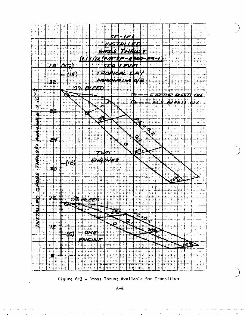
Figure 6-3 - Gross Thrust Avai l a b l e for T r a n s i t i o n
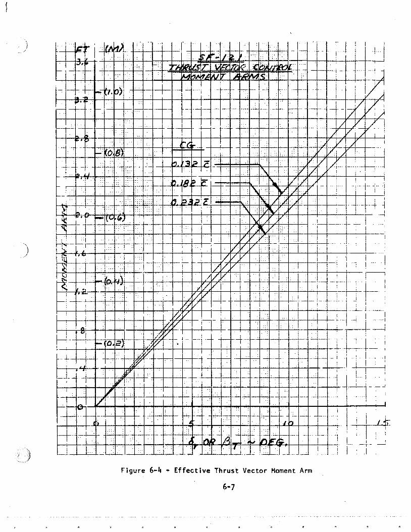
Figure 6-4 - Effective Thrust Vector Moment Arm 6-7
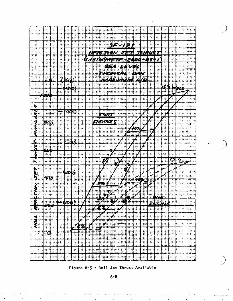
Figure 6-5 - Roll Jet Thrust Available
6-8
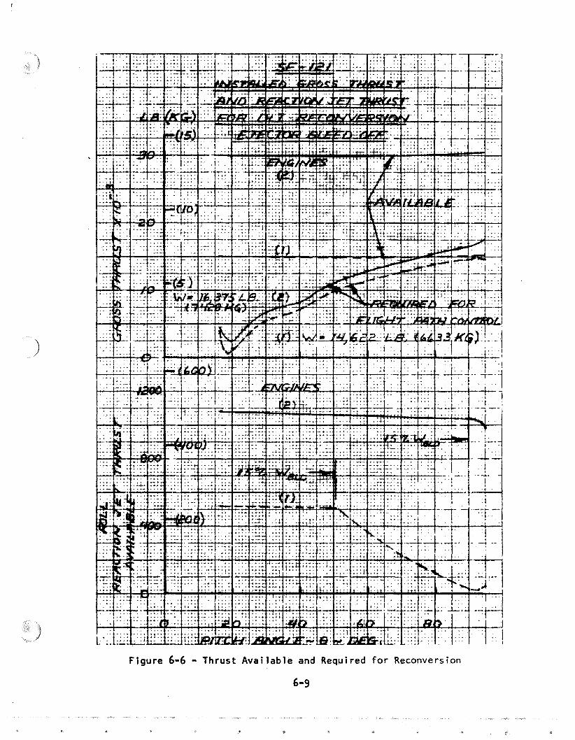
Figure 6-6 - Thrust Available and Required for Reconversion
re la t ionsh ips were constant a t a l l power set t ings. Figure 6-6 i l l u s t r a t e s
gross t h rus t ava i lab le versus required and react ion j e t th rus t ava i lab le
fo r design mission normal and s i ng le engine reconversions. Ample gross
and react ion j e t t h rus t i s ava i lab le f o r t h e normal DL1 design landing. Gross
and react ion j e t t h rus t f o r s i ng le engine hover i s inadequate due t o the
design T/W = 1.03 used f o r the SF-121 s iz ing. A h igher.design T/\J margin i s
recomnended. Hore complete descr ip t ion o f suggested design T/W f o r the
SF-121 type a i r c r a f t i s g iven i n Section 8.3.1.
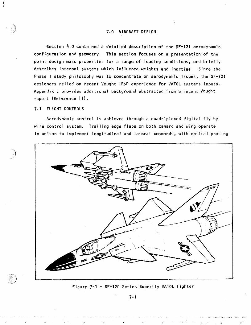
7.0 AIRCRAFT DESIGN
Section 4.0 contained a detailed description of the SF1121 aerodynamic
configuration and geometry. This section focuses on a presentation of the
point design mass properties for a range of loading conditions, and briefly
describes internal systems which influence weights and inertias. Since the
Phase I study philosophy was to concentrate on aerodynamic issues, the SF-121
designers relied on recent Vought IRED experience for VATOL systems inputs.
Appendix C provides additional background abstracted from a recent Vought
report (~eference 1 1 ) . 7.1 FLIGHT CONTROLS
Aerodynamic control is achieved through a quadriplexed digital fly by
wire control system. Trailing edge flaps on both canard and wing operate
in unison to implement longitudinal and lateral commands, with optimal phasing
Figure 7-1 - SF-120 Series Superfly VATOL Fighter 7- 1
throughout the f l i g h t envelope. F u l l span leading edge f l a p s a r e au tomat i ca l l y
phased t o ma in ta in the opt imal camber; the constant chord L.E. f l a p on the
h i g h l y tapered wing introduces p r o p o r t i o n a l l y g rea te r camber changes t o the
outboard reg ion t o enhance maneuver c h a r a c t e r i s t i c s . The inboard wing t r a i l i n g
edge forms s p l i t f l a p speedbrakes. The c e n t e r l i n e f i n has a conventional
rudder.
7.2 STRUCTURAL DES l GN
7.2.1 Wing and Empennage
The wings a t t a c h t o the s ides o f the fuselage and a re made almost
e n t i r e l y o f composite ma te r ia l s . I n s u l a t i o n i s requ i red around the supply
ducts t o the w i n g t i p r o l l j e t s t o p r o t e c t t he a f t wing box from h i g h tempera-
t u r e compressor bleed a i r . ( l n the o r i g i n a l design the a i r was ducted through
the elevons, which requ i red they be made o f t i t a n i u m and s t a i n l e s s s t e e l .)
The leading edge f l a p s a r e made from po ly imide/graph i te composite w i t h metal
e ros ion s t r i p s on the leading edges.
Canard and f i n a re genera l ly s i m i l a r t o the wing i n const ruc t ion ,
bu t a re l i g h t l y loaded and conta in minimum gauge mate r ia l s . They a l s o a t tach ""
d i r e c t l y t o the fuselage s t ruc tu re .
Fuselage
Length exc lus i ve o f the exposed exhaust nozzles i s 42.25 fee t .
The midsect ion i s a rec tangu lar box s t r u c t u r e d i v ided i n t o bays by bulkheads
which ca r ry ex terna l s tores, landing gear and wing bending loads. The exposed
wing panels a t t a c h t o lugs on the fuselage bulkheads. The space behind the
cockp i t conta ins the a f t av ion i cs bay and environmental c o n t r o l system compo-
nents. A f t o f t h i s sec t i on i s the weapons i n s t a l l a t i o n on the underside and
fue l tanks between and above the a i r i nduc t ion system. A s t r u c t u r a l f i r e w a l l
separates the engine compartments and d i s t r i b u t e s v e r t i c a l t a i l and engine
loads. A remote accessory package i s s h a f t d r i ven by both engines.
7.2.3 Fuel System
An i n f l i g h t r e f u e l i n g probe r e t r a c t s i n t o the topside o f the r i g h t
i n l e t nace l le . The probe extends up, o u t and forward w i t h the t i p i n c l e a r
view o f the p i l o t . The wing s t r u c t u r a l box i s an i n t e g r a l f u e l c e l l . Fuselage
fue l c e l l s extend from the nose gear bulkhead t o the engine ducts. A rear
f u e l c e l l can be located above the engines forward o f t he hot sec t ion . Th is
tank i s n o t requ i red t o conta in the 8,077 pounds o f JP-5 requ i red f o r the
SF-121 design miss ion.
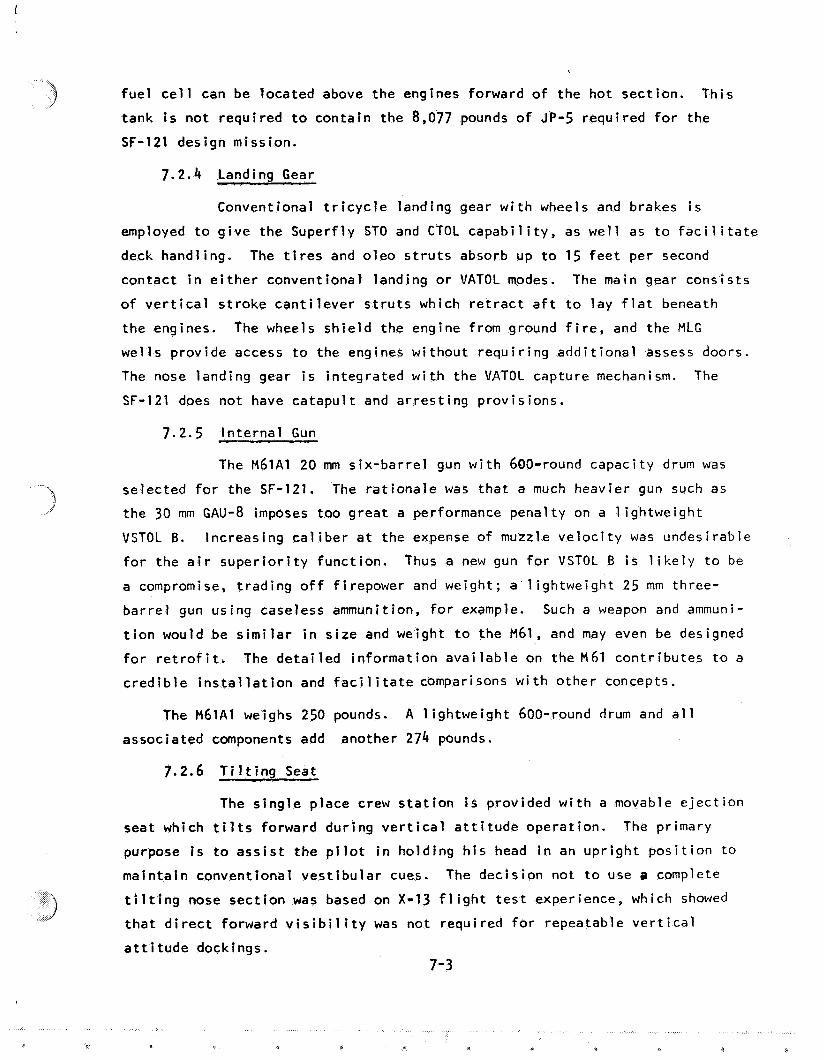
7.2.4 Landing Gear
Conventional t r i c y c l e landing gear w i t h wheels and brakes i s
employed t o g i v e the Super f ly ST0 and CTOL c a p a b i l i t y , as w e l l as t o f a c i l i t a t e
deck handl ing. The t i r e s and o l e o s t r u t s absorb up t o 15 f e e t per second
contac t i n e i t h e r conventional landing o r VATOL modes. The main gear cons is t s
o f v e r t i c a l s t roke c a n t i l e v e r s t r u t s which r e t r a c t a f t t o l ay f l a t beneath
the engines. The wheels s h i e l d the engine from ground f i r e , and the MLG
w e l l s p rov ide access t o the engines w i thou t r e q u i r i n g a d d i t i o n a l assess doors.
The nose land ing gear i s in tegra ted w i t h the VATOL capture mechanism. The
SF-121 does not have c a t a p u l t and a r r e s t i n g prov is ions .
7.2.5 I n t e r n a l Gun
The M61A1 20 mm s i x - b a r r e l gun w i t h 603-round capac i ty drum was
selected f o r the SF-121. The r a t i o n a l e was t h a t a much heavier gun such as
the 30 mm GAU-8 imposes too g rea t a performance pena l ty on a l i g h t w e i g h t
VSTOL B. Increasing c a l i b e r a t the expense of muzzle v e l o c i t y was undesi rable
f o r the a i r s u p e r i o r i t y func t ion . Thus a new gun f o r VSTOL B i s l i k e l y t o be
a compromise, t r a d i n g o f f f i repower and weight; a l i g h t w e i g h t 25 mrn th ree-
b a r r e l gun us ing caseless ammunition, f o r example. Such a weapon and amrnuni-
t i o n would be s i m i l a r i n s i z e and weight t o the M61, and may even be designed
f o r r e t r o f i t . The d e t a i l e d in format ion a v a i l a b l e on the M61 con t r i bu tes t o a
c r e d i b l e i n s t a l l a t i o n and f a c i l i t a t e comparisons w i t h o the r concepts.
The M61A1 weighs 250 pounds. A l i g h t w e i g h t 600-round drum and a l l
associated components add another 274 pounds.
7.2.6 T i l t i n g Seat
The s i n g l e p lace crew s t a t i o n i s provided w i t h a movable e j e c t i o n
seat which t i l t s forward dur ing v e r t i c a l a t t i t u d e opera t ion . The primary
purpose i s t o a s s i s t t he p i l o t i n ho ld ing h i s head i n an u p r i g h t p o s i t i o n t o
ma in ta in convent ional v e s t i b u l a r cues. The dec is ion not t o use a complete
t i l t i n g nose sec t i on was based on X-13 f l i g h t t e s t experience, which showed
t h a t d i r e c t forward v i s i b i l i t y was no t requ i red f o r repeatable v e r t i c a l
a t t i t u d e dockings. 7-3
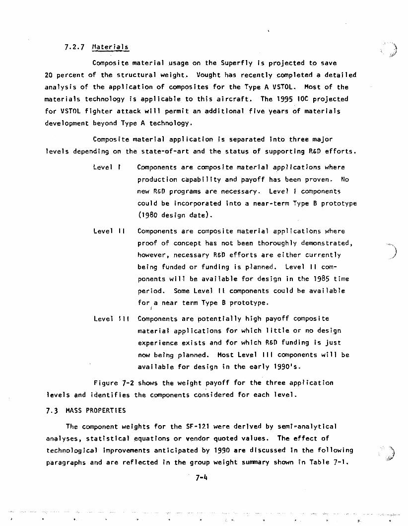
7.2.7 t !ater ia ls
Composite mater ia l usage on the Superf ly i s projected t o save
20 percent o f the s t r uc tu ra l weight. Vought has recent ly completed a de ta i l ed
analysis o f the app l i ca t ion o f composites f o r the Type A VSTOL. Most o f the
mater ia ls technology i s app l icab le t o t h i s a i r c r a f t . The 1995 I O C projected
f o r VSTOL f i g h t e r a t tack w i l l permit an add i t i ona l f i v e years o f mater ia ls
development beyond Type A technology.
Composite mater ia l app l i ca t ion i s separated i n t o three major
leve ls depending on the s ta te -o f -a r t and the status o f support ing RED e f f o r t s .
Level I Components are composite mater ia l app l ica t ions where
production capab i l i t y and payoff has been proven. No
new R&D programs are necessary. Level 1 components
could be incorporated i n t o a near-term Type I3 prototype
(1980 design date).
Level I t Components are composite mater ia l app l ica t ions where
proof of concept has not been thoroughly demonstrated,
however, necessary RED e f f o r t s a re e i t h e r cu r ren t l y
being funded o r funding i s planned. Level II com-
ponents w i l l be ava i lab le f o r design i n the 1985 time
period. Some Level I I components could be ava i lab le
f o r a near term Type B prototype. 1
Level I l l Components are p o t e n t i a l l y h igh payoff composite
mater ia l app l ica t ions f o r which l i t t l e o r no design
experience ex i s t s and f o r which RED funding i s j u s t
now being planned. Most Level I l l components w i l l be
ava i lab le f o r design i n the ea r l y 1990's.
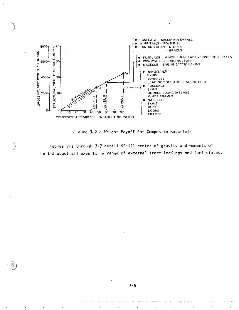
Figure 7-2 shows the weight payof f f o r the three app l i ca t ion
leve ls and i d e n t i f i e s the components considered f o r each leve l .
7.3 MASS PROPERTIES
The component weights f o r the SF-121 were dertved by sem l~ana l y t i ca l
analyses, s t a t i s t i c a l equations o r vendor quoted values. The e f f e c t o f
technological improvements an t i c ipa ted by 1990 are discussed I n the fo l lowing
paragraphs and are re f lec ted i n the group weight summary shown i n Table 7-1.
0 FUSELAGE - MAJOR BULKHEADS
I I 0 WINGITAILS - F O L D RIBS L A N D I N G GEAR - STHUTS
- B R A C t S z 2 + 0 FUSELAGE - MINOR RULhl iEADS - LONGF v 30.. LS - SUBSTHUC1 U R F 3 0 - ENGINE SECTION SKINS W u WINGITAILS
SURFACES W 3
L E A D I N G EDGE AND T R A I L I N G EDGE
J 0 FUSELAGE
u DOORSlFLOORS/SHE LVES M I N O R FRAMES NACELLE SKINS DUCTS DOORS . FRAMES
COMPOSITE ASSEMBLIES - %STRUCTURE WEIGHT
Figure 7-2 - Weight Payoff for Composite Materials
ROt:T, KEELS
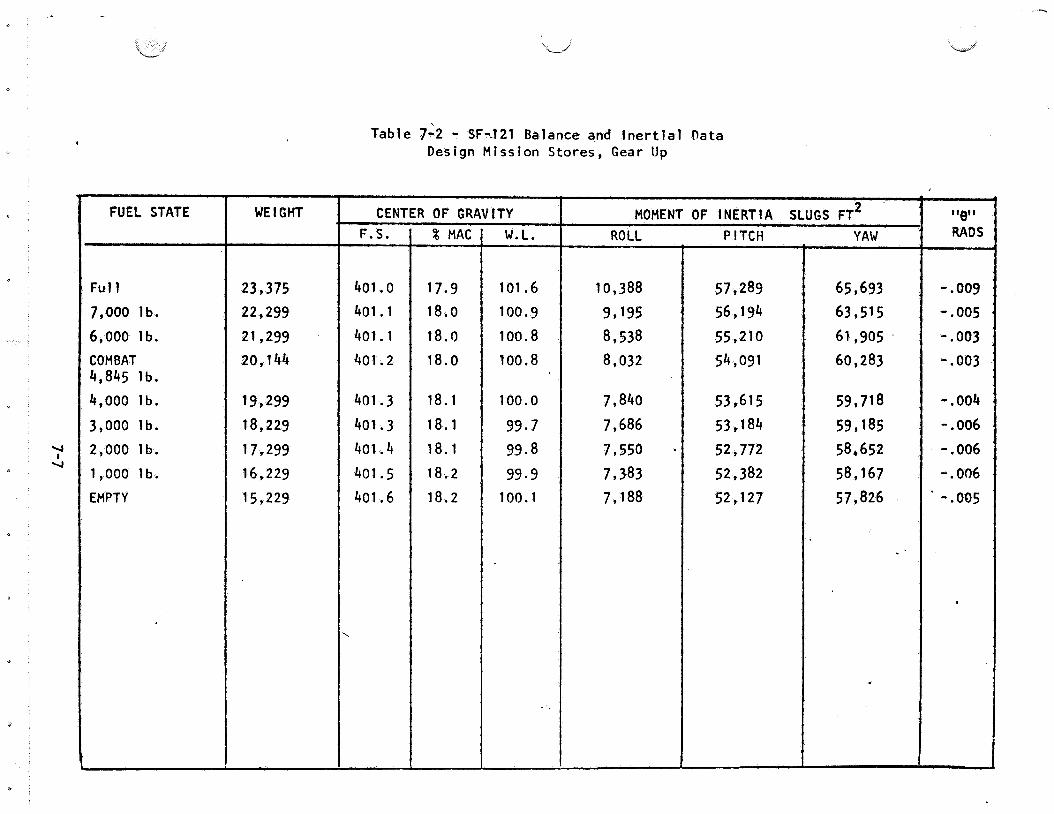
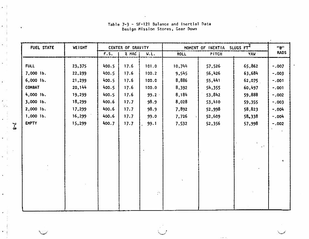
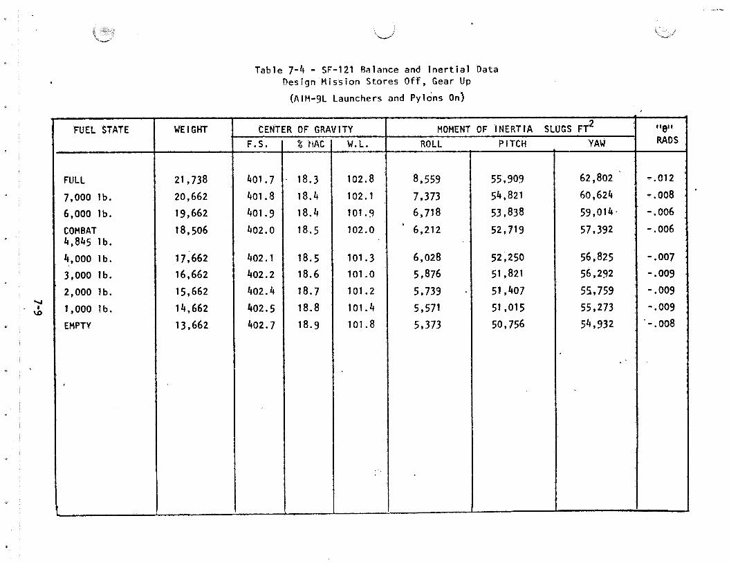
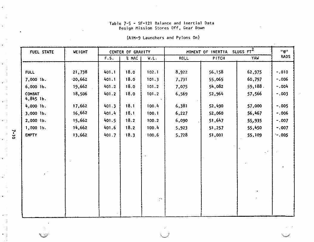
Tables 7-2 through 7-7 detail SF-121 center of gravity and moments of
inertia about all axes for a range of external store loadings and fuel states.
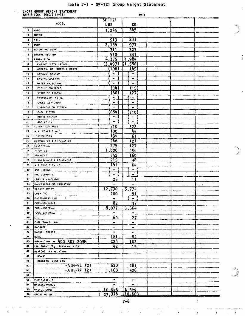
Table 7-1 - SF-121 Group Weight Statement
. bHORT CROUP WEIGHT STATEMENT MVAIR FORM I3090j3 (4-72) OATC
00
00
O
OO
CQ
0
00
0
00
00
0
..
a.
.
..
..
1
11
1
8 1
1 1
1
mL
nm
cr
\
OD
v\
hI
h\
D
m-
00
3
v-
OD
Ln
WN
\
OL
nc
nh
l
h-
\D
-0
0
........ .
..
..
L
nm
-0
m
ma
oa
l-
\
D\
D\
D\
O
Ln
Ln
Ln
Ln
Ln
cn
4-
0-
m
a-
WW
b
eo
cn
.--
cn
.
--
oo
-o
bw
N
-N
O
\D
v-
-c
r\
-
mm
m-
.
.m
..
a.
.
b\
DL
n*
M
mN
NN
L
nL
nL
nL
n
Ln
Ln
Ln
Ln
Ln
O3
Ln
WN
O
\D
Oc
r\
ao
"
*m
_O
_
cO
\D
Ln
m.
-
..
-.
.e
m
Oc
na
Oa
O
hh
hh
b
\Dc
nC
Da
o
Oh
ao
cn
-
..
..
.
..
..
.
--
00
0
oc
nc
nc
nc
0.
-.
--
hl
r
\m
;t
Ln
a
..
..
.
..
..
--.-.-
PP
.-
.-
.-
mc
nm
-t
c
nm
cn
cn
cn
-
mm
*
cn
NC
r\
NN
cr\
N
N
N
CJ
N
N
IN
.
..
..
.a
-
W
s t;; a W
3
lL
..
..
.
. .
nn
a
ma
n9
C
C
C
CC
CC
C-
oo
ai
no
oo
o>
-
00
m-
t0
00
0I
-
-o
mO
~a
oO
OO
Oc
L
21 -
0..
m
.. -
-=
L
Lh
8D
U.
ir
*M
Nr
-W
I J
hc
v\
-
Nn
?*
..
tN
.
c
OO
OC
OO
OO
OO
L
e
e
rO
rO
\O
\D
\D
hh
hh
. .
. . . . .
. .
mQ
\m
*m
Q\
or
mm
h
mm
*m
cn
mm
m
m,
N,
N*
U,c, N
* N
el
N N
mN
.-
O~
~~
\O
I~
N
NN
N-
.-
V-
.-
.-
W t
-2 G A
W 3
LL
. . .
..
.
0 9
C
C
PP
AA
C
CC
C
I- 0
0a
00
00
~
~0
0m
00
00
l-
-
10
0~
00
00
&
-0
*
a
a
..= L
Lh
\D
V*
WN
-W
1 A
mv, a
CC
I
c
U
-0 c
hl .-
=I .-VI
m
- o
- >
c't
L
m 't 0
TI aJ
C
urn
m
C
aJ m
~
m
-0
I
mu
Q
) am r
U
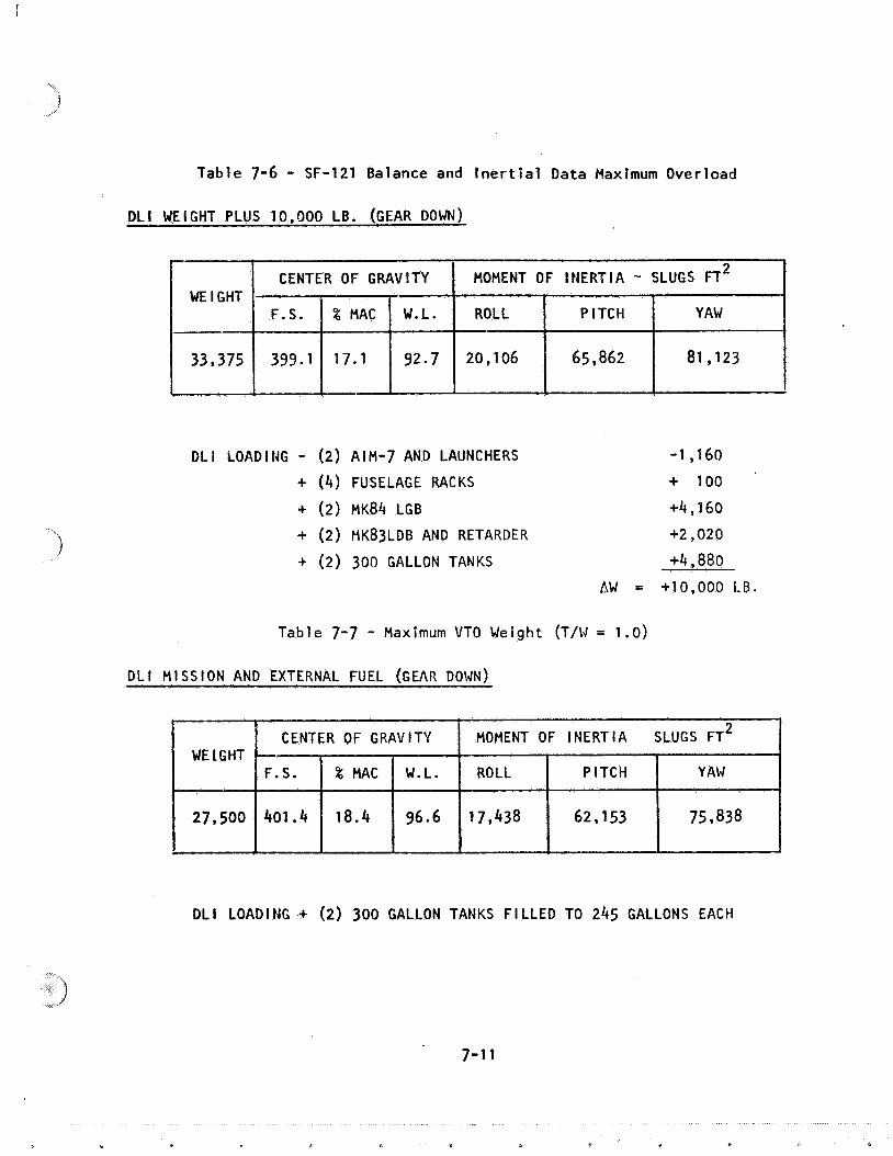
Table 7-6 - SF-121 Balance and I n e r t i a l Data Maximum Overload
DL1 WEIGHT PLUS 10,000 LB. (GEAR DOWN)
DL1 LOADING - (2) A IM-7 AND LAUNCHERS -1,160
+ (4) FUSELAGE RACKS + 100
+ (2) ~ K 8 4 LGB +4,160
+ (2) MK83LDB AND RETARDER +2,020
+ (2) 300 GALLON TANKS +4,880
bW = +10,000 L B .
Table 7-7 - Maximum VTO Weight (T/w = 1.0)
WE l GHT
33,375
L
DL1 M I S S l O N AND EXTERNAL FUEL (GEAR DOWN)
MOMENT OF INERTIA - SLUGS F T ~
DL I LOAD lNG + (2) 300 GALLON TANKS F l LLED TO 245 GALLONS EACH
ROLL
20,106
CENTER OF GRAVITY
P ITCH
65,862
W.L.
92.7
F.S.
399.1
YAW
81,123
% MAC
17.1

8.0 SF-121 PERFORMANCE
8.1 POINT DESIGN
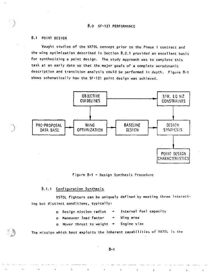
Vought studies of the VATOL concept prior to the Phase I contract and
the wing optimization described in Section 8.2.1 provided an excellent basis
for synthesizing a point design. The study approach was to complete this
task at an early date so that the major goals of a complete aerodynamic
description and transition analysis could be performed in depth. Figure 8-1 shows schematically how the SF-121 point design was achieved.
Figure 8-1 - Design Synthesis Procedure
8.1.1 Configuration Synthesis
VSTOL fighters can be uniquely defined by meeting three interact-
ing but distinct conditions, typically:
o Design mission radius + Internal fuel capacity
o Maneuver load factor + Wing area
o Hover thrust to weight + Engine size
The mission which best exploits the inherent capabilities of VATOL is the
Supersonic l n te rcep t (neck Launched In te rcep t ) . Dispersed basing has the
e f f e c t o f reducing requ i red radius o f a c t i o n and dash Hach number. For t h i s
study the Supersonic In te rcep t design miss ion p r o f i l e was s p e c i f i e d t o have
a 150 NM rad ius w i t h a Mach 1.6 40,000 foo t outbound dash. These values have
been used i n o the r VSTOL s tud ies i n recent years and w i l l f a c i l i t a t e compari-
sons w i t h o the r concepts.
The o b j e c t i v e gu ide l i nes i n the Request f o r Proposal inc luded a
sustained 6.2 g maneuver c o n s t r a i n t a t Mach 0.6 10,000 fee t . Vought selected
a t h r u s t t o weight o f 1.03 f o r s i n g l e engine hover as the t h i r d s i z i n g condi-
t i o n . I t was imposed a t a weight corresponding t o 1,000 pounds f u e l , 400
rounds o f 20 mm ammunition, bu t no ex te rna l s tores. Thrust r a t i n g was
maximum a f te rbu rne r , 89.6'~, w i t h minimum coo l i ng a i r b leed but no contingency
r a t i n g . The 1.03 value was recommended by the Navy f o r Type A VSTOL s tud ies .
La te r ana lys i s addressed the s u i t a b i l i t y o f t h i s c r i t e r i o n .
The SF-121 p o i n t design which meets the th ree s i z i n g c r i t e r i a was
determined using the Vought A i r c r a f t Synthesis Analys is Program (ASAP),
F igure 8-2 ASAP in te r faces the techn ica l d i s c i p l ines (weights, propuls ion,
aerodynamics and performance) and creates a design space f o r a s p e c i f i e d
m a t r i x o f con f igu ra t i on var iab les . The CDC 6600 i n t e r a c t i v e computer graphics
f a c i l i t y d i sp lays the r e s u l t s . The minimum weight a i r p l a n e which s a t i s f i e s a l l
missions and c o n s t r a i n t s w i t h i n the design space can then be selected by the
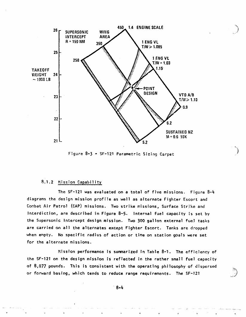
designer and machine p l o t t e d . F igure 8-3 shows the weight carpet f o r the
SF-121. A l l n ine combinations of wing area and engine scale f a c t o r a re f u e l
balanced t o a 150 NM rad ius on the design mission. It i s seen t h a t on l y
designs w i t h a wing area o f 350 square f e e t o r g reater s a t i s f y the 6.2 g
maneuver cons t ra in t . The se lec ted p o i n t design I s de f ined by the i n t e r s e c t i o n
o f the maneuver and thrust /weight = 1.03 boundaries, y i e l d i n g :
o Takeoff gross weight = 23,375 l b . (10,603 kg) 2
o Wing reference area = 350 f t 2 (32.56 m )
o Engine sca le = 1.131 R a t i o t h r u s t per engine = 16,965 l b t
(75,464 N)
The c a p a b i l i t i e s o f t h i s p o i n t design w i l l be explored i n the f o l l o w i n g
sect ions.
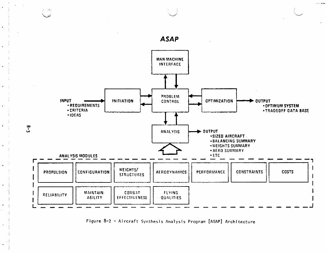
ASAP
M A N . M A C H I N E INTERFACE
OUTPUT * O P T I M U M SYSTEM * T R A D E O F F O A T A BASE
* I D E A S
ANALYSIS
Lcrr OUTPUT
*SIZED A I R C R A F T * BALANCING S U M M A R Y *WEIGHTS S U M M A R Y
AERO SUMMARY ANALYSIS h1ODULES * ETC r..l.II,-.lll-.l.---...-.L----.L.----..II -------.I---- -7
RELIABIL ITY E F F E C I I V E N E S S Q U A l l T l E S
F igure 8-2 - A i r c r a f t Synthesis Analysis Program [ASAP] Arch i tecture
TAKEOFF WEIGHT 24 - 1000 LB
.4 ENGINE SCALE SUPERSONIC INTERCEPT
SUSTAINED N Z M = 0.6 10K
SUPERSONIC INTERCEPT R = 150 NM
Figure 8-3 - SF-121 Parametric Siz ing Carpet
Mission Capabi l i ty
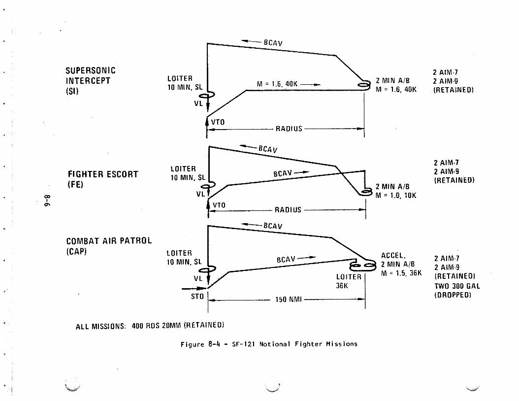
The SF-121 was evaluated on a t o t a l o f f i v e missions. Figure 8-4
diagrams the design mission p r o f i l e as we l l as a l te rna te F ighter Escort and
Combat A i r Pat ro l (CAP) missions. Two s t r i k e missions, Surface S t r i ke and
In te rd ic t ion , are described i n Figure 8-5. In terna l fue l capacity i s set by
the Supersonic In tercept design mission. Two 300 ga l lon external f ue l tasks
are ca r r ied on a l l the a l ternates except F ighter Escort. Tanks are dropped
when empty. No spec i f i c radius o f ac t ion o r time on s t a t i o n goals were set
fo r the a l t e rna te missions.
Mission performance i s summarized i n Table 8-1. The e f f i c i ency o f
the SF-121 on the design mission i s r e f l ec ted i n the ra ther small f ue l capacity
o f 8,077 pounds. This i s consistent w i t h the operat ing philosophy o f dispersed
o r forward basing, which tends t o reduce range requirements. The SF-I21
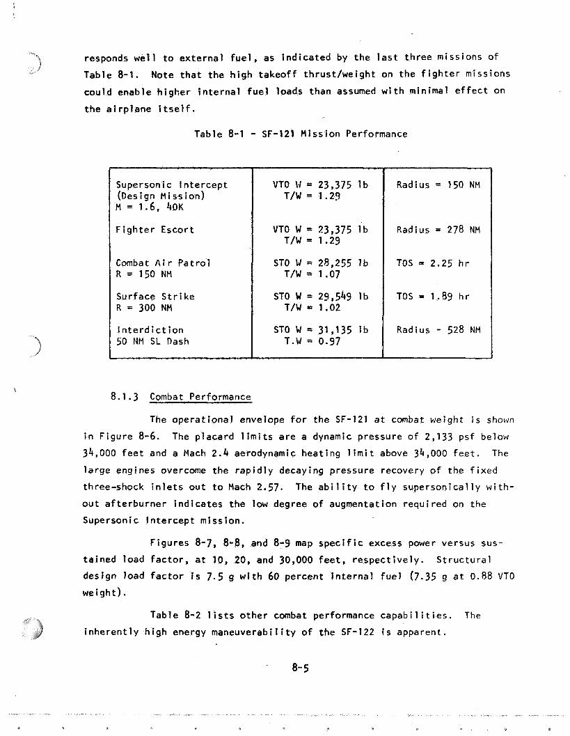
responds w e l l t o ex te rna l f ue l , as i nd i ca ted by the l a s t th ree missions of
Table 8-1. Note t h a t t he h i g h takeo f f th rus t /we ight on the f i g h t e r missions
cou ld enable h igher i n t e r n a l f u e l loads than assumed w i t h minimal e f f e c t on
the a i r p l a n e i t s e l f .
Table 8-1 - SF-121 Miss ion Performance
8.1.3 Combat Performance
The opera t iona l envelope f o r the SF-121 a t combat weight i s shown
i n F igure 8-6. The p lacard l i m i t s a r e a dynamic pressure o f 2,133 ps f below
34,000 f e e t and a Mach 2.4 aerodynamic heat ing l i m i t above 34,000 f e e t . The
la rge engines overcome the r a p i d l y decaying pressure recovery o f the f i x e d
three-shock i n l e t s o u t t o Mach 2.57. The a b i l i t y t o f l y superson ica l ly w i t h -
o u t a f te rbu rne r i nd i ca tes the low degree o f augmentation requ i red on the
Supersonic l n te rcep t mission.
Supersonic In te rcep t ( ~ e s i g n Miss ion) M = 1.6, 40K
F i g h t e r Escort
Combat A i r P a t r o l R = 150 NM
Surface S t r i k e R = 300 NM
I n t e r d i c t i o n 50 NM SL Dash
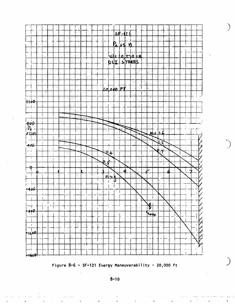
Figures 8-7, 8-8, and 8-9 map s p e c i f i c excess power versus sus-
ta ined load fac tor , a t 10, 20, and 30,000 f e e t , respec t i ve l y . S t r u c t u r a l
design load fac to r i s 7.5 g w i t h 60 percent I n t e r n a l f u e l (7.35 g a t 0.88 VTO
weight) .
Table 8-2 l i s t s o the r combat performance c a p a b i l i t i e s . The
i nhe ren t l y h i g h energy maneuverabi l i ty o f the SF-122 i s apparent.
VTO H = 23,375 l b T/W = 1.29
VTO W = 23,375 1 b T/W = 1.29
ST0 W = 28,255 l b T/W = 1.07
ST0 W = 24,549 l b T/W = 1.02
ST0 W = 31,135 l b T.W = 0.97
Radius = 150 NM
Radius = 278 NM
TOS = 2.25 h r
TOS = 1.89 h r
Radius - 528 NM
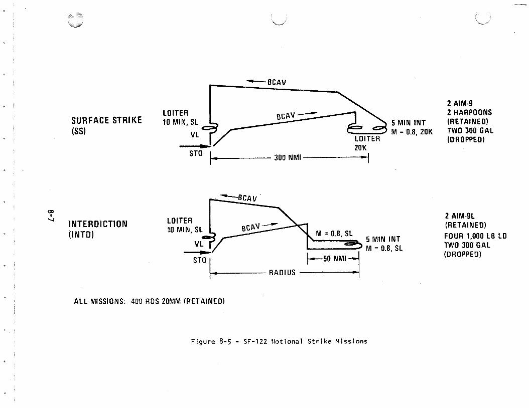
2 AIM-9 2 HARPOONS
SURFACE STRIKE 5 MIN INT (RETAINED) 6 s ) M = 0.8, 20K TWO 300 GAL
(DROPPED)
Q3 I
INTERDICTION (INTO)
LOITER 10 MIN, S
v k 5 0 NMI-
C
ALL MISSIONS: 400 RDS 20MM (RETAINED)
5 MIN INT M = 0.8, SL
2 AIM-9L (RETAINED) FOUR 1,000 LB LO TWO 300 GAL (DROPPED)
F igure 8-5 - SF-122 t lotional S t r i k e M iss ions
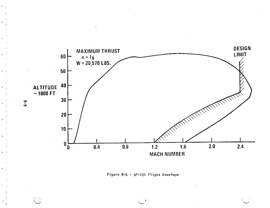
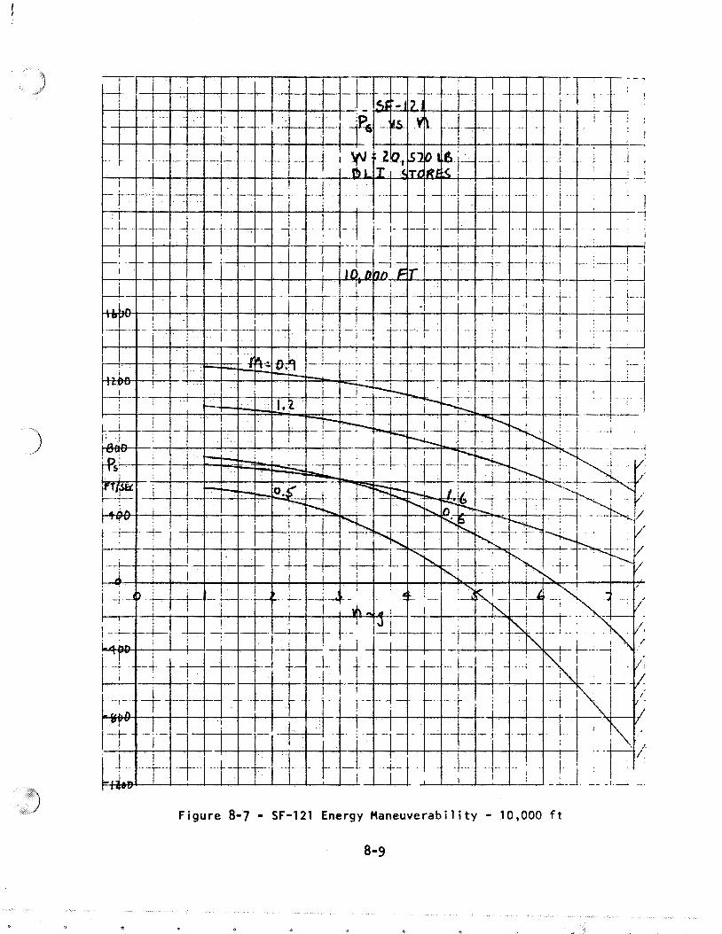
Figure 8-7 - SF-121 Energy Haneuverability - 10,000 f t
8-9
. -
Figure 8-6 - SF-121 Energy Maneuverability - 20,080 f t
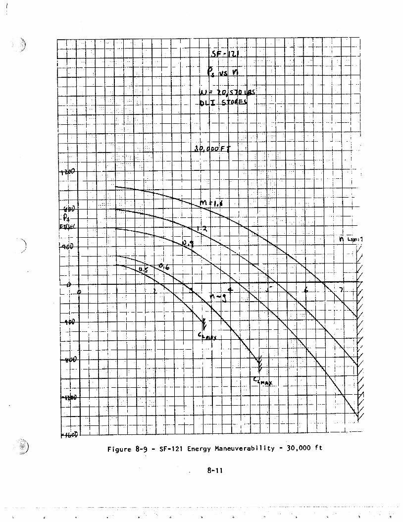
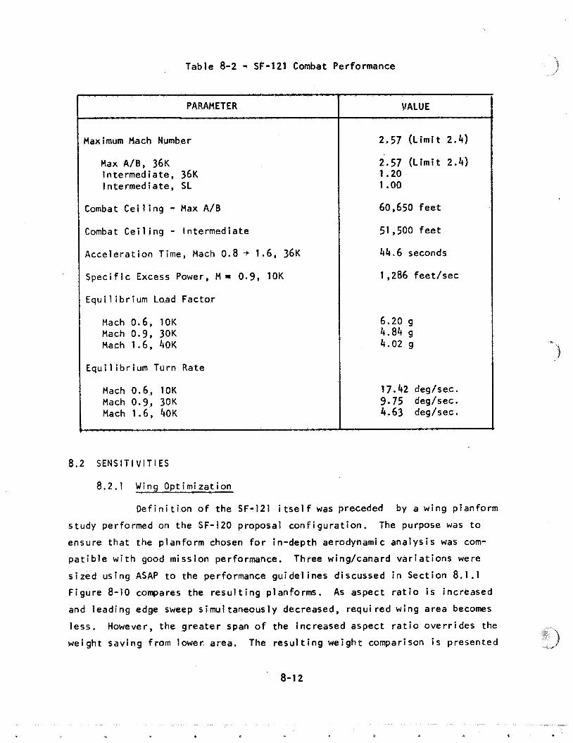
Table 8-2 - SF-121 Combat Performance
8.2 SENSITIVITIES
Maximum Mach Number 2.57 ( L i m i t 2.4)
2.57 ( ~ l m i t 2.4) Intermediate, 36K Intermediate, SL
Combat C e i l i n g - Max A/B
Combat C e i l i n g - Intermediate
Acce lera t ion Time, Mach 0.8 -t 1.6, 3 6 ~ 44.6 seconds
S p e c i f i c Excess Power, M - 0.9, 10K 1,286 feet /sec
E q u i l i b r i u m Load Factor
Mach 0.6, 10K
8.2.1 Wing Opt imizat ion
D e f i n i t i o n o f the SF-121 i t s e l f was preceded by a wing p lanform
study performed on the SF-120 proposal con f igu ra t i on . The purpose was t o
ensure t h a t the p l anfo r m chosen f o r in-depth aerodynami c ana lys is was com-
p a t i b l e w i t h good mission performance. Three wing/canard va r ia t i ons were
s i zed using ASAP t o the performance gu ide l ines discussed i n Sect ion 8.1.1
Figure 8-10 compares the r e s u l t i n g planforms. As aspect r a t i o i s increased
and leading edge sweep s imul taneous 1 y decreased, requi red wing area becomes
less. However, the greater span o f the increased aspect r a t i o over r ides the
weight saving from lower. area. The r e s u l t i n g weight comparison i s presented
Mach 0.9, 30K Mach 1.6, 40K
Equ i l i b r i um Turn Rate
Mach 0.6, 1OK Mach 0.9, 30K Mach 1.6, 40K
i
4.84 g 4.02 g
17.42 deg/sec. 9.75 deg/sec. 4.63 deglsec.
4
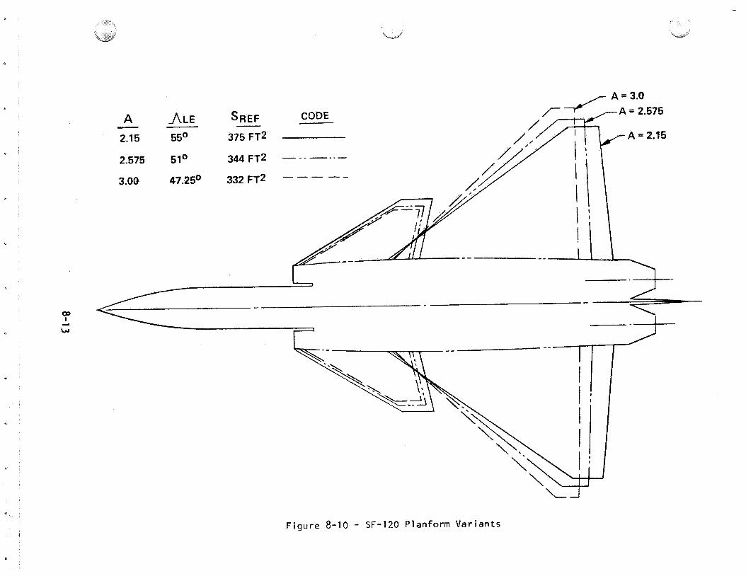
A CODE - ALE - SREF 7
F i g u r e 8-10 - SF-120 Planform Var iants
i n F igure 8-11. It i s seen t h a t t he opt imal aspect r a t i o i s about 2.3, and
t h a t "high" values such as 3.0 y i e l d h igher takeo f f weight. 1
This i s a s i g n i f i c a n t r e s u l t . CTOL f i g h t e r s usua l l y b e n e f i t from
aspect r a t i o s as h i g h as 4.0. But the premium placed on low empty (or landing)
weight makes a l i g h t wing more va luab le than one w i t h lower drag due t o l i f t .
On the Supersonic In te rcep t miss ion the aspect r a t i o 2.3 wing a l s o has low
supersonic drag, which re in fo rces i t s s u p e r i o r i t y .
Previous wing s tud ies have shown taper r a t i o t o be a second order
parameter. The o r i g i n a l va lue o f 0.1 was increased t o 0.15 f o r t he SF-121 t o
increase ou te r panel elevon chord and prov ide more space f o r hover reac t ion
j e t r o l l con t ro l s . Another study showed a wing th ickness r a t i o o f e i t h e r 5 o r 6 percent t o g i v e equal performance. The th inne r wing was chosen t o
permi t supersonic dash a t s l i g h t l y lower augmentation t o reduce i n f r a r e d
s ignature.
8.2.2 Const ra in t Va r ia t i ons
The standard ASAP synthesis procedure y i e l d s a weal th o f pe r fo r - m
mance s e n s i t i v i t y data r e l a t i n g the pr imary design va r iab les and cons t ra in ts .
Appendix D conta ins t h i s backup data f o r the SF-121 and exp la ins how t o use
i t t o determine the weight and performance consequences o f a l t e r n a t i v e s i z i n g
c r i t e r i a .
8.3 TRANS IT l ON PERFORMANCE
Trans i t ions from hover t o convent i ona l f 1 i g h t (convers ions) and conven-
t i o n a l t o hover f l i g h t (reconversions) have been simulated f o r the SF-121
p o i n t design. Var iables evaluated inc lude weight, f l i g h t path angle, decelera-
t i o n r a t e and a i r c r a f t s t a t i c margin. Time h i s t o r i e s show: h o r i z o n t a l and
v e r t i c a l p o s i t i o n and angle; a i r c r a f t angles o f a t t a c k and p i t c h ; aerodynamic
fo rces and moment; t h r u s t required; and t r i m t h r u s t d e f l e c t i o n . Conversion
t ime t o Mach 0.3 was rap id , b u t ref inements a r e needed f o r f l i g h t path c o n t r o l .
Reconversion t ime and t h r u s t requ i red evidenced much v a r i a t i o n due t o technique
and s t a t i c margin. S ing le engine reconversions were poss ib le o n l y over a very
narrow band o f opera t ing cond i t ions determined by t h r u s t ava i l ab le . A t h i n
aerodynamic data base precluded eva lua t ion o f c o n f i g u r a t i o n e f f e c t s which
could reduce t ime i n t r a n s i t i o n . *-
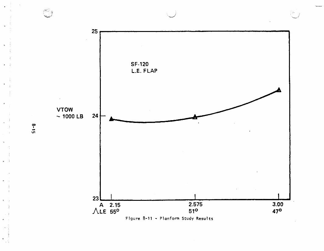
SF-120 L.E. FLAP
VTOW - 1000 LB
A 2.15 2.575 ALE 550 51°
Figure 8-11 - Planform Study Results
The analys is c l e a r l y showed t ha t the engine s i z i n g c r i t e r i o n o f th rus t /
weight = 1.03 f o r the s ing le engine v e r t i c a l landing made t r ans i t i ons t o hover
d i f f i c u l t and marginal. E i the r a larger engine o r a short term r a t i n g g i v i ng
a T/W - > 1.086 i s necessary t o meet M IL-F-83300 Level 2 con t ro l powers. Most
o f the problems discussed i n t h i s sect ion apply t o the T/\J = 1.03 s i z i ng
cons t ra in t and can be a l l ev i a ted by increased t h rus t ava i lab le .
Maximum ava i l ab le con t ro l power was determined f o r two types o f a t t i t u d e
con t ro l systems. The basic system included t h rus t vector ing con t ro l f o r
p i t c h and yaw and react ion j e t r o l l control . An a l t e rna te system using reac-
t i o n cont ro l about a l l axes was compared t o the basic system. Results showed
the basic system t o be d i s t i n c t l y superior. Maximum con t ro l power and con t ro l
s e n s i t i v i t y compared favorably t o MIL-F-83300 and AGARD 577 requirements.
Revised design th rus t t o weight margins have been postulated as a r e s u l t of
these studies. Neither system studied provided enough con t ro l power t o t r i m
out 15 degrees s i d e s l i p a t a > 26 degrees i n t r ans i t i on . This was due t o
h igh ly unstable d i r ec t i ona l s t a b i l i t y estimated f o r the basic SF-121 configura- - t i on . Conf igurat ion development tes t ing t o reduce o r e l iminate t h i s problem
i s indicated.
T rans i t i on ro l l /yaw con t ro l phasing o f r o l l react ion j e t t h rus t and yaw
con t ro l th rus t vector de f l ec t i on w i t h a i r c r a f t p i t c h a t t i t u d e was evaluated.
Opposite ax is coupl ing was negated f o r t h i s study. The phasing schedule was
developed t o keep the p i l o t ' s conventional f l i g h t cockp i t cont ro ls inputs and
o r i en ta t i on w i t h the horizon compatible through t r a n s i t i o n i n t o hover. Thus,
p i l o t workload and t r a i n i n g time would be reduced. I n conventional f l i g h t
rudder provides yaw and s t i c k provides r o l l . During v e r t i c a l a t t i t u d e hover
s t i c k provides yaw and rudder provides r o l l . To determine the t r a n s i t i o n
phasing, intermediate i n e r t i a s were computed, con t ro l requirements were esta-
bl ished, and required con t ro l input phasing was calculated. Results indicated
that r o l l and yaw coup1 ing was favorable a t intermediate p i t c h angles (i .e.,
nose r i g h t yaw con t ro l induced nose r i g h t yaw). Proper blending o f these
cont ro ls could s i g n i f i c a n t l y reduce the maximum s ing le ax is con t ro l power
required (e.g., react ion j e t th rus t and/or t h rus t vector de f lec t ion ) .
Further study i s needed t o set minimum requirements f o r con t ro l
power and consequent design th rus t t o weight leve ls . Thrust vector ing appeared
a t t r a c t i v e f o r two engine operat ion r o l l cont ro l but a scheme fo r single-engine
r o l l con t ro l sans reac t ion j e t was not read i l y apparent. Proper assessment o f
the emergency landing i s c r i t i c a l t o assure a sa t i s fac to ry design so lu t ion.
8.3.1 Landing Trans i t i on
The ob jec t i ve o f the t r a n s i t i o n analyses was t o evaluate \!ATOL
reconversion and conversion f l i g h t paths. Selected f l i g h t paths required
adequate height and a t t i t u d e cont ro l w i t h minimum impact on engine size, VTO
gross weight and p i l o t workload. Reconversion was much more d i f f i c u l t because
o f t h r o t t l e excursions combined w i t h p i t c h and s ink r a t e con t ro l during
decelerat ion and descent. P r o f i l e s were based on X-13 V e r t i j e t f l i g h t t e s t
experience (~eferences 12 and 13). Re la t i ve ly s t ra ight forward p r o f i l e s
including a constant p i t c h r a t e leve l decelerat ion t o s t a l l , a higher
constant p i t c h ra te leve l decelerat ion t o near v e r t i c a l a t t i t u d e , and a des-
cending o r leve l decelerat ion t o an in tercept were developed. Control v a r i -
ables were p i t c h r a t e and r a t e o f s ink as a funct ion o f ve loc i t y . Reconver-
sions were assessed f o r the basic unstable and s tab le two engine landings and
the unstable single-engine emergency landing. Normal two-engine reconversions
from approach speed (1.3 vSpA) t o a landing in tercept (5 f t l s e c forward
ve loc i t y and 3 f t / sec s ink ra te) were achieved i n 37.6 t o 46.8 seconds.
S imi lar r esu l t s were shown f o r leve l decelerat ions ending a t 5 f t / sec forward
ve loc i t y . Thrust required and a t t i t u d e ca lcu la ted f o r the reconversions were
used as a basis fo r the cont ro l power and phasing studies discussed i n
Sections 8.3.3 and 8.3.4.
A l l reconversions were ca lcu la ted on a quasi-steady ( i .e., no Z
ax is acce lera t ion forces) basis using conventional l ong i tud ina l three degree
o f freedom equations o f motion (see Figure 8-12). To e f f e c t so lu t ion, an
i n i t i a l angle o f a t tack, ve loc i t y , p i t c h rate, and r a t e o f s ink p r o f i l e and
maximum p i t c h angle were speci f ied. Ve r t i ca l fo rce and moment balance was
required f o r each po in t (t ime i n te r va l ) calculated. Net def ic iency i n
hor i zon ta l fo rce was output as a decelerat ion and was integrated t o g ive
ve loc i t y and p o s i t i o n along the f l i g h t path. Ve r t i ca l pos i t i on was integrated
from r a t e o f s ink. The force and moment balance resu l ted i n thrust required
and th rus t de f l ec t i on needed t o t r i m . Thus, th rus t de f l ec t i on required t o
8-1 7
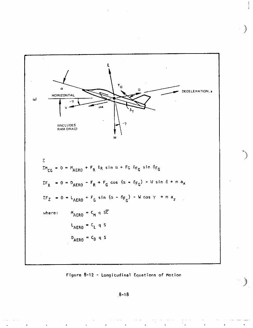
C
L H ~ ~ = O = MAERo + FR !LR s i n a + FG 2~~ s i n 6~~
CFX 0 = DAERO - F R + F G cos (a - tiFG) - V s i n 6 + m ax
CFZ 0 = LAERO + FG s i n (a - 6 ~ ~ ) - W cos Y + m a z
- where: M~ ERO = CM q SC
L~~~~ = 'L q
DAERO = 'D 9
DECELERATION, a
(INCLUDES RAM DRAG)
W
F igure 8-12 - Longitudinal Equations o f Motion
8-1 8
main ta in o r es tab l i s h p i t c h r a t e was no t inc luded i n the r e s u l t s . Hand
c a l c u l a t i o n s i n d i c a t e d t h a t a 3 degree t h r u s t d e f l e c t i o n would be requ i red t o
i n i t i a t e the maximum 5 deg/sec p i t ch r a t e used f o r these ca l cu la t i ons . Much
less woul d be requi red t o overcome aerodynami c damping, which was no t est imated.
Aerodynamic data used f o r t r a n s i t i o n analyses i s presented i n
F igures 5--13, 5-14 and 5-15. The d e r i v a t i o n o f t h i s data appears i n Appen-
d i x A. For the t r a n s i t i o n analyses, aerodynamic e levon t r i m w a s assumed t o be
a v a i l a b l e up t o +20 degrees e levon d e f l e c t i o n , Maximum elevon was l i m i t e d t o
+ 20 degrees u n t i 1 the end o f the t r a n s i t i o n t o assure an adequate margin o f - elevon d e f l e c t i o n f o r r o l l c o n t r o l . Landing gear drag (A CDGEAR = 0.0200) and
s t o r e drag (A cDSTORES = 0.0024) were added t o the trimmed drag. Store drag
was de le ted f o r the s i n g l e engine v e r t i c a l landing.
Reconversions were pa t te rned a f t e r X-13 Ver t i j e t f l i g h t t e s t re-
s u l t s (Reference 13) . Reconversion was i n i t i a t e d a t 1.3 V (a > 16.4 SPA -
degrees) w i t h a slow p i t c h r a t e o f 0.8 - 1.2 deg/sec. V e r t i c a l f o rce balance
requ i red t o main ta in l e v e l f l i g h t l i m i t e d p i t c h r a t e t o t h a t which would y i e l d
t h r u s t reduct ions t o i d l e . Average dece le ra t i on t o s t a l l was 2 t o 3 kts/sec.
A t s t a l l , a p i t c h r a t e o f 5 deg/sec was commanded and h e l d u n t i l a s p e c i f i e d
maximum p i t c h angle ( 0 ) was reached. P i t c h ra tes less than f i v e degrees per
second caused s i g n i f i c a n t increases i n dece le ra t i on t ime. Sustained p i t c h
ra tes exceeding 5 deg/sec would reduce t r a n s i t i o n t ime b u t cou ld be q u i t e
uncomfortable f o r t he p i l o t . A l l descending p r o f i l e s i n i t i a t e d s i n k r a t e a t
80 f t / s e c forward v e l o c i t y . Maximum s i n k r a t e was 12 f t / s e c f o r two-engine
descents and 3 f t / s e c f o r one-engine descents. A summary o f reconversion
performance i s presented i n Table 8-3. Thrust a v a i l a b l e f o r reconversion and
conversion i s tabu la ted i n Table 8-4. Reconversion t ime h i s t o r i e s f o r the
SF-121 p o i n t design are presented i n F igure 8-13 (normal two engine) , and i n
F igure 8-14 f o r the s i n g l e engine case.
Two engine reconversions were genera l l y uncomplicated. Time and
d is tance t o land ing i n t e r c e p t was reduced by increas ing the maximum a l lowab le
angle o f a t t a c k beyond 90 degrees. Th i s maneuver increased b rak ing t h r u s t
requ i red near the end o f t r a n s i t i o n . The h ighe r b rak ing t h r u s t requ i red s t i l l
l e f t ample margin a t t i t u d e and he igh t c o n t r o l (See Table 8-3). Fuel
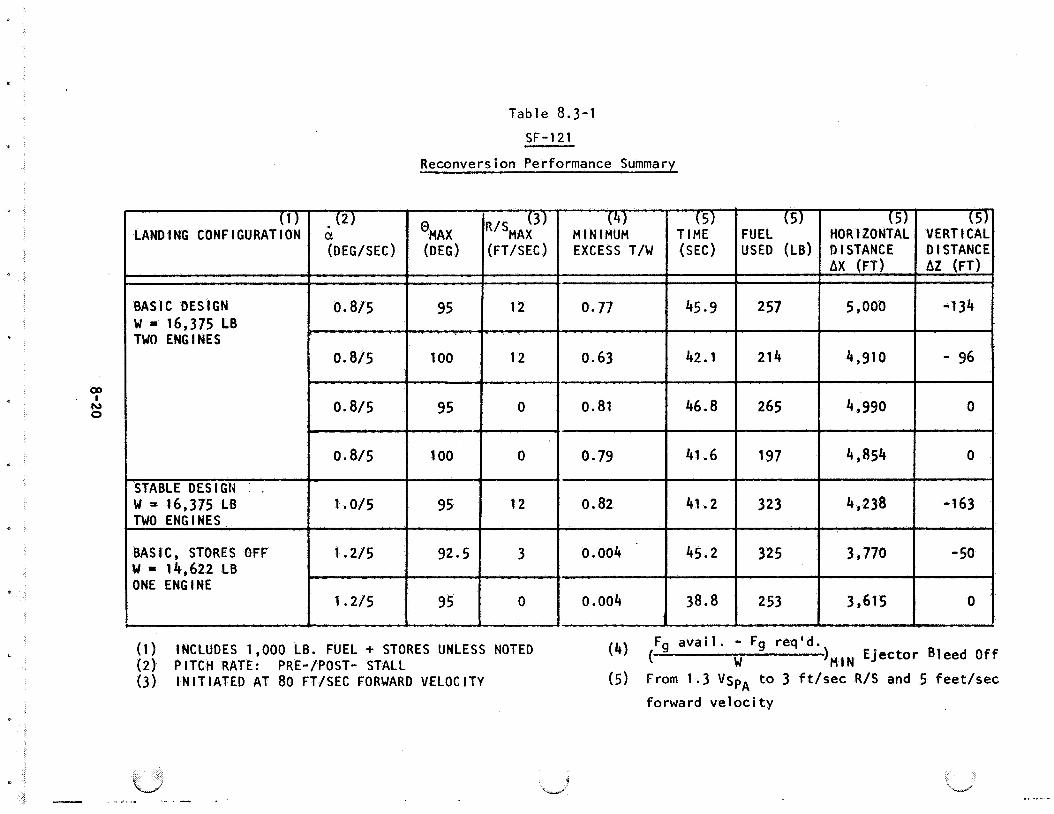
Table 8.3-1
Reconversion Performance Summary
LANDING CONFIGURAT
BASIC DESIGN
TWO ENGINES
BASIC, STORES OFF
(1) INCLUDES 1,000 LB. FUEL + STORES UNLESS NOTED (2) PITCH RATE: PRE-/POST- STALL (3) INITIATED AT 80 FT/SEC FORWARD VELOCITY
(4) ( Fg a v a i l . - Fg req 'd .
w )HI N E j e c t o r Bleed O f f
(5) From 1 .3 VspA t o 3 f t l s e c R/S and 5 feet /sec
forward v e l o c i t y
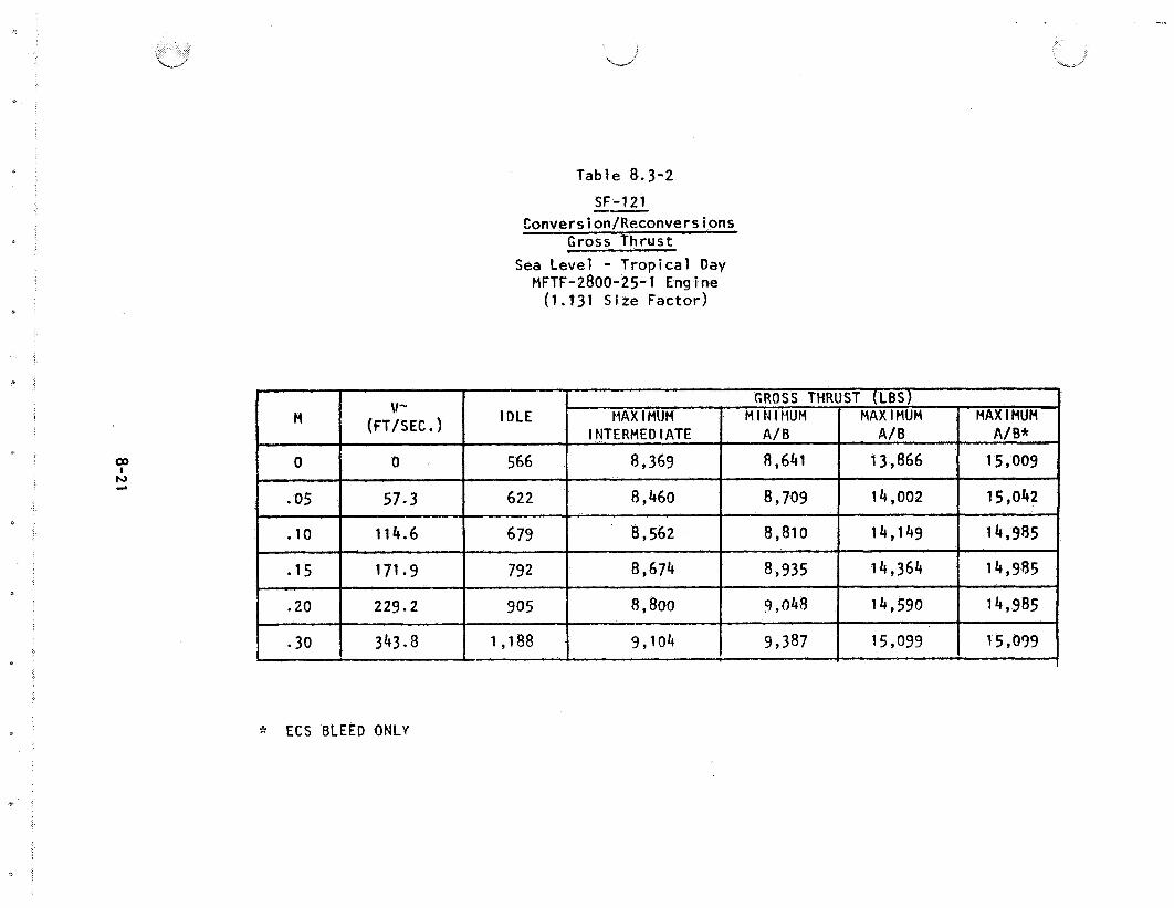
Table 8.3-2
SF-121 -7
Conversion/Reconversions Gross Thrust
Sea Level - Tropical Day MFTF-2800-25-1 Engine (1.131 Size actor)
* ECS BLEED ONLY
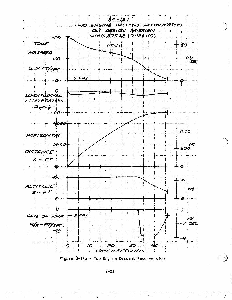
Figure 8-13a - Two Engine Descent Reconversion
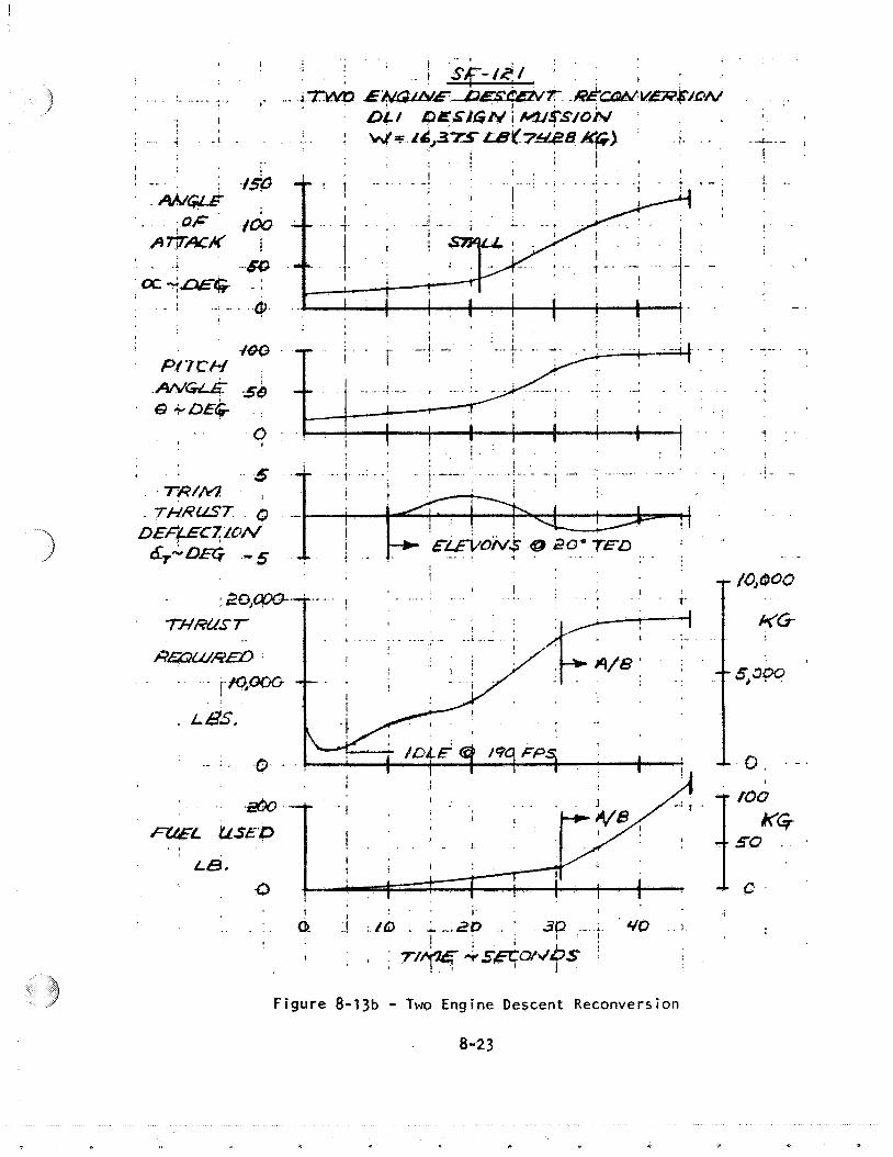
Figure 8-13b - Two Engine Descent Reconversion
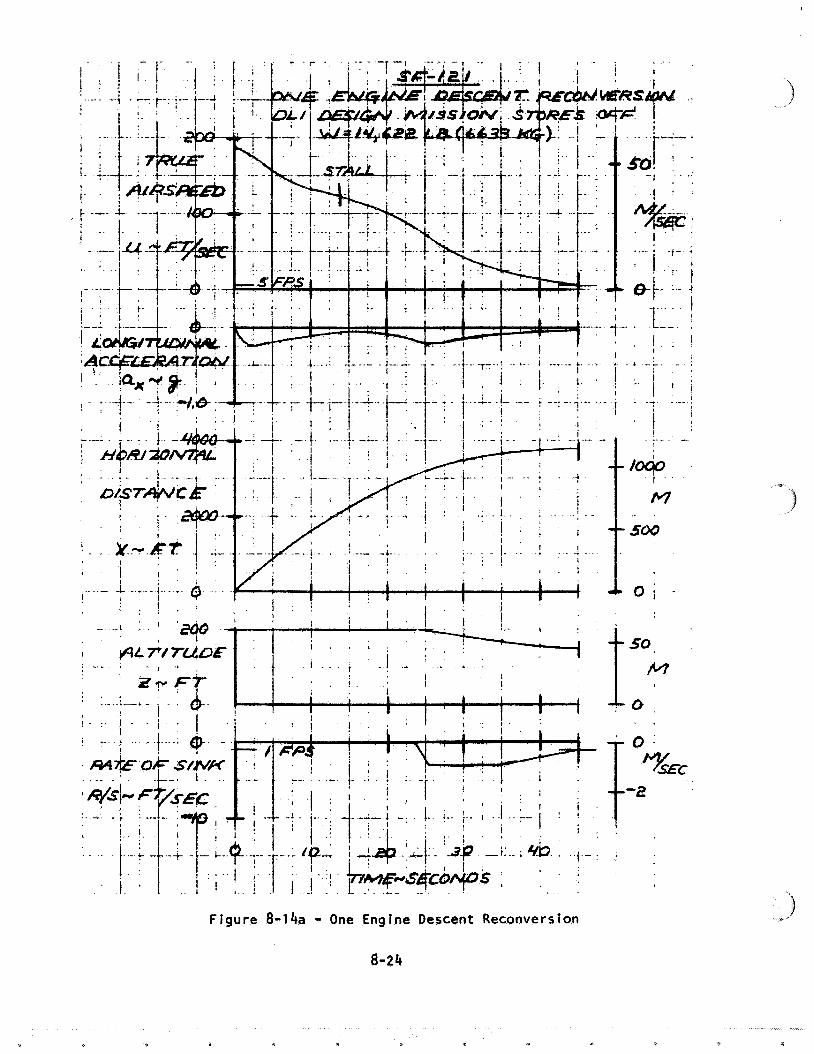
Figure 8-14a - One Engine Descent Reconversion 8-24
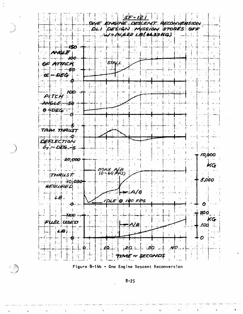
Figure 8-14b - One Engine Descent Reconversion 8-25

consumption decreased as expected when t rans i t i o n s were performed rap i d l y.
However, f u e l f low was e s s e n t i a l l y the same whether t r a n s i t i o n was descending
o r l e v e l . V e r t i c a l d is tance i n t r a n s i t i o n was a l so decreased w i t h the h igher
maxi mum p i t ch angle because o f increased t h r u s t requi red f o r braking.
Opera t iona l ly , a descending t r a n s i t i o n w i t h a maximum 95 degree p i t c h angle
appears pre ferab le because o f the smal l e r t h r u s t excurs.ions. Descent t o
land ing would be necessary a f t e r a l eve l dece lera t ion w i t h a consequent i n -
crease i n f u e l requ i red f o r landing.
A s tab le a i r c r a f t (+3 percent vs. bas i c -9.5 percent s t a t i c
margin) was a l s o eval uted. Several s i g n i f i c a n t d i f f e rences were noted
i n the t r a n s i t i o n t ime h i s t o r i e s . Reconversion was more r a p i d f o r the
s t a b l e a i r c r a f t desp i te a h igher i n i t i a l speed. L i f t , drag and moment
c h a r a c t e r i s t i c s are shown i n Figures 5-1 t h r u 5-3. These ind i ca te a lower CL
f o r 1.3 V S p A , lower CLHAX, and a considerable increase i n p i t c h i n g moment past
maximum l i f t . Decelerat ion t ime t o maximum 1 i f t was less f o r the s t a b l e
a i r c r a f t due t o the smal ler angle o f a t tack range t o be covered and the h igher
p i t c h r a t e requi red t o achieve n e a r - i d l e t h r u s t . Consequently, h igh post-
s t a l l drag was reached qu icker and a t a h igher speed. Therefore, the post -
s t a l l decelerat ion/descent was more r a p i d f o r the s t a b l e a i r c r a f t . T r im
t h r u s t d e f l e c t ion requi red exceeded the 15 degrees maximum throw avai l ab le .
This resul t i s p red i cated upon accurate assessment o f pos t - s t a l 1 aerodynamics
f o r the SF-121. Wind tunnel t e s t r e s u l t s a re c r i t i c a l t o assure acceptable
p i t c h i n g moments i n the p o s t - s t a l l regime, p a r t i c u l a r l y i f s tab le o r near-
s t ab le con f igu ra t i ons are des i red.
Using degraded maximum l i f t t o reduce t r a n s i t i o n t ime and d i s -
tance i s poss ib le w i t h both the unstab le and s t a b l e a i r c r a f t . The s i g n i f i -
cant f a c t o r s a r e b u f f e t i n t e n s i t y a t the h igher s t a l l speed and t h r u s t vec tor
p i t c h c o n t r o l requ i red both pre- and p o s t - s t a l l . The quest ion o f how.much
maximum l i f t i s a c t u a l l y des i rab le warrants f u r t h e r study. The wing and
canard v a r i a b l e camber schedules were opt imized f o r c r u i s e and maximum sus-
ta ined load fac to r . - The adapt ive f l y -by-wi re c o n t r o l system could e a s i l y be
programmed t o t a i l o r t he t r a n s i t i o n aerodynamics.
Sing le engine reconversions revealed several c o n t r o l power
1 i m i t a t i o n s (see F igu re 8-14) . Maximum p i t c h angle was l i n i t e d by t h r u s t
ava i 1 ab le f o r dece le ra t i on and/or descent. The min i mum excess T/W (see Table
8-3) c l e a r l y l e f t no margin f o r a t t i t u d e o r he igh t c o n t r o l . The SF-121 was
s i zed a t 1.03 T/W f o r hover which was found t o be inadequate. Discussions i n
Sect ions 8.3.3 and 8.3.4 i n d i c a t e t h a t a minimum 1.086 T/W i s necessary t o
meet MIL-F-83300 Level 2 hover f l y i n g qua1 i t i e s requi rernents. Carefu l assess-
ment o f m i d - t r a n s i t i o n c o n t r o l requirements w i l l a l s o be e s s e n t i a l . Fuel
consumption i n t r a n s i t i o n i s h igher because A/B 1 i g h t - o f f occurs much e a r l i e r .
I n summary:
o Two-engine reconversions appear t o be r e l a t i v e l y problem f r e e
o High angle o f a t t a c k aerodynamics cou ld be c r i t i c a l , e s p e c i a l l y
i f there are l a rge p i t c h i n g moment excursions
o Automatic f l i g h t pa th and t h r o t t l e c o n t r o l may be des i rab le ,
a l though p i l o t c o n t r o l l e d reconversions were performed w e l l
on the X-13
o A v a r i e t y o f f l i g h t pa th op t ions and l and ing c o n f i g u r a t i o n
aerodynamics may be needed t o min i m i ze b u f f e t i n reconversion
o Reconversion f u e l usage leaves ample reserve f o r f i n a l docking
o Ample excess T/W i s a v a i l a b l e f o r he igh t and a t t i t u d e con t ro l
f o r a normal two-eng i ne reconvers ion
o Single-engine T/W margins and f l i g h t paths w i l l have t o be
es tab l i shed very c a r e f u l l y ; T/W = 1.03 i s u n r e a l i s t i c a l l y low
8.3.2 Takeof f Conversion
Conversion performance ( t r a n s i t i o n from hover t o convent ional
f l i g h t ) was evaluated a t the design miss ion t a k e o f f weight o f 23,375 pounds.
Level f l i g h t was achieved w i t h i n 10.4 seconds a f t e r reaching f u l l t h r o t t l e .
I n i t i a l c l imb speed was reached i n 17.0 seconds w i t h l ess than 400 pounds
f u e l burned. The minimum excess t h r u s t t o weight was 1.29 a t hover which pro-
v ided s u b s t a n t i a l margin f o r he igh t and a t t i t u d e c o n t r o l . The f l i g h t path
was se lec ted t o minimize p i l o t exposure t o non-recoverable engine f a i l u r e
(See F igure 8-14).
Conversions were s imulated us ing a mod i f i ed vers ion o f the computer
r o u t i n e used t o c a l c u l a t e reconversions. The program was modi f ied t o main ta in
l e v e l f l i g h t once i t was reached. Conversion began w i t h a p i t chover t o angle
o f a t tack f o r 0.9 CL.,~ Angle o f a t t a c k was h e l d constant u n t i 1 r a t e o f
c l imb peaked and then decreased t o i n t e r c e p t l e v e l f l i g h t . Maximum t h r u s t was
used u n t i 1 the end o f conversion. Fuel use ca l cu la ted f o r t h i s conversion
was conservat i ve because a p i l o t would normal l y reduce t h r u s t t o in termediate
power a t a lower l e v e l f l i g h t speed. The t ime h i s t o r y s.hown i n F igure 8-15
shows very smooth v a r i a t i o n s o f a l l var iab les . Th is p r o f i l e should c reate
minimal p i l o t workload w i t h increas ing b u f f e t due t o a i rspeed used t o cue the
p i l o t t o pushover. An automat ica l ly c o n t r o l l e d conversion i s poss ib le w i t h
p i t c h angle and c l imb r a t e sensing, bu t considerable development w i l l be
needed t o assure c o m p a t i b i l i t y over a wide range o f ope ra t i ng cond i t ions .
I n summary, the outbound t r a n s i t i o n maneuver does not appear t o
present any ser ious problems, but the d e t a i l s warrant f u r t h e r study t o develop
p i l o t procedures t o minimize t ime and fue l w i thout approaching the s t a l l region.
8.3.3 A t t i t u d e Control System
F ina l determinat ion o f VATOL con t ro l power requirements w i l l rn
necess i ta te manned s imu la t i on i nc lud ing e f f e c t s o f s h i p motion. For t h i s
study, maximum a v a i l a b l e c o n t r o l power was evaluated against MIL F-83300 and
1 AGARD 577 c r i t e r i a rev ised t o r e f l e c t VTOL fl i g h t t e s t experience and VATOL
opera t ing c h a r a c t e r i s t i c s . Maximum a v a i l a b l e c o n t r o l power was determined
f o r two types o f a t t i t u d e c o n t r o l systems. The bas ic SF-121 system comprises
t h r u s t vec to r ing con t ro l (TVC) f o r p i t c h and yaw and reac t ion j e t r o l l
c o n t r o l . An a l t e r n a t e system using reac t ion j e t con t ro l about a l l axes was
compared t o the bas ic system. Results showed the b a s i c system t o be d i s -
t i n c t l y super io r . As a r e s u l t o f these s tud ies , rev ised design t h r u s t t o
weight c r i t e r i a were developed. These increase minimum t h r u s t t o weight
used t o design the SF-121. An apparent problem uncovered was ser ious
d i r e c t i o n a l i n s t a b i l i t y a t above 26 degrees angle o f a t tack . Conf igura t ion
development wind tunnel t e s t s t o reduce o r e l i m i n a t e the i ns tab i 1 i t y are
c l e a r l y ind ica ted.
The two types o f a t t i t u d e c o n t r o l systems analyzed are i l l u s t r a t e d
i n F igure 8-16. The bas ic SF-121 system uses engine nozzles gimbal led i n
p i t c h and yaw, w i t h compressor b leed j e t s a t the w ing t ips f o r r o l l con t ro l .
For s i n g l e engine t r a n s i t i o n , the opera t i ng nozzle i s b iased through the
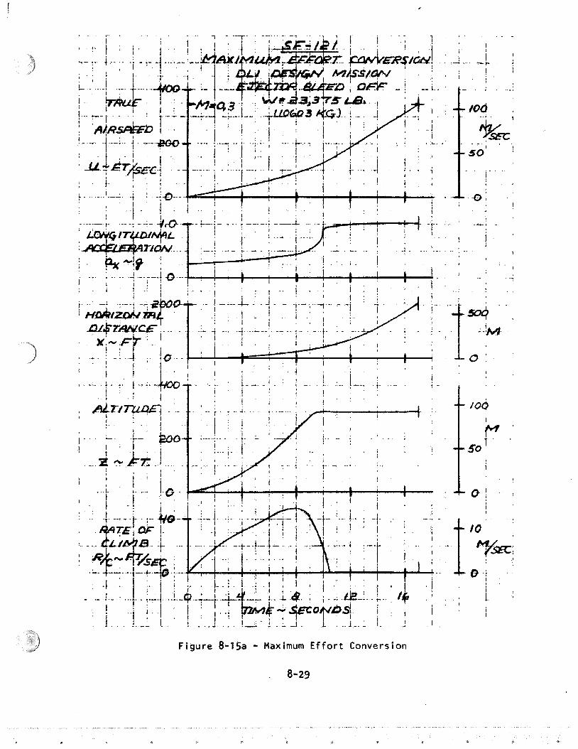
Figure 8-15a - Maximum E f f o r t Conversion
8-29
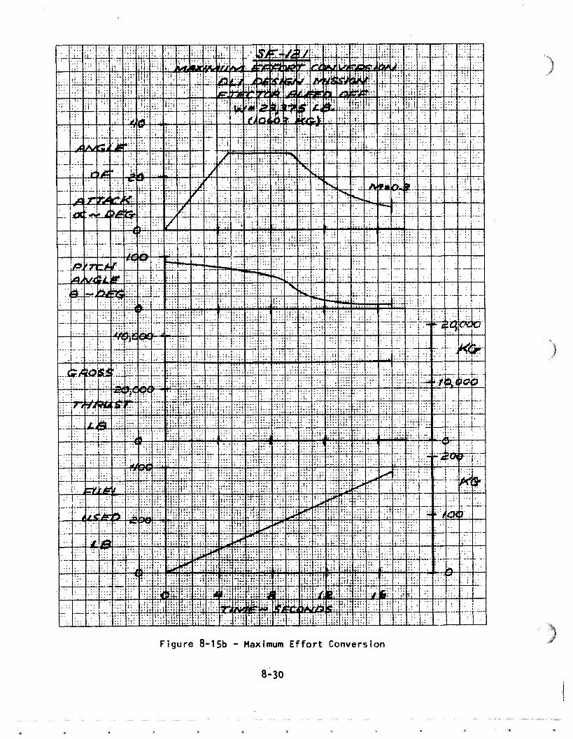
Figure 8-15b - Maximum E f f o r t Conversion
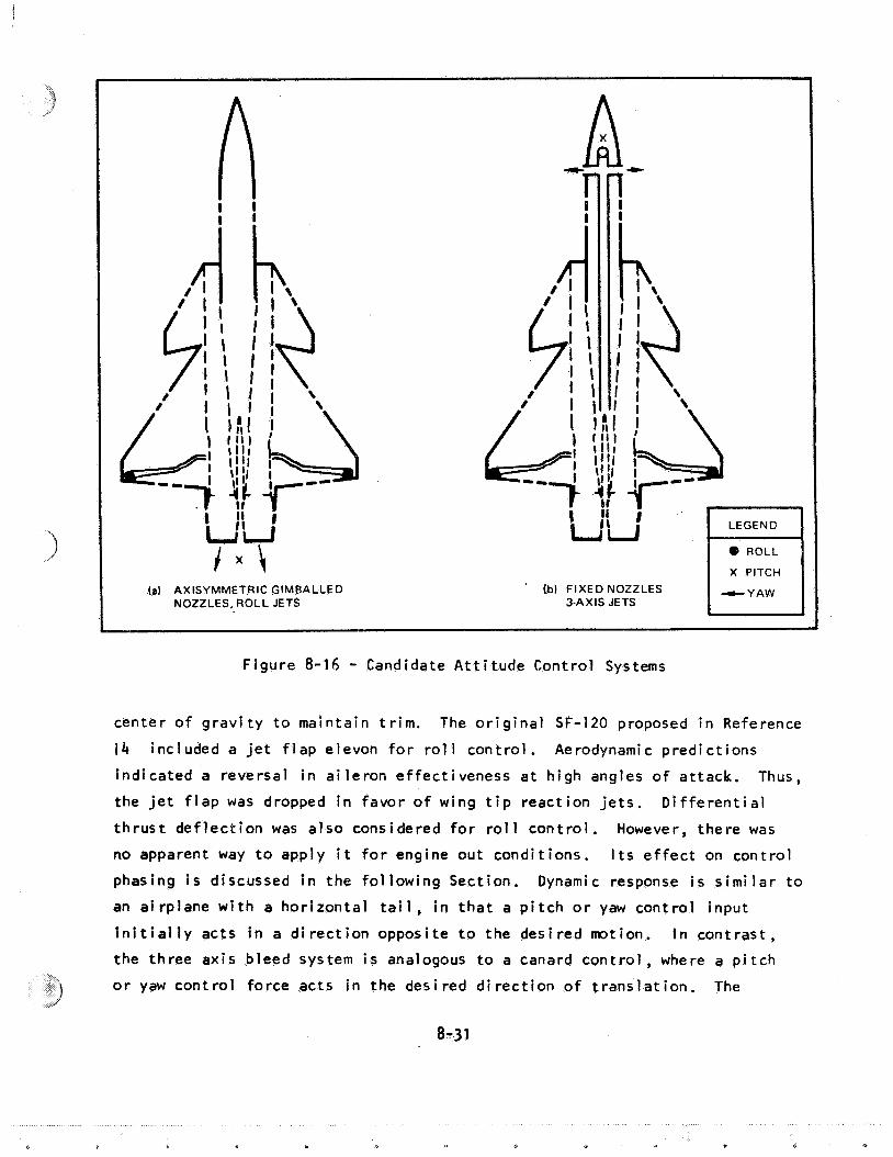
(a) AXISYMMETRIC GIMBALLED (b) F IXED NOZZLES NOZZLES, ROLL JETS 3-AXIS JETS
Figure 8-16 - Candidate A t t i t u d e Control Systems
center o f g rav i t y t o maintain t r i m . The o r i g i n a l SF-120 proposed i n Reference
14 included a j e t f l a p elevon f o r r o l l cont ro l . Aerodynamic pred ic t ions
indicated a reversal i n a i le ron ef fect iveness a t h igh angles o f at tack. Thus,
the j e t f l a p was dropped i n favor o f wing t i p react ion j e t s . D i f f e r e n t i a l
t h rus t def lec t ion was a lso considered fo r r o l l con t ro l . However, there was
no apparent way t o apply i t f o r engine out condi t ions. I t s e f f e c t on control
phasing i s discussed i n the fo l low ing Section. Dynamic response i s s i m i l a r t o
an a i rp lane w i t h a hor izonta l t a i 1 , i n t h a t a p i t c h o r yaw cont ro l input
i n i t i a l l y acts i n a d i r ec t i on opposite t o the desired motion. I n cont rast ,
the three axis b leed system i s analogous t o a canard con t ro l , where a p i t c h
o r yaw con t ro l force acts i n the desired d i r ec t i on o f t rans la t ion . The
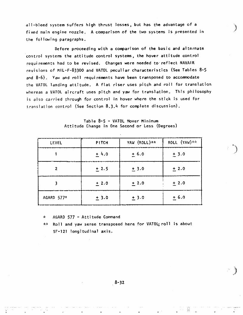
a l l - b l eed system su f fe rs h igh th rus t losses, but has the advantage o f a
f i xed main engine nozzle. A comparison o f the two systems i s presented i n
the f o l lowing paragraphs.
Before proceeding w i t h a comparison o f the bas ic and a l te rna te
cont ro l systems the a t t i t u d e cont ro l systems, the hover a t t i t u d e cont ro l
requi rements had t o be rev i sed. Changes were needed t o . r e f l e c t NAVAI R
rev is ions o f M I L - F - ~ ~ ~ O O and VATOL pecul i a r charac te r i s t i cs (See Tables 8-5
and 8-6) . Yaw and r o l l requi rements have been t ransposed t o accommodate
the VATOL landing a t t i t u d e . A f l a t r i s e r uses p i t c h and r o l l f o r t rans la t ion
whereas a VATOL a i r c r a f t uses p i t c h and yaw f o r t rans la t ion . This phi losophy
i s a lso ca r r ied through fo r cont ro l i n hover where the s t i c k i s used f o r
t r ans la t i on cont ro l (see Section 8.3.4 f o r complete discussion).
Table 8-5 - VATOL Hover Minimum A t t i t u d e Change i n One Second o r Less ( ~ e ~ r e e s )
AGARD 577 - A t t i t u d e Command
** Ro l l and yaw sense transposed here f o r VAT0L;roll i s about
SF-121 long i tud ina l axis.
ROLL (YAW)**
+ 3.0 -
+ 2.0 -
LEVEL
1
2
I
PITCH
+ 4.0 - + 2.5 -
m
3
AGARD 577" L
YAW (ROLL) **
+ 6.0 -
+ 3.0 -
+ 2.0 -
- + 3 .0
+ 2.0 I - 4 + 2.0 - I
+ - 3.0 - + 6.0
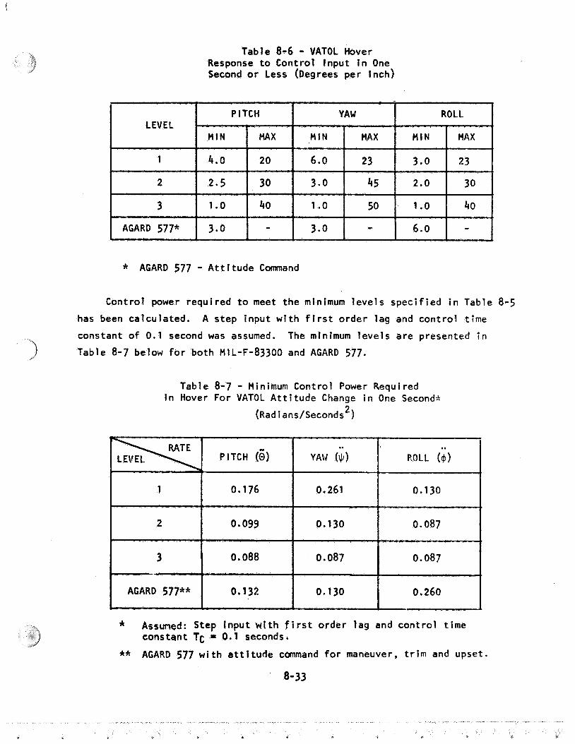
Table 8-6 - VATOL Hover Response t o Control Input i n One Second o r Less (Degrees per inch)
* AGARD 577 - A t t i t u d e Command
Control power required t o meet the minimum leve ls spec i f i ed i n Table 8-5
has been calculated. A step input w i t h f i r s t order lag and con t ro l time
constant o f 0.1 second was assumed. The minimum leve ls are presented i n
Table 8-7 below f o r both MIL-F-83300 and AGARD 577.
Table 8-7 - Hinimum Control Power Required I n Hover For VATOL A t t i t ude Change i n One Secondft
* Assumed: Step Input w i t h f i r s t order lag and cont ro l t ime constent TC = 0.1 seconds.
3 .
AGAR0 577"" I
** AGARD 577 w i t h a t t i t u d e command f o r maneuver, t r i m and upset.
0.088
0.132
0.087
0.130
0.087
0.260
The fo l low ing discussions pe r t a i n on ly t o con t ro l i n hover. Control i n
t r a n s i t i o n i s reviewed i n Section 8 . 3 . 4 . Maximum p i t ch , yaw, and r o l l con t ro l
ava i lab le i s compared t o required con t ro l l eve ls f o r the basic and a l t e rna te
systems respect ively. The maximum VTOG\J and DL1 VLGW loadings were selected
t o i l l u s t r a t e the extremes o f hover con t ro l ava i lab le w i t h t w o engines opera-
t ing. Single engine v e r t i c a l landing was chosen t o eva!uate the v a l i d i t y
o f the SF-121 design t h rus t t o weight. Assumptions used f o r ca lcu la t ion o f
maximum ava i lab le con t ro l were:
A l l cont ro ls a re s ing le ax is (no cross coupl ing)
Control inputs are l i m i t e d t o values which maintain T/\J 1.0
Reaction j e t cont ro ls use demand bleed.
P i t ch and yaw con t ro l are l i m i t e d by t h rus t vector de f l ec t i on o f
15 degrees only.
Ro l l con t ro l i s 1 i m i ted by ava i lab le excess t h rus t t o weight. or s ing le engine v e r t i c a l landing add i t i ona l r o l l cont ro l can be
obtained by a1 lowing t rans ien t overtemperature. )
I n e r t i a and weights are f o r the SF-121 po in t design. A summary o f
weights and i ne r t i as f o r conf igurat ions evaluated i n t h i s sect ion
i s presented as Table 8-8.
Propulsion charac te r i s t i cs are f o r the 1.131 scale engine o f the
SF-121 po in t design.
Reaction j e t t h rus t f o r a l te rna te con t ro l system p i t c h and yaw
thrusters i s twice tha t f o r each r o l l react ion j e t
Thrust ava i lab le f o r a l l t r ans i t i ons i s w i t h e jec to r bleed o f f .
Maximum hover con t ro l powers ava i lab le about p i t ch , yaw and r o l l axes,
f o r both con t ro l systems are presented i n Figure 8-17 and 8-18 and Table 8-9.
For comparison purposes, maximum con t ro l power required per !Il l-F-83300 has
been postulated. This was done by ext rapo la t ing con t ro l power required per
inch o f con t ro l motion t o t yp i ca l maximum s t i c k and pedal throws. The throws
selected f o r maximum con t ro l input are:
Control
Longi tudinal ( s t i c k )
Latera l ( s t i c k )
D i rec t iona l (Pedal)
Throw - + 6.0 inches - + 2.5 inches - + 2.5 inches -
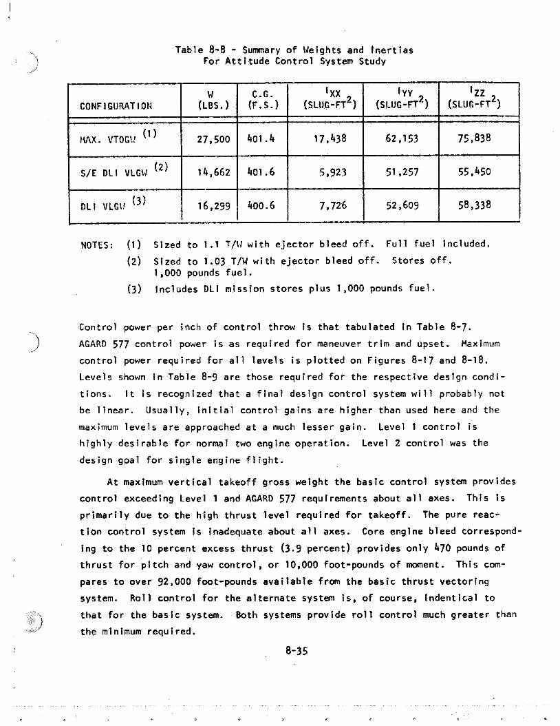
Table 8-8 - Summary o f Weights and I ne r t i as For A t t i t u d e Control System Study
CONFIGURATION
NOTES: (1) Sized t o 1.1 ?/ \ I w i t h e j ec to r bleed o f f . F u l l f ue l included.
(2) Sized t o 1.03 T/W w i t h e j ec to r bleed o f f . Stores o f f . 1,000 pounds fue l .
(3) Includes DL1 mission stores plus 1,000 pounds f ue l .
Control power per inch o f con t ro l throw i s tha t tabulated i n Table 8-7.
AGARD 577 cont ro l power i s as required fo r maneuver t r i m and upset. Maximum
con t ro l power required f o r a l l leve ls i s p l o t t ed on Figures 8-17 and 8-18.
Levels shown i n Table 8-9 are those required f o r the respective design condi-
t ions. It i s recognized t ha t a f i n a l design con t ro l system w i l l probably not
be l i nea r . Usual ly, i n i t i a l cont ro l gains are higher than used here and the
maximum leve ls a re approached a t a much lesser gain. Level 1 cont ro l i s
h i gh l y des i rab le f o r normal two engine operation. Level 2 con t ro l was the
design goal f o r s ing le engine f l i g h t .
At maximum v e r t i c a l takeof f gross weight the basic cont ro l system provides
con t ro l exceeding Level 1 and AGARD 577 requlrements about a l l axes. This i s
p r ima r i l y due t o the h igh th rus t l eve l required f o r takeoff . The pure reac-
t i o n con t ro l system i s inadequate about a l l axes. Core engine bleed correspond-
ing t o the 10 percent excess th rus t (3.9 percent) provides on ly 470 pounds o f
t h rus t f o r p i t c h and yaw con t ro l , o r 10,000 foot-pounds o f moment. This com-
pares t o over 92,000 foot-pounds ava i lab le from the basic th rus t vector ing
system. Ro l l con t ro l f o r the a l t e rna te system is , o f course, indent ica l t o
t ha t f o r the basic system. Both systems provide r o l l con t ro l much greater than
the minimum required.
8-35
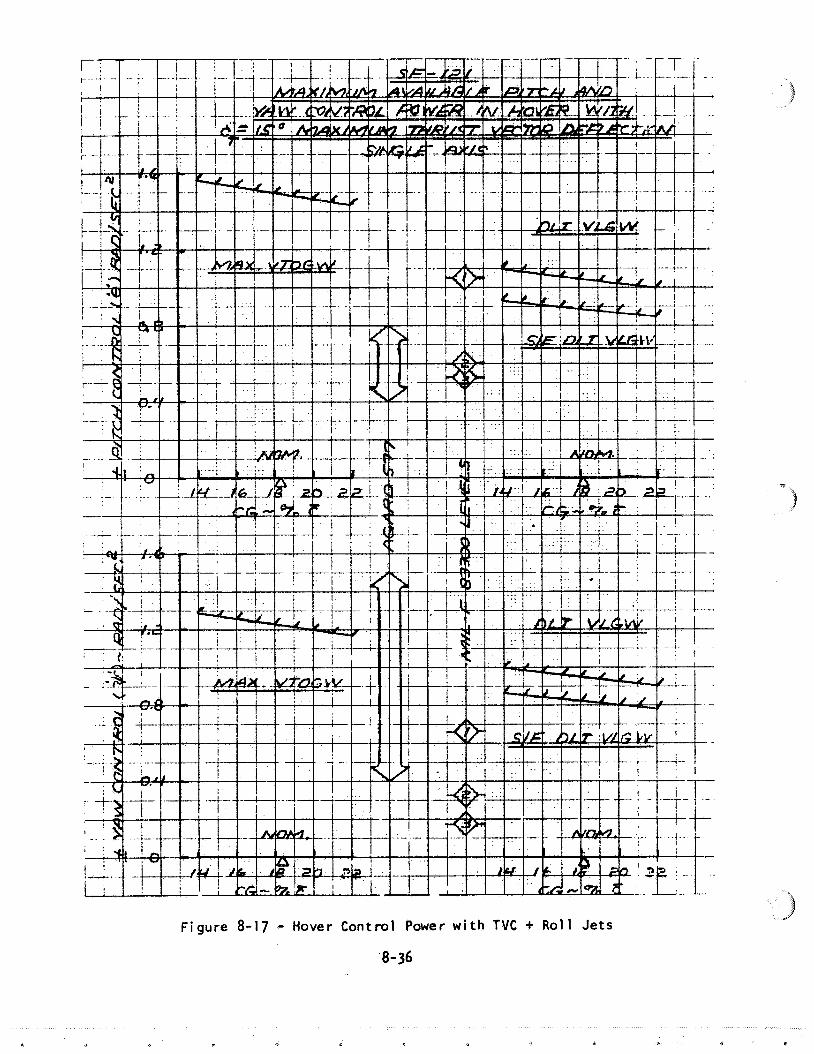
Figure 8-1 7 - Hover Control Power with TVC + Roll Jets
8-36
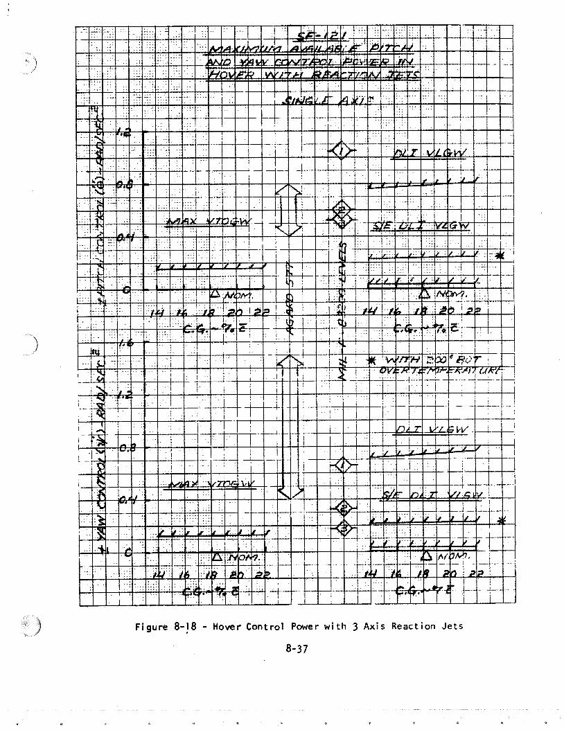
Figure 8-18 - Hover Control Power with 3 Axis Reaction Jets
8-37
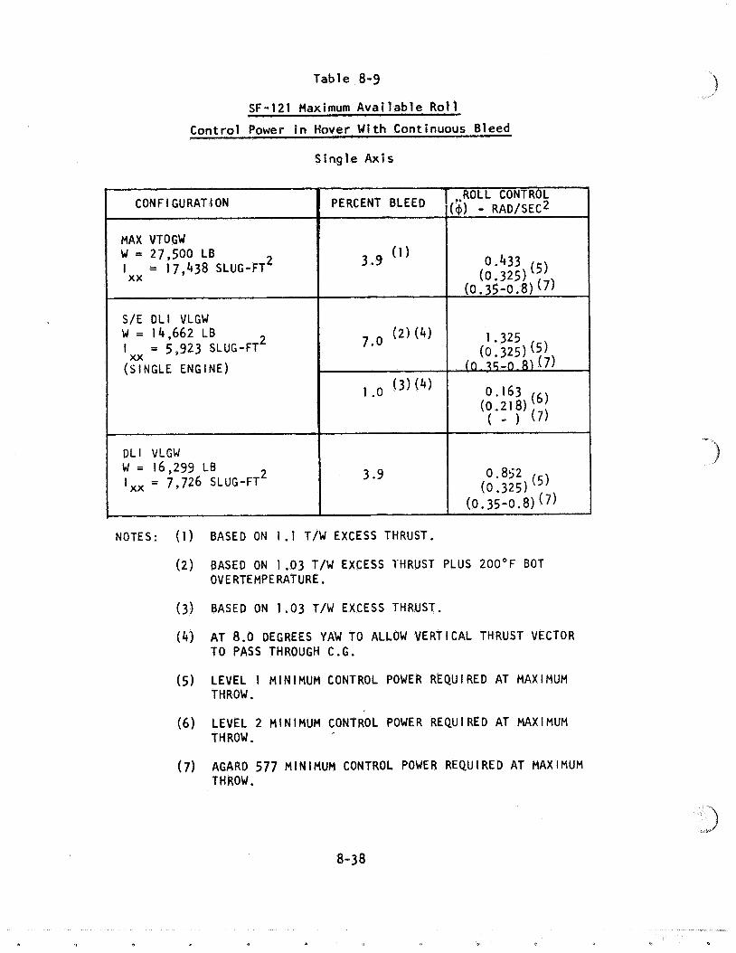
Table 8-9
SF-121 Maximum Ava i l ab le R o l l
Contro l Power i n Hover With Continuous Bleed
S ing le Ax is
NOTES: ( 1 ) BASED ON 1 . I T/W EXCESS THRUST*
r CONFl GURATION
MAX VTOGW W = 27,500 LB I = 17,438 SLUG-FT
2 x x
S/E DL1 VLGW W = 14,662 LB 2 I = 5,923 SLUG-FT
XX (SINGLE ENGINE)
DL1 VLGW W = 16,299 LB 2 I ,, = 7,726 SLUG-FT
(2) BASED ON 1 .03 T/W EXCESS 1'HRUST PLUS 200°F BOT OVERTEMPERATURE.
(3) BASED ON 1.03 T/W EXCESS THRUST.
PERCENT BLEED
3.9 ( ' I
7.0 (2) (4)
1 .o (3) (4)
3.9
(4) AT 8.0 DEGREES YAW TO ALLOW VERTICAL THRUST VECTOR TO PASS THROUGH C .G.
- ROLL CONTROL - R A D / S E C ~
0.433 (s) (0.325)
(0.35-0.8) (7)
1 .325
0-163 (6) (0.21 8) ( - ) (7)
0.852 (0.325) (*)
(0.35-0.8) (7)
(5) LEVEL 1 M l N IMUM CONTROL POWER REQUl RED AT MAXIMUM THROW.
( 6 ) LEVEL 2 MINIMUM CONTROL POWER REQUl RED AT MAXI MUM THROW.
(7 ) AGARD 577 M l N l MUM CONTROL POWER REQU l RED AT MAX l MUM THROW.
At the normal two engine landing condition the basic system provides
1 adequate control about all axes. The alternate system is satisfactory for
roll and yaw control. It does not meet the postulated Level 1 requirement
for pitch control, but is adequate for AGARD 577. It should be noted that
15 percent bleed (2,000 pounds reaction jet thrust) was assumed for the a1 1 -
reaction jet pitch and yaw control. Bleed for roll control was set at 3.9
percent for comparison with the takeoff case.
For single engine landing, the control requirements were relaxed to
Level 2. The basic control system provides satisfactory control power in
pitch and yaw, but is deficient in roll with only 3 percent thrust margin available for bleed. If a transient 200°F BOT overtemperature is allowed
more than ample roll control is available. In the absence of an overtempera-
ture allowance, an increased engine size would be needed. Subsequent discussion
reviews the impact of no overtemperature allowance on aircraft sizing. The
three axis reaction jet control system performance with the 3 percent thrust
excess is completely unsatisfactory. \/ith the overtemperature allowance, roll
performance again exceeds Level 1 assumed requirements. The basic system
again is clearly superior but an attractive sizing factor is apparent if
transient overtemperature is allowed for emergency operations.
Capability of the SF-121 basic control system to meet MIL-F-83300 and
AGARD 577 attitude control response requirements is illustrated in Table 8-10
below. tfinimum requirements are met in all cases except for single engine DL1
vertical landing roll control response for AGARD 577 requirements. As shown,
a 200'~ BOT transient overtemperature a1 lows a substant i a1 improvement. Higher
design T/W would also yield acceptable performance. The responses in this
table represent a likely minimum design capability. In practice, output to
input gains are normally high at low control input and decrease as more control
is demanded. Responses for the alternate all reaction jet system are not
shown because of the deficiencies discussed previously.
Aircraft sizing studies discussed in Section 8.1 revealed that single
engine vertical landing thrust to weight was the principal engine sizing factor.
Because of the deficiencies noted for single engine landing roll control the
T/W = 1.03 sizing criterion appears inadequate. MIL-F-83300 paragraph
3.2.3.1 requires: "Simultaneous application of pitch, roll and yaw controls
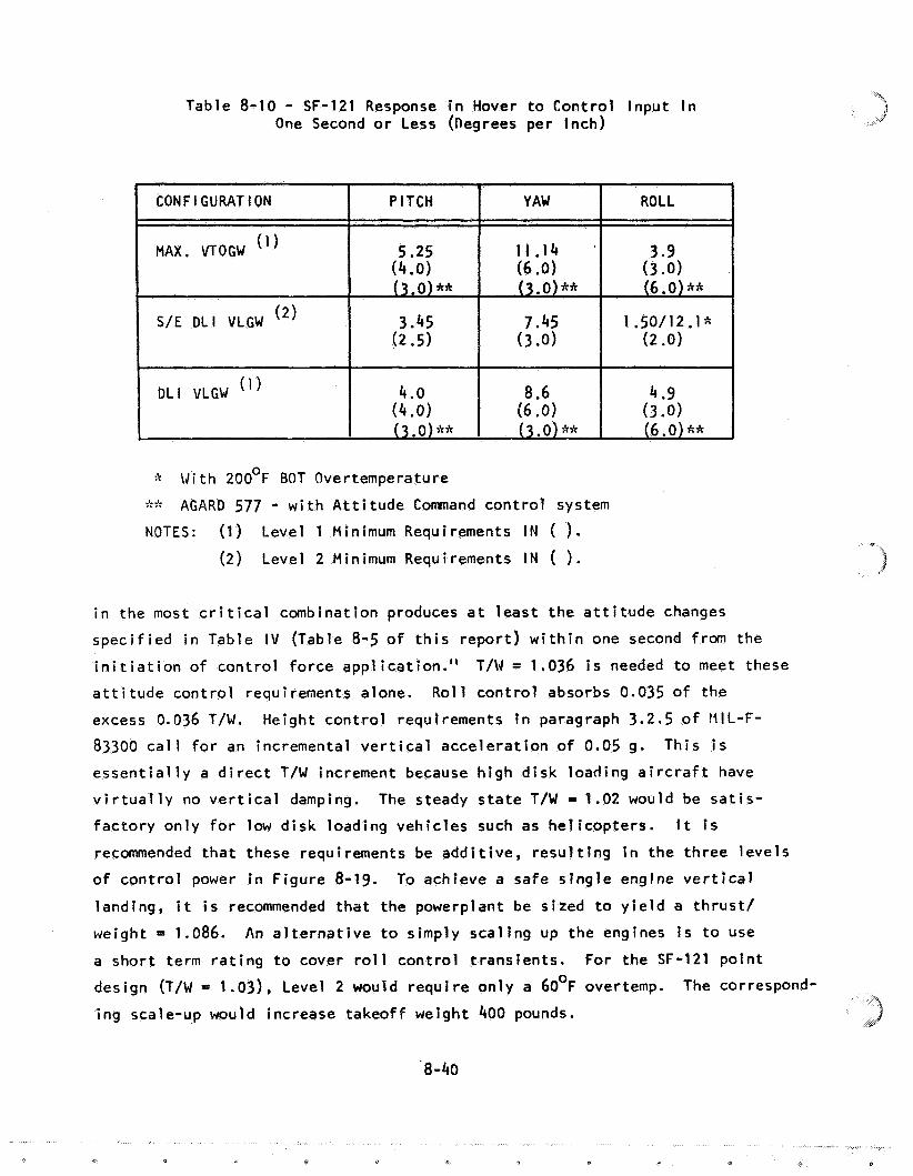
Table 8-10 - SF-121 Response i n Hover t o Control Input I n One Second o r Less (negrees per lnch)
\ J i t h 200'~ BOT Overtempera tu re
,. #. "" AGAR0 577 - w i t h A t t i t u d e Command cont ro l system
NOTES: ( 1 ) Level 1 Minimum Requirements I N ( ) .
(2) Level 2 Minimum Requirements IN ( ).
i n the most c r i t i c a l combination produces a t least the a t t i t u d e changes
spec i f ied i n Table 1V (Table 8-5 o f t h i s report) w i t h i n one second from the
i n i t i a t i o n o f cont ro l force appl icat ion." T/\J = 1.036 i s needed t o meet these
a t t i t u d e cont ro l requirements alone. Ro l l cont ro l absorbs 0.035 o f the
excess 0.036 T/W. Height con t ro l requirements I n paragraph 3.2.5 o f MIL-F-
83300 c a l l f o r an incremental v e r t i c a l acce lera t ion of 0.05 g. This i s
essen t i a l l y a d i r e c t TIW increment because high d isk loading a i r c r a f t have
v i r t u a l l y no v e r t i c a l damping. The steady s ta te T/W = 1.02 would be sa t i s -
factory only fo r low d i sk loading vehic les such as he l icopters . I t i s
recommended tha t these requirements be addi t ive , r esu l t i ng i n the three leve ls
of con t ro l power i n Figure 8-79. To achieve a safe s ing le engine v e r t i c a l
landing, i t i s recommended tha t the powerplant be sized t o y i e l d a th rus t /
weight = 1.086. An a l t e r n a t i v e t o simply sca l ing up the engines i s t o use
a short term r a t i n g t o cover r o l l cont ro l t ransients. For the SF-121 po in t
design (T/w = 1-03), Level 2 would requi r e on1 y a 6 0 O ~ overtemp. The correspond-
ing scale-up would increase takeoff weight 400 pounds.
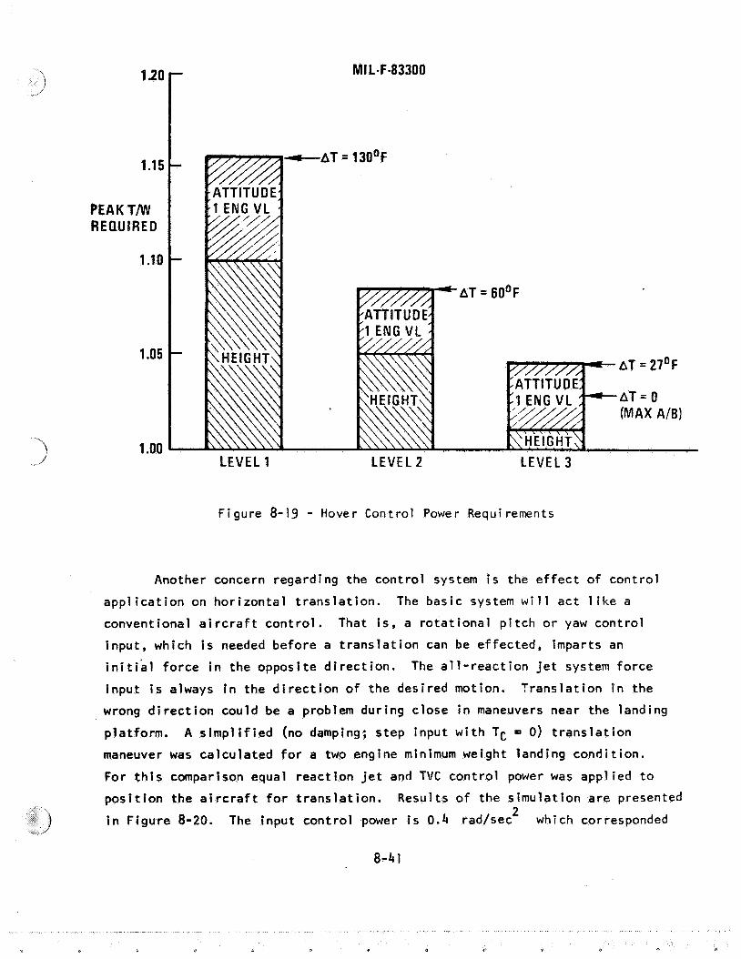
PEAK T/W REQUIRED
LEVEL 1 LEVEL 2 LEVEL 3
Figure 8-19 - Hover Control Power Requi rements
Another concern regarding the control system is the effect of control
application on horizontal translation. The basic system will act like a
conventional aircraft control. That is, a rotational pitch or yaw control
input, which is needed before a translation can be effected, imparts an
initial force in the opposite direction. The all-reaction jet system force
input is always in the direction of the desired motion. Translation in the
wrong direction could be a problem during close in maneuvers near the landing
platform. A simplified (no damping; step input with TC = 0) translation maneuver was calculated for a two engine minimum weight landing condition.
For this comparison equal reaction jet and TVC control power was applied to
position the aircraft for translation. Results of the simulatlon are presented 2
in Figure 8-20. The input control power is 0.4 rad/sec which corresponded
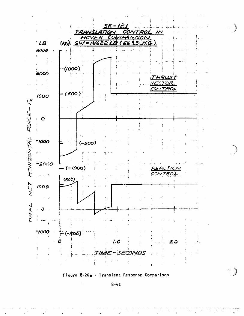
Figure 8-20a - Trans i ent Response Comparison
8-42
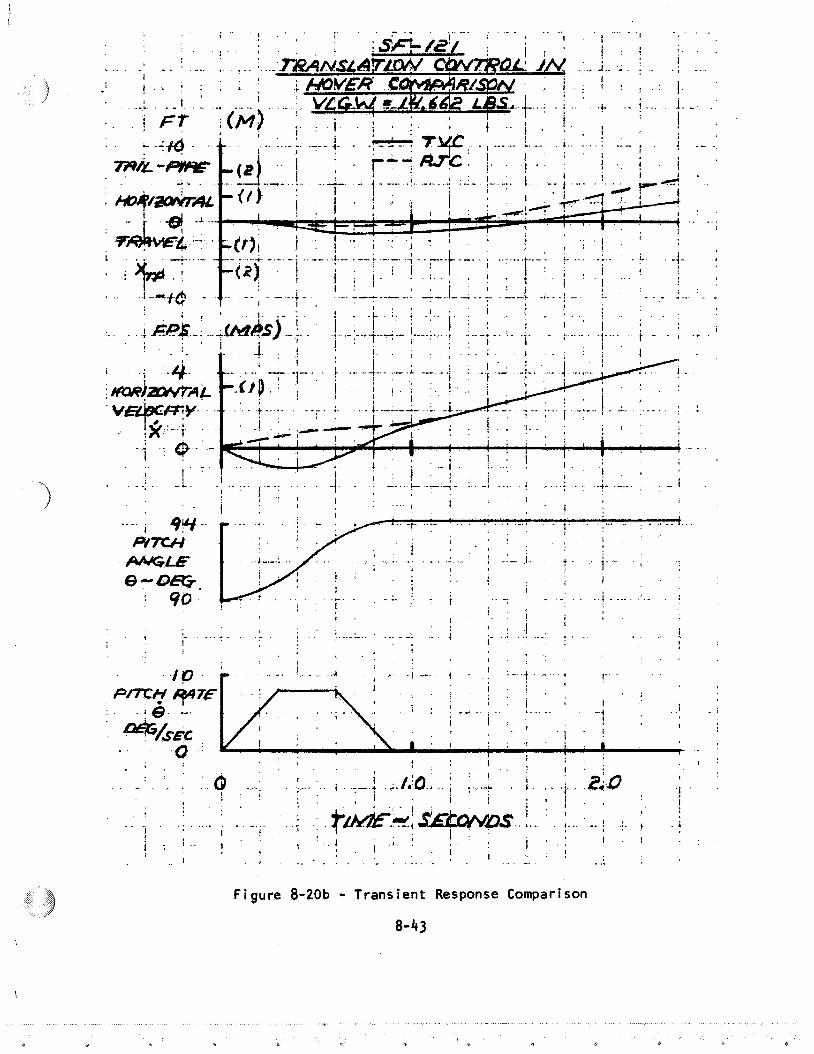
Figure 8-20b - Transient Response Comparison
t o 1,000 pounds o f react ion j e t force and 6.5 degree t h rus t de f l ec t ion.
Reaction j e t s are superior as a t r ans la t i on cont ro l . For a given input , more
than twice the distance was t raveled w i t h i n 3.0 seconds w i t h no adverse motion
versus cont ro l from the basic system. Adverse t r a n s i t i o n a t the center o f
g r a v i t y i s approximately 0.5 feet . The bottom edge o f the t a i l p i p e , however,
moves as much as 1.5 f ee t adversely. This i s approximately one- th i rd o f the
t a i l clearance ava i lab le w i t h the gear touching the landing platform.
Capab i l i t y t o t r i m the a i r c r a f t i n v e r t i c a l a t t i t u d e i n a 35 knot
crosswind i s ample. I f we assume a s ide fo rce drag c o e f f l c i e n t o f 1.0 the
calculated s ide fo rce i s 870 pounds. The cen t ro id o f area o r assumed center
o f pressure i s a t the center o f g rav i t y . T i l t required t o t r i m ou t the cross-
wind i s :
- 1 $ = s i n 870) = 3.06 degrees. (16,299
For the s ing le engine v e r t i c a l landing the required t i l t would be increased
t o 3 . 4 degrees. Confirmation o f the aerodynamic estimates made f o r t h i s
ca l cu la t i on w i l l have t o come from wind tunnel tes ts .
8.3.4 Reconversion Control Phasing
Reconversion ro l l /yaw cont ro l phasing which minimizes opposite
ax is coupl ing w i t h a i r c r a f t p i t c h a t t i t u d e has been evaluated. Schedules deter-
mined maintain the re la t ionsh ip o f p i l o t ' s conventional f l i g h t cont ro ls w i t h
the horizon through reconversion t o hover which should minimize p i l o t work-
load and t r a i n i n g time. The basic r o l l react ion j e t p lus yaw th rus t vector ing
and an a l l th rus t vector ing system have been studied. Phasings o f r o l l reac-
t i o n j e t t h rus t and d i f f e r e n t i a l th rus t de f l ec t i on w i t h yaw th rus t de f l ec t i on
have been determined f o r f u l l l a t e r a l s t i c k and rudder pedal inputs. Control
power required a t maximum con t ro l throw was set t o meet MIL-F-83300 require-
ments. Phasing o f the required con t ro l power from conventional t o v e r t i c a l
a l t i t u d e was made proport ional t o i n e r t i a s about the respect ive con t ro l axes.
Weights and i n e r t i a s used are f o r the SF-121 design VL condi t ion.
Results show tha t required t h rus t vector def lec t ions and r o l l reac t ion j e t
th rus t l eve ls are eas i l y a t ta inab le over the e n t i r e p i t c h range.
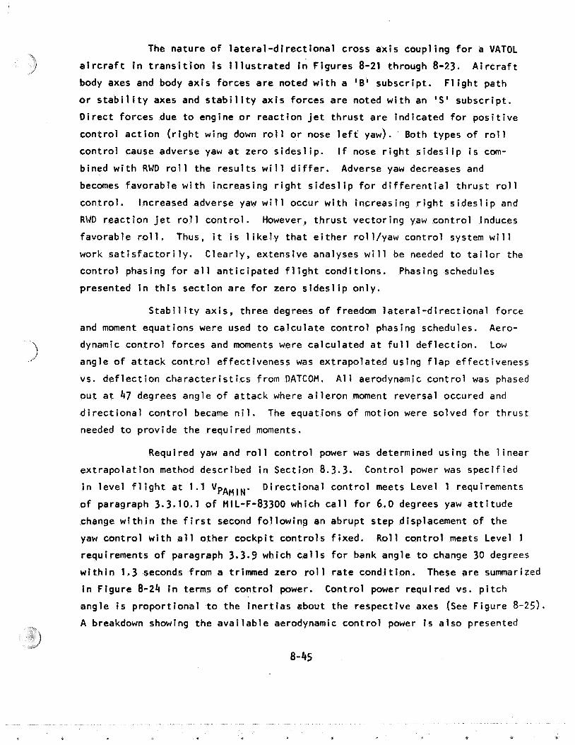
The nature of l a t e ra l - d i r ec t i ona l cross ax i s coupl ing f o r a VATOL
a i r c r a f t i n t r a n s i t i o n i s i l l u s t r a t e d i n Figures 8-21 through 8-23. A i r c r a f t
body axes and body ax is forces a re noted w i t h a ' B ' subscr ipt . F l i g h t path
o r s t a b i l i t y axes and s t a b i l i t y ax i s forces are noted w i t h an ' S ' subscr ipt .
D i r ec t forces due t o engine o r react ion j e t th rus t a re indicated f o r p o s i t i v e
con t ro l ac t i on ( r i g h t wing down r o l l o r nose l e f t ' yaw). ' Both types o f r o l l
con t ro l cause adverse yaw a t zero s i des l i p . I f nose r i g h t s i d e s l i p i s com-
bined w i t h RWD r o l l the resu l t s w i l l d i f f e r . Adverse yaw decreases and
becomes favorable w i t h increasing r i g h t s i d e s l i p f o r d i f f e r e n t i a l th rus t r o l l
cont ro l . Increased adverse yaw w i l l occur w i t h increasing r i g h t s i d e s l i p and
R\JD react ion j e t r o l l con t ro l . However, th rus t vector ing yaw con t ro l induces
favorable r o l l . Thus, i t i s l i k e l y tha t e i t h e r ro l l /yaw cont ro l system w i l l
work s a t i s f a c t o r i l y . C lear ly , extensive analyses w i l l be needed t o t a i l o r the
con t ro l phasing f o r a l l an t i c ipa ted f l i g h t condi t ions. Phasing schedules
presented i n t h i s sect ion a re f o r zero s i d e s l i p only.
S t a b i l i t y ax is , three degrees o f freedom l a te ra l - d i r ec t i ona l force
and moment equations were used t o ca lcu la te con t ro l phasing schedules. Aero-
dynamic con t ro l forces and moments were calculated a t f u l l de f lec t ion . Low
angle o f a t tack con t ro l ef fect iveness was extrapolated using f l a p ef fect iveness
vs. de f l ec t i on charac te r i s t i cs from DATCOM. A l l aerodynamic con t ro l was phased
out a t 47 degrees angle o f a t tack where a i le ron moment reversal occured and
d i r ec t i ona l con t ro l became n i l . The equations o f motion were solved f o r th rus t
needed t o provide the required moments.
Required yaw and r o l l con t ro l power was determined using the l i nea r
ex t rapo la t ion method described i n Section 8.3.3. Control power was spec i f ied
i n leve l f l i g h t a t 1.1 VpAHIN. D i rec t iona l con t ro l meets Level 1 requirements
o f paragraph 3.3.10.1 o f HlL-F-83300 which c a l l f o r 6.0 degrees yaw a t t i t u d e
change w i t h i n the f i r s t second fo l low ing an abrupt step displacement o f the
yaw con t ro l w i t h a l l other cockp i t con t ro ls f ixed. Ro l l con t ro l meets Level 1
requirements o f paragraph 3.3.9 which c a l l s f o r bank angle t o change 30 degrees
w i t h i n 1.3 seconds from a trimmed zero r o l l r a t e condi t ion. These are summarized
i n Figure 8-24 i n terms o f con t ro l power. Control power required vs. p i t c h
angle i s propor t iona l t o the i ne r t i as about the respect ive axes (see Figure 8-25).
A breakdown showing the ava i lab le aerodynamic con t ro l power i s a lso presented
8-45
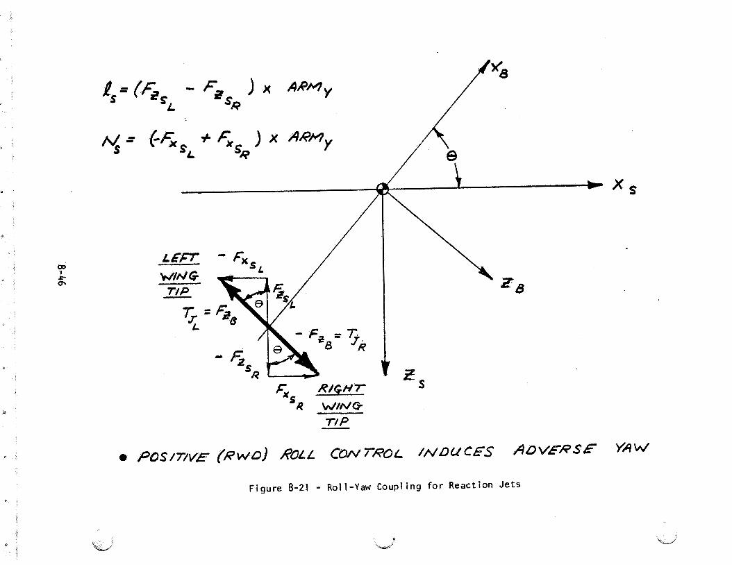
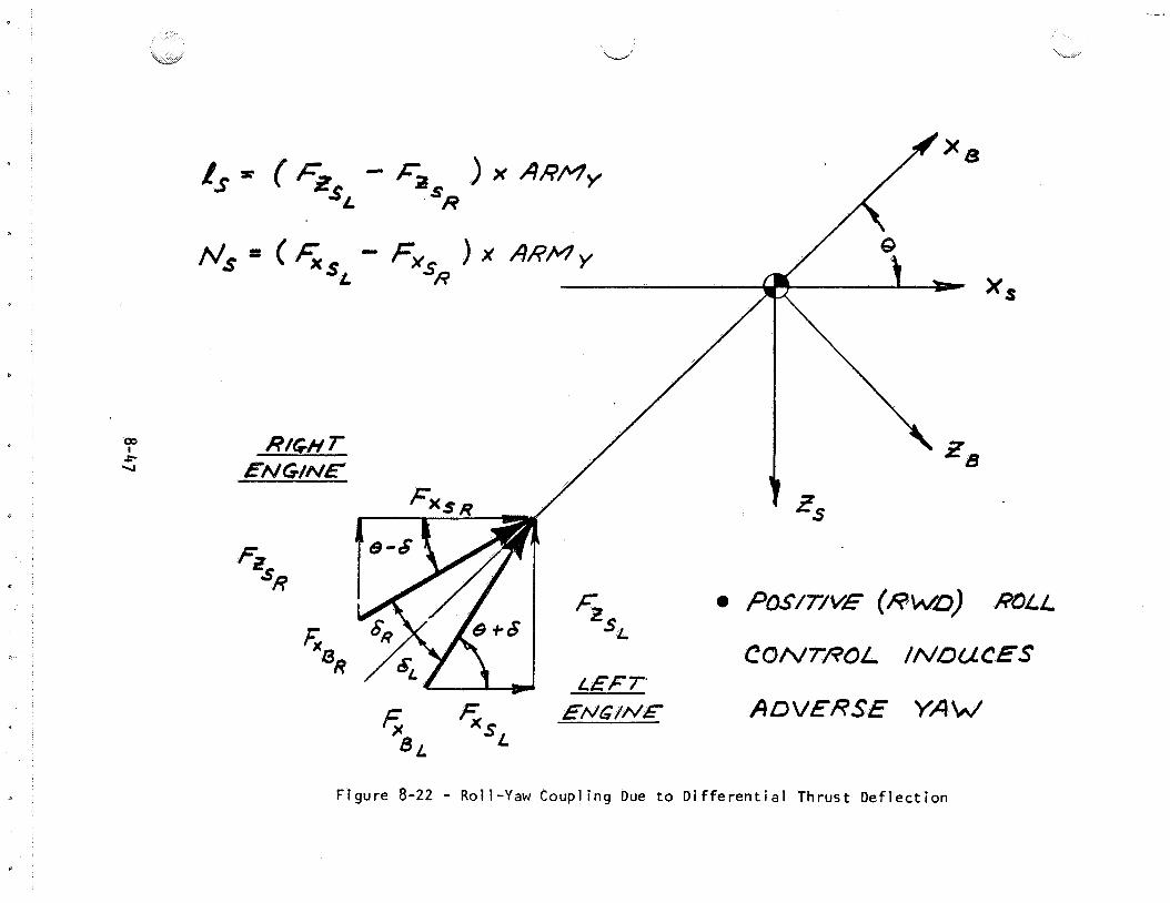
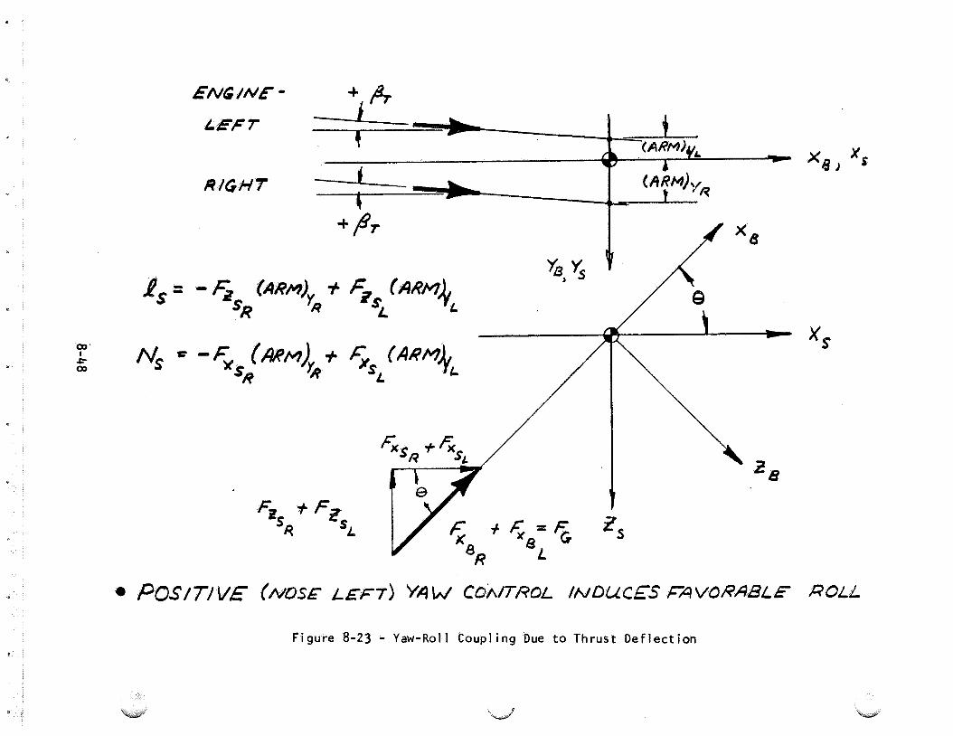
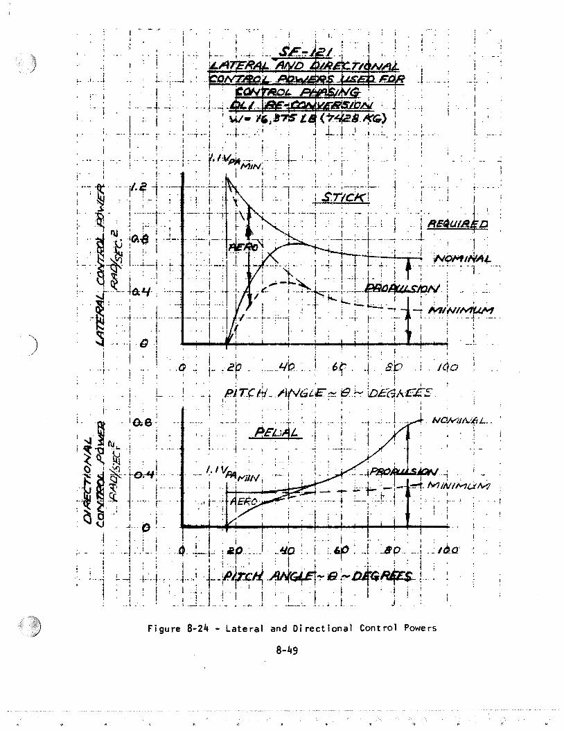
Figure 8-24 - L a t e r a l and D i r e c t i o n a l Control Powers
8-49
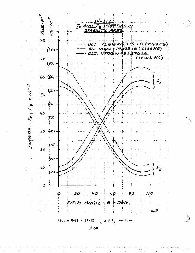
Figure 8-25 - SF-121 I x and I Z I n e r t i a s
8-50
. 9.. i . ra-. .. . i 642:. : ap . / ~ Y Q !
! . I .
! .:. P I J & . . - ~ ~ Y G ; ~ ~ B / D ~ @ . ~ . .j : ' . .-. , . . . I I .
t . j . ! . . !
.++ 1 4 . ' i . I
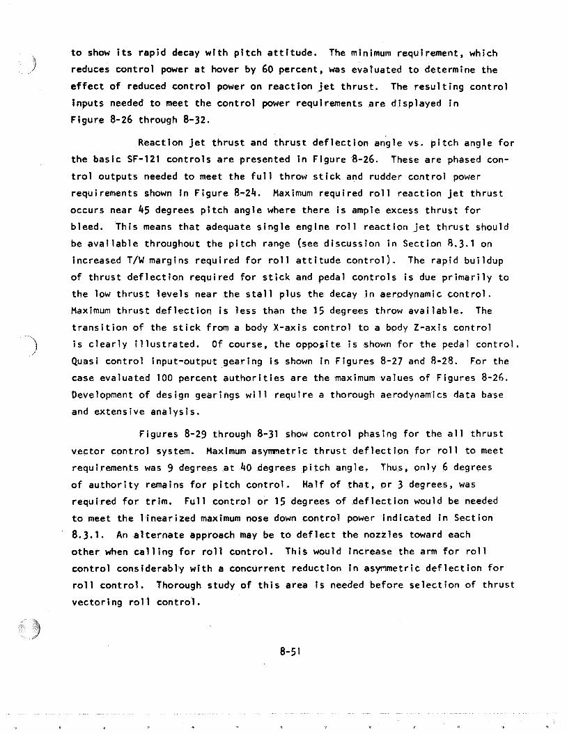
t o show i t s r ap id decay w i t h p i t c h a t t i t u d e . The minimum requirement, which
1 reduces con t ro l power a t hover by 60 percent, was evaluated t o determine the
e f f e c t o f reduced con t ro l power on react ion j e t thrust . The resu l t i ng cont ro l
inputs needed t o meet the con t ro l power requirements a re displayed i n
Figure 8-26 through 8-32.
Reaction j e t t h rus t and t h rus t de f lec t ion a n i l e vs. p i t c h angle f o r
the basic SF-121 con t ro ls are presented i n Figure 8-26. These are phased con-
t r o l outputs needed t o meet the f u l l throw s t i c k and rudder con t ro l power
requirements shown i n Figure 8-24. Maximum requ i red r o l l react ion j e t th rus t
occurs near 45 degrees p i t c h angle where there i s ample excess t h rus t f o r
bleed. This means tha t adequate s ing le engine r o l l react ion j e t t h rus t should
be ava i lab le throughout the p i t c h range (see discussion i n Section 8.3.1 on
increased T/W margins required f o r r o l l a t t i t u d e con t ro l ) . The rap id bui ldup
o f th rus t de f l ec t i on required f o r s t i c k and pedal con t ro ls i s due p r ima r i l y t o
the low t h rus t l eve ls near the s t a l l p lus the decay i n aerodynamic con t ro l .
Maximum th rus t de f l ec t i on i s less than the I 5 degrees throw ava i lab le . The
t r a n s i t i o n o f the s t i c k from a body X-axis con t ro l t o a body Z-axis con t ro l
- 1 i s c l e a r l y i l l u s t r a t e d . O f course, the opposite i s shown f o r the pedal con t ro l . 'i'
Quasi cont ro l input-output gearing i s shown i n Figures 8-27 and 8-25. For the
case evaluated 100 percent au tho r i t i e s a re the maximum values o f Figures 8-26.
Development o f design gearings w i l l requ i re a thorough aerodynamics data base
and extensive analysis.
Figures 8-29 through 8-31 show cont ro l phasing f o r the a1 1 t h rus t
vector con t ro l system. Maximum asymmetric t h rus t de f l ec t i on f o r r o l l t o meet
requirements was 9 degrees a t 40 degrees p i t c h angle. Thus, only 6 degrees
o f au tho r i t y remains f o r p i t c h con t ro l . Ha l f o f that , o r 3 degrees, was
required f o r t r i m . F u l l con t ro l o r I S degrees o f de f l ec t i on would be needed
t o meet the l i near i zed maximum nose down con t ro l power indicated i n Section
8.3.1. An a l t e rna te approach may be t o de f l ec t the nozzles toward each
other when c a l l i n g f o r r o l l cont ro l . This would increase the arm f o r r o l l
con t ro l considerably w i t h a concurrent reduct ion i n asymmetric de f l ec t i on f o r
r o l l cont ro l . Thorough study o f t h i s area i s needed before se lec t ion of th rus t
vector ing r o l l con t ro l .
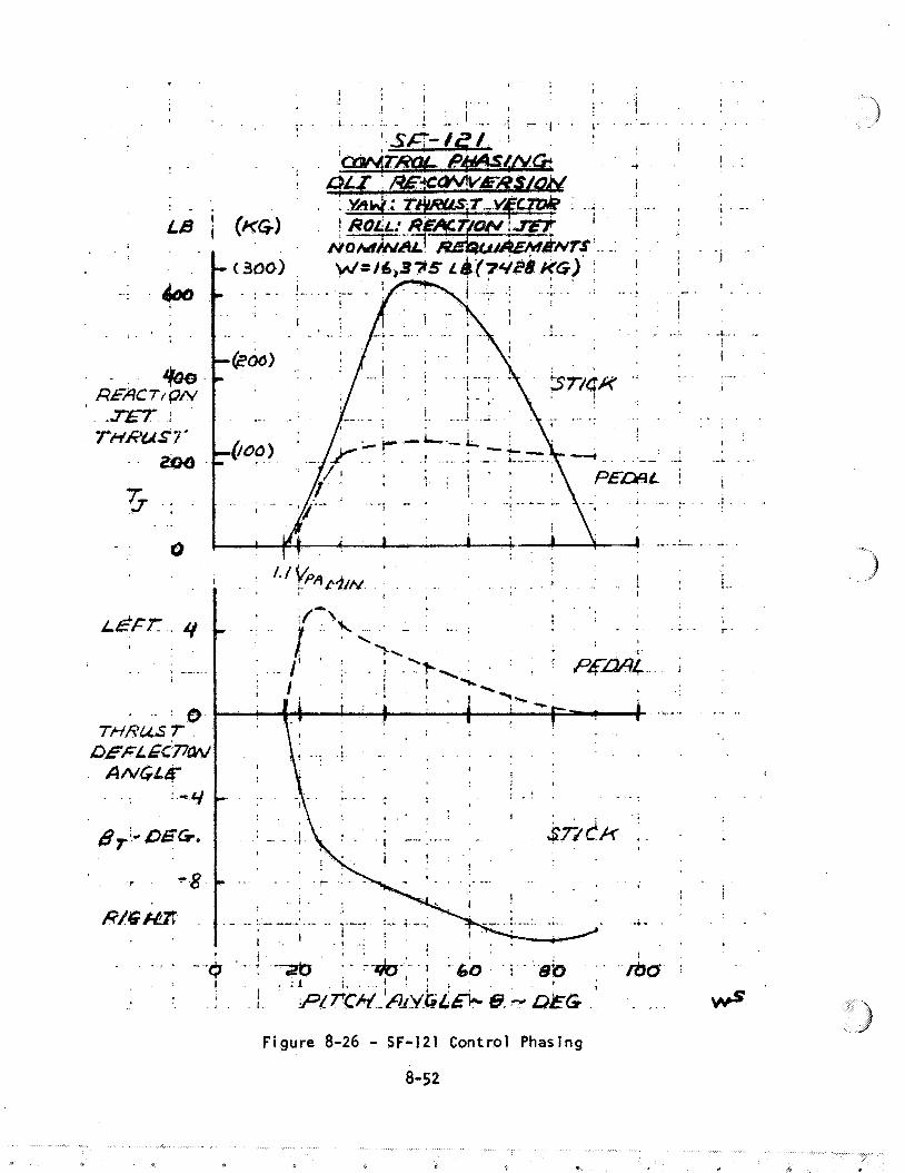
Figure 8-26 - SF-121 Control Phasing
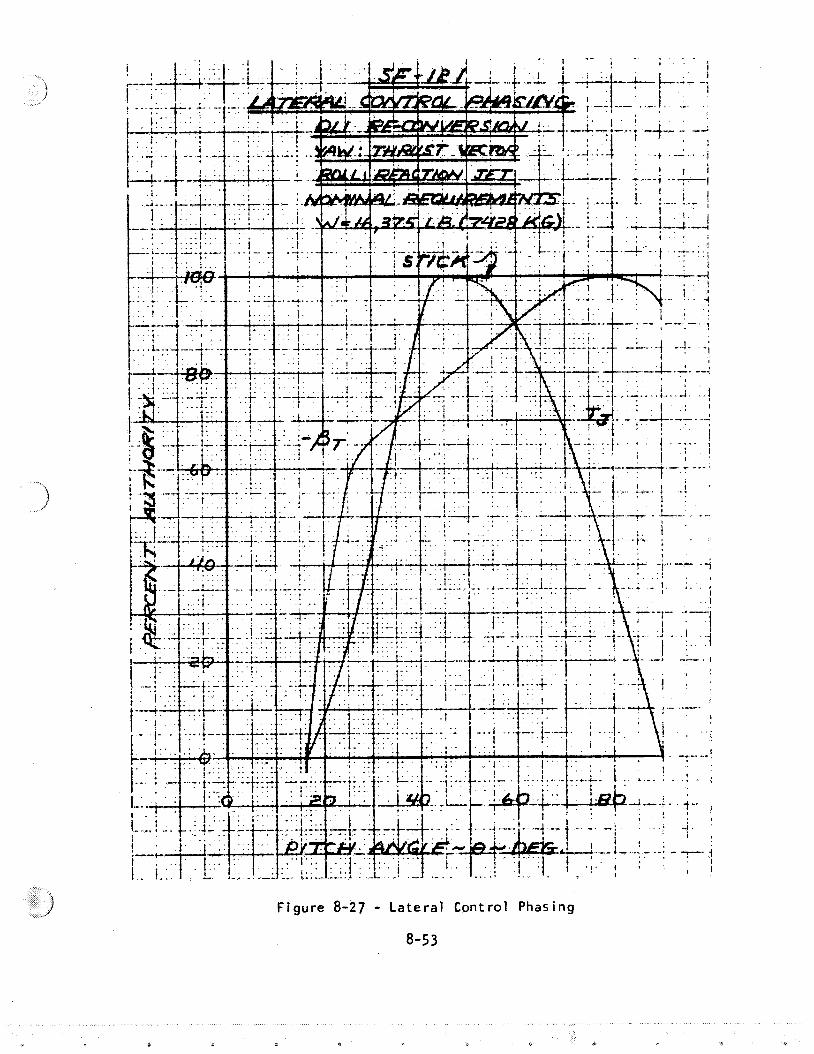
Figure 8-27 - L a t e r a l Control Phasing
8-53
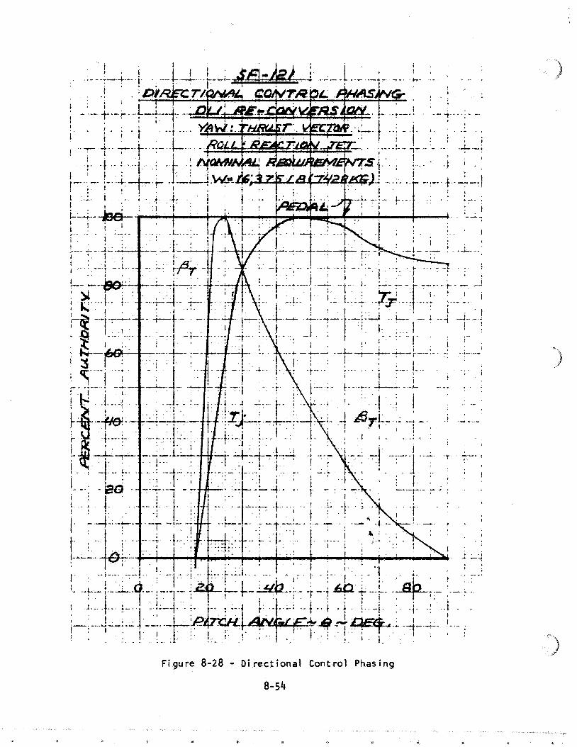
Figure 8-28 - D i rec t iona l Control Phasing
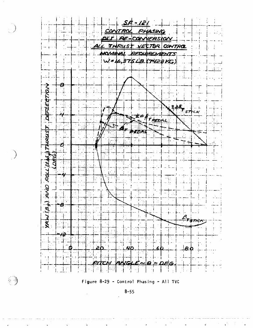
Figure 8-29 - Control Phasing - A l l TVC
8-55
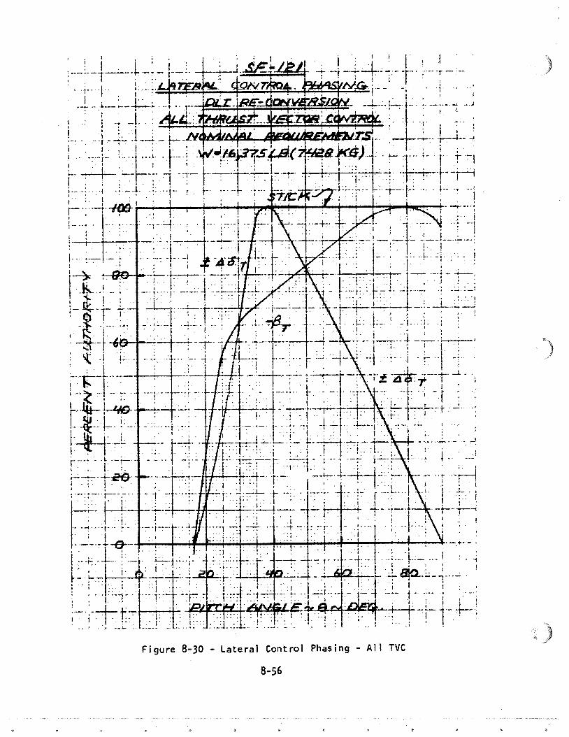
Figure 8-30 - Lateral Control Phasing - A1 1 TVC
8-56
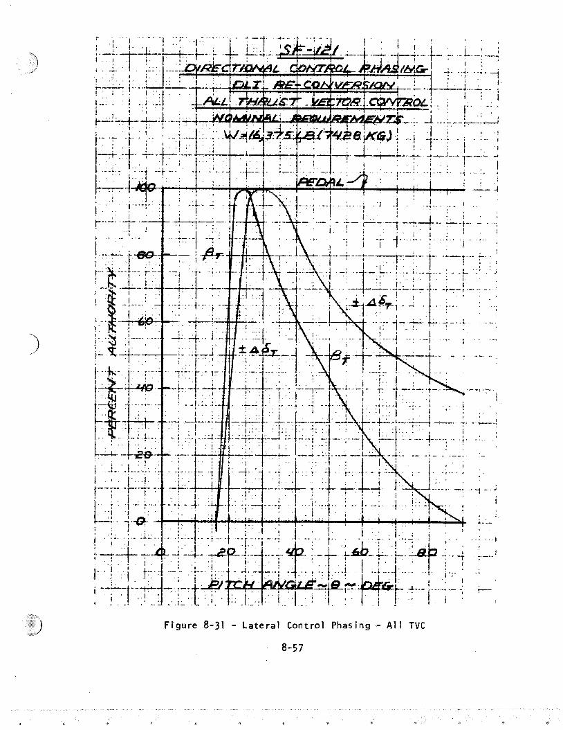
Figure 8-31 - L a t e r a l Control Phasing - A l l TVC
8-57
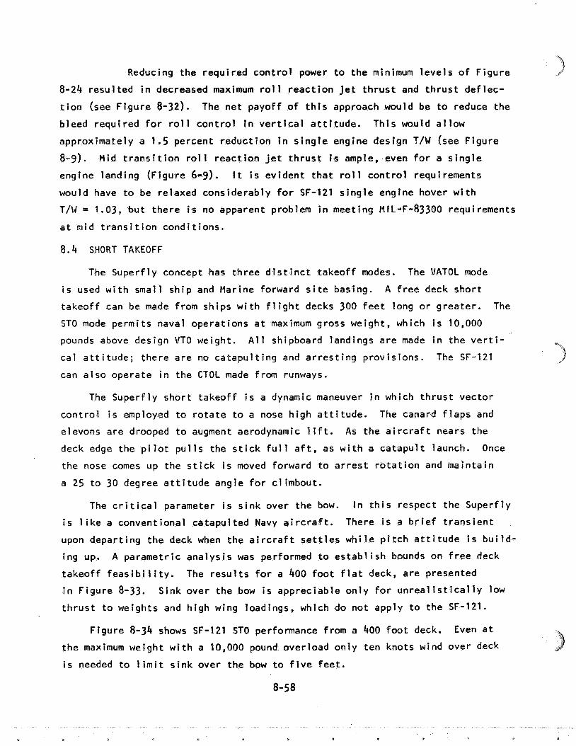
Reducing the required con t ro l power t o the minimum leve ls o f Figure
8-24 resu l ted i n decreased maximum r o l l reac t ion j e t t h rus t and t h rus t def lec-
t i o n (see Figure 8-32). The net payof f o f t h i s approach would be t o reduce the
bleed required f o r r o l l con t ro l i n v e r t i c a l a t t i t u d e . This would a l low
approximately a 1.5 percent reduct ion i n s i ng le engine design T/W (see Figure
8-9). Hid t r a n s i t i o n r o l l react ion j e t t h rus t i s ample,.even f o r a s i ng le
engine landing ( ~ i ~ u r e 6-9). It i s evident t ha t r o l l con t ro l requirements
would have t o be relaxed considerably f o r SF-121 s ing le engine hover w i t h
T/V = 1.03, but there i s no apparent problem i n meeting MIL-F-83300 requirements
a t mid t r a n s i t i o n condi t ions.
8.4 SHORT TAKEOFF
The Superf ly concept has three d i s t i n c t takeoff modes. The VATOL mode
i s used w i t h small ship and Harine forward s i t e basing. A f r ee deck short
takeof f can be made from ships w i t h f l i g h t decks 300 f ee t long o r greater. The
ST0 mode permits naval operations a t maximum gross weight, which I s 10,000
pounds above design VTO weight. A l l shipboard landings are made i n the v e r t i -
ca l a t t i t ude ; there are no catapu l t ing and a r res t ing provisions. The SF-121
can a lso operate i n the CTOL made from runways.
The Superf ly short takeoff i s a dynamic maneuver i n which th rus t vector
con t ro l i s employed t o r o ta te t o a nose h igh a t t i t ude . The canard f l aps and
elevons are drooped t o augment aerodynamic l i f t . As the a i r c r a f t nears the
deck edge the p i l o t p u l l s the s t i c k f u l l a f t , as w i t h a catapu l t launch. Once
the nose comes up the s t i c k i s moved forward t o a r res t r o t a t i o n and maintain
a 25 t o 30 degree a t t i t u d e angle f o r climbout.
The c r i t i c a l parameter i s s ink over the bow. I n t h i s respect the Superf ly
i s l i k e a conventional catapulted Navy a i r c r a f t . There i s a b r i e f t rans ien t
upon depart ing the deck when the a i r c r a f t s e t t l e s wh i le p i t c h a t t i t u d e i s bu i l d -
ing up. A parametric analysis was performed t o es tab l i sh bounds on f r ee deck
takeoff f e a s i b i l i t y . The resu l t s f o r a 400 f oo t f l a t deck, are presented
i n Figure 8-33. Sink over the bow i s appreciable only f o r u n r e a l i s t i c a l l y low
t h rus t t o weights and h igh wing loadings, which do not apply t o the SF-121.
Figure 8-34 shows SF-121 ST0 performance from a 400 f oo t deck. Even a t
the maximum weight w i t h a 10,000 pound overload on ly ten knots wind over deck
i s needed t o l i m i t s ink over the bow t o f i v e feet.
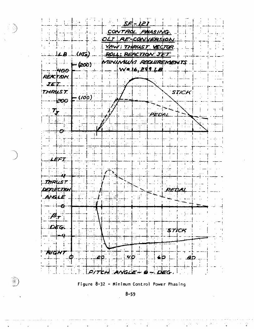
Figure 8-32 - Minimum Control Power Phasing
8-59
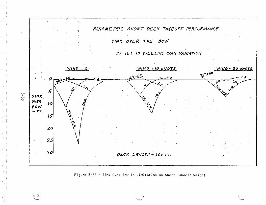
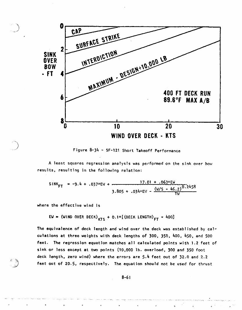
SINK OVER BOW - FT
WIND OVER DECK - KTS
Figure 8-34 - SF-121 Short Takeoff Performance
A leas t squares regression analysis was performed on the s ink over bow
resu l t s , r esu l t i ng i n the fo l lowing re l a t i on :
where the e f f e c t i v e wind i s
EW - (WIND OVER DECK)^^^ + O.I*I(DECK LENGTH)^^ - 4001
The equivalence of deck length and wind over the deck was establ ished by cat -
cu la t ions a t three weights w i t h deck lengths of 300, 350, 400, 450, and 500
feet. The regression equation matches a l l ca lcu la ted po in ts w i t h 1.2 fee t o f
s i nk o r less except a t two po in ts (10,000 l b . overload, 300 and 350 f oo t
deck length, zero wind) where the e r ro rs a re 5.4 feet out o f 32.0 and 2.2
feet ou t o f 20.5, respect ively. The equation should not be used f o r th rus t
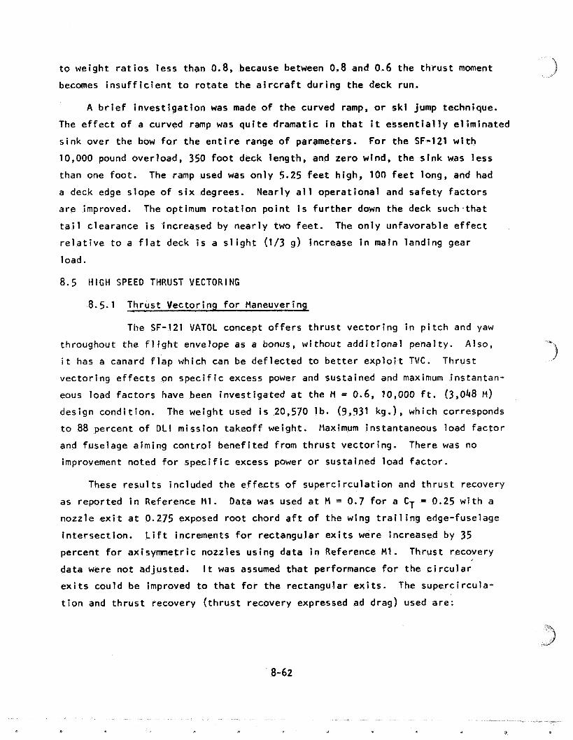
t o weight r a t i o s less than 0.8, because between 0.8 and 0.6 the t h rus t moment
becomes i n s u f f i c i e n t t o r o ta te the a i r c r a f t dur ing the deck run.
A b r i e f i nves t iga t ion was made o f the curved ramp, o r s k i Jump technique.
The e f f e c t o f a curved ramp was q u i t e dramatic i n t ha t i t essentially el iminated
s ink over the bow f o r the e n t i r e range o f parameters. For the SF-121 w i t h
10,000 pound overload, 350 f oo t deck length, and zero wind, the s ink was less
than one foot . The ramp used was on ly 5.25 f ee t high, 100 f ee t long, and had
a deck edge slope o f s i x degrees. Nearly a l l operat ional and safety fac tors
are improved. The optimum r o t a t i o n po in t i s f u r t he r down the deck such. that
t a i l clearance i s increased by near ly two fee t . The on ly unfavorable e f f e c t
r e l a t i v e t o a f l a t deck i s a s l i g h t (1/3 g) increase i n main landing gear
load.
8.5 HIGH SPEED THRUST VECTORING
8.5.1 Thrust Vectoring f o r Maneuvering
The SF-121 VATOL concept o f f e r s th rus t vector ing i n p i t c h and yaw
throughout the f l i g h t envelope as a bonus, without add i t i ona l penalty. Also, h
i t has a canard f l a p which can be def lec ted t o be t t e r e x p l o i t TVC. Thrust
vector ing e f f ec t s on spec i f i c excess power and sustained and maximum instantan-
eous load fac to rs have been invest igated a t the H = 0.6, 10,000 f t . (3,048 M)
design condi t ion. The weight used i s 20,570 Ib. (9,931 kg.), which corresponds
t o 88 percent o f DL1 mission takeoff weight. Haximum instantaneous load fac to r
and fuselage aiming con t ro l benef i ted from th rus t vectoring. There was no
improvement noted f o r s p e c i f i c excess power o r sustained load fac to r .
These resu l t s included the e f fec ts of superc i rcu la t ion and th rus t recovery
as reported i n Reference t l l . Data was used a t t4 = 0.7 f o r a CT = 0.25 w i t h a
nozzle e x i t a t 0.275 exposed roo t chord a f t o f the wing t r a i l i n g edge-fuselage
in tersect ion. L i f t increments f o r rectangular e x i t s were increased by 35
percent f o r a x i s y m e t r i c nozzles using data i n Reference M I . Thrust recovery , data were not adjusted. I t was assumed tha t performance f o r the c i r c u l a r
e x i t s could be improved t o tha t f o r the rectangular e x i t s . The superci rcula-
t i o n and t h rus t recovery ( th rus t recovery expressed ad drag) used are:
A c ~ 1. 0,0018 per degree6T
A C ~ ~ IN = -0.00013 per degree 16~1
A C L ~ = 0.001 13 per degree
ACM = 0
A canard configuration i s we l l su i ted t o e x p l o i t t h rus t vector ing by
use o f a canard upload t o t r i m p o s i t i v e (nozzle down) t h rus t de f lec t ion . This
bene f i t i s displayed i n the power on l i f t curve o f Figure 8-35. For the bas ic
SF-121, t h rus t de f l ec t i on used was t ha t which could be trimmed w i t h a maximum
25 degree canard f l a p def lec t ion. L i f t shown f o r the improved canard was
based upon a doubled canard f l a p ef fect iveness ( t h i s could be obtained w i t h
lower canard sweep, increased canard area, o r powered systems). I f wing t r a i l -
ing edge f l a p t r i m i s used a small increase i n power-on l i f t I s obtained w i t h
negative t h rus t d e f l e c t ions (Figure 8-36). However, these 1 i f t benef i t s d i d
not r e s u l t i n improved maneuver performance i n a c l ass i ca l sense. Normal
acce lera t ion (nZ) a t a g iven angle o f a t tack i s increased but f l i g h t path
acce lera t ion (nx) i s decreased ( ~ i g u r e 8-37). This r e s u l t i s a l so re f lec ted
i n reduced s p e c i f i c excess power vs. normal acce lera t ion ( ~ i g u r e s 8-30 and
8-39). It should be noted t ha t the penal t ies decrease w i t h increasing nz as
the t h rus t de f l ec t i on approaches i t s theore t i ca l optimum. Sustained load
fac to r a t zero nx i s essen t ia l l y unaffected w l t h canard t r i m but i s degraded
w i t h wing f l a p t r i m .
Thrust vector de f l ec t i on increases d i r e c t t h rus t l i f t , decreases
f l i g h t path t h rus t and f o r the SF-121 creates a moment which must be trimned
out . A bene f i t i s derived a t constant load fac to r only i f the incremental
drag from trimming the t h rus t vector moment p lus reduced wing-body induced
drag i s less than the penalty due t o decreased f l i g h t path th rus t . That i s ,
excess t h rus t must be increased. This e f f e c t was not achieved on the SF-121
because the a i rp lane drag po lar had already been optimized t o meet the sustained
maneuver requirement. A bene f i t may be shown f o r a less optimum canard and
wing f l a p combination o r v i a opt imizat ion w i t h t h rus t vector ing included.
Substant ia l payof f can be shown f o r th rus t vector ing i n combat
(Figure 8-40). D i r ec t 1 i f t con t ro l i s generated through simul taneous th rus t
vector and canard t r i m con t ro l def lec t ion. Fuselage aiming con t ro l o f f e r s
8-63

Figure 8-35 - E f f e c t o f Thrust Vector ing on Li f t -Canard Trim
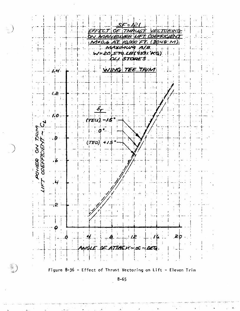
Figure 8-36 - E f f e c t o f Thrust Vectoring on L i f t - Elevon Tr im
8-65
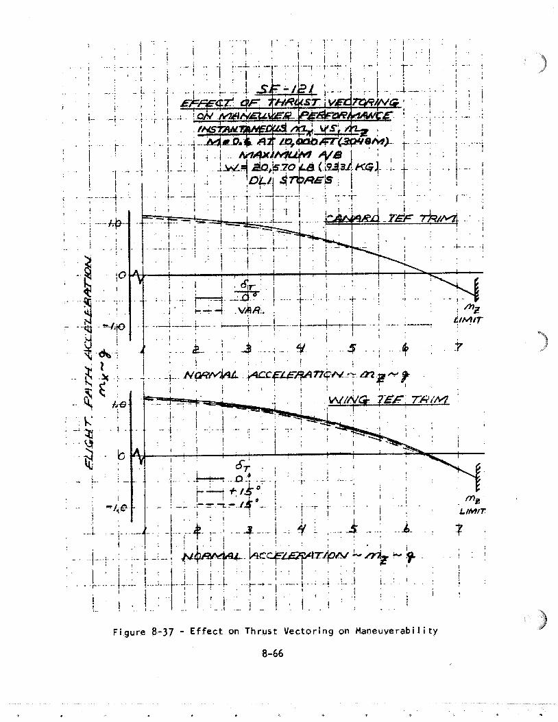
Figure 8-37 - E f f e c t on Thrust Vectoring on Maneuverabi 1 i t y
8-66
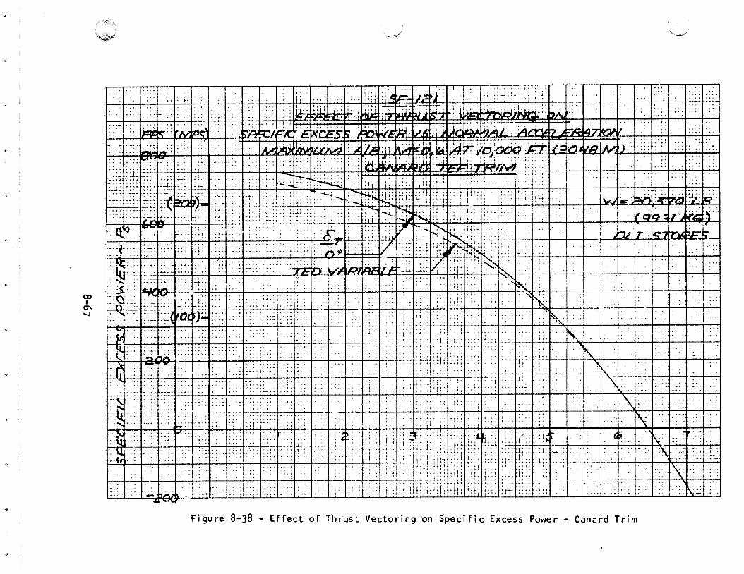
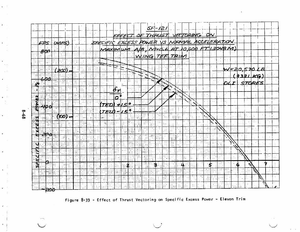
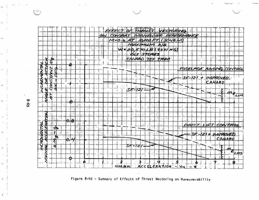
c a p a b i l i t y t o independently change fuselage e l e v a t i o n angle Cup o r down) f o r ;I t a r g e t t rack ing w i thou t change i n f l i g h t path. This i s achieved by t rad ing o f f
wing l i f t w i t h t h r u s t vec tor p l u s canard l i f t . During a i r - to -ground gunnery,
fuselage aiming provides more t ime on t a r g e t and l e v e l f l i g h t s t r a f i n g maneuvers
can b~ done w i t h the nose depressed. A i r - t o - a i r a p p l i c a t i o n provides h igher
aspect conversion c a p a b i l i t y w i t h more and longer f i r i n g .oppor tun i t ies .
8 .5 .2 Thrust Vector ing For Supersonic Cruise
A small improvement i n c r u i s e drag was shown f o r t h r u s t vec to r ing
a t t4 = 1.6 a t 40,000 f t . (12,192 M) . Superc i r cu la t i on and t h r u s t recovery
data used from Reference 6 ( a t M = 1 . 2 ) are:
A c ~ 0
"DM I N -0.00028 per degree
ACL 0.0008 per degree 16T1
ACM 0
The optimum t h r u s t vec tor angle o f 2.0 degrees was determined from the express-
expression:
Drag c o e f f i c i e n t was reduced by 0.0006 w i t h a r e s u l t a n t 1.3 percent increase i n
s p e c i f i c range. Th is small e f f e c t was due t o the 40,000 f o o t dash a l t i t u d e
being much below optimum.
Most o f the technology requi rements fo r the SF-121 are comnon t o advanced
f i g h t e r s i n general. The degree t o which s t r u c t u r a l weight, f o r instance, i s
reduced w i l l in f luence the s i z e o f the a i rp lane , but i s u n l i k e l y t o determine
f e a s i b i 1 i t y . The payof fs f o r h igh speed t h r u s t vec tor ing appear very uncer-
t a i n , p a r t i c u l a r l y t h r u s t induced e f f e c t s .
The p r i n c i p a l issues center around the VATOL mode o f operat ion. The X - 1 3
demonstrated the bas ic f e a s i b i l i t y o f VATOL from a land s i t e over 20 years ago.
Val i d doubts remain about the opera t iona l s u i t a b i l i t y o f VATOL. The major
unce r ta in t i es are:
o F l y i n g q u a l i t i e s i n t r a n s i t i o n o A i r c r a f t / s h i p aerodynamic f low i n t e r a c t i o n s o A t t i t u d e c o n t r o l system power and response o I n l e t recovery and d i s t o r t i o n dur ing t r a n s i t i o n o Propuls ion induced spray o P i l o t v i s i b i l i t y and landing a i d requi rements
The spray quest ion can o n l y be resolved by f u l l scale j e t engine t e s t s
above water. There are several fundamental l y d i f f e r e n t f low phenomena a t work, -1
1 and r e l i a b l e s c a l i n g o f small scale t e s t s i s quest ionable. /
The o the r issues can be e f f e c t i v e l y addressed by developing a powered
model wind tunnel data base t o cover VATOL t r a n s i t i o n boundaries and by
manned moving base s imu la t i on o f t r a n s i t i o n and docking on a ship.
The land based VATOL landing should n o t be a major r i s k , s ince the ra the r
p r i m i t i v e X-13 accompl ished i t many times. But the e f f e c t s o f j e t b l a s t on
ground eros ion, f o re ign ob jec t damage and re ingest ion requ i re considerable
a t t e n t i o n . R e l a t i v e impact o f these concerns on design development and the
need f o r t e s t i n g and ana lys is t o resolve them i s discussed i n the f o l l o w i n g
paragraphs . 9.1 TRANSON l C AND SUPERSON l C AERODYNAMICS
S i z i n g c r i t e r i a f o r t he SF-121 described i n Sect ion 8.1 are Supersonic
i n te rcep t radius, s i n g l e engine v e r t i c a l landing t h r u s t t o weight and 6.2 g
sustained load f a c t o r a t M = 0.6 10,000 f e e t (3,048 M) a1 t i tude. A breakdown
o f the DL1 mission f u e l usage i s presented below i n Table 9-1 t o a i d d i s -
cussion o f the e f f e c t s o f design requirements on SF-121 s i z i n g .
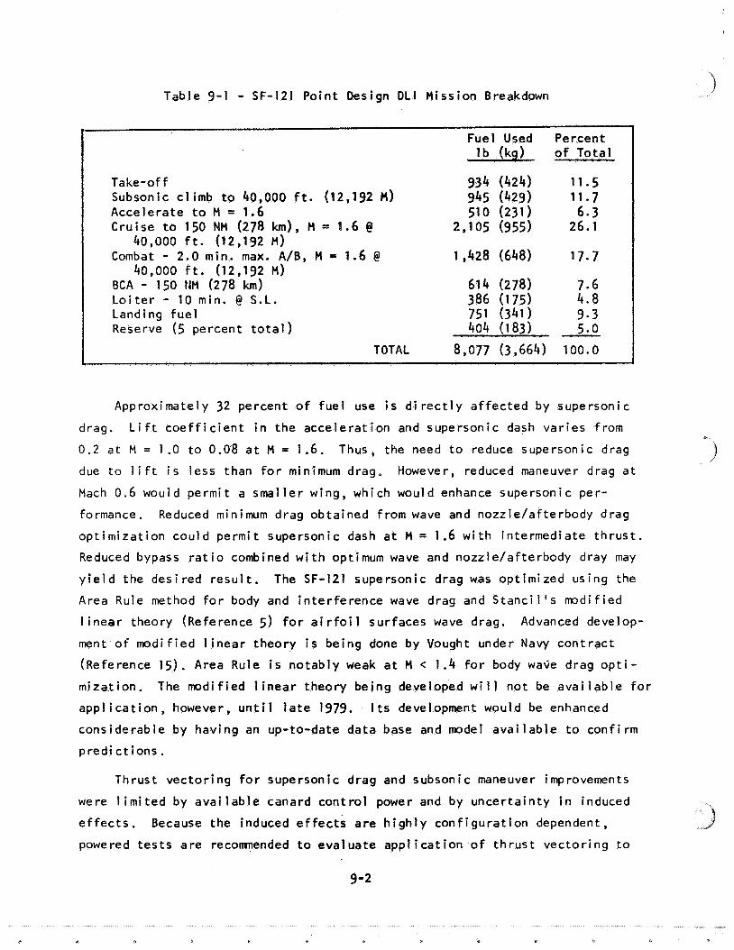
Table 9-1 - SF-121 Po in t Design DL1 Miss ion Breakdown
Fuel Used Percent l b (kg) of To ta l
Take-of f 934 (424) 11.5 Subsonic c l imb t o 40,000 ft. (12,192 H) 945 (429) 11.7 Accelerate t o M = 1.6 510 (231) 6.3 Cruise t o 150 NM (278 km), ll = 1.6 @ 2,105 (955) 26.1
40,000 ft. (12,192 n) Combat - 2.0 min. max. A/B, M = 1.6 @ 1,428 (648) 17.7
40,000 f t . (12,192 M) BCA - 150 NM (278 km) 614 (278) 7.6 L o i t e r - 10 min. @ S.L. 386 (175) 4.8 Landing f u e l 751 (341) 9.3 Reserve (5 percent t o t a l ) 404 (183) 5.0
TOTAL 8,077 (3,664) 100.0
Approximately 32 percent o f f ue l use i s d i r e c t l y a f f e c t e d by supersonic
drag. L i f t c o e f f i c i e n t i n the acce lera t ion and supersonic dash var ies from m
0.2 a t M = 1 .0 t o 0.08 a t M = 1.6. Thus, the need t o reduce supersonic drag
due t o 1 i f t i s less than f o r minimum drag. However, reduced maneuver drag a t 1
Mach 0.6 would permi t a smal le r wing, which would enhance supersonic per-
formance. Reduced minimum drag obta ined from wave and nozzle/afterbody drag
op t im iza t i on cou ld permi t supersonic dash a t M = 1.6 w i t h Intermediate t h r u s t .
Reduced bypass r a t i o combined wi t h op t i mum wave and nozzl e/afterbody dray may
y i e l d the desi red r e s u l t . The SF-121 supersonic drag was opt imized using the
Area Rule method f o r body and in te r fe rence wave drag and S t a n c i l ' s modi f ied
1 inear theory ( ~ e f e r e n c e 5) f o r a i r f o i 1 surfaces wave drag. Advanced develop-
ment o f mod i f ied l i n e a r theory i s being done by Vought under Navy con t rac t
( ~ e f e r e n c e 15). Area Rule i s no tab ly weak a t M < 1.4 f o r body waqe drag o p t i -
mizat ion. The modi f ied 1 i near theory being developed w i l l n o t be a v a i l a b l e f o r
appl i c a t i o n , however, u n t i 1 l a t e 1979. I t s development would be enhanced
considerable by having an up-to-date data base and model avai l a b l e t o conf i r m
p red ic t i ons .
Thrust vec to r ing f o r supersonic drag and subsonic maneuver improvements
were l i m i t e d by a v a i l a b l e canard con t ro l power and by uncer ta in ty i n induced
e f f e c t s . Because the induced e f f e c t s a re h i g h l y con f igu ra t i on dependent,
powered t e s t s a re recomnended t o evaluate a p p l i c a t i o n o f t h r u s t vec to r ing t o
the SF-121. Small t h r u s t de f l ec t i ons may o f f e r p o t e n t i a l nozzle/af terbody
drag reduct ions. The rea l key t o e x p l o i t i n g h i g h speed t h r u s t vector ing,
however, i s t o augment the moment c a p a b i l i t y o f the canard.
Subsonic f u e l use i s 24 percent o f the t o t a l . H a l f o f t h i s i s used i n
the subsonic acce le ra t i on t o c l imb speed fo l lowed by c l imb a t the drag r i s e
Mach number. Improved drag due t o l i f t and drag r i s e Mach number a r i s i n g from
continued wing o p t i m i z a t i o n would reduce fue l f o r t h i s segment. These bene-
f i t s would a l s o s p i l l over i n t o re tu rn c r u i s e f u e l savings and improved
t ranson ic maneuver drag. The Mach 0.6 susta ined load f a c t o r requi rement was
s a t i s f i e d w i t h wing and canard v a r i a b l e camber app l ied t o a t h i n uncambered
wing. I t i s poss ib le t h a t b u i l t - i n wing t w i s t and camber w i t h decamber f l aps
f o r supersonic c ru i se would y i e l d b e t t e r o v e r a l l performance.
Subson i c and t ranson i c drag due t o 1 i f t est imates were based on t e s t s o f
a non-representat ive coplanar canard-wing geometry (Reference 3). Wing
lead ing edge f l a p incremental e f f e c t s obta ined from a model w i thou t a canard
appl i e d t o the base1 ine wing w i thout lead ing edge devi ces . Uncer ta in t i es
a r i s i n g from these p r o j e c t i o n s r e s u l t i n a need f o r more representa t ive t e s t
data t o compare w i t h a n a l y t i c a l r e s u l t s . A n a l y t i c a l p red ic t i ons f o r the t e s t
con f igu ra t i on should be made us ing the Bai ley-Bal lhaus o r Jameson techniques
(References 16 and 17 respec t i ve l y ) . Vought i s c u r r e n t l y working t o combine
these op t im iza t i on techniques under NASA cont rac t NAS2-9653.
Questions t o be resolved inc lude:
o Should t w i s t and camber be b u i l t - i n o r in t roduced through maneuvering f 1 aps?
o What i s the in f luence o f t he canard f low f i e l d o f t ranson ic wing c h a r a c t e r i s t i c s ?
o Can a canard and wing be opt imized simultaneously? o Can incremental e f f e c t s be l i n e a r l y superposed w i t h reasonable
accuracy?
Time and resources are not s u f f i c i e n t t o permi t a f u l l wing o p t i m i z a t i o n on
the Phase I I base1 ine model. However, comparison o f the t e s t resul t s w i t h
p red ic t i ons w i l l expedi te f u t u r e wing-canard design op t im iza t i on .
Vought d i d ex tens ive wind tunnel development o f a CTOL canard f i g h t e r
which d i f f e r e d from the SF-121 i n having a much h igher aspect r a t i o (3-8).
Test experience i s summarized i n Figures 9-1 and 9-2, p r o v i d i n g q u a l i t a t i v e
gu ide l ines f o r improving d i r e c t i o n a l s t a b i l i t y and p i tchup. The SF-121
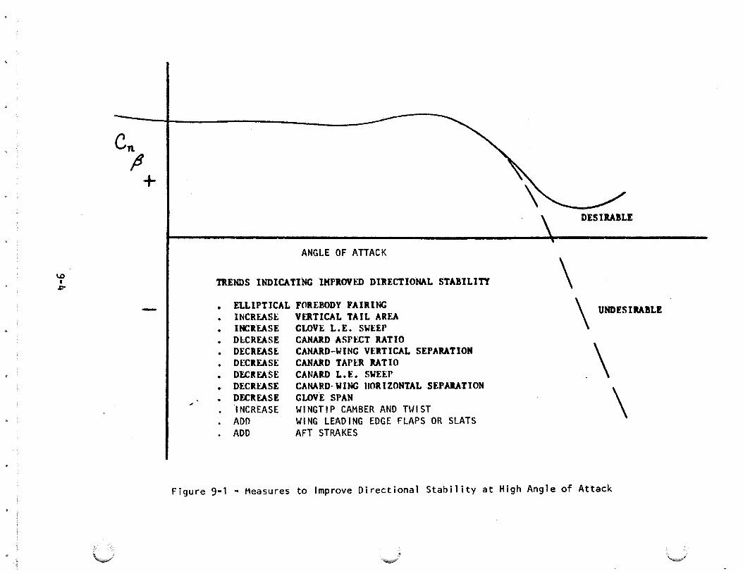
\ DESIRABLE
m
ANGLE OF ATTACK
TRENDS INDICATING IHPROVFD DIRECTIONAL S T A B I L I T Y \ ELLIPTICAL INCREASE INCREASE DLCREASE DECREASE DECREASE DECREASE DECREASE DECREASE 'I NCREASE ADD ADD
FOREBODY PAIRING VERTICAL T A I L AREA CLOVE L . E . SWEEP CANARD A S P W T RATIO CANARD-WING VERTICAL SEPARATION CANARD TAPER RATIO CANARD L . E . SWEEP CANARD- WING 1iORI ZONTAL S E P A M T l O N CLOVE SPAN WINGTIP CAMBER AND TWIST WING LEADING EDGE FLAPS OR SLATS AFT STRAKES
\ UNDESIRABLE
Figure 9-1 - Measures t o Improve D i r e c t i o n a l S t a b i l i t y a t High Angle of Attack
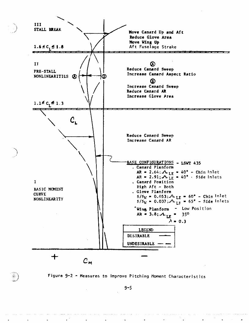
STALL BREAK Uove Canard Up and Aft
PRE- STALL NONLINEARITIES @ Increase Canard Aspect Ratio
Increase Canard Sweep Reduce Canard AR Increase Glove Area
BASIC MOMEhT CURVE NONLINEARITY
Reduce Canard Sweep Increase Canard AR
-BASE CONFIGURATIONS - L S ~ 435 . Canard Planform AR = 2 . 6 4 : A L E 1 40° - Chin I n l e t AR - 2 . 9 1 ; h L E = 40' - S i d e I n l e t s . Canard Pos i t i on High Aft - Both Glove Planform S/SW = 0 . 0 5 3 ; A L E - 60° - Chin I n l e t S /SV = 0 . 0 3 7 ; A L F - 65' - Side I n l e t s
. ~ i ~ ~ Planform - Low P o s i t i o n A R r 3 . 8 ; A = 350 LE
h = 0 . 3 , UNDESIRABLE - -
Figure 9-2 - Measures t o Improve P i tch ing Homent C h a r a c t e r i s t i c s
already incorporates some o f these features. Others a re addressed i n the
recommended research program descr i bed i n Sect i on 10 .O.
9.2 BUFFET CHARACTERI ST I cs
B u f f e t onset l i f t c o e f f i c i e n t i s est imated t o be h ighe r than t h a t re-
q u i r e d t o sus ta in 6.2 g a t M = 0.6 a t 10,000 f t . (3,048 M ) . Primary design
va r iab les inc lude v a r i a b l e camber on the wing and canard, canard and wing
planform, and canard-wing h o r i z o n t a l and v e r t i c a l spacing. The i n f l uence o f
the canard i s complex and d i f f i c u l t t o p r e d i c t . Ea r l y canard separa t ion w i l l
lower b u f f e t onset CL, bu t a canard which i s too r e s i s t a n t t o s t a l l promotes
p i tchup. To f u l l y eva lua te these e f f e c t s wing and canard r o o t bending moment
s t r a i n gauges should be i n s t a l l e d .
B u f f e t i s a l s o a concern i n t r a n s i t i o n , p a r t i c u l a r l y du r ing reconversion
where e x t rernely h igh angles o f a t t a c k w i 1 1 be encountered a t low a i rspeeds.
l n tens i t y o f t h i s b u f f e t could i n f l uence reconversion p r o f i l e s e l e c t i o n and
u l t imate ly c o n t r o l phasing requirements.
9.3 TRANSITION AERODYNAMICS
The data base f o r the t r a n s i t i o n f l i g h t regime i s der ived from Mach 0.6
data on a c o n f i g u r a t i c n which i s non-representat ive i n the very features which
are paramount t o ach iev ing good f l y i n g q u a l i t i e s . Data f o r extremely h igh
angle o f a t t a c k was developed us ing trends f rom a d i f f e r e n t t a i l e d d e l t a wing
con f i gu ra t i on . (See F igure 5-2) The aerodynamic ana lys i s described i n
Sect ion 5.0 and Appendix A was a strenuous e f f o r t t o account f o r every s i g n i -
f i c a n t c o n f i g u r a t i o n d i f f e r e n c e . The r e s u l t i n g aerodynamic c o e f f i c i e n t s a re
a composite o f many t e s t runs. I t i s very ev iden t , p a r t i c u l a r l y i n the
l a t e r a l / d i r e c t i o n a l p r e d i c t i o n s , t h a t powerful and non l i nea r f low phenomena
are a t work. Th i s r e a l i z a t i o n immediately undermines conf idence i n the
(necessary) approach o f 1 i near superpos i t ion o f incremental e f f e c t s . We were
unable t o f i n d any q u a n t i t a t i v e bas i s t o c o r r e c t f o r the s t rong l a t e r a l vor tex
(discussed i n Reference I) which was a major c o n t r i b u t o r t o d i r e c t i o n a l
i n s t a b i l i t y i n the h i g h wing model (so much t h a t tw in v e r t i c a l t a i l s were
destabi 1 i z ing above 20 degrees angle o f a t t a c k ) . The SF-121 was speci f i c a l l y
conf igured t o counter such e f f e c t s (e.g., the wing t r a i l i n g edge i s moved
down and a f t t o s h i e l d the f i n ; the canard i s above the wing t o energize
tops i de f 1 ow) .
i Tests on an accurately defined model w i l l conf i rm the ef fect iveness o f 1 the conf igurat ion refinements and a lso determine the v a l i d i t y o f estimates by
1 inear superposit ion.
9.4 INLET AERODYNAMICS
Hor izontal ramp external compression i n l e t s were selected f o r the SF-121
because o f t h e i r adaptabi 1 i t y t o a wide range o f Mach numbers and angle o f
a t tack condi t ions. The ramps provide a f low tu rn ing e f f e c t a t h igh angle o f
a t tack which reduces d i s t o r t ion. During VATOL t r a n s i t ion i t i s d i s t o r t i o n
index rather than t o t a l pressure recovery which i s important since th rus t
requirements are r e l a t i v e l y low. As the hover condi t ion i s approached
maximum recovery i s important.
Our analysis indicated tha t d i s t o r t i o n o f the SF-121 i n l e t f low due t o
angle o f a t tack i s comparable t o that on the F-14 i n l e t s . The e f f e c t s o f
combined angle o f a t tack and sides1 i p (both can approach 90 degrees a t low
ve loc i t i es ) have not been determined. Performance o f the downst ream i n l e t
could be a problem. The XM2R propuls ion s imulator could be a valuable t o o l
t o implement powered model tes ts t o very high angles.
9.5 PROPULS l ON l NDUCED EFFECTS
The VATOL a i r c r a f t i s l a rge ly f ree from the propuls ion induced e f f ec t s
which plague f l a t r i s e r VTOL a i r c r a f t . I t s a f t exhaust nozzles and v e r t i c a l
a t t i t u d e minimize propulsion induced ground e f f ec t s . There may be a s l i g h t
e f f ec t when the nozzles are used t o r o ta te the a i r c r a f t f o r ST0 1 i f t o f f .
Nozzle de f l ec t i on f o r cont ro l w i l l induce higher f low ve loc i t i es on the nozzle
s ide opposite the de f lec t ion . This would be expected t o be favorable, but
knowledge o f i t s magnitude i s essent ia l f o r con t ro l system development.
Powered model tes ts i n crosswinds and i n the presence o f a simulated ship
and p la t fo rm w i 1 1 be required t o assess t h i s problem.
10.0 RESEARCH PROGRAM
Th is sec t i on presents a research program formulated t o resolve the aero-
dynamic u n c e r t a i n t i e s described i n Sect i on 9.0. Recommended aerodynamic
ana lys i s methods t o be developed have been i n teg ra ted i n t o a wind tunnel t e s t
p lan. The r e s u l t i s a t o t a l research program which c l o s e l y r e l a t e d a n a l y t i c a l
development t o a known concise t e s t data base. The analyses are proposed as
d i s t i n c t , p a r a l l e l programs beyond the scope o f the model development c o n t r a c t .
Methods w i l l be developed and app l i ed f o r guidance o f subsequent wind tunnel
t e s t s . Each t e s t o r a n a l y t i c a l a c t i v i t y i s s t a t e d w i t h a l i s t o f ob jec t i ves
and t e s t o r ana lys i s va r i ab les . The o b j e c t i v e s r e l a t e d i r e c t l y t o the uncer-
t a i n t i e s o f Sect ion 9.0, p l u s re levant data needed t o de f i ne b a s i c aerodynamic
c h a r a c t e r i s t i c s . Model va r i ab les presented show the f u l l range o f model p a r t s
requi red. Test va r i ab les are shown t o i l l u s t r a t e a minimum l e v e l needed f o r
eva lua t i on o f u n c e r t a i n t i e s and t o de f i ne b a s i c aerodynamic design data.
Analys is va r i ab les are o r i e n t e d s p e c i f i c a l l y t o cover t he u n c e r t a i n t i e s and
deta i l e d performance requi rements. Before g e t t i n g i n t o de ta i 1s o f the research
program we w i l l f i r s t descr ibe the proposed Phase I I wind tunnel model i t s e l f .
10.1 WIND TUNNEL MODEL
10.1.1 Basel ine Model Concept
A h i g h l y v e r s a t i l e , modular wind tunnel model i s proposed t o
implement the t e s t program described i n Sect ion 10.2. The model sca le and
cons t ruc t i on concept assure c o m p a t i b i l i t y w i t h two XM2R compact p ropu ls ion
s imu la tors . The XM2R i s a small a x i a l f l ow compressor d r i ven by h igh pressure
a i r , and i s capable o f s imu la t i ng a wide range o f engine ope ra t i ng cond i t i ons .
I t may prove even more val uable f o r low speed VSTOL t r a n s i t ion t e s t i n g than i n
i t s intended h i g h speed f l i g h t mode. The model w i l l i n i t i a l l y be tes ted i n a
f low-through mode.
F igure 10-1 shows the modular cons t ruc t i on proposed fo r Phase I I.
The h e a r t o f the model i s a s t e e l box s t r u c t u r e which can house an i n t e r n a l
s t r a i n gage balance when s t i n g mounted. A1 t e r n a t i v e l y , a top o r bottom
mounted b lade can support the model and supply compressed a i r t o the XM2R
s imula tors when i n s t a l l e d . A l l the o t h e r model p a r t s a t t a c h t o the cen t ra l
core w i thou t i n t e r f e r i n g w i t h the balance o r i n l e t ducts. The wings and
empannage are a t tached by s t e e l tangs t o permi t var ious mounting l o c a t ions.
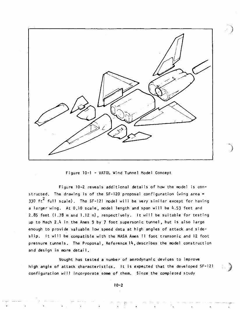
Figure 10-1 - VATOL Wind Tunnel Model Concept
F igure 10-2 reveals a d d i t i o n a l d e t a i l s o f how the model i s con-
s t ruc ted . The drawing i s o f the SF-120 proposal con f igu ra t i on (wing area = 2
330 f t f u l l sca le) . The SF-121 model w i l l be very s i m i l a r except f o r having
a l a r g e r wing. A t 0.10 scale, model length and span w i 1 1 be 4.53 f e e t and
2.85 fee t (1.78 m and 1 . I 2 m), r espec t i ve l y . I t w i l l be s u i t a b l e f o r t e s t i n g
up t o Mach 2.4 i n the Ames 9 by 7 f o o t supersonic tunnel , but i s a l so l a rge
enough t o prov ide valuable low speed data a t h igh angles o f a t t a c k and s ide-
s l i p . I t w i l l be compatible w i t h the NASA Ames 1 1 f o o t t ranson ic and 12 f o o t
pressure tunnels. The Proposal, Reference 14,describes the model cons t ruc t i on
and design i n more d e t a i l .
Vought has t e s t e d a number o f aerodynamic devices t o improve
h i g h angle o f a t t a c k c h a r a c t e r i s t i c s . I t i s expected t h a t the developed SF-121
con f igu ra t i on w i 1 1 incorpora te some o f them. Since the completed study
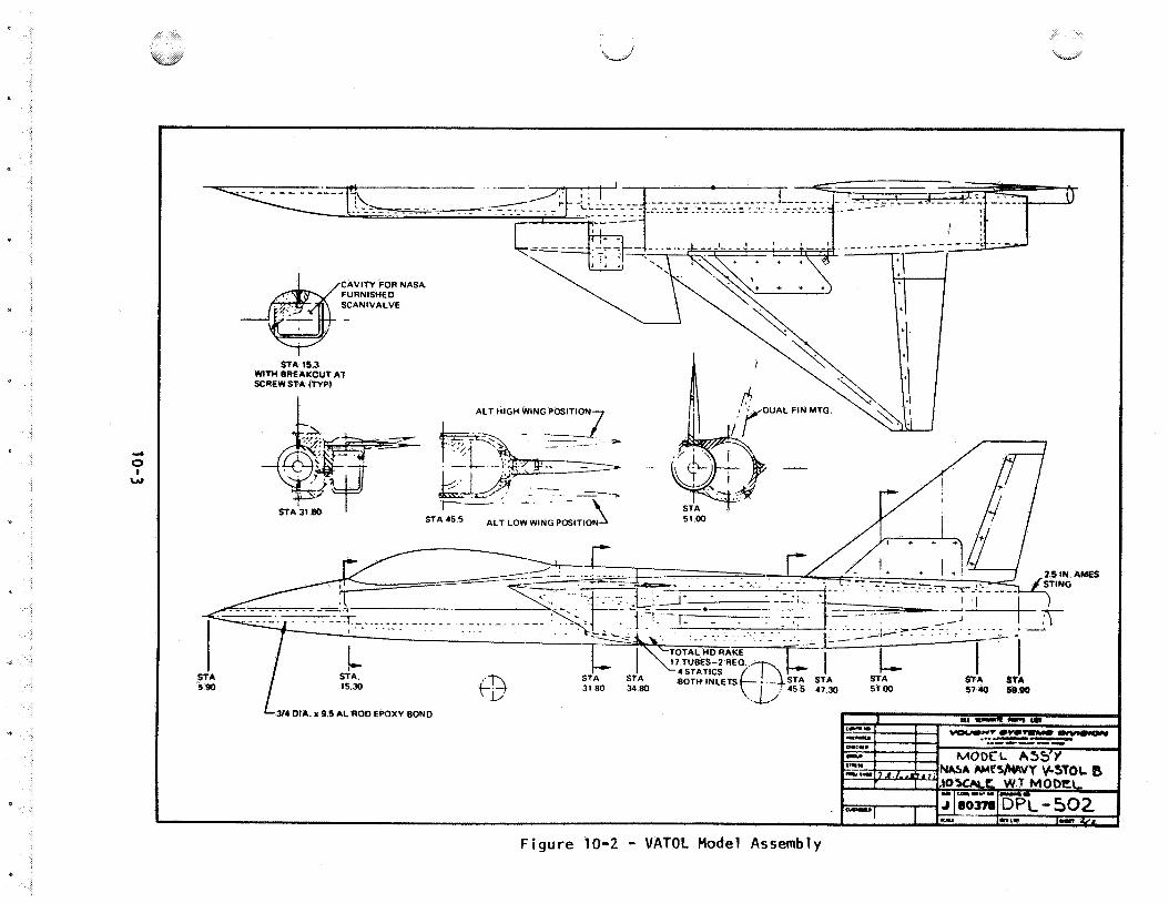
WITW BREAKOUT A l SCREW STA fTYPl
'' ALT LOW WING POSITION
3 4 DIA. x 9.5 AL ROD EPOXY BOND
F igure 10-2 - VATOL Model Assembly
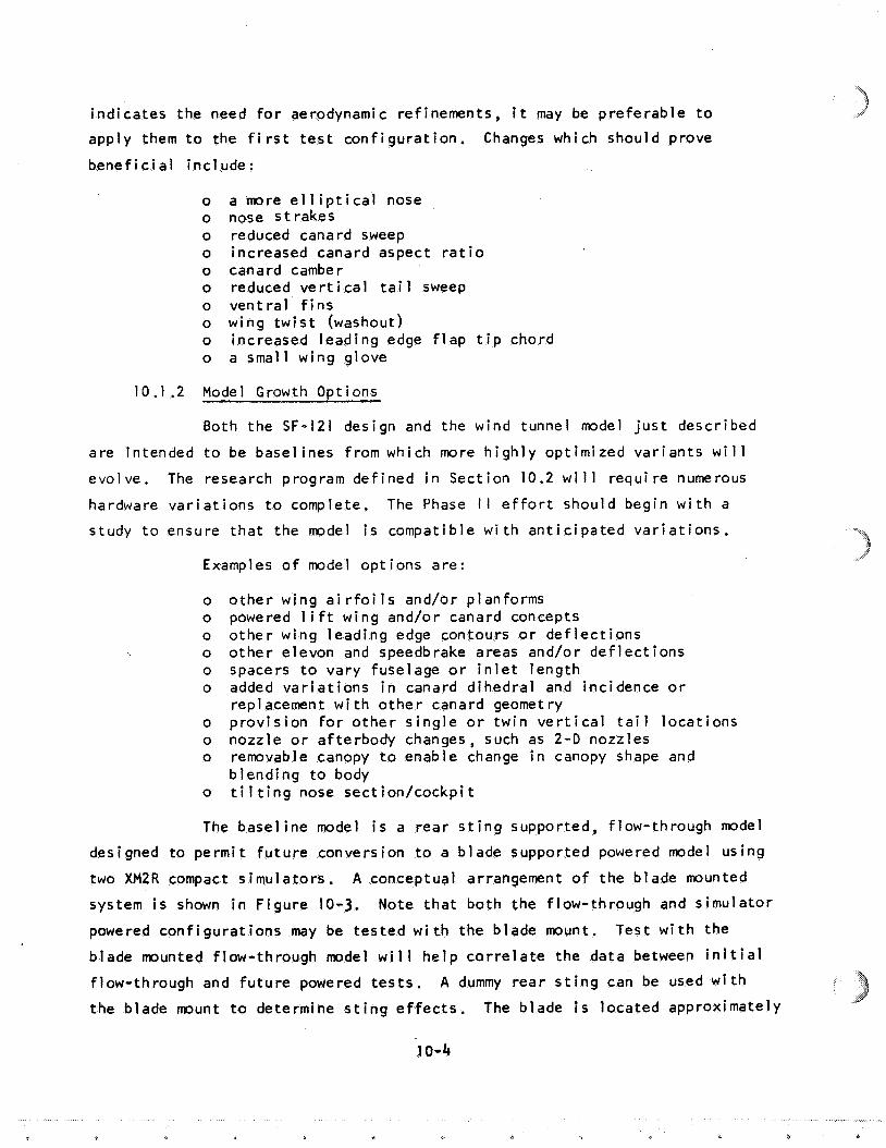
i nd ica tes the need f o r aerodynamic refinements, i t may be p re fe rab le t o
apply them t o the f i r s t t e s t con f igu ra t i on . Changes which should prove
b e n e f i c i a l inc lude:
a more e l 1 i p t i c a l nose nose s t rakes reduced canard sweep increased canard aspect r a t i o canard cambe r reduced v e r t i c a l t a i 1 sweep ven t ra l f i n s wing t w i s t (washout) increased lead ing edge f l a p t i p chord a small wing glove
10.1 .2 Model Growth Options
Both the SF-121 design and the wind tunnel model j u s t described
are intended t o be basel ines from which more h i g h l y op t imized va r ian ts w i l l
evolve. The research program def ined i n Sect ion 10.2 w i 1 1 requ i re numerous
hardware v a r i a t i o n s t o complete. The Phase I I e f f o r t should begin w i t h a
study t o ensure t h a t the model i s compatible w i t h a n t i c i p a t e d v a r i a t i o n s .
Examples o f model op t ions are:
o t h e r wing a i r f o i 1s and/or planforms powered l i f t wing and/or canard concepts o the r wing lead ing edge contours o r d e f l e c t i o n s o the r elevon and speedbrake areas and/or d e f l e c t ions spacers t o vary fuselage o r i n l e t length added v a r i a t i o n s i n canard d ihedra l and incidence o r rep1 acement w i t h o the r canard geometry p r o v i s i o n f o r o t h e r s i n g l e o r tw in v e r t i c a l t a i 1 loca t ions nozzle o r af terbody changes, such as 2-D nozzles removable canopy t o enable change i n canopy shape and b lend ing t o body t i l t i n g nose sec t ion /cockp i t
The base l ine model i s a rear s t i n g supported, f low-through model
designed t o permi t f u tu re conversion t o a blade supported powered model using
two XM2R compact s imula tors . A conceptual arrangement o f the blade mounted
system i s shown i n F igure 10-3. Note t h a t both the f low-through and s imula tor
powered con f igu ra t i ons may be tes ted w i t h the b lade mount. Test w i t h the
blade mounted f low-through model w i l l h e l p c o r r e l a t e the data between i n i t i a l
f low-through and fu ture powered tes ts . A dummy rear s t i n g can be used w i t h
the blade mount t o determine s t i n g e f fec ts . The blade i s located approximately
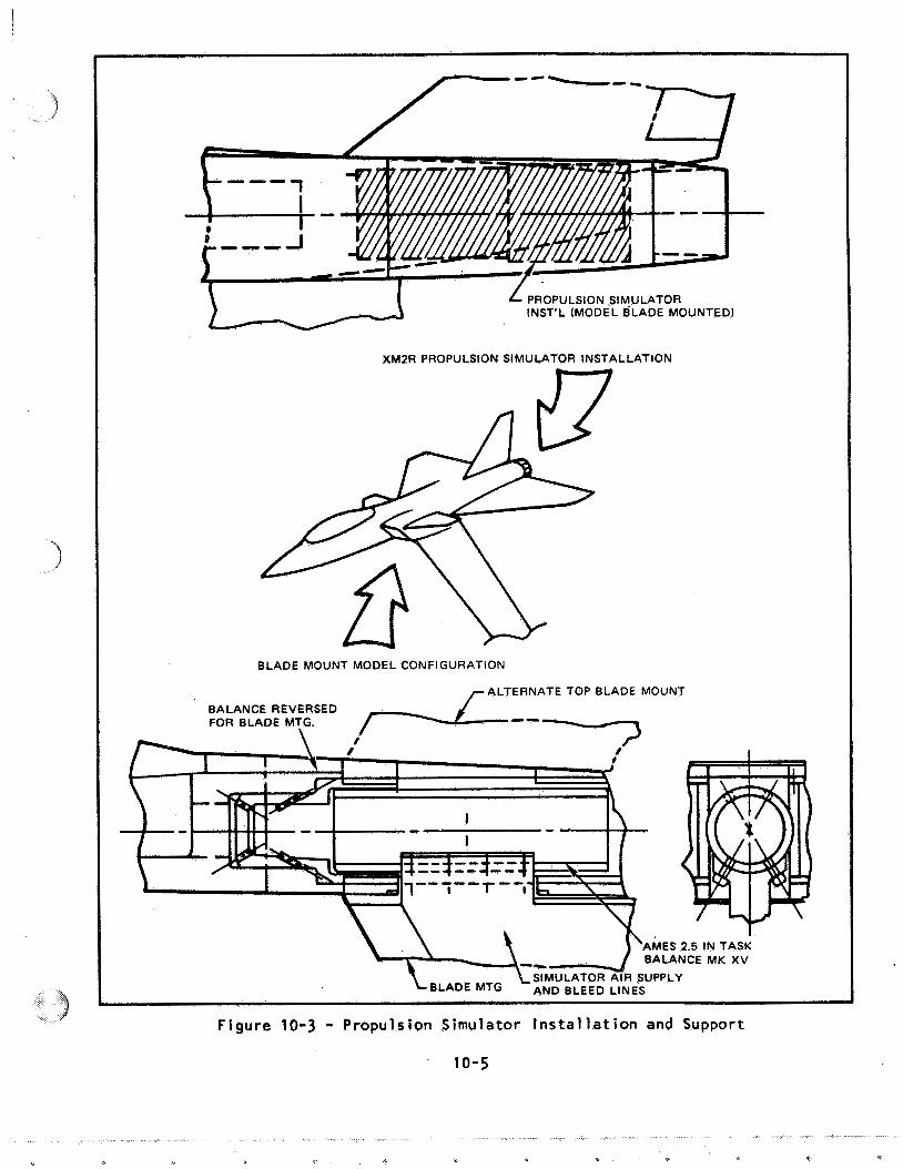
--- PROPULSION SIMULATOR INST'L (MODEL BLADE MOUNTED)
XMZR PROPULSION SIMULATOR INSTALLATION
BLADE MOUNT MODEL CONFIGURATION
ALTERNATETOPBLADE MOUNT
Figure 10-3 - Propulsion Simulator Installation and Support
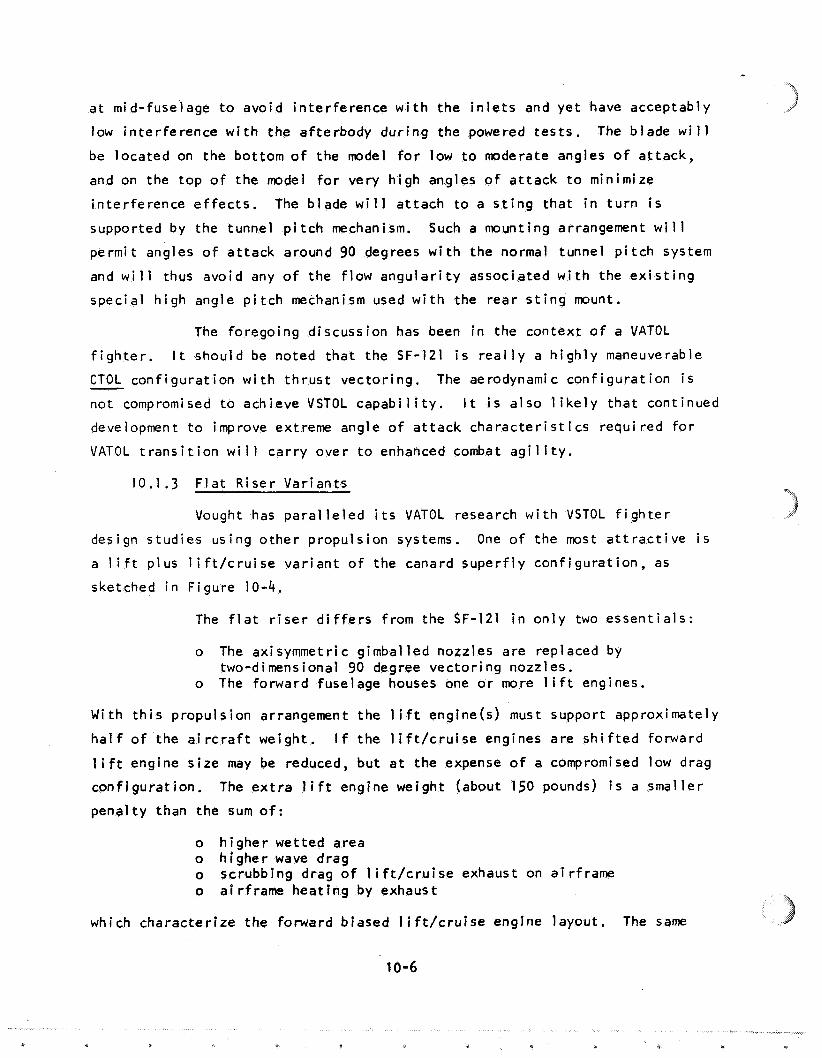
a t mid-fuselage t o avoid i n te r fe rence w i t h the i n l e t s and ye t have acceptably
low in te r fe rence w i t h the af terbody dur ing the powered t e s t s . The b lade w i 1 1
be located on the bottom o f the model f o r low t o moderate angles o f a t tack ,
and on the top o f the model f o r very h igh angles o f a t t a c k t o minimize
in te r fe rence e f f e c t s . The b lade w i l l a t t ach t o a s t i n g t h a t i n t u r n i s
supported by the tunnel p i t c h mechanism. Such a mounting arrangement w i l l
permi t angles o f a t t a c k around 90 degrees w i t h the normal tunnel p i t c h system
and w i l l thus avo id any o f the f low a n g u l a r i t y associated w i t h the e x i s t i n g
specia l h i g h angle p i t c h mechanism used w i t h the rear s t i n g mount.
The foregoing d iscussion has been i n the contex t o f a VATOL
f i g h t e r . I t should be noted tha t the SF-121 i s r e a l l y a h i g h l y maneuverable
CTOL con f igu ra t i on w i t h t h r u s t vec tor ing . The aerodynamic con f igu ra t i on i s - not compromised t o achieve VSTOL c a p a b i l i t y . I t i s a l so 1 i k e l y t h a t cont inued
development t o improve extreme angle o f a t t a c k c h a r a c t e r i s t i c s requi red f o r
VATOL t r a n s i t i o n w i l l ca r ry over t o enhanced combat a g i l i t y .
10.1.3 F l a t R iser Var iants
Vought has para1 l e l e d i t s VATOL research w i t h VSTOL f i g h t e r
design s tud ies us ing o the r propu ls ion systems. One o f the most a t t r a c t i v e i s
a l i f t p lus l i f t / c r u i s e v a r i a n t o f the canard s u p e r f l y con f igu ra t i on , as
sketched i n Figure 10-4.
The f l a t r i s e r d i f f e r s from the SF-121 i n o n l y two essen t ia l s :
o The axisymmetric gimbal l e d nozzles are replaced by two-dimensional 90 degree vec tor ing nozzles.
o The forward fuselage houses one o r more l i f t engines.
With t h i s propu ls ion arrangement the 1 i f t engine(s) must support approximately
h a l f o f the a i r c r a f t weight. I f the 1 i f t / c r u i s e engines are s h i f t e d forward
1 i f t engine s i ze may be reduced, bu t a t the expense o f a compromi sed 1 ow drag
conf igura t ion . The e x t r a l i f t engine weight (about 150 pounds) i s a smal ler
pena l ty than the sum o f :
o h ighe r wet ted area o h ighe r wave drag o scrubbing drag o f 1 i f t / c r u i s e exhaust on a i rframe o a i rframe hea t ing by exhaust
which charac ter ize the forward b iased 1 i f t / c r u i s e englne layout . The same
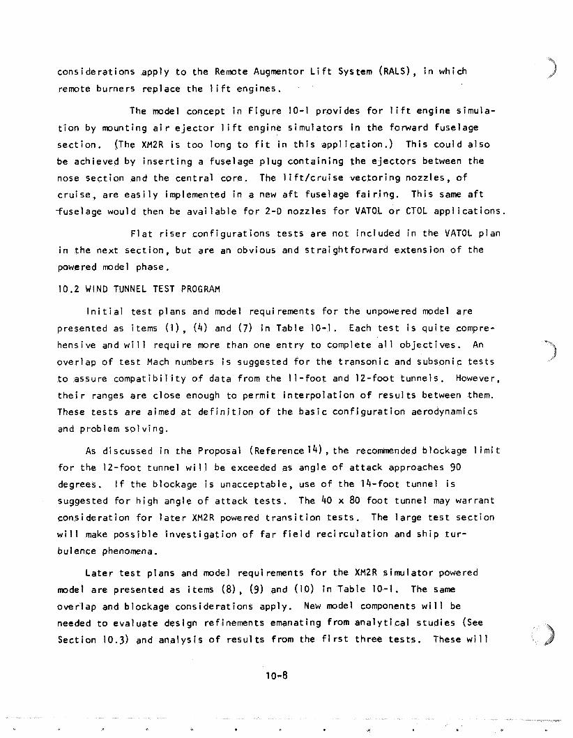
cons idera t ions apply t o the Remote Augmentor L i f t System (RALS) , i n which
remote burners replace the 1 i f t engines.
The model concept i n F igure 10-1 prov ides f o r l i f t engine s imula-
t i o n by mounting a i r e j e c t o r l i f t engine s imu la tors i n the forward fuselage
sec t i on . (The XM2R i s too long t o f i t i n t h i s a p p l i c a t i o n . ) This cou ld a l s o
be achieved by i n s e r t i n g a fuselage p l u g con ta in ing the e j e c t o r s between the
nose sec t i on and the c e n t r a l core. The 1 i f t / c r u i s e v e c t o r i n g nozzles, o f
c r u i s e , are e a s i l y implemented i n a new a f t fuselage f a i r i n g . This same a f t
f use lage would then be a v a i l a b l e f o r 2-0 nozzles f o r VATOL o r CTOL app l i ca t i ons .
F l a t r i s e r con f i gu ra t i ons t e s t s a re n o t inc luded i n the VATOL p lan
i n the next sec t i on , bu t are an obvious and s t r a i g h t f o r w a r d extension o f the
powered model phase.
10.2 W l ND TUNNEL TEST PROGRAM
l n i t i a l t e s t plans and model requi rements f o r the unpowered model a re
presented as i terns (1) , (4) and (7) i n Table 10-1. Each t e s t i s q u i t e compre-
hensive and w i 1 1 requi re more than one e n t r y t o complete a1 1 ob jec t i ves . An
ove r lap o f t e s t Mach numbers i s suggested f o r the t ranson ic and subsonic t e s t s
t o assure c o m p a t i b i l i t y o f data from the 11- foot and 12- foo t tunnels. However,
t h e i r ranges are c lose enough t o permi t i n t e r p o l a t i o n o f resul t s between them.
These t e s t s a re aimed a t d e f i n i t i o n o f the b a s i c c o n f i g u r a t i o n aerodynamics
and problem so l v ing .
As discussed i n the Proposal ( ~ e f e r e n c e l 4 ) , the recommended blockage 1 i m i t
f o r the 12- foot tunnel w i l l be exceeded as angle o f a t t a c k approaches 90
degrees. I f the blockage i s unacceptable, use o f the 14- foot tunnel i s
suggested f o r h i g h angle o f a t t a c k t e s t s . The 40 x 80 f o o t tunnel may warrant
cons idera t ion f o r l a t e r XM2R powered t r a n s i t i o n t e s t s . The l a rge t e s t sec t i on
w i l l make poss ib le i n v e s t i g a t i o n o f f a r f i e l d r e c i r c u l a t i o n and sh ip t u r -
bulence phenomena.
L a t e r t e s t p lans and model requi rements f o r the XM2R s imu la to r powered
model are presented as i tems (8) , (9) and (10) i n Table 10-1. The same
over lap and blockage cons idera t ions apply. New model components w i l l be
needed t o eva lua te design ref inements emanating from a n a l y t i c a l s tud ies (See
Sect ion 10.3) and ana lys i s o f r e s u l t s from the f i r s t t h ree t e s t s . These wi I 1
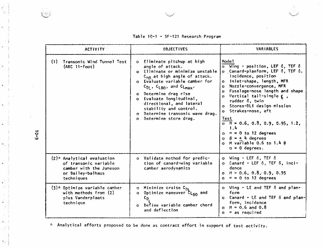
m
W
J
m
a
- P: a z=
a
roc
0
a. "
(D
N
L LL
L
WW
m
C
c
++
cz
u
0
.)
- L
Le
c
.- Ln
Q,
cO
IO
Xk
lO
l
$
41
r: a
LLLL L
Q)
*-
0
WW
CC
-U
-
E
ul
c
Jd
OU
Wm
O,
0)
.-
mu
cc
c
u
cn -
-4
4
c c a
*-
mU
- .
fS
W
CE
.-
~W
--
W
-m
o
03
~1
0 L
In
- I
cm
a a
\D .
.- 0
0
Fa
-.- a, -
- u
a .
m
WU
- a -a m
.- 3
-0
co
LO
W
*-
c
a>
om
-
•
NO
a
V,
(O
an
CC
U
-0
0
.-Q
)Q
)L
LL
J 0-
J .-
c .-
-a
rg
ot
-A
C
U
W
W
U
cO
f
ga
U1
a
cL
OO
I
- 0
na
J
I
-0
-I
I
C u
I c
m I
ma
I
m
\O
ua
mu
\D
u
a- \D
a
IW
I u
-L
L "0
mE
mE
m
C
CU
-N
mL
UO
L
00
0
0
0
0
00
1
.- U C
.- Ln
" 0..
w 0
W
LL W
"Q)
LL
I- C
nf
o
m
. Q
) u
cg
~
w
W
.CV
m
W
>
- U
W
T
m
O
>
F
- >
- 5 a
- "- I
C
Im
C -
m a.
C
a. u
c
u
m
C
m I0
W(
OL
W
C
-
F
UQ
)W
C
U
u
mc
ou
c
a
a
m
WZ
UL
a
- m
n
m
(02
4 0
L
u u
u-
u
I
mm
0
CU
L
- a
.- 3
ua
m
>
L
m C
"L . m
Q
E
*
-a
-
3
U
NU
-Q
X
(O
W0
0
m
.-
ou
m
ac
mt
u~
E
m.--
- E
P
*--a
Q
)J
-U
C
C
U
3
*C
--
U
L3
-U
00
=
A*
- O
n
wc
um
al
V
UE
C~
UU
0-
m
CL
U
rn
m
.-c
u
mo
.-U
L
Lm
x
-C
LW
a
uo
rm
'0
0-
mu
m
m
m>
- --
m
PI
a*-
C
a
cr
aa
U
U-
ut
am
ca
ou
cc
0
m
C, J .-
c, .- .- .- .-
C
Cu
m-
E
mu
-E
E
0-
Q
0-
a 3
L 3 U
.-L
L
E
-
E - -
a-
a
n a
a
.- m
.- a
m A
u m
L
mu
u
-c
- t> 13
a>
-u
aa
U
(P
WU
WU
C
WU
V,C
O
0
0
0
0 0
0 0
U
m
a
I- - Q
) c
c
z 0
cn
.- u
3
0
o
Uc
c
.- I
C .-
0 -
m
c u
m
0: L
a
I--
h
C
Y
I -
u n
-- m
u .-
Q)
L
L
m
CL >
L
mm
O
cU
8.j- .- .-
3 E
u
1m
o
u c
L L
>- U
mu
Q
) c
o
Em
L
U a
a
(0
+J U
- Q
OL
U
Q)
.- c n
- m
.e 5 >
WU
0
c
o
ca
m
0-
Q
) .- n
E
- m m
m
a- 7 m
3
-mQ
)cO
(0
>
XI
>
u
-
au
m
*-
L P
-c
ut
m
m
0.-
re,
~m
3a
3
- -
U
+4 m
L .- .-
2
cp E
u
CU
-m
~a
c
ou
ou
C
h
N
Y
u
L
u
0
c I
m
U
0
m
Q)
d
A
-U
C
V
5 U
Q)
a >
a
m a
-
c
.-a
n
o
3
C
m *-
LID
'-
44
L
U
a
a
> -
UE
m
a
N N
U
- .- .-
0 a)
E
E
.- .- c w
.-
CU
Ju-u
--a
n Q
)c
T
OU
P
cD
0 0
0
L
a
n
E-
m N
U
-
@E
m
-0
u
n1
m
mu
- m
.- - L
ma
m
u
>O
W
LO a
o
uc
=1
N
Q1
Pg
V
.- E
> .- C
.E
=rr
UU
3U
a
*--Q
)
03
au
-1: n
m
Y
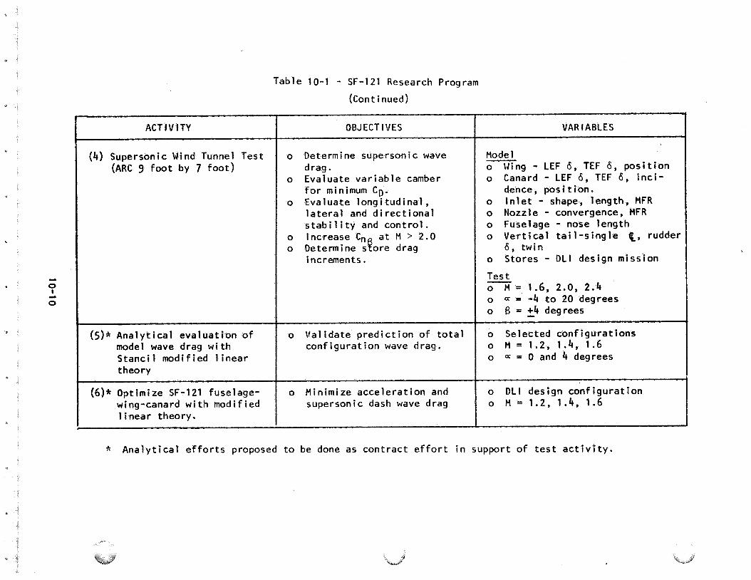
Table 10-1 - SF-121 Research Program
(con t i nued)
* Analy t ica l e f f o r t s proposed t o be done as contract e f f o r t i n support o f t e s t a c t i v i t y .
1
VAR 1 ABLES
Mode 1 o Wing - LEF 6, TEF 6, pos i t i on o Canard - LEF 6, TEF 6, i n c i -
dence, pos i t ion. o I n l e t - shape, length, MFR o Nozzle - convergence, MFR o Fuselage - nose length o Ve r t i ca l t a i l - s i n g l e Q, rudder
6 , tw in o Stores - DL1 design mission
Test - o M = 1.6, 2.0, 2.4 o a = -4 t o 20 degrees o f3 = - +4 degrees
o Selected conf igurat ions o M = 1.2, 1.4, 1.6 o a = 0 and 4 degrees
o DL1 design conf igurat ion o M = 1.2, 1.4, 1.6
ACTIVITY
(4) Supersonic Wind Tunnel Test (ARC 9 f oo t by 7 foo t )
(5 ) * Analy t ica l evaluat ion o f model wave drag w i t h Stanc i l modif ied l i nea r theory
(6)* Optimize SF-121 fuselage- wing-canard w i t h modi f ied 1 i near theory.
OBJECT I V E S
o Determine supersonic wave drag.
o Evaluate va r iab le camber f o r minimum CD.
o Evaluate long i tud ina l , l a t e r a l and d i r ec t i ona l s t a b i l i t y and cont ro l .
o Increase Cn a t M > 2.0 o Determine seore drag
increments.
o Val idate p red ic t ion o f t o t a l conf igurat ion wave drag.
o Minimize accelerat ion and supersonic dash wave drag
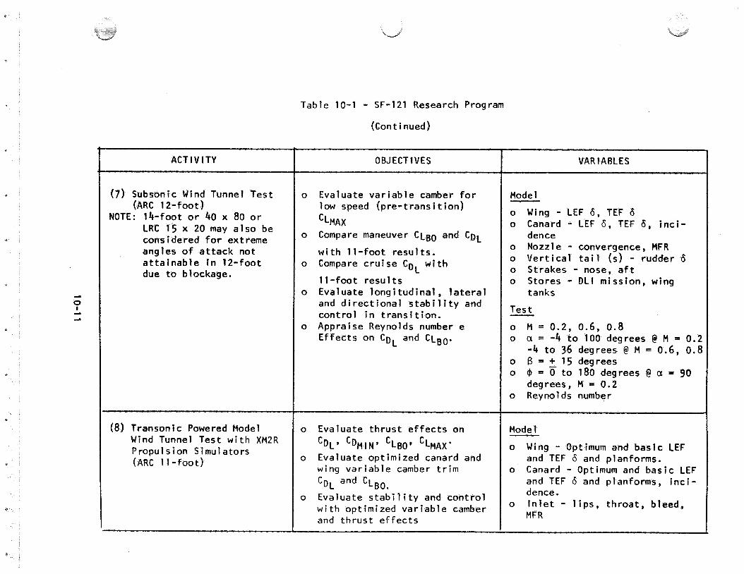
'I
V)
W
A
u2 a
- LL a
>
V)
w
5
- 5 W
7
m
0
cv
a
. . 0
0
0
I
W
Q\
.- H
a
u
m
\O
n c
LT
a,
c
z
- L
U --
0
tS r
u
3
cd,
= a
w
-L
m
II w
al
c
Lo
L
UI
UO
ax
m
a, a,
W
c
U-
0-
L
W
LC
a
,-
mm
W
a m
en
m
m
at
am
mw
a
LU
a
s-
0
00
)O
)a
l *
L
W
al
QE
a,
al
U0
a, a
>--
m
-0
L L
P
WL
C
.-
0-
\
DO
C
nm
O
II E
W
O
mC
d
-.- a
l Q
)a
3
LA
U
U
D
0
UU
-X
C
W
I
0
A1
I
-
I -
W\
O~
O
-m
m
m
cv m
-w
m
u
IU
C
lu
aJ
a
67
+lo
Ez L
a
l-
*-
a
a, m
m
mU
Nw
f0
L.
Y
CC
CN
LL
OC
II
II II
II Cn
>.
*-
ma
l0
P)
uw
m
4
a, a,
~:
uu
z>
v)
~~
ra 1
ms
uc
r
0
00
0
00
0
00
0
0
0
C
d
L
m u
n
LC
0
U
a, m
U
-h
4.J
al
c
u
C
2s
L.
k -2
m
L
.- 01
0
n u
u
-- . n
m
0 . .-
E *-
--- c ~
-f
m
m
mn
0 3
U
ln3
c
m.
-c
u
C
d
U
m
U -
-I
.-
ow
u
a, L
3 0
u m
a-
mc
-
u
L. m
u
3
mu
m
n
L a,
mw
-
c-
.!!
t! 3
am
0 -I
LP
a,
we
- 3 c o
us
u
mu
c
03
m
o.
-
a, >
m
0
1
al
cw
c~
c
u
E
y:,u
L
U.-
0
a, a,
ma
,
al U
a,
2
.--a
WW
L-
am
PL.
om
.-
0.
-w
m
P
=a
xm
m
0
3u
~m
u
- a
ar
ar
c-
u
~a
,
m3
r E
WE
I
(P
UC
PU
-
>o
-f
0
-0
-
->
co
nr
e
W-
0
0
3u
PW
mu
aw
0
0
0
0
0
LL
I
W .-
LL A
U -
W
-I
C) .- c
u
.- al
0
am
- al
.--V
,(D
V,
.n ;E
nE
a
no
uo
w
U
-C
u-
m
u
cm
c
cm
m
?
0=
1a
u
m-
E-
r
E
EC
WS
a
5u
.-u
- a
n
U
0
.- P
W
w
C
0
I
LL
Ll
I W
WW
. i-
Ll-
a,
w
~J
I C
U m
C
U u
u
C-C
L
0
0
- L
u
c
0
a, 1
9
c
m
w E
c
m
0
U
O.
0L
.E
C
) m
x
mL
.
a, u
a
cw
0
-
u
~:
m
c n
Q
1-
I U
L
U- U
aJ
.- m
m
u- u
n
>.L
m
-
WE
w
mw
* g.3
J='S
m
-f
E
-- u U
- 3
U
*- 0)
.n
0
%
L
w-
O
fD
Ne
,
r -
an
m
u.-
-
ZO
fU
-I
WE
*
- .-
.- ul
a, r
a,
~ a
u3
u n
-
mu
u QL
mu
3
m>
r
m0
5
3
m3
--.--In
,-=
m
-
fm
r
-~
mw
u
> n
>.-
n
>.-
c
wu
W3
0 w
3
m
0
0
0
>- I- - >
- t v a
w
a, a
P
al @
LE
U
I- O
Oa
l~
G
m~
oo
-
0.-
UC
U-
a,
am
x I
C
QY
N.
c
X>
U
-a
,
3
mL
m
m
OE
Ow
Cm
)-
a
U-U
-Y
O
h 0
m
u
CU
Lc
vU
a
0
9-
00
o
re
--
'2
x ; o
+n
U
I
mo
mc
o
.-cv
8-.-
a,.- w
C
-U
-
m-
m
10
cm
wa
J
2U
aP
ZO
cw
3
a=
-.--
C)
m m
u
3 a
V) w
.. W
- I-
- 0
- Z
CS
C
V r
- X
a, u
r a
O
UL
r.- 0
u3
:
a,-
-
L
m 3
Q
al
E
gt--- V)
w
0,-
0
wc
o
0 c
0:
.- c .-
c 3 a
-
$'--
3
c u
nu
m
c
O&
L
.- ~a
t 3
aw
n
03
w
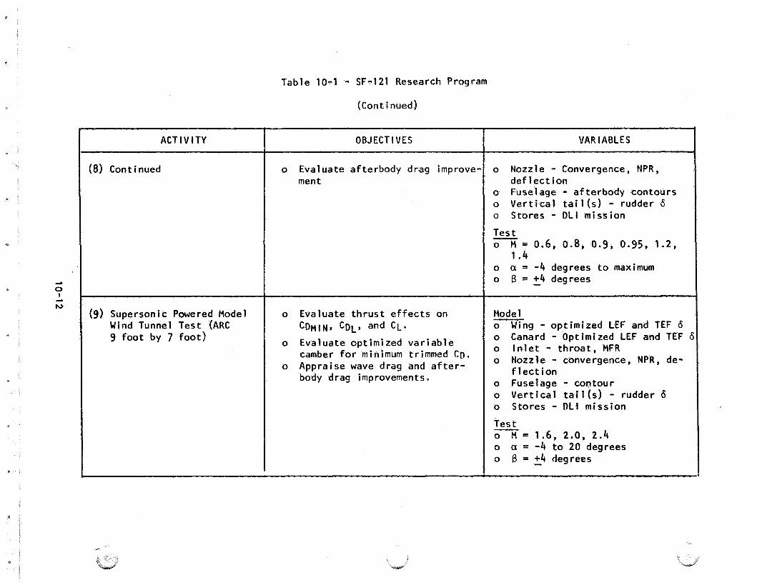
Table 10-1 - SF~121 Research Program
(Cont i nued)
'1
r ACTlV ITY
(8) Con t i nued
(9) Supersonic Powered Model Wind Tunnel Test (ARC 9 foo t by 7 foot )
OBJECT1 V E S
o Evaluate afterbody drag improve- men t
o Evaluate th rus t e f f ec t s on CDHIN, C D ~ , and CL.
o Evaluate optimized var iab le camber fo r minimum trimmed CD.
o Appraise wave drag and a f t e r - body drag improvements.
VARIABLES
o Nozzle - Convergence, tlPR, de f l ec t i on
o Fuselage - afterbody contours o Ve r t i ca l t a i l ( s ) - rudder 6 o Stores - DL1 mission
Test - o M = 0.6, 0.8, 0.9, 0.95, 1 . 2 ,
1.4 o a = -4 degrees t o maximum o B = +4 degrees
- Mode 1 o Wing - optimized LEF and TEF 6 o Canard - Optimized LEF and TEF 6 o I n l e t - throat , MFR o Nozzle - convergence, NPR, de-
f l e c t ion o Fuselage - contour o Ve r t i ca l t a i l ( s ) - rudder 6 o Stores - DL1 mission
Test - o M = 1.6, 2.0, 2.4 o a = -4 t o 20 degrees o B = - +4 degrees
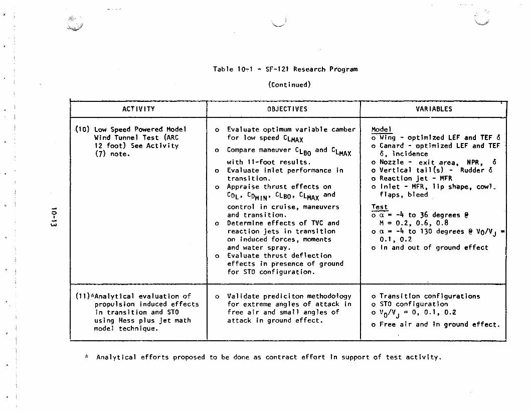
Table 10-1 - SF-121 Research Program
(con t i nued)
U n a l y t i c a l e f f o r t s proposed t o be done as contract e f f o r t i n support o f t e s t a c t i v i t y .
OBJECT l VES VAR l ABLES
- o Wing - optlmlzed LEF and TEF 6
o Compare maneuver C L ~ ~ and CLHAX o Canard - optimized LEF and TEF
w i t h 11-foot resu l t s . o Nozzle - e x i t area, NPR, 6 o Evaluate i n l e t performance i n o Ve r t i ca l t a i l ( s ) - Rudder 6
t rans i t i on . o Reaction j e t - HFR o Appraise th rus t e f f ec t s on o I n l e t - HFR, l i p shape, c w l ,
(1 t ) * ~ n a l y t i c a l evaluat ion o f propuls ion induced e f f ec t s i n t r a n s i t i o n and ST0 using Hess plus j e t math
I model technique. I I o Free a i r and i n ground e f f ec t . I
CDL, C D ~ ~ ~ , CLBO, CLHAX and
cont ro l i n cruise, maneuvers and t r ans i t i on .
o Determine e f f ec t s o f TVC and react ion j e t s i n t r a n s i t i o n on induced forces, moments and water spray.
o Evaluate t h rus t de f l ec t i on e f f ec t s i n presence o f ground f o r ST0 conf igurat ion.
o Val idate p red ic i ton methodology f o r extreme angles o f a t tack i n f r ee a i r and small angles o f a t tack i n ground e f f ec t .
f laps, bleed
Test - o a = -4 t o 36 degrees @
M = 0.2, 0.6, 0.8 o a = -4 t o 130 degrees @ V0/VJ =
0.1, 0.2 o I n and out o f ground e f f e c t
o T rans i t i on conf igurat ions o ST0 conf igurat ion o Vo/VJ = 0, 0.1, 0.2
inc lude lead ing and t r a i l i n g edge f l a p s , s t rakes and ex te rna l f a i r i n g s . Ro l l I
reac t ion j e t s w i l l a l s o be simulated. T h e i r a i r supply w i l l be routed through
the lead ing o r t r a i l i n g edge f l a p a t tach s ta t i ons . This model design
approach w i l l a l s o f a c i l i t a t e t e s t s o f lead ing and t r a i l i n g edge boundary
l a y e r c o n t r o l . The main wing beam w i l l be designed t o a l l o w maximu!:, f l e x i -
b i l i t y f o r lead ing and t r a i l i n g edge f l a p v a r i a t i o n s . These t e s t s w i l l a l so
assess d i r e c t t h r u s t and j e t induced e f f e c t s .
10.3 METHODS DEVELOPMENT
While the Phase I I contracted e f f o r t i s concerned e x c l u s i v e l y w i t h design
and f a b r i c a t i o n o f the basel i ne wind tunnel model , a discussion o f appropr iate
p a r a l l e l i n g research i s i n order . Vought has been a c t i v e i n a n a l y t i c a l aero-
dynami cs and ae ropropul s ion methods development . Three cur rent programs
re levant t o SF-121 con f igu ra t i on research wi 1 1 be described i n the f o l lowing
paragraphs.
10.3.1 Supersonic Modi f ied L inear Theory - Recent se rv i ce design s tud ies (USAF ATF and USN NFA) have
st ressed the need f o r design o f e f f i c i e n t supersonic c r u i s e and dash a i r c r a f t .
Se lec t ion o f the "best" con f igu ra t i on dur ing p r e l iminary design o f a new
m i 1 i t a r y a i r c r a f t o r m i s s i l e depends more on the accuracy o f p red ic ted t rend,
o r incremental, data than on the absolute accuracy o f the data. Current wave
drzg p r e d i c t i o n techniques are based p r i m a r i l y on the supersonic area r u l e .
The slender body assumption inherent i n the area r u l e i s o f t e n v i o l a t e d i n
one o r more l o c a l areas on a f i g h t e r o r m i s s i l e con f igu ra t i on ; w h i l e o v e r a l l
drag p r e d i c t i o n may s t i l l be f a i r l y accurate, incremental p red ic t i ons are
o f t e n unrel i ab le . Improved a n a l y t i c a l methods are needed f o r moderate t o low
f ineness r a t i o n con f igu ra t i ons t y p i c a l o f f i g h t e r s and m iss i l es .
S i m i l a r l y , a1 1 present methods o f ana lyz ing o r designing super-
son ic camber and o f ana lyz ing supersonic drag due t o 1 i f t e f f e c t s u t i l i z e
1 i nea r i zed theory. The small p e r t u r b a t i o n assumption o f 1 inear ized theory i s
severely v i o l a t e d near the lead ing edge o f conventional a i r f o i 1s (rounded
leading edges). The lead ing edge i s a l s o where the pr imary e f f e c t s o f camber
o r i g i n a t e . Pred ic ted and measured supersonic camber e f f e c t s o f t e n disagree
when the wing has a rounded lead ing edge, o r when wing-body in te r fe rence
e f f e c t s are s i g n i f i c a n t . Thus, i n o rde r t o a1 low r a t i o n a l design o f m i s s i l e
o r f i g h t e r which cruises o r maneuvers supersonical ly , a h igher order ana ly t i ca l
method i s needed f o r supersonic camber and tw i s t design and f o r supersonic drag I
due t o l i f t evaluat ion.
Vought has completed f e a s i b i l i t y studies t ha t show that near f i e l d
so lu t ions t o obta in accurate (nonl inear) pressure d i s t r i bu t i ons need not re-
qu i re exorb i tant computer time o r core. These studies used modi f ied l i nea r
theory and s i g n i f i c a n t l y improved the accuracy o f p red ic t ion o f wave drag due
t o thickness f o r wings, cones and axisymmetric bodies. The method i s not
inherent ly r e s t r i c t e d t o p lanar o r axisymmetric surfaces, but as yet i t has not
been programmed f o r more general shapes. The f a c t t ha t a u n i f i e d method has
provided accuracy comparable t o Van Dyke's second order theory f o r the va r ie ty
o f shapes f o r which i t has been programmed leads t o the conclusion that i t
should work equal ly we1 1 fo r general 3-dimensional shapes. Therefore, the
modif ied 1 inear theory method w i 1 1 be programmed t o a1 low ca lcu la t ions o f
loca l ' f low condi t ions, pressures and in tegrated 1 i f t , pressure drag, and
p i t ch i ng moment on complete conf igurat ions and on wings w i t h camber, t w i s t
and thickness. -\
1 4) The method has been developed t o date under Vought's Independent
Research and Development Program, and was i n i t i a l l y reported i n Reference 5.
The ob jec t i ve o f t h i s p ro j ec t i s t o improve the capab i l i t y t o design f i g h t e r
a i r c r a f t and miss i les having low supersonic drag. This w i l l be accompl ished
by developing higher order analysis and design rout ines and subs t i t u t i ng
them f o r the 1 inear theory modules i n the NASA/Middleton integrated super-
sonic design and analysis system. This ob jec t i ve can be d iv ided i n t o two
par ts . Part I involves the accurate p red ic t ion o f z e r o - l i f t wave drag, and
Part I I includes p red ic t ion o f supersonic drag due t o 1 i f t and camber drag,
thickness and camber in te rac t ions , and methods f o r designing optimum cambered
surfaces.
Work on Part I was begun on March 13, 1978 under j o i n t Navy/NASA
sponsorship as proposed i n Reference I S . This n ine month e f f o r t w i 1 1 provide
a computer program capable o f ca l cu la t i ng supersonic f low condi t ions over a
s ing le , n o n - a x i s y m t r i c body such as a fuselage w i t h canopy. Successful
completion o f t h i s program would provide a basis f o r a follow-on program t o
extend the computational capabi 1 i t y t o complete conf igurat ions.
Future work on Par t I I w i 1 1 invo lve the same bas ic techniques as
i n Par t I w i t h mod i f i ca t i ons as required f o r l i f t i n g ana lys is . These m o d i f i -
ca t ions would invo lve d i v i d i n g the f lows above and below the 1 i f t i n g sur face
(wing) i n t o separate regions using a diaphragm technique, o r adding doublet
o r vor tex panels t o the source panels used i n the Par t I procedure. Completion
o f these tasks i s expected i n 18-24 months i f s u f f i c i e n t funding becomes
ava i l ab le .
10.3.2 Transonic Wing Opt imiza t ion
Maneuverabi l i ty a t M = 0.6 and subsonic c r u i s e are SF-121 design
fac to rs which can be improved by t ranson ic wing op t im iza t i on . Vought Corpora-
t i o n and NASA Ames Research Center began a cooperat ive e f f o r t i n 1973 t o apply
p red ic t i ons w i t h experiment. I t was hoped tha t t h i s work would e s t a b l i s h
guide1 ines f o r computational wing design and a l so i d e n t i f y areas where improve-
ment was needed i n the ana lys is codes. I n 1975 Vought and NASA Ames began a
j o i n t e f f o r t t o develop wing op t im iza t i on procedures and t o v e r i f y them
experimental l y . Camber d i s t r i b u t i o n s f o r Vought's va r iab le camber semi -span
wing model were def ined using a t ranson ic ana lys is code combined w i t h an
op t im iza t i on procedure. The designs were tes ted i n the NASA Ames 14 f o o t
t ranson ic tunnel and compared against r e s u l t s from previous design s tud ies on
the wing. With the f e a s i b i l i t y o f the approach now es tab l ished, the procedures
are being extended t o encompass a r b i t r a r y wing planforms.
A three dimensional a n a l y t i c a l design procedure was formulated by
u t i l i z i n g p o t e n t i a l f low wing ana lys is techniques and numerical op t im iza t i on
w i t h i n the geometr ic cons t ra in ts o f a v a r i a b l e camber wing. The Bai ley-Bal lhaus
t ranson ic p o t e n t i a l f low ( ~ e f e r e n c e 16) and Woodward-Carmichael l i nea r
p o t e n t i a l f low ana lys i s (Reference 18) codes were l i n k e d t o Vanderplaat 's
constra ined min imiza t ion rou t ine (Reference 19) through a geometry module.
The f l a p hinge l i n e s and angle o f a t t a c k were used as decis ion va r iab le i n the
op t im iza t i on rou t ine t o de f ine the camber and t w i s t d i s t r i b u t i o n s t o minimize
drag f o r the wing. The ac tua l o p t i m i z a t i o n procedure cons is ts o f pe r tuba t ing
each o f the dec is ion va r iab les independently t o determine gradients. The
d i r e c t i o n and r e l a t i v e d e f l e c t i o n magnitudes t o change the decis ion var iab les
are then computed from the gradients. The c o n t r o l l i n g module o f CONMIN then
changes the dec is ion var iab les simultaneously u n t i l e i t h e r the drag increases
o r a const ra in t i s encountered. A new set o f gradients, along w i t h a new move
d i r ec t i on , i s then computed. I f a const ra in t has been reached a new d i r ec t i on ! i s selected i n an attempt t o fu r the r reduce drag wi thout v i o l a t i n g the con- i
s t r a i n t . Physical l i m i t s o f the f l a p def lec t ions plus a maximum p i t ch i ng
moment l i m i t were the const ra in ts imposed on the design conf igurat ions. The
p i t ch i ng moment cons t ra in t was imposed on the design space t o r e s t r i c t the
t r i m drag penal ty incurred w i t h an t i c ipa ted a f t wing loading. When the con-
f i g u r a t i o n drag could not be reduced f u r t he r wi thout v i o l a t i n g a cons t ra in t ,
the optimum camber d i s t r i b u t i o n has been found. S t r i p theory incorporat ing
viscous e f f ec t s would have t o be included f o r analysis o f the M = 0.6 maneuver
condi t ion. This i s cu r ren t l y being developed under contract t o AFFDL. A
more comprehensive discussion o f the methods employed and comparisons w i t h
t es t data i s i n preparation.
10.3.3 Propulsion Induced E f fec ts
Propulsion induced e f f ec t s a t angles o f a t tack exceeding s t a l l
are present ly not ca lcu lab le . Separated flows from the s t a l l e d a i r c r a f t
i nva l ida te estimates o f near f i e l d ve loc i t i es a t o r near the j e t e x i t .
1 However, i f separated flows are l i m i t e d t o upper surfaces, freestream ve loc i -
t i e s may be used t o est imate j e t induced e f fec ts . Review o f t e s t resu l t s
would be needed t o determine the relevant f low propert ies. Comparison o f
j e t - o f f vs. jet -on t e s t resul t s woul d permit val i da t ion o r development o f
methodology f o r p red i c t i ng h igh angle o f a t tack j e t induced e f fec ts .
Vought has been working t o develop p red i c t i on methods f o r pro-
pu ls ion induced e f f ec t s since 1975. The approach has been t o superimpose j e t
e f f e c t s v i a j e t math models onto an a i r c r a f t f low f i e l d . Hess' po ten t ia l flow
aerodynamic analysis computer rout ine i s the cornerstone o f Voughtls act i v i t y
(Reference 20). Jet math models used o r t o be used include those by Wooler
(~e fe rence 21). Weston and Dletz (Reference 22 and 23) , and Thames (~e fe rence 24).
The l a t t e r model i s being developed f o r an NADC contract a t NASA/LRC. I t i s
being done t o determine math models f o r rectangular j e t s . Vought i s a lso
cu r ren t l y working under contract t o NADC t o develop a computerized p red ic t ion
method f o r propuls ive lnduced forces and moments i n t r a n s i t i o n and short take-
o f f f 1 i gh t (~e fe rence 25). The method i s based on the Vought V/STOL A i r c r a f t - - Propulsive E f fec ts computer program (VAPE) . VAPE cu r ren t l y ca lcu la tes - -
propu ls i ve induced e f f e c t s i n t he t r a n s i t i o n region a t low t o moderate angles
o f a t t a c k and i n a l i m i t e d p o r t i o n o f the ST0 region. Th is e f f o r t i s concen-
t ra ted upon improving the e x i s t i n g c a l c u l a t i o n techniques and adding new
methods.
New methods are p r i m a r i l y aimed a t i nco rpo ra t i ng improved j e t
modeling techniques i n t o V A P E . F i r s t , m u l t i p l e j e t mod i f i ca t ions t o Weston's
model ( ~ e f e r e n c e 23)wi 1 1 be f i n i shed . Th i s w i 1 1 inc lude techniques f o r merged
j e t s and methods t o account f o r p a r t i a l l y b locked j e t s . Then, the j e t model
w i 1 1 be modi f i e d t o account f o r wake e f f e c t s behind the j e t s . F i n a l l y , rec-
tangu lar j e t math models be ing developed under con t rac t ( ~ e f e r e n c e 24) w i l l be
i n teg ra ted i n t o VAPE. The rec tangu lar j e t math models developed a l s o inc lude
co- f low ing and smal l d e f l e c t i o n cases which may be appl i e d f o r ana lys i s o f
h i gh subson i c maneuver ae rodynami cs . I t should be noted t h a t the a n a l y t i c a l techniques descr ibed
above are app l i cab le t o a wide range o f con f i gu ra t i ons . C o r r e l a t i o n o r
v a l i d a t i o n w i t h any t e s t c o n f i g u r a t i o n would o f f e r i n s i g h t i n t o t h i s realm o f
computational aerodynamics. Special a t t e n t i o n would be needed t o cover the
h i g h angles o f a t t a c k experienced by a VATOL a i r c r a f t . VAPE w i l l p rov ide a
broad based a n a l y t i c a l c a p a b i l i t y .
11.0 CONCLUSIONS
Comparative propuls ion concept studies by Vought (Reference 1) show
the Ver t i ca l A t t i t ude Takeoff and Landing (VATOL) t o be super ior i n
performance t o the a l te rna t i ves .
The SF-121 conceptual design meets o r exceeds a l l ob jec t i ve per-
formance guide1 ines.
The VATOL concept exh ib i t s exce l len t short takeo f f performance.
Ve r t i ca l a t t i t u d e t r a n s i t i o n t o hover i s feas ib le w i t h one engine
disabled.
Aerodynamic estimates ind ica te the base1 ine conf igurat ion i s
d i rec t iona l l y unstable i n the pos t - s ta l l regime.
With proper react ion cont ro l phasing the ind icated d i rec t iona l
s t a b i l i t y can be to le ra ted during t r ans i t i on .
Su f f i c i en t th rus t from one engine should be avai l ab le t o achieve
MIL -F-83300 Leve 1 2 combined con t r o l response i n hover.
P r inc ipa l aerodynamic uncer ta in t ies are:
o Low speed pos t - s ta l l aerodynamics
o Control power around 50 degrees angle o f at tack
o Bu f fe t charac te r i s t i cs i n VATOL t r a n s i t i o n and i n t ransonic
maneuvering f l i g h t
o Effect iveness o f h igh speed th rus t vector ing
o Close coupled canard aerodynamics i n the t ransonic/
superson i c regimes
o I n l e t d i s t o r t i o n a t large angles o f a t tack and s ides l ip .
Other uncer ta in t ies about VATOL mode operat ions are:
o E f fec ts o f sh ip wake turbulence
o Propuls ion induced spray
o P i l o t v i s i b i l i t y requirements.
The aerodynamic uncer ta in t ies can be resolved by a cornprehens i ve wind
tunnel t es t program complemented by ana l y t i ca l methods development
p rog ram.
The XM2R compact propulsion s imulator should be a valuable adjunct t o
both h igh speed and VATOL t r a n s i t i o n regime wind tunnel tes ts .
The proposed Phase I I wind tunnel model can prov i de a qua1 i t y data
base and i s compatible w i t h many growth options.
o The model can eas i ly be configured t o represent VATOL o r f l a t r i s e r
propulsion concepts.
o The study configuration i s essential l y uncornprornised fo r VSTOL and
i s representat i ve o f advanced CTOL f ighters .
12.0 REFERENCES
Dr iggers, H. H.: S e n s i t i v i t y Studies f o r Several High Performance VSTOL Concepts. Paper No. 770982 presented a t SAE Aerospace Engineering and Manufactur ing Meeting, Los Angeles, November 14-1 7, 1977.
Abbott , R . A. : Request f o r Proposal - Study o f Aerodynami c Technology f o r VSTOL F i gh ter /A t tack Ai r c r a f t. RFP2-26710, NASA-Ames Research Center, 15 June 1977.
Box, D. M.: Vought High Speed Wing Tunnel S t a t i c Force Tests on a 0.05 Scale V/STOL Type B F i g h t e r i n the Mach Range o f 0.6 t o 2.4. Vought Corporat i on Report No. 2-53710/6R-51389. ( H S ~ T Tests 588 and 595, September & Novembe r , 1976.
Gloss, 8. B. : E f f e c t o f Canard Locat ion and Size on Canard-Wing I n t e r - ference and Aerodynami c-Center Shi f t Related t o Maneuvering A i r c r a f t a t Transon i c Speeds. NASA TN D-7505, June 1974.
Stanci l , R. T. : Improved Wave Drag Pred ic t ions Using Modi f ied L inear Theory, Al AA 3rd Atmospheric F l i g h t Mechanics Conference, A r l ington, Texas, June 1976.
Capone, F. J.: E f f e c t s o f Nozzle E x i t Locat ion and Shape on Propuls ion- Induced Aerodynamic Charac te r i s t i cs Due t o Vector ing Twin Nozzles a t Mach Numbers f rom 0.40 t o 1.2. NASA TM X-3313, January 1976.
Linden, J . E. and O'Brimski, F. J.: Some Procedures f o r Use i n Per for - mance Pred ic t ion o f Proposed A i r c r a f t Designs. SAE Paper 650800, October 1965.
Arnold, J. W . : Transonic S t a t i c S t a b i l i t y Tests on a .oh58 Scale V-1100 Model i n the VAC High Speed Wind Tunnel. Vought Corporat ion Report No. 2-59710/1 R-2954, September 1971. (HSW Test 416)
USAF S t a b i l i t y and Control DATCOM. Douglas A i r c r a f t Co., Contract No. AF-33 (61 5) -1609 and (616) -6460, October 1960, Revised under Contract ~33615-754-3067, Apr i l 1976. '
I n v e s t i g a t i o n o f Non-Axisymnet r i c Nozzles I n s t a l l e d i n Tac t i ca l Ai r c r a f t , Volume I - Study Results, Technical Report AFFDL-TR-75-61 , Vol . 1 , June 1975.
Dr iggers, H. H. : SF-122 VSTOL S t r i k e F i g h t e r Concept and Performance. Vought Corporat ion Report No. 2-38100/8~-51534, 31 March 1978.
G i rard, P. F., and Evere t t , W. L.: A Test P i l o t Report on the X - 1 3 Vert i j e t and VZ -3RY Ver t i p l ane. Anna1 s o f the New York Academy o f Sciences, V.107, A r t i c l e 1, March 25, 1963.
G i rard, P. F. : P i l o t i n g Procedures and Some Human Factors Aspects o f the VTOL - T r a n s i t i o n Cycle o f t he X-13 A i r c r a f t , iAS 27th Annual Meeting, New York, N. Y , , January 26-29, 1959.
Study o f Aerodynamic Technology f o r V e r t i c a l Short Takeoff and Landing (VSTOL) F i gh ter /A t tack A i r c r a f t - Technical Proposal . Vought Corporat ion Advanced Techno1 ogy Center Report No. 2-381 00/7P-26, 22 J u l y 1977.
S t a n c i l , R. T.: Development o f an Improved Wave Drag P r e d i c t i o n Method Techn i ca l Proposal . Vought Corporat ion Report 2-37100/7~-3426, 19 September 1977.
Bal lhaus, W . F., and B a i l e y , F. R.: Numerical C a l c u l a t i o n o f Transonic Flow About Swept Wings. AlAA Paper 72-677, June 1972.
Jameson, A . , e t a1 : A B r i e f Desc r ip t i on o f the Jameson-Caughey NYU Transonic Swept-Wing Computer Program - FLO 22. NASA TM X-73996, Decembe r 1976.
Woodward, F. A.: A U n i f i e d Approach t o the Ana lys is and Design o f Wing-Body Combinations a t Subsonic and Supersonic Speeds. A l AA Paper 68-55, January 22, 1968.
Vanderplaats, G. N.: CONlYlN - A FORTRAN Program f o r Constrained Funct ion Min imiza t ion User 's Manual. NASA TM X-62282, August 1973.
Hess, J. L.: C a l c u l a t i o n o f P o t e n t i a l Flow About A r b i t r a r y Three- D i men,ional L i f t i n g Bodies. Doug1 as Report MBC ~5679-01 , October 1972.
Wooler, P. T., e t a1 : V/STOL A i r c r a f t Aerodynamic P r e d i c t i o n Methods I n v e s t i g a t i o n . A F F D L - T R - ~ ~ - ~ ~ , Vol . 1 , January 1972.
D i e t z , W i 1 1 iam E. , J r . : A Method f o r C a l c u l a t i n g the lnduced Pressure D i s t r i b u t i o n Associated w i t h a Je t i n a Crossf low, Masters Thesis, U n i v e r s i t y o f F l o r i d a , 1975.
Weston, Robert P.: The Contra-Rotat ing Vor t i ces Associated w i t h a Je t i n a Crossf low, Masters Thesis, U n i v e r s i t y o f F l o r i d a , 1974.
Thames, F. C. : Development o f an A n a l y t i c a l Model f o r Rectangular J e t Flows I ssu ing i n t o a Crosswind. Vought Technical Proposal No. 2-57110/ 6R-3279, March 1976.
Beat ty , T. D.: Development o f a P r e d i c t i o n Methodology f o r Propu ls ive Induced Forces and Moments i n Transit ion/STO F l i g h t . Vought Technical Proposal No. 2-37100/7R-3416, J u l y 1977.