Study on MU-MIMO feature in 802.11ac using · PDF fileStudy on MU-MIMO feature in 802.11ac...
14
Study on MU-MIMO feature in 802.11ac using MATLAB NS Ravindranath #1 , Inder Singh #2 , Ajay Prasad #3 , V. Sambasiva Rao *4 # University of Petroleum and Energy Studied, Bidholi Campus, Dehra Dun, Uttarakhand, India 1 [email protected] 2 [email protected] 3 [email protected] * PES University, Banashankari 3rd stage, Bangalore, Karnataka, India 4 [email protected] Abstract— Multi-user Multiple-Input-Multiple-Output is a technique of MIMO technology added to 802.11ac WLANs which is expected to be the major innovative feature in improving performance. Objectives are to simulate basic scenarios to get an understanding of MU-MIMO and to identify functional blocks in the MAC/PHY layers to which modifications are made to support MU-MIMO. In this paper, MU-MIMO is studied extensively by examining the modifications which have been made to different functional blocks of both MAC and PHY layers to support MU MIMO. MATLAB R2016a version has incorporated a WLAN System Toolbox with provision to design, configure the physical layer in IEEE 802.11ac WLAN standard. Hence, simulations of some scenarios are performed in MATLAB. The MU-MIMO feature in 802.11ac introduces multiple spatial streams distributed between the clients. Multiple clients can be serviced simultaneously, hence congestion delay is not an issue. MU MIMO helps in distributing data to 4 users simultaneously using the space streams obtained through smart antennas. This is a major improvement over the limitation imposed by the MAC algorithm used in WLANs where stations can only gain access one following the other. Hence, latency and also throughput can be increased for multimedia applications. The following functional blocks have been identified to be key in MU MIMO performance. Sounding, Precoding and detection techniques in the PHY layer and Aggregation , TXOP and back off mechanisms in the MAC layer. These areas would then be the points of interest to future researchers who wish to enhance MU MIMO performance. Research is proposed in PHY(Algorithmic improvements in Precoding and detection) and in MAC - Design a scheduler to optimise aggregation and TXOP/back off mechanisms to improve QoS for multiple users. Keyword - 802.11ac, MU MIMO, Aggregation, Precoding, Access Point, QoS, TXOP I. INTRODUCTION Multi-user Multiple-Input-Multiple-Output (MU-MIMO)is a feature introduced with 802.11ac Wave 2 and it differs from Wave 1 which had single-user MIMO (SU-MIMO). With MU-MIMO more than one client receive packets at the same time from the Access Point (AP) leading to frequency reuse of the available spectrum and hence better system performance. With 802.11n [1][2], all data transmission from the AP was only to a single client. When servicing mixed speed clients, service to high speed clients was delayed by the transmission to low speed clients. The MU-MIMO feature in 802.11ac [3][4] introduces multiple spatial streams (SS) distributed (maximum of four streams) between the clients. Multiple clients can be serviced simultaneously, hence congestion delay is not an issue. The presence of MU-MIMO feature is more obvious when multiple clients are present in sports stadiums or auditoriums, in hot spots and in other large enterprises. As an example of MU-MIMO, consider the scenario when multiple devices like internet browser, gamer and video streaming are connected to a router and are accessing internet bandwidth. The router makes decisions in millisecond interval and prioritize the client devices. Even the millisecond difference will introduce latency and affect the internet speed in a single-user scenario. MU-MIMO can stream data from router to multiple devices with different transmit antennas, simultaneously, and thus not choking the bandwidth. Hence the router does not have to prioritize the devices connecting to the internet. Usage: In the 802.11ac Wave 2 standard data can be streamed to simultaneously four clients maximum using at the most eight or four SS maximum per client in a MU-MIMO configuration transmission. So the AP-to- client(s) combination can be two clients with either one (1+1), or four SS each (4+4), or two SS each to four clients, or some unequal combination to 3 clients with 1+2+3 or 2+2+4 SS. ISSN (Print) : 2319-8613 ISSN (Online) : 0975-4024 NS Ravindranath et al. / International Journal of Engineering and Technology (IJET) DOI: 10.21817/ijet/2017/v9i2/170902324 Vol 9 No 2 Apr-May 2017 435
Transcript of Study on MU-MIMO feature in 802.11ac using · PDF fileStudy on MU-MIMO feature in 802.11ac...

Study on MU-MIMO feature in 802.11ac using MATLAB
NS Ravindranath #1, Inder Singh #2, Ajay Prasad #3, V. Sambasiva Rao*4 # University of Petroleum and Energy Studied, Bidholi Campus, Dehra Dun, Uttarakhand, India
1 [email protected] 2 [email protected]
3 [email protected] * PES University, Banashankari 3rd stage, Bangalore, Karnataka, India
Abstract— Multi-user Multiple-Input-Multiple-Output is a technique of MIMO technology added to 802.11ac WLANs which is expected to be the major innovative feature in improving performance. Objectives are to simulate basic scenarios to get an understanding of MU-MIMO and to identify functional blocks in the MAC/PHY layers to which modifications are made to support MU-MIMO. In this paper, MU-MIMO is studied extensively by examining the modifications which have been made to different functional blocks of both MAC and PHY layers to support MU MIMO. MATLAB R2016a version has incorporated a WLAN System Toolbox with provision to design, configure the physical layer in IEEE 802.11ac WLAN standard. Hence, simulations of some scenarios are performed in MATLAB.
The MU-MIMO feature in 802.11ac introduces multiple spatial streams distributed between the clients. Multiple clients can be serviced simultaneously, hence congestion delay is not an issue. MU MIMO helps in distributing data to 4 users simultaneously using the space streams obtained through smart antennas. This is a major improvement over the limitation imposed by the MAC algorithm used in WLANs where stations can only gain access one following the other. Hence, latency and also throughput can be increased for multimedia applications. The following functional blocks have been identified to be key in MU MIMO performance. Sounding, Precoding and detection techniques in the PHY layer and Aggregation , TXOP and back off mechanisms in the MAC layer. These areas would then be the points of interest to future researchers who wish to enhance MU MIMO performance. Research is proposed in PHY(Algorithmic improvements in Precoding and detection) and in MAC - Design a scheduler to optimise aggregation and TXOP/back off mechanisms to improve QoS for multiple users.
Keyword - 802.11ac, MU MIMO, Aggregation, Precoding, Access Point, QoS, TXOP
I. INTRODUCTION
Multi-user Multiple-Input-Multiple-Output (MU-MIMO)is a feature introduced with 802.11ac Wave 2 and it differs from Wave 1 which had single-user MIMO (SU-MIMO). With MU-MIMO more than one client receive packets at the same time from the Access Point (AP) leading to frequency reuse of the available spectrum and hence better system performance.
With 802.11n [1][2], all data transmission from the AP was only to a single client. When servicing mixed speed clients, service to high speed clients was delayed by the transmission to low speed clients.
The MU-MIMO feature in 802.11ac [3][4] introduces multiple spatial streams (SS) distributed (maximum of four streams) between the clients. Multiple clients can be serviced simultaneously, hence congestion delay is not an issue. The presence of MU-MIMO feature is more obvious when multiple clients are present in sports stadiums or auditoriums, in hot spots and in other large enterprises.
As an example of MU-MIMO, consider the scenario when multiple devices like internet browser, gamer and video streaming are connected to a router and are accessing internet bandwidth. The router makes decisions in millisecond interval and prioritize the client devices. Even the millisecond difference will introduce latency and affect the internet speed in a single-user scenario.
MU-MIMO can stream data from router to multiple devices with different transmit antennas, simultaneously, and thus not choking the bandwidth. Hence the router does not have to prioritize the devices connecting to the internet.
Usage: In the 802.11ac Wave 2 standard data can be streamed to simultaneously four clients maximum using at the most eight or four SS maximum per client in a MU-MIMO configuration transmission. So the AP-to-client(s) combination can be two clients with either one (1+1), or four SS each (4+4), or two SS each to four clients, or some unequal combination to 3 clients with 1+2+3 or 2+2+4 SS.
ISSN (Print) : 2319-8613 ISSN (Online) : 0975-4024 NS Ravindranath et al. / International Journal of Engineering and Technology (IJET)
DOI: 10.21817/ijet/2017/v9i2/170902324 Vol 9 No 2 Apr-May 2017 435

The maximum number of SS an AP can transmit is the number of transmit antennas it has. Usually the AP keeps one antenna as spare too. So the SS combinations supported by an AP with four transmit antennas is 1+1, 1+1+1, and 1+2 combinations.
An earlier paper [5] discussed through ns3 simulations, performance of 802.11ac with basic enhancements (increased number of spatial streams, additional MCS values, channel bandwidths of 80 and 160 MHz). Here, the next major enhancement namely MU MIMO is discussed.
The paper is structured with introduction in Section-1. Section-2 discusses the modifications in the WLAN standard due to inclusion of MU-MIMO feature and section-3 enlists the advantages and limitations of MU-MIMO. MU-MIMO scenarios are simulated using Matlab in section-4.
II. MODIFICATIONS TO 802.11 STANDARD RESULTING FROM ADDITION OF MU-MIMO FEATURE
Modifications to the WLAN standard have been studied with respect to MAC and PHY layer.
A. MAC
1) CSMA-CA and the Existing Backoff Mechanism
A CSMA/CA is a medium access scheme and it requires a STA invoke a particular type of backoff procedure depending on the particular event which leads to the backoff [6][7]. The backoff is activated when more than one station attempts to simultaneously access the channel. The situations which trigger the backoff mechanism are :
(i) When a station wishes to transmit data( with a specific AC), it senses the channel and finds it busy. The value of backoff timer = 0 for that AC.
(ii) The last transmission for the Access Category set off during the TXOP met with success and the timer for TXNAV (transmit network access vector) has expired.
(iii) the initial frame of a TXOP of that Access Category does not succeed in getting transmitted.
(iv) It is noted that internal collision occurs for that EDCAF.
The CW and backoff timer values are adjusted for different events when backoff procedures are invoked, as below.
When the backoff occurs
a) due to (i), the value of contention window should be left unchanged.
b) due to (ii), contention window CW = aCWmin
c) due to (iii) or (iv) or the lack of success in transmission of a non-initial frame by the TXOP holder , the value of CW [AC] shall be doubled until aCWmax of that AC is reached (the so-called exponential backoff).
2) The Enhanced Backoff Mechanism in IEEE 802.11 ac
This section explains the changes have been made to enhance the backoff mechanism in order to support DL MU-MIMO, event by event. The TGac specification does not make any essential changes to the definition of event (i), as well as its corresponding backoff procedure. The definition of event (ii) has been changed to,
(ii) The transmission of all MPDUs in the final PPDU (Physical layer Protocol Data Unit) transmitted by the TXOP holder for that Access Category met with success during the TXOP as defined in this sub clause and the TXNAV timer has expired.
One can see that the changes are minor for this event; it emphasizes the successful transmission of "all MPDUs in the final PPDU".
However, its corresponding backoff procedure has been enhanced to cover the procedures for both the primary AC and the secondary AC. The backoff procedure for the secondary AC is different (as described below) ,whereas it remains the same for the primary AC :
If backoff occurs due to (ii) and also if the AC is a Multi User secondary AC ,then the backoff timer and CW values should both be left unchanged.
According to this new backoff procedure, a secondary AC will resume timer countdown from its current CW and timer value (assuming the timer value is recorded when the TXOP sharing starts). It is proved by simulation that this approach achieves better fairness
1) among different STAs (including the AP) for the same AC; and
2) among different ACs within the AP, comparing to the original one designed for the single-user case.
The definition of event (iii) has been slightly changed to reflect the fact that multiple ACK (acknowledgement) or BA (Block Acknowledgement) frames will be sent back to the AP after receivers successfully receive their data frames.
ISSN (Print) : 2319-8613 ISSN (Online) : 0975-4024 NS Ravindranath et al. / International Journal of Engineering and Technology (IJET)
DOI: 10.21817/ijet/2017/v9i2/170902324 Vol 9 No 2 Apr-May 2017 436
(iii) The expected immediate response to the first frame of a TXOP of that Access Category is not obtained. Here the term "expected immediate response" means the first of a sequence of ACKs/BAs sent by multiple receiving STAs, for each DL PPDU transmitted.
The definition of event (iv) has also been modified so that backoff will be triggered only when the lower priority AC(s) cannot share the TXOP won by the higher priority AC, as below.
(iv) Two or more EDCAFs in the same station are simultaneously granted a TXOP, and the EDCAF of the lower priority AC is not sharing the TXOP with the winning AC.
In event (iv) above, if the EDCAD(s) of the lower priority AC(s) can share the TXOP with the winning AC, the one or more secondary ACs shall keep their CW[AC]s and backoff timer values unchanged before transmitting in a TXOP.
3) TXOP, Queuing and QoS [8][9]: Transmit Opportunity (TXOP) was an enhancement in 802.11e to the existing Distributed Coordination Function (DCF) mechanism with the aim of providing contention-free access to the medium for a specific Access Category (AC). The different ACs are Voice (VO), Video (VI), Best effort (BE) and Background (BK). As TXOP permits uninterrupted access to voice and video frames for a bounded period and also blocks low priority users from obtaining excessive channel duration, it is considered a major QoS mechanism. 802.11ac has enhanced TXOP with TXOP sharing concept to support DL-MU-MIMO feature. TXOP sharing works as follows:
Initiation of TXOP after gaining access to the medium.
At first, each EDCAF of an AP competes for the TXOP using its own parameters. Once an EDCAF wins a TXOP, it becomes the owner of that TXOP and its corresponding AC becomes the primary AC, while other ACs become secondary ACs.
Sharing of TXOP
The primary AC can then choose to share its TXOP with the secondary ACs for transmitting streams in parallel . Such a TXOP which is shared becomes a multi-user TXOP (MU-TXOP). The primary AC also can decide which secondary AC(s) to share with TXOP, and which destinations to target for transmissions.
Queuing, however, becomes more difficult as high priority frames maybe mixed with low priority ones in a single MU transmission . For example, an MU transmission maybe scheduled to transmit voice frames to a single stream phone. When the VO_AC in an AP gains access to the medium and the voice queue has large amount of data to send to the phone, this AC is the primary AC. The AP then begins constructing an MU frame by adding low priority frames during the same transmission duration.
Multiple and simultaneous frame exchange sequences
Secondary AC frames can be transmitted in parallel with the Primary AC frames until their length is within the overall frame length. For example, suppose there are frames waiting to be transmitted in 2 queues in the AP- one for data and another for video and they are meant for two users. Within the overall frame length ,if it is possible to send one video frame and two best effort data frames (low priority) - the low priority frames have gained early access (compared to SU MIMO) as they are piggybacked onto the video transmission.
The secondary ACs will stop sending their frames (even if incomplete) as soon as the primary AC finishes transmitting at the end of MU-TXOP.
Figure-1 shows an example of traffic queue for each AC and EDCA TXOP sharing. In this example, the AP has frames in queues of AC VO,AC VI and AC BE. It is assumed that AC VI obtains EDCA TXOP and shares it with AC VO and AC BE in order to target three STAs. The frames AC VI(1-0) and AC VI(1-1) are AMPDUs containing a VHT single MPDU.
ISSN (Print) : 2319-8613 ISSN (Online) : 0975-4024 NS Ravindranath et al. / International Journal of Engineering and Technology (IJET)
DOI: 10.21817/ijet/2017/v9i2/170902324 Vol 9 No 2 Apr-May 2017 437

4) USING GROUP IDENTIFIERS FOR DOWLINK MU-MIMO[10]: As shown in Figure-2, different subsets of the transmitted frames are targeted to different destinations.
AC
KA
CK
AC
K
AC
K
AC
KA
CK
AC
K
When the AP gains access to the wireless medium it starts its first downlink transmission which consists of three frames. The frame in the first position is destined for station 1, the one in the second position is destined for station 3, and the last one is destined for station 2. The second downlink transmission consists of three frames too. However in this case the second transmission is destined for station 2 while the third one is destination 3. The last downlink transmission is a SU transmission destined for station 2. It has to be noted that ACKs are transmitted in the same order as the station’s position and padding may be used to align the end of frames.
The transmission parameters which need to be identified are whether the transmission in SU or MU, identity of the destination stations with their positions and number of SS to each destination.
Group ID Concept in IEEE 802.11ac WLAN
IEEE 802.11ac piggybacks downlink transmission information with the data frames. Figure-3 shows the IEEE 802.11ac preamble highlighting those fields related to downlink MUMIMO transmission. The Group ID field is used to signal SU/MU transmission and the stations’ position, to the potential recipients. The NSTS field indicates how many SS are destined for each of the potential recipients. In IEEE 802.11ac, up to four stations can be included in the downlink MU-MIMO transmission. Each can have up to four streams destined to it, with a maximum on the total number of streams equal to 8.
ISSN (Print) : 2319-8613 ISSN (Online) : 0975-4024 NS Ravindranath et al. / International Journal of Engineering and Technology (IJET)
DOI: 10.21817/ijet/2017/v9i2/170902324 Vol 9 No 2 Apr-May 2017 438

Figure-3 shows a 6-bit field assigned for the Group ID. 6 bits are sufficient to define up to 64 groups. Not all the available Group IDs would be used for MU-MIMO downlink transmission. For example the Group ID = 63 is reserved for indicating SU transmissions. Furthermore an AP may be configured to reserve some of the Group IDs for specific purposes. Power saving is one example of a capability that can be enabled by the Group ID. Stations that are not part of the signaled Group ID can go to power save mode for at least the duration of the current transmitted frame.
5) Aggregation: A-MPDU with Compressed Block Ack mechanism was introduced in IEEE 802.11n specification. In this mechanism, multiple MPDUs are aggregated into a single A-MPDU in order to improve MAC efficiency by reducing redundant protocol overhead such as backoff procedures, acknowledgments, inter-frame spacing, and protocol headers. All MPDUs within an given A-MPDU are destined for the same receiver and have the same Traffic Identification (TID), and an A-MPDU cannot contain fragmented MPDUs even if the length of MAC Data Service Unit (MSDU) - a content of MPDU - exceeds the fragmentation threshold. The Compressed BlockAck mechanism is used as the acknowledgment for the A-MPDU. The structure of an A-MPDU and a Compressed BlockAck frame is shown in Figure-4.
IEEE 802.11ac amendment defines a VHT single MPDU that is a MPDU that is the only MPDU in an A-MPDU carried in a VHT PPDU. In this case, A-MPDU can only contain one fragmented VHT single MPDU, and its operating rules are the same as those for normal MPDU. Although it is useful to set the A-MPDU boundary for sharing EDCA TXOP, the use of fragmented MPDUs in A-MPDU is still not allowed, resulting in the wastage of medium by requiring that meaningless A-MPDU pads fill out the A-MPDU boundary.
B. PHY
1) Transmission and reception of MU data streams: The overall block diagram of 802.11ac PHY layer for supporting MU-MIMO is shown in Figure-5.
ISSN (Print) : 2319-8613 ISSN (Online) : 0975-4024 NS Ravindranath et al. / International Journal of Engineering and Technology (IJET)
DOI: 10.21817/ijet/2017/v9i2/170902324 Vol 9 No 2 Apr-May 2017 439

Figure-6 shows a simplified block diagram of a 2 user MIMO system.
Transmitter Structure
Refer figure-6. During transmission, 802.11ac processes each user independently until the analog front end in the spatial mapper where these signals get joined. At this point, the steering matrix is applied.
Receiver Structure
The figure-6 can be used while referring receiver details in the sections which follow.
2) VHT Packet Format [11]: The packet format of 802.11ac is shown in Figure-7. The non-shaded area is always single stream and is transmitted omni-directionally while the shaded area is generally multi-stream and is precoded for downlink MU-MIMO beamforming.
ISSN (Print) : 2319-8613 ISSN (Online) : 0975-4024 NS Ravindranath et al. / International Journal of Engineering and Technology (IJET)
DOI: 10.21817/ijet/2017/v9i2/170902324 Vol 9 No 2 Apr-May 2017 440

Legacy fields (LSTF,L-LTF and L-SIG) are all used for compatibility with legacy 11a/n devices.
VHT-STF: Used for MIMO data power computation.
VHT-LTFs: Used to compute the MIMO Channel. This information is either sent back to the AP during sounding or used for symbol detection when receiving a MU transmission.
VHT-SIG A: Used in MU-MIMO beamforming to inform the participating STAs of the parameters of the directional portion of the packet.
VHT-SIG B: Information regarding user specific modulation and coding rates schemes (MCS) and per user DATA field lengths.
3) Channel calibration/Sounding for MU-MIMO: Here, Channel State Information (CSI) is obtained from all related users, with the aim of identifying beamformees with orthogonal channel vectors. This results in total suppression of interference between the multiple streams directed towards the various users.
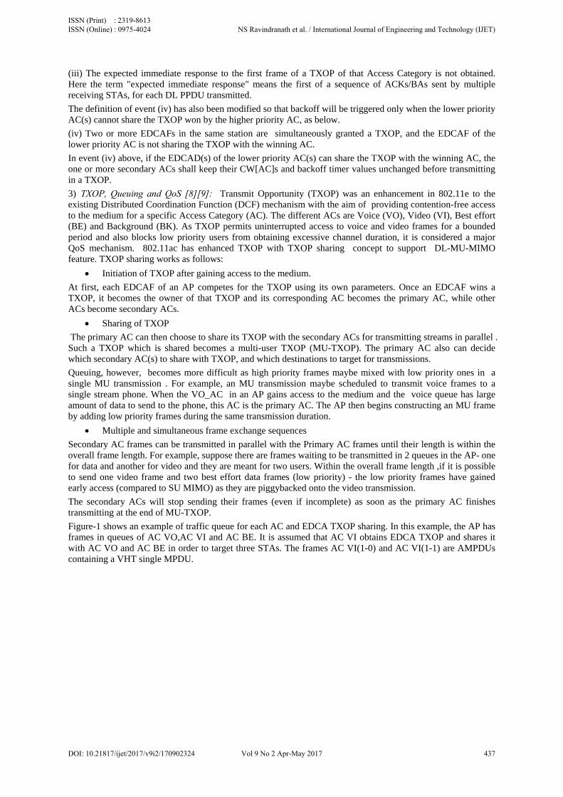
Figure-8 shows the channel sounding and MU-MIMO transmission protocols defined in IEEE 802.11ac. When the AP performs channel sounding at a given time, it announces the beginning of a sounding process by transmitting a null-data packet announcement (NDPA). After a short inter frame space (SIFS), the AP transmits a null-data packet (NDP), in which each AP antenna sequentially transmits a known signal for channel estimation. As shown in the figure, the multi-user mechanism necessitates a response from all beamformees, for which purpose, the Beamforming report poll frame is added. After a SIFS, a predestinated node feeds back the CSI. After a SIFS again, the AP polls a next node, and the polled node feeds back the CSI after a SIFS until there is no remaining node to be polled for CSI feedback. The multiple responses are combined by the beamformer resulting in a master steering matrix.
The NDP announcement frame, NDP frame and compressed beamforming action frame are same as in Transmit Beamforming. The 802.11ac MAC protocol defines capability (number of SS, MCS,..) negotiation for all the transmissions happening in parallel.
ISSN (Print) : 2319-8613 ISSN (Online) : 0975-4024 NS Ravindranath et al. / International Journal of Engineering and Technology (IJET)
DOI: 10.21817/ijet/2017/v9i2/170902324 Vol 9 No 2 Apr-May 2017 441
After the AP transmits packets to the primary and secondary users, the primary user transmits a block acknowledgement (BA) after a SIFS. Then, the AP transmits a BA request (BAR) for one of the secondary users after a SIFS, and the polled node transmits a BA after a SIFS until there is no remaining node to be polled. This is shown in figure-9.
4) Precoding [12][13][14]: Precoding techniques play a major role in the performance of MU-MIMO transmission. In this regard, there are two major classes of precoding namely, non-linear and linear precoding.
Non-linear precoding techniques are recognized to be useful for obtaining the maximum throughput possible. Some of these non-linear precoding techniques are Tomlinson-Harashima precoding (THP), Vector Perturbation (VP) and Lattice Reduction Aided (LRA) methods. However, these techniques have a very high level of complexity caused by the requirement of additional processing at the receiver and are also not supported by 802. l1ac.
Linear precoding techniques (Dirty Paper Coding (DPC), Zero Forcing and Block Diagonalization (BD)) on the other hand are low-complexity transmission techniques and are supported by 802.11ac. For a Gaussian MIMO channel, DPC can achieve the highest capacity region. The sum capacity in a MIMO broadcast channel is the capacity aggregation of all the users. Although DPC can achieve the maximum gain, it is more of a theoretical concept and real time implementation of DPC is very complex.
Zero forcing technique for MU-MIMO, does not require the channel information of other users and uses the pseudo inverse of the current user channel. Although this method is uncomplicated compared to BD, it is suboptimal in the sense that it does not nullify the inter user interferences effectively. However , at lower SNR cases, this algorithm works better than BD.
BD, an extension of zero forcing precoding for MU-MIMO systems is a simple algorithm that can reach a sum capacity comparable to that of DPC - with an implementation that is much easier than DPC. Here, each user’s precoding matrix lies in the null space of all the other users’ channels. If the channel matrices are perfectly known at the transmitter, then there is no interference at each receiver.
5) User selection: Since total numbers of users are generally more than the number of users which can be supported at the AP, optimal users with good CSI can be selected to improve the throughput of MU-MIMO system. The most favorable user can be identified by extensive investigation, although it necessitates computational complexity as the number of users increases. Greedy user selection, an algorithm with less complexity, chooses one user at each iteration. Complexity and performance of the algorithm depend on the user selection metrics such as Frobenius norm (FN) or Chordal distance(CD).
6) Detection Mechanisms[11]: Additionally, at the receiver side, the independent signals will need to be separated by using a technique called MIMO detection. Traditional MIMO detection methods include the well known linear MMSE as well as the vertical-Bell laboratories layered space-time (V-BLAST) and LRA decoders. V-BLAST and LRA techniques improve the performance of the simple MMSE-MIMO decoder. Another high performance MIMO detection algorithm is called the Maximum Likelihood Detection (MLD) algorithm. MLD algorithm has a very high level of complexity and are is hence impractical.
ISSN (Print) : 2319-8613 ISSN (Online) : 0975-4024 NS Ravindranath et al. / International Journal of Engineering and Technology (IJET)
DOI: 10.21817/ijet/2017/v9i2/170902324 Vol 9 No 2 Apr-May 2017 442

III. ADVANTAGES AND LIMITATIONS OF MU MIMO [7]
A. Advantages
1) MU MIMO uses the beamforming feature to transmit data simultaneously to receivers spatially separated thus acting like a 802.11 “switch.”
2) When both router and client have enabled MU-MIMO, the Channel Band Width (CBW) is very efficiently utilized.
3) Having a network with a better means of handling bandwidth means you'll get faster buffering, lower latency and more consistent and stable download speeds. These benefits are extremely useful for gaming, full-time HDTV streaming and heavy internet usage.
MU-MIMO has the potential to decrease network load by enabling parallel transmissions and thereby reducing latency . Thus ,even a few 802.11ac devices may benefit the entire network by decreasing airtime demand. Real-time streaming applications such as voice, video conferencing and video chat benefit primarily from lower latency.
4) MU-MIMO increases both speed and capacity and thus enhances the number of devices connected to a home network and the performance in public Wi-Fi hotspots.
B. Limitations
1) MU-MIMO feature is implemented only in downlink i.e. AP to client. But, as traffic is mostly in this direction, so DL-MU-MIMO feature is definitely an advantage. When MU-MIMO is supported in both uplink and downlink, then the complete benefits of such a feature can be realized in newer WLAN standards.
2) Data reception with MU-MIMO is better if the Wi-Fi device does not change its location. So watching a video on your smart phone while walking at home is not a smart idea as the router may decide to switch over to SU-MIMO, to avoid degradation in other stationary MU-MIMO connections.
3) When using multiple streams for communication, because of the manner in which the signal streams are processed, the benefit of MU-MIMO is more noticeable when the two devices (say a laptop and a desktop) are spatially separated in two different rooms rather than on the same study table.
4) MU-MIMO at the router translates to complexity in handling data streams. Hence the trouble shooting is also complex and involves examining the advanced settings of the router.
C. Calculation of PSDU length
PSDU length (parameter returned in the PLME_TXTIME confirm primitive for a VHT SU PPDU) when Binary Convolution Code (BCC) encoding is used is calculated using the formula[3]:
8
PSDU length (parameter returned in the PLME_TXTIME confirm primitive for a VHT SU PPDU) is calculated using the formula:
, ,
8 �
_ _ ,
8 �
where
PSDULENGTH is rounded down to the largest integer.
NSYM = number of symbols in the data field is calculated as
N max N ,
where N , N _ , for BCC users.
and NSYM_init,u for user u in BCC is calculated as
, 8 _ ,
,
It may be noted that Ntail and NES do not exist when LDPC is used in the place of BCC.
NDBPS,u = Number of data bits per symbol for user 'u', where u=0 to Nuser-1 Nuser = Number of users in the transmission. Nservice=Number of bits in the SERVICE field.
ISSN (Print) : 2319-8613 ISSN (Online) : 0975-4024 NS Ravindranath et al. / International Journal of Engineering and Technology (IJET)
DOI: 10.21817/ijet/2017/v9i2/170902324 Vol 9 No 2 Apr-May 2017 443

Ntail= Number of tail bits per BCC encoder. NES,u = Number of BCC encoders for user 'u', where u=0 to Nuser-1
IV. SIMULATIONS
MATLAB R2016a [15] version has incorporated a WLAN System Toolbox with provision to design, configure the physical layer in IEEE 802.11ac WLAN standard and to simulate, analyze and test the performance of WLAN communications systems.
Here,4 scenarios are discussed to show how MU-MIMO finds application in real time situations. The first one is analyzed mathematically while MATLAB results are shown for the other three.
The following table is used to calculate the aggregate data rates achieved in different scenarios.
Table-1. Aggregate Data Rate Calculation
MCS 20 MHz data rate (Mbps) (1SS,SGI)
SS multiplication factor
CBW multiplication factor
Max 40 MHz rate (Mbps) (8SS,SGI)
Max 80 MHz rate (Mbps) (8SS,SGI)
Max 160 MHz rate (Mbps) (8SS,SGI)
MCS0 7.2 ×2 for 2 streams ×3 for 3 streams ×4 for 4 streams ×5 for 5 streams ×6 for 6 streams ×7 for 7 streams ×8 for 8 streams
×1 for 20MHz ×2.1 for 40MHz ×4.5 for 80MHz ×9 for 160MHz
120 260 520
MCS1 14.4 240 520 1040
MCS2 21.7 360 780 1560
MCS3 28.9 480 1040 2080
MCS4 43.3 720 1560 3120
MCS5 57.8 960 2080 4160
MCS6 65.0 1080 2340 4680
MCS7 72.2 1200 2600 5200
MCS8 86.7 1440 3120 6240
MCS9 96.3 1600 3466.7 6933.3
A. Scenario-1
The case study in figure-10 is with a 4-Antenna AP communicating with four 1-antenna stations which are for example hand-held antennas. The PHY link rate in this configuration is 867 Mbps to each STA leading to an aggregate speed of (4×867) Mbps = 3.39 Gbps.
FIGURE-10: MU-MIMO SCENARIO-1
1) Configuration for Scenario-1:
CBW: 160 MHz
Number of Users: 4
User Positions: [0 1 2 3]
Number of Transmit Antennas: 4
Number of Space Time Streams for user 1, 2, 3 and 4: 1, 1, 1, 1
ISSN (Print) : 2319-8613 ISSN (Online) : 0975-4024 NS Ravindranath et al. / International Journal of Engineering and Technology (IJET)
DOI: 10.21817/ijet/2017/v9i2/170902324 Vol 9 No 2 Apr-May 2017 444
MCS values for user 1, 2, 3 and 4: 9, 9, 9 and 9
Type of Channel Coding: BCC or Binary Convolution Coding
APEP Length or number of bytes assigned to user 1, 2, 3 and 4: 2000, 1400, 1800, 2000
Guard Interval: Long.
2) MATLAB results for Scenario-1:
PSDU lengths (which is a function of both the APEP length and the MCS value) for the four users = 2336 2336 2336 2336
Different fields in the PLCP header (LSTF, LLTF, LSIG, VHTSIGA, VHTSTF, VHTLTF and VHTSIGB) are extracted in the four user devices independently and parameters such as bandwidth, group ID, APEP length and MCS values retrieved using these fields. Based on this, the VHTData for each user is received.
The packet length is extracted from the VHT-SIG-B information bits. For MU operation with 160 MHz,
Packet length for the 4 users = 2000 1400 1800 2000
The extracted APEP length matches the value set in the transmit end.
The MCS values are extracted from the VHT-SIG-B information bits (bits 20 to 23)
MCS for each user u1,u2,u3,u4 = 9, 9,9,9
It is seen that four users are able to receive their individual APEP packet lengths at the set MCS values after demodulation at receiver. Hence, MU MIMO functionality is operational
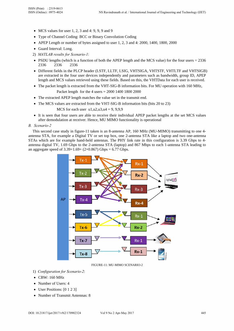
B. Scenario-2
This second case study in figure-11 taken is an 8-antenna AP, 160 MHz (MU-MIMO) transmitting to one 4-antenna STA, for example a Digital TV or set top box, one 2-antenna STA like a laptop and two one-antenna STAs which are for example hand-held antennas. The PHY link rate in this configuration is 3.39 Gbps to 4-antenna digital TV, 1.69 Gbps to the 2-antenna STA (laptop) and 867 Mbps to each 1-antenna STA leading to an aggregate speed of 3.39+1.69+ (2×0.867) Gbps = 6.77 Gbps.
FIGURE-11: MU-MIMO SCENARIO-2
1) Configuration for Scenario-2:
CBW: 160 MHz
Number of Users: 4
User Positions: [0 1 2 3]
Number of Transmit Antennas: 8
ISSN (Print) : 2319-8613 ISSN (Online) : 0975-4024 NS Ravindranath et al. / International Journal of Engineering and Technology (IJET)
DOI: 10.21817/ijet/2017/v9i2/170902324 Vol 9 No 2 Apr-May 2017 445
Number of Space Time Streams for user 1, 2, 3 and 4: 4, 2, 1, 1
MCS values for user 1, 2, 3 and 4: 9, 9, 9 and 9
Type of Channel Coding: BCC or Binary Convolution Coding
APEP Length or number of bytes assigned to user 1, 2, 3 and 4: 2000, 1400, 1800, 2000
Guard Interval: Long.
2) MATLAB results for Scenario-2:
PSDU lengths for the four users = 9353 4675 2336 2336
Packet length for the 4 users = 2000 ,1400, 1800, 2000
MCS for each user u1,u2,u3,u4 = 9, 9,9,9
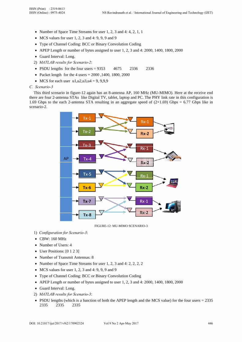
C. Scenario-3
This third scenario in figure-12 again has an 8-antenna AP, 160 MHz (MU-MIMO). Here at the receive end there are four 2-antenna STAs like Digital TV, tablet, laptop and PC. The PHY link rate in this configuration is 1.69 Gbps to the each 2-antenna STA resulting in an aggregate speed of (2×1.69) Gbps = 6.77 Gbps like in scenario-2.
FIGURE-12: MU-MIMO SCENARIO-3
1) Configuration for Scenario-3:
CBW: 160 MHz
Number of Users: 4
User Positions: [0 1 2 3]
Number of Transmit Antennas: 8
Number of Space Time Streams for user 1, 2, 3 and 4: 2, 2, 2, 2
MCS values for user 1, 2, 3 and 4: 9, 9, 9 and 9
Type of Channel Coding: BCC or Binary Convolution Coding
APEP Length or number of bytes assigned to user 1, 2, 3 and 4: 2000, 1400, 1800, 2000
Guard Interval: Long.
2) MATLAB results for Scenario-3:
PSDU lengths (which is a function of both the APEP length and the MCS value) for the four users = 2335 2335 2335 2335
ISSN (Print) : 2319-8613 ISSN (Online) : 0975-4024 NS Ravindranath et al. / International Journal of Engineering and Technology (IJET)
DOI: 10.21817/ijet/2017/v9i2/170902324 Vol 9 No 2 Apr-May 2017 446
Packet length for the 4 users = 2000 ,1400, 1800, 2000
MCS for each user u1,u2,u3,u4 = 9, 9,9, 9
V. CONCLUSION
It is seen that MU MIMO helps in distributing data to 4 users simultaneously using the space streams obtained through smart antennas. This is a major improvement over the limitation imposed by the MAC algorithm used in WLANs where stations can only gain access one following the other. Hence, latency and also throughput can be increased for multimedia applications. Also, the following Functional blocks have been identified to be key in MU MIMO performance:
a) PHY layer : Sounding, Precoding and detection techniques.
b) MAC layer : Aggregation, TXOP and back off mechanisms
These areas would then be the points of interest to future researchers who wish to enhance MU MIMO performance.
Research is proposed in PHY(Algorithmic improvements in Precoding and detection) and in MAC - Design a scheduler to optimise aggregation and TXOP/back off mechanisms to improve QoS for multiple users.
REFERENCES [1] 802.11n-2009. IEEE Standard for Information technology. Local and metropolitan area networks. Speciic requirements -Part 11:
Wireless LAN Medium Access Control (MAC) and Physical Layer (PHY) Speciications Amendment 5: Enhancements for Higher Throughput, E-ISBN: 978-0-7381-6046-7, INSPEC Accession Number: 10973933; 2009. p. 1–565.
[2] Elda Perahia, Robert Stacey, 2008, "Next Generation Wireless LANs Throughput, Robustness and Reliability in 802.11n", Cambridge University Press
[3] 802.11ac-2013. IEEE Standard for Information technology. Telecommunications and information exchange between systems Local and metropolitan area networks. Specific requirements - Part 11: Wireless LAN Medium Access Control (MAC) and Physical Layer (PHY) Specifications Amendment 4: Enhancements for Very High Throughput for Operation in Bands below 6 GHz. E-ISBN: 978-0-7381-8860-7, INSPEC Accession Number: 13957406; 2013. p. 1–425
[4] Elda Perahia, Robert Stacey, "Next Generation Wireless LANs: 802.11n and 802.11ac", Cambridge University Press, 2013 [5] N.S. Ravindranath, Inder Singh, Ajay Prasad and V.S. Rao, "Performance Evaluation of IEEE 802.11ac and 802.11n using NS3",
Indian Journal of Science and Technology, July 2016, DOI: 10.17485/ijst/2016/v9i26/93565 [6] Chunhui Zhu, Chiu Ngo Anirudh Bhatt Youngsoo Kim, "Enhancing WLAN backoff procedures for downlink MU-MIMO support",
2013 IEEE Wireless Communications and Networking Conference (WCNC), 2013, 368 - 373 [7] XIRRUS White Paper, "802.11ac Demystified-High Performance Wireless Networks" examples [8] Zhiqun Hu; Xiangming Wen; Zhaoxing Li; Zhaoming Lu; Wenpeng Jing, "Modeling the TXOP Sharing Mechanism of IEEE 802.11ac
Enhanced Distributed Channel Access in Non-Saturated Conditions", IEEE Communications Letters, 2015, Volume: 19, Issue: 9, Pages: 1576 - 1579
[9] Matthew S. Gast, "Wi-Fi at Gigabit and Beyond 802.11ac A Survival Guide", O Reilly Media, 2015 [10] Osama Aboul-Magd; Uikun Kwon; Youngsoo Kim; Chunhui Zhu, "Managing downlink multi-user MIMO transmission using group
membership", IEEE Consumer Communications and Networking Conference (CCNC), 2013 [11] Daisuke Nojima; Leonardo Lanante; Yuhei Nagao; Masayuki Kurosaki; Hiroshi Ochi, "Performance evaluation for multi-user MIMO
IEEE 802.11ac wireless LAN system", 2012 14th International Conference on Advanced Communication Technology (ICACT), 2012, Pages: 804 - 808
[12] Daisuke Nojima; Leonardo Lanante; Yuhei Nagao; Masayuki Kurosaki; Hiroshi Ochi, "Performance evaluation for multi-user MIMO IEEE 802.11ac wireless LAN system", 2012 14th International Conference on Advanced Communication Technology (ICACT), 2012, Pages: 804 - 808
[13] A P Theeksha; S. Srikanth, "Performance analysis and mode selection of SU-MIMO and MU-MIMO in 802.11ac", International Conference on Recent Trends in Information Technology (ICRTIT), 2013 IEEE
[14] Woochang Lim; Gibum Kim; Jinwoo Kim; Hyuncheol Park; Keunmoo Lee; Hanyoung Jang, "Performance of linear precoding and user selection in IEEE 802.11ac downlink MU-MIMO system", 2014 IEEE Wireless Communications and Networking Conference (WCNC)
[15] www.mathworks.com.
AUTHOR PROFILE
N.S. Ravindranath received his Bachelor's degree in Engineering from Mysore University, Karnataka, India in Electronics and Communications and M.S. degree from BITS, Pilani, India in Software Systems. He has been working in the Telecom industry for more than 25 years. He was associated with leading organizations such as Indian Telephone Industries Limited, Mahindra Satyam and Tata Elxsi working in the areas of Telecom, Networking and Wireless technologies. In the wireless domain, the areas of expertise include WLAN 802.11n, WiMAX, LTE, GPRS, DECT WLL and Digital Microwaves.
Dr.Inder Singh holds M.Sc.(IT), M.Tech(IT) and Ph.D. degrees. He is a Microsoft Certified Professional, IBM DB2 certified, e-commerce certification from Asset International. He is an Assistant Professor (SS) at University of Petroleum & Energy Studies, Dehradun, India. He has over 14 years of working experience. He has worked as Systems Administrator for 6 Years. His current areas of interest are Computer Networks, Cloud Computing & Virtualization, Strategic Information systems and e-Business.
ISSN (Print) : 2319-8613 ISSN (Online) : 0975-4024 NS Ravindranath et al. / International Journal of Engineering and Technology (IJET)
DOI: 10.21817/ijet/2017/v9i2/170902324 Vol 9 No 2 Apr-May 2017 447

Dr. Ajay Prasad holds a Ph.D. in Computer Science and Engineering in the area of cloud security, M.Tech (CSE)and a Masters of Computer Applications. He has more than 14 years of experience in faculty positions at reputed institutions and substantial industrial exposure. He has specialized in Computer Architecture, Simulation and Modeling, Security Principles, System Programming, Cloud Systems and Compilers. He is a reviewer in various reputed journals like JCNSS (hindawi.com), IJS (cscjournals.org), IJCSIS (sites.google.com/site/ijcsis), JECI (academicjournals.org). He is a Life member of Institute of Electronics and Telecom Engineers (IETE) and Indian Society for Technical Education IETE, ISTE and a Member of Computer Society of India. He has been a Technical Advisor to Geo Edge Modelling and Mapping Consultants Since 2010.He has held various roles during academic tenure, some of them being Program Head, (CyberLaw, Cyber Forensics, Graphics and Gaming, CIT, UPES), ABET Departmental representative at Sharda University, Member BoS Dept of IT Sharda University, Head IT Support (Sir Padampat Singhania University).
Dr. V. Sambasiva Rao, Professor in ECE Department of PES University, Bengaluru since July 2011, is an engineering graduate (1973) from College of Engineering, Kakinada (Andhra University) and obtained Ph.D from BITS, Pilani in 2010. For over 37 years ( April 1974 to June 2011), he was associated with ISRO in various capacities and superannuated in June 2011 as Deputy Director, ISRO Satellite Centre. In ISRO, he was primarily responsible for the development of high bit rate data transmitters for all IRS series of satellites and various RF and microwave systems in S, C, X, Ku and Ka bands for IRS and INSAT missions. He is a Senior Member of IEEE, Fellow of IETE, Member of IET and a Member of Astronautical Society of India. He received five distinguished awards and published 75 technical papers. Currently, apart from teaching UG/PG students, he is guiding students for developing student satellite and also has established an S-band ground station at PES University campus.
ISSN (Print) : 2319-8613 ISSN (Online) : 0975-4024 NS Ravindranath et al. / International Journal of Engineering and Technology (IJET)
DOI: 10.21817/ijet/2017/v9i2/170902324 Vol 9 No 2 Apr-May 2017 448