Study on impact properties of creep-resistant steel ... OnLine-First/0354... · STUDY ON IMPACT...
14
STUDY ON IMPACT PROPERTIES OF CREEP-RESISTANT STEEL THERMALLY SIMULATED HEAT AFFECTED ZONE Radivoje M.MITROVIĆ a , Dejan B.MOMČILOVIĆ b , Olivera A. ERIĆ* c , Ivana D. ATANASOVSKA c , and Nenad T.HUT b a Faculty of Mechanical Engineering, University of Belgrade, Serbia b Institute for testing of materials IMS, Belgrade, Serbia c Institute "Kirilo Savić", Belgrade, Serbia The steam pipe line (SPL) and steam line material, along with its welded joints, subject to damage that accumulates during operation in coal power plants. As a result of thermal fatigue, dilatation of SPL at an operating temperature may lead to cracks initiation at the critical zones within heat affected zone (HAZ) of steam pipe line welded joints. By registration of thermal cycle during welding and subsequent HAZ simulation is possible to obtain target microstructure. For the simulation is chosen heat resisting steel, 12H1MF (designation 13CrMo44 according to DIN standard). From the viewpoint of mechanical properties, special attention is on impact toughness mostly because very small number of available references. After simulation of single run and multi run welding test on instrumented Charpy pendulum. Metallographic and fractographic analysis is also performed, on simulated 12H1MF steel from service and new, unused steel. The results and correlation between microstructure and impact toughness is discussed, too. Key words: heat resisting steel, heat affected zone, instrumented Charpy test, impact toughness 1. Introduction Steam pipe lines undergo very complex service conditions, fatigue –creep and low cycle thermal fatigue at elevated temperatures, and, from a safety aspect, are the very significant system of a coal power plants. ____________________________________________ * Corresponding author: [email protected] Therefore, the steam pipe line and steam line material, along with its welded joints, subject to damage that accumulates during operation which can lead to fracture.
Transcript of Study on impact properties of creep-resistant steel ... OnLine-First/0354... · STUDY ON IMPACT...
STUDY ON IMPACT PROPERTIES OF CREEP-RESISTANT STEEL THERMALLY SIMULATED HEAT AFFECTED ZONE
Radivoje M.MITROVIĆ a, Dejan B.MOMČILOVIĆb, Olivera A. ERIĆ*c, Ivana D. ATANASOVSKAc, and Nenad T.HUTb
a Faculty of Mechanical Engineering, University of Belgrade, Serbia
b Institute for testing of materials IMS, Belgrade, Serbia c Institute "Kirilo Savić", Belgrade, Serbia
The steam pipe line (SPL) and steam line material, along with its welded joints,
subject to damage that accumulates during operation in coal power plants. As a
result of thermal fatigue, dilatation of SPL at an operating temperature may
lead to cracks initiation at the critical zones within heat affected zone (HAZ) of
steam pipe line welded joints.
By registration of thermal cycle during welding and subsequent HAZ simulation
is possible to obtain target microstructure. For the simulation is chosen heat
resisting steel, 12H1MF (designation 13CrMo44 according to DIN standard).
From the viewpoint of mechanical properties, special attention is on impact
toughness mostly because very small number of available references. After
simulation of single run and multi run welding test on instrumented Charpy
pendulum. Metallographic and fractographic analysis is also performed, on
simulated 12H1MF steel from service and new, unused steel. The results and
correlation between microstructure and impact toughness is discussed, too.
Key words: heat resisting steel, heat affected zone, instrumented Charpy test,
impact toughness
1. Introduction
Steam pipe lines undergo very complex service conditions, fatigue –creep and low cycle thermal
fatigue at elevated temperatures, and, from a safety aspect, are the very significant system of a coal power
plants.
____________________________________________ * Corresponding author: [email protected]
Therefore, the steam pipe line and steam line material, along with its welded joints, subject to
damage that accumulates during operation which can lead to fracture.

From the standpoint of energy efficiency, these accumulations of damage make a vital
understanding of all influential factors that contribute to degradation of material properties over longer
period of time [1].
There are two main causes of degradation of material properties of steam pipe lines (SPL):
� Interaction between fatigue - creep (low cycle and thermal fatigue); and
� Primary stresses induced by the weight of the steam line itself, noted above, and the influence of
hangers on secondary induced stresses [2].
As a result of thermal fatigue, dilatation of SPL at an operating temperature may lead to cracks
initiation at the critical zones within heat affected zone (HAZ) of welded joints [3]. We should not forget
the residual stresses due to welding that can be superimposed with operating stresses, and can also be
induce initiation of cracks [4, 5]. It is necessary to mention the corrosion and stress corrosion as another
possible cause of initiation of cracks in the steam line [6, 7]. However, the most significant effect on the
occurrence of damage and reduction of SPL service life of materials has the appearance of creep [8].
Development of material damage during the operation is followed by the continuous creation of
cavities or micropores at grain boundaries. Many authors state that the cavities were present before the
process of creep, as a result of SPL steel production process. Regardless of background, the cavities grow
during creep [9, 10]. Cavity size is largely dependant also on material type, however it is in the range of
micron size (often also lower), therefore they are usually called “microvoids” or “micro-cavities”. One of
the basic acceptance tests of welds and heat affected zone is impact energy test by Charpy method. The
classic energy impact testing, without separation of energy initiation and energy propagation of crack
during the tests, does not give a complete view situation of the impact strength of the tested material.
Therefore, in these studies, it is necessary to use instrumented Charpy pendulum [11, 12].
Knowledge of the microstructure and their variations with different thermal cycles of welding and
impact energy dependence of the microstructure, can be obtained by improving the welding parameters
during welding repair on the one hand, and making assessment of the existing welds from the point of
remaining service life, energy efficiency and behavior of welded joints during accidental situations, on the
other hand [13].
By registering during welding thermal cycle, during welding of full scale pipe, and then
simulating obtained welding cycle on simulators, on samples of material from which the SPL is made, it is
possible to obtain the desired microstructure corresponding to the selected critical microstructure within
the HAZ, but in dimensions sufficient for reliable testing of destruction which is the aim this paper.
2. Experiment
2.1. Methodology and equipment
Today, welding simulators are used to determine mechanical properties of the "weakest link" i.e.
critical microstructure within a HAZ. Welding simulator (fig. 1) is a device that achieves controlled
heating and cooling similar to the thermal cycle during welding. The difference is in obtained micro
structure, on a sample size of 10 x 10 x 60 mm, and at its middle part, as microstructure which

corresponds to the desired critical area. The critical area of HAZ is usually coarse grain zone, and
simulation enables the exact identification of fundamental mechanical properties [14, 15]. Input
parameters are performed via computer, and selection of the basic parameters can be determined from the
calculation of the temperature field or by the using of appropriate equations to calculate ∆t8/5 in the
welding thermal cycle [16]. The origin of the parameters can be also experimental obtained, by measuring
the thermal cycle with the thermocouples.
In order to obtain experimental values comparable with existing from literature (and each other),
for testing was selected (and sampled steel) from exploitation (marked as old pipe - OP), and a new
unused steel pipe (marked as new pipe - NP).
In both cases, the used steal was 12H1MF according to GOST 20072-74, [17]. In both group of
specimens, samples were cut from the tube diameter ∅245x22 mm. Basic data for OP group of specimens,
taken from the coal power plant is the working temperature of 509 - 520oC, working pressure 130 bar and
230 start-up, with a total of 72,000 hours spent in service.
Fig. 1. Heat affected zone simulator SMITWELD
Orientation and labeling of samples measuring 11x11x60 mm is shown in fig. 2. As can be seen
from fig. 2, samples are labeled L (longitudinal) and T (transversal), which indicate the position on the
tube wall thickness. Tube numbers 1-3 indicate the simulated samples as a single run welding of tubes,
while numbers 3-5 indicate the simulated samples as multi run welding.
Designation of specimens:
NT - New tube
OT - Old tube
L - Longitudinal direction
T - Transversal direction
1,2,3 Numbers of specimens simulated as singlerun HAZ
3,4,5, Numbers of specimens simulated as multirun HAZ
L
T
Specimens for metallographicexamination
Fig. 2 - Schematic presentation of specimens sampling from SPL tubes
In order to perform characterization of simulated specimens, the following tests were completed:

1. Examination of the chemical composition for each group of tubes;
2. Simulation of HAZ;
3. Hardness measurement in the zone -working part of the tube;
4. Examination of the impact energy with a instrumented Charpy pendulum SCHENCK TREBEL
300;
5. Metallographic examination close to the fracture site in the working part of the tube below the
point, fig. 2 -hatched area; and,
6. Fractography examination of a breaking surface tubes with a scanning electron microscope (SEM)
Phillips 515.
The sequence of tests above is also the methodology and reliable determination of the tested
impact toughness characteristics of the critical areas within the HAZ.
2.2. HAZ simulation parameters
Simulation of steel 12H1MF samples was performed on the simulator Smitweld LS1402, on the
Welding Institute in Timisoara, Romania. A simulation of thermal cycles and thermal treatment was
carried out for all these combinations of specimen groups, NP-L, NP-T, OP-L and the OP-T:
� The constant heating rate until reaching the maximum temperature of the cycle – Pt for 10s;
� Cooling rate in the range of 800 - 500oC, according to the thickness of 22 mm, of the upper limit of
T/t8/5 = 30oC/s which corresponds to t8/5 = 10s;
� The maximum temperature in the simulated cycle, in the case of a single run welding Pt = 1350oC
(designation: single pass simulation - SPS);
� Maximum temperatures in the simulated cycle, in the case of a multi run welding Pt = 1300oC,
1200oC, and 1000oC (designation: multi pass simulation - MPS); and,
� Thermal treatment after conducted simulation of multi layer welding at 500oC for 3 hours.
After simulation of samples with dimensions 11 x 11 x 60 mm, standard Charpy specimens were
made according to EN 10045-1, with the standard V notch.
2.3. Base material properties
The chemical composition of tested samples correspond with the standard requirements, tab. 1. The results
of mechanical properties testing are presented in tab. 2. Obtained results are above minimal required
values by standard GOST 20072/74 [17].
Table 1. Chemical composition of 12H1MF prema GOST-u 20072/74
%C %Si %Mn %S %P %Cr %V %Mo %Cu %Ni 0,08-0,15 0,17-0,37 0,40-0,70 0,025 0,030 0,90-1,20 0,15-0,30 0,25-0,35 0,20 max. 0,30 max.
Table 2. Mechanical properties of 12H1MF according to GOST 20072-74
Yield strength Re (MPa)
Tensile strength Rm (MPa)
Elongation A5 (%)
Impact toughness on + 20oC KV (J)
Vickers hardness HV5
239 434 24,3 59 117

3. Results 3.1. Hardness testing
Hardness measurement, HV5, was performed on the Charpy specimens according to standard EN
ISO 6507-1:2005. The scheme of hardness measurement is shown in fig. 3. The results of hardness
measurements are shown in tab. 3.
12345
Fig. 3. Hardness measurement points on Charpy specimens with 2 mm depth V notch. Tab. 3. The results of hardness measurements
HV5 Sample Simulation of welding
1 2 3 4 5 SPS 321 303 306 280 283 NPL MPS 317 313 303 303 303 SPS 293 321 286 299 298
NPT MPS 272 276 257 280 280 SPS 243 232 252 232 232
OPL MPS 164 172 175 106 146 SPS 220 241 199 232 241
OPT MPS 220 210 202 210 210
3.2. Impact toughness (Charpy) testing
Examination of the impact energy was carried out on Charpy instrumented pendulum, with
maximum impact energy of 300J. That made possible to determine not only the total, but also initiation
and propagation energy of the tested material. Test results are shown in tabs. 4 – 7:
Tab. 4. The results of impact energy for the sample group NPL Mark of group of samples, numbers of specimens and maximal temperature of
thermal cycle
Initiation energy, KV(J)
Propagation energy, KV (J)
Total energy, KV (J)
Average value KV (J)
13,0 12,6 25,6
34,0 11,8 45,8 SPS
(1350°C) 40,0 8,8 48,8
40,1
80,0 42,8 128,0
65,0 19,4 84,4
NPL MPS
(1300 oC, 1200 oC, 1000 oC) 90,0 46,3 136,3
116,2
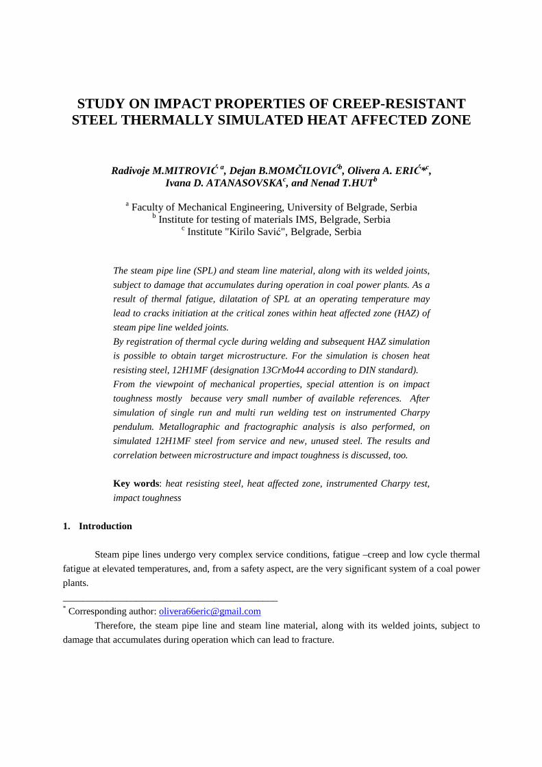
Tab. 5. The results of impact energy for sample group NPT Mark of group of samples, numbers of specimens and maximal temperature of
thermal cycle
Initiation energy, KV(J)
Propagation energy, KV (J) Total energy, KV
(J) Average value
KV (J)
9,0 4,7 13,7
12,0 6,8 18,8 SPS
(1350°C) 9,0 4,5 13,5
15,3
25,1 34,1 59,2
25,0 29,8 54,8
NPT MPS
(1300 oC, 1200 oC, 1000oC) 30,0 24,2 44,2
52,7
Tab. 6. The results of the impact energy for the sample group OPL
Mark of group of samples, numbers of specimens and maximal temperature of
thermal cycle
Initiation energy, KV(J)
Propagation energy, KV (J) Total energy, KV
(J) Average value
KV (J)
41,0 8,8 49,8
14,0 8,6 22,6 SPS
13500C 15,0 2,7 17,7
30,0
65,0 96,0 161,0
60,0 93,2 153,2
OPL MPS
(1300 oC, 1200 oC, 1000 oC) 60,0 84,9 144,9
152,9
Tab. 7. The results of impact energy for the sample group OPT Mark of group of samples, numbers of specimens and maximal temperature of
thermal cycle
Initiation energy, KV(J)
Propagation energy, KV (J) Total energy, KV
(J) Average value
KV (J)
6,0 12,0 18,0
12,0 22,1 34,1 SPS
13500C 6,0 7,4 13,4
30,0
14,0 46,4 60,4
15,0 21,9 36,9
OPT MPS
(1300 oC, 1200 oC, 1000 oC) 12,0 47,0 59,0
52,1
In fig. 4, the typical force-time diagrams of samples, are presented.
NPL - (typical diagram for single run simulated HAZ)
NPT - (typical diagram for single run simulated HAZ)

NPL - (typical diagram for multi run simulated HAZ)
NPT - (typical diagram for multi run simulated HAZ)
OPL - (typical diagram for single run simulated HAZ)
OPT - (typical diagram for single run simulated HAZ)
OPL - (typical diagram for multi run simulated HAZ)
OPT - (typical diagram for multi run simulated HAZ)
Fig. 4. The appearance of characteristic force-time diagram. 3.3. The results of metallographic examination by light microscopy (LM)
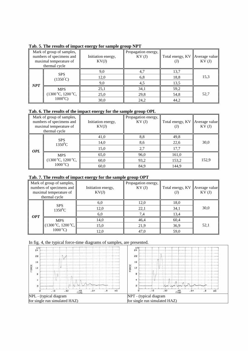
The samples for metallographic examination are made from broken specimens after Charpy
impact test. Reviewed places are schematically indicated in fig. 2. Microstructure of samples NPL and
OPL are shown in figs. 5 and 6. As the initial microstructure and the microstructure after the simulations
were identical on samples for testing both directions (L and T) groups, it will be shown only to
characteristic microstructures.
a) base material, ferrite -pearlite structure, x400 b) HAZ, single run welding simulated HAZ, x400
c) Detail from the picture 6b) single run welding, the
ferrite on bainite grain boundaries, x1000 d) multi run welding, ferrite – bainite structure x400,
Fig. 5. The microstructures of samples from NPL group
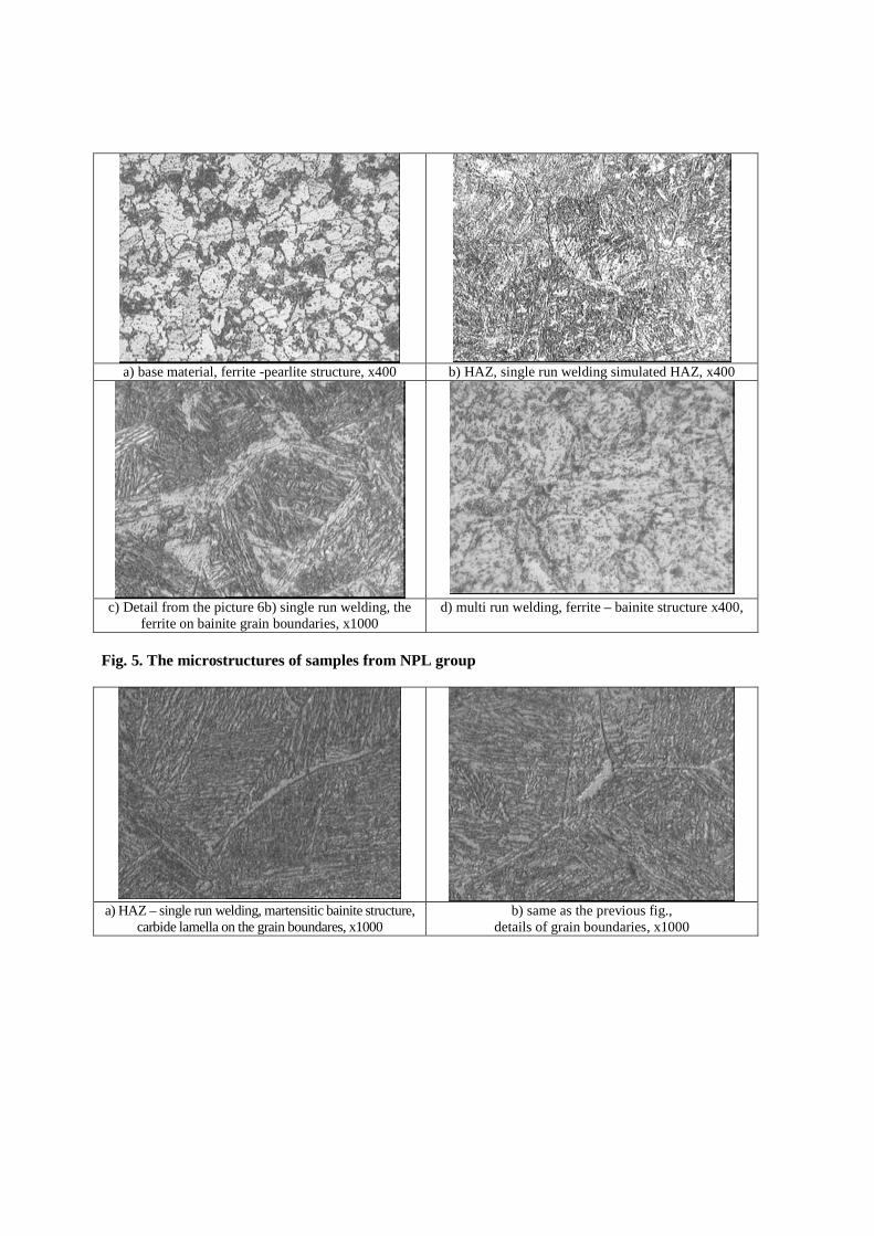
a) HAZ – single run welding, martensitic bainite structure,
carbide lamella on the grain boundares, x1000 b) same as the previous fig.,
details of grain boundaries, x1000

c) HAZ, multi run welding,
fine grain pearlite - bainitic microstructure, x400 Fig. 6. The microstructures of samples from OPL Group 3.4. SEM examination
The fractured surfaces of the broken Charpy specimens were examined with a scanning electron
microscope (SEM) Phillips 515. The figs 7 and 8 show the microstructure samples of OPL and NPL
group.
a) single run welding, brittle fracture, x30 b) single run welding, detail from previous fig., ductile
fracture at the grain boundaries, x100

c) multi run welding, detail of the notch root with bands of sulfides, x30
d) multi run welding, transition from notch root toward the center surfaces, brittle-ductile fracture, x200
e) detail from figure d, nonmetallic inclusions in the pits, x400
f) multi run welding, brittle fracture, area of unstable crack growth, x1000
Fig. 7. Fractography of samples from NPL group
a) single run welding, brittle fracture, x30 b) small inclusions and lamination, x100
c) Detail from fig. 8b, nonmetallic inclusions in the
pits, x400 d) Bainite lamella x1000

e) Sulphide inclusions, the grain boundaries ferrite x 400
Fig. 8. Fractography of samples from OPL group
4. Discussion
Hardness measurements on the samples of NPL and OPL (tab. 3), shows that the measured values
of hardness at the multi run welding are higher than on single run welding.
Based on the examination carried out in both groups of NP and OP specimens, it can be seen that
the tubes sampled from the longitudinal direction have higher values of impact energy in comparison to
the sampling tubes from the transversal direction. The elongated microstructure which would indicate that
higher impact energy values in longitudinal direction, was not confirmed or found neither in the simulated
HAZ nor in the base material. However, a significant amount of lamination caused by residual non-
metallic inclusions observed in figs 7, b), c) and e), indicate that there was a "lamination strengthening",
since their great number is observed. The influence of inclusions on the overall energy impact is negative.
However, in special cases, when a notch is perpendicular to the long axis of inclusions, comes to
lamination effect or “lamination strengthening”. Roughly explained, this straightening is primarily
reflected in examination of ten connected samples of size 1x10mm instead of a homogeneous sample test
with a cross-section dimension 10x10mm. As the lamination patterns become larger, a deformation of
tube parts between the non-metallic inclusions are deformed to a greater extent under the plain stress
condition. Apropos precisely described change of deformation, the total impact energy does not increase
due to the present of non-metallic inclusions, only the transient temperature toughness shifts to lower
temperatures [18, 19].
As expected, the lower values of impact energy with a simulated tube welding cycle are
quantitatively verified, in accordance with a literature. It was determined that there is a linear dependence
between density (i.e. number) of pores in materials, and the energy that is absorbed during impact testing.
Based on the value of impact strength, it was possible to show in this way that it can not only strengthen
the fact regarding formation of micropores due to creep, but also to estimate the size of the volume in the
unchanged structure. However, in the terms of industrial exploitation, the metal structure changes occurs
with an accumulation of micro-pores, and the effects on reduction of impact strength is very difficult to
separate [10]. Also, a great waste of steel from exploitation, (group OP), has been observed. This
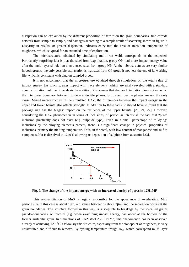
dissipation can be explained by the different proportion of ferrite on the grain boundaries, fine carbide
network from sample to sample, and damages according to a sample result of scattering shown in figure 9.
Disparity in results, or greater dispersion, indicates entry into the area of transition temperature of
toughness, which is typical for an extended time of exploration.
The microstructure, obtained by simulating multi run weld, corresponds to the expected.
Particularly surprising fact is that the steel from exploitation, group OP, had more impact energy value
after the multi layer simulation then unused steal from group NP. As the microstructures are very similar
in both groups, the only possible explanation is that steal from OP group is not near the end of its working
life, which is consistent with data on sampled pipes.
It is not uncommon that the microstructure obtained through simulation, on the total value of
impact energy, has much greater impact with trace elements, which are rarely reveled with a standard
classical titration volumetric analysis. In addition, it is known that the crack initiation does not occur on
the interphase boundary between brittle and ductile phases. Brittle and ductile phases are not the only
cause. Mixed microstructure in the simulated HAZ, the differences between the impact energy in the
upper and lower bainite also affects strongly. In addition to these facts, it should have in mind that the
package size has the biggest impact on the resilience of the upper bainite. [20, 21, 22]. However,
considering the HAZ phenomenon in terms of inclusions, of particular interest is the fact that “pure”
inclusion practically does not exist (e.g. sulphide type). Even in a small percentage of "alloying"
inclusions by the alloying elements present, there is a significant change in physical properties of
inclusions, primary the melting temperature. Thus, in the steel, with low content of manganese and sulfur,
complete sulfur is dissolved at 1240oC allowing re-deposition of sulphide from austenite [23].
120
80
40
0 0,2 0,4 0,6 0,8
OPT multipass(52,1 J)
Fig. 9. The change of the impact energy with an increased density of pores in 12H1MF
This re-precipitation of MnS is largely responsible for the appearance of overheating. MnS
particle size in this case is about 1µm, a distance between is about 2µm, and the separation occurs at the
grain boundaries. The structure formed in this way is susceptible to breakage by the so-called grains
pseudo-boundaries, or fracture (e.g. when examining impact energy) can occur at the borders of the
former austenitic grain. In simulations of HAZ steel 2.25 Cr1Mo, this phenomenon has been observed
already at achieving 1200oC. Obviously this structure, especially from the standpoint of toughness, is very
unfavorable and difficult to remove. By cycling temperature trough AC1, which correspond multi layer

welding, grain boundaries can be moved from this isolated, finely dispersed sulphide inclusions [24]. This
is a re-allocation of highly dispersed non-metallic inclusions during the cooling, and after reaching the
maximum cycle. As shown in fig. 8 b), inclusions were dispersed in the former austenite grain boundaries.
The intercrystal fracture has occurred precisely at these boundaries during the examination of the impact
energy.
5. Conclusion
Based on analysis of test results in this study obtained by thermal cycling heat simulator we can
conclude the following:
� The study found that the difference between the impact energy simulation between single run
welding and multi run welding was higher in the case of used materials such as group of OP
samples, than in fresh material of the group NP.
� A higher impact energy values within a group in test tubes from the longitudinal than the
transverse direction were detected.
� The presence of non-metallic inclusions is substantially affecting the character of fracture.
� The unstable fracture was also observed in OPL and NPL group samples, with relatively high
values of impact energy and simulated multi run welding.
� A significant change of a fracture mechanism was observed in OPL group samples in references
to exploitation steel simulation. In the simulation of the single layer welding almost entire
absorbed energy is used on the crack initiation, while the propagation energy is quite small. In a
simulation of multi run welding, most of the total absorbed energy is wasted on the propagation
energy.
� It is possible to obtain an optimal impact energy values in multi run welding by changing the
welding parameters for each cycle, without compromising other mechanical properties of HAZ.
Acknowledgement
This work has been supported by the Ministry of Science and Technological Development of the Republic
of Serbia under Projects: TR 35029 and TR 34015. References [1] Viswanathan R., Damage Mechanisms and Life Assessment of High Temperature Components,
ASM INTERNATIONAL,(1989), pp. 15-17 [2] Badet. H., Maintenance of High-Pressure / High-Temperature Piping in Fossil Fueled Power plants,
Alsthom Review, No 9, (1987), pp. 17-27 [3] Spera D.A., What is Thermal Fatigue? Thermal Fatigue of Materials and Components, ASTM STP
612, (1976), pp. 3-9 [4] Totten G., Howes M., T. Inoue, width et al. Handbook of Residual Stress and Deformation of Steel,
ASM International, Ohio, 2000, pp. 392-396 [5] Shipley R.J. Becker W.T., ASM Handbook Volume 11 Failure Analysis and Prevention, ASM
International, 2002, pp. 2686 - 2739 [6] Russel H. Jones, width et al., Stress- Corrosion Cracking Materials: Performance and Evaluation,
ASM International, 1993

[7] Landrum J. R., Fundamentals of Design for Corrosion Control - A Corrosion Aid to the Designer, NACE, Houston, 1989
[8] Singer J. G., Combustion Fossil Power Systems, Combustion Engineering, Inc.Windsor, CT, 1991 [9] Riedel, H., Fracture at High Temperatures, Springer-Verlag Berlin Heilderberg, 1987. [10] Chadek, Y., Creep of Metallic Materials (Russian translation), Mir Publishers Moscow, 1987. [11] Gooch D.J., Remnant Creep Life Prediction in Ferritic Materials, in: Comprehensive Structural
Integrity, Vol. 5: Creep and High Temperature Failures., Elsevier Pergamon, London, (2003), pp. 309-359
[12] Milovi ć, Lj., Vuherer, T., Zrilić, M., width et al. Study of the Simulated Heat Affected Zone of Creep Resistant 9-12% Advanced Chromium Steel, Materials and Manufacturing Processes, Volume 23, No 6: (2008), pp.597 - 602
[13] Milovi ć, Lj., Significance of cracks in the heat affected zone of steels for elevated temperature application, STRUCTURAL INTEGRITY AND LIFE Vol. 8, No 1 (2008), pp. 55–64
[14] Gliha, V., Vuherer, T., Ule, B., width et al., Fracture resistance of simulated heat affected zone areas in HSLA structural steel, Science and Technology of Welding and Joining, vol. 9, No. 5, (2004), pp. 399-406
[15] Dolby, R., E., Fracture Toughness Comparison of Weld HAZ and. Thermally Simulated Microstructures, Metal Construction and British Welding Journal, (1972), pp. 59-63
[16] Odanović, Z., Numerical modeling of heat transfer in arc welding of steel and anticipation of possible effects on the heat affected zone", Ph.D. thesis, Faculty of Technology and Metallurgy, University of Belgrade, 1993, pp. 39-43
[17] GOST 20072-74: Heat resisting steel. Specification [18] Kucera, J., width et al. On the fracture of laminated Charpy V notch specimens, Proc AEFM, Rome,
(1980), pp. 515-525 [19] Garde, A.M., Weiss, V., Met.trans. A, Vol 3, (1971-1972), pp. 2811-2817 [20] Naylor, J.P., Krahe, P.R., Met.trans. A, Vol.5, (1974), pp. 1699 - 1701 [21] Bhadeshia, H.K.D.H, Bainite in steels, The Institute of Materials, London, 1992, pp. 246-247 [22] Kiessling, R., Lange.N., Non-metalic inclusions in steel, The Institute of Materials, 1997, Section P,
pp. 54-73 [23] Pugh, S.F., An Introduction to Grain Boundary Fracture in Metals, London, The Institute of Metals,
1991, pp. 53; 89 [24] Lazić, V. N., width et al. Energetic Analysis of Hard Facing and Weld Cladding of an Air Powered
Drop Hammer Damaged Ram, THERMAL SCIENCE, (2010), Vol. 14, pp. S269-S284