STUDY OF THE INFLUENCE OF A GAP BETWEEN … OF THE INFLUENCE OF A GAP BETWEEN THE WING AND ... were...
6
Review of the Air Force Academy No 3 (30) 2015 39 The computation of the flow over a multi- element wing in high-lift configuration remains however one of the most difficult problems encountered in CFD [6]. The computations normally include a comprehensive code, coupled to Euler or Navier-Stokes solvers. The examples for a successful application of CFD are the codes FLUENT, OVERFLOW of NASA, FLOWer and TAU of Deutshes Zentrum für Luft und Raumfahr [2], [6], elsA and WAVES of ONERA [7], CFD++ [8], Star- CCM+ [9], [10], TAS of Takoku University and UPACS of Japan Institute of Space Technology and Aeronautics [10], [11]. The high-lift configurations considerably complicate the flow physics by boundary layer transition, separations and reattachments. Therefore it is very important to generate the appropriate mesh around it. The mesh can be structured, unstructured or hybrid. The structured mesh is identified by regular connectivity. The possible element choices are quadrilateral in 2D and hexahedral in 3D. The unstructured mesh is identified by irregular connectivity, [7], [12]. This grid typically employs triangles in 2D and tetrahedral in 3D. 1. INTRODUCTION Aircraft wing high-lift configuration design is an important and challenging part of the whole aircraft aerodynamic configuration design, even dealing with a 2-D high-lift configuration design task which is an essential step for the 3-D high-lift configuration design [1], [2], [3], [4]. During the take-off and landing of an aircraft, the performance of high-lift devices has strong impact on the operating costs and environment around airports, such as improvements of payload, fuel consumption, and noise emission. Take-off and landing performance for very light airplanes are governed by the requirements as EASA CS-VLA [5]. The take-off and landing distances, and the important speeds as the stall speed with flaps retracted – V S , the design maneuvering speed – V A , the speed with flaps fully deflected – V F , and the stall speed with flaps fully deflected – V SF , depend on aerodynamic characteristics of the wing with a flaps deflected. Nowadays, Computational Fluid Dynamics (CFD) is widely used for the prediction of the aerodynamic performance of the wing, at least in cruise flight. STUDY OF THE INFLUENCE OF A GAP BETWEEN THE WING AND SLOTTED FLAP ON THE AERODYNAMIC CHARACTERISTICS OF ULTRA-LIGHT AIRCRAFT WING AIRFOIL Cvetelina VELKOVA, Michael TODOROV Technical University of Sofia, Bulgaria DOI: 10.19062/1842-9238.2015.13.3.6 Abstract: The purpose of the study is to assess what should be the optimal distance of the gap between the wing and slotted flap should be in order to improve the aerodynamic characteristics of ultra-light aircraft wing. A numerical study was performed on a NACA 23012 airfoil with a single slotted flap to examine the aerodynamic coefficients at Reynolds number of 3×10 6 . The choice of the optimal distance of the gap between the wing and the slotted flap is made by comparison of its aerodynamic characteristics for two different cases in take-off stage. The numerical simulations were performed for two different lengths of slot, whose length is expressed as percentages of the airfoil chord. All calculations were made using a CFD code Fluent. Conclusions about the aerodynamic efficiency of the proposed configuration wing-single slotted flap were made. Keywords: airplane wing, single slotted flap, aerodynamic characteristics, CFD, Fluent.
Transcript of STUDY OF THE INFLUENCE OF A GAP BETWEEN … OF THE INFLUENCE OF A GAP BETWEEN THE WING AND ... were...

Review of the Air Force Academy No 3 (30) 2015
39
The computation of the flow over a multi-element wing in high-lift configuration remains however one of the most difficult problems encountered in CFD [6]. The computations normally include a comprehensive code, coupled to Euler or Navier-Stokes solvers. The examples for a successful application of CFD are the codes FLUENT, OVERFLOW of NASA, FLOWer and TAU of Deutshes Zentrum für Luft und Raumfahr [2], [6], elsA and WAVES of ONERA [7], CFD++ [8], Star-CCM+ [9], [10], TAS of Takoku University and UPACS of Japan Institute of Space Technology and Aeronautics [10], [11].
The high-lift configurations considerably complicate the flow physics by boundary layer transition, separations and reattachments. Therefore it is very important to generate the appropriate mesh around it. The mesh can be structured, unstructured or hybrid. The structured mesh is identified by regular connectivity. The possible element choices are quadrilateral in 2D and hexahedral in 3D. The unstructured mesh is identified by irregular connectivity, [7], [12]. This grid typically employs triangles in 2D and tetrahedral in 3D.
1. INTRODUCTION
Aircraft wing high-lift configuration design is an important and challenging part of the whole aircraft aerodynamic configuration design, even dealing with a 2-D high-lift configuration design task which is an essential step for the 3-D high-lift configuration design [1], [2], [3], [4]. During the take-off and landing of an aircraft, the performance of high-lift devices has strong impact on the operating costs and environment around airports, such as improvements of payload, fuel consumption, and noise emission. Take-off and landing performance for very light airplanes are governed by the requirements as EASA CS-VLA [5]. The take-off and landing distances, and the important speeds as the stall speed with flaps retracted – VS, the design maneuvering speed – VA, the speed with flaps fully deflected – VF, and the stall speed with flaps fully deflected – VSF, depend on aerodynamic characteristics of the wing with a flaps deflected.
Nowadays, Computational Fluid Dynamics (CFD) is widely used for the prediction of the aerodynamic performance of the wing, at least in cruise flight.
STUDY OF THE INFLUENCE OF A GAP BETWEEN THE WING AND SLOTTED FLAP ON THE AERODYNAMIC CHARACTERISTICS OF
ULTRA-LIGHT AIRCRAFT WING AIRFOIL
Cvetelina VELKOVA, Michael TODOROVTechnical University of Sofia, BulgariaDOI: 10.19062/1842-9238.2015.13.3.6
Abstract: The purpose of the study is to assess what should be the optimal distance of the gap between the wing and slotted flap should be in order to improve the aerodynamic characteristics of ultra-light aircraft wing. A numerical study was performed on a NACA 23012 airfoil with a single slotted flap to examine the aerodynamic coefficients at Reynolds number of 3×10⁶. The choice of the optimal distance of the gap between the wing and the slotted flap is made by comparison of its aerodynamic characteristics for two different cases in take-off stage. The numerical simulations were performed for two different lengths of slot, whose length is expressed as percentages of the airfoil chord. All calculations were made using a CFD code Fluent. Conclusions about the aerodynamic efficiency of the proposed configuration wing-single slotted flap were made.Keywords: airplane wing, single slotted flap, aerodynamic characteristics, CFD, Fluent.
Study of the Influence of a Gap Between the Wing and Slotted Flap on the Aerodynamic Characteristics of Ultra-Light Aircraft Wing Airfoil
40
The calculations were made for Reynolds number of Re=3×10⁶ (respectively V=43.81 m/s) at the sea level. The turbulent intensity and turbulent viscosity were 2.48% and 10 respectively. The flap deflection angle, δF, was 20º (take-off configuration).
The obtained results showed that the chosen arrangement of wing-single plain flap is not sufficiently effective from an aerodynamic point of view, although it is attractive with the simple design.
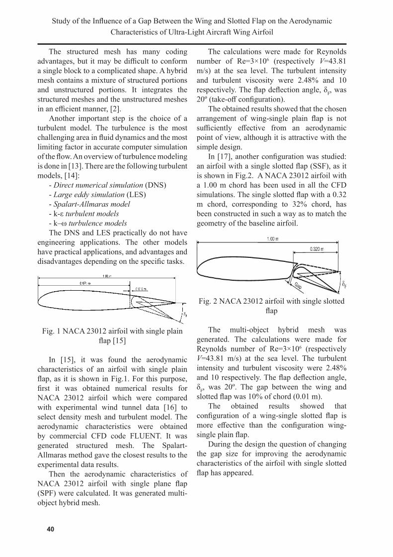
In [17], another configuration was studied: an airfoil with a single slotted flap (SSF), as it is shown in Fig.2. A NACA 23012 airfoil with a 1.00 m chord has been used in all the CFD simulations. The single slotted flap with a 0.32 m chord, corresponding to 32% chord, has been constructed in such a way as to match the geometry of the baseline airfoil.
Fig. 2 NACA 23012 airfoil with single slotted flap
The multi-object hybrid mesh was generated. The calculations were made for Reynolds number of Re=3×10⁶ (respectively V=43.81 m/s) at the sea level. The turbulent intensity and turbulent viscosity were 2.48% and 10 respectively. The flap deflection angle, δF, was 20º. The gap between the wing and slotted flap was 10% of chord (0.01 m).
The obtained results showed that configuration of a wing-single slotted flap is more effective than the configuration wing-single plain flap.
During the design the question of changing the gap size for improving the aerodynamic characteristics of the airfoil with single slotted flap has appeared.
The structured mesh has many coding advantages, but it may be difficult to conform a single block to a complicated shape. A hybrid mesh contains a mixture of structured portions and unstructured portions. It integrates the structured meshes and the unstructured meshes in an efficient manner, [2].
Another important step is the choice of a turbulent model. The turbulence is the most challenging area in fluid dynamics and the most limiting factor in accurate computer simulation of the flow. An overview of turbulence modeling is done in [13]. There are the following turbulent models, [14]:
- Direct numerical simulation (DNS) - Large eddy simulation (LES) - Spalart-Allmaras model- k-ε turbulent models - k–ω turbulence models The DNS and LES practically do not have
engineering applications. The other models have practical applications, and advantages and disadvantages depending on the specific tasks.
Fig. 1 NACA 23012 airfoil with single plain flap [15]
In [15], it was found the aerodynamic characteristics of an airfoil with single plain flap, as it is shown in Fig.1. For this purpose, first it was obtained numerical results for NACA 23012 airfoil which were compared with experimental wind tunnel data [16] to select density mesh and turbulent model. The aerodynamic characteristics were obtained by commercial CFD code FLUENT. It was generated structured mesh. The Spalart-Allmaras method gave the closest results to the experimental data results.
Then the aerodynamic characteristics of NACA 23012 airfoil with single plane flap (SPF) were calculated. It was generated multi-object hybrid mesh.

41
Review of the Air Force Academy No 3 (30) 2015
Fig. 4 Lift coefficient CL plot over the range of angles of attack α for a NACA 23012 airfoil, and NACA 23012 airfoil with a single slotted
flap, with two sizes of the gap
Fig. 5 Drag coefficient CD plot over the range of angles of attack α for a NACA 23012
airfoil, and NACA 23012 airfoil with a single slotted flap, with two sizes of the gap
3. DISCUSSION
The use of configuration wing with single slotted flap (SSF) shows an increase of the lift coefficient CL. Fig. 4 and Fig. 5 show that the lift coefficient CL and drag coefficient CD do not significantly differs throughout the range of angles of attack until α = 16°. There is no significant difference in velocity fields, as it is shown in Fig. 6 and Fig.7, too.
2. AERODYNAMIC CHARACTERISTICS OF NACA 23102 AIRFOIL WITH A SINGLE SLOTTED FLAP AT
DIFFERENT SIZES OF THE GAP
To calculate the aerodynamic characteristics of NACA 23012 airfoil with a single slotted flap at different sizes of the gap, the multi-object hybrid O-mesh is generated. The circle has a 10c (c-airfoil chord) radius. Around the airfoil, the flap and downstream are provided with a high refinement, as it is shown in Fig.3. Thus the meshes have about 420 000 nodes and 420 000 elements.
Fig. 3 View of mesh geometry of NACA 23012 airfoil with single slotted flap (gap 5%c)
The calculations are made for Reynolds number of Re=3×10⁶ (respectively V=43.81 m/s) at the sea level. The turbulent intensity and turbulent viscosity are 2.48% and 10 respectively. The flap deflection angle, δF, is 20º.
Fig.4 and Fig.5 show the curves of CL-α and CD-α of the numerical results for a NACA 23012 airfoil, and NACA 23012 airfoil with a single slotted flap with two sizes of the gap, 5%c (0.005 m) and 15%c (0.015 m), respectively.Figs. 6, 7, and 8 show velocity fields around NACA 23012 airfoil with a single slotted flap in the range from 0º to 20º angles of attack for the two gap sizes.

Study of the Influence of a Gap Between the Wing and Slotted Flap on the Aerodynamic Characteristics of Ultra-Light Aircraft Wing Airfoil
42
Fig. 8 Velocity field around NACA 23012 airfoil with a single slotted flap at α=16º; (a) gap size 0.005 m, and (b): gap size 0.015 m
When reaching α = 16° the lift coefficient CL is maximum, and it is bigger at SSF with gap size 15%c, (see Fig.4). The last statement can be explained with the fact that the airflow has passed rapidly through the gap, and reaching the upper section of the SSF it has accelerated (Fig.8).
Therefore, the airflow velocity has increased, thereby increasing the value of lift coefficient CL. In Fig. 4 the lift coefficient CL decreased at SSF with gap size 5%c since the airflow passing through the gap has a delay.
The curves on Fig. 4 and Fig. 5 show that at α = 18° and α = 20° the value of lift coefficient CL decreases at SSF gap size 15% c compared with the rate of CL obtained for the SSF gap size 5%c. This is due to the fact that the flow field on the upper flap section is not optimal in these angles of attack.
The drag coefficient CD is smaller at angles of attack bigger than 14° at SSF with gap size 15%c, (see Fig.4).
Therefore, a recommendation for a future work considers the question how to be shifted the single slotted flap (SSF)’s axis of rotation in order to obtain the optimal values of the aerodynamic characteristics.
Fig. 6 Velocity field around NACA 23012 airfoil with a single slotted flap at α=6º; (a): gap size 0.005 m, and (b): gap size 0.015 m
Fig. 7 Velocity field around NACA 23012 airfoil with a single slotted flap at α=14º; (a): gap size 0.005 m, and (b): gap size 0.015 m

43
Review of the Air Force Academy No 3 (30) 2015
Thus, the values of the aerodynamic characteristics of the proposed wing and single slotted flap configuration can be improved.
Furthermore, this investigation is a base for making 3D CFD model and simulation of proposed wing-single slotted flap configuration for an ultra-light aircraft.
BIBLIOGRAPHY
1. Prabhar, A., Ohri, A., CFD analysis on MAV NACA 2412 wing in high lift take-off configuration for enhanced lift generation, J. Aeronautics & Aerospace Engineering, vol. 2, pp. 1-8, issue 5, 2013.2. Schindler, K., Reckzech D., Scholz, U., Aerodynamic design of high-lift devices for civil transport aircraft using RANS CFD, AIAA 2010-4946, 2010.3. Steed, R. G. F., High lift CFD simulation with an SST-based predictive laminar to turbulent transition model, AIAA 2011-864, 2011.4. van Dam, P., The aerodynamic design of multi-element high-lift systems for transport airplanes, Progress on Aerospace Sciences, 38, pp. 101-144, 2002.5. EASA, Certification specifications for very light aeroplanes CS-VLA, Amendment 1, March 2009.6. Brezillon, J., Dwight R. P., Wild, J., Numerical aerodynamic optimization of 3D high-lift configuration, Proc. of 26th International Congress of The Aeronautical Sciences, ICAS, 2008.7. Khare, A., Baig, R., Ranjan, R., Shah, S., Pavithran S., Moitra, A., Computational simulation of flow over a high-lift trapezoidal wing, Proc. of ICEAE, 2009.8. Vecchia, P. D., Ciliberty, D., Numerical aerodynamic analysis on a trapezoidal wing with high lift devices: a comparison with experimental data, XXII AIDAA Conference, 2013.9. Shankara, P., Snyder, D., Numerical simulation of high lift trap wing using STAR-CCM+, AIAA 2012-2920, 2012.
Since the design scheme of an ultra-light aircraft with a tail wheel (tail dragger) was chosen, the aircraft starts the takeoff at maximum value of angle of attack αmax,take-off, and in the process of takeoff the angle of attack α will decrease.
In our case the maximum designed angle of attack is 13° at the beginning of the takeoff.
Therefore observing Fig. 4 and Fig.5 it can be concluded that the SSF gap’s size will have no the significant impact on the aircraft’s aerodynamic characteristics in the range of angles of attack α from 6° to 13°.
Consequently, there is enough freedom of designing of the aircraft single slotted flap deflection mechanism.
CONCLUSION
A numerical analysis was performed for a NACA 23012 airfoil with a single slotted flap in take-off configuration. All calculations were performed with the Fluent code for two gap sizes 5%c and 15%c, respectively. It was used Spalart-Allmaras turbulent model.
The air domain has been modeled, meshed and solved, and post processing visualization options have been used for better understanding and investigation of the airflow. A mesh refinement near to the wing airfoil and single slotted flap has been done for more accurate results.
The analysis aimed to identify the aerodynamic forces acting on the proposed wing and flap configuration at Reynolds number 3x10⁶.
The 2D CFD model was used to examine the major features of the airflow around the proposed configuration wing-single slotted flap.
The obtained results were compared with those for NACA 23012 baseline airfoil.
The CFD results for the proposed configuration wing-single slotted flap show higher lift coefficient than NACA 23012 baseline airfoil.
The results show the gap size between the wing and single slotted flap does not have an influence on the lift coefficient for operating angles of attack in the takeoff regime.
As a future work, the influence of a changing of the position of the slotted flap (SSF)’s axis of rotation and slotted flap gap’s size should be investigated simultaneously.

Study of the Influence of a Gap Between the Wing and Slotted Flap on the Aerodynamic Characteristics of Ultra-Light Aircraft Wing Airfoil
44
13. Anderson, B., Anderson, R., Hakanson, L., Mortensen, L., Sudiyo R., van Wachem, B., Computation fluid dynamics for engineers, Cambridge University Press, 2012.14. www.fluentusers.com15. Todorov, M., Aerodynamic Characteristics of Airfoil with Single Plain Flap for Light Airplane Wing, Proc. of ICMT, pp. 735-743, May 2015.16. Abbott H., von Doenhoff, A. E., Summary of airfoil data, NACA Report No. 824, 1945.17. Todorov, M., Aerodynamic Characteristics of Airfoil with Single Slotted Flap for Light Airplane Wing, Proc. of AFASES 2015, pp.509-514, May 2015.
10. Murayama, M., Yokokawa Y., Yamamoto, K., Validation study of CFD analysis for high-lift systems, Proc. Of 25th International Congress of The Aeronautical Sciences, ICAS , 2006.11. Murayama M., Yamamoto, K., Numerical simulation of high-lift configurations using unstructured mesh method, Proc. Of 24th International Congress of The Aeronautical Sciences, ICAS, 2004.12. Neto de Oliveira, J. A., Cavali, D., Junior, C. B., Azavedo de Lima e Silva, A. L. F., Computational simulations of high-lift configuration using unstructured grids, Proceedings of the ENCIT 2006, ABCM, Curitiba – PR, Brazil – Paper CIT06-0269, 2006.