Study of the Effects on Turbocharger Performance Generated by the Presence of Foreign Objects at the...
11
TECHNICAL ARTICLE Study of the Effects on Turbocharger Performance Generated by the Presence of Foreign Objects at the Compressor Intake J.R. Serrano 1 , B. Tormos 1 , K.L. Gargar 1 , and F. Bouffaud 2 1 CMT — Motores T ´ ermicos, Universidad Polit ´ ecnica de Valencia, Valencia, Spain 2 Renault DCT, Paris, France Keywords Automotive Turbochargers, Failure Evaluation, Efficiency Turbocharger Correspondence B. Tormos, CMT — Motores T ´ ermicos, Universidad Polit ´ ecnica de Valencia, Camino de Vera s/n, 46022 Valencia, Spain Email: [email protected] Received: July 31, 2009; accepted: September 2, 2011 doi:10.1111/j.1747-1567.2011.00795.x Abstract The study performed on this work consists of evaluating the consequences of the introduction of various foreign objects at the compressor inlet of a turbocharger. The most plausible objects were selected. A specific test bench was set up in order to perform the experiment and measure the compression ratio and compressor efficiency evolution. Measurements were performed before (healthy compressor) and after the object introduction (damaged compressor). Results obtained indicate that losses in performance can be very important, but also that the compressor can swallow hard objects without visible damage. Therefore, the experiments were filmed with a high speed camera. Visual information has helped to better understand the phenomenon, to explain the measurements, and it has been taken into account in order to perform final diagnosis. As expected, the harder the object is and the longer it hits compressor wheel before being swallowed, the most severe is the damage. Nevertheless, softer material can reach abnormal performance, but in randomly manner and such incipient damage can be detected easily in high air flow rates than in lower. Introduction Downsizing is a common trend in gasoline and diesel engines which consists in reducing engine displacement in order to reduce fuel consumption, and improving efficiency to keep performance and reduce emissions. Turbochargers are required to do so. Almost compulsory on diesel engines, they are becoming more and more associated with gasoline engines as well. On cars and trucks, a turbocharger consists of a centrifugal radial compressor driven by a centripetal radial turbine, linked together by a rotor shaft. Owing to its good balance between mass flow capacity and size, 1 the centrifugal compressor is mainly used. These turbochargers can run at maximum speed about 250 krpm and must be ex- tremely well balanced. 2 The turbine should not be too heavy to guarantee a low response time but strong enough to support exhaust gas high temperature and stresses. At the compressor side, as Galindo said, 3 one should be capable to attain high pressure ratios with low mass flow rates to improve the engine low end torque, but the compressor shall be large enough to blow the maximum engine air flow rate. As turbochargers are running at very high speed and temperature, many types of mechanical failures may occur. 4–6 Additionally, turbochargers failures are inherently expensive and have a devastating effect on engine performance, thus a better knowledge on failures origin, propagation, and final effects is required. The intake of foreign material into the compressor or turbine wheels; high exhaust temperatures; and lubrication related problems are the most generally recurring reasons for turbocharger failure. This work is a part of a more ambitious project performed in order to assess origin and consequences of typical failures that may appear in turbochargers. Lubrication-related problems such as oil supply failure, oil pressure and viscosity variations, oil contamination, etc.; slight contacts between wheels Experimental Techniques (2011) © 2011, Society for Experimental Mechanics 1
-
Upload
jr-serrano -
Category
Documents
-
view
213 -
download
0
Transcript of Study of the Effects on Turbocharger Performance Generated by the Presence of Foreign Objects at the...

T E C H N I C A L A R T I C L E
Study of the Effects on Turbocharger Performance Generatedby the Presence of Foreign Objects at the Compressor IntakeJ.R. Serrano1, B. Tormos1, K.L. Gargar1, and F. Bouffaud2
1 CMT—Motores Termicos, Universidad Politecnica de Valencia, Valencia, Spain
2 Renault DCT, Paris, France
KeywordsAutomotive Turbochargers, Failure
Evaluation, Efficiency Turbocharger
CorrespondenceB. Tormos,
CMT—Motores Termicos,
Universidad Politecnica de Valencia,
Camino de Vera s/n,
46022 Valencia, Spain
Email: [email protected]
Received: July 31, 2009; accepted:
September 2, 2011
doi:10.1111/j.1747-1567.2011.00795.x
Abstract
The study performed on this work consists of evaluating the consequencesof the introduction of various foreign objects at the compressor inlet of aturbocharger. The most plausible objects were selected. A specific test bench wasset up in order to perform the experiment and measure the compression ratioand compressor efficiency evolution. Measurements were performed before(healthy compressor) and after the object introduction (damaged compressor).Results obtained indicate that losses in performance can be very important,but also that the compressor can swallow hard objects without visible damage.Therefore, the experiments were filmed with a high speed camera. Visualinformation has helped to better understand the phenomenon, to explain themeasurements, and it has been taken into account in order to perform finaldiagnosis. As expected, the harder the object is and the longer it hits compressorwheel before being swallowed, the most severe is the damage. Nevertheless,softer material can reach abnormal performance, but in randomly manner andsuch incipient damage can be detected easily in high air flow rates than inlower.
Introduction
Downsizing is a common trend in gasoline anddiesel engines which consists in reducing enginedisplacement in order to reduce fuel consumption,and improving efficiency to keep performance andreduce emissions. Turbochargers are required to doso. Almost compulsory on diesel engines, they arebecoming more and more associated with gasolineengines as well. On cars and trucks, a turbochargerconsists of a centrifugal radial compressor drivenby a centripetal radial turbine, linked together bya rotor shaft. Owing to its good balance between massflow capacity and size,1 the centrifugal compressoris mainly used. These turbochargers can run atmaximum speed about 250 krpm and must be ex-tremely well balanced.2 The turbine should not be tooheavy to guarantee a low response time but strongenough to support exhaust gas high temperature andstresses. At the compressor side, as Galindo said,3 oneshould be capable to attain high pressure ratios with
low mass flow rates to improve the engine low endtorque, but the compressor shall be large enough toblow the maximum engine air flow rate.
As turbochargers are running at very high speedand temperature, many types of mechanical failuresmay occur.4–6 Additionally, turbochargers failures areinherently expensive and have a devastating effecton engine performance, thus a better knowledge onfailures origin, propagation, and final effects isrequired.
The intake of foreign material into the compressoror turbine wheels; high exhaust temperatures; andlubrication related problems are the most generallyrecurring reasons for turbocharger failure. This workis a part of a more ambitious project performedin order to assess origin and consequences oftypical failures that may appear in turbochargers.Lubrication-related problems such as oil supplyfailure, oil pressure and viscosity variations, oilcontamination, etc.; slight contacts between wheels
Experimental Techniques (2011) © 2011, Society for Experimental Mechanics 1

Foreign Objects’ Effects on Turbo Performance J.R. Serrano et al.
and housings, wheels excessive unbalanced, etc. willbe studied as well in this project.
However, for this paper, we firstly focus on theeffects on performance generated by foreign objectsingestion at the compressor intake. This ingestion offoreign objects can be derived from faulty enginemaintenance or normal engine operation.
The main purpose of this work is to evaluate whatwill be occur when different types of objects, somelikely to appear at the compressor intake, some less,hit the compressor wheel. Furthermore, in order toobtain this evaluation, a novel experimental method-ology has been developed to obtain the results pre-sented. This new methodology will also contribute toobtain a deeper knowledge in future works on thisproject.
These types of failures are not well reported inliterature. The generated damages are usually obvi-ous when disassembling the turbocharger, but herewe assessed the consequences on turbocharger per-formance and consequently in engine performance.Two kinds of measured variables had been tradition-ally selected to do so:
• Vibrations (using a spectral analysis)• Thermodynamics parameters (turbocharger effi-
ciency and compression ratio).
Using thermodynamic parameters, a straight for-ward evaluation of turbocharger performance can bemade, but it is assumed a priori that in early failurestages would be very difficult to detect. This is thereason why additional vibration spectral analysis isperformed by some authors.7,8 This way, slight devi-ations from the ‘‘normal behavior’’ may be detectedimproving the damage analysis sensitivity.
However, this paper deals with the results, obtainedby the diagnosis trusting just in the thermodynamicsparameters, and in order to obtain a corroborationand better knowledge of the failure process. A bigeffort has been made in order to develop a novelexperimental procedure as well as an uncommonvisualization device has been set up to observe andrecord the whole crash sequence that provide imagesnot available in the literature.
Experimental Facilities
Turbocharger test bench
For the characterization of a typical automotiveturbocharger, the test bench has to supply the turbinewith a necessary airflow similar to the flow of theexhaust gases of an internal combustion engine. Anoil free screw compressor with a maximum flowcapacity of 164 L/min at a maximum discharging
Figure 1 Layout of the facility.
pressure of 0.35 MPa (gage) provides the mass flownecessary to the system. In order to simulate the hotexhaust gases, the airflow of the screw compressoralso has to be heated by five electric resistances inorder to reach 500◦C at the turbine inlet. To warrantthat flow through the heaters is balanced, manualvalves are installed on inlet ports of each heater.
The amount of mass flow at the turbine inlet iscontrolled by changing the screw compressor speed,which is handled with a PID (Proportional-Integral-Derivative) controller. As screw compressors do notpermit operation at speeds lower than its minimumdesign point, an electronically controlled dischargevalve is placed in a derivation line between the screwcompressor and the heaters; this gives the possibil-ity to reduce the amount of flow at the turbine inletby discharging some mass flow to surrounding. Theamount of energy sent to the turbine is controlledwith screw compressor speed and power of heaters.Air mass flow is cooled downstream of the turbine inorder to allow mass flow measurement by commercialhot wire type flow meters. A serial installation of threeflow meters allows a statistical treatment of the val-ues, to control nonsystematic errors and to reduce thesystematic ones. All flow meters on installation havebeen previously calibrated with a pattern. Figure 1 isa schematic representation of the continuous air flowtest bench.
At the compressor side, upstream of the compres-sor, the flow goes through an air filter followed bythree commercial hot wire type flow meters. At thecompressor outlet, an electronically driven backpres-sure valve helps to modify compression ratio and massflow by changing line losses as necessary. An oil filterends the line in order to prevent oil leakages to theatmosphere where the air is discharged.
An independent lubrication system delivers oil atan adjustable pressure in order to test different sizesof turbochargers. Optional heater and cooler allow
2 Experimental Techniques (2011) © 2011, Society for Experimental Mechanics
J.R. Serrano et al. Foreign Objects’ Effects on Turbo Performance
Table 1 Characteristics of sensors employed in the test bench
Variable Sensor type Measuring range Error
Pressure Piezoresistive 0 to +5 bar 0 to −1 bar∗ ± 0.025 barTemperature Thermocouple
(K type)
−200 to + 1200◦C ± 2.2◦C
Flow Hot wire 0 to 720 kg/h ± 0.72 kg/h
∗Only for compressor inlet.
adjusting the temperature at the inlet lube port ofthe turbocharger. Temperature, pressure, and flowsensors on lube ports help to complete the energybalance and to control conditions for the correctoperation of the unit.
Temperature and pressure sensors are installed oninlet and outlet pipes of the compressor and turbine.Sensor locations are made according to SAE J1826standards.9 Table 1 shows representative informationabout measurement range and accuracy of thesensors. More information about the turbochargertest bench used in this study can be found in Refs.10 and 11.
The turbocharger test bench is equipped with arobust data acquisition system which stores the infor-mation from all sensors at the different measurementpoints. At the same time, the acquisition system alsoallows the monitoring and control of main variablesto accomplish the requested tests.
In order to visualize the compressor blade move-ment when introducing the foreign object, a highspeed Photron Ultima APX camera (Photron EuropeLtd, UK) with light intensity has been used. The cam-era has a 10-bit CMOS sensor (17 μm/pixel) and forour study it was chosen to record at 15,000 framesper second and an exposure time of 1/40,000s with aresolution of 256 × 256 pixels. The objective used is aSigma HF (Sigma Imaging Ltd, UK) with 24–70 mmfocal length. Specific software allows us to controlcompletely the camera settings from the control roomas speed, resolution, gain, etc. In order to improve
the image recording, due to low light level at thecompressor wheel a fiberglass pipe was designed andmanufactured to increase the light. Furthermore, aspotlight of 1000 W was installed at the bottom of thefiberglass pipe in order to improve image quality as itcan be seen in Fig. 2. A crystal window was locatedat the beginning of the pipe to protect the camerafrom objects that may come back after hitting thecompressor wheel.
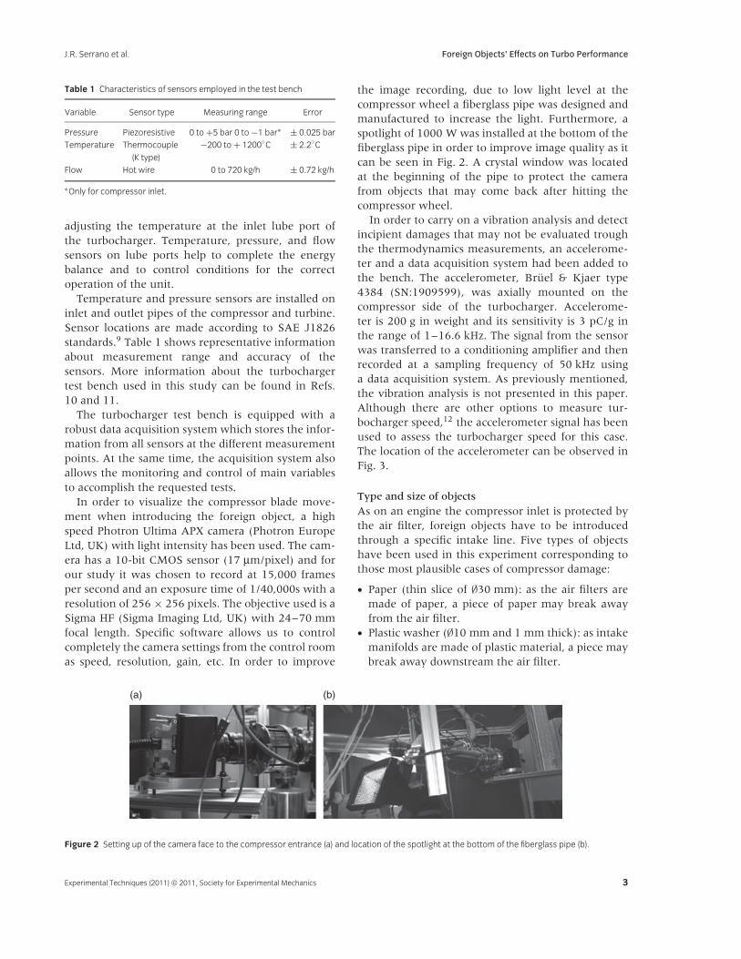
In order to carry on a vibration analysis and detectincipient damages that may not be evaluated troughthe thermodynamics measurements, an accelerome-ter and a data acquisition system had been added tothe bench. The accelerometer, Bruel & Kjaer type4384 (SN:1909599), was axially mounted on thecompressor side of the turbocharger. Accelerome-ter is 200 g in weight and its sensitivity is 3 pC/g inthe range of 1–16.6 kHz. The signal from the sensorwas transferred to a conditioning amplifier and thenrecorded at a sampling frequency of 50 kHz usinga data acquisition system. As previously mentioned,the vibration analysis is not presented in this paper.Although there are other options to measure tur-bocharger speed,12 the accelerometer signal has beenused to assess the turbocharger speed for this case.The location of the accelerometer can be observed inFig. 3.
Type and size of objects
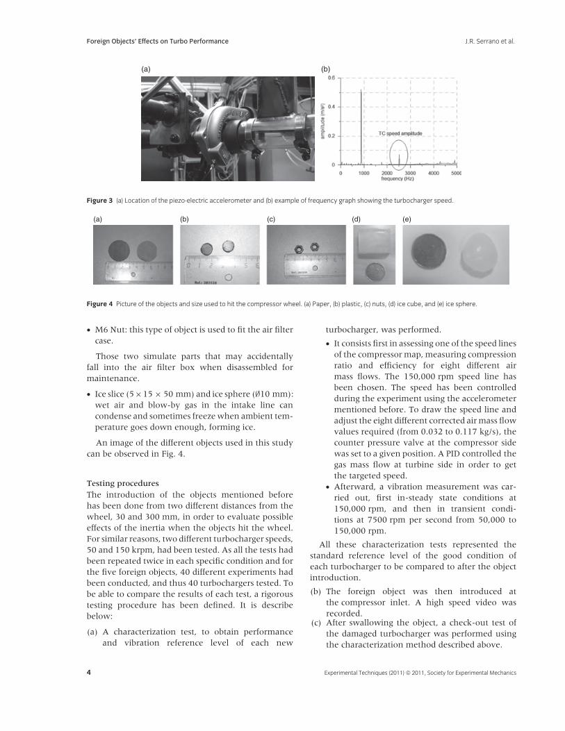
As on an engine the compressor inlet is protected bythe air filter, foreign objects have to be introducedthrough a specific intake line. Five types of objectshave been used in this experiment corresponding tothose most plausible cases of compressor damage:
• Paper (thin slice of ∅30 mm): as the air filters aremade of paper, a piece of paper may break awayfrom the air filter.
• Plastic washer (∅10 mm and 1 mm thick): as intakemanifolds are made of plastic material, a piece maybreak away downstream the air filter.
(a) (b)
Figure 2 Setting up of the camera face to the compressor entrance (a) and location of the spotlight at the bottom of the fiberglass pipe (b).
Experimental Techniques (2011) © 2011, Society for Experimental Mechanics 3
Foreign Objects’ Effects on Turbo Performance J.R. Serrano et al.
(a) (b)
Figure 3 (a) Location of the piezo-electric accelerometer and (b) example of frequency graph showing the turbocharger speed.
(a) (b) (c) (d) (e)
Figure 4 Picture of the objects and size used to hit the compressor wheel. (a) Paper, (b) plastic, (c) nuts, (d) ice cube, and (e) ice sphere.
• M6 Nut: this type of object is used to fit the air filtercase.
Those two simulate parts that may accidentallyfall into the air filter box when disassembled formaintenance.
• Ice slice (5×15 × 50 mm) and ice sphere (∅10 mm):wet air and blow-by gas in the intake line cancondense and sometimes freeze when ambient tem-perature goes down enough, forming ice.
An image of the different objects used in this studycan be observed in Fig. 4.
Testing procedures
The introduction of the objects mentioned beforehas been done from two different distances from thewheel, 30 and 300 mm, in order to evaluate possibleeffects of the inertia when the objects hit the wheel.For similar reasons, two different turbocharger speeds,50 and 150 krpm, had been tested. As all the tests hadbeen repeated twice in each specific condition and forthe five foreign objects, 40 different experiments hadbeen conducted, and thus 40 turbochargers tested. Tobe able to compare the results of each test, a rigoroustesting procedure has been defined. It is describebelow:
(a) A characterization test, to obtain performanceand vibration reference level of each new
turbocharger, was performed.
• It consists first in assessing one of the speed linesof the compressor map, measuring compressionratio and efficiency for eight different airmass flows. The 150,000 rpm speed line hasbeen chosen. The speed has been controlledduring the experiment using the accelerometermentioned before. To draw the speed line andadjust the eight different corrected air mass flowvalues required (from 0.032 to 0.117 kg/s), thecounter pressure valve at the compressor sidewas set to a given position. A PID controlled thegas mass flow at turbine side in order to getthe targeted speed.
• Afterward, a vibration measurement was car-ried out, first in-steady state conditions at150,000 rpm, and then in transient condi-tions at 7500 rpm per second from 50,000 to150,000 rpm.
All these characterization tests represented thestandard reference level of the good condition ofeach turbocharger to be compared to after the objectintroduction.
(b) The foreign object was then introduced atthe compressor inlet. A high speed video wasrecorded.
(c) After swallowing the object, a check-out test ofthe damaged turbocharger was performed usingthe characterization method described above.
4 Experimental Techniques (2011) © 2011, Society for Experimental Mechanics

J.R. Serrano et al. Foreign Objects’ Effects on Turbo Performance
(a) (b)
Figure 5 (a) Manual valve for the introduction of the foreign objects and (b) pneumatic valve controlled from the test room control area.
Figure 6 General view of the testing facility.
Before switching to a new turbo, a completecheckout of the compressor intake line was carriedout in order to guarantee that no air leakages mayaffect the results of the measurements. The check-outtest was made using an ultrasonic leakage detector(AccuTrack VPE, Superior Signal Co., Spotswood, NJ).
Object introduction system
For security reasons, a specific object introductionsystem was designed (Fig. 5). This system is composedof two valves and an intermediate chamber: a manualvalve through which the object is introduced tothe intermediate chamber and closed after that anda pneumatic valve, controlled from the test roomcontrol area, to let the object fall in the intake line ofthe compressor when on demand.
Figure 6 represents a general view of the testingfacility; the turbocharger is located in the center.
Turbocharger data and test matrix
Only one model of turbocharger had been used inthis analysis. Its main characteristics are presented inTable 2.
Table 3 presents the test matrix of this study takinginto account the three considered variables: type of
Table 2 Main turbocharger characteristics
Turbine Compressor General
Type: fixed geometry
turbine (FGT)
Suction ∅37 mm Minimum oil pressure:
0.05 MPa at idlingSuction ∅28 mm Discharge ∅36 mm Minimum oil pressure:
0.1 MPa at full loadDischarge ∅38 mm Wheel ∅41 mm Maximum rotor speed:
247,000 rpmWheel ∅35 mm Maximum
recommended
temperature inlet
60◦CMaximum temperature
at turbine inlet:
760◦C
Maximum
recommended
temperature outlet
180◦C
foreign object, turbocharger speed when introduced,and distance from which the object is introduced.
Results
This section presents the results obtained for thedifferent tests performed.
Characterization tests
As it has been said, in the characterization tests, itwas calculated compressor efficiency and compressionratio from measured variables (SAE9and CIMAC13
standards have been followed in the calculation)for each new turbocharger at different correctedair mass flows. Figure 7 presents typical results forcharacterization test on a specific turbocharger.
In order to check the repetitiveness of thetests and that no measurement problem appeared,each new turbocharger data was added to ageneral graph. The deviation obtained for eachmeasurement was computed. In one case, forexample, this led to detect an abnormal behaviorof the fifth turbocharger measured. Investigationsrevealed leakages at the compressor inlet duct.
Experimental Techniques (2011) © 2011, Society for Experimental Mechanics 5

Foreign Objects’ Effects on Turbo Performance J.R. Serrano et al.
Table 3 Test matrix
Turbocharger No. Object Speed (krpm) Distance (mm)
PaperT3 50 30T4 50 30T5 150 30T6 150 30
PlasticT7 50 30T8 50 30T9 150 30T10 150 30
NutT11 50 30T12 50 30T13 150 30T14 150 30
Ice CubeT15 50 30T16 50 30T17 150 30T21 150 30
Ice SphereT18 50 30T19 50 30T20 150 30T23 150 30
PaperT24 50 300T32 50 300T25 150 300T33 150 300
PlasticT26 50 300T34 50 300T27 150 300T35 150 300
NutT28 50 300T42 50 300T29 150 300T44 150 300
Ice CubeT30 50 300T40 50 300T31 150 300T41 150 300
Ice SphereT36 50 300T38 50 300T37 150 300T39 150 300
Taking into account this situation, a leakage detectioninspection was developed and incorporated to thetesting procedures for the subsequent experiments.
When no problem occurs, the dispersion overmeasurements in a group of different turbochargerstested is low (Figs. 8 and 9) and, as may be observed
Figure 7 T15 compressor efficiency and compression ratio data from
characterization.
Figure 8 Efficiency characterization measurements for different
turbochargers.
on the efficiency measurements, the dispersionincreases with the air mass flow.
Additionally, a statistical analysis was performed onthe compression ratio and the compressor efficiency.The normality of the statistics has been verified asillustrated in Figs. 10 and 11.
Table 4 summarizes the characterization statisticsvalues. The testing configuration used to introducethe foreign objects 30 mm far from the compressorwheel has an impact on the global efficiency as aconsequence of the disturbance in air inlet flowgenerating a negative effect that reduces the efficiencyas attested by the measurements.
Foreign objects introduction
The high speed camera helped to understand theeffects of the foreign objects ingestion. Some snap
6 Experimental Techniques (2011) © 2011, Society for Experimental Mechanics

J.R. Serrano et al. Foreign Objects’ Effects on Turbo Performance
Figure 9 Compression ratio characterization measurements for differ-
ent turbochargers.
Figure 10 Normal probability plot for efficiency results of turbochargers
on test performed from 300 mm.
Figure 11 Histogram plot for compression ratio results of turbo-
chargers on test performed from 30 mm.
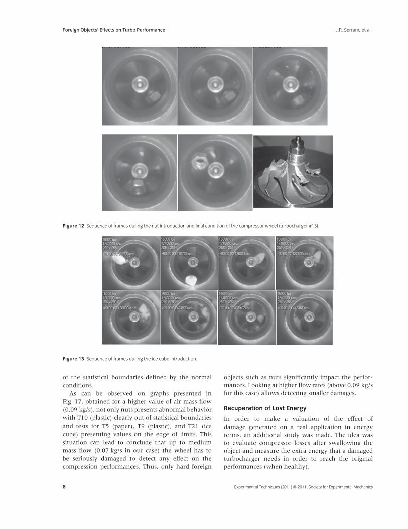
shots are reproduced in Fig. 12 (nut) and in Fig. 13(ice cube). The repetitive hits of the nut over thecompressor wheel lead to a progressive severe damage
Table 4 Main statistical results for characterization test (maximum
efficiency point)
Distance
(30 mm)
Distance
(300 mm)
Efficiency Average 76.7% 78.0%Standard deviation 0.4 0.8Confidence Interval ± 0.2 ± 0.4Distribution fitting Normal
distribution
Normal
distributionCompression
ratio
Average 1.65 1.66
Standard deviation 0.02 0.01Confidence interval ± 0.0 ± 0.0Distribution fitting Normal
distribution
Normal
distribution
of the blades. The inspection of the compressordisassembled confirmed the video recorded.
In Fig. 13, the snap shots witness the destruction ofthe ice cube, rather than the milling of the compressorwheel. The final condition of the compressor wheeldoes not show any appreciable damage.
Check-out test
In most of the tests performed, the object wasswallowed by the compressor. The measurement ofthe compressor efficiency and compression ratio couldthen be performed without any disassembling.
The nuts tests were stopped before swallowingthe nuts because the wheels were already clearlydamaged. It is impossible and pointless to assess howlong the test should last to swallow the nut. It is justobvious that the longer the nuts mills the wheel, andthe faster the wheel speeds, the more severe is thedamage as shown in Fig. 14.
Individual check-out results had been comparedthe corresponding characterization tests. The nutsled to the most severe damages. Figure 15 presentsthe results obtained for the turbocharger T13.An important deviation from characterization maybe observed. It was necessary to disassemble thecompressor housing to remove the nut beforemeasuring the thermodynamics parameters again.
For a selected air mass flow (here 0.068 kg/s cor-responding to the maximum efficiency), the graphspresented in Fig. 16 summarize the measurementsof all the compressor performances after swallow-ing foreign objects. Dot lines represent the char-acterization performances (mean ± 2sigma), so itis easy to identify which tests led to significantdamages.
As can be observed on graphs presented in Fig. 16,the nut tests show performances significantly out
Experimental Techniques (2011) © 2011, Society for Experimental Mechanics 7
Foreign Objects’ Effects on Turbo Performance J.R. Serrano et al.
Figure 12 Sequence of frames during the nut introduction and final condition of the compressor wheel (turbocharger #13).
Figure 13 Sequence of frames during the ice cube introduction.
of the statistical boundaries defined by the normalconditions.
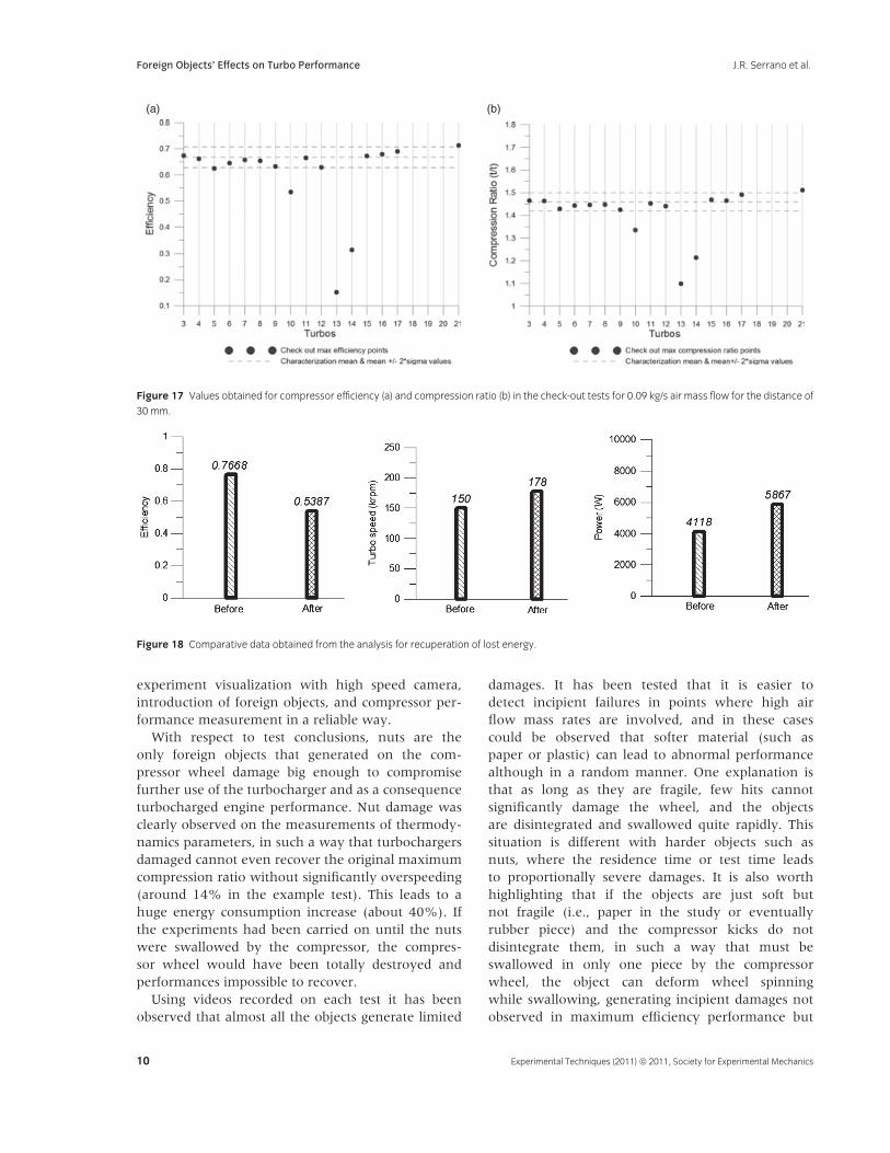
As can be observed on graphs presented inFig. 17, obtained for a higher value of air mass flow(0.09 kg/s), not only nuts presents abnormal behaviorwith T10 (plastic) clearly out of statistical boundariesand tests for T5 (paper), T9 (plastic), and T21 (icecube) presenting values on the edge of limits. Thissituation can lead to conclude that up to mediummass flow (0.07 kg/s in our case) the wheel has tobe seriously damaged to detect any effect on thecompression performances. Thus, only hard foreign
objects such as nuts significantly impact the perfor-mances. Looking at higher flow rates (above 0.09 kg/sfor this case) allows detecting smaller damages.
Recuperation of Lost Energy
In order to make a valuation of the effect ofdamage generated on a real application in energyterms, an additional study was made. The idea wasto evaluate compressor losses after swallowing theobject and measure the extra energy that a damagedturbocharger needs in order to reach the originalperformances (when healthy).
8 Experimental Techniques (2011) © 2011, Society for Experimental Mechanics
J.R. Serrano et al. Foreign Objects’ Effects on Turbo Performance
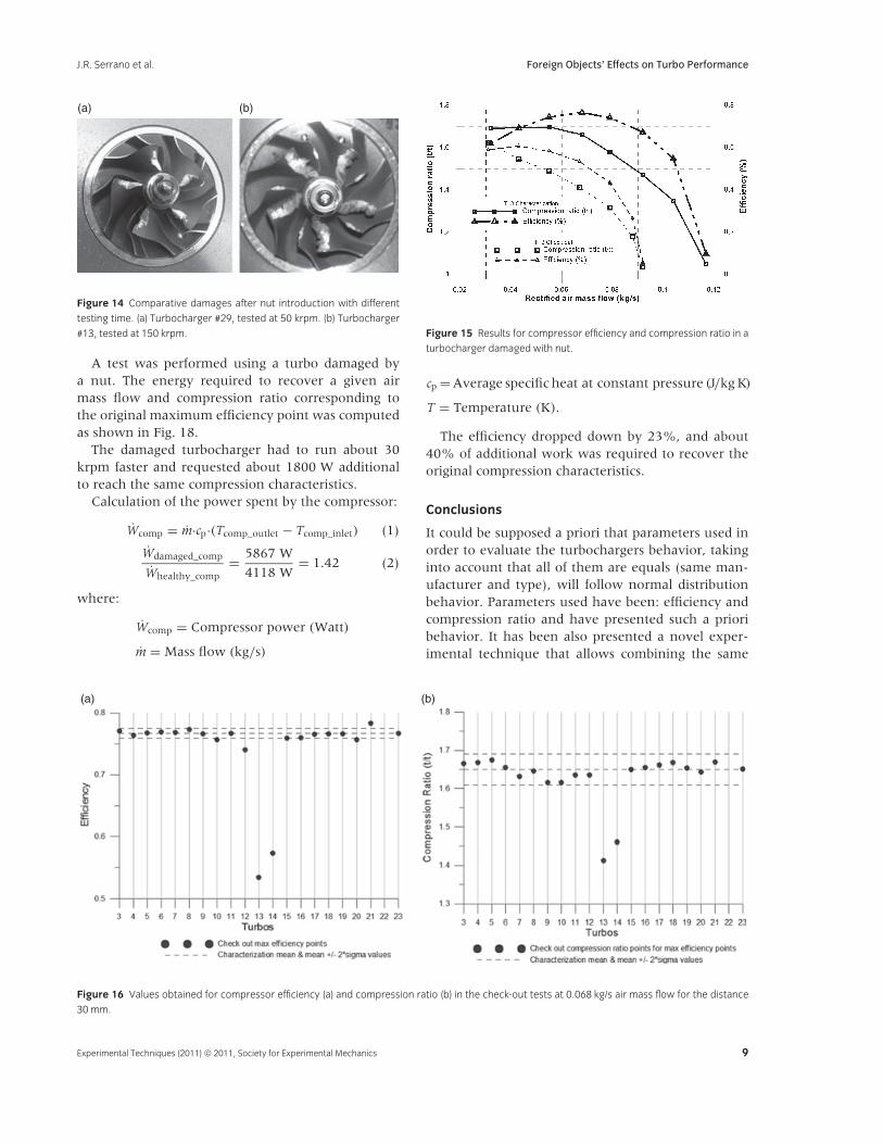
(a) (b)
Figure 14 Comparative damages after nut introduction with different
testing time. (a) Turbocharger #29, tested at 50 krpm. (b) Turbocharger
#13, tested at 150 krpm.
A test was performed using a turbo damaged bya nut. The energy required to recover a given airmass flow and compression ratio corresponding tothe original maximum efficiency point was computedas shown in Fig. 18.
The damaged turbocharger had to run about 30krpm faster and requested about 1800 W additionalto reach the same compression characteristics.
Calculation of the power spent by the compressor:
Wcomp = m·cp·(Tcomp_outlet − Tcomp_inlet) (1)
Wdamaged_comp
Whealthy_comp= 5867 W
4118 W= 1.42 (2)
where:
Wcomp = Compressor power (Watt)
m = Mass flow (kg/s)
Figure 15 Results for compressor efficiency and compression ratio in a
turbocharger damaged with nut.
cp = Average specific heat at constant pressure (J/kg K)
T = Temperature (K).
The efficiency dropped down by 23%, and about40% of additional work was required to recover theoriginal compression characteristics.
Conclusions
It could be supposed a priori that parameters used inorder to evaluate the turbochargers behavior, takinginto account that all of them are equals (same man-ufacturer and type), will follow normal distributionbehavior. Parameters used have been: efficiency andcompression ratio and have presented such a prioribehavior. It has been also presented a novel exper-imental technique that allows combining the same
(a) (b)
Figure 16 Values obtained for compressor efficiency (a) and compression ratio (b) in the check-out tests at 0.068 kg/s air mass flow for the distance
30 mm.
Experimental Techniques (2011) © 2011, Society for Experimental Mechanics 9
Foreign Objects’ Effects on Turbo Performance J.R. Serrano et al.
(a) (b)
Figure 17 Values obtained for compressor efficiency (a) and compression ratio (b) in the check-out tests for 0.09 kg/s air mass flow for the distance of
30 mm.
Figure 18 Comparative data obtained from the analysis for recuperation of lost energy.
experiment visualization with high speed camera,introduction of foreign objects, and compressor per-formance measurement in a reliable way.
With respect to test conclusions, nuts are theonly foreign objects that generated on the com-pressor wheel damage big enough to compromisefurther use of the turbocharger and as a consequenceturbocharged engine performance. Nut damage wasclearly observed on the measurements of thermody-namics parameters, in such a way that turbochargersdamaged cannot even recover the original maximumcompression ratio without significantly overspeeding(around 14% in the example test). This leads to ahuge energy consumption increase (about 40%). Ifthe experiments had been carried on until the nutswere swallowed by the compressor, the compres-sor wheel would have been totally destroyed andperformances impossible to recover.
Using videos recorded on each test it has beenobserved that almost all the objects generate limited
damages. It has been tested that it is easier todetect incipient failures in points where high airflow mass rates are involved, and in these casescould be observed that softer material (such aspaper or plastic) can lead to abnormal performancealthough in a random manner. One explanation isthat as long as they are fragile, few hits cannotsignificantly damage the wheel, and the objectsare disintegrated and swallowed quite rapidly. Thissituation is different with harder objects such asnuts, where the residence time or test time leadsto proportionally severe damages. It is also worthhighlighting that if the objects are just soft butnot fragile (i.e., paper in the study or eventuallyrubber piece) and the compressor kicks do notdisintegrate them, in such a way that must beswallowed in only one piece by the compressorwheel, the object can deform wheel spinningwhile swallowing, generating incipient damages notobserved in maximum efficiency performance but
10 Experimental Techniques (2011) © 2011, Society for Experimental Mechanics

J.R. Serrano et al. Foreign Objects’ Effects on Turbo Performance
present in visualization and at maximum mass flowconditions.
Acknowledgments
The authors wish to thank Spanish Grant TRA2007-65433/TAIR from Ministerio de Educacion y Ciencia.D.G. Investigacion for supporting this work.
References
1. Watson, N., and Janota, M.S., Turbocharging theInternal Combustion Engine. Macmillan, London(1982).
2. Gjika, K., and Larue, G.D., ‘‘Dynamic Behaviour ofRotor-Bearing Systems Involving Two Oil Films inSeries–Application to High-Speed Turbochargers,’’IMechE Conference Transactions C602/021/2002. SeventhInternational Conference on Turbochargers andTurbocharging (2002).
3. Galindo, J., Serrano, J.R., Guardiola, C., andCervello, C., ‘‘Surge Limit Definition in a SpecificTest Bench for the Characterization of AutomotiveTurbochargers,’’ Experimental Thermal and FluidScience 30:449–462 (2006).
4. Engels, B., ‘‘Lifetime Prediction for TurbochargerCompressor Wheels-Why Use Titanium?’’ IMechEConference Transactions C602/037/2002. SeventhInternational Conference on Turbochargers andTurbocharging (2002).
5. Ahdad, F., and Soare, M.A., ‘‘Prediction of Durationof Life of Automotive Components underThermomechanical Fatigue,’’ IMechE ConferenceTransactions C602/020/2002. Seventh InternationalConference on Turbochargers and Turbocharging (2002).
6. Osako, K., Jinnai, Y., Samata, A., Suzuki, H.,Ibaraki, S., and Hayashi, N., ‘‘Development of theHigh-Performance and High-Reliability VGTurbocharger for Automotive Applications,’’Mitsubishi Heavy Industries, Ltd. Technical Review43(3):31–35 (2006).
7. Holmes, R., ‘‘Turbocharger Vibration - A CaseStudy,’’ IMechE Conference Transactions C692/031/2002.Seventh International Conference on Turbochargers andTurbocharging (2002).
8. Zhao, X., He, H., and Xu, S., ‘‘Influence of theFloating-Ring Bearing Parameters on Stability ofTurbocharger Rotor-Bearing System,’’ Proceedings ofthe Fourth International Symposium of Fluid Machineryand Fluid Engineering. Springer ISBN 978-7-302-18788-2, pp. 421–425 (2008).
9. SAE J1826, Turbocharger Gas Stand Test Code,Recommended Practice (1995).
10. Lujan, J.M., Bermudez, V., Serrano, J.R., andCervello, C., ‘‘Test Bench for Turbocharger GroupsCharacterization,’’ SAE Paper 2002-01-0163. doi:10.4271/2002-01-0163.
11. Serrano, J.R., Guardiola, C., Dolz, V., Tiseira, A., andCervello, C., ‘‘Experimental Study of the TurbineInlet Gas temperature influence on TurbochargerPerformance,’’ SAE Paper 2007-01-1559. doi:10.4271/2007-01-1559.
12. Macian, V., Lujan, J.M., Bermudez, V., andGuardiola, C., ‘‘Exhaust Pressure PulsationObservation from Turbocharger InstantaneousSpeed Measurement,’’ Measurement Science andTechnology 15:1185–1194 (2004).
13. The International Council on Combustion Engines(CIMAC), Turbocharging Efficiencies—Definitions andGuidelines for Measurements and Calculation (2007).
Experimental Techniques (2011) © 2011, Society for Experimental Mechanics 11