STUDY OF PLC AND ITS APPLICATION IN A SMART TRAFFIC ...ethesis.nitrkl.ac.in/5153/1/109EI0319.pdf ·...
40
1 | Page STUDY OF PLC AND ITS APPLICATION IN A SMART TRAFFIC CONTROL SYSTEM A THESIS SUBMITTED IN PARTIAL FULFILLMENT OF THE REQUIREMENTS FOR THE DEGREE OF Bachelor of Technology in Electronics & Instrumentation Engineering By Rohan Dutta Rupak Das 109EI0138 109EI0319 Department of Electronics & Communication Engineering National Institute of Technology Rourkela-2012-2013
Transcript of STUDY OF PLC AND ITS APPLICATION IN A SMART TRAFFIC ...ethesis.nitrkl.ac.in/5153/1/109EI0319.pdf ·...

1 | P a g e
STUDY OF PLC AND ITS APPLICATION IN A
SMART TRAFFIC CONTROL SYSTEM
A THESIS SUBMITTED IN PARTIAL FULFILLMENT OF THE REQUIREMENTS FOR THE
DEGREE OF
Bachelor of Technology in
Electronics & Instrumentation Engineering
By
Rohan Dutta Rupak Das
109EI0138 109EI0319
Department of Electronics & Communication Engineering
National Institute of Technology
Rourkela-2012-2013

2 | P a g e
STUDY OF PLC AND ITS APPLICATION IN A
SMART TRAFFIC CONTROL SYSTEM
A THESIS SUBMITTED IN PARTIAL FULFILLMENT OF THE REQUIREMENTS FOR THE
DEGREE OF
Bachelor of Technology in
Electronics & Instrumentation Engineering
Under the guidance of:Prof Tarun Kumar Dan
By
Rohan Dutta Rupak Das
109EI0138 109EI0319
Department of Electronics & Communication Engineering
National Institute of Technology
Rourkela-2012-2013

3 | P a g e
NATIONAL INSTITUTE OF TECHNOLOGY,ROURKELA
CERTIFICATE
This is to certify that the project work titled “STUDY OF PLC AND ITS
APPLICATION IN A SMART TRAFFIC CONTROL SYSTEM” submitted by
Rohan Dutta(109EI0138) & Rupak Das(109EI0319) for the award of
Bachelor of Technology Degree in Electronics and Instrumentation
Engineering for the session 2009-2013 at National Institute of
Technology, Rourkela is an authentic work carried out by them under
my supervision and guidance.
Date Prof. T.K DAN
Department of Electronics & Communication
N.I.T Rourkela
Rourkela,769008

4 | P a g e
ACKNOWLEDGEMENT
We would like to express our gratitude and sincere thanks to our
respected supervisor Prof. Tarun Kumar Dan for his guidance,
motivation and support he has provided throughout the course of this
work. We would like to thank all the faculty members and staff of the
Department of Electronics and Communication Engineering, N.I.T.
Rourkela for their help throughout the course.
Rohan Dutta Rupak Das
109EI0138 109EI0319

5 | P a g e
CONTENTS PAGE
CERTIFICATE 3
ACKNOWLEDGEMENT 4
ABSTRACT 8
1 PLC 9
1.1 INTRODUCTION 9
1.2 OPERATION OF PLC 9
1.3 BASIC PLC SCHEMA 10
1.4 LSM CONTROLLER 12
2 APPLICATIONS OF PLC 16
2.1 PACKAGING INDUSTRY 17
2.2 CONTROLLING THE PRESSURE IN A PROCESS PLANT 18
3 TRAFFIC CONTROL SYSTEM 19
3.1 OVERVIEW 19
3.2 BRIEF HISTORY 20

6 | P a g e
3.3 ADVANTAGES OF A GOOD TRAFFIC CONTROL SYSTEM 21
4 SMART TRAFFIC CONTROL 22 4.1 INTRODUCTION 22 4.2 NEED FOR A SMART TRAFFIC CONTROL 22 4.3 MODES OF WORKING 23 4.4 PRACTICAL DESIGN 25
5 PROTOTYPE HARDWARE 26 5.1 HARDWARE COMPONENTS USED 26 5.2 ATMEGA16 26 5.3 IC7805 27 5.4 POTENTIOMETER 28 5.5 CIRCUIT 29
6 SOFTWARE IMPLEMENTATION 30 6.1 AVR STUDIO 4.0 30 6.2 CODE IMPLEMENTED 30 6.3 LADDER LOGIC CONCEPT 37 6.4 LADDER LOGIC FOR SMART TRAFFIC CONTROLLER
37
RESULTS AND DISCUSSION
39
REFERENCES 40

7 | P a g e
LIST OF FIGURES PAGE
1.1 Operation of PLC 10
1.2 Overview of PLC 11
1.3 LSM Controller 12
1.4 Conveyor belt 13 1.5 AC Synchronous Motor 13 1.6 Single Acting Cylinder 14 1.7 Capacitive Sensors 14
4.1 Smart Traffic Light Model 25 5.1 Pin diagram of ATMEGA16 27 5.2 IC7805 28 5.3 Potentiometer 28
5.4 Overall circuit diagram of Smart Traffic Control 29 6.1 Ladder logic diagram of Smart Traffic Control 30

8 | P a g e
ABSTRACT
PLC or Programmable logic controller was used to control a
mechantronics system using specific functions.Basic PLC functions such
as timing,sequencing,controlling and relaying were implemented.The
basic programming logic and ladder programming was studied and
implemented.The intelligent or “Smart Traffic Control” is one which
would be able to calculate the vehicle density in a lane at a 4-way
crossing and then decide the priority automatically using a program
burned in microcontroller.
In practical situations sensors are used to
detect presence of vehicles in a lane and calculate the density and sends
an interrupt signal to the control unit .In PLC the status of the sensors
are checked and certain logical operations are performed to decide
which lane is to be serviced first.Under low density condition it would
operate sequentially.Ladder diagram was developed for the
implementation of the same in PLC.
9 | P a g e
1. PLC
1.1 INTRODUCTION
Over time control system engineering has evolved greatly.In the past manual
control was the only the form of control.More recently electrical control based on
relays were used.These relays allow switching of power without a mechanical
switch.PLC or a programmable logic controller is used to check and control a
system using digital inputs which can be programmed for automation.The growth
of PLC started in 1970s.The PLCs have become a major component of factory
mainly because of the advantages they offer like
Cost effective control for complete system
Flexible and reusable
Compuatational abilities
Analytical power and decision making
PLCs are available in different designs or formats which vary in the type of their
inputs and outputs and the software used for programming.
1.2 OPERATION OF PLC
CHECKING THE INPUT STATUS- PLC takes a look at each input todetermine whether it is on or off condition. EXECUTING THE PROGRAM-PLC executes a program by oneinstruction at a time. If the first input is on then it should turn on the first output.Since it is already

10 | P a g e
known, it should be able to decide whether the first output shouldbe turned on based on the state of the first input. It will store the execution resultsfor use later during the next step. UPDATING OUTPUT STATUS-In the end PLC updates the status of the outputs based on which inputs are on during the first step andthe results of executing your program during the second step.
Fig1.1 Operation of PLC
1.3 BASIC PLC schema
The basic PLC schema includes memory,CPU, power supply, input block, output block, communication and expansion connections. Figure 1.2 shows the PLC system overview.
CPU modules - The Central Processing Unit (CPU) Module is the brain of the PLC and is used to read inputs, execute the control programs and update the outputs. The CPU consists of a arithmetic logic unit (ALU), timing and control circuitry, accumulator,address stacks,program counter and instructionregisters. A PLC works by continuously scanning a program. Memory - The memory includes pre-programmed ROM containingPLC’s operating system, driver program, application programs and RAM . PLC manufacturers offer different types of retentive memory to saveuser programs and data while power

11 | P a g e
is cut-off, so that the PLC can resume execution of the control program as soon as power is restored. I/O Modules –The input and output (I/O) modules connect the PLC to the sensors and actuators and provide isolation for the low-voltage, low-current signals thatthe PLC uses internally from electrical circuits required bymost sensors and actuators. A wide range of I/O modules are available including:digital (logical) I/O modules and analog(continuous) I/O modules.
Fig1.2 Overview of PLC

12 | P a g e
1.4 LSM CONTROLLER LSM or linear synchronous motion controller is a mechatronics system having different components such as X-Y table,rotary table,conveyor belt,motors,sensors,actuators,single and double acting cylinders which are controlled by programming in Control X software. The specifications of the LSM controller used by us are:
Operating Voltage: 24 VDC
Inputs: sixteen Opto-Isolated digital inputs
Windows software ControlX
Outputs: 8 Relayed digital inputs
Programming: Statement/Instruction
Operator interface: Display - Windows based high resolution interface
Plug & Play operation
Fig1.3 LSM Controller
13 | P a g e
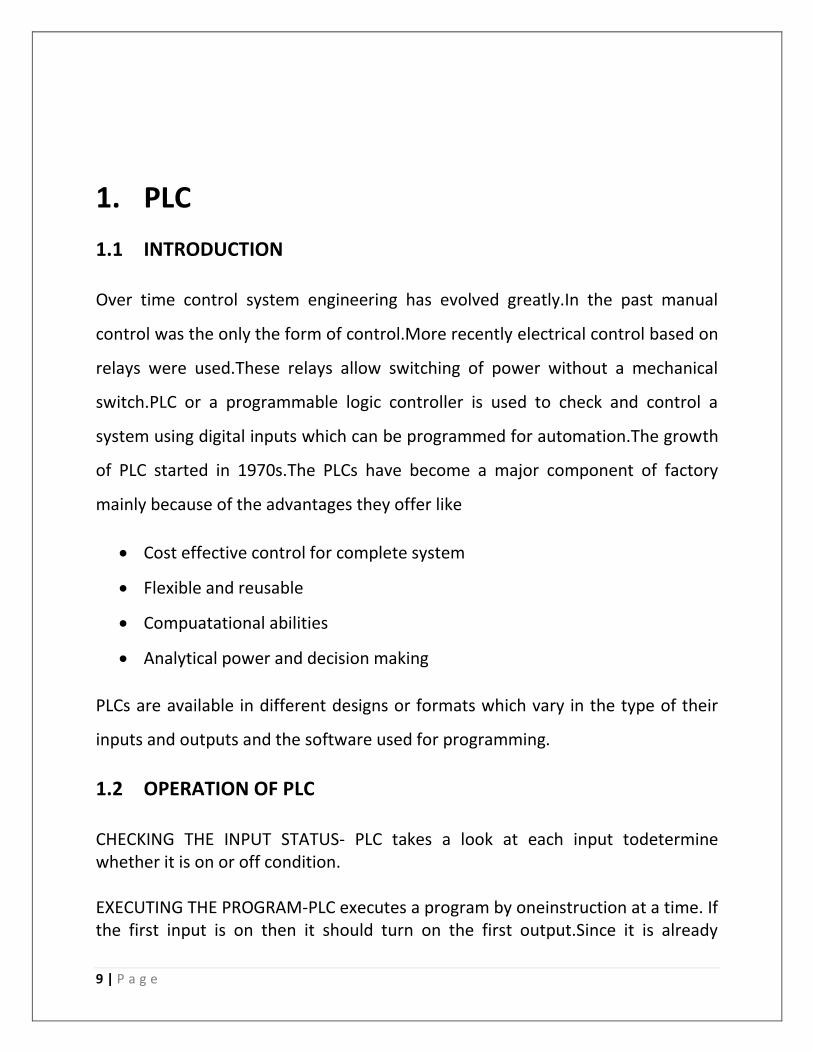
Fig1.4 Conveyor Belt
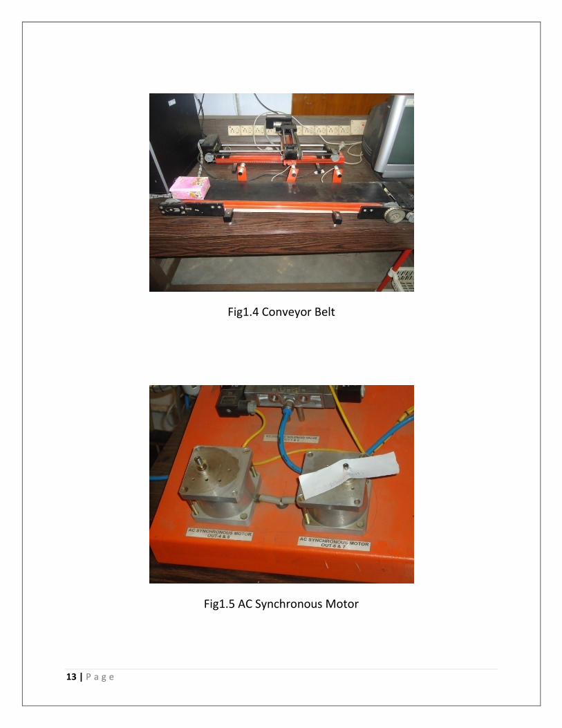
Fig1.5 AC Synchronous Motor

14 | P a g e
Fig1.6 Single Acting Cylinder
Fig1.7 Capacitive Sensors

15 | P a g e
Some commonly used commands in Control X Software
OUTPUT COMMAND:
To turn “ON” or “OFF” the Output of LSM Controller Package PLC command is:
set_output (Output Address, Status of the Output )
TO DELAY THE OPERATIONS:
Delay(TIME PERIOD)
TO SET THE POSITION OF AXIS
set_pos output adress,no of pulses or interval
TO SET THE VELOCITY AND ACCELERATION
set_vel (output adress,velocity)
set_acc (output adress,acceleration)

16 | P a g e
2. APPLICATIONS OF PLC
Problem Statements solved using Control X on LSM Controller
(a) An AC synchronous motor was controlled by operating it in clockwise and
anti-clockwise direction in manual mode. In programming time delay and loop
operation were performed.
For i=1 to 10
Set_output 4,1
Delay(3000)
Set_output 4,0
Delay(3000)
Set_output 5,1
Delay(3000)
Set_output 5,0
Next
(b)It was required to control single acting spring return cylinder and double
acting cylinder in manual mode. Speeds of pistons of both cylinders were
adjustable. In Programming time delay and loop operations were performed.
For 1=1 to 10
Set_output 3,1 #single acting cylinder
Set_output 4,1 #double acting cylinder
Delay(3000)
Set_output 3,0
Set_output 4,0
Set_output 5,1
Delay(3000)
Set_output 5,0
Next
17 | P a g e
2.1 A PLC design for operation in an automated packaging plant
For i=1 to 5
Set_open 2,200
Dowhile get_input(15)=0
Loop
Stop_axis 2
Set_output 6,1
Delay 3000
Set_output 6,0
Delay 1000
Set_output 7,1
Delay 3000
Set_output 7,0
Set_open 2,200
Dowhile get_input(14)=0
Loop
Stop_axis 2
Set_output 5,1
Delay 3000
Set_output 5,0
Delay 1000
Set_output 4,1
Delay 3000
Set_output 4,0
Set_open 2,200
Next
Here we have used AC synchronous motors and conveyor beltfor operation.In a
bottle packaging industry the bottles are arranged in a given order at regular
intervals.The conveyor belt moves and hence the bottle moves

18 | P a g e
forward.Whenever it reaches a designated point a photo-electric sensor detects
its presence and sends an interrupt signal.Whenever filling up or packaging is
required there is a delay operation which stops the conveyor belt for a brief
period and activates the motors in clockwise or anticlockwise direction as desired
using different commands in Control X software.The program was run and results
were observed on the PLC hardware.
2.2 A PLC design for controlling the pressure of a pump
Set_output 3,1
Dowhile get_input(4)=0
Loop
Set_output 6,1
Delay 3000
Set_output 6,0
Delay 1000
Set_output 7,1
Delay 3000
Set_output 7,0
Next
Here we used specified Control X commands for operating the the
operation of a single-acting cylinder.It is used mainly for the purpose of
venting out excess pressure in a process plant.The main principle is that
whenever a pressure above the threshold value is detected the
synchronous motors open up the venting chamber and hence release the
excess pressure.Once pressure gets back to normal level the motor once
again closes the venting chamber.

19 | P a g e
3. TRAFFIC CONTROL SYSTEM
3.1 Overview
Traffic Control Systems are used at a point where there are more than two paths
for passage of vehicles or wherever passage is to be given to pedestrians to cross
a road.It is also used wherever two paths cross each other thus creating a four-
way lane.These systems are also put in place at points where there are by-lanes
attached to the main road.The main aim of a traffic control system is to control
the flow of vehicles through a lane and prevent accidents or road blockage.These
systems are also used at points wherever a vehicle needs to be stopped for any
purpose.
In our country the traffic control system is mostly based on sequential
logic.There are three lights red for stop,yellow for get ready and green for go.Each
light operates for a given period one after the other.The programming is so done
that two lanes won’t have the green light at the same time.
The traffic control system at a certain places are even controlled manually by
traffic personnel but human error calls for automation to prevent undesirable
incidents on road.
The traffic signals control the vehicle movements.they are connected to
electronics system which control the signals.They mainly work on logics which can
be classified as
a. signal phase and cycle length which is dependent on the traffic flow on the
desired tracks.
b. system responds to interrupts or timing based system and open the desired
signal as required

20 | P a g e
3.2 Brief History
J. P. Knight created the first traffic signal which was developed in London,
England in 1868.
The modern traffic light was invented in America. New York had installed a
three color system in 1918 which was operated manually from a tower in
the middle of the street.
In 1923 Garrett Morgan patented an electric traffic light system using a
pole with a cross section on which the words STOP and GO were
illuminated.
In 1926 , first automatic signals were installed in London; they depended
on a timer to activate them.
A better idea was the inductive-loop device: a loop of wire was embedded
in the road and connected to a box controlling lights; a current of
electricity passes through the loop, and when the steel body of cars passed
over, it produced a light activating signal .
In the current scenario in some countries, traffic is automatically routed
onto limited access highway by the help of computer activated guidance
systems that calculate traffic volume on thehighway. Global positioning
satellite system (GPS) is installed in many cars.These systems link with a
satellite and inform drivers what are the possible routes to their
destination. Such systems eventually enable the drivers to determine the
best route to a destination under prevailing traffic conditions thus
optimizing time.

21 | P a g e
3.3 Advantages of a good Traffic Control System
A properly ordered traffic control system can
1. Provide for orderly movement of traffic
2. Increase capacity at intersection
3. Reduce frequency and severity of certain kind of clashes
4. Provide continuous movement of traffic at a desired speed
5. Interrupt heavy traffic to allow pedestrians to pass
6. Effectively perform traffic management
But using a generalized traffic control system fails to detect high priority
situations or emergency conditions.Hence the need for a Smart Traffic Control
System arises which would work on certain conditions and be able to take
decisions automatically.

22 | P a g e
4. SMART TRAFFIC CONTROL SYSTEM
4.1 Introduction
A Smart Traffic Control System automizes the traffic control activity and uses
certain logical and mathematical operations and derives priority order of the
lanes based on certain factors and hence controls the traffic in an optimized
manner.It uses inputs from sensors and sends interrupt signals to the controlling
unit which in turn handles the operation of traffic signals automatically.
4.2 Need for Smart Traffic Control
Increasing number of vehicles and lower phase of highways developments
have led to traffic congestion problem.
Time of travel, environment quality, quality of life and road safety are all
adversely affected as a result of traffic congestions.
Delays caused due to traffic congestions indirectly affect productivity,
efficiency, and energy losses.
Human error can cause mismanagement.
Emergency situations like medical emergencies,costruction
work,accidents,etc

23 | P a g e
4.3 Modes of operation
Traffic load is dependent on factors such as time,day,season ,weather and
unpredictable situations like accidents or construction activity or any special
event.
Traffic control system can be broadly classified as
Saturated-:Aim to serve as many drivers as possible
Unsaturated-:Reduces mean delay for drivers
An adaptive control system must be able to diagnose the saturation condition
and be able to change the objective function .The main aim of this project is to
minimize waiting time for each lane as well as serving the busy lanes as much as
possible
The system can be divided into four main parts-:
Hardware Model
Programming
Sensors
PLC
The objective is to build a prototype that has the ability to collect information of
the busy tracks by sensors and using a control unit to shift service to a given lane
as per priority.

24 | P a g e
An intelligent traffic system works in four different modes
1. Normal flow
2. Peak flow
3. Off time
4. Manual operation
Normal flow occurs when the traffic in a lane is less than a certain fixed threshold
value.In this time the traffic signals operate sequentially.
Peak time is the period in which the traffic density crosses the threshold value in
a given lane and that lane gets service irrespective of its sequence.
Manual operation involves closing of lanes and opening of lanes manually in case
of an emergency or for allowing pedestrians to pass through.
The design operation should be such that every lane gets service after certain
amount of time.
In a practical design inductive loops are used as sensors to detect the presence of
vehicles at intersections.Its basic function is to provide interrupts to control
units.It has two parts – a coil and a detector unit.Coil is main part of the sensor
and consists of more loops of wire embedded in the pavement.Inductive coil is
connected to the detector unit which is an electronic circuit.When vehicles pass
over or rest on the loop then due to induction more current flows through the
loop and this causeschange in frequency.Detector unit detects these signals and
then send an interrupt signal to the control unit.
In the prototype hardware that we have used we have implemented
potentiometers to vary the density and outputs are connected to a
microcontroller which sends it to its control unit to operate the LEDs.

25 | P a g e
4.4 Practical Design
In a practical design inductive loops are used as sensors to detect the presence of
vehicles at intersections.Its basic function is to provide interrupts to control
units.It has two parts,coil and a detector unit.Coil is main part of sensor and
consists of more loops of wire embedded in the pavement.Inductive coil is
connected to the detector unit which is an electronic circuit.When vehicles pass
over or rest on the loop then due to induction more current flows through the
loop and this causes change in frequency.Detector unit can detect these signals
and then sends an interrupt signal to the control unit for further operation.
Fig4.1 Smart Traffic Light Model

26 | P a g e
5. PROTOTYPE HARDWARE
5.1 Hardware components used
For our prototype we designed a circuit and implemented it in hardware and
program was burned in order to make it operational.
The basic hardware components that have been used are
ATMEGA16(Microcontroller)
IC7805(Voltage Regulator)
LEDs
Potentiometer
Resistors(330KΩ)
Capacitor
5.2 ATMEGA16
It is a 8-bit AVR microcontroller with 16Kb in system programmable flash.It has
32×8 general purpose registers,512bytes of EEPROM,1KB of internal SRAM and
JTAG cable.It has peripheral features like two 8-bit timers/counters,one16-bit
timer and a comparator/prescaler. It has 32 programmable I/O lines divided into
four ports,PORT A,PORT B,PORT C and PORT D.It has pins for VCC,Gnd
voltage,RESET and clock.It has a speed grade of 0-8 MHz.
The programming was done using a programmer and Sinaprog.exe and a code
was burned into the microcontroller.

27 | P a g e
Fig5.1 Pin Diagram of ATMEGA16
5.3 IC7805
It is a voltage regulator.It converts a 12V input from adapter to a regulated
voltage of 5V.
It has 3 pins
1. Input Voltage(5-18V)
2. Gnd(0V)
3. Output Voltage(5V)

28 | P a g e
Fig5.2 IC7805 Pin Configuration
5.4 POTENTIOMETER
It is a three terminal resistor with a sliding contact that forms an adjustable
voltage divider.Here it has been used in place of sensors for density detection in
the lanes.The three terminals are
1. VCC
2. Gnd
3. Connected to ADC pin of ATMEGA16
Fig5.3 Potentiometer

29 | P a g e
5.5 CIRCUIT
Fig5.4 Overall circuit Diagram of Smart Traffic Control

30 | P a g e
6.SOFTWARE IMPLEMENTATION
6.1 AVR STUDIO 4.0
AVR Studio 4.0 is an integrated development platform (IDP) for developing and
debugging Atmel AVR microcontroller applications.It gave us seamless and easy-
to-use environment to write, build and debug our applications written in C/C++ or
assembly code. Atmel Studio 4.0 supports all 8 & 32 bit AVR, SoC wireless family,
SAM3 and SAM4 microcontrollers, and connects easily to Atmel debuggers and
development kits.
6.2 CODE
#include<avr/io.h>
#include<util/delay.h>
#include<avr/adc.h>
#define L1 500
#define L2 500
#define L3 500
#define L4 500
#define LG1 PC0
#define LR1 PC1
#define LG2 PC2
#define LR2 PC3
#define LG3 PC4
#define LR3 PC5
#define LG4 PC6
#define LR4 PC7
void main(void)
DDRB=0xff;
DDRC=0xff;
DDRD=0xff;
adc_init();
int ln1,ln2,ln3,ln4;

31 | P a g e
while(1)
ln1=read_adc_channel(0);
ln2=read_adc_channel(1);
ln3=read_adc_channel(2);
ln4=read_adc_channel(3);
if(ln1<255)
PORTB&=0xf0;
PORTB|=0x01;
else if(ln1<510)
PORTB&=0xf0;
PORTB|=0x03;
else if(ln1<765)
PORTB&=0xf0;
PORTB|=0x07;
else
PORTB&=0xf0;
PORTB|=0x0f;
if(ln2<255)
PORTB&=0x0f;
PORTB|=0x10;
else if(ln2<510)
PORTB&=0x0f;
PORTB|=0x30;
else if(ln2<765)
PORTB&=0x0f;
PORTB|=0x70;
else
PORTB&=0x0f;

32 | P a g e
PORTB|=0xf0;
if(ln3<255)
PORTD&=0xf0;
PORTD|=0x01;
else if(ln3<510)
PORTD&=0xf0;
PORTD|=0x03;
else if(ln3<765)
PORTD&=0xf0;
PORTD|=0x07;
else
PORTD&=0xf0;
PORTD|=0x0f;
if(ln4<255)
PORTD&=0x0f;
PORTD|=0x10;
else if(ln4<510)
PORTD&=0x0f;
PORTD|=0x30;
else if(ln4<765)
PORTD&=0x0f;
PORTD|=0x70;
else
PORTD&=0x0f;
PORTD|=0xf0;
if(ln1>L1)

33 | P a g e
PORTC=_BV(LR1)|_BV(LR2)|_BV(LG3)|_BV(LR4);
_delay_ms(500);
_delay_ms(500);
_delay_ms(500);
_delay_ms(500);
else if(ln2>L2)
PORTC=_BV(LR2)|_BV(LR1)|_BV(LR3)|_BV(LG4);
_delay_ms(500);
_delay_ms(500);
_delay_ms(500);
_delay_ms(500);
else if(ln3>L3)
PORTC=_BV(LR3)|_BV(LG1)|_BV(LR2)|_BV(LR4);
_delay_ms(500);
_delay_ms(500);
_delay_ms(500);
_delay_ms(500);
else if(ln4>L4)
PORTC=_BV(LR4)|_BV(LR1)|_BV(LG2)|_BV(LR3);
_delay_ms(500);
_delay_ms(500);
_delay_ms(500);
_delay_ms(500);
else
;
PORTC=_BV(LR1)|_BV(LR2)|_BV(LG3)|_BV(LR4);
_delay_ms(500);
_delay_ms(500);
_delay_ms(500);
_delay_ms(500);
ln1=read_adc_channel(0);
ln2=read_adc_channel(1);
ln3=read_adc_channel(2);
ln4=read_adc_channel(3);
if(ln1>L1)
PORTC=_BV(LR1)|_BV(LR2)|_BV(LG3)|_BV(LR4);

34 | P a g e
_delay_ms(500);
_delay_ms(500);
_delay_ms(500);
_delay_ms(500);
else if(ln2>L2)
PORTC=_BV(LR2)|_BV(LR1)|_BV(LR3)|_BV(LG4);
_delay_ms(500);
_delay_ms(500);
_delay_ms(500);
_delay_ms(500);
else if(ln3>L3)
PORTC=_BV(LR3)|_BV(LG1)|_BV(LR2)|_BV(LR4);
_delay_ms(500);
_delay_ms(500);
_delay_ms(500);
_delay_ms(500);
else if(ln4>L4)
PORTC=_BV(LR4)|_BV(LR1)|_BV(LG2)|_BV(LR3);
_delay_ms(500);
_delay_ms(500);
_delay_ms(500);
_delay_ms(500);
else
;
PORTC=_BV(LR2)|_BV(LR1)|_BV(LR3)|_BV(LG4);
_delay_ms(500);
_delay_ms(500);
_delay_ms(500);
_delay_ms(500);
ln1=read_adc_channel(0);
ln2=read_adc_channel(1);
ln3=read_adc_channel(2);
ln4=read_adc_channel(3);
if(ln1>L1)
PORTC=_BV(LR1)|_BV(LR2)|_BV(LG3)|_BV(LR4);
_delay_ms(500);

35 | P a g e
_delay_ms(500);
_delay_ms(500);
_delay_ms(500);
else if(ln2>L2)
PORTC=_BV(LR2)|_BV(LR1)|_BV(LR3)|_BV(LG4);
_delay_ms(500);
_delay_ms(500);
_delay_ms(500);
_delay_ms(500);
else if(ln3>L3)
PORTC=_BV(LR3)|_BV(LG1)|_BV(LR2)|_BV(LR4);
_delay_ms(500);
_delay_ms(500);
_delay_ms(500);
_delay_ms(500);
else if(ln4>L4)
PORTC=_BV(LR4)|_BV(LR1)|_BV(LG2)|_BV(LR3);
_delay_ms(500);
_delay_ms(500);
_delay_ms(500);
_delay_ms(500);
else
;
PORTC=_BV(LR3)|_BV(LG1)|_BV(LR2)|_BV(LR4);
_delay_ms(500);
_delay_ms(500);
_delay_ms(500);
_delay_ms(500);
ln1=read_adc_channel(0);
ln2=read_adc_channel(1);
ln3=read_adc_channel(2);
ln4=read_adc_channel(3);
if(ln1>L1)
PORTC=_BV(LR1)|_BV(LR2)|_BV(LG3)|_BV(LR4);
_delay_ms(500);
_delay_ms(500);

36 | P a g e
_delay_ms(500);
_delay_ms(500);
else if(ln2>L2)
PORTC=_BV(LR2)|_BV(LR1)|_BV(LR3)|_BV(LG4);
_delay_ms(500);
_delay_ms(500);
_delay_ms(500);
_delay_ms(500);
else if(ln3>L3)
PORTC=_BV(LR3)|_BV(LG1)|_BV(LR2)|_BV(LR4);
_delay_ms(500);
_delay_ms(500);
_delay_ms(500);
_delay_ms(500);
else if(ln4>L4)
PORTC=_BV(LR4)|_BV(LR1)|_BV(LG2)|_BV(LR3);
_delay_ms(500);
_delay_ms(500);
_delay_ms(500);
_delay_ms(500);
else
;
PORTC=_BV(LR4)|_BV(LR1)|_BV(LG2)|_BV(LR3);
_delay_ms(500);
_delay_ms(500);
_delay_ms(500);
_delay_ms(500);

37 | P a g e
6.3 Ladder Logic concept It is a PLC based concept used for programming.It is developed to create relay logic by selecting ladder programming method the amount of training needed is very less.Relays are normally drawn in a schematic to represent the input coil.It is a simple device using magnetic field to control a switch.The contact which closed when input coil is energized is called normally open and those which close when not energized are called normally closed.In this logic we often use an output status as an input to another.The ladders are arranged in rungs.All rungs in a ladder receive same voltage supply.
6.4 LADDER LOGIC DIAGRAM
Fig6.1 Ladder Logic diagram of Smart Traffic System

38 | P a g e
Mnemonics
LG(1,2,3,4)-Green light of respective lanes
LR(1,2,3,4)-Red light of respective lanes
T(1,2,3,4)-On timers for respective lanes to allow traffic flow
S(1,2,3,4)- switches representing whether density of a lane is high or
not

39 | P a g e
RESULTS AND DISCUSSION
The program was burned and then the model was given power supply. By tuning
the potentiometer initially density of all lanes were kept low. As a result the
traffic system operates in a sequential order servicing one lane after the other.
The status of the LEDS give the status of any given lane.
Next when we increased the density of lane 3 via potentiometer LG1 or the green
light in lane 1 gets on and that lane gets service irrespective of its sequence. After
a fixed time interval however the control shifts to the next lane in sequence.As a
result all lanes get service but the lane with higher density gets higher preference.

40 | P a g e
REFERENCES
1. www.atmel.com
2. www.scribd.com
3. www.bookrags.com
4. www.ijater.com
5. Design of smart traffic controller using embedded
system(www.iosrjournals.org) sananas.G.Sayyed, Poonam.V.Pawar,
Vishakha.S.Thakare,Snehal.R.Jadhav