Anomalous diffusion in a linear plasma generator - ibt.lbl.gov
Upload
truongkhanhCategory
view
227download
7
Study of Plasma Motor Generator (PMG)Tether System for Orbit Reboost
Final ReportJune 1988
Prepared for: -.
National Aeronautics andSpace AdministrationLyndon B. Johnson Space CenterHouston, Texas 77058Contract No. NAS9-17751
(8flSA-CB-172C74) STOIY OF PliSM HGTOBGEJEEATCB ( P H G ) TIIBEE SYSTEfc. IOE CEBITBEEOOST Final fieport (TfiK Defense and SpaceSystems Group) 103 p CSCL 22B
v_G3/18
Onclas015.6145
https://ntrs.nasa.gov/search.jsp?R=19880019565 2018-06-16T08:37:39+00:00Z

CONTENTS:
f
1. Introduction and Task Descriptions
2. Summary of Findings
3. Recommendations for Future Work
APPENDIX A:
APPENDIX B:
APPENDIX C:
APPENDIX D:
APPENDIX E:
PMG TETHER STUDY TRW Final Briefing to JSC/Dr. JamesMcCoy, 22 June 1988
"20 kW PMG Tether System with OMV Host Vehicle," TRWIOC from R.N. Strommer to Neal Hulkower, 3 May 1988.
Task 2.8.2-3 Tether Characterization.
"ESL Report to TRW on Elctrodynamic Tether Stability"Joseph A. Carroll and John C. Oldson, June 3, 1988.
"Comments on ESL Report to TRW on ElectrodynamicTether Stability," TRW IOC No. 88.L131.2-044 fromDale Stuart to D. Younkin, 15 June 1988.
APPENDIX F: THE TRW TETHER STUDY TEAM

1. Introduction and Task Description
This document contains a progress report on a system studyby TRW begun in January 1987 of a 2 kW Plasma Motor Generator(PMG) Tether to be used for orbit reboost. Following thecompletion of the initial phase of this study in September 1987,additional tasks were agreed to and work on them began in March,1988. These tasks fell into three categories: tests on theprototype tether fabricated during the first phase, simulationsof the spacecraft and tether system after deployment using GTOSSand a brief investigation of the impact and feasibility ofincreasing the system to 20 kW and hosting it on the OrbitalManuvering Vehicle. Our subcontractor, Energy SciencesLaboratory (ESL) was assigned the responsibility of performingthe simulations and some mechanical tests on the prototype tetherto supplement those done at TRW.
A summary of the significant findings and issues from eachtask follows. Our recommendations for future work constitutesthe third section. The Appendices contain a copy of the FinalBriefing (Appendix A) the detailed reports submitted for eachtask and additional analyses.
2.0 Summary of Findings
This section contains a brief summary of the major findingsof the three tasks. It is important to note that these taskswere performed to a fixed budget. As such, while some questionswere answered, others were raised but could not be addressed.
2.1 20 kW PMG Tether Task
Appendix B contains the detailed report on this task.
The following is a synopsis of the findings: Because OMVcan only provide approximately 1 kW to a payload, a substantialpower kit would be required to provide the power to the tether.In the near term, photovoltaic arrays will be the only usablesource for this magnitude of power. Assuming 12 w/FT2
(129 w/m2) , two wings, 12 ft. by 73 ft. (3.6m by 22.2m) each,would be needed to generate the 20 kW. Scaling the 2 kWdeployment design and the 10 km tether, the end mass at the startof deployment would weigh 2752 Ib (1251 kg) and the experimentsupport equipment would weigh 1628 Ib (740 kg). No batteries areincluded in the kit. While OMV is capable of handling this mass,the system cannot be launched cantilevered. Assembly on-orbit isrequired.
Several technical and programmatic issues arose includingdetermination of a realistic stiffness for the arrays, their costrelative to the total package and the deployment and dispositionof the large tether. The stiffness of the array panels willdetermine the acceleration limits and, hence, the thrusts modesof the OMV.
1.

While OMV appears to be a feasible host for a 20 kW PMGTether System, it would seem that further consideration of thisupscaled concept should be deferred until a smaller system hasflown.
2.2 Tether Characterization and Materials Testing
A number of tests were performed and measurements made atTRW on the prototype tether constructed during the first phase ofthis study. Complete results constitute Appendix C. The tethertested close to the calculated values for mass, sensitivity andtensile strength and met the physical performance goals. Thetensile and torsional moduli would be improved by braiding thealuminum conductor. The DC breakdown voltage significantlyexceeded expected service values. -Based on various abrasiontests, it was determined that the FEP insulation without theglass braid would be adequate. Except for flexibility, the basictether design meets or exceeds performance goals.
Materials testing was also conducted at ESL with particularattention paid to those characteristics that would affectdeployment and behavior while deployed. Appendix D contains thedescription of the tests and the findings. The tether displayedthe "pig-tail" effect after uncoiling. This effect radicallylowered the effective modulus at low tension. Such a low modulusmay be useful in reducing loads on the solar array. The wire"handedness" is part due to the pig-tail, as well as the factthat the wire was not counterwound, and allows transfer of somelibration energy into torsional pendulum modes, a positive sideeffect. Damping could not be measured with confidence on thecurrent test rig.
It would be beneficial from a systems standpoint if two moreflexible tethers were fabricated with braided conductors, onewith, and one without, counterwound conductors. Deploymenttesting should be performed on these tethers as part of theselection criteria. Test results comparison should yieldadditional design insights.
2.3 Simulations
Long term simulations of up to one week were performed usingGTOSS with input parameters based on the nominal 2 kW PMG TetherSystem on OMV. In addition, an ESL program, DUMBBELL, was run toshow the behavior of the system over several weeks but using asimple characterization of the tether and spacecraft. Appendix Ddetails the various simulations and the results. In addition,two video tapes were produced that display some of the runs madewith both programs.

The most striking result was the appearance of "jump-rope"resonances during a GTOSS simulation of the case of applyingpower to the tether during daytime only. Some control mechanismto eliminate this behavior must be developed. The continouspower case did not result in this jump-rope effect. Theusefulness of the DUMBBELL runs remains questionable and longerterm GTOSS simulations are recommended to assess the simplerprogram's validity. Additional observations are included asAppendix E.
3.0 Recommendations for Future Work
The following activities merit special consideration as partof the preparation for developing the 2 kW PMG Tether Systemflight experiment: 1. perform more detailed host-platform systemanalyses; 2. build and test new prototype tethers reflecting theresults and issues discussed in this report; 3. develop systemcontrolability strategy and 4. continue and extend GTOSSsimulations.
A series of experiments, beginning with the Hitchhiker PMG 1tether package now scheduled for November 1989, should bedesigned and performed at the earliest opportunity to prove theconcept of and to gain experience in deploying and operating anelectromagnetic tether prior to proceeding with the full scaledevelopment of the flight experiment.
3.

it15
OB C9
cogs-gee (u
ooo
UJ
aa^o
Z COH CO^ 0>
o u
u 1-3>< CMO CM
UJ O
UJ CD
I—IU.UJ
A-l

•eK
08 C9
-CO
SkiHtfl>
CO
I-LU
'CD
oHI-OaQOa
oCNJ
ou.(/)zOH
U.HQO
auO
<kl
C/)uHI-auQ.Oaa.
UHa 2I- ccu i—kl
UU Htn
o Mz o< tt-I Z< oU fi£Hz< aX Ookl I
OH1-
LU
UHZ .< -JZ O*)> UJ
O -IZ -I< oah- az <U O
>• klO O-I •**0.kJ I
oHI-<OzU
ookl
tf)ZoHV)
oo
A-2

*I08 C9
2 *»ce as
(0K
<a*Hu
_JOa»-zo
I-uoO LU5 CQ
CO LU
O HH I00 UOL 3LU O
O *-J CO
u
uu
h-z ••LU CDZ ZLU HO |-< UZ << az h-
aua
U)(/)uH
CQ
aLU
oaI-co
au2O
*_J
LU
- GOH <W -JtoO (/)a: u
oH
u
</)
>•Q3I-
CO
oUflQ
V)
Q
I-
< Z> o
LU H(0
(0 HU >H HH Oau >-a. oo oa -ia. o
z-J Z< oH LUa i-UlI- O< u
a.Q.
U
Z 3O HUO COouo a
LU- a
J Z-J HO (/)a </)Of H< LU
CO
; OHZ
>oo
I-z111zo-Ia.u
A-3

itis o> >.U OJ
S.—co S
u0>
Id
to00
idIid
csj
H_J<aHI-(J
u.oI-zu
V)uto
OHHa.HauV)u
oHh-Q.
azHO
zoH
UZoo
A-4

•cIS ssa
j-H
uH
ux
w >3 00oo. a
u> zZ Ho u
CNJ
OH
aHa:oenu
en
o uz
I- I-u< pa H
u>u-I
ao
au3oa.tLO
HI OZ CNJ
uu a"X. HH >S Oa au a.i-u oO H-
H
I-oa0.
UZI-u.o
2to00uen uen o< z<u z-I O<a zu o> Ho enuu ozI- <uD
zO
-j tnuZ h.
1-4 O
A-5
08 C9
LJ
til
u
00
OfUlXHu
en
OfOf
uH
oo
CM
Ou.
OH
(ft
D<O-I><0.
O
Ui-J0<_JH
u3O0.
-o
O
CNJ
uoH>oaa.
GuaH
Ua
auo
u-1CD
u_J<u00
_J_JH
UUOfaoU)
Ofkl3Oa.
ui_»CO<H
CMI-U.
CMiH
I-
OUNH(ft
in
OfOf
UiO
HZUl
o_J0.uo
u-Ju
I-3O
>•
OI
CM
U
inuHOfuI-I-
A-6

•cK
00 ca
«r 2
liJ
n —m tr10 *a H
Ok P) Cf> OO CM IO <0|H O
inCM
COH
in inCM a
CM inCM O»
CMOCM
O
*r-
LJX
Ul
CSJ
t/)O
QZH
00u
HHC/)UJ
00
HzOHUl
uU)
xoCM
O
0) *-
O O O CMi1 in fo foCM H «n
CM
— g
CMinr»CM
O V0 VO O CO O<» in o o «» in
H CM «0
gQ)
CQ•i
CQ
M043Uid43co0
idgCQ
CQ IdCQ H<S Pt
CQO•HCou43oH
i n
oM43G0O
0$»PiHOc•H*«•
«_^CQ0«««
g0)
CQ
CQ
rHOM4JCOoco•H43OaCDPI
oMP
U
43CQ
^>
OH
*H0)
0)gid•dg-uHCO•
+~f
^4COA43CDEH
rHid43Ogn
EH2H
HD01w
2GQ
Ha
43C
O CQ grH CQ Qj^ r^ *H•p aO M &
S O HrH 43
43 O O rHCQ 0) R> O
Pi 43 M43 C 43C rH O CCD Id O Og > O£1 0> a) 430-H g M COrH M CQ CO rH
rH O «JP4 Pi P»
CQCQid
« CO« >
00CMVOH
rHid43o
CDQ
C M•H TJ
HCM O*- C
•HCQ *-
Id !fiH UM id< 0>
Vh n« r^
n HCQ O M0 CQNH CMEH CM H
A-7

A-8

o:z<MQ_Q:UJCLen GO
C/DCO
Old
UOOI >-
LJ
CLouOJQ
A-9

•e15
00 C909 >.
i"*
LUtoZu
UJX
U
CNJ
ozH
QUfifUJ>UJ-I
u
0UJXuz
Ua
au2Oaoz
QU
ozH-IO
u.ou_JOQ
ou
H aoZ COZ H
ZuH00>-00
I-HCOao
-I (flUl <
(A ZH U
I-> tOZ >O 00
tnh-HZH-J
OH
au_juou
09
UJ>HaouOQ
H3
U)U t/)o >•o <z a
aI- <toa aa <x uI- O
CO
Z b.O O
A-10

•E15
eoB too> >.
I"#8
I-UJz
14 H(/) H(/) -I
<C <OH
•• I-</> O-* <o aH a.3 U--i oo
zUJ
00
UJzUJI-oD_
CNJ
aou.
U_JGOH00<Uu.
o
o
u00
00
z
ujuzou
I-<ZZ<aaoaa
oz<
HzzoUI-
au>uoo
u>H
a h-a on< o
oa< z-j uO I-( / ) ( / )
<»-uaZH
OHI-<auo
zoU
003OHauoo
uzi-a
UJaou.uCO
0UJ>-io</>ua
a oo ou u>• a Ho u o-J z so. i- i-UJ U (/)O I-
ua z ao -iu. u i-
z uo(/) 3 3oo a zu uz > au. o uu. zH >• I-t- < UJV) Z I-
00oo.
ao
uHaI-ua
auzI-u
UJo
D.idOZou
ao
auz
oHI-oo
>• u< Oa aa <
< a u.u < oa -i
o l-UJ 00 Zz uH u. zz o >-a oUJ h- -Il- oo a.u o u
Id QZ Idh- a
IdU. QO H
00z "se.o oH OHH Id00 OQOfi. I-00 V)
oen -JH u.zI- en
Hu.o z
UJz f-O 00H >I- CO<a au uo zH Hoo uz »-oO C9
a a.uz ^I- 3a ^3U. CSJ
a ua ^UJU. ttu u ao -j u
J Ho < <z z aUJ 00 I-z enz -i zO H Ou i- zU Z Idfi£ 3 O
A-ll

•E15 CO g
s-gCC 0)
oHaoU (/)j u
LU H
-j<oH
ou
oHHGLHau
en
oHon
oo
azH
A-12
•e15
08 ta
uo>
V)UJM
UJaoOL
O -1H <H- Oa HH aa h-o o(/) Uu -j
-I<O
UJuz<00HV)Ua
oH
aCD
Q
<
I-ozuah-00
oH az u< x
z zI- 3
oa au ttz <h- uu a
UZHZct
UO
UJz
u.o
tu
ukJzuzHZauh-kJO
u
CD
UlI
u.o
UJ UH UI- Za <u za. ao oa u.o. a
UJ-i a.<O klH Ua HH >o au u-I V)U
h-kJ UZ UH U.Z k.a <uI- >•kl <
OO
UJaoo
kJkJ3UCO
ZoHI-
klaUJ•zK-
zo oZ H< </)
ki ao coD--I OO Z
A-13

*I• MM
15 03 >•
"ou.tou >-
X0.'
H
kla oo I-H
< LUoa oH OO LUU
LU O
-J CO<OH HH
OU
Q UUj uh- Z<-I 0D ZO <
o zI-
Ul Oz ^\- UJ
aO J-h- 10
U UJto -iO H-J (OU "3L
UJQ I-Uh- QtO TLU <I-
a H -iu H <z > oI- H Ou h-H (0 U
H Uu to zQ. UJ <>- a zI- ao - ok to u.o to aa < ua. z a.
QO
UUHU)
UI-
LU>Oaa.
oi-oUJQZUJ
zouUJaaouozou
(S)
oo
-J<ZoH
Q au oo HH< oa zca <
uoH>OfUJCO
oUJHuUJa.xUJ
oUJoUJUJuXUJ
H
<o
oH(0
UJu<Jo
3oo
UJ tfla tua 3
_jo <o >
uo<<Q
U>M
aca
o
u zo oZ H< I-I- H</) OH Qtf) <UJa z
Hao au. u
QU UI- u< z3a i-u oo z
aoI-<
QH<aGO
3 V)(/) (0Z <H -J
Oa.UJ O
to
A-14

!K.K ll» !
UJ H-Q. ZO Ott OO. I
I-I </)< ZO OH M£* h-I- <O O1U Z-I U
UJ Z
O Oz u< u
U (/)HI Oz z< MX OO Zu w
uu
Ou.aua.toOuuuXuaO
t-UJUJ
2 I-O HH -I(/) HU CD0 H
Xtt UU -1Z U.I-kl tfI- O
U.UH kcn a.< uGO a
x-I U
au
oU HI- I-
(/)111 UlJ I-OQM t-X 2U kl-1 ZU. Q.
OU -Ia uo >z u
ooookl(0
U.O
kl
aok.
2 ao oH \rh- Ou aD Oa 2»- o</) o2O QU kl
OQ H
akl
OO
klZZOokl
aGO
A-15

• (5 >.
(0I-
LU (/)
^ T ^ »
UI > ZH I- Oor a HO UI HH a << o Ja a 3o Q. zCO H
co-j <uUI MO Z
UI Z ZH U D :o ui ui
CO
a o0 ui z01 x oui K- -Jz ui
I- o3
tf)ZOH
oHHaHttO(ftU
(A
OO
V)a
ozH
A-16

O>u
</>.. u
oH </)H UQ. HH h-c* ao lu(/) O.UJ Oo a
to << o
OO 00z u
-J- Q.
X ZI- <a onzUJ Ofa uI- i</> K-
uiUJ HjH UlU) XZ I-UlK U.
oUlz oH ZZ Htt O.Ul ZI- <Ul QO
IZ b.O Oa iu. h-
3Z OoH ••I- Ul
Zaou.
U)
OMH
0 H
H 00K-CL OHH UJtt ZU I-(0 UJUJ
H <U
O HZ t-H Ht/> a
tflui
<<Q
Ul
Oh-
UZUl
V) 3I- a(/) Ului a
z sa oo *Ju.a aui zQ. <
HUHCQ<
</>—2a
OZ<
A
OHH<aaH
UlZ
>• aQ O3 H <I- a -ico a. a
A-17

*Ie
000
e/a 2u0>
IB
au
uCO
< z
-IOzooo
I-Ul
-JH
UJH
COLU
Z o\«Of CMUI- I-Ul 3Q O
ttto <H
Z UO Zw Otoz toUl HI-
o3 Zo <_J
oo
3o
zoH
to
ao
uI-uaHto
aUJXa
uKu
><aa<Zo(/)G<o-i
-JH3
H<t-io
OI-
u
U -I> HH <I- HO Iu oU. HU. D.
UJ -
I-< -I
to u.3 U-I (0
Oo
to<
uI-H
OHtOaoI-OI-zH
oauzu
I- Za o< H0. h-^ <a
COtO Hto -iUl (0z u uG 2 Qu o o0 tO Zz< a 2X U 3
U. -J(0 3
111 Z Oa < zH a u3 1 - 0 .
uuzuQH
OO
Oua3to<U
uCO
HttI-
OZ h-z to< UlO I-
O Hz zH Ula az a< 3o o
A-18

• BM
15eS ta03 >.« 8)
oat
au
I-3CD
enu
(0
oH
-IO
Oo
oH
<3
HCO
COLU
uo
oU)111aina.oa
aou.Hzuakiu-LLHa
CO
auzi-uh-Oh-u
aHO
ot-
oH(/)Hi
</)u sI- 0<z >•H -IH UCO ^UJ H
J
H HH CO-I OH Zffi
UJZ COa GOu zfc- ^I O
Q.Z
oo<
HJHCDH <^»X QU U-J (0U. 3
- U>• 3I- JH <-J >HCO OH aCA UlZ NU IH ZX OU Z
ao
to<zoH
UU(0
UQ
10 -IO 0.0 zGO <to •• z3 kl OO -I H3 0 1 -z >- <H O OLI- COZ >• HO I- JO 3
Q klI- ZZ >• I-O -IH Z COZ O ^1 I 1-1
a3QUH3CQ
>•I-
kl
O
kl-I
HHJHCD<I-CO
< <Q Q
oHai- zz au uO h-o ikl O
0 oZ -I
1 I
A-19

• 15 08 O09 >.
"
O </>h- U
IH</) OZ 5O HH 00
< aD Ul
UJ I-
O0u
-j a-i u< za h-u a
uih-<0
auzI-ui
wtouiaa
oa-zHHtoU
u.o oI- uz oUl UlS Ula. zo-I Ului auiG
Oz
*CM
UlZHh.Ula
oh-Ul
<02Ul
totoou<u(0a.
oH
OUI-<I-oHa
H toI- uz uo >
o toH IHI-to zu a> Hz 10H U
aaui az uH Za H3 uiu. I-
Ull-<ai-(/)
-I I-< HZ -I< H
OQ(0 <U -IH -IZ O< a>-o
zoua
u zz uiI- Ha (/)3 >-
en<
Ul
o ^h- to
s^a zui oN HH I-to <
oUl HCD k
too u-J >3 ZO Hzto ui
zto HUlH U.o oI- tOto o
zUl 3a u.h- 03 Zu. <
QUloUlUl
Ula
toUl
<z<
UlI-to>to
aou.
a.iHtoO
auiz
A-20

Interoffice CorrespondenceTRW Space & Technology Group
Subject Date From
20 KW PMG Tether System 3 May 1988 R. N. Strommerwith OMV Host VehicleTo cc Location/Phone
Neal Hulkower Dave Younkin Rll/2717 x22564
Reference: JN120488NAS 9-17751, 1 Dec 1987Plasma Motor Generator Contract ExtensionProgram, SOW Task 2.10.3
Introduction
This IOC contains the results of a brief study to define the generalconfiguration of a 20 KW PMG tether experiment which utilizes the OrbitingManeuverable Vehicle (OMV) as the host vehicle.
The referenced SOW task requests a determination of the top levelimpact on the OMV power kit to provide 20 KW of power to the PMG tethersystem. Since the OMV power capability is in the 1 KW range, 20 KW isimpossible without a major change in design and mission for this vehiclewhich is now in development. Instead, this study assumes the OMV will beused as a host vehicle to provide on-orbit attitude control andcommunication for a self-contained 20 KW tether system.
The described configuration is a scale-up of the 2 KW system andconcept 2 deployment recommended in the final report titled "Study ofPlasma Motor Generator (PMG) Tether System for Orbit Reboost", datedSeptember 1987.
This IOC includes a general description of the configuration, sizingof the solar array, a ROM weight/mass estimate and the OMV interfaceimplications.
General Description
Figure 1 shows the overall configuration of the system on orbit beforedeployment of the PMG end mass. The major elements consist of a supporttruss structure which attaches to the payload mounting provisions on theOMV, two 10 KW deployable solar arrays and the PMG experiment (payload).
B-l
SYSTEMS 6063

Neal HulkowerPage 23 May 1988
Figure 2 depicts the deployment concept (concept 2 of the finalreport) sized to accommodate the more massive tether. In thisconfiguration the tether is housed in the end mass as it moves away fromthe host platform. The end mass is ejected from its base by releasing aclamp at the separation joint and preloaded spring actuators Impart theinitial velocity. Initial momentum will overcome tether friction until theincreasing gravity gradient forces are enough to do the job. An RCS systemoffers attitude control for the end mass if needed and a backup force fortether payout.
Tether Description
The tether is 10 kilometers long and .32 inches (.81 cm) diameter.Its cross section geometry is similar to that defined in the final reportconsisting of a kevlar core with stranded aluminum wire (equivalent to a #2conductor) surrounding it with an outer insulation and protective wrap.The weight is 2332 Ibs. (1058 kg). This information is from R. C. Rossi,X64105, and he considers the diameter to be somewhat optimistic.
Power System Description
The power system was assessed by 0. J. Bless, x63494, and is a scaled-up version of the one described in the final report except it has nobatteries so it works only in the orbit boost mode. The reverse (orbitbrake) mode has not been assessed but batteries required to absorb thepower would cause a significant weight penalty. The power system iscontained in four (4) 5 KW modules obtaining 120 VDC from the solar array.Each box is 16x20x5.5 inches high and, assuming 94% efficiency, dissipates320 W per box for a total of 1250 W. Each box weighs 50 Ibs.
Solar Array
The solar array area was determined using 12 W per ft2. This valuewas chosen after a survey of other array systems and a phone consultationwith R. M. Kurland, x50905. Mr. Kurland said this is an achievable outputfor a system to be used for one year or less in low earth orbit.
A flexible blanket wing using the astromast deploy method was chosenbecause there is some test and space experience for this scheme. It isalso a weight efficient system. Weight and size were arrived at usingconfiguration information from the "Advanced Photovoltaic Solar ArrayDesign" final design review (TRW report 46810-6003-UT-OO, dated June 1986,prepared for JPL).
The wing dimensions are 12x73 ft including several non-power producingleader panels in the folding blanket array. The weight of one wing is 224Ibs including deployment hardware and solar array drive.
B-2

Neal HulkowerPage 33 May 1988
Weight Summary
END MASS
Weight Mass(1b) (kg)
Plasma Contactor System 240 109(incl PWR Control Elect)
RCS 50 23Structure 130 59Tether 2332 1060
TOTAL 2752 1251
EXPERIMENT SUPPORT EQUIP
Deployment Structure 40 18Retrieval Reel 56 25Plasma Contactor Assy 186 85Power Control Equip 200 91Pallet 48 22Truss 650 2952 Solar Arrays 448 204
(incl Drive Assy)
TOTAL 1628 740
OMV Interface
The OMV electrical interface is not yet fully defined. However, aconnector is planned on the forward face which will provide power andcommunication circuits to be utilized by the OMV payload. The truss willbe mechanically secured to the OMV forward face using bolt-on provisionsfor cantilevered payloads.
The overhanging mass of this experiment and its support hardwareexceeds the OMV launch mode capacity by a factor of 6. This will requirethe system to be separately supported on the shuttle orbiter during launchthen joined to the OMV on orbit. This situation is common to otherprojected OMV payloads and there will be developed methods for the joiningoperation.
The moment of inertia of the experiment and its support system isapproximately 50,000 slug-ftz about the OMV center. This is well withinthe OMV capability which is designed to handle much larger mass systems onorbit.
B-3

Neal HulkowerPage 43 May 1988
Conclusions
It appears that a 20 KW tether experiment and Its support hardware canuse the OMV as a host vehicle, the OMV function would be to provideinitial orbit location then attitude control after tether deployment.Primary power is furnished by the experiment support subsystem.
Several issues should be investigated before proceeding much furtherwith this concept.
1. Determine a realistic stiffness for the deployed solar arrayanalyze the effects of OMV thrust modes on orbit. This willrequire some understanding of the dynamics of the deployed tetheron the system.
2. Define a development plan for deployment of this large tether.It would appear that considerable analysis and testing is re-quired to determine feasibility.
3. A solar array of this size is feasible since there has beensome analysis and testing done including deployment from theshuttle orbiter. However, this would not be an "off-the-shelf"subsystem and the cost of procurement of this space stationtechnology system must be considered. It may overwhelm thecost of the experiment.
4. A decision should be made regarding disposition of the tetherat the end of the experiment. Can something of this nature(.32 inch dia. x 10 km) be left as space debris? What arethe operational problems associated with retrieval and whatwould be the cost of the retrieval system?
B-4

uc
ORIGINAL PAGE ?SOF POOR QUALflY d
oxCM III
HI
a
B-5

ORIGINAL PAGE ISOF POOR QUALfTY
LJSI
O
Q.LUO
COCO
2:
Q
LUI
a:LUii—LJ
OCM
(N
\?
B-6

Task 2.8.2-3 Tether Characterization
The manufacture of 1100 ft (335 m) of cable has been described in theFinal Report^) and its ground-based evaluation is described in thistask. As explained in the Final Report, the constraints of time andmanufacturing limitations on a small batch order required alterations tothe design. two major design changes were made: (1) the counterwindingof approximately equivalent proportions of the aluminum conductor toprovide torsional balance was not done, and (2) the glass braid providingabrasion resistance and additional strength was not provided.Additionally, a 1.5 mil thick Kapton tape was wound about the conductoronto which a layer of FEP 8.0 mils thick was extruded.
In spite of the structural differences of the alternative design,several important cable characteristics could be determined relating toboth materials and design. The absence of the glass braid gave the cableconsiderably more flexibility than that obtainable from the originaldesign. From the point of view of the cable's dynamic mechanical responseit would be desirable to eliminate the braid from the design. Thealternative design provides the opportunity to evaluate the breakdownvoltage, abrasion resistance and cable strength without the braid.Additionally, in contrast with other space tether designs, the conductorin the PMG design represents a major contributor to the dynamic responseof the cable. The co-wound conductors provide a measure of the extent ofmechanical anisotropy that can be built into the cable.
The tests presented in this section were selected and designed toprovide data describing critical property performance of the cable. Theseproperties are electrical, mechanical and abrasion resistance. Theelectrical tests include resistivity that define power losses, andbreakdown voltage defining the dielectric effectiveness of the FEPinsulator. Mechanical properties include both tensile and torsionalmodulus and tensile strength all of which determine the dynamicperformance of the cable as well as its play-out characteristics. Theabrasion tests describe the resistance of the outer layer to abrasion andwere designed to relate to the effect an abrasive exposure may have on thebreakdown voltage.
c-i

Mass
A measured length of cable (nominally 2 ft) was weighed on ananalytical balance and from these measurements the expected weight of 10km length was calculated to be 139.0 kg. The cable was then dissected andeach component weighed individually. These weights are compared in Table1 against the weight expected from the design of the cable.
Resistivity
The length of the cable was measured with a surveyor's tape (1107.71ft), the resistance was measured with a Keithley 175 AutorangingMultimeter (3.061 ohms). The calculated resistivity was 2.763 ohms/1000ft. which compares with a value 2.727 ohms/1000 ft calculated from theexpected single conductor resistivity. The higher resistivity reflectsthe increased length of twisted wire over that of a single conductor ofthe same cable length. This value is reflected in an increase inconductor weight as well.
The measured cable resistance projects to a value of 90.7 ohms/for alength of 10 km whereas the expected resistance of the concept design'2)(#12 AWG, single conductor) is 86 ohms. The difference between thesevalues is the consequence of a reduced wire cross section demanded by theconstraints of the cable construction and by the increase length caused bythe wire twist. The increased power loss (I2R) over that of the conceptdesign is less than 0.005 KW and affects the overall expected efficiencyof the cable by less than 0.25%.
Compression Tests
A segment of cable was placed between platens in an arbor press and aload was applied until electrical contact was made. When the platens were2" square blocks the load was 1500 pounds force. When one platen blockwas replaced with a 3/4" dia half cylinder block, the load measured on twosegments was 1200 pounds force and 950 pounds force.
C-2

Tensile Strength
The strength of the cable was measured on an Instron mechanicaltesting machine at a cross-head rate of 0.05 in/min. Insulation at bothends of cable segments were stripped back, the conductor wires and Kevlarcore were flayed and both ends were potted in epoxy to fabricate testsample having nominal 3" gage lengths. Failure of the cable was definedby failure of the Kevlar inner core. The distribution of strengths arepresented in Table 2. By using an expected minimum strength for theKevlar of 400 Ksi, a cable strength of 125.6 pounds was calculated. Theaverage value of 139.5 pounds force for 5 measured lengths is in excellentagreement. The standard deviation of these measurements is 7.5 poundsforce.
Tensile Modulus
The tensile modulus was calculated from the linear (elastic) portionof the stress-strain curve obtained from the cross-head displacement. Thetensile modulus of a monolythic cylinder calculated for the cable fromthis method is 1.47 x 10⁶ psi. By using the rule of mixtures forelastic moduli and assuming that the Kevlar core is fully loaded, thecalculated effective modulus of the aluminum conductor is 1.07 x 10⁶
psi, about 10% of its elastic modulus.
Torsional Modulus
The torsional modulus was measured on a Rheometrics Dynamic Analyzerby a method modified to account for the anisotropic properties of thecable. A short length of cable was prepared for the test by strippingback the insulator from both ends, flaying the conductor wires and Kevlar,and potting both ends in an epoxy resin. After curing, the epoxy endswere trimmed to fit the instrument grips. The tests were conducted byafixing one end to a stationary grip and measuring the torque necessary torotate the other end to selected angular positions. The torsional modulusis calculated from the following equation for both right and left handrotation and assumes the cable behaves as a monolythic cylinder.
C-3

G = T1
JO
where T is the torque, 1 is the gage length, 0 is the polar moment ofinertia and 0 is the angle of rotation. The term 1/J are constants of thetest specimen so that the torsional modulus is a function of the torque toangle ratio.
Three specimens were tested with this method and the results areplotted in Figure 1. The data extrapolated to 0 degrees show that themodulus for left-hand torsion (with conductor twist) is 1.89 x 10⁵ psi,20% greater than for right-hand torsion (counter twist to conductor) whichhas a value of 1.57 x 10⁵ psi.
Abrasion Tests
The abrasion tests were conducted by the cable vendor (Brand Rex, Divof Brintec) by two different methods. The first method was in accordancewith MIL STD C 915 for cable insulation. In this method a segment ofcable is fastened at one end to the machine's frame and to the other endis fastened a weight. The cable is draped over a rotating wheel ontowhich 2 knife edges are diagonally fastened. A low voltage DC bias isapplied to the cable conductor so that the rotation will stop when theknife edge abrades through the insulation and makes electrical contactwith the conductor. Abrasion resistance is measured by the number ofrevolutions as a function of load.
The second method is one developed by the General Electric Co. (calledthe GE method) and is similar in that the abrasion resistance is alsomeasured by the number of revolutions as a function of load. However, inthis test a section of cable is clamped to a supporting plate onto which aknife edge attached to an eccentric cam is made to oscillate. The knifeedge is loaded with weights and is counted as complete back and forthcycles. The machine stops when electrical contact through the knife edgeis made.
C-4

The relationships between revolutions or cycles and load is presentedin Figure 2 and Table 3. The expected relationship is logarithmic asobserved at loads greater than 2 Ibs (1000 g) but fails at lower loads.The change in this relationship is the result of a change in failuremechanism. In this case, the low friction coefficient of the FEPinsulator appears to contribute to knife edge sliding at low loads.Additionally, there appears to be evidence of cold flow that deforms theinsulator and thins the insulator wall under the knife edge. Cold flowoccurs from repeated load exposure; at low loads only cold flow appears tobe operating and abrasion does not appear to occur until loads of 2 Ibs orgreater are applied.
Breakdown Voltage
The breakdown voltage was measured in both AC and DC potentialfields. A 250 ft length of cable was passed through a 3500 VAC sparktester and the test was repeated at 10,000 VAC. The DC/AC breakdownrelationship is 2.8 so that the comparable exposure to a DC potentialwould be 10 KVDC and 28 KVDC, respectively. The test was performed toverify manufacturing quality and to assure suitable performance criteriawere met. No failures were experienced in these tests.
The DC voltage breakdown test was conducted on a loop of cableimmersed in a 5% NaCl solution. The exposed ends of the cable wereconnected to the DC potential source, the solution was connected toground. The DC voltage was raised at a rate of approximately 1 KV/sec andthe maximum value was observed on a voltmeter. Two tests were conductedgiving values of 44 and 50 KVDC. These values are significantly greaterthan the expected service values and provide confidence that a 10 millayer of FEP/Kapton is adequate to meet the insulation requirements of thetether application.
After the test, the cable was cut at a distance of about 1 inch onboth sides of the point of breakdown and the conductor was removed fromthe FEP shell. A careful cut was made through the remaining shell(including the Kapton overwrap) at a distance of about 1/16 inch away from
C-5

the point of breakdown which allowed the measurement of wall thickness atthat point. The 50 KVDC sample had an insulator wall 9.5 mil thick, 8.0mils of FEP and 1.5 mils of Kapton. The 44 KVDC sample had an insulatorwall thickness at the point of breakdown'of 10.5 mils, 7.5 mils of FEP and3.0 mils of Kapton (overlapped layers).
Abrasion/Force Tests
The tests to measure the force required to cause abrasion wasconducted on an Instron mechanical testing machine. A fixture wasdesigned that contained a 0.120 inch hole through which the cable waspulled by the crosshead of the machine. The fixture contained a knifeblade with a sharp edge (22° angle) that was positioned perpendicular tothe cable and extending into the hole so as to remove a chord segment ofinsulation as the cable was pulled through the hole. The remainingthickness of cable was measured and plotted against the force required toremove the chord segment in Figure 4. The origin of the graph is theaverage diameter of the cable which was found to vary only a few tenths ofa mil along the length measured. The linear relationship is a reasonablerepresentation of the data.
Abrasion/Voltage Breakdown Tests
In order to evaluate the effect of abrasion on the breakdown voltage,segments of cable weighed with 1 pound load was subjected to 5, 7, 10 and15 revolutions on the MIL STD C-915 test and the DC breakdown voltagesubsequently measured. The results are presented in Table 4 and Figure3. Also plotted are expected curves for 2, 3 and 5 pound loads withabsicca values taken from Figure 2.
A second series of tests were conducted by exposing segments of cableto 400 oscillation cycles under a 500 g load on the G.E. test andsubsequently exposing the cable to DC breakdown voltage. The results arepresented in Table 4.
C-6

The reduced diameter at the abraded regions of test samples from bothtests were measured at the point of breakdown and their values are plottedin Figure 5. A consistent relationship exists with the originrepresenting the interface between the Kapton and FEP. Also plotted onFigure 5 is the diameter of the cable measured perpendicular to thechord. The inverse relationship between perpendicular and paralleldiameters suggests that standard abrasion tests on FEP insulation promoteda cold flow deformation rather than true abrasion. Nevertheless, thebreakdown voltage is sensitive to the remaining thickness of insulation asshown on the left of the figure whether the action was from abrasion orfrom cold flow.
Discussion
The tests described in this section provide characterization data forcritical properties of the cable that would be expected to affect itsperformance in the PMG tether application. Physical parameter goals suchas weight, and diameter have been met; also the cable resistance meets ourobjective. It has sufficient strength to handle all forseeable loadsplaced upon it with adequate margin. The high tensile modulus andanisotropic torsional modulus are sure to affect its performance inspace. Both of these properties can be improved by using braidedconductors.
The abrasion tests are particularly valuable because they revealwhether the glass braid reinforcement originally designed for this cableis necessary. The data show that voltage breakdown values provide a highlevel of margin. Concern for abrasive damage that may degrade theinsulator so as to compromise this performance was the basis for thesetests. The maximum expected load on the cable is less than one poundforce (5.IN -3/4 Ib). If the cable should become snagged against a sharpedge the data suggests that the low friction coefficient will allow thecable to pass undamaged. However, if we project a worse case scenariowhere the load is 2 pounds and the edge is a knife edge, Figure 4 showsabout 0.002 inch of insulation can be removed and Figure 5 shows abreakdown voltage of 35 KVDC still provides comfortable margin. Thesedata establish the adequacy of the FEP insulator without a glass braidthus reducing both rigidity and weight from the design.
C-7

Table I. Mass Properties of 20 Km Cable
Kevlar
Aluminum
Kapton
FEP
Total
Design
3.3 kg
87.2
47.2
137.7 kg
As Measured
3.41 kg
87.80
7.00
40.79
139.00 kg
C-8

Table 2. Cable Strength in Tension
Test Load, Ib
1 140.5
2 133.0
3 137.0
4 152.0
5 135.0
Ave. 139.5
S.D 7.5
C-9

Table 3. Abrasion Test Data
Test Method
M.S. C-915
Load
20 Ib10532211111
Revolutions/Cycles
1/21/2
13 1/294 1/23549221932
Average
31
G.E. (0.005 wire Tip) 500g >7135
(0.001 wire Tip) 500 126646632
72
(0.005 chisel Tip) 500
1000
1362
1500
118847619661350
33496622
2118169
127
1111
1245
42.5
16
10.5
C-10

Table 4. Abrasion - Breakdown Voltage Relationship
Test Load No. of Cycles/ BreakdownRevolutions Voltage (DC)
M.S.C-915 1 Ib 5 22K1 5 19K1 7 16K1 7 1 4 K
1 10 12.5K1 10 12.5K1 15 0.5K
1 15 7K
GE 500g 400 40K
400 42K400 18K400 51K
400 15K
C-ll

Q
<>2
,? ^^ i I O
w:
U
_ O
1 I I I I I I I I I I I 1 1 \ I I I I
cs
UJUJo:
» »** Q
u.o
^£
- co
€ • • • • * • • # « • « » • • • • •
* — * - T « » « i r - T - » - v * » - O O O O O O O O O
saot) Aiiaiom jo smnaowORIGJNAL PAGE ISOf POOR QUALfTY
C-12

OR1GIHAL PAGE BS j0£ POOR QU&UTtf ,
v»
0
S-j'&tt H</ S
(000
J
C-13
i 4" 1

ORIGINAL PAGE ISOF POOR QUALITY
J !,
I0?
VV
3 5
C-14

v
o D \m D
o
tiV
I ,0 ^
I ^ 4I u ^
v/3
30MOJ
C-15

N
ORIGINAL PAGE fSOF POOR QUALfTV
C-16

ESL REPORT TO TRW ONELECTRODYNAMIC TETHER STABILITY
Joseph A. Carrolland John C. Oldson
June 3, 1988
This report summarizes work done by ESL for TRW under purchaseorder DJ7201NB85, as a subcontract to contract NAS9-17751 betweenTRW and the NASA Johnson Space Center.
ESL's work covered the following areas:
Tether mechanical property tests (Task 4.2)Long-term PMG Simulations (Task 4.3)
ESL personnel on the project were:
J.A. Carroll (tether tests and "dumbbell" simulations)John C. Oldson (GTOSS simulations)Matt Nilsen (test sample preparation).
In addition, our consultant David Lang of Lang Associatesprepared a videotape of selected GTOSS runs of the PMG system.
D-i

Task 4.2: Mechanical Property Tests of Electrodynamic Tether
We prepared long and short tensile test samples with epoxy-pottedterminations from the sample of electrodynamic tether provided toESL by TRW and performed various tests at room temperature (24C).The sample preparation technique, test techniques, results, andour observations on the test results are described below.
Test sample preparation
The intended focus of these tests was damping. This requires atermination technique which minimize slippage and creep, plus along enough sample length that intrinsic tether JLoss_iness can beseen above the residual termination creep. We made two samplesusing tapered potted terminations as shown in Figure 1. One testsample was the longest that could be tested on our tester (2.7m) , and the other was about the shortest that could be tested(0.18 m). As shown in Figure l, the insulation was removed overmost of the termination length and the wires flared apart. Thenthe flared end was dipped in epoxy and pulled into the taperedbore of the termination, until the flared wires filled most ofthe bore, with only 1 cm of insulated wire remaining in the bore.
Tensile damping tests and results
The tests were done on apf 2.7 meter long horizontal tensiletester fabricated in-house for other tether-related work. Thetester uses a linear actuator with a 45 cm stroke, and a 4500newton load cell based on 4 strain-gauges wired in bridgefashion. We mounted the sample on the tester, slowly stretchedthe sample until desired tension levels were reached, and thenturned the actuator off to allow creep-relaxation of tension atconstant length. Then the actuator was reversed to reduce thetension on the tether.
This procedure was done with both the long and the short sample,so we could separate termination* effects from the intrinsictether properties. We found that the shorter sample experiencedsignificantly higher relaxation under tension. This indicatedthat residual termination-related effects were significant enoughthat we could not have much confidence in such tests.
Low-tension tests to characterize "pigtail" effects
The damping test data showed an interesting feature at lowtensions (of order 4 newtons or 1 Ib). The tether retains enoughof a memory of its coiling pattern that the "pig-tail" effectradically lowers the effective modulus at such low tensions.
D-2

ORIGINAL PAGE ISOF POOR QUAtfTY
D-3

To make sure that the low modulus was not due to test artifacts,we made several minor changes in the test setup and repeated thetests. We did tests with the long and short samples, and theresults assured us that the effect was not termination-related:the low-modulus region was much shorter with the short sample.
We also added supports just under the tether load path. Thisminimized catenary loads which would introduce a similar non-linear stress-strain relationship at low tension. (With somewhatmore effort, we could re-orient the tester to the vertical toentirely eliminate this artifact.)
To further verify that the low-modulus region was mainly due topig-tail effects, we manually straightened the tether so that theresidual pig-tail effects were very small, and then re-tested it.Finally, we re-introduced a pig-tail by winding the tether on asmall (0.127 m diameter) cylinder. We imposed one twist per turnin winding it, as would be done in winding tether for a SEDS-likedeployment. We then unwound the tether and tested it again. Theresults are shown in Figure Z. The before and after "pigtail"tests (a and c) show a much larger low-modulus region than the"no-pigtail" test (b).
Discussion
If the PMG endmass weighs about 90 kg and a 10 km PMG tether 140kg, the equilibrium gravity-gradient tether tension is about 4newtons (1 Ib) . This means that the tension during the PMGmission will be well within the low-tension non-linear stress-strain region shown on these tests, unless a far more flexibletether is used. The effective modulus near 4-5 newtons tension(the tangent modulus) is only 2% as large as in the steep nearly-liner portion of the load curve. This is enough to increase theperiod of the fundamental longitudinal "bobbing" mode from about80 seconds to 600 seconds.
Because of the rapidly changing modulus in the few-newton tensionrange, increasing the endmass (which increases tether tension andsystem stability) is likely to decrease the bobbing period ratherthan increase it.
Tests of Torsional Stiffness and Equilibrium Twist
We also tested our- long tether sample to determine torsionalstiffness and torques introduced by load changes. These testswere done with the long (2.7 m) sample. The tether was hungvertically by clamping one termination to an overhead HVAC ductflange. A 100 gram plastic bar 1.27 cm in diameter and 62 cmlong (with 18 cm radius of gyration) was inserted through thetransverse mounting hole at the lower end of the tether. Theaverage tension along the tether length was about 2 newtons.
D-4

ORK3MNALOF POOP QUALITY

We then rotated, held, and released the bar. The torsionalpendulum period was 4.3 seconds when the tether was straight, and4.5 seconds when a moderate pigtail effect was re-introduced asdescribed in the previous section. Thus as might be expected,the torsional stiffness is far less dependent on pigtail effectsthan the axial stiffness is.
If we assume a 90 kg endmass with a radius of gyration of 30 cm,the period for PMG endmass torsional oscillations will beSqrt(90/0.1 * 10000/2.7) * 30/18 times as long as in our test, orabout 13,000 seconds. Since this period is about 2.5 orbits, theresulting torsional oscillation behavior will be stronglyaffected by the once-per-orbit rotation of the tether system.
We also tested the tether to determine whether a small loadchange caused a change in the equilibrium twist. Such a changecould drive torsional oscillations. We clipped a small weight(66 grams, or 0.65 newton) to the bottom of the tether. Carefulmarking of the bar orientation allowed us to determine that theload change caused the tether to twist about 1.3 degrees when thetether was straight, and 1.8 degrees when it had a pigtail. Sucha load change is comparable to that caused by a few degrees ofin-plane libration. Based on this, over a 10 km length, a 1newton variation in load will cause a change of 20-28 turns inthe tether's "zero torque" twist.
It is possible that thermal effects will have comparable effectson the tether's zero-torque twist, particularly since the core,wire, and insulation have greatly different thermal expansioncoefficients.
Final Comments on Test Results
We decided to perform the variety of tests described above whenwe realized that our short test samples and current test setupwould not allow us to get valid axial damping data. We believethat the phenomena characterized are relevant to PMG equipmentand mission design, and that similar effects are likely even witha moderately more flexible tether. And even if a nominallytwist-balanced tether is used, there will be some residualtorques and torque changes with load. These effects do add somecomplexity to the tether dynamics analysis that will be requiredbefore the PMG experiment is flown, but the effects need not beundesirable.
For example, the greatly reduced effective modulus at tensions ofa few newtons will minimize the transient forces on OMV-mountedsolar arrays. In addition, the highly non-linear stress-straincurve at even lower tensions (<1 newton) will replace any suddenslack/taut transitions with the far more gradual transitions seenin the test data.
D-6

In addition, it seems likely (though not certain) that tensionvariations which cause alternate straightening and bending of apigtail may provide higher damping than pure stretching behaviorwould.
The change in equilibrium twist with load may allow usefuldamping of low-frequency axial load changes, by converting someof the oscillation energy into a torsional pendulum mode and thendamping that mode.* Most of the torsional pendulum energy will gointo the smaller end mass, and it may be fairly easy to design atorsional oscillation damper into that end mass. One possibilityis an appropriate xenon tank geometry plus vanes: this mayprovide useful amounts of damping at low cost (at least until thexenon supply gets low). Any other weak yaw oscillation dampercould perform the same function.
Suggested future work
As indicated by the above discussion, pig-tail and other effectsassociated with the existing wire design may actually make astiff wire advantageous. Hence a wire as stiff as the existingone may be preferable to a more flexible wire—providing that thestiffness does not make deployment difficult or unreliable. Wepropose that deployment tests be done in follow-on work.
The high ballistic coefficient of this wire in cross-flow (about10X that of the SEDS tether) means that air drag effects will befairly small (comparable to gravity effects), so deployments inair should be fairly representative. In-air deployments will befar simpler to set up and perform than in-vacuum deployments.Deployment of short existing lengths of wire from various sizesof spool should allow determination of deployment performancefrom different spool geometries. We believe this should allow adetermination of the "deployability" of the existing tether froma SEDS-like deployer.
If such deployment tests indicate that the wire is deployable ona simple deployer, then further electrical and mechanical testson the tether would be in order. These tests should be done at avariety of temperatures spanning the expected use temperatures inorbit (probably about 200K to 300K).
D-7
TASK 4.3 LONG-TERM PMG SIMULATIONS
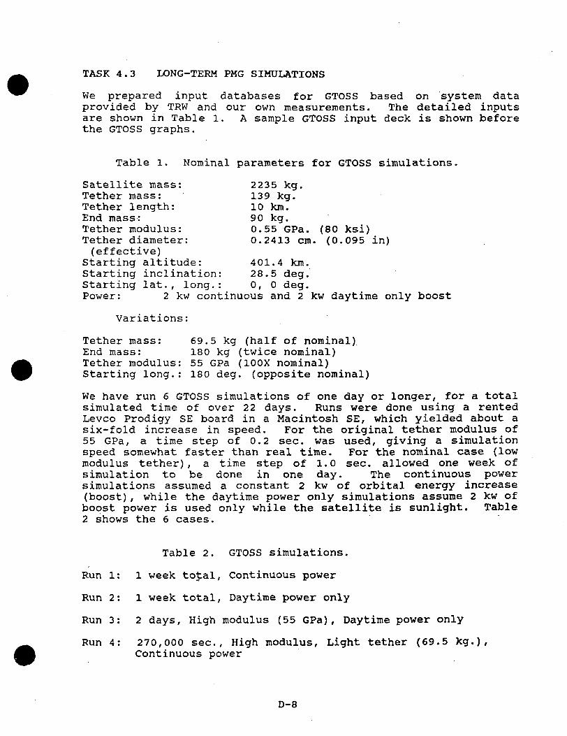
We prepared input databases for GTOSS based on system dataprovided by TRW and our own measurements. The detailed inputsare shown in Table l. A sample GTOSS input deck is shown beforethe GTOSS graphs.
Table l. Nominal parameters for GTOSS simulations.
Satellite mass: 2235 kg.Tether mass: 139 kg.Tether length: 10 km.End mass: 90 kg.Tether modulus: 0.55 GPa. (80 ksi)Tether diameter: 0.2413 cm. (0.095 in)(effective)
Starting altitude: 401.4 km.Starting inclination: 28.5 deg.Starting lat., long.: 0, 0 deg.Power: 2 kw continuous and 2 kw daytime only boost
Variations:
Tether mass: 69.5 kg (half of nominal)End mass: 180 kg (twice nominal)Tether modulus: 55 GPa (100X nominal)Starting long.: 180 deg. (opposite nominal)
We have run 6 GTOSS simulations of one day or longer, for a totalsimulated time of over 22 days. Runs were done using a rentedLevco Prodigy SE board in a Macintosh SE, which yielded about asix-fold increase in speed. For the original tether modulus of55 GPa, a time step of 0.2 sec. was used, giving a simulationspeed somewhat faster than real time. For the nominal case (lowmodulus tether), a time step of 1.0 sec. allowed one week ofsimulation to be done in one day. The continuous powersimulations assumed a constant 2 kw of orbital energy increase(boost), while the daytime power only simulations assume 2 kw ofboost power is used only while the satellite is sunlight. Table2 shows the 6 cases.
Table 2. GTOSS simulations.
Run l: 1 week total, Continuous power
Run 2: 1 week total, Daytime power only
Run 3: 2 days, High modulus (55 GPa), Daytime power only
Run 4: 270,000 sec., High modulus, Light tether (69.5 kg.),Continuous power
D-8

Run 5: 200,000 sec., High modulus, Light tether, 180 deg.longitude start, Daytime power only
Run 6: 100,000 sec., High modulus, light tether, heavy endmass(180 kg.), 180 deg. longitude start, Daytime power only
Graphic output was generated by the standard GTOSS programs setup for Macintosh use, along with the commercial softwareCricketGraph for generated plots. Because our Macintoshconfiguration does not allow for more than about 2 days of datato be saved, longer runs were generated by merging 2 data sets.For the 1 week runs, this leaves a gap of 200,000 seconds ongraphs of the entire interval.
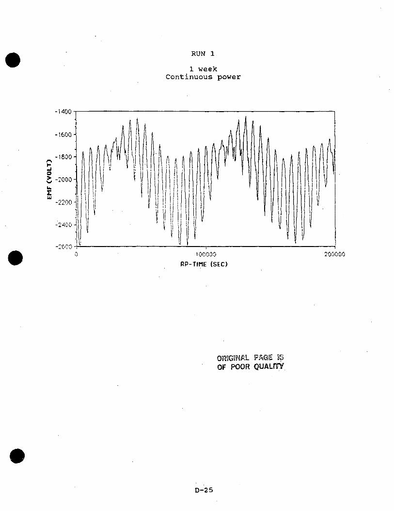
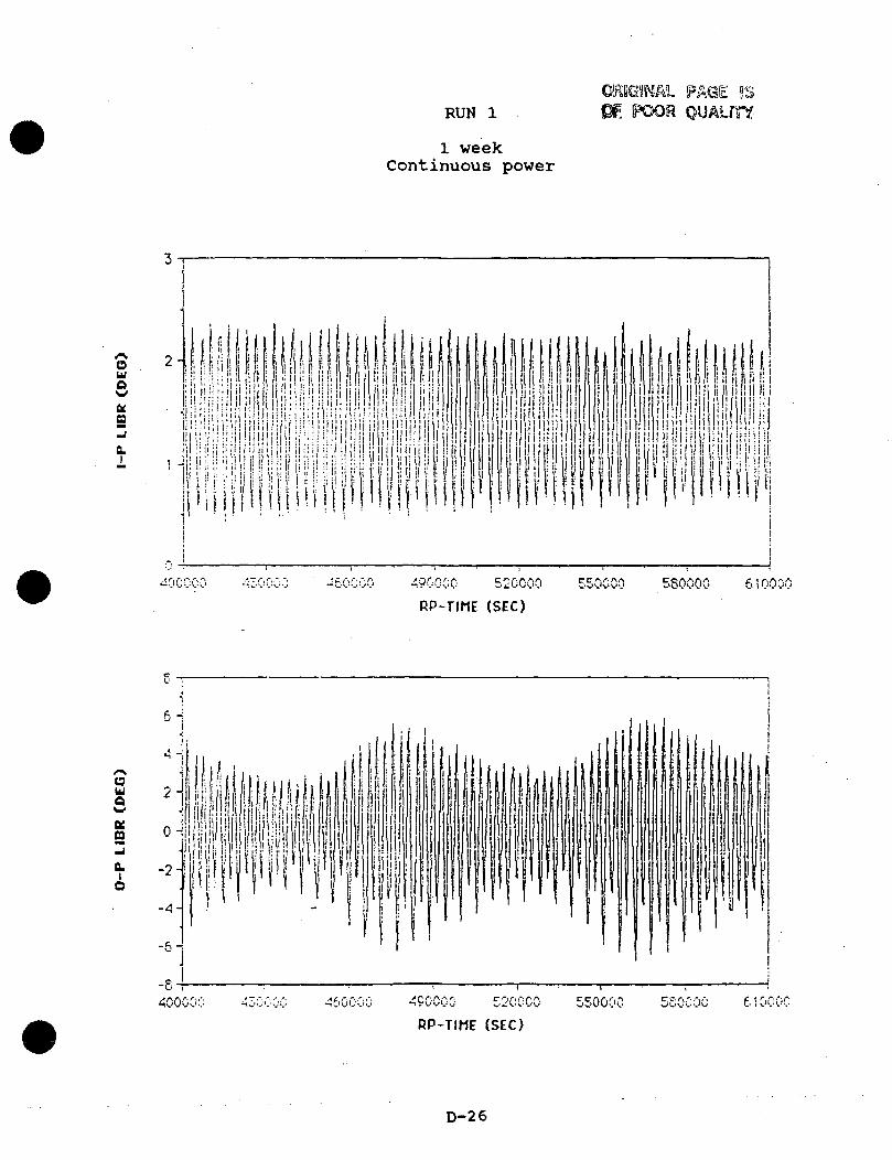
The standard data shown are the in and out-of-plane librations ofthe end mass relative to the satellite, and the altitude of thesatellite. In most cases, the tension at both ends of thetether, orbital inclination and eccentricity, and tether voltageare also shown.
The constant-power simulations show very docile behavior, and wehave difficulty imagining ways in which a constant-boost-poweroperation could get into difficulty, except by driving the systemso hard that the in-plane angle gets large (i.e., long-termboosting or deboosting at over 10 kw for the system parametersspecified) . However, note that the simulation over a one weekperiod does not show a steady state behavior. The out-of-planelibration amplitude is still building at the end of the week.
As expected, the daytime-power-only case has much largerlibration amplitudes. The out-of-plane libration amplitudebuilds up to about 20 degrees in less than one day (this is for apower level that gives an equilibrium in-plane angle of 1.75degrees in full-time operation). However, by the time thelibration amplitude grows to 20 degrees the frequency of freeout-of-plane libration drops nearly 3%, which limits the furthergrowth of the out-of-plane libration. Thereafter the system"breathes" diurnally, as the geomagnetic field rotates with theearth and varies the ,orbit inclination with respect to thegeomagnetic field between a minimum of 17 degrees and a maximumof 40 degrees.
In cases where operation starts when the geomagnetic inclinationis near maximum (i.e., when the satellite orbit ascending node isnear the international date line), the libration amplitude buildsup quicker than when operation starts with the ascending nodenear 0 longitude, but in either case, the limiting amplitude issimilar.
Simulations with factors of two change in the tether and theendmass show the qualitatively expected behavior. Out-of-planelibration builds up more slowly with both the heavy endmass andthe heavier tether.
D-9
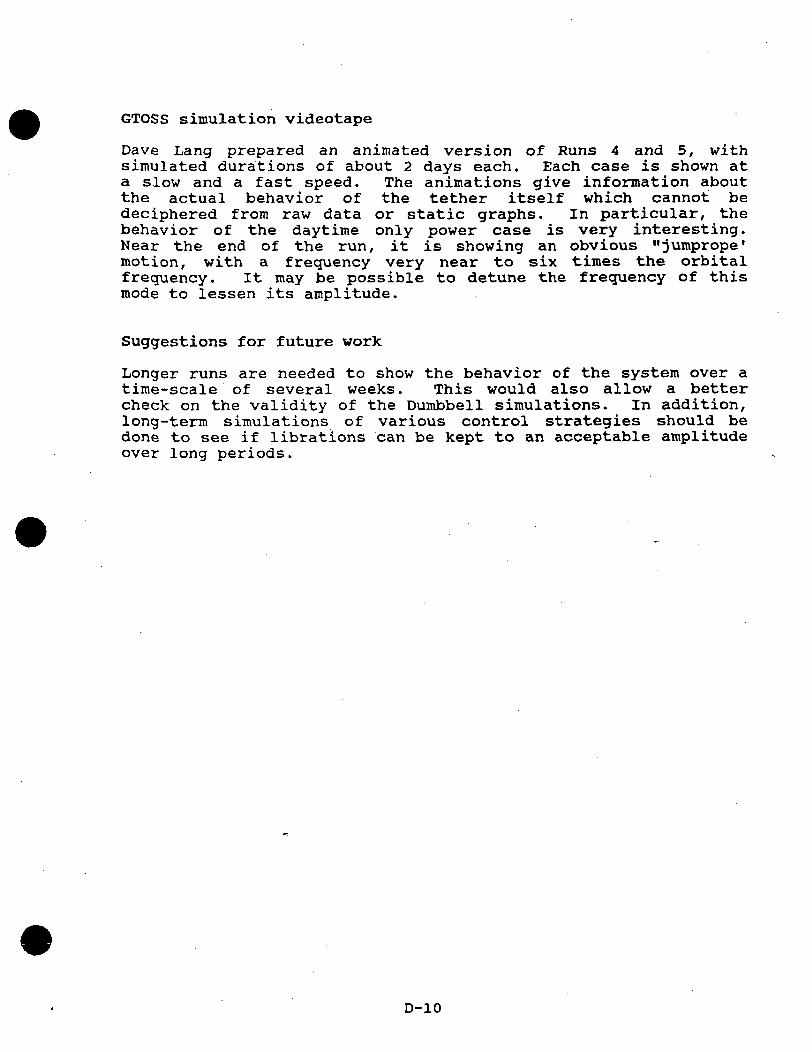
GTOSS simulation videotape
Dave Lang prepared an animated version of Runs 4 and 5, withsimulated durations of about 2 days each. Each case is shown ata slow and a fast speed. The animations give information aboutthe actual behavior of the tether itself which cannot bedeciphered from raw data or static graphs. In particular, thebehavior of the daytime only power case is very interesting.Near the end of the run, it is showing an obvious "jumprope1
motion, with a frequency very near to six times the orbitalfrequency. It may be possible to detune the frequency of thismode to lessen its amplitude.
Suggestions for future work
Longer runs are needed to show the behavior of the system over atime-scale of several weeks. This would also allow a bettercheck on the validity of the Dumbbell simulations. In addition,long-term simulations of various control strategies should bedone to see if librations can be kept to an acceptable amplitudeover long periods.
D-10

Guide to the DUMBBELL Videotape
To save time, the videotape was shot simply by pointing acamcorder at an IBM-PC monitor, running the program, and makingcomments as the program ran. The display is sketched below:
VU-*
The large circle on the right indicates the possible range ofmotion of a small upper end mass tethered to a larger object, asviewed from above in a LVLH reference frame moving with thedumbbell. The orbital velocity vector is to the right, as shownby the arrow. Thus what is seen is a projection of the endmass'sposition onto a horizontal plane. The marks on the screen showequal increments in in-plane and out-of-plane displacement, witheach mark indicating a displacement of 1/4 of the tether length.This corresponds to libration angles of 14, 30, 49, and 90degrees.
The endmass position is represented by the small moving square.Its position is calculated at 10 second intervals, and plotted at40 second intervals. At 80 second intervals, a "dot" is leftbehind the square as it moves away. This provides a graphicrecord of the envelope of attitude oscillation and of changes inthat envelope over time.
At the upper left the B-field and electromagnetic thrust vectorsare shown. The reference frame is the same LVLH rotating frameused in the large display, with the same overhead perspective.Hence the two lines on the screen represent the horizontalcomponents of the field and the thrust vector. The field lineorientation is mostly out-of-plane (vertical on the screen) forlow-inclination orbits. The thrust vector line runs mostly east(to the right for a low-inclination orbit). The thrust vectorline appears and disappears as current is turned on and off.Note that the component to the right is the in-plane force, whichcan be much larger than the net boosting force if Cos(Theta) issmall.
D-ll

<•. - . • . ' . ' . "
*. \
<•_
M „' . ' • ' •••-
.2 , • ' • ' • ' • ' • •rtiH C ' • ' • ' • 'kx • • • • • -.-....•H OJ
o , . - • ' • ' • •r r - < ' ' • • - .*-« *-4 . . • ••
•P D ' • • - . . .r~* r *~i . • • " ';•-* t* Jo . . ' • • • • • • •o o ' ' • • • • • -..
/•*-, . • • ' *'— * • • -
*.'.
cdt> • ' • ' • ' • ' • ' . . .•P L~ ' . ' . •• ' ' 'O f - . . . ' • ' • • • •
-p ..a • ' ' " • • • . •••a E-I. r- •- -••.- .• . ' .o c< • '!U M . ' . ' • - ••-i*•3 -P 0 •••• . • . ' . 'O -H 0
1 — • ' " • »
•H roi-j ..-.-. • '
j> ' " • • • . -..o o •••.-.•.>~* • . • • ' • ' • ''cu o
-v-3 '*^ '•'•'.
•H "£,0 or- ^> ' • ' • • • . . ,O r-i LT> ••• ' . ' . '
0 •C CO " • • • . - . .M C-J •'• '• '• . . ..
• • ' • ' • ' • ' . ' , . tob . '. '• " '•-!
o o • • • • ' . . ...''-• <~) ''" • • • •• °*-'-H \-J . . • ' • — *-
o n< • • • • - . . . -^o .-.•.-.• • ' '
J-3 * . . ' . : = • °rt o o ' • ; ; : : -.. ..n 2 o ' ' • : • • • • • &
a " • • : - . - . . wr1 •'•'•'. '>
p •••••.'••.: §M
. . - • • ' • ' - ^Q" • • : - . • S^;: :': •. -. - °
| ; :•'•' . .
''•'.'.
'.'_'
• " • ' . ' . .
'>* fi:i-'j :-.'.-;. -V! :•'.!•.:
1
1
• 1
lss• 4
•r-Jr— •
S;•-•;rt
».— *
1!1I(
|x.
:••;..;
Ji*.
i:.;.;
1 ••••
' *'••'
: ' fI?::••;•'.
".'•,;
J-. .'
;!(*
:\;
?*."•
;C/
*/.
•: .*
•: ;
*: '.
'•: ',
i.:? i''-0 K-•a ;;;-o ^::-r ;:'•« i:>
o jr.-j.':
• • \'-C3 i,'1:'-P I'-.o ••-.•-" :-H ^-
x ••••-.Jp> g-"" 6
?•:•.
K>:K;
v".
r'
<»•
•f<.<<<
(<<<</\
$si
17'^.. <j
^^ <;r-l )
•!T^ Sa <^ <3 <0 <
1;iiiiii
ORIGINAL PAGE ISOF POOR QUAUriY

ORIGINAL PAGE ISOf POOR QUALfTY
*. ',
'•'- '.
o*T- |P" ' ' : •••
c3 "" ' ' ' • • • • :._ 1 r -4 . . • * ' '
< 1 .-I '• • . .
!X • • • ° '"<~1 OJo>- i d , . • • • ' '-o D Xrt coo • • • • • • . • ; .00 ,.• • • •''
/— N • • • . ...
rt«> ' V. ' . ' • ' • ' • -o i r\ '" • • .•*—* i— i -..a t - • • • • : : ' • '
-j-> ,-•:: • , • • • • ' • 'G H r-O 0'S-, r.-.ir ' •. *i-l . • ' •
•3 -'-> 0 " • • • • . ,.O -H O ••••'.'. . ._
•H r«j '"; ; : •. •. •••i — C ' • • . ,
&o o ' • ' • • • • • . .' - ^ • • * • • " '
*.'.-! " • • • .
D-, o•i O ' ' • • .*•*— * ,- -t . •
•H J.H,0 o , - . - • • • •f - H ^ . . ' • • • •
o iH ir> ' " • • • . =-o • ••••'.'. . . _Cl '-- ' ,• • • ' 'n oj \\ ; : •. •• •••
•• .• . • . ' / 'f c . . - • • ' "
q o.a o ,-.• '• ; : '"
o c- i : : : • • •a "
-•-> » - • • • . • . ' ' torJ O O ... • • • '•' o
•i-> cd • ' ' : : -. •- 73co ,o o
<y -.-.•.-. ""or-1 ; :- ^*.• • < . . • «« J
E - ' • • • • : : . !•'•'•'• • . ,. o
' . ' . ' • • •• ' • ' . . r!*>' • :. t -i
CO.... • •' •" >
• • - . - . - ac
' • ' • ' • ' . y••'•'• • • .. T!-••'•' •' .' . .. o
• • * * • ' * * '.* ~ '• ' .••'"•• - .*'
> **** . ' •'•-.!' •"' ••* ' .._**•" .1"
/;*••• .">*'** '* • •'"' * •' . ** * *:-./•'; •./
.*.**
"'•:-* >'-,.
* ^'
i't" ' '; >
"*»..
'";.,
-..•• '' '\\
*>'* ~\
%.v' \f •
\'f.
./'';,
X..
/'"'\.*»
/'\..•'•>,;
'">,s'
it,f'i''f
\f
"'y';>."*/
'"2.1.''••,. :•
t.3 <''•"o -^•o S
C9 <- *>I C
0 £*».
^•r-I C'
£ >K <../jj '"X;..: ..--•
*iC.
*
• . •
\
,'. • . • *
-V •.'•;,'/.'
s\ '
;•;:'_»• *
*•' •'*.
"<; .' *. '
':?• '
'•';'
•*.'•;.. .'
' * '£ "
';%
• • "•.**. ;\.* i'-
\'-:;'!•'
^ •.-:;
'/%•• _/'•. .
w ' ;.V--G • •:.••. •'0 £
• V
9 £— w • .*.
I ISo -;s
;.;^
• • *•• *.
o3 ;•:jjo ij-C :••c-» -,:
t-4 ;••j '*jd \j
.-• i y\
^
: _*:
v
-
• .. *.
' " ' •* f.
.
* /.^
s " .
t'f.
• ...
' ' • ; ...
. • /
' _ •- ....
' ''^
..;••>•.•_•' •'"
' '; •.-.«/.. • •
OJ ' ' "• 1 •' •••*" ' "Vs:'i.• • '
-J ' /••'i '. r< . • •'3 "• • ' • ' • ..
»~H .•'
£ ":>G "-"vG) -.:•:.C,JU -;':,
3~"">J> . . • • "d • • - . . .*— • ^.-. ,.-•
t ;'r>
D-13
Ho , - • • • • ' "
*>• '"-"• ' ' ' • • *r t ' • ' • • - . .
.— ) _C « • . - • • "P-., . . ' • ' • • • •
• - i cv ' • • • • - . - ,O ' • • • ' • ' . ' .s- c: , • • • • ' • '
•!-> 3ci oo ' • ' • • • • .c • .-.•. • • ' 'o o . . ' . ' • '• v
P; x ;.;•.•. - . - . -
cd o . '. '• •••-P i.r-i • ' • ' • • - . .o i-- -.•.•.•/ " .
i ^ r™* . '• •-i-5 A-i • ,. • • •c: EH v- • • • • • . , .CD O' ' • ' • ' • ' •t, CvJ£-< ' '• '• '•'b -'-> o0 -H 0 • • - • . - . ' . '
13 • . . • • • • ' "•H C^J " ' ' •. -.-,-1 • • • ' • ' • ' . . ...
^ , - • • • • ' 'o o • • • • , .,a • -••.•/.' 'o- * o , • • • • ' • •
-;-J »o " • • • •..•H J, '••• ' . ' . ' . ' .-G Or _ ' • • • . .• - < ^ > . . - • • •o r-i in ' ' " • • • • .o • ••.•/ • ' '
a co . . . • ' • • •-H c>j ;;: •. -. -..
- ' • ' • ' • ' - ' . ' . t jo&o • ' • ' • ' • ' • ' . ' °•H . , -.•.• . ' .• •'- '°- H O , • • • • ' • ' 0o a, • • -. -. •.. 2
o ••••'.'. . .. ~|•p o - . - . • . • . - • ort o o . . . ' • • •- u1 \ *«^ '• ••^ r t • : • • • . .co ,0 o -••.- . ' . . C3yi\ • . . ••• l~l2 • • • • • - • . . . . 0i t ; .... • • • • • >c ' ' • . - . • - - o
'•'•'• . .- rj••.-.• • ' :' H. . ' : '• :' .O
'* * • t
• ' • ' • ' • ' - . . ' . ^5'-'. .••.•/.'. '
> ~ . . • • ' • ' •s c • ' • • . .^ i -.•.•.•.•;
'ii,
'i
'
-
<iii O ia
-a <
o1o
*» i(~^
9i,'N!
C'j•r**2T
"O,*\'O
O— -v
1O
• •
cci^jc^.rjH
1 *»1' *«
rd•:•-«
f\jJ <
t—
• •
-J-5 1r-! ,
_3r —1
-° 1CG 'Cj (»^^ '
^NH ,f-*1 '^J
O <t. '"1 1_J^co ,
t — 4
(
1
I
I
1
I
1
1
ORIGINAL PAGE S3OF. POOR QUALITY
D-14

DUMBBELL is written in Borland Turbo-Pascal 4.0. It runs onIBM/PC-compatible micros and generates a graphics display as itruns. With an 8087 co-processor, double-precision numbers, and10-second timesteps, the program takes about 8 seconds per orbit.
DUMBBELL Inputs
The program begins with a default set of inputs, and the usersupplies replacement values interactively. The parameters are:
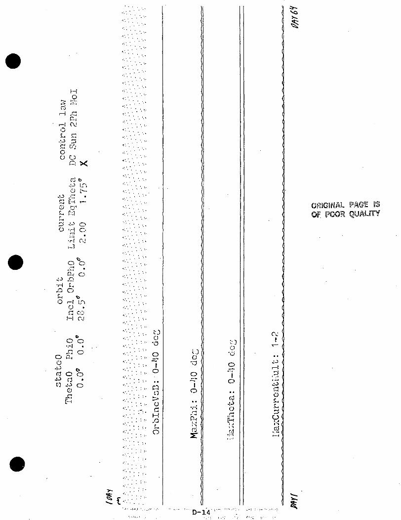
-ThetaO: Initial in-plane libration angle in degrees.PhiO: Initial out-of-plane angle in degreesIncl: Orbit inclination in degreesOrbPhO: Initial orbit phase (from ascending node), in degreesLimit: Maximum current allowed, compared to vertical tetherEqTheta: Equilibrium theta due to electrodynamic torque
Theta and Phi are "clock" and "cone" angles in a local-vertical,local-horizontal reference frame, with positive theta indicatingdisplacement of the upper (smaller) end mass in the direction ofthe orbital velocity vector, and positive Phi representing adisplacement to the left of the velocity vector. The initialTheta and Phi rates are both assumed to be zero. The currentlimit parameter comes into play when the libration angle islarge. With Limit=2.0, when libration causes the EMF to go downto less than half the value for a vertical tether, then thecurrent is limited to twice the vertical-tether current. Also,if the libration angle is large enough to make the EMF changesign, the current is turned off entirely.
The control law options are:
DC: Fixed power (and hence fixed force along velocity vector)Sun: Fixed power in sun, no power in shade2Ph: Fixed power within 45 deg of nodes; no power otherwiseNol: No current; over-rides the EqTheta input.
Explanation of DUMBBELL Viewgraphs
Each viewgraph lists the inputs at the top, and four key outputparameters plotted at a rate of one data point per orbit. Thetop value (OrblncVsB) is the "geomagnetic inclination" of theorbit, halfway through that orbit. It varies from 17 to 40degrees each day for all the runs shown. Below that are MaxPhiand MaxTheta, the maximum absolute Phi and Theta displacementsduring that orbit, with 0 degrees at the bottom of each plot and40 degrees at the bottom of the next plot upwards. Finally,"MaxCurrentMult" (with a range of 1.0 to 2.0) is the relativecurrent required to give a fixed boosting force. Note that whenthis value is above "Limit" (the input parameter), the net poweris scaled back to stay within the limit, but the plot shows thecurrent that would have been used without the Limit constraint.
D-15

Simulations of Dumbbell Behavior
The slow execution speed of GTOSS severely limited the number oflong-term GTOSS runs possible under this contract. To supplementthe GTOSS work, we wrote a simple rigid-dumbbell electrodynamictether simulation program, DUMBBELL. It runs fast enough toallow us to simulate months of dynamic behavior in a few hours.The key program assumptions and results are described below.
"DUMBBELL" Program Description
DUMBBELL models the attitude motion of a rigid dumbbell incircular earth orbit, in response to gravity gradient andelectrodynamic torques. It models gravity gradient attitudedynamics using the general equation of attitude motion listed inthe Appendix to the paper "The Behavior of Long Tethers in Space"(David A. Arnold, in Journal of the Astronautical Sciences, Jan-Mar 1987) . The length-change terms are set to zero. Note thatthis equation linearizes gravity and assumes a spherical earth.
DUMBBELL does not model perturbations due to air-drag or earthoblateness on the attitude motion of the object. However it doestake into account the effect of nodal recession on the phasing ofthe day/night cycle with respect to the orbit's ascending node.This typically goes through a complete cycle in roughly 50 days.The earth's magnetic field is modeled as a simple dipole tilted11.5 degrees with respect to the earth's axis of rotation. Thefield rotates with the earth. This causes the "geomagneticinclination" of the orbit to vary over a 23 degree range eachday: from 17 to 40 degrees and back for a 28.5 degree orbitinclination. This variation in geomagnetic inclination causesthe out-of-plane component of electrodynamic force on a verticaltether to vary from Tan(17) to Tan(40) times the in-planecomponent. Since the in-plane "boosting" force and torque areconstant (for a constant-net-power control strategy), the out-of-plane forces vary by almost a factor of 3 during the day. Themotion of the field with respect to the orbit also causes theorbit's ascending node with respect to the field to oscillate,over a total range of about 80 degrees for a 28.5 degree orbit.
DUMBBELL does not include the offset of the earth's magneticfield from the center of the earth, or the higher harmonics ofthe field. When an electrodynamic tether is operated on aconstant-net-power basis, variations in field strength cause EMFand thus current variations that compensate for the field-strength variations". We did not model higher-order terms of thefield because of time limitations, and because higher harmonicsare smaller and mostly average out over time due to the earth'srotation under the orbit.
D-16

Near the end of the B-field and thrust vectors two small brightspots can be seen moving around on the display. The left-to-right distance between the end of each vector and the nearby spotrepresents the vertical component of that vector, on the samescale as the horizontal component. If the spot is to the rightof the tip of the vector, then the vertical component is upward;if to the left, then the vertical component is downard. We havefound it instructive to freeze the display and position twopencils in front of the screen to show the tether and fieldorientations. This allows visualization of the tether, field,and thrust vectors in 3-D.
At the lower left is a summary set of plots similar to theDUMBBELL viewgraphs, except that the order is different:OrblncVsB is shown on top, followed by MaxTheta and then byMaxPhi. This plot uses 1 column per orbit and takes 720 orbitsto "march" across the screen. If the run lasts over 720 orbits,then the plot starts over at the left side and superimposes newdata on the old data.
To provide a proper context for understanding the effects ofelectrodynamic forces on the tether, the video starts off withseveral cases of free libration: in-plane, out-of-plane, andcombined, with amplitudes of 15 and 30 degrees. Then tetherelectrodynamic forces are added, first as a small perturbation ona large free libration, and then for the two cases of greatestpractical interest: "DC" and "Sun-only" boosting at the 2-KWlevel, using the baseline TRW PMG hardware design. Because ofthe duration of the last two simulations (several hours runtime), only selected portions of each run are shown. In tabularform, the cases shown on the video are:
CASES SHOWN ON "DUMBBELL" VIDEOTAPE:
Short runs:
ThetaO
153000153030
Long PMG runs: 00
PhiO
001530153030
00
Power
0000002KW
2KW "DC"2KW when in sun
D-17

ORIGINAL PAGE !SOF POOR QUALITY
$TFW301 OENERIC FiDB HfiME FOR SERIESTRUM43: 3 BEflD SQLN FOR TRW PUG OMU, grav grad. startdownward DEPLOY flT 400 km, 23.5 DEC ORB, 2~kw cont.
1 1.0 DELTHT: REF FT2 610000. TMflX3 500.0 N, THE RDB SOLM OUTPUT INTERVAL = M * DELTflT4 400000. STfiRT RDB OUTPUT RT THIS TINE16 43.00 RUN NUMBER
C QUICK LOOK PAGE FORtlAT CONTROL117 1. SELECT QUICK LOOK PflGE FORMflT381 2.0 CHOOSE TOSS OBJ FOR QUICK LOOK (IF RPPROP)3S2 2. . . . .t;Op, ?
421 1.0 CHOOSE TOSS TETHER FOR QUICK LOOK (IF RPPROP)422 2. ,..433 2. "435 1.0 CHOOSE FINITE SOLN FOR QUICK LOOK (IF ftPPROP)442 1. SEfiO NUflBER TO DISPLftV FOR QUICK LOOK <IF ftPPROP)44:'-;
C GTGSS EXECUTION. CONTROL DftTfi111 1.0 IHUOKE RP PRRTICLE DVNflMICS112 0..0 IHUOKE RP EULER fiHOLE DEFINITION113 2. NUMBER OF LfiST TOSS OBJECT BEING SIMULFiTED114 1. NUMBER OF fiTTRCH PTS ON THE REF POINT
C BflSIC REF PT GEOMETRY455 0. INUOKE-flERO DRRG ON REF PT455 0.0 REF PT fiERQ REF flREfl (SQ-FTJ457 0.0 • REF PT DRRG COEFF
20 153.196 REFERENCE PT HfiSS (SLUGS)21 50000. IXX: REF FT (SLUG-FT+*2)22 50000. IVV23 50000. IZZ
C REF FT TRRNSLRTI ON STfiTE iNITIRLIZRTiON100 0.0 TRNS 1C OPT: =0. FOR TOPO; =1. FOR INERT IRL81 0.0 XIO REF PT POSITION (FT) UNER FRfiMEJS2 0. VIQ "83 0. 210 "84 0.0 X IDO REF PT RflTE <FT/SEC) IIMER FFiliME]85 0. V iDO "86 0. 21 DO "101 1316900.0 REF FT fiLT C.FT>102 0.0 F;EF PT TOPO LONGITUDE (DEG)103 0.0 REF PT TOPO LATITUDE <DEO)107 12005.12 UXTO (FT/SEC) RP INER UEL COUP [RP TOPO FRflMElIDS 22110.67 WTO'09 0. vZTO
C REF PT ROTfiTIOM STfiTE INITIftLIZfiTION90 2.0 EULER 1C OPT: =0. FOR ORB; =1. FOR TOPO; =2. INER104 0.0 PITCHO (DEG) EULER RNG ICS105 0. nOLLO
D-18

ORIGINAL PAGE ISOF POOR QUALITY
106 0. VFll-JO87 0.0 OMXBO: REF PT BODV RNG UEL (ORB RRTE = .06983 0. OMBVO " (ORB RftTE=-0.0692)89 0. OMZBO0 END OF REF POINT RND TEST BED DfiTfl
======> GENERRL <======= RERD-IN LTOSQ fiRRRV HERE - INTEGER CONSTRNTS125 0 TOSS-HIDE EULER RNGLE DEFINITION23 1 INUOKE TOSS-WIDE PftRTICLE DVNftMICS24 1 TOTflL NUMBER OF TETHERS120 1 NUMBER OF FINITE TETHERS234 5 RSSIGN PWR GEN SCEMftRIQ 2 TO TOSS TETHER »1198 1 TVPE OF FINITE SOLN *1 CO=MODfiL, 1=STO BEfiO MODEL,4=frozen)284 1 gray grad start for tether a1207 3 NUMBER OF BEfiDS FOR FINITE SOLN* 1194 0 EUfiL OPTION -GRflU GEN FORCES, FOR "HLL" FINIT TETH SOLNS195 -1 EvftL OPTION -fiERO GEN FORCES, FOR "RLL" FINIT TETH SOLNS196 0 EUfiL OPTION -ELEC GEN FORCES, FOR "RLL" FINIT TETH SOLNS130 . 1 ftSSIGN FINITE TETHER SOLN 1 TO TOSS TETHER *125 1 OBJ * TO WHICH "X" EHD RTTRCHES-TETHER *150 1 HIT PT *. FOR "X" EHD OF TETHER *175 2 OBJ - TO'WHICH "V" END RTTRCHES-TETHER «1100 1 fiTT FT *, FOR "V" END OF TETHER *10 0 EHD OF DfiTS
_ REfiD-IN JTOSO ftRFifiV HERE - INTEGER URRIfiBLES0 0 EKD OF DfiTfi
PERD-IN FTOSQ flRRRV HERE - REfiL CONSTANTS145 0.0 FINIT TETH INTEG INTUL: SOLN *1 < ««««25 12.620 SPRING RfiTE - MfiSSLESS TETHER *150 32S08.5 UN-STRETCHED LENGTH - TETHER *173 0.0 DRMFIN5 CONST - HR55LE55 TETHER "1100 9.3268 LINERL DENS CLhB/IOGOFT) FOR FINITE TETH SOLN 1109 80000. VOUNGS MODULUS (PSD FOR FINITE TETH SOLN 1118 .09500 ELftSTIC Dlfl <IN) FOR FINITE TETH SOLN 1127 0.01 BETfi DfiMPNG FfiC (/SEC) FOR FINITE TETH SOLN 1154 .11420 fiERODVMfiMIC Difl (IN) FOR FINITE TETH SOLN 1181 9.0 INITIfiL CURRENT (flMPS) FOR FINITE TETH SOLN 1
C DEFINE ELECTRO POWER GENERATION SCENRRIO NUMBER 5389 2.0 TVPE:day/night 2km constant394 0.0 fiBSOLUTE TIME(SEC) TO START POWER GEN SCENARIO 5
404 -2.0 day PWR LEUEL CfO!) - PERIOD 1, SCENRRIO 5414 100. MflX LIMIT CURRENT <ftMPS> - PERIOD 1, SCENfiRIO 5
424 -2.0 niqht PWR LEUEL <KW> - PERIOD 2.' SCENfiRIO 2434 100. MRX LIMIT CURRENT CfiMPS) - PERIOD 2, SCENRRIO 5
504 0.0 BEGINNING PWR LEUEL-<KU> - PERIOD 6, SCEHflRIO 5509 0.0 ENDING PWR LEUEL <KM) - PERIOD 6, SCENfiRIO 5
335 1.0 PUR MULTIPLIER (DEFRULTS TO 1.) - TOSS TETHER *1END DnTfi
REfiD-iN DTOSQ fiRRRV HERE - REflL URRIflBLES0.0 END DfiTfi
D-19

ORIGINAL PAGE ISOF POOR QUALfTY
======> OBJECT 2 <====== REftD-IH LTOS2 ftRRflV HERE - INTEGER COMSTfiHTS13 1 * OF fiTTflCH POINTS OH THIS OBJECT19 • 0 .GT. 0 INVOKES ftERO CftLC ON OBJECT21 2-L ICTRH SELECTS TRRNS STflTE 1C OPT I OH, =0 FOR TOSS I HER COORDS22 5 LICROT SELECTS ROTfiT STfiTE 1C OPTION, =0 FOR DIRECT COS ENTRV
0 0 END OF DRTflREflD-IN JTOS2 flRRRV HERE - INTEGER URRIRELES
0 0 END OF OfiTfl^ REfiD-IN FTOS2 ftRRflV HERE - RERL CONSTRNTS
3 6.167 I HITlfiL MRSS FOR THIS OBJECT4 10000.0 INIT1RL IXX FOR THIS OBJECT5 10000.0 " IVV6 10000.0 " IZZ
102 0.0 R'ERO-REF RRER <SQ-FT>103 0.0 QftP.G COEF
40 0.0 IHITIRL POSITION X COORD (OF OBJECT UR/T F;P>41 o. " " "42 ' 32808.5 " " Z43 0.0 IN IT IRL FifiTE X COORD (OF.OBJECT WR/T RP)44 0. - ' " . . . . .45 0. " 2
46 0.0 INITIfiL OMXB fiMG RftTE (IHER) OF OBJECT47 0. " OMVB " . "48 0. " OUZB "49 0.0 miTIFiL EULER PITCH OF OBJECT50 0. " ROLL51 0. " VFiU
0 0.0 END DRTHRERD-IN DTOS2 RRRftV HERE - REflL UflRIRBLES
0 0.0 END DflTfl; > ;• > > ;• >; > > ;• ;• > > ;• ;• ;• > > END OF TRUH40 « «<: < < < «<:««««:«< <> :4:*:4^+#*+++++****+++**4^
-1
D-20

RUN 1
1 weekContinuous power
ORIGSNAL PAGE ISOF POQR QUALfTY
ou
400000
RP-TIME (SEC)
600000
O
tt
fl.lO
-5-r400000
RP-TIhE (SEC)
600000
D-21

RUN 1
1 weekContinuous power
ou
£23
o-!1
ioooooRP-TIME (SEC)
'OOOOO
o
IS
a.o
\!\O-i i i !l Illll
-4 -f-
0
'
' I I i in
HI i i r i r
f
ilirMuiifjjfjjhff" " M
iOOOOO
RP-TIME (SEC)
20COOO
D-22.

ORIGINAL PAGE 53OF POOR QUALITY
RUN 1
1 weekContinuous power
450
440 -
* 430 -ufi
420 -
4:01
100000
RP-TIME (SEC)
COzw
=; -i
4 -
1000CO
RP-TIME (SEC)
200000
D-23

RUN 1
1 weekContinuous power
ORIGINAL PAGE IS
POOR QUALITY
i
ii
i'O .S~> "7"
100000
RP-TIME (SEC)
20C
0 0002 4•> 00000
RP-TIME (SEC)
200000
D-24
RUN 1
1 weekContinuous power
-1400
H1-2600 -r1
0 100COO
RP-TIME (SEC)
200000
ORIGINAL P&QE &5OF POOR QUALfFY
D-25
RUN 1
1 weekContinuous power
POOR QUALITY
oue>
a.
|H: fc k (1
I IS ii'! ! ': 1 Ii il !i I1!! i
1 1i i ;
1ii ii .1!i H Jli
f!|HI | ll Uiilii lllii H
If'!!
400000 49CCCO 520COO
RP-TIME (SEC)
580000 r i r*Ar- AO I >.'U-.".'
5-y
GUA
a.o
6 "I
2
°~j
-2-
-4-
-6
IS•^ I I I ' f . 11
iilil
-8-i400000
jl 11 ,!
43CCOO -460000 50000 52COC
RP-TIME (SEC)
50000
D-26

RUN 1
1 weekContinuous power
OfiSeSNAL PAGE ISOF POOR QUALTTY
:oO
* c. 10 Jw - ' J Iuo
-
•400000 -^30000 450000 ^50000 520000
RP-TIME (SEC)
550000 580000 610000
V)
u
Ul
X
5 -
/vVvx^V\^^' I ' ! • 1
400000 430000 460000 450000 520000 550000 5SOOOO 610000
RP-TIME (SEC)
D-27

ORIGINAL PAGE »SOF POOR QUALfTY
RUN 1
1 weekContinuous power
26.-41
•iO.-:O T - • - ! • • 1- ' , 1 ' 1 • i400000 430000 460000 490000 520000 - 550000 580000 6 IOC
RP-TIME (SEC)
0.0004-j
j.H02P 0.0003-zUluuu
0.0002-
j
1t
VM> iiii\\\iii 11 II
HI m
n / « /f! 1 f 11j
i ii < i ] i
hil j J
'Mii
»
fL-(
I/ I1 11 1j I1 t/1j
i
ui
iii
iiiii/IiijI
1 i!
IM
i jr
iIji1iIi
l i ' li 1400000 430000 460000 490000 520000 550000 5&0000 6KK
RP-TIME (SEC)
D-28

RUN 1
1 weekContinuous power
-1200
400000 4300CO 4&0000 ' 490000 520000
RP-TIME (SEC)
550000 580000 610000
D-29

Run 2
1 weekDaytime only power
ouc
a.o
200000 400000
RP-TIME (SEC)
600000
uO
s3
200000 400000
RP-TIME (SEC)
600000
D-30
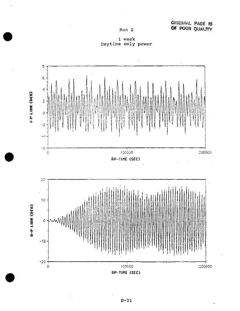
Run 2
1 weekDaytime only power
OF POOR QUAlfTY
ou
Q30.
i00000
RP-TIME (SEC)
200000
uw
ffi3o.o
-20100000
RP-TIME (SEC)
0COOO
D-31

Run 2
1 weekDaytime only power
440
430-1
w |§ 420 i
. A i'• >\ n i
,, !\ Ailn ' ; » i r 1 I
10COOO
RP-TIME (SEC)
200000
w
Aux
iCOOCO
RP-TIME (SFC)
200000
D-32

Run 2
1 weekDaytime only power
13OF POOR QUALffY
25.51
ttuc
moeo
28.50
28.49 n
25.HS-!
2&.H/ -r
A H I i ll\ !\ A A A I
./ ' i /W\ i\ i\ A
100000
RP-TIME (SEC)
200000
0.002 -r
>-
o
H 0.001 -uUUu
0.000 4-0 100000
RP-TIME (SEC)
200000
D-33

ORIGINAL PAGE ISOF POOR QUALITY
Run 2
1 weekDaytime only power
CDu
tta
ai
.I •
, IIt / .
11 1
2 -
0 -
.-;l i i i i i ' i i !JF I IB I I INHI !
'i i * {'
iUl.iiinil n i
•400000
' [ I
f
uI \
' HP «lHi nliP-iil1 I'll'III ill! Ill'
I M
500000
RP-TIME (SEC)
/•vawaw
OfCD
a.o
20
10-1
cH:
-10-
ill'
l i t ! i !•|ii! l i t e ill
Ml'
II,!i!!
1 1 1
i i i
_._ i-_:u400000
r*. r\ r\ r. r-*"w'VV'.JV
RP-TIME (SEC)
eooooo
D-34

Run 2
1 weekDaytime only power
520
IKwUA
H_!
500000
RP-TIME (SEC)
600000
/•«,
>w
uX
400000 500000
RP-TIME (SEC)
600000
D-35

Run 2
1 weekDaytime only power
ORIGINAL PAGE ISOF POOR QUALITY
ou
aKO
28.45-
26.44-i
".'P. ^ A
U\1 « A
N l\ n ft^ " V uy
• *
500000
RP-TIME (SEC)
/1 ; /* n rs.1 V V i- ' i j l i' ' r '/ W L
600000
r>. ".*." •500000
RP-TIME (SEC)
D-36
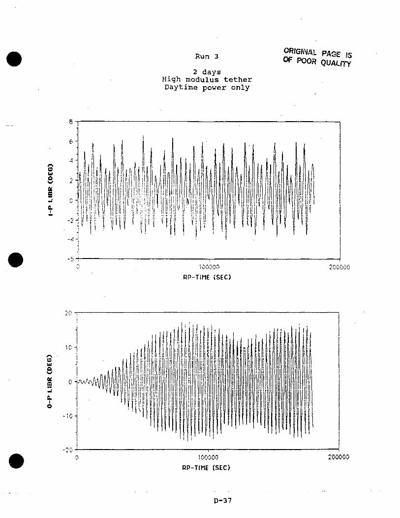
Run 3
2 daysHigh modulus tetherDaytime power only
ORIGINAL PAGE IS
& POOR QUALITY
(9u£wtt09
Q.
6 J
IM.i p 1 1
f S |i ii i!l
| 1 1 1 ! P I• ' I I I i l l i Win HI- i!i!l III !i!li!i !p! M III) lit i!•i !' i i! ii I i ii!:!! '! !' ' ii
100000
RP-TIME (SEC)
200000
wA
Q.
O
0-iJ
100000
RP-TIME (SEC)
200000
D-37
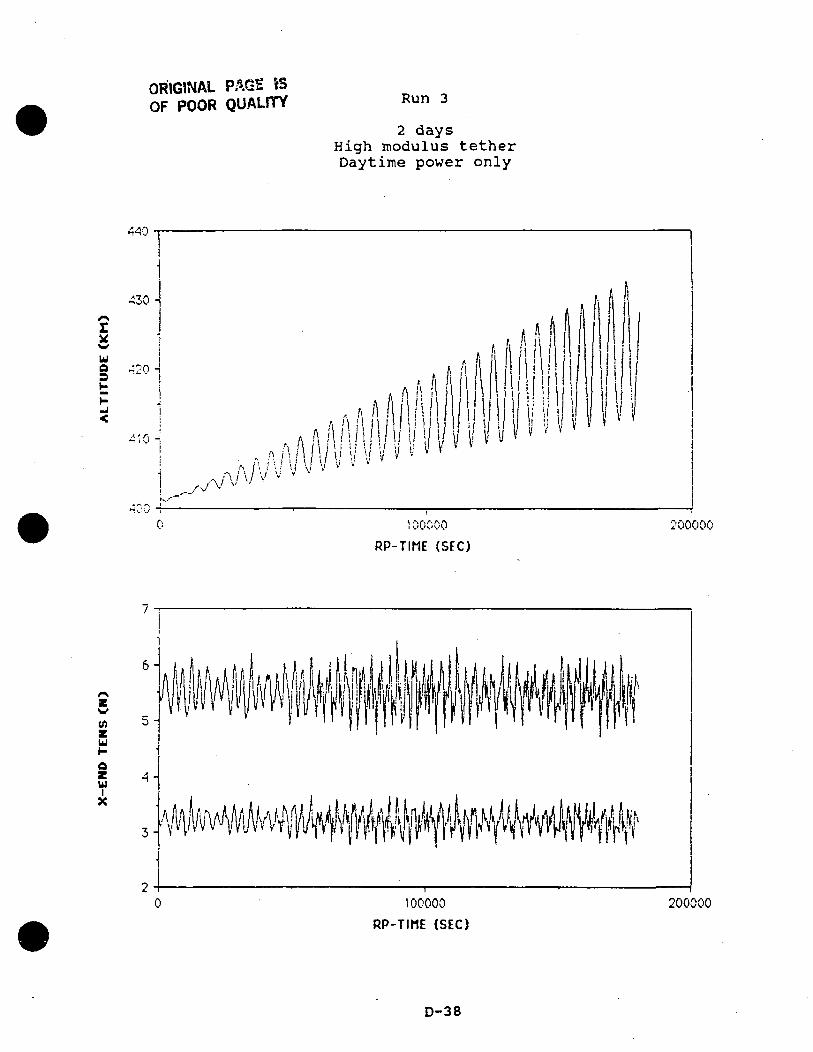
ORIGINAL PAGE ISOF POOR QUALITY Run 3
2 daysHigh modulus tetherDaytime power only
*»H'J -
.
^30 -f\IkW
uQ r->oD --o -£H.J<
~'0 -. ! V —
*
x^-1"**v.--i_< -
f
~- — — ^^
.
. ! \\» / A ;
- ft A / i I ftaAlHllll i 1
-, rAA / //111 IM/J•^ A f5 / '• • / \; / I l v V v •' v '^^•\A/ \y v v v/ v ^' .••f'~~'' ~*' • ^___ —T—
100000
^
. f,(, A l
'
'
I' l'S ' "
^— 1^ ^ "•»^
— —
f /i,M
U11!i »'V i'
.
> ii/
* •11 1 '1 ! 1i | I
wif 1Hil
— -1— .
/ * i
1
111 JI) 11 If f
"
200
RP-TIME (SEC)
U
azUIX
100000
RP-TIME (SEC)
200000
D-38

Run 3
2 daysHigh modulus tetherDaytime power only
i00000
RP-TIME (SEC)
200000
0.0004100000
RP-TIME (SEC)
200000
ORIGINAL PAGE f5OF POOR QUALITY
D-39

oa
£_j
*
ouo
0.Io
0-v
-6-?
Run 4
ORIGINAL PAGE
OF POOR
270,000 sec.High modulus, light tether
Continuous power
100000 20COOO
RP-TIME (SEC)
i00000
300000
300000
RP-TIME (SEC)
D-40

Run 4
270,000 sec.High modulus, light tether
Continuous power
450
440
ufisH
IOOOCO 200000
RP-TIME (SEC)
300000
v>u
uX
100000 200000RP-TIME (SEC)
300000
D-41

Run 5
200,000 sec.High modulus, light tether180 deg. longitude start
Daytime power only
(9u
-2J
\00000
RP-TIME (SEC)
200000
30
ua
ffi
0.Io
-20-
-30-100000
RP-TIME (SEC)
200000
D-42

Run 5
200,000 sec.High modulus, light tether180 deg. longitude start
Daytime power only
43CM
ua
.a ft iw u i l I
I I
100000
RP-TIME (SEC)
2000CO
CD
U
ouX
1COOOO
RP-TIME (SEC)
200000
D-43

0u
OfQ
fl.
ORIGINAL PAGE mOF POOR QUALflTY
Run 6
100,000 sec.High modulus, light tether, heavy endmass
180 deg. longitude startDaytime power only
Mi) /
20000 6^<iA/\v v *.- V 100000
RP-TIME (SEC)
oufi
COZja.o
-2020000 40000 60000
RP-TIME (SEC)
50000 100000
D-44

Run 6
100,000 sec.High modulus, light tether, heavy endmass
180 deg. longitude startDaytime power only
420
390JOOO 40000 60000
RP-TIME (SEC)
eoooo 100000
D-45

a.a.

Interoffice CorrespondenceTRW Space and Technology GroupEngineering and Test Division
Subject
Comments on ESL Report to TRWon Electrodynamic Tether Stability
ToJ D. Younkin ;'// > ? > '
Date
15 June 198888X131.2-044
ecJ. BernierM.A. Chory
Location/Phone
82/2045536-2092
After reviewing the Energy Sciences Laboratories (ESL) report (Attachment 1) and thetwo accompanying video tapes, I made the following observations:
1. The first video tape shows extensive long-term simulation runs using a dumbbelltether model, however these runs were not requested in the SOW (Attachment 2),and there is no mention of these runs in the report (except the one-page guide tothe monitor display). There is no explanation (during the narration of the runs)for the choice of initial conditions that deviate from the nominal vertical. Theruns cover a simulated period of several weeks (?), and considerable discussion isprovided about the results from these runs, which are of dubious value, consideringthe issues raised in item (2).
2. The second video shows the results from the GTOSS runs extending over a simu-lated time of about two days. The dynamic behavior shown during the run in whichthe tether is operating only in daylight exhibits the "jumprope" motion, and thetip motion develops in-phase (same frequency) in-plane and out-of-plane librationas the jumprope behavior develops and becomes the primary motion. These aresignificant effects not shown by the dumbbell model, and raise concern over thevalidity of the dumbbell simulation results.
3. In addition, there is no discussion about the significance of the jumprope motion,and no mention of the peculiar in-phase in-plane and out-of-plane libration. Thesimulation ends before it can be determined whether the motion diverges, sincethe tip motion is decreasing as the simulation ends. The discussion in the report(referring to longer runs) seems to indicate that this motion becomes bounded,and only "breathes" once the out-of-plane libration amplitude reaches 20 degrees,however, the jumprope motion looks anything but stable, and seems to be increasingin amplitude when the simulation ends. In general, much more discussion of the
E-l

15 June 198888.L131.2-044
Page 2
GTOSS runs would have been expected, considering the large computational effortof running such a high-fidelity model, and the significance of the tether stability.
4. Only GTOSS runs 4 and 5 are shown in the video — runs 1 and 2 supposedly coverlonger simulation time periods (1 week, as described in the report), and shouldhave been shown if they answer some of the issues expressed in item (3) above.
A subsequent phone call to Joe Carroll at ESL provided some answers to the observationsand concerns mentioned above.
Joe agrees that the dumbbell model has little validity in evaluating the long-term stabilitycharacteristics of the tether system. He said it was developed to get a feel for thecontribution of the EM force to the out-of-plane librational behavior. ESL had notpreviously run simulations that included out-of-plane dynamics, and they wanted tobecome familiar with the behavior of a simple, un-driven tether (no EM force) beforeattempting to interpret the GTOSS simulation results.
Joe pointed out that the GTOSS simulation showed stable (bounded amplitude) out-of-plane librations for the daylight-operating case because the model included longitudinaldamping in the tether, which absorbs enough energy to prevent divergence. (This stablebehavior was not demonstrated in the dumbbell simulations.)
After submitting the report to TRW, ESL performed more GTOSS runs with a lowertether modulus (based on spiral twisted strands rather than solid aluminum), whichlowered the tether longitudinal oscillation frequency and allowed them to use a largertime step and hence run the simulation for a longer time. Runs were performed for asimulated time of one month, and showed a maximum out-of-plane libration amplitudeof about 18 degrees for the daylight-operation case. The minimum peak amplitude (dueto the diurnal variation of the effective magnetic inclination) was roughly 70 percent ofthe maximum peak. Driving the tether at 4 kW would increase the maximum amplitudeby only about 20 percent, according to Joe's rough calculations.
Some one-month GTOSS runs were also performed for the constant-operation case, andthe out-of-plane librational motion remained bounded within about 4 degrees. If thepower in the tether is reduced such that the total orbital energy imparted to the systemmatches the energy generated with the daylight-only operation, then the librational mo-tion remains within 2-3 degrees. Joe said they intend to forward these additional resultsto TRW.
E-2

15 June 198888.L131.2-044
PageS
When asked about the in-phase behavior of the in-plane and out-of-plane libration ap-pearing early in the daylight-operation GTOSS run, Joe replied that he had no idea whythat should happen, and that he would take another look at it.
E-3
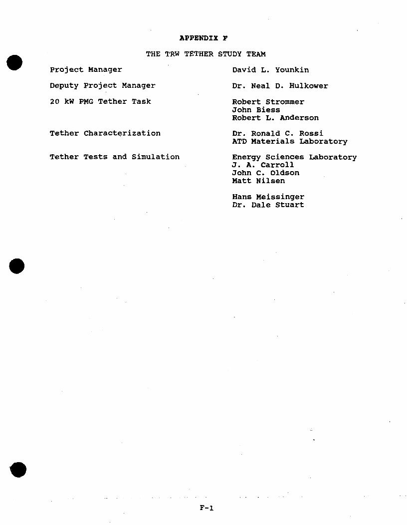
Project Manager
Deputy Project Manager
20 kW PMG Tether Task
Tether Characterization
Tether Tests and Simulation
APPENDIX F
THE TRW TETHER STUDY TEAM
David L. Younkin
Dr. Neal D. Hulkower
Robert StrommerJohn BiessRobert L. Anderson
Dr. Ronald C. RossiATD Materials Laboratory
Energy Sciences LaboratoryJ. A. CarrollJohn C. OldsonMatt Nilsen
Hans MeissingerDr. Dale Stuart
F-i


![Tether anthony[1]](https://static.fdocuments.net/doc/165x107/557c7d36d8b42a494c8b5161/tether-anthony1.jpg)