![Free-standing graphene films embedded in epoxy resin with enhanced thermal … · 2020-03-21 · ofthe pure epoxy resin.Yi Wang [8] outlined that the thermal conductivity of the epoxy](https://static.fdocuments.net/doc/165x107/5fb4caffabd6f51d5367cfc5/free-standing-graphene-films-embedded-in-epoxy-resin-with-enhanced-thermal-2020-03-21.jpg)
Study of Physical and Thermal Behaviour of Epoxy ...
34
Study of Physical and Thermal Behaviour of Epoxy Composites filled with Blast Furnace Slag A Project Report Submitted in Partial Fulfillment of the Requirements for the Degree of B. Tech. (Mechanical Engineering) By SUVENDHU KUMAR PATRA Roll No. 109ME0403 Under the supervision of Dr. Alok Satapathy Associate Professor Department of Mechanical Engineering, NIT, Rourkela Department of Mechanical Engineering NATIONAL INSTITUTE OF TECHNOLOGY ROURKELA MAY, 2013
Transcript of Study of Physical and Thermal Behaviour of Epoxy ...

Study of Physical and Thermal Behaviour of Epoxy Composites filled with Blast Furnace Slag
A Project Report Submitted in Partial Fulfillment of the Requirements for the Degree of
B. Tech.
(Mechanical Engineering)
By
SUVENDHU KUMAR PATRA
Roll No. 109ME0403
Under the supervision of
Dr. Alok Satapathy
Associate Professor
Department of Mechanical Engineering, NIT, Rourkela
Department of Mechanical Engineering
NATIONAL INSTITUTE OF TECHNOLOGY
ROURKELA
MAY, 2013

National Institute of Technology
Rourkela
C E R T I F I C A T E
This is to certify that the work in this thesis entitled “Study of physical and Thermal Behaviour of Epoxy Composites filled with Blast Furnace Slag” by
Suvendhu Kumar Patra, has been carried out under my supervision in partial
fulfillment of the requirements of the degree of Bachelor of Technology in
Mechanical Engineering session of 2012 - 2013 in the department of
Mechanical Engineering at National Institute of Technology, Rourkela.
To the best of my knowledge, this work has not been submitted to any other
University/ Institute for the award of any degree or diploma.
Dr. Alok Satapathy
(Supervisor)
Associate Professor Dept. of Mechanical Engineering National Institute of Technology
Rourkela - 769008

A C K N O W L E D G E M E N T
It is with my utmost sincerity that I express my deep sense of gratitude and respect
to my supervisor Prof. Alok Satapathy for his excellent guidance, meticulous
suggestions and impeccable support throughout the project. I consider myself
extremely worthy enough to work under the guidance of such a dynamic person. I
am also thankful to Prof. K.P. Maity, H.O.D, Department of Mechanical
Engineering, NIT Rourkela for his constant support and encouragement.
Last but not the least, I extend my sincere extolment to all other faculty members,
my senior research fellowmen and friends at the Department of Mechanical
Engineering, NIT Rourkela, for their help and valuable advice in every stage of
successful completion of this project.
Date: 12/5/2013 SUVENDHU KUMAR PATRA
NIT ROURKELA Roll No. 109ME0403
Department of Mechanical Engineering

B.Tech Thesis 2013
Department of Mechanical Engineering, NIT Rourkela Page 4
C O N T E N TS
Page No
ABSTRACT 5
LIST OF TABLES AND FIGURES 6
Chapter 1 Introduction 7-11
Chapter 2
Literature Review
12-14
Chapter 3
Materials and Methods
15-23
Chapter 4 Chapter 5
Results and Discussion
Conclusions
24-30
31-32
REFERENCES 33-34
B.Tech Thesis 2013
Department of Mechanical Engineering, NIT Rourkela Page 5
ABSTRACT
Blast furnace slag is a major industrial waste generated in huge quantities during extraction of
iron from its ores. Today eliminating, reducing or recycling waste is a major environmental
remediation technique used to manage health and ecological risks. This paper aims at studying
physical and thermal behaviour of epoxy composites filled with industrial waste in the form of
blast furnace slag. It is already being used in concrete mixtures, soil stabilization, and metal
matrix applications along with continuous research being pushed in for identifying more usage.
Hence in coherence, this paper aims at exploring the possibility of BF slag’s ability in
manufacturing composites that can improve certain mechanical properties and becomes a
possible low cost substitution to other composites. Resulting composite in this procedure has
been found to have improved thermal conductivity.
Keywords: Polymer Composites, Blast Furnace Slag, Epoxy, Thermal conductivity
B.Tech Thesis 2013
Department of Mechanical Engineering, NIT Rourkela Page 6
LIST of TABLES & FIGURES
TABLE 1 Composition for mold fabrication
TABLE 2 Thermal conductivity for composites obtained from FEM and Experiment
TABLE 3 Percentage errors associated with the FEM simulated values with respect to the
measured values (for blast furnace slag filled epoxy composites)
Fig 1 Classification of composites
Fig 2 Classification of polymer matrix composites
Fig 3 Determination of Thermal Conductivity Using Unitherm™ Model 2022
Fig 4 Cube in Cube model
Fig.5 Boundary conditions
Fig 6Temperature profile for BF slag filled epoxy composite of 1.4 % filler concentration
Fig 7 Temperature profile for BF slag filled epoxy composite of 3.35 % filler concentration
Fig 8 Temperature profile for BF slag filled epoxy composite of 5.25 % filler concentration
Fig 9 Temperature profile for BF slag filled epoxy composite of 7.85 % filler concentration
Fig 10: Temperature profile for BF slag filled epoxy composite of 9.4 % filler concentration
Fig 11Comparision of effective K of Sphere-in–cube & Cube-in–cube arrangement
Fig 12 Comparison of numerical, theoretical and experimental values

B.Tech Thesis 2013
Department of Mechanical Engineering, NIT Rourkela Page 7
CHAPTER 1 INTRODUCTION

B.Tech Thesis 2013
Department of Mechanical Engineering, NIT Rourkela Page 8
1. INTRODUCTION
Composite Materials
Composite materials (or composites) are materials that are made from two or more structural
units or constituents with largely different physical and chemical properties, which when
combined produce a material with attributes different from the individual structural units and
distinctive in the final structure. Of natural or synthetic ones, structural units comprise of the
matrices and reinforcement structures. The binder or matrix holds the reinforcements in an
orderly fashion. As the reinforcements are usually discontinuous it assists in load transfer among
the reinforcements. The reinforcement adds it special mechanical and physical properties
generating structures with superior properties, hence giving an upper hand over conventional
monolithic materials and a large degree of freedom in designing products or even when
optimizing a design. General applications have been building structures, bridges, boat hull
structures, shower stalls, bathtubs, storage tanks, race car (carbon fiber bodies) etc.
Types of Composite Materials
Fig 1: Classification of composites
B.Tech Thesis 2013
Department of Mechanical Engineering, NIT Rourkela Page 9
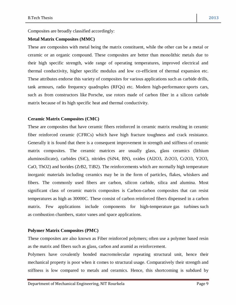
Composites are broadly classified accordingly:
Metal Matrix Composites (MMC)
These are composites with metal being the matrix constituent, while the other can be a metal or
ceramic or an organic compound. These composites are better than monolithic metals due to
their high specific strength, wide range of operating temperatures, improved electrical and
thermal conductivity, higher specific modulus and low co-efficient of thermal expansion etc.
These attributes endorse this variety of composites for various applications such as carbide drills,
tank armours, radio frequency quadruples (RFQs) etc. Modern high-performance sports cars,
such as from constructors like Porsche, use rotors made of carbon fiber in a silicon carbide
matrix because of its high specific heat and thermal conductivity.
Ceramic Matrix Composites (CMC)
These are composites that have ceramic fibers reinforced in ceramic matrix resulting in ceramic
fiber reinforced ceramic (CFRCs) which have high fracture toughness and crack resistance.
Generally it is found that there is a consequent improvement in strength and stiffness of ceramic
matrix composites. The ceramic matrices are usually glass, glass ceramics (lithium
aluminosilicate), carbides (SiC), nitrides (SiN4, BN), oxides (Al2O3, Zr2O3, Cr2O3, Y2O3,
CaO, ThO2) and borides (ZrB2, TiB2). The reinforcements which are normally high temperature
inorganic materials including ceramics may be in the form of particles, flakes, whiskers and
fibers. The commonly used fibers are carbon, silicon carbide, silica and alumina. Most
significant class of ceramic matrix composites is Carbon-carbon composites that can resist
temperatures as high as 30000C. These consist of carbon reinforced fibers dispensed in a carbon
matrix. Few applications include components for high-temperature gas turbines such
as combustion chambers, stator vanes and space applications.
Polymer Matrix Composites (PMC)
These composites are also known as Fiber reinforced polymers; often use a polymer based resin
as the matrix and fibers such as glass, carbon and aramid as reinforcement.
Polymers have covalently bonded macromolecular repeating structural unit, hence their
mechanical property is poor when it comes to structural usage. Comparatively their strength and
stiffness is low compared to metals and ceramics. Hence, this shortcoming is subdued by

B.Tech Thesis 2013
Department of Mechanical Engineering, NIT Rourkela Page 10
reinforcement of other constituent materials like ceramics or organic compounds. Low pressure
and temperature require whether the polymer is a thermoset (processing temperature 200°C) or a
thermoplastic (processing temperature 300°C to 400°C) along with simpler manufacturing
equipment for fabrication of these composites are subject to its usage in real-life applications.
Polymer Matrix Composites can again be further classified into three groups on the basis of
reinforcement material used.
Fig 2: Classification of polymer matrix composites
Particle
reinforced
Fiber
reinforced
Structural
Composites
Large-
particle
Micro
sized
Particle
Continuous
(Aligned)
Discontinuous
(Short)
Laminate
Sandwich
panels
Aligned
Randomly
Oriented

B.Tech Thesis 2013
Department of Mechanical Engineering, NIT Rourkela Page 11
BLAST FURNACE SLAG:
Background
Blast Furnace slag is a type of solid industrial waste of iron and steel making process in which
when iron ore or pellets, coke and flux (limestone or dolomite) are melted together in a blast
furnace. As the metallurgical smelting process is complete, the lime in the flux has chemically
combines with the aluminates and silicates of the ore and coke ash to form a non-metallic
product. The chemical composition of a slag varies considerably depending on the burden
chemistry of the raw materials in the production process. Silicate and aluminate impurities from
the ore and coke are combined in the blast furnace with a flux which reduces the viscosity of the
slag. In the case of pig iron production the flux mostly contains a mixture
of limestone and forsterite or in some cases dolomite. In the blast furnace the slag floats on top
of the iron and is poured for separation. Slow cooling of slag melts results in an unreactive
crystalline material consisting of Ca-Al-Mg silicates. To obtain a good slag reactivity, the slag
melt needs to be rapidly cooled or quenched below 800 °C in order to prevent the crystallization
of merwinite and melilite. To cool and fragment the slag a granulation process can be applied in
which molten slag is subjected to jet streams of water or air under pressure. Alternatively, in the
pelletization process the liquid slag is partially cooled with water and subsequently projected into
the air by a rotating drum. In order to obtain a suitable reactivity, the obtained fragments are
ground to reach the same fineness as Portland cement.
The chemical composition of BF slag for Indian conditions varies in the following range.
Calcium Oxide (CaO): 31%- 40%
Silicon Dioxide (SiO2): 29%-38%
Aluminium Oxide (Al2O3): 14%-22%
Magnesium Oxide (MgO): 7%-11%
Ferrous oxide (FeO): 0.1%-1.9%
Manganese Oxide (MnO): 0.01%-1.2%
Sulphur: 1%-1.9%
Basicity (CaO/ SiO2): 0.90%-1.3%

B.Tech Thesis 2013
Department of Mechanical Engineering, NIT Rourkela Page 12
CHAPTER 2 LITERATURE REVIEW

B.Tech Thesis 2013
Department of Mechanical Engineering, NIT Rourkela Page 13
2. LITERATURE REVIEW
Industrial waste today, produced from any industrial activity, major or minor, from factories,
mines or mills has been a major environmental concern. Waste management and recycling
processes have been major remediation techniques of the century to nullify health and ecological
risks. In this context, slag happens to be a major vitreous industrial by-product of the smelting
ore process. Slag generally contains metal oxides and silicon dioxide and also can contain metal
sulfides and atoms in the elemental form. Major slag such as Blast furnace slag is formed when
iron ore, coke and flux (either limestone or dolomite) are melted together in a blast furnace. As
the smelting process is complete, the lime in the flux chemically combines with the aluminates
and silicates of the ore and coke ash to form the non-metallic byproduct. While copper slag is
generated of the granulated slag of copper refineries, red mud is the solid waste product of the
Bayer process, the means to refine bauxite in generating alumina. These smelting processes
produce large volume of non-metallic dust and soot with red mud bearing the ability to be a
major environmental hazard among the three varieties of slags. However waste elimination
techniques have been the savior to an extent as evident from the various solid waste reusable
applications. Red mud for instance has been used in aluminium metal matrix composites for
wear resistance applications, along with studies of tribological properties [1, 2] that have
successfully cut part of the wastage. Red mud composite coatings [3] have improved wear
resistance. Similarly synergistic effect of copper slag and red mud happen to improve physical
and mechanical properties of bamboo fiber reinforced composites [4]. Again Biswas and
Satpathy [5] justified the possible utilization of copper slag as filler material for the preparation
of composite materials and value added products such as abrasive and cutting tools and railroad
ballast. Also as copper slag is highly stable and non-leachable, it is boasted of as an alternative
material for concrete applications which is evident from Sterlite Industries India’s recent stake in
waste management. Various copper matrix composite materials strengthened with alumina
particulates are engineered by means of pressure molding and sintering. The compactness of
composites increased with the sintering temperature and increase in pressure, and decreased with
the alumina content increasing. The hardness of composite materials increased with the increase
of sintering temperature, pressure and alumina particulates [6]. Among all slags discussed in this
paper, blast furnace (BF) slag is quite the most consumed solid waste which is apparent from its
numerous numbers of usages. Jian Zhou, Shunzhi Qian et al [7] studied cementitious composites

B.Tech Thesis 2013
Department of Mechanical Engineering, NIT Rourkela Page 14
from blast furnace slag and limestone powder which have high compressive strength and
improved tensile strain capacity. For usage in construction purposes, Cheng and Chiu [8]
researched the usage of granulated BF slag as a filler material in making of geo-polymers. Of
diversified research work, remediation of chromium contaminated soils studied by O.A.B Hassan
[9] claims of stabilizing chromium contaminated soils by presence of iron slag in the resulting
leachate. In the present work focus has been in studying the ability of BF slag as a filler material.
As this is a relatively new area of study, groundbreaking work by Padhi and Satpathy [10] and
again Padhi et.al. [11] has emphasized on the erosion study of epoxy resins and hybrid epoxy
composites respectively filled with blast furnace slag. In both cases, impact velocity and blast
furnace slag content have been found to be major factors while dealing with the erosion study.
Following work, stresses on understanding more of physical and thermal behavior of epoxy
composites filled with BF slag.

B.Tech Thesis 2013
Department of Mechanical Engineering, NIT Rourkela Page 15
CHAPTER 3 MATERIALS & METHODS
B.Tech Thesis 2013
Department of Mechanical Engineering, NIT Rourkela Page 16
3. MATERIALS & METHODS
Matrix Material:
Epoxy LY 556 resin, chemically belongs to the epoxide family has been used as the matrix
material in the present work, procured from Ciba-Geigy India Ltd. Its common name is
Bisphenol-A-Diglycidyl-Ether. The low temperature curing epoxy resin (Araldite LY 556) and
the corresponding hardener (HY 951) are mixed in a ratio of 10:1 by weight as recommended.
Epoxy is chosen primarily because it is the most commonly used polymer and because of its
insulating nature (low value of thermal conductivity, about 0.363 W/m-K) and low density (1.1
gm/cc).
Filler Material (Blast Furnace Slag):
In iron and steel making process, best practices produce around 300kg of slag/thm produced.
While bad practices produce 700-800 kg of slag/thm, major practices produce 500-600 kg of
slag/thm. Depending on cooling techniques, they are majorly granulated slag, air-cooled slag,
pellitized or expanded slag, the smaller gradation air cooled slag or the air cooled rip rap BF
slag. Density of ground granulated BF slag is in the range of 2.85-2.95 g/cm3. Thermal
conductivity of BF slag at room temperature is apparently 1.08 W/m K.
Composite Fabrication:
The low temperature curing epoxy resin (LY 556) and corresponding hardener (HY951) supplied
by Ciba Geigy India Ltd. are mixed in a ratio of 10:1 by weight as needed. Blast furnace slag
(avg. density of 2.85-2.95 gm/cc) with average size 100 μm is reinforced in epoxy resin (density
1.1 gm/cc) to prepare the composites. The dough (epoxy filled with blast furnace slag) is then
slowly poured into the moulds, coated beforehand with wax and uniform thin film of silicone
releasing agent for its excellent releasing characteristics. The composites are cast by established
hand-lay-up technique so as to get disc-shaped specimens. Composites of six different
compositions (of 1.4, 3.35, 5.23, 7.85, 9.4 and 11.3 vol. % of blast furnace slag respectively) are
made. The castings are left to cure at room temperature for about 24 hours and then moulds are
broken and samples are released to understand properties.
B.Tech Thesis 2013
Department of Mechanical Engineering, NIT Rourkela Page 17
Table 1: Composition for mold fabrication
THERMAL CHARACTERIZATION
Experimental Determination of Thermal Conductivity:
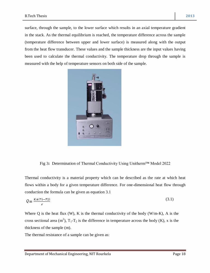
Unitherm™ Model 2022 is a thermal conductivity measuring instrument for a variety of
materials that includes polymers, ceramics, composites, rubbers, glasses few metals and
materials of thermal conductivity from low to medium range. It requires a small test sample only.
Non-solids like thin films can also be tested accurately employing a multi-layer technique. The
tests concur with the ASTM E-1530 standard.
Operating principle of UnithermTM
2022:
The sample is held under an uniform compressive load between two polished surfaces which
regulates the temperature of the two surfaces. The direction of heat flow is from the upper
Samples Composition
(for blast furnace slag filled epoxy)
1 Epoxy + 1.4 vol. % (1.05 wt %) Filler
2 Epoxy + 3.35 vol. % (2.51 wt %) Filler
3 Epoxy + 5.23vol. % (3.92 wt %) Filler
4 Epoxy + 7.85 vol. % (5.88wt %) Filler
5 Epoxy + 9.4 vol. % (7.05 wt %) Filler
6 Epoxy + 11.3 vol. % (8.48 wt %) Filler
B.Tech Thesis 2013
Department of Mechanical Engineering, NIT Rourkela Page 18
surface, through the sample, to the lower surface which results in an axial temperature gradient
in the stack. As the thermal equilibrium is reached, the temperature difference across the sample
(temperature difference between upper and lower surface) is measured along with the output
from the heat flow transducer. These values and the sample thickness are the input values having
been used to calculate the thermal conductivity. The temperature drop through the sample is
measured with the help of temperature sensors on both side of the sample.
Fig 3: Determination of Thermal Conductivity Using Unitherm™ Model 2022
Thermal conductivity is a material property which can be described as the rate at which heat
flows within a body for a given temperature difference. For one-dimensional heat flow through
conduction the formula can be given as equation 3.1
(3.1)
Where Q is the heat flux (W), K is the thermal conductivity of the body (W/m-K), A is the
cross sectional area (m2), T1-T2 is the difference in temperature across the body (K), x is the
thickness of the sample (m).
The thermal resistance of a sample can be given as:
B.Tech Thesis 2013
Department of Mechanical Engineering, NIT Rourkela Page 19
𝑅 =𝑇1−𝑇2
𝑄
𝐴
(3.2)
Where, R is the resistance of the sample between surfaces (upper and lower) (m2-K/W). From
Equations 3.1 and 3.2 we can derive that
𝐾 = 𝑥/𝑅 (3.3)
In Unithermtm
2022, the heat flux transducer measures the Q value and the temperature
difference is obtained between the upper and lower plate. Giving the input value of thickness of
the sample and the known cross sectional area, the effective thermal conductivity of the
composite samples can be calculated using Equation 3.3.
Numerical Analysis: Concept of Finite Element Method (FEM) and ANSYS:
The Finite Element Method (FEM) was introduced in 1956 by Turner et al. [12], which is a
powerful computational technique for approximate solutions in a variety of engineering
problems with complex domains subject to general boundary conditions. FEM has become a
major step in the modeling of a physical phenomenon in various engineering fields. As the field
variables vary from point to point, it results in an infinite number of solutions within the domain.
The basic concept of FEM lies in the segmentation of the domain into a finite number of sub
domains (the sample in finite number of elements) for which the systematic approximate solution
is constructed by applying either variational or weighted residual methods. FEM reduces the
problem into a finite number of unknowns by dividing the domain into elements and expresses
the unknown field variable in the form of assumed approximating functions within each element.
These functions are also known as interpolation functions. These functions define the values of
the field variables at specific points called nodes. Nodes connect adjacent elements. This method
has the ability to differentiate the irregular domains with finite elements for which it is a valuable

B.Tech Thesis 2013
Department of Mechanical Engineering, NIT Rourkela Page 20
and practical analysis tool for the solution of boundary or initial or eigen value problems arising
in various engineering fields.
Basic Steps in FEM:
The very first step is to convert the governing differential equation into an integral form.
The two techniques to achieve this are:
(i) Variational Technique
(ii) Weighted Residual Technique.
In variational technique, the integral form corresponding to the given differential equation is
obtained by using calculus of variation. The solution of the problem can be obtained by the
minimization of the integral. In weighted residual technique, the weighted integrals of the
governing differential equation are constructed where the weight functions are known and are
arbitrary except that they satisfy boundary conditions. Often this integral form is modified using
the divergence theorem to reduce the continuity requirement of the solution. Then solution is
obtained by setting the integral to zero.
The second step deals with the division of the domain of the problem into a number of parts,
called as elements. This process of division of the domain into a finite number of elements has
been known as mesh. For one-dimensional (1-D) problems, the elements are nothing but simple
line segments having no shape but only length. For problems for higher dimensions, the elements
have both the shape and size. For two-dimensional (2-D) or axi-symmetric problems, depending
on the type of meshing the elements used are triangles, rectangles and quadrilateral having either
straight or curved boundaries. For three-dimensional (3-D) problems, either tetrahedron or
parallelepiped elements are used having straight or curved surfaces.
In the third step, for the interpolation functions (also called as shape functions) a proper
approximation is chosen as the primary variable and the unknown values of the primary variable
B.Tech Thesis 2013
Department of Mechanical Engineering, NIT Rourkela Page 21
at some pre-selected points of the element, called as the nodes. Mostly polynomials are chosen as
the shape functions. For 1-D elements, there are at least 2 nodes placed at the endpoints of the
line segment. For 2-D and 3-D elements, the nodes are placed at the vertices. Additional nodes
are placed on the boundaries or in the interior. Degree of freedom is the value of the primary
variable at the nodes.
To get the exact solution, a complete set of polynomials (i.e., infinite term) should be in the
expression for the primary variable or if it contains only the finite terms, then the number of
elements will be infinite. Each of the above cases results into an infinite set of algebraic
equations. Only a finite number of elements and an expression with only finite number of terms
are used to make the problem tractable. The accuracy of the approximate solution, however, can
be improved either by increasing the number of elements or the number of terms in the
approximation.
In the fourth step, the primary variable of approximation is substituted in the integral form. It is
minimized to get the algebraic equations for the unknown nodal values if the integral form is of
variational type. The algebraic equations are obtained element wise first that is called the
element equation and then these element equations are assembled over all the elements to get the
algebraic equations for the whole domain (called as the global equation). Then the algebraic
equations are modified depending on the boundary conditions and the nodal values are obtained
by solving the modified algebraic equations.
Now the last step is the post-processing of the solution. Then, the nodal values are used to
construct their graphical variation over the domain either in the form of graphs or contours
depending on the dimensions and contours.

B.Tech Thesis 2013
Department of Mechanical Engineering, NIT Rourkela Page 22
Advantages of the finite element method over other numerical methods are as follows:
Any irregular-shaped domain or any type of boundary condition can be analyzed using
this method. Clearly reflects the benefits.
Analysis of domains consisting more than one material can be easily done.
With proper refinement of the mesh or by choosing higher degree polynomials the
accuracy of the solution can be improved majorly.
Analytical Model:
The effective thermal conductivity of the cube in cube model has been derived from the
existing sphere in cube model proposed by J.Z. Liang and G.S. Liu. The final expression of
this model is:-
𝑘𝑒𝑓𝑓 =𝑚
𝑚−1
𝑘𝑝+
𝑚2
𝑘𝑝 𝑚2−1 +𝑘𝑓
Fig 4: Cube in Cube model
B.Tech Thesis 2013
Department of Mechanical Engineering, NIT Rourkela Page 23
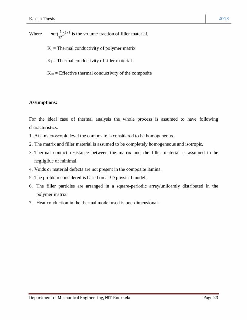
Where m=(1
ɸ𝑓)1/3 is the volume fraction of filler material.
Kp = Thermal conductivity of polymer matrix
Kf = Thermal conductivity of filler material
Keff = Effective thermal conductivity of the composite
Assumptions:
For the ideal case of thermal analysis the whole process is assumed to have following
characteristics:
1. At a macroscopic level the composite is considered to be homogeneous.
2. The matrix and filler material is assumed to be completely homogeneous and isotropic.
3. Thermal contact resistance between the matrix and the filler material is assumed to be
negligible or minimal.
4. Voids or material defects are not present in the composite lamina.
5. The problem considered is based on a 3D physical model.
6. The filler particles are arranged in a square-periodic array/uniformly distributed in the
polymer matrix.
7. Heat conduction in the thermal model used is one-dimensional.

B.Tech Thesis 2013
Department of Mechanical Engineering, NIT Rourkela Page 24
CHAPTER 4 RESULTS & DISCUSSION

B.Tech Thesis 2013
Department of Mechanical Engineering, NIT Rourkela Page 25
4. RESULTS AND DISCUSSION
Numerical Analysis
In the numerical analysis of the problem, the temperatures at the nodes of the surface ABCD is
prescribed as T1 (=1000C) and the convective heat transfer coefficient is assumed to be 2.5
W/m2-K at ambient temperature of 27°C. The heat flow direction and the boundary conditions
are shown in Fig. 4.1(heat flow from face ABCD to EFGH). The other surfaces are all assumed
to be adiabatic. The unknown temperatures at the nodes in the interior region and on the
adiabatic boundaries are obtained with the help of finite-element program package ANSYS.
Fig.5 Boundary conditions
B.Tech Thesis 2013
Department of Mechanical Engineering, NIT Rourkela Page 26
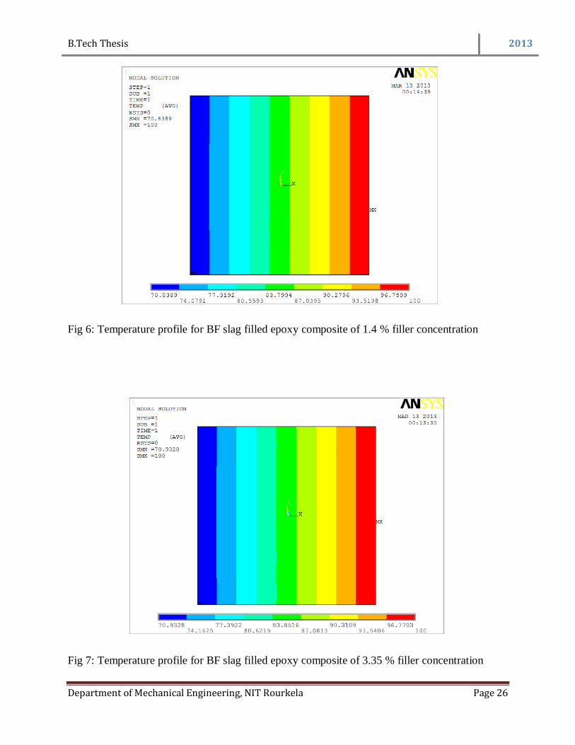
Fig 6: Temperature profile for BF slag filled epoxy composite of 1.4 % filler concentration
Fig 7: Temperature profile for BF slag filled epoxy composite of 3.35 % filler concentration

B.Tech Thesis 2013
Department of Mechanical Engineering, NIT Rourkela Page 27
Fig 8: Temperature profile for BF slag filled epoxy composite of 5.25 % filler concentration
Fig 9: Temperature profile for BF slag filled epoxy composite of 7.85 % filler concentration

B.Tech Thesis 2013
Department of Mechanical Engineering, NIT Rourkela Page 28
Fig 10: Temperature profile for BF slag filled epoxy composite of 9.4 % filler concentration
B.Tech Thesis 2013
Department of Mechanical Engineering, NIT Rourkela Page 29
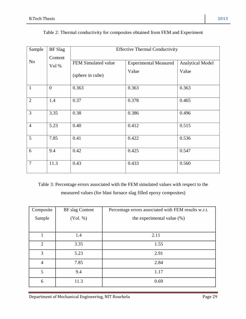
Table 2: Thermal conductivity for composites obtained from FEM and Experiment
Sample
No
BF Slag
Content
Vol %
Effective Thermal Conductivity
FEM Simulated value
(sphere in cube)
Experimental Measured
Value
Analytical Model
Value
1 0 0.363 0.363 0.363
2 1.4 0.37 0.378 0.465
3 3.35 0.38 0.386 0.496
4 5.23 0.40 0.412 0.515
5 7.85 0.41 0.422 0.536
6 9.4 0.42 0.425 0.547
7 11.3 0.43 0.433 0.560
Table 3: Percentage errors associated with the FEM simulated values with respect to the
measured values (for blast furnace slag filled epoxy composites)
Composite BF slag Content Percentage errors associated with FEM results w.r.t.
Sample (Vol. %) the experimental value (%)
1 1.4 2.11
2 3.35 1.55
3 5.23 2.91
4 7.85 2.84
5 9.4 1.17
6 11.3 0.69

B.Tech Thesis 2013
Department of Mechanical Engineering, NIT Rourkela Page 30
Fig.11.Comparision of effective K of Sphere-in–cube & Cube-in–cube arrangement
Fig.12. Comparison of numerical, theoretical and experimental values
0.35
0.4
0.45
0.5
0.55
0.6
1.4 3.35 5.23 7.85 9.4 11.3
keff (Sphere-in-cube model)
keff (Cube-in -cube model)
BF slag (vol%)
Eff
ecti
ve
ther
mal
co
nduct
ivit
y (
W/m
K)
0.35
0.4
0.45
0.5
0.55
0.6
1.4 3.35 5.23 7.85 9.4 11.3
keff ( theoretical model)
keff (Numerical model)
keff (Experimental)
BF slag (vol%)
Eff
ecti
ve
ther
mal
co
nduct
ivit
y (
W/m
K)

B.Tech Thesis 2013
Department of Mechanical Engineering, NIT Rourkela Page 31
CHAPTER 5 CONCLUSION
B.Tech Thesis 2013
Department of Mechanical Engineering, NIT Rourkela Page 32
5. CONCLUSION
Blast Furnace Slag-filled epoxy composites can be successfully manufactured by hand-lay-up
technique.
Inspite of being an industrial waste, BF-Slag can be used as a filler material in the epoxy
matrix.
Finite Element Method (FEM) can be gainfully employed to determine the effective
thermal conductivity (keff) of these particulate filled polymer composites for a wide
range of filler concentration of BF-Slag.
The values of the effective thermal conductivity (keff) obtained for various composite
models from FEM are in a very well approximation with the experimental values for a
wide range of filler concentration from 1.4 vol% to 11.3 vol%.
The embedment of Blast Furnace-Slag particle results in the improvement of thermal
conductivity of epoxy resin. With addition of 11.3 vol. % of filler content, the thermal
conductivity improves by about 19.28% with respect to neat epoxy resin and the error
percentages lie within a minimal range of 3 %

B.Tech Thesis 2013
Department of Mechanical Engineering, NIT Rourkela Page 33
REFERENCES:
1. Prasad Naresh & Acharya S.K; “Development of Metal Matrix Composite Using Red
mud an Industrial Waste for Wear Resistant Applications.” Proceedings of the
International Conference on Industrial Tribology, Mumbai, Dec.15-18, 2004, pp.164-170
2. Prasad Naresh & Acharya S.K; “Tribological Behaviour of Aluminium Red Mud
Composite.” Presented at the 12th International Conference on Solid Waste Technology
and Management, Philadelphia, USA, April 3-6, 2005.
3. Sutar, H., Mishra, S. , Sahoo, S. , Satapathy, A. and Kumar, V. (2012) Morphology and
solid particle erosion wear behavior of red mud composite coatings. Natural Science, 4,
832-838. doi: 10.4236/ns.2012.411111.
4. Sandhyarani Biswas, Amar Patnaik, and Ritesh Kaundal, “Effect of Red Mud and Copper
Slag Particles on Physical and Mechanical Properties of Bamboo-Fiber-Reinforced
Epoxy Composites,” Advances in Mechanical Engineering, vol. 2012, Article ID 141248,
6 pages, 2012. doi:10.1155/2012/141248
5. Biswas S, Satapathy A “Use of copper slag in glass-epoxy composites for improved wear
resistance”. Waste Manag Res. 2010 Jul;28(7):615-25. doi: 10.1177/0734242X09352260.
Epub 2009 Nov 26.
6. Wei Ping Liu, 2011, “Use Copper Slag to Prepare Copper Matrix Composites” Advanced
Materials Research, 183-185, 1586.
7. Jian Zhou, Shunzhi Qian, M. Guadalupe Sierra Beltran, Guang Ye, Klaas van Breugel,
Victor C. Li “Development of engineered cementitious composites with limestone
powder and blast furnace slag”. Materials and Structures , Springer Link July
2010, Volume 43, Issue 6, pp 803-814.
8. T W Cheng, J P Chiu “Fire-resistant geo polymer produced by granulated blast furnace
slag”. Minerals Engineering 16 (2003) 205–210, Pergamon.
9. O A B Hassan, “Remediation of Chromium contaminated soil using blast furnace slag”.
Int. J. Sus. Dev. Plann. Vol. 6, No. 1 (2011) 81–90.

B.Tech Thesis 2013
Department of Mechanical Engineering, NIT Rourkela Page 34
10. Prasanta Kumar Padhi, Alok Satpathy, “Parametric Evaluation of Erosion Response of
Epoxy Resin filled with blast furnace slag using Taguchi technique”. International
Conference on "Advancements in Polymeric Materials", APM 2012, February 10 -12,
2012, CIPET Ahmedabad .
11. Prasanta Kumar Padhi, Alok Satpathy, Srimant Kumar Mishra, Sisir Mantry, “Erosive
wear behavior of Glass-Epoxy hybrid composites reinforced with blast furnace slag”.
International Conference on "Advancements in Polymeric Materials", APM 2012,
February 10 -12, 2012, CIPET Ahmedabad.
12. M. J. Turner, R. W. Clough, H. C. Martin and L. J. Topp, Stiffness and Deflection
Analysis of Complex Structures, J. of the Aeronautical Sciences, 23 (1956) 805-823.


![Prediction of the Enhanced Out-of-Plane Thermal Conductivity ...tride nanoparticles in epoxy composites [5]. Hong [4] et al. enhanced the thermal con-ductivity of epoxy composites](https://static.fdocuments.net/doc/165x107/60ee5ed6898096425f1dcc69/prediction-of-the-enhanced-out-of-plane-thermal-conductivity-tride-nanoparticles.jpg)


