Study of Creep Embrittlement of 2-1/4Cr-1Mo Steel Weld...
12
Study of Creep Embrittlement of 2-1/4Cr-1Mo Steel Weld Metal Creep embrittlement of 2-1/4Cr-1Mo steel weld metal may result from non-equilibrium segregation of residual elements in prior austenite grain boundaries BY R. A. SWIFT AND H. C. ROGERS ABSTRACT. A study of the effects of postweld heat treatment variations on the mechanical properties of a multi- pass submerged arc weld of 2-1/4 Cr- 1 Mo steel confirms that three types of embrittlement can occur. These are postweld heat treatment embrittle- ment by precipitation hardening, temper embrittlement, and creep em- brittlement. In a previous paper, the mechanism of postweld heat treat- ment embrittlement by precipitation hardening has been identified. In this present work, creep embrittlement by non-equilibrium segregation of residual elements in prior austenite grain boundaries is identified. The three types of embrittlement are interrelated although their mechanisms are different. Postweld heat treatment embrittlement and temper embrittlement can occur simultaneously and both can reduce creep rupture ductility. However, if a weld is temper embrittled prior to creep, the rupture ductility is im- proved. This interaction is consistent with the mechanism of temper em- brittlement involving non-equilibrium segregation of residual elements proposed by Rellick and McMahon. Fractographic studies of creep voids and low temperature brittle fractures of weld metal tested in creep show that low temperature inter- granular fracture typical of temper embrittlement is accentuated by creep exposure. R. A. SWIFT is a research engineer at Lukens Steel Co., Coatesville, Pa. 19320. H. C. ROGERS is professor of metal- lurgical engineering, Drexel University, Philadelphia, Pa. 19104. Paper was presented at the 56th AWS Annual Meeting held at Cleveland, Ohio, April 21-25, 1976. Introduction Whenever metals creep, the danger of fracture exists. The duc- tility at fracture can be either high or low depending upon the conditions of stress and temperature. Creep em- brittlement is a phenomenon that gives rise to unexpectedly low duc- tility fractures. It has been observed in low alloy steels (Refs. 1-4), stainless steels (Refs. 1, 5), and carbon steels with a high concentration of active nitrogen (Ref. 1). One definition of creep embrittlement is a minimum in the curve of rupture ductility as a function of the time to rupture. The rupture ductility decreases with time to rupture as the degree of inter- granular cavitation increases (Refs. 1, 2, 6-9). The subsequent increase in rupture ductility after a minimum value has been associated with the formation of a denuded zone adjacent to the grain boundaries (Refs. 1, 2, 10- 12) or a decrease in the strength of the matrix upon the precipitation of stable carbides (Refs. 3, 9). Pickering (Ref. 9) has suggested that precipitate stability has a marked effect on creep ductility. If carbide formers are retained in stable car- bides and thus effectively prevented from strengthening the matrix by solid solution strengthening, the strength of the matrix can be lower than the strength of the grain boundaries. Ap- preciable deformation can then occur within the grains prior to grain bound- ary deformation. Since grain bound- ary strain is often accompanied by cavitation, creep ductility can be high when stable precipitates form in the matrix. Ferrell and Pense (Ref. 3) in their study of 2-1/4 Cr-1 Mo steel plate have shown that precipitate strengthening of the matrix can also cause creep embrittlement. Creep ductility improves with overaging of the precipitates. Grain size effects are critical in welds because of the wide range of grain sizes found. In 2-1/4 Cr-1 Mo steel the prior austenite grain size has a marked effect upon rupture ductility with no effect on the rupture life (Ref. 13). Intergranular voids may form in coarse grained regions after small creep deformation that would not be detrimental in a fine grained structure. As a result of this early void formation, a low ductility failure of the weldment could occur. Numerous tests on Cr-Mo steels have shown the effects of strength level on rupture ductility (Refs. 2, 4, 14-19). Data have been reported for plate steel at strength levels up to 149 ksi and for weld metal in the as-weld- ed, stress relieved, and quenched and tempered conditions at strength levels up to 134 ksi. For tests pro- ducing comparable rupture times, the rupture ductility decreases and magnitude of the loss in ductility due to creep embrittlement increases with increasing strength above 130 ksi. At tensile strengths below 130 ksi the effect of strength level on rupture ductility is less pronounced. Purity is an important factor in de- termining the magnitude of creep em- brittlement. It is believed that impur- ities such as arsenic, antimony, phos- phorus and tin reduce rupture duc- tility by a mechanism similar to that of classical temper embrittlement (Refs. 5, 11, 18). In summary, creep ductility is in- fluenced by many factors. Strength, grain size, degree of solid solution strengthening and precipitate mor- phology contribute to creep em- brittlement. For maximum ductility, a 188-8 I JULY 1976
Transcript of Study of Creep Embrittlement of 2-1/4Cr-1Mo Steel Weld...
Study of Creep Embrittlement of 2-1/4Cr-1Mo Steel Weld Metal
Creep embrittlement of 2-1/4Cr-1Mo steel weld metal may result from non-equilibrium segregation of residual elements in prior austenite grain boundaries
BY R. A. SWIFT AND H. C. ROGERS
ABSTRACT. A study of the effects of postweld heat treatment variations on the mechanical properties of a multipass submerged arc weld of 2-1/4 Cr-1 Mo steel confirms that three types of embritt lement can occur. These are postweld heat treatment embritt lement by precip i tat ion hardening, temper embritt lement, and creep embrittlement. In a previous paper, the mechanism of postweld heat treatment embritt lement by precipitation hardening has been identified. In this present work, creep embritt lement by n o n - e q u i l i b r i u m s e g r e g a t i o n of residual elements in prior austenite grain boundaries is identified.
The three types of embritt lement a re i n t e r r e l a t e d a l t h o u g h the i r mechanisms are different. Postweld heat treatment embritt lement and temper embr i t t lement can occur simultaneously and both can reduce creep rupture ductility. However, if a weld is temper embritt led prior to creep, the rupture ductility is improved. This interaction is consistent with the mechanism of temper embrittlement involving non-equil ibrium segregat ion of residual elements proposed by Rellick and McMahon.
Fractographic studies of creep voids and low temperature brittle fractures of weld metal tested in creep show that low temperature intergranular fracture typical of temper embr i t t lement is accentuated by creep exposure.
R. A. SWIFT is a research engineer at Lukens Steel Co., Coatesville, Pa. 19320. H. C. ROGERS is professor of metallurgical engineering, Drexel University, Philadelphia, Pa. 19104.
Paper was presented at the 56th AWS Annual Meeting held at Cleveland, Ohio, April 21-25, 1976.
Introduction
Whenever metals creep, the danger of fracture exists. The ductility at fracture can be either high or low depending upon the conditions of stress and temperature. Creep embrittlement is a phenomenon that gives rise to unexpectedly low ductility fractures. It has been observed in low alloy steels (Refs. 1-4), stainless steels (Refs. 1, 5), and carbon steels with a high concentration of active nitrogen (Ref. 1). One definition of creep embritt lement is a minimum in the curve of rupture ductility as a function of the time to rupture. The rupture ductility decreases with t ime to rupture as the degree of intergranular cavitation increases (Refs. 1, 2, 6-9). The subsequent increase in rupture ductility after a minimum value has been associated with the formation of a denuded zone adjacent to the grain boundaries (Refs. 1, 2, 10-12) or a decrease in the strength of the matrix upon the precipitation of stable carbides (Refs. 3, 9).
Pickering (Ref. 9) has suggested that precipitate stability has a marked effect on creep ductility. If carbide formers are retained in stable carbides and thus effectively prevented from strengthening the matrix by solid solution strengthening, the strength of the matrix can be lower than the strength of the grain boundaries. Appreciable deformation can then occur within the grains prior to grain boundary deformation. Since grain boundary strain is often accompanied by cavitation, creep ductility can be high when stable precipitates form in the matrix. Ferrell and Pense (Ref. 3) in their study of 2-1/4 Cr-1 Mo steel plate have shown that precipitate strengthening of the matrix can also
cause creep embritt lement. Creep ductility improves with overaging of the precipitates.
Grain size effects are critical in welds because of the wide range of grain sizes found. In 2-1/4 Cr-1 Mo steel the prior austenite grain size has a marked effect upon rupture ductility with no effect on the rupture life (Ref. 13). Intergranular voids may form in coarse grained regions after small creep deformation that would not be detrimental in a fine grained structure. As a result of this early void formation, a low ductility failure of the weldment could occur.
Numerous tests on Cr-Mo steels have shown the effects of strength level on rupture ductility (Refs. 2, 4, 14-19). Data have been reported for plate steel at strength levels up to 149 ksi and for weld metal in the as-welded, stress relieved, and quenched and tempered conditions at strength levels up to 134 ksi. For tests producing comparable rupture times, the rupture ductility decreases and magnitude of the loss in ductility due to creep embritt lement increases with increasing strength above 130 ksi. At tensile strengths below 130 ksi the effect of strength level on rupture ductility is less pronounced.
Purity is an important factor in determining the magnitude of creep embrittlement. It is believed that impurities such as arsenic, antimony, phosphorus and tin reduce rupture ductility by a mechanism similar to that of classical temper embritt lement (Refs. 5, 11, 18).
In summary, creep ductility is influenced by many factors. Strength, grain size, degree of solid solution strengthening and precipitate morphology cont r ibute to creep embrittlement. For maximum ductility, a
188-8 I J U L Y 1 9 7 6
normal ized and tempered micro-structure is general ly preferable; never the less , for g rea ter c reep strength a quenched and tempered or welded plus stress relieved micro-structure might be more desirable. In a weldment, the multiplicity of micro-structures makes it difficult to predict low creep rupture ductility. The variety of grain sizes and temper ing gradients caused by subsequent weld passes results in need for a more critical evaluation of factors affecting creep ductility.
Experimental Procedures
Welding
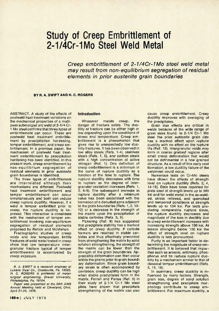
The weld used in this study was a tandem head submerged arc weld of 2-1/4 Cr-1 Mo steel. It was deposited in a 2-1/4 in. gage plate with a double-V 90 deg included angle joint configuration. The plates were preheated to 200 F prior to welding. An interpass temperature of 350 F was ma in tained. The welding parameters were selected to supply 45.2 kJ/ in. to the lead head and 46.5 kJ/ in . to the trail head. The weldments were post weld soaked at 250 F for a minimum of 40 h to prevent hydrogen cracking. Figure 1a shows a macrosection of the weld. The composit ion of the filler metal and weld deposit are given in Table 1. It should be noted that the concentrations of t ramp elements are lower than normal while that of copper is above average.
Material Processing
The weld was oxygen cut from each plate to simplify handling; 2-1/2 in. on each side of the centerline of the weld was removed from the plates. Heat treatments were performed on weldments 2-1/4 X 5 in. X the desired length.
The welds were given a variety of nonstandard postweld heat t reatm e n t s (PWHT) to e x a m i n e the response of the weld to temperatures over a much broader range than normally employed by industry. Temperatures of 900, 1100 and 1300 F for 4-1/2 h were used. Commercial practice for 2-1/4 Cr-1 Mo steel weldments, specified by the ASME Boiler Code (Ref. 20), requires a minimum treatment of 1250 F for one hour per inch of thickness. The two hours per inch of thickness PWHT time used in this study was selected because of toughness consideratons. In a previous paper (Ref. 21), it was shown that this treatment accentuates PWHT embrittlement. The maximum effects of PWHT could be assessed using this approach.
Weld metal, in the as-deposited and a variety of PWHT conditions was step cooled to induce temper em
brittlement. Step cooling generally accelerates temper embr i t t lement and is used to approximate the effects of long t ime isothermal aging. Specimens are heated to approximately 1100 F and then subject to a series of isothermal aging treatments at successively lower temperatures to approximately 850 F. After the final aging treatment, the material is furnace cooled to 600 F, then air cooled to room temperature. The step cooling cycle used in this study is given in Table 2.
Preliminary mechanical testing included Charpy V-notch (CVN) impact and room temperature tension tests to determine the effects of PWHT and step cooling on the notch toughness, strength, and ductility of 2-1/4 Cr-1 Mo steel weld metal. All specimens
Table 1 — Chemical Analysis of Filler Metal and Submerged Arc Weld Deposit, Wt%(a»
Element
C Mn P S Si Cu Ni Cr Mo V Ti Al
N O H As Sb Sn
soluble nsoluble
Total
Filler metal
0.060 0.59 0.006 0.019 0.19 0.58 0.08 2.70 0.96 0.01 0.005 0.005 0.055 0.060 0.011
6 1 ( b )
2.9(b) 0.004 0.0005 0.002
Deposit
0.055 0.82 0.008 0.021 0.37 0.51 0.086 2.50 0.99 0.01 0.005 0.012 0.001 0.013 0.016
694 ( b )
— 0.005 0.0009 0.005
(a) Analysis courtesy of Dr. W. D. Doty. U.S. Steel Applied Research Laboratories. MonroeviHe. Pennsylvania (b) Parts per million
were cut from the quarterline. The CVN specimens were cut transverse to the weld axis and notched perpendicular to the weld surface. The tensile specimens, 0.505 in. diam, were cut parallel to the weld axis. Figures 1b and 1c show the location of test specimens in the weld.
Creep-Rupture Test Program
Creep-rupture tests were initially performed at 1100 F because it is at the upper end of the temperature range known to cause PWHT embrittlement, temper embritt lement, and creep embritt lement in plate steel. Also, interact ions between these embritt lements could be evaluated in relatively short t ime tests.
To clarify the interactions between the three types of embritt lement, as-
X i t
k
w h
Fig. 1 — Macro section of weld (a) and location of Charpy V-notch impact specimens (b) and threaded-end 0.505 in diam tensile specimens (c)
Table 2 — Room Temperature Tensile Properties
Treatment
As deposited As deposited
plus step cool (a)
900F/4V2 hours 900F/4'/2 hours
plus step cool 1100F/4V2 hours 1300F/4V4 hours 1300F/4V2 hours
plus step cool
(a)
(a)
.2% Yield strength,
ksi
107.3 116.7
112.5 89.0
104.2 66.2 67.5
Ultimate tensile
strength, ksi
130.7 126.0
131.8 102.4
117.6 82.5 84.6
% Red. in area
41.8 43.3
43.0 56.9
44.6 67.0 65.5
% Elong. in 2 in.
15.0 16.5
16.8 18.5
16.0 25.8 25.5
(a) 1080 F. hold 1 h — FC to 1040 F, hold 14 h — FC to 980 F, hold 33 h — FC to 930 F, hold 80.5 h — FC to 860 F. hold 76.5 h — FC to 600 F — AC
WELDING RESEARCH S U P P L E M E N T ! 189-8
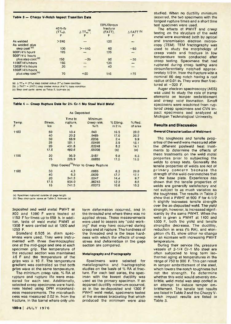
Table 3 — Charpy V-Notch Impact Transition Data
As welded As welded plus
step cool (c)
900F/4'/2 hours 900F/4V2 hours
plus step cool< c )
1100F/4V4 hours 1300F/4V4 hours 1300F/4V4 hours
plus step cool< c )
40 ft-lb (TT40),
F
>240
130 185
150 195 20
70
ATTJ3! F
> —110
—
- 3 5
— —
+ 50
50% fibrous fracture (FATT),
F
120
60 125
95 130 40
115
A FATT <b> F
- 6 0
—
- 3 0
— —
+ 75
(a) A TT«o = (TTM) step cooled minus (TT«) base condition (b) A FATT = (FATT) step cooled minus (FATT) base condition (c) Step cool cycle: same as Table 2, footnote (a)
Table 4 — Creep Rupture Data for 21/» Cr-1 Mo Steel Weld Metal
Temp. F
1100
1150
1100
Stress, ksi
50 40 30 25 20
17.5
20 15
As Deposited
Time to rupture,
h
10.4 20.2 68.9
181.1 431.8 482.6
95.9 226.9
Step Cooled<b)Prior
50 40 20
17.5 15
4.3 6.3
341.3 604.0 741.5
Minimum creep rate,
%/h
.040
.0465
.0206
.00495
.00248
.00208
.0187
.00655
to Creep Rupture
.0865
.0639
.0047
.00213
.00373
% Elong. in 2 in.
16.5 17.0 2.4 3.9 8.2 (a)
9.8 17.5
8.3 17.7 14.4 12.2 10.8
% Red. of area
29.0 20.2
9.9 18.1 14.1 (a)
6.3 11.5
29.0 17.1 9.7 8.5
15.3
(a) Specimen ruptured outside of gage length (b) Step cool cycle: same as Table 2. footnote (a)
deposited and weld metal PWHT at 300 and 1300 F were tes ted at 1150 Ffor times up to 550 h. In addition, tests of weld metal PWHT at 1300 F were carried out at 1200 and 1250 F.
Standard 0.505 in. d iam specimens were used. They were instrumented with three thermocouples: one at the mid-gage and one at each specimen grip. The temperature of the reduced section was maintained ± 5 F and the temperature of the grips was ± 10 F. The temperature gradient was controlled so that both grips were at the same temperature.
The minimum creep rate, % RA at rupture and rupture life were measured for each test. Addi t ional ly, selected creep specimens were hardness tested using DPH microhardness measurements. The microhardness was measured 0.02 in. from the fracture, in the barrel where only uni
form deformation occurred, and in the threaded end where there was no applied stress. These measurements were used to assess any "cold working" that may have occurred during creep and at rupture. The hardness of the threaded end is the base hardness with which the effects of creep stress and deformation in the gage section are compared.
Metallography and Fractography
Specimens were selected for metal lographic and f ractographic studies on the basis of % RA at fracture. For each test series, the specimen with the lowest ductility was used as the primary specimen. If an apparent ductility minimum occurred, as in the as-deposited and 1300 F PWHT weld metal, specimens tested at the stresses bracketing that which produced the minimum were also
studied. When no ductility minimum occurred, the two specimens with the longest rupture times and a short t ime test specimen were used.
The effects of PWHT and creep testing on the structure of the weld metal were examined both by optical and transmission electron microscopy (TEM). TEM fractography was used to study the morphology of creep voids and f racture in low temperature tests conducted after creep testing. Specimens that had ruptured during creep testing were c ircumferent ia l ly notched approximately 1/2 in. from the fracture with a nominal 60 deg notch having a root radius of 0.01 in. They were then fractured at - 3 2 0 F.
Auger electron spectroscopy (AES) was used to study the role of t ramp elements on temper embritt lement and creep void fo rmat ion. Smal l specimens were machined from ruptured creep specimens and CVN impact specimens and analyzed at Michigan Technological University.
Results and Discussion
General Characterization of Weldment
The toughness and tensile properties of the weld were measured after the different postweld heat treatments to determine the effects of these treatments on the weld metal propertes pr ior to subject ing the welds to creep tests. Generally the tensile properties of welds are not of p r i m a r y c o n c e r n b e c a u s e t h e strength of the weld overmatches that of the base plate. Experience has shown that the tensile properties of welds are generally satisfactory and not subject to as much variation as the toughness. The results in Table 2 show that a PWHT at 900 F for 4-1/2 h slightly increases tensile strength over the as-deposited weld. The yield strength, however, is increased significantly by the same PWHT. When the weld is given a PWHT at 1100 and 1300 F, both the yield and tensile strengths decrease. The ducti l i ty, reduction in area (% RA), and elongation (% E), show either no change or an increase with increasing PWHT temperature.
During their service life, pressure vessels of 2-1/4 Cr-1 Mo steel are often subjected to long term isothermal aging at temperatures in the range of 750 to 900 F. This can result in temper embritt lement of the steel, which lowers the notch toughness but not the s t reng th . To de te rm ine whether this weld would severely embrittle, weld metal was step cooled in an attempt to induce temper embrittlement. The tensile test results are listed in Table 2 and the Charpy V-notch impact results are listed in Table 3.
190-8 I J U L Y 197 6
The tensile strengths of both as-deposited weld metal and weld metal given a PWHT at 900 F are lowered by step coo l ing because of the temper ing that occurs. The yield strength of the as-deposited weld increases when step cooled while that of the 900 F PWHT weld metal decreases. For the weld given a standard PWHT at 1300 F, subsequent step cooling produces no appreciable change in strength. The ductility is almost unaffected by step cooling except for the % RA of the weld metal given a 900 F PWHT. The ductility of this weld condi t ion is greatly increased.
The toughness of welds is of more concern than their tensile properties because the reasons for frequent wide variations in CVN properties with only relatively minor changes in the slow strain rate tensile properties are not understood. For this reason, many f a b r i c a t o r s a n d u s e r s s p e c i f y stringent CVN requirements to insure -adequate toughness. Table 3 lists CVN transition temperatures using several different criteria for the weld metal given the various postweld heat t reatments. The notch toughness decreases when the weld is postweld heat treated at or below 1100 F; 1300 F improves the toughness. A detailed discussion of the CVN data is given elsewhere (Ref. 21) and will, therefore, not be discussed here.
l u n U I I STRENGTH FOR BASE CONDITION IEEP RATE FOR BASE CONDITION
illli L-LLLLLLL MINIMUM CREEP KATE. PCT/HR
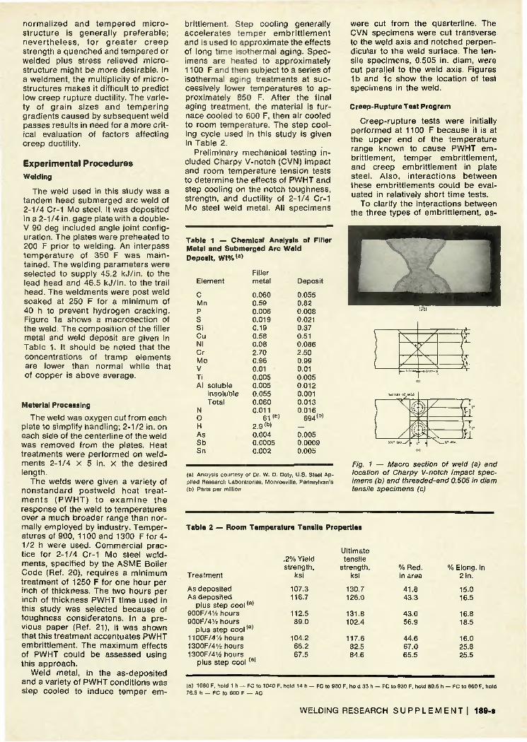
Fig. 2 — Rupture strength for 2-1/4 Cr-1 Mo steel weld metal at 1100 F
RUPTURE STRENGTH FOR STEP COOLED Wl I D
Fig. 4 — Creep rate for2-1/4 Cr-1 Mosteel weld metal at 1100 F
CREEP RATE FOR STEP COOLED WELD METAL
MINIMUM CHEEP R»TE. PCT/HR
TIME TO RUPTURE. HRS
Fig. 3 — Rupture strength for 2-1/4 Cr-1 Mo steel weld metal step cooled prior to testing at 1100 F
Fig. 5 — Creep rate for 2-1/4 Cr-1 Mo steel weld metal step cooled prior to testing at 1100 F
Table 5 — Creep Rupture Data for 2V* Cr-1 Mo Steel Weld Metal
Postweld Heat Treated at 900F
Creep-Rupture Data
Creep-rupture tests were initially performed at 1100 F but, for further clarification of interactions between creep embrittlement, temper embrittlement and PWHT embritt lement, subsequent tests were performed at 1150, 1200, and 1250 F. The creep and rupture data for all welds are listed in Tables 4-8. Figures 2-7 show the rupture, creep and ductility data for the 1100 F tests.
Rupture Life — Weld metal PWHT at or below 1100 F that has not been step cooled prior to creep has a rupture strength independent of initial strength level after approximately 20 h at 1100 F. The initial rapid decrease in rupture strength of as-deposited weld metal and weld metal PWHT at 900 F is the result of tempering during testing. When the rupture life exceeds approximately 20 h these two conditions have been tempered to a strength similar to that of the weld PWHT at 1100 F and thereafter the rupture strengths of all three conditions are comparable.
The rupture strength of the weld after a PWHT at 1300 F is lower than for the weld metal in the other three conditions. The four conditions are expected to have similar rupture strengths after 2000-5000 h of test-
Temp. F
1100
1150
1100
Stress, ksi
50 40 30 25 20
17.5
17.5 14
Time to rupture,
h
14.5 14.9 56.0
141.5 354.1 537.1
80.4 233.0
Creep rate, %/h
.0325
.0330
.0233
.0114
.00375
.00124
.0121
.00296
Postweld Heat Treated at 900 F, Then Step
30 22.5 20
17.5 15
89.2 277.6 391.4 651.7
1099.4
.0217
.0038
.00355
.00108
.000575
% Elong. in 2 in.
10.0 15.6 8.8 6.9 8.1 (a)
9.8 10.2
Cooled
8.7 8.0 (b) (b) 4.2
% Red. of area
27.4 30.8 13.4 15.8 6.6 (a)
14.8 14.8
14.5 17.7 5.1 8.9 8.9
(a) Specimen ruptured outside of gage length (b) Specimen ruptured on punch mark
ing of 1100 F. The long term exposure at 1100 F reduces the effect of prior heat treatment, thus reducing the rupture strength of all conditions to approximately the same level (Fig. 2).
A comparison of rupture strengths at 1150 F (Tables 4-8) shows that the strengths of the as-deposited and 900 F PWHT welds are similar. The rupture strengths of both are higher
than that of the weld PWHT at 1300 F. Step cooling has little effect on the
rupture strength for tests with a duration of at least 50 h (Fig. 3). After approximately 40 h at 1100 F, welds in both the base and step cooled conditions have been tempered to comparable strengths. The weld PWHT at 1300 F gives the best indication of the effect of step cooling on the rupture strength. Step cooling produces no
WELDING RESEARCH S U P P L E M E N T ! 191-8
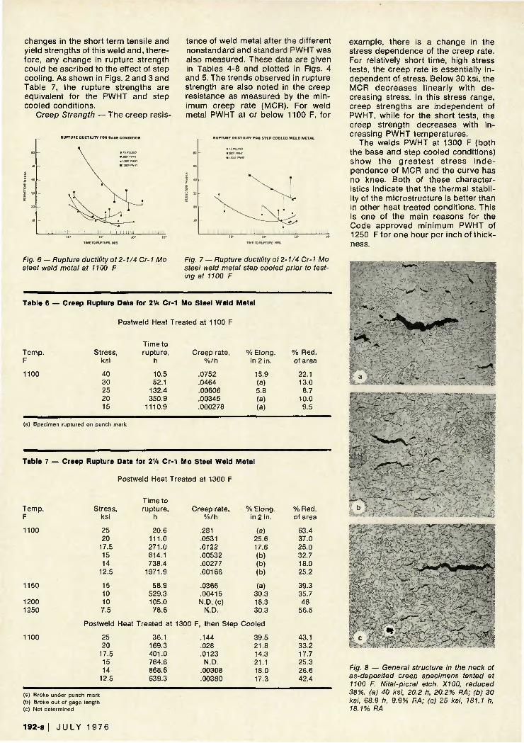
changes in the short term tensile and yield strengths of this weld and, therefore, any change in rupture strength could be ascribed to the effect of step cooling. As shown in Figs. 2 and 3 and Table 7, the rupture strengths are equivalent for the PWHT and step cooled conditions.
Creep Strength — The creep resis-
RUPTURE DUCTILITY FOR BASE CONDITION
tance of weld metal after the different nonstandard and standard PWHT was also measured. These data are given in Tables 4-8 and plotted in Figs. 4 and 5. The trends observed in rupture strength are also noted in the creep resistance as measured by the minimum creep rate (MCR). For weld metal PWHT at or below 1100 F, for
RUPTURE DUCTILITY FOR STEP COOLED WELD Is
I I *
20
TIME TO RUPTURE. HRS TIME TO RUPTURE. MRS
Fig. 6 — Rupture ductility of 2-1/4 Cr-1 Mo steel weld metal at 1100 F
Fig. 7 — Rupture ductility of 2-1/4 Cr-1 Mo steel weld metal step cooled prior to testing at 1100 F
Table 6 — Creep Rupture Data for 2'A Cr-1 Mo Steel Weld Metal
Postweld Heat Treated at 1100 F
Temp. F
1100
Stress, ksi
40 30 25 20 15
Time to rupture,
h
10.5 52.1
132.4 350.9
1110.9
Creep rate, %/h
.0752
.0464
.00606
.00345
.000278
% Elong. in 2 in.
15.9 (a) 5.8 (a) (a)
% Red. of area
22.1 13.0
8.7 10.0 9.5
(a) Specimen ruptured on punch mark
Table 7 — Creep Rupture Data for 2V« Cr-1 Mo Steel Weld Metal
Postweld Heat Treated at 1300 F
example, there is a change in the stress dependence of the creep rate. For relatively short time, high stress tests, the creep rate is essentially independent of stress. Below 30 ksi, the MCR decreases l inearly with decreasing stress. In this stress range, creep strengths are independent of PWHT, while for the short tests, the creep strength decreases with increasing PWHT temperatures.
The welds PWHT at 1300 F (both the base and step cooled conditions) show the greates t s t ress independence of MCR and the curve has no knee. Both of these characteristics indicate that the thermal stability of the microstructure is better than in other heat treated conditions. This is one of the main reasons for the Code approved minimum PWHT of 1250 F for one hour per inch of thickness.
Temp. F
1100
1150
1200 1250
1100
Stress, ksi
25 20
17.5 15 14
12.5
15 10 10 7.5
Time to rupture,
h
20.6 111.0 271.0 614.1 738.4
1971.9
58.9 529.3 105.0 78.6
Creep rate, %/h
.281
.0531
.0122
.00532
.00277
.00166
.0366
.00415 N.D. (c)
N.D.
% Elong. in 2 in.
(a) 25.6 17.6 (b) (b) (b)
(a) 30.3 18.3 30.3
Postweld Heat Treated at 1300 F, then Step Cooled
25 20
17.5 15 14
12.5
36.1 169.3 401.0 764.6 868.6 639.3
.144
.028
.0123 N.D.
.00308
.00380
39.5 21.8 14.3 21.1 18.0 17.3
% Red. of area
63.4 37.0 25.0 32.7 18.0 25.2
39.3 35.7 48
56.5
43.1 33.2 17.7 25.3 26.6 42.4
-^"V
(a) Broke under punch mark Ob) Broke out of gage length (c) Not determined
- i -SLL?"*--'
~v«€.
Fig. 8 — General structure in the neck of as-deposited creep specimens tested at 1100 F. Nital-picral etch. X100, reduced 38%. (a) 40 ksi, 20.2 h, 20.2% RA; (b) 30 ksi, 68.9 h, 9.9% RA; (c) 25 ksi, 181.1 h, 18.1% RA
192-s I J U L Y 1 9 7 6
Rupture Ductility: (a) Interaction of PWHT Embrittlement and Creep Embrittlement — A loss in rupture ductility with increasing time to rupture is common in creep. It has been attributed to a gradual change in fracture mode from transcrystalline shear to intergranular fracture (Refs. 1, 2, 6-9). Creep embr i t t lement can be in creased by grain boundary sliding, which causes increases in stress concentrations at triple points (Ref. 8), decohesion along the intergranular precipitate-matrix interfaces (Refs. 5, 11), and the formation of denuded zones adjacent to the grain boundaries (Refs. 1, 2, 12).
The % RA at rupture is plotted in Figs. 6 and 7. All welds except those PWHT at 900 F and 1100 F exhibit ductility minima as a function of time to rupture. The weld PWHT at 1300 F has the greatest overall ductility. The weld PWHT at 1100 F generally has the poorest ductility but the weld PWHT at 900 F and tested to rupture in 350 h has the lowest ductility of all tests. Prior step cooling generally improves % RA in long duration tests but the effect is not as pronounced as reported elsewhere (Ref. 22), probably because of the relatively high purity of this weld.
The microhardness of the creep specimens used for metallography was measured to evaluate the effects of creep strain on "cold working" of the weld and to examine possible correlations with the rupture ductility. The d i a m o n d py ram id ha rdness (DPH) values for a 50 g load are listed in Table 8. Also included for comparison are the DPH values for non-c r e e p t e s t e d we ld m e t a l . The hardness generally decreased with increasing time to rupture; however, no correlation was found between DPH and rupture ductility. The decreasing hardness indicates tempering. In addition, strain softening occurred during testing at 1100 F. For all creep specimens examined, the threaded end was harder than any portion of the gage section including the neck. In most specimens, the hardness of the neck 0.02 in. from the fracture was greater than the hardness of that part of the barrel that underwent macro-uniform deformation only. This may be the result of "cold work ing" during the final stages of fracture. The precise degree of "cold work" cannot be determined because some recovery may have occurred during cooling in the creep furnace after the specimen ruptured.
Metallography of creep specimens showed no evidence of "cold working" such as elongation of grains or intragranular porosity near the fracture. Optical micrographs of the neck of as-deposi ted creep specimens tested at 1100 F are shown in Fig. 8.
V1
M'r'i '" ' ' "
SW v d
I _ j
e f
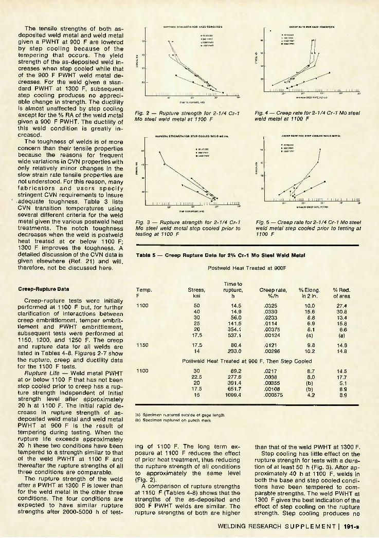
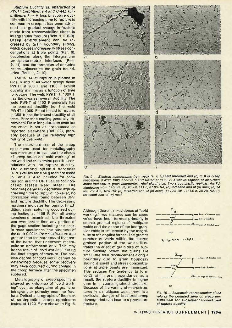
Fig. 9 — Electron micrographs from neck (a, c, e,) and threaded end (b, d, f) of creep specimens PWHT 1300 F/4-1/2 h and tested at 1100 F. A shows regions of disturbed metal adjacent to grain boundaries. Nttal-picral etch. Two stage plastic replicas. Au-Pd shadowed from fracture, (a) 20 ksi, 111 h, 37.8% RA: (b) threaded end of (a) neck; (c) 14 ksi, 738.4 h, 18% RA: (d) threaded end of (c) neck: (e) 12.5 ksi, 1971.9 h, 25.2% RA: (f) threaded end of (e) neck
Although there is no evidence of "cold working," two features can be seen: voids have been formed primarily in coarse grained regions of multipass welds and the shape of the intergranular voids is influenced by the magnitude of the applied stress. The greater number of voids within the coarse grained portion of the welds illustrates the effect of grain size on rupture ductility. When the grains are small, the total displacement along a boundary due to grain boundary sliding is small and stress concentrations at triple points are minimized. This reduces the tendency to form voids within grain boundaries; as a result, the rupture ductility is higher than in a coarse grained structure. Because of the variety of microstructures in a multipass weld, there is a particular danger of localized creep damage that can lead to a premature fracture.
tfge o f denuded zone
" I " y Gra in boundary
* Edge o f t - E d g e o f denuded zone
« ! * % •
T —— Edge o f denuded
U 1 W? e r a In boundary
1 Edge o f t
Fig. 10 — Schematic representation ot the role of the denuded zone on creep embrittlement and subsequent improvement of rupture ductility
WELDING RESEARCH S U P P L E M E N T ! 193-8

Table 8 — Diamond Pyramid Hardness for 21A Cr-1 Mo Steel Weld Metal Creep Specimens Tested to Rupture
Diamond pyramid hardness (50g)
Condition and test temp. F
As deposited 1100
1150
As deposited plus step cooled
1100
PWHT 900 F/4 h 1100
1150
PWHT 900 F/4</2 h, step cooled
1100
PWHT 1100 F/4V4 h 1100F
PWHT 1300 F/4% h 1100
1150
1200 1250 PWHT 1300 F/4V2 h
step cooled 11 OOF
(a) Not determined
Stress, ksi
40 30 25 20 15
40 17.5 15
40 20
17.5 17.5 14
22.5 20
17.5
25 20 15
20 14
12.5 15 10 10 7.5
20 17.5 15
Time to rupture,
h
20.2 68.9
181.1 95.9
226.9
6.3 604.0 148.7
14.9 354.1 537.1
80.4 233.0
277.6 391.4 651.7
132.4 350.9
1110.9
111.0 738.4
1971.9 58.9
529.3 105.0 78.6
169.3 401.0 764.6
% Red. in area
20.2 9.9
18.1 6.3
11.5
17.1 8.5
15.3
30.8 6.6
N.D. 14.8 14.8
17.7 5.1 8.9
8.7 10.0
9.5
37.0 18.0 25.2 39.3 35.7 48.0 56.5
33.2 17.7 25.3
Neck
— 218 211 206 177 159
— 146 159 155
225 176 183 173 167
— 187 169 173
— 188 191 191
— 186 173 160 149 169 162 179
— 175 166 159
Barrel
294 206 189 177 173 162
239 152 154 155 289 212 171 175 167 161
235 185 175 166 217 177 191 183 200 173 158 152 151 156 151 170
185 172 155 162
Thread end
— 229 206 211 N.D.<a)
N.D.
— N.D. N.D. N.D.
— 214 203 187 N.D. N.D.
— N.D. N.D. N.D.
— 197 199 183
— 177 177 174 N.D. N.D. N.D. N.D.
— N.D. N.D. N.D.
The shape of the creep voids changes with rupture life. When the applied stress is high (Fig. 8a), the creep voids are wide and have rounded corners. This suggests void formation in a region subjected to high stresses with the tensile stresses accelerating growth by pulling the voids apart. A void, or intergranular crack, is arrested when it meets an obstacle such as a triple point and the tip is blunted. On the other hand, when the applied stress is low, the intergranular voids form at a slower rate and tensile deformation is not as severe. The tips of the intergranular cracks are sharp and the cracks, or voids, are relatively narrow (Fig. 8c).
Electron micrographs of polished and etched creep specimens of the weld given a PWHT at 1300 F are shown in Fig. 9. The structures shown
are those from the neck (a, c, e) and threaded end (b, d, f). This series of specimens exhibited a ductility minimum in the curve of % RA as a function of t ime to rupture. In the neck, a denuded zone has formed adjacent to the grain boundar ies. Within this denuded zone plastic deformation occurred at the triple points (Fig. 9 a, c, e).
A denuded zone also exists in the threaded end and within the barrel of the three weld specimens in Fig. 9. In each specimen the width of the zone is larger in the neck than in the threaded end, suggesting that stress accelerates zone formation.
The initial loss in ductility and its subsequent improvement has been associated with the format ion of denuded zones (Refs. 5, 12, 13, 23), which in turn can be related to the
complex sequence of precipitation reactions that occur in 2-1/4 Cr-1 Mo steel. These react ions were f irst studied in wrought 2-1/4 Cr-1 Mo steel by Baker and Nutting (Ref. 24). The results published previously (Ref. 21) show that the same precipitation reactions occur in the weld metal during PWHT. Initially a fairly uniform disp e r s i o n of p r e c i p i t a t e s e x i s t s throughout the matrix. The stress-temperature conditions, coupled with the metallurgical instability of the carbides, cause a preferred prec ipitation within the grain boundaries. As the electron micrographs of the threaded ends of creep specimens show, denuded zones form without the aid of an applied stress.
A possible mechanism for the formation of the denuded zones is as follows. The elements in solid solution adjacent to the grain boundaries diffuse to the boundaries which are nucleation sites for precipitates. In an attempt to maintain solid solution equ i l i b r i um in the mat r i x , smal l precipitates adjacent to the grain boundaries dissolve. These new solid solution atoms diffuse to the boundaries and precipitate. The process continues, forming a zone depleted of precipitates next to the grain boundaries. When the denuded zones first form they are narrow, but widen with time.
Although denuded zone formation is not the primary factor affecting the rupture ductility in 2-1/4 Cr-1 Mo steel, it is a major contributor to the establishment of a ductility minimum with time to rupture. Creep strains are initially transferred across the grain boundary either by shear or classical grain boundary sliding. Rupture ductilities are high at short rupture life because the creep strain is distributed throughout the grains more or less uniformly. The fracture process is then typical tensile shear.
At lower stresses grain boundary sliding occurs. This causes a bui ld-up of stress concentrat ions at t r ip le points. This build-up is accentuated by a narrow denuded zone making it easier to initiate an intergranular crack. Since the shear strength of this zone is lower than that of either the matrix or grain boundary, most of the deformation occurs within this zone. The relative motion of grains sliding past each other by non-ideal grain boundary sl id ing causes a rapid build-up of stress at triple points. A low ductility grain boundary fracture, therefore, can occur.
As the time to rupture increases, the denuded zone gets wider. A greater displacement across the zone can be accommodated before a critical shear strain is reached and since the wide denuded zone can sus-
194-s I J U L Y 1 9 7 6
tain appreciable plastic deformation, s t r e s s r e l a x a t i o n c a n o c c u r . Therefore, the rate of build-up of stress at triple points is lowered and rupture ductility increases.
The effect of the width of the denuded zone on creep rupture ductility is shown schematically in Fig. 10. Since 7 = D/W, for a given value of the shear strain 7, the displacement that can be accommodated across the denuded zone is directly proportional to its width. Thus, in comparing Fig. 10a with Fig. 10b, when 71 = 72, D,/W, = D2/W2. When the denuded zone is narrow, Fig. 10a, a small D can produce a strain that exceeds the yield strain, causing either plastic deformation or rupture. The increase in stress concentration at triple points is rapid if plastic deformation occurs. This causes crack propagation along grain boundaries and low ductility. When the zone is wide, Fig. 10b, the build-up of stresses at triple points is much slower. The wide denuded zones can undergo greater stress relaxation during creep and rupture ductility increases.
Rupture Ductility: (b) Interaction of Temper Embrittlement and Creep Embrittlement — The primary factor in the loss of creep ductility in 2-1/4 Cr-1 Mo welds is probably impurity elements such as As, Sb, P, and Sn. Bruscato (Ref. 22) and Tipler (Ref. 18) have shown a close correlation between purity and rupture ductility. This probably results from an increase of decohesion between the matrix and intergranular precipitates caused by the location of these elements at these interfaces.
During creep of weld metal, intergranular voids form by a combination of grain boundary sliding and vacancy diffusion to the boundaries. It has been proposed by Wingrove and Taplin (Ref. 25) that the voids are stabilized by the diffusion of gas or alloying elements to the grain boundaries lowering the surface energy of the voids.
Another explanation for void formation in creep is an extension of the mechanism of temper embritt lement proposed by Rellick and McMahon (Ref. 26). When intergranular precipitates form, impurity elements are rejected from the matrix volume into which the precipitates are growing. There is a build up of impurities on the interface because of their low diffusion rates. This reduces the cohesive strength of the interface. When grain boundary sliding occurs producing shear stresses across the denuded zone sufficient to break the precipitate/matrix interfacial bonds, a stable intergranular void is formed.
To evaluate this hypothesis, void surfaces are examined fractograph-
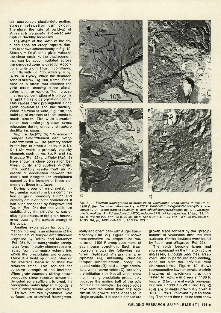
Fig. 11. — Electron fractographs of creep voids. Specimens creep tested to rupture at 1100 F, then fractured below neck at -320 F. Replicated intergranular precipitates are shown by "A,"creep induced voids by "B"and void initiating precipitates by "C." Two stage plastic replicas. Au-Pd shadowed. X3200, reduced 17%. (a) As-deposited. 25 ksi, 181.1 h, 18.1% RA: (b) 900 F/4-1/2 h, 30 ksi, 56 h, 13.4% RA: (c) 1100 F/4-1-2 h, 20 ksi, 350.9 h, 10.0% RA: (d) 1300 F/4-1/2 h, 17.5 ksi, 271 h
ically and chemically with Auger spectroscopy (Ref. 27). Figure 11 shows representative low temperature fractures of 1100 F creep specimens of each base cond i t ion . Each frac-tograph shows the fo l lowing features: replicated intergranular precipitates (A), indicating classical temper embr i t t lement ; creep in duced voids (B); and a large precipitate within some voids (C), probably the initiation site. Not all voids show the initiating precipitate presumably because the mating half of the void contains the particle. The creep voids have features within them that look similar to growth steps observed in single crystals. It is possible these are
growth steps formed by the "precipitation" of vacancies onto the void surfaces. Similar features were found by Taplin and Wingrove (Ref. 25).
The voids become larger and more equiaxed as the time to rupture increases, although prior heat treatment, and in particular step cooling, does not alter the individual void character ist ics. Figure 12 shows representative low temperature brittle fractures of specimens previously tested to rupture in creep at 1100 F. Figure 12 (a-c) are of welds previously given a 1300 F PWHT and Fig. 12 (d-f) are of welds previously given a 1300 F PWHT followed by step cooling. The short time rupture tests show
WELDING RESEARCH S U P P L E M E N T ! 195-8
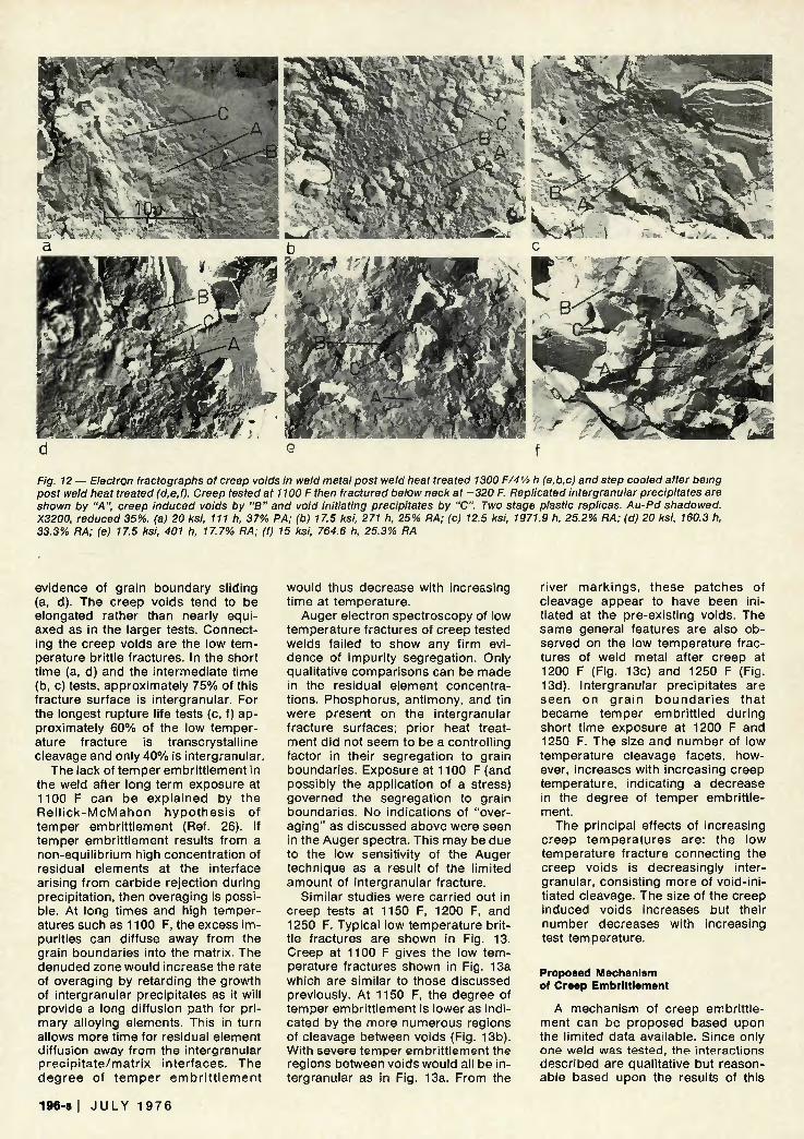
Fig. 12 — Electron fractographs of creep voids in weld metal post weld heat treated 1300 F/4V* h (a.b.c) and step cooled after being post weld heat treated (d,e,f). Creep tested at 1100 F then fractured below neck at -320 F. Replicated intergranular precipitates are shown by "A", creep induced voids by "B" and void initiating precipitates by "C". Two stage plastic replicas. Au-Pd shadowed. X3200, reduced 35%. (a) 20 ksi, 111 h, 37% RA; (b) 17.5 ksi, 271 h, 25% RA; (c) 12.5 ksi, 1971.9 h, 25.2% RA; (d) 20 ksi, 160.3 h, 33.3% RA; (e) 17.5 ksi, 401 h, 17.7% RA; (f) 15 ksi, 764.6 h, 25.3% RA
evidence of grain boundary sliding (a, d). The creep voids tend to be elongated rather than nearly equiaxed as in the larger tests. Connecting the creep voids are the low temperature brittle fractures. In the short t ime (a, d) and the intermediate time (b, c) tests, approximately 75% of this fracture surface is intergranular. For the longest rupture life tests (c, f) approximately 60% of the low temperature fracture is transcrystalline cleavage and only 40% is intergranular.
The lack of temper embritt lement in the weld after long term exposure at 1100 F can be explained by the R e l l i c k - M c M a h o n hypothes is of temper embritt lement (Ref. 26). If temper embritt lement results from a non-equil ibrium high concentration of residual elements at the interface arising from carbide rejection during precipitation, then overaging is possible. At long times and high temperatures such as 1100 F, the excess impurities can diffuse away from the grain boundaries into the matrix. The denuded zone would increase the rate of overaging by retarding the growth of intergranular precipitates as it will provide a long diffusion path for pr imary alloying elements. This in turn allows more time for residual element diffusion away from the intergranular prec ip i ta te/matr ix interfaces. The degree of t emper embr i t t l emen t
would thus decrease with increasing time at temperature.
Auger electron spectroscopy of low temperature fractures of creep tested welds failed to show any firm evidence of impurity segregation. Only qualitative comparisons can be made in the residual element concentrations. Phosphorus, antimony, and tin were present on the intergranular fracture surfaces; prior heat treatment did not seem to be a controlling factor in their segregation to grain boundaries. Exposure at 1100 F (and possibly the application of a stress) governed the segregation to grain boundaries. No indications of "overaging" as discussed above were seen in the Auger spectra. This may be due to the low sensitivity of the Auger technique as a result of the limited amount of intergranular fracture.
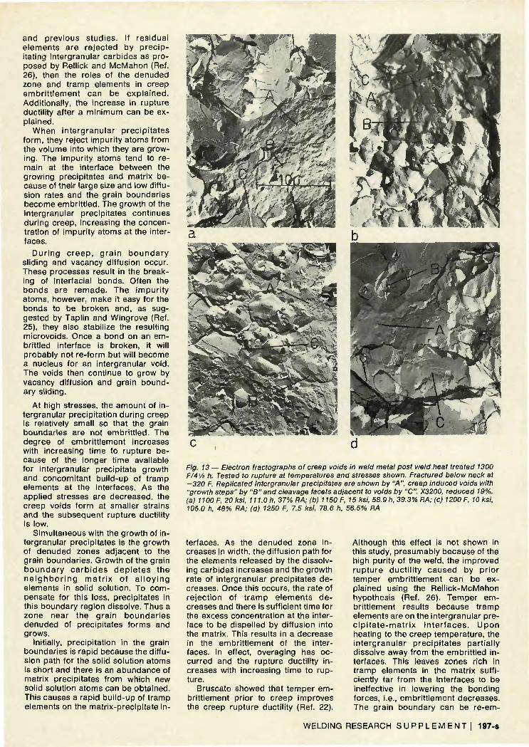
Similar studies were carried out in creep tests at 1150 F, 1200 F, and 1250 F. Typical low temperature brittle fractures are shown in Fig. 13. Creep at 1100 F gives the low temperature fractures shown in Fig. 13a which are similar to those discussed previously. At 1150 F, the degree of temper embritt lement is lower as indicated by the more numerous regions of cleavage between voids (Fig. 13b). With severe temper embritt lement the regions between voids would all be intergranular as in Fig. 13a. From the
river mark ings, these patches of cleavage appear to have been initiated at the pre-existing voids. The same general features are also observed on the low temperature fractures of weld metal after creep at 1200 F (Fig. 13c) and 1250 F (Fig. 13d). Intergranular precipitates are seen on gra in bounda r i es that became temper embritt led during short time exposure at 1200 F and 1250 F. The size and number of low temperature cleavage facets, however, increases with increasing creep temperature, indicating a decrease in the degree of temper embritt lement.
The principal effects of increasing creep temperatures are; the low temperature fracture connecting the creep voids is decreasingly intergranular, consisting more of void-initiated cleavage. The size of the creep induced voids increases but their number decreases with increasing test temperature.
Proposed Mechanism of Creep Embrittlement
A mechanism of creep embritt lement can be proposed based upon the limited data available. Since only one weld was tested, the interactions described are qualitative but reasonable based upon the results of this
196-8 | J U L Y 1 9 7 6
and previous studies. If residual elements are rejected by prec ipitating intergranular carbides as proposed by Rellick and McMahon (Ref. 26), then the roles of the denuded zone and tramp elements in creep embr i t t lement can be expla ined. Additionally, the increase in rupture ductility after a minimum can be explained.
When intergranular precipi tates form, they reject impurity atoms from the volume into which they are growing. The impurity atoms tend to remain at the interface between the growing precipitates and matrix because of their large size and low diffusion rates and the grain boundaries become embritt led. The growth of the intergranular precipitates continues during creep, increasing the concentration of impurity atoms at the interfaces.
Dur ing c reep , g ra in boundary sliding and vacancy diffusion occur. These processes result in the breaking of interfacial bonds. Often the bonds are remade. The impuri ty atoms, however, make it easy for the bonds to be broken and, as suggested by Taplin and Wingrove (Ref. 25), they also stabilize the resulting microvoids. Once a bond on an embrittled interface is broken, it will probably not re-form but will become a nucleus for an intergranular void. The voids then continue to grow by vacancy diffusion and grain boundary sliding.
At high stresses, the amount of intergranular precipitation during creep is relatively small so that the grain boundaries are not embritt led. The degree of embritt lement increases with increasing time to rupture because of the longer time available for intergranular precipitate growth and concomitant build-up of tramp elements at the interfaces. As the applied stresses are decreased, the creep voids form at smaller strains and the subsequent rupture ductility is low.
Simultaneous with the growth of intergranular precipitates is the growth of denuded zones adjacent to the grain boundaries. Growth of the grain boundary ca rb ides dep le tes the n e i g h b o r i n g m a t r i x of a l l o y i n g elements in solid solution. To compensate for this loss, precipitates in this boundary region dissolve. Thus a zone near the grain boundar ies denuded of precipitates forms and grows.
Initially, precipitation in the grain boundaries is rapid because the diffusion path for the solid solution atoms is short and there is an abundance of matrix precipitates from which new solid solution atoms can be obtained. This causes a rapid build-up of tramp elements on the matrix-precipitate in-
Fig. 13 — Electron fractographs of creep voids in weld metal post weld heat treated 1300 F/4V2 h. Tested to rupture at temperatures and stresses shown. Fractured below neck at -320 F. Replicated intergranular precipitates are shown by "A", creep induced voids with "growth steps" by "B" and cleavage facets adjacent to voids by "C". X3200, reduced 19%. (a) 1100 F, 20 ksi, 111.0 h, 37% RA; (b) 1150 F, 15 ksi, 58.9 h, 39.3% RA; (c) 1200 F, 10 ksi, 105.0 h, 48% RA; (d) 1250 F, 7.5 ksi, 78.6 h, 56.5% RA
terfaces. As the denuded zone increases in width, the diffusion path for the elements released by the dissolving carbides increases and the growth rate of intergranular precipitates decreases. Once this occurs, the rate of reject ion of t ramp elements de creases and there is sufficient time for the excess concentration at the interface to be dispelled by diffusion into the matrix. This results in a decrease in the embritt lement of the interfaces. In effect, overaging has occurred and the rupture ductility increases with increasing time to rupture.
Bruscato showed that temper embrittlement prior to creep improves the creep rupture ductility (Ref. 22).
Although this effect is not shown in this study, presumably because of the high purity of the weld, the improved rupture ducti l i ty caused by pr ior temper embritt lement can be explained using the Rell ick-McMahon hypothesis (Ref. 26). Temper embrittlement results because tramp elements are on the intergranular prec ip i t a te -ma t r i x in te r faces . Upon heating to the creep temperature, the intergranular precipi tates partially dissolve away from the embritt led interfaces. This leaves zones rich in tramp elements in the matrix sufficiently far f rom the interfaces to be ineffective in lowering the bonding forces, i.e., embritt lement decreases. The grain boundary can be re-em-
WELDING RESEARCH S U P P L E M E N T ! 197-8
brittled only by the formation of new precipitate particles which, in turn, requi res the reject ion of addi t ional tramp elements from the grain boundary regions. For there to be sufficient time for this to occur, the applied stress must be low. Generally, the stress is low enough that creep strain is gradual, void formation is minimal, and overaging can occur. The net result is a higher rupture ductility than if no temper embritt lement occurred before creep.
Creep rupture ductility is reduced by PWHT embritt lement by precipitat ion hardening. This is explained primarily by the fact that the matrix is strengthened by coherent precipitates (Ref. 21). The matrix cannot withstand large creep strains so that it is necessary for the grain boundaries to accommodate these strains. Void formation is accelerated because of the high strains and stabilization by the segregated tramp elements. As a result of both processes, void growth continues and low ductility fractures occur.
Conclusions
The study of creep embrit t lement in 2-1/4 Cr-1 Mo steel weld metal has shown that heat treatment prior to creep has a greater effect on ductility than on rupture or creep strength. If the creep temperature is high enough to cause temper ing , the rupture resistance and creep strength will be characteristic of the creep temperature. Prior heat t reatment only affects weld metal strength when the temperature of creep is significantly below that of the prior heat treatment so that tempering does not occur during creep.
The rupture strength and creep s t reng th were shown to be i n fluenced by pre-creep heat treatment for short rupture lives. Because the majority of the tests were at 1100 F, the effects of heat treatments at temperatures below 1100 F were generally eliminated for rupture lives exceeding 20 h. The effects of prior heat treatment were eliminated in shorter times at 1150 F.
Creep embritt lement, as defined herein, has been found to occur at 1100 F in this weld regardless of prior heat treatment. Several important conc lus ions about the p h e n o m enology and mechanism of creep embrittlement can be made based upon this work:
a. Rupture ductility decreases with inc reas ing t ime to rup tu re reaching a minimum; beyond the minimum the ductility increases with increasing rupture life.
b. Postweld heat treating within the temperature range known to
cause PWHT embritt lement by precipitation hardening (900 F to a p p r o x i m a t e l y 1150 F) results in poor creep ductility at 1100 F.
c. Postweld heat treating at 900 F results in the most severe creep embritt lement as measured by lowest observed rupture ductility.
d . P o s t w e l d heat t r e a t i n g at 1300 F gives the best rupture ductility under all test conditions.
The mechanism of creep embritt lement is related to the generation of intergranular voids. This is controlled by the formation of a denuded zone and the segregation of residual elements to the intergranular precipi t a t e / m a t r i x i n t e r f a c e s . M e t a l lography and fractography substantiate the non-equil ibrium theory of temper embritt lement and an extension of this theory to the phenomenon of creep embritt lement and the interaction of creep and temper embrittlement.
Acknowledgments The authors wish to express appre
ciation to the Pressure Vessel Research Committee for the financial support for the program. Also, the assistance of Lukens Steel Company to one of the authors (R.A.S.) is also acknowledged.
References 1. Glen, John, The Problem of the
Creep of Metals, Murex Welding Processes, Ltd., London, England, Chapter XV, 1968.
2. Swift, R. A., "Creep Rupture Tests on 2-1/4 Cr-1 Mo Simulated Heat Affected Zone," Lukens Steel Company RDR 69-11, June 1969.
3. Ferrell, Donald E. and Pense, A. W., 'Creep Embrittlement of 2-1/4% Cr-1% Mo Steel." Report to Materials Division, Pressure Vessel Research Council, May 1973.
4. Gulya, J. A., "Creep Tests on 2-1/4% Cr-1% Mo Steel," Lukens Steel Company, RDR 68-14, June 1968.
5. Garofalo, F„ Fundamentals of Creep and Creep Rupture in Metals, MacMillan Company, New York, New York, p. 223, 1965.
6. Garofalo, F„ Ibid., p. 221, 1965. 7. McLean, D., Mechanical Properties
of Metals. John Wiley and Sons, Inc., New York, New York, p. 307, 1962.
8. Mullendore, A. W. and Grant, N. J., "Grain Boundary Behavior in High Temperature Deformation," Deformation and Fracture at Elevated Temperatures, N. J. Grant, A. W. Mullendore Eds., The M.I.T. Press, Cambridge, Mass. 1965.
9. Pickering, F. B., "Some Aspects of Creep Strength and Ductility in Steels. II," Iron and Steel. 148-152, April 1968.
10. Beevers, C. J., "Elevated Temperature Failure Process." High Temperature Material: The Controlling Physical Process, A. J. Kennedy. Ed.. Oliver and
Boyd, London, England, 1968. 11. Pickering, F. B., "Some Aspects of
Creep Strength and Ductility in Steels, III," Iron and Steel, 206-209, May 1968.
12. Roper, C. R., Jr., "Further Metallographic Information on the Causes of Creep Embrittlement in 2-1/4 Cr-1 Mo Steel," Lukens Steel Company RDR 69-2, January 1969.
13. Swift, R. A., "The Mechanism of Creep Embrittlement in 2-1/4 Cr-1 Mo Steel." 2-1/4 Chrome-1 Molybdenum Steel in Pressure Vessels and Piping, ASME, New York, New York, 1971.
14. Carpenter, O. R. and Emmanuel, G. N., "The Use of Quenched and Tempered 2-1/4 Cr-1 Mo Steel for Fabrication of Advanced Design Pressure Vessels," Symposium of Heat Treated Steels for Elevated Temperature Service, ASME, New York, New York, 1966.
15. Emmanuel, G. N. and Leyda, W. E., "Longtime High Temperature Properties of Cr-Mo Weld Metal," Properties ot Weldments at Elevated Temperature, ASME, New York, New York, 1968.
16. Lister, E., Mickleraith, J., and Higgenbottom, A., "High Temperature Properties of Steampipe Welds," High Temperature Properties of Steels, ISI Publication 97, 1966.
17. Mandich, L. I., Fogleman, E. L., and Gulya, J. A., "Elevated Temperature Properties of Heavy Gauge Cr-Mo Steel Plates," Symposium on Heat Treated Steels for Elevated Temperature Service, ASME, New York, New York, 1966.
18. Tipler, H. R., "The Role of Trace Elements in Creep Embrittlement and Cavitation of Cr-Mo-V Steels," National Physical Laboratory Report, Teddington, England, 1972.
19. Bruscato, Robert, "Temper Embrittlement and Creep Embrittlement of 2V« Cr-1 Mo Shielded Metal Arc Weld Deposits", Welding Journal, 49 (4), April 1970, Research Suppl. 148-s to 156-s, 1970.
20. ASME Pressure Vessel and Boiler Code, Part VIM, ASME, New York, New York, UNC56, 1971.
21. Swift, R. A.. Rogers, H. C, "Embrittlement of 2-1/4 Cr-1 Mo Steel Weld Metal by Postweld Heat Treatment," Welding Journal, 52 (4), April 1973, Research Suppl., 145-s to 153-s.
22. Bruscato, Robert, "High Temperature Embrittlement Phenomena of 2'A Cr-1 Mo Weldments," ASME Pub. 71-Pet-19, ASME, New York, New York, 1971.
23. Roper, C. R., Jr., "An Investigation of the Causes of Creep Embrittlement in A387-D Steel," Lukens Steel Company RDR 68-12. June 1968.
24. Baker, R. G. and Nutting, J., "The Tempering of 2-1/4% Cr-1% Mo Steel After Quenching and Normalizing," Jl. Iron and Steel Inst. (London), 192, 257-268, 1959.
25. Taplin, D. M. R. and Wingrove, A. L., "Study of Intergranular Cavitation in Iron by Electron Microscopy of Fracture Surfaces," Acta Met. 15, 1231-1236, 1967.
26. Rellick, J. R., McMahon, C. J., Jr., "Intergranular Embrittlement of Iron-Carbon Alloys by Impurities Rejected During Carbide Precipitation," Met. Trans. 5 (11), 1974, 2439-2450.
27. Stein. D. F., Private Communication. Analyses courtesy of Michigan Technological University. Department of Metallurgy.
198-s I J U L Y 1 9 7 6
The new edition of the Structural Welding Code, AWS Dl.1-75 is here — completely revised with important requirements that you need to know.
Automatic Revision Service The price of both the looseleaf and the soft-cover
bound versions of the 1975 Structural Welding Code includes the 1976 and 1977 Revisions, automatically sent to you as they are published.
Sturdy 3-Ring Binder The heavy-duty vinyl binder will hold the Structural
Welding Code, the soon-to-be published Code Commentary, and the Reinforcing Steel Welding Code, AWS D12.1-75 (the latter two documents to be sold separately). The binder includes dividers for the main sections of Dl.1-75 as well as the other two publications mentioned.
A limited number of soft cover bound copies is available.
Structural Welding Code 1. Looseleaf text, Dl.1-75, in binder with dividers plus
1976 and 1977 revisions $25.00 2. Soft cover bound text, Dl.1-75, plus 1976 and 1977 revisions $24.00
Reinforcing Steel Welding Code, AWS D12.1.75 soft-cover, bound $5.00 Code Commentary, soft-cover bound Price not set
Discounts: 25 percent to A and B members; 20 percent to bookstores, public libraries and schools; 15 percent to C and D members. Add 4 percent sales tax in Florida. Send orders to: American Welding Society, 2501 N.W. 7th St., Miami, FL 33125.
WELDING RESEARCH S U P P L E M E N T ! 199-8