Structure of grain boundaries in wet, synthetic … of grain boundaries in wet, synthetic...
12
Structure of grain boundaries in wet, synthetic polycrystalline, statically recrystallizing halite – evidence from cryo-SEM observations O. SCHENK 1 , J. L. URAI 1 AND S. PIAZOLO 2, * 1 Geologie – Endogene Dynamik, RWTH Aachen University, Germany; 2 Department of Earth Science, Liverpool University, Liverpool, UK ABSTRACT It is well known from nature and experiments that the presence of brine strongly affects the microstructural evo- lution and the mechanical and transport properties of halite. Existing interpretations of the grain boundary struc- ture in deformed, wet, salt samples annealed statically at room temperature are based on indirect evidence from reflected light microscopy and conventional scanning electron microscopy. This paper presents direct observations of fluid-filled grain boundaries using the cryogenic-scanning electron microscope (cryo-SEM) in which the grain boundary fluids were frozen before breaking the samples. The rapid cooling transforms the brine into two phases, i.e. ice and hydrohalite, which are easily recognized from characteristic segregation patterns. We studied samples of wet, synthetic, polycrystalline halite annealed under static conditions at room temperature. In coarse-grained samples, fine-scale segregation patterns were observed at the boundaries of the primary recrystallizing grains. These points indicate the existence of fluid films with a thickness in the range of 30 nm, but the finer scale struc- ture of the fluid remains unknown. In fine-grained samples, the distribution and reorganization of fluids with annealing time is recorded by the combination of contact healing and successive accumulation of fluids in triple junction tubes. The contact healing is attributed to the small initial grain size, such that the fluid film necks down by accumulating the fluids into previously existing triple junctions via neck growth. Electron backscatter diffraction measurements of both primary and secondary recrystallized grains indicate that they are euhedral, i.e. the grain growth morphology is controlled by the anisotropy of the grain boundary energy of the growing grain, which results in planar growth faces. Key words: cryo-SEM, fluids, grain boundary, halite, morphology, recrystallization. Received 7 December 2004; accepted 16 September 2005 Corresponding author: Oliver Schenk, Geologie-Endogene Dynamik, RWTH Aachen University, Lochnerstr. 4-20, 52056 Aachen, Germany E-mail: [email protected]. Tel.: +49 241 80 95416. Fax: +49 241 80 92358. Geofluids (2006) 6, 93–104 INTRODUCTION The presence of fluids has major effects on the dynamics of geological processes in the Earth’s mantle and crust (e.g. Fyfe et al. 1978). In minerals, such as quartz (Gri- ggs 1974; Hirth & Tullis 1992; Jaoul et al. 1984; Kro- nenberg & Tullis 1984; Post & Tullis 1998; Tullis & Yund 1982), feldspar (Dimanov et al. 1999; Tullis et al. 1996), olivine (Mei & Kohlstedt 2000a,b), bischofite (Urai 1983), carnallite (Urai 1985) and halite (e.g. Spiers et al. 1990; Urai et al. 1986a), water-rich fluids play a significant role in recrystallization, grain growth and development of texture (Evans et al. 2001; Urai et al. 1986a). Halite has been investigated in detail because the inter- play of fluid morphology and deformation can be studied at relatively low temperatures and pressures (e.g. Urai et al. 1986b), allowing systematic laboratory experiments of practical duration (Watanabe & Peach 2002). The results are also relevant to other fluid-bearing minerals, including partially molten rocks (Spiers et al. 1988). *Present address: Department of Geology and Geochemistry, Stockholm University, 10691 Stockholm, Sweden. Geofluids (2006) 6, 93–104 Ó 2006 The Authors, Journal compilation Ó 2006 Blackwell Publishing Ltd
Transcript of Structure of grain boundaries in wet, synthetic … of grain boundaries in wet, synthetic...

Structure of grain boundaries in wet, syntheticpolycrystalline, statically recrystallizing halite – evidencefrom cryo-SEM observations
O. SCHENK1, J . L. URAI1 AND S. PIAZOLO2 ,*1Geologie – Endogene Dynamik, RWTH Aachen University, Germany; 2Department of Earth Science, Liverpool University,
Liverpool, UK
ABSTRACT
It is well known from nature and experiments that the presence of brine strongly affects the microstructural evo-
lution and the mechanical and transport properties of halite. Existing interpretations of the grain boundary struc-
ture in deformed, wet, salt samples annealed statically at room temperature are based on indirect evidence from
reflected light microscopy and conventional scanning electron microscopy. This paper presents direct observations
of fluid-filled grain boundaries using the cryogenic-scanning electron microscope (cryo-SEM) in which the grain
boundary fluids were frozen before breaking the samples. The rapid cooling transforms the brine into two phases,
i.e. ice and hydrohalite, which are easily recognized from characteristic segregation patterns. We studied samples
of wet, synthetic, polycrystalline halite annealed under static conditions at room temperature. In coarse-grained
samples, fine-scale segregation patterns were observed at the boundaries of the primary recrystallizing grains.
These points indicate the existence of fluid films with a thickness in the range of 30 nm, but the finer scale struc-
ture of the fluid remains unknown. In fine-grained samples, the distribution and reorganization of fluids with
annealing time is recorded by the combination of contact healing and successive accumulation of fluids in triple
junction tubes. The contact healing is attributed to the small initial grain size, such that the fluid film necks down
by accumulating the fluids into previously existing triple junctions via neck growth. Electron backscatter diffraction
measurements of both primary and secondary recrystallized grains indicate that they are euhedral, i.e. the grain
growth morphology is controlled by the anisotropy of the grain boundary energy of the growing grain, which
results in planar growth faces.
Key words: cryo-SEM, fluids, grain boundary, halite, morphology, recrystallization.
Received 7 December 2004; accepted 16 September 2005
Corresponding author: Oliver Schenk, Geologie-Endogene Dynamik, RWTH Aachen University, Lochnerstr. 4-20,
52056 Aachen, Germany
E-mail: [email protected]. Tel.: +49 241 80 95416. Fax: +49 241 80 92358.
Geofluids (2006) 6, 93–104
INTRODUCTION
The presence of fluids has major effects on the dynamics
of geological processes in the Earth’s mantle and crust
(e.g. Fyfe et al. 1978). In minerals, such as quartz (Gri-
ggs 1974; Hirth & Tullis 1992; Jaoul et al. 1984; Kro-
nenberg & Tullis 1984; Post & Tullis 1998; Tullis &
Yund 1982), feldspar (Dimanov et al. 1999; Tullis et al.
1996), olivine (Mei & Kohlstedt 2000a,b), bischofite
(Urai 1983), carnallite (Urai 1985) and halite (e.g.
Spiers et al. 1990; Urai et al. 1986a), water-rich fluids
play a significant role in recrystallization, grain growth
and development of texture (Evans et al. 2001; Urai
et al. 1986a).
Halite has been investigated in detail because the inter-
play of fluid morphology and deformation can be studied
at relatively low temperatures and pressures (e.g. Urai et al.
1986b), allowing systematic laboratory experiments of
practical duration (Watanabe & Peach 2002). The results
are also relevant to other fluid-bearing minerals, including
partially molten rocks (Spiers et al. 1988).*Present address: Department of Geology and Geochemistry,
Stockholm University, 10691 Stockholm, Sweden.
Geofluids (2006) 6, 93–104
� 2006 The Authors, Journal compilation � 2006 Blackwell Publishing Ltd

The effect of fluids on grain boundary mass transfer in
halite has been demonstrated by numerous examples from
nature, and also by experiments during both fluid-phase
diffusional creep (pressure solution) (de Meer et al. 2002;
Hickman & Evans 1991; Martin et al. 1999; Peach 1991;
Schutjens 1991; Spiers & Schutjens 1990; Spiers et al.
1990) and fluid-assisted grain boundary migration (Peach
et al. 2001; Schenk & Urai 2004; Urai et al. 1986b;
Watanabe & Peach 2002). However, the structure of the
halite grain boundaries that contain water is still a matter
of debate. Firstly, for pressure solution, three different,
nonexclusive models have been proposed (den Brok et al.
2002): (i) the thin film model, (ii) the island-channel
model and (iii) the island-crack model.
In the thin film boundary model (Hickman & Evans
1991; Renard & Ortoleva 1997; Rutter 1976) the grains
are separated by a thin, structured water film with a thick-
ness of a few nanometres. This film is proposed to transmit
the contact stress, and dissolution followed by diffusion is
the process of transport of material. The island-channel
boundary model (Lehner 1990; Spiers & Schutjens 1990)
is based on the assumption that, during pressure solution,
the fluids residing in thin films are squeezed out between
the grains, resulting in solid–solid contact (islands)
through which the contact stresses are transmitted,
together with water-filled channels through which the
material transport takes place by diffusion. This microscop-
ically rough island-channel structure is dynamically stable.
The island-crack boundary model (den Brok 1998; Dysthe
et al. 2003; Gratz 1991) proposes static islands that are
separated by microfracture-controlled fluid channels. In
contrast to the solid–solid contact of the island-channel
model, the islands in this model contain thin films compar-
able to the earlier proposed thin film boundary model.
However, compared to the thin film model, the total diffu-
sivity in the island-crack model is increased by the presence
of the microcracks.
Secondly, experiments on wet polycrystalline halite
deformed at temperatures between room temperature and
150�C in the nondilatant field indicate that halite recrystal-
lizes readily both during and after deformation (Drury &
Urai 1990; Peach et al. 2001; Spiers et al. 1990; Urai
et al. 1986a,b; Watanabe & Peach 2002). The grain
boundaries are interpreted to contain thin fluid films. A
method to show the presence of such brine films in halite
samples is the application of the ether test (Spiers et al.
1986): cooling during evaporation of the ether disrupts
the fluid film into isolated droplets. Urai et al. (1986b)
demonstrated the presence of fluid films from scanning
electron microscope (SEM) observations on deformed,
water-bearing halite samples: 1 month after cessation of
deformation grain boundaries were smooth, whereas sam-
ples annealed for 1 year contained grain boundaries with
isolated cavities marking former fluid inclusions. The
authors interpreted these results as evidence of grain
boundary brine films that shrink into isolated fluid inclu-
sions after grain boundary migration stops. Similar obser-
vations were shown by in situ experiments conducted on
wet bischofite, where water-filled grain boundaries neck
down after cessation of grain boundary migration (Urai
1987).
The fluid-filled grain boundaries are interpreted to
migrate by (i) dissolution of the deformed grains, (ii) diffu-
sion through the brine film and (iii) precipitation on the
low-index facets of the recrystallized grains forming
smooth grain surfaces (e.g. Spiers et al. 1990; Urai et al.
1986a), comparable to the step model of Gleiter (1969).
However, so far the nature of such fluid films in migrating
boundaries has been inferred only indirectly.
A significant problem is that the observations were
made after removal of the stress, and this could have led
to a redistribution of the fluid by viscous flow of brine
(Hickman & Evans 1991; Peach et al. 2001; Watanabe
& Peach 2002). This problem was avoided in a recent
study in which the microstructural evolution of wet,
compacted, statically recrystallizing halite samples with
different initial grain sizes was presented (Schenk & Urai
2004). The microstructural evolution in Schenk & Urai
(2004) is briefly summarized in Fig. 1: in the coarse-
grained samples, primary recrystallization resulted in the
nucleation and growth of euhedral grains, which replaced
the original, deformed grains (Fig. 1A). Inside the fine-
grained samples, primary recrystallization was followed by
normal grain growth, but stopped after a few hours
because of contact healing (Fig. 1B). Exaggerated grain
growth (secondary recrystallization) is initiated at this
stage (Fig. 1C).
Schenk & Urai (2004) interpreted the growth of the
euhedral primary and secondary recrystallized grains to be
due to the presence of brine films on the grain boundaries,
as dry grain boundaries only migrate at temperatures above
approximately 400�C (Franssen 1993; Guillope & Poirier
1979). However, the details of the fluid distribution and
its influence on grain boundary migration were only partly
resolved, because fluid was removed during sample pre-
paration.
In this paper, we therefore set out to investigate directly,
and in detail, the nature of the fluid in grain boundaries
during different stages of recrystallization within com-
pacted, polycrystalline halite samples. To do this we stu-
died samples using the cryo-SEM. Small rock chips are
shock-frozen to a very low temperature (approximately
)190�C) and can be used for chemical characterizations
(Samson & Walker, 2000; Timofeeff et al. 2001) and for
visualization of the distribution of fluids in rocks, in partic-
ular to investigate qualitatively fluid–mineral interfaces
(Durand & Rosenberg 1998; Mann et al. 1994; Monma
et al. 1997). In order to characterize the crystallographic
94 O. SCHENK et al.
� 2006 The Authors, Journal compilation � 2006 Blackwell Publishing Ltd, Geofluids, 6, 93–104

orientations of grain boundaries we used electron backscat-
ter diffraction (EBSD) analysis.
METHODS
Experimental methods
Preparation of compacted samples.
The sample preparation technique was that used by Schenk
& Urai (2004). Here we summarize the procedure briefly.
Wet sodium chloride powder of analytical grade (Roth,
Art. 9265.3; NaCl content >99.9%) of two different grain
size classes (<10 and 200–355 lm) was compacted (cold-
pressed, T ¼ approximately 25�C) uniaxially with a pres-
sure of 150 MPa for 5 min. The resulting aggregates have
connected brine-filled porosities of less than 2%, together
with volumetrically very minor, localized occurrences of
air-filled pores. The samples were annealed at room tem-
perature (24 ± 1�C) over periods of up to 9 months in
small, air-tight containers with small amounts of saturated
salt solution. This solution was not in contact with the
samples, ensuring that the vapour pressure of H2O around
the samples was buffered at the equilibrium value. Only
samples 139 and 141 were stored in a wet salt mush (see
Table 1 for a detailed description of the compacted sam-
ples).
Analytical methods
Preparation for cryo-SEM observations.
For direct observation of the brine-filled grain boundary
sections of synthetic halite samples, we used a field emis-
sion scanning electron microscope (FESEM JSM-6300F,
JEOL) equipped with a dedicated cryo-preparation cham-
ber (CT 1500 HF, Oxford Instruments) at the Depart-
ment of Plant Cell Biology, Wageningen University, The
Netherlands. Where necessary, the samples were ground to
the required thickness of approximately 1.6 mm very care-
fully to minimize any damage, at a temperature of approxi-
mately 25�C. The sample was then placed into the slot of
the cryo-SEM holder and fixed with carbon conductive
cement (Leit-C, Neubauer chemicals). It was secured addi-
tionally by tightening carefully the screw of the holder.
Subsequently, the whole assembly (sample with holder)
was immersed in liquid nitrogen ()196�C). Once frozen,
the whole unit was transferred into the cryo-preparation
chamber at a temperature of )90�C and a pressure of
1.3 · 10)3 Pa (high vacuum conditions), in which the
sample was fractured using a cold knife ()196�C) at ade-
quate distance from the tightened holder (see sketch in
Fig. 2A). After approximately 5 min (sublimation stage),
the sample was sputter coated with 8 nm platinum and
subsequently transferred into the SEM on the sample
Fig. 1. Schematic illustration of the microstruc-
tural evolution of wet compacted, statically
recrystallizing halite samples. The processes and
grain size evolution of the samples described in
the present paper are identical to that described
in Schenk & Urai (2004). Note that normal grain
growth is inhibited, whereas growth of primary
recrystallized and exaggerated grains continue.
Table 1. Overview of samples described in this
paper. Sample Type of salt Starting grain size (lm) Annealing time (days) Observations
1-XXs Brine: Roth – 0.50 Segregation pattern
085a Roth 200–355 252.23 Primary recrystallization
111a Roth <10 180.97 Normal grain growth
138a Roth <10 29.93 Exaggerated grain growth
139* Roth <10 6.70 Normal grain growth
141* Roth <10 1.10 Normal grain growth
146 Roth 200–355 139.98 Primary recrystallization
152 Roth 200–355 0.50 Primary recrystallization
*Stored in salt mush.
Structure of wet grain boundaries in halite 95
� 2006 The Authors, Journal compilation � 2006 Blackwell Publishing Ltd, Geofluids, , 93–104

holder, at a temperature between )170 and )190�C. Ima-
ges were recorded digitally.
Bicrystal ‘calibration’ tests.
To interpret the frozen structure of brine inside the com-
pacted samples, we compared them with the structure of a
thin film of frozen, saturated sodium chloride solution
between halite plates. For this an industrially grown halite
single crystal was cleaved along {100} cleavage facets into
two thin wafers, which were bonded with a droplet of sat-
urated sodium chloride solution (Roth, Art. 9265.3; NaCl
content >99.9%) for 12 h, relying on capillary action to
avoid applying any external stress. Subsequently, this
assembly was inserted into a cryo-SEM holder and frozen
at a temperature of )90�C for 5 min, before it was frac-
tured inside the cryo-preparation chamber.
EBSD.
Detailed EBSD analysis was conducted on selected samples
to investigate the nature of grain boundaries of primary
and secondary recrystallized grains in the annealed samples.
To obtain a high-resolution EBSD pattern, the samples
(thick, compacted, unfrozen sections) were mechanically
polished using 1200-, 2400- and 4000-grade carborundum
paper, removing dust at regular intervals with a blast of dry
compressed air. To remove surface damage, the samples
were chemically polished in pure analytical grade methanol
for 10 sec, and then immediately and vigorously rinsed in
a jet of diethyl ether. Finally, samples were carbon coated
to reduce charging during EBSD analysis.
Samples were analysed in a field-emission gun (FEG)
CamScan X500 SEM at the University of Liverpool. Full
crystallographic orientation data were obtained from EBSD
patterns using a 20 kV acceleration voltage and a beam
current of 7 nA. EBSD patterns were auto-indexed using
the CHANNEL 5.03 software of HKL Technology. The cen-
tre of five to six Kikuchi bands was detected automatically,
whereby the solid angles calculated from the patterns were
compared with the calculated halite patterns originating
from 47 reflectors. Data were obtained by moving the
beam at a fixed step size of 2 lm. The average percentage
of EBSD patterns that could not be indexed ranged
between 30% and 35%; most of the unindexed analyses
were at high-angle grain boundaries. The maps were proc-
essed to remove erroneous data in order to provide a more
complete reconstruction of the microstructure (Prior et al.
2002). The accuracy of individual EBSD orientation meas-
urements is better than 1�. The misorientation angle
between grains was calculated by selecting the minimum
misorientation angle and its corresponding axis from all
possible symmetric variants (cf. Wheeler et al. 2001). We
present data obtained in a combination of displays: (i)
maps showing the spatial distribution of grains and their
crystallography in different grey scales and (ii) three-
dimensional representation of the crystallographic orienta-
tion of individual grains of special interest.
Observations
The microstructural evolution of the samples is identical
to that observed by Schenk & Urai (2004). Both the
Fig. 2. Cryo-SEM micrographs of the single crystal – brine setup: (A) two
thin wafers of halite single crystals (XX-1 and XX-2) were attached to each
other parallel to the {100} facets with a droplet of saturated brine and bro-
ken with a cold knife inside the cryo-chamber; (B and C) details of the seg-
regation pattern of the frozen brine film with the two phases, hydrohalite
and ice, the latter as negative imprint because of evaporation during subli-
mation.
96 O. SCHENK et al.
� 2006 The Authors, Journal compilation � 2006 Blackwell Publishing Ltd, Geofluids, 6, 93–104

fine- and coarse-grained samples are characterized by a
porosity connected through triple junction tubes (to pre-
vent confusion we use the terms triple junction and triple
junction tubes solely in a geometric sense, without relat-
ing them to textural equilibrium as those conditions were
not attained in our experiments). In the present study,
grain boundary morphology during recrystallization was
studied on broken surfaces of samples annealed for differ-
ent periods using the cryo-FESEM. An overview of the
samples described in this paper and the main observations
are given in Table 1.
Segregation patterns of frozen brine
Setup with halite single crystals and brine.
In order to correctly identify the earlier presence of brine
at grain boundaries, we ‘calibrated’ our observations
against the segregation pattern on faces of a sample in
which brine was enclosed between the cleavage faces of
two single crystal wafers of halite (Fig. 2A). Because of the
rapid cooling, the saturated brine shock-freezes and is
transformed into the two phases, i.e. ice and hydrohalite
(NaCl · 2H2O) (Bodnar 1993; Roedder 1984). During
the sublimation period at the sample stage (5 min at
)90�C), the ice crystals evaporate leaving behind voids in a
hydrohalite foam (Fig. 2B,C) (we call the resultant texture
a ‘segregation pattern’). Accordingly, if such pores and
‘foam’ are observed in our samples, we suggest that they
are indicative of the earlier presence of brine.
General comparison of segregation patterns observed
in experimental samples.
Brine inclusions are common in halite, as illustrated in a
coarse-grained sample inside an original, deformed grain
(Fig. 3). This frozen fluid inclusion shows the characteristic
segregation pattern described above, indicating that it rep-
resents frozen salt solution, i.e. with the two phases hydro-
halite and (evaporated) ice. Inside both the coarse- and
fine-grained samples, similar patterns were observed in
pores, triple junction tubes and on grain boundaries, dem-
onstrating that they are also brine in a frozen state. Thus,
these patterns provide direct evidence for the distribution
of brine inside the compacted samples.
The volume increase of approximately 15% that is associ-
ated with the transformation of saturated brine into the
two phases hydrohalite and ice might result in misinterpre-
tations of the microstructure as the previously brine-filled
grain boundaries or triple junctions expand. However,
Fig. 3B shows that the shock-freezing did not result in
fracturing of the surrounding grain. Furthermore, this
photomicrograph illustrates that the size of the pores left
by the evaporated ice is five times smaller than that in the
single crystal brine setup (Fig. 2). As the cooling rate was
the same for all samples, it is suggested that the dimen-
sions of the segregated components are related to the vol-
ume of the fluid.
Observations on coarse-grained samples during primary
recrystallization
Inside the coarse-grained aggregates (initial grain size:
200–355 lm), primary recrystallization dominated textural
evolution. Nucleation of primary recrystallized grains
occurred in high-strain zones close to the contact regions
of original, deformed grains. These new grains are charac-
terized by a cubic shape, and replace the surrounding
deformed material. This microstructural evolution is docu-
mented by the three samples that were annealed for
0.5 days, 4.5 months and 8.5 months (samples 152, 146
and 085a, respectively; see Table 1). Segregation patterns
of the frozen fluids indicate that brine was present in all
samples. If three or more recrystallized grains (i.e. strain-
free grains smaller than approximately 20 lm) are in con-
tact, the frozen brine is only present in triple junctions
(however not in the sense of textural equilibrium) (Fig. 4).
Fig. 3. Cryo-SEM micrographs of a coarse, deformed grain in sample 152
with a frozen fluid inclusion. The segregation pattern is similar to that of
the saturated brine in the setup shown in Fig. 2. See Table 1 for a detailed
description of the sample (also relevant to all sample micrographs shown in
this paper).
Structure of wet grain boundaries in halite 97
� 2006 The Authors, Journal compilation � 2006 Blackwell Publishing Ltd, Geofluids, , 93–104

Grain boundary migration occurs if a strain-free grain is
in contact with a deformed grain. Inside sample 146
(annealed for 4.5 months), some of these grains are larger
than 100 lm (Fig. 5). This contact zone between the new
grain (recrystallized) and the old grain (deformed) is char-
acterized by a very thin segregation pattern indicating a
fluid film with a thickness of less than 30 nm (Fig. 5C).
Additionally, tiny pores visible on the lower crystal face of
the deformed crystals suggest that they are related to fro-
zen fluids (see arrow in Fig. 5C). This is supported by the
fact that no air-filled pores were observed inside new
grains. Backscatter analysis indicates that there are no
measurable differences in chemistry between the original
deformed grain, the recrystallized grain and the solid phase
of the segregation pattern (cf. Heard & Ryerson 1986),
suggesting that second phases other than brine did not
influence this contact region. Inside the same sample, a dif-
ferent but rare situation is displayed (Fig. 6). Here, the
porosity is predominantly air-filled, as shown by the lack of
segregation pattern. However, remnants of a frozen fluid
phase are observed at the contact zone between a recrystal-
lized grain and a deformed grain. The thickness of this
fluid film is approximately 200 nm (Fig. 6B,C) with a seg-
regation pattern similar to that shown in the grain bound-
ary region of Fig. 5C.
Observations on fine-grained samples during primary
recrystallization, normal grain growth and exaggerated
grain growth
Microstructural evolution of the fine-grained samples (ini-
tial grain size <10 lm) starts with primary recrystallization,
followed by a reduction of irregularities in grain boundary
morphology and rearrangement of porosity. These proces-
ses occur only in the first hours (see Schenk & Urai 2004).
There is no sign of significant normal grain growth; how-
ever, at this stage exaggerated grain growth begins in some
samples.
Fluids are present in all the fine-grained samples, whe-
ther they were stored in brine saturated environment or
salt mush, regardless of the annealing time ranging from
1 day to 6 months (samples 141, 139, 138a and 111a)
(see Table 1 for the detailed sample description). During
Fig. 4. Cryo-SEM micrographs of sample 152. At the contact of the two
original, deformed coarse grains new, recrystallized, cube-shaped grains
start to grow. Segregation pattern in a triple junction points to the presence
of fluids.
Fig. 5. Cryo-SEM micrographs of sample 146 showing thin segregation
pattern between the primary recrystallized and the deformed grain. This
pattern [arrow in (C)] is interpreted to represent a frozen fluid film with a
thickness of less than 30 nm. Note that the deformed grain is characterized
by a complex cleavage pattern when compared to the defect-free grain.
98 O. SCHENK et al.
� 2006 The Authors, Journal compilation � 2006 Blackwell Publishing Ltd, Geofluids, 6, 93–104
the first few days, fluids – indicated by the characteristic
segregation pattern – reside on all irregular and on some
curved grain boundaries, forming films with a thickness of
less than 150 nm, but predominantly they are present in
triple junctions or in pores that developed by impingement
of the growing grains (Fig. 7) (see also Elliot et al. 1997).
After 1 week of annealing at room temperature the
microstructure is characterized by solid–solid contacts
(Fig. 8; see solid arrow). The pores remain irregular
Fig. 6. Cryo-SEM micrographs of sample 146 showing a primary recrystal-
lizing grain growing into an old, deformed grain. The arrow in (C) points to
the remnants of a frozen fluid film at the contact region. Note that this is a
rare region in which porosity is predominantly air-filled.
Fig. 7. Cryo-SEM micrographs of sample 141 showing that fluids are pre-
sent in triple junctions and in grain boundaries in the early stages of anneal-
ing. Close to large pores the grains grow normal to the {100} facets;
however, at grain–grain contacts the grain boundaries are irregular and
curved. The details in (B) are interpreted to represent the first step of con-
tact healing (arrow).
Fig. 8. Cryo-SEM micrograph of sample 139 with the typical segregation
pattern of brine-filled porosity. The fine-sized grains grow with low-index
facets into the fluid-filled pore (dashed arrow). Note the high diversity of
apparent dihedral angles. The solid arrow points to an immobile solid–solid
contact region of two recrystallized grains.
Structure of wet grain boundaries in halite 99
� 2006 The Authors, Journal compilation � 2006 Blackwell Publishing Ltd, Geofluids, , 93–104

because of the lattice-dependent (euhedral) growth of the
crystals into the porosity (Fig. 8; see dashed arrow) with
apparent dihedral angles varying over a broad range
because of impingement of the growing grains. An isolated
brine-filled inclusion (250 · 50 nm) (Fig. 9) is interpreted
to represent an inclusion left behind from a migrating
fluid-filled grain boundary. However, this might also be
explained by the presence of a fluid-filled pore resting on
the grain boundary. The microstructure of sample 111a
(annealed for 6 months) is characterized by predominantly
straight or smoothly curved grain boundaries without
interactions of fluids and an interconnected porosity with
fluids present only along triple junctions (Fig. 10).
Exaggerated grain growth is common inside these fine-
grained samples as shown by reflected light microscopy
and SEM (see EBSD pattern of sample 138a; annealed for
1 month; Fig. 11). However, cryo-SEM did not allow
detailed observations on the contact of exaggerated grains
with the fine-grained matrix, probably because of the
plucking-out of the large grains during the low-tempera-
ture preparation.
Crystallographic nature of grain boundaries of primary
and secondary recrystallized grains
After an annealing period of 8 months in a brine-saturated,
humid environment, the coarse-grained sample 085a (ini-
tial grain size 200–355 lm) contained several large, euhe-
dral grains. They show little to no lattice distortion within
any individual grain, and a dominance of boundaries
Fig. 9. Cryo-SEM micrograph of sample 139. Some grain boundaries are
fluid-filled, irregular and curved, whereas others are already healed. The
arrow points to fluid inclusion that was probably left behind during grain
boundary migration.
Fig. 10. Cryo-SEM micrograph of sample 111a showing that after months
of annealing the microstructure is reorganized with commonly straight,
fluid-free grain boundaries (dashed arrow) and fluids still present in triple
junctions (solid arrow).
Fig. 11. SEM and EBSD micrographs of fine-grained sample 138a indica-
ting that exaggerated grown grains are in fact euhedral, i.e. its growth is
lattice-dependent. (A) Band contrast analysis showing exaggerated grains
several orders of magnitude larger than the matrix grains. The fine-grained
matrix appears dark because of the abundance of grain boundaries, which
appear dark in a band contrast analysis image. Note the insets representing
the crystallographic nature of the individual exaggerated grains. These
show that the boundaries of the exaggerated grains are {100} facets. (B)
Same area as shown in (A) but showing grains in different grey shades.
100 O. SCHENK et al.
� 2006 The Authors, Journal compilation � 2006 Blackwell Publishing Ltd, Geofluids, 6, 93–104
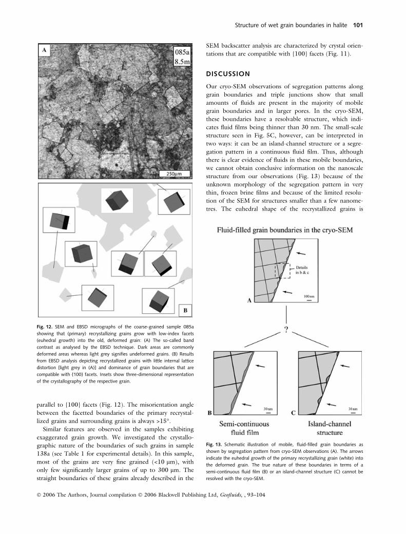
parallel to {100} facets (Fig. 12). The misorientation angle
between the facetted boundaries of the primary recrystal-
lized grains and surrounding grains is always >15�.Similar features are observed in the samples exhibiting
exaggerated grain growth. We investigated the crystallo-
graphic nature of the boundaries of such grains in sample
138a (see Table 1 for experimental details). In this sample,
most of the grains are very fine grained (<10 lm), with
only few significantly larger grains of up to 300 lm. The
straight boundaries of these grains already described in the
SEM backscatter analysis are characterized by crystal orien-
tations that are compatible with {100} facets (Fig. 11).
DISCUSSION
Our cryo-SEM observations of segregation patterns along
grain boundaries and triple junctions show that small
amounts of fluids are present in the majority of mobile
grain boundaries and in larger pores. In the cryo-SEM,
these boundaries have a resolvable structure, which indi-
cates fluid films being thinner than 30 nm. The small-scale
structure seen in Fig. 5C, however, can be interpreted in
two ways: it can be an island-channel structure or a segre-
gation pattern in a continuous fluid film. Thus, although
there is clear evidence of fluids in these mobile boundaries,
we cannot obtain conclusive information on the nanoscale
structure from our observations (Fig. 13) because of the
unknown morphology of the segregation pattern in very
thin, frozen brine films and because of the limited resolu-
tion of the SEM for structures smaller than a few nanome-
tres. The euhedral shape of the recrystallized grains is
Fig. 12. SEM and EBSD micrographs of the coarse-grained sample 085a
showing that (primary) recrystallizing grains grow with low-index facets
(euhedral growth) into the old, deformed grain: (A) The so-called band
contrast as analysed by the EBSD technique. Dark areas are commonly
deformed areas whereas light grey signifies undeformed grains. (B) Results
from EBSD analysis depicting recrystallized grains with little internal lattice
distortion [light grey in (A)] and dominance of grain boundaries that are
compatible with {100} facets. Insets show three-dimensional representation
of the crystallography of the respective grain.
Fig. 13. Schematic illustration of mobile, fluid-filled grain boundaries as
shown by segregation pattern from cryo-SEM observations (A). The arrows
indicate the euhedral growth of the primary recrystallizing grain (white) into
the deformed grain. The true nature of these boundaries in terms of a
semi-continuous fluid film (B) or an island-channel structure (C) cannot be
resolved with the cryo-SEM.
Structure of wet grain boundaries in halite 101
� 2006 The Authors, Journal compilation � 2006 Blackwell Publishing Ltd, Geofluids, , 93–104

related to such fluid-filled grain boundaries (Fig. 5C). The
surface of the recrystallized grain is inferred to be an F-
facet. However, the nature of the fluid-filled grain bound-
ary, i.e. whether it is a semi-continuous fluid film
(Fig. 13B) or has an island-channel structure (Fig. 13C),
remains unclear.
The presence of fluids in grain boundaries agrees with
previous observations on mobile grain boundaries in wet
halite (Drury & Urai 1990; Peach et al. 2001; Schenk &
Urai 2004; Urai et al. 1986a,b; Watanabe & Peach 2002),
whereas experiments on dry sodium chloride show that the
grain boundaries are immobile below temperatures of
400�C (Franssen 1993; Guillope & Poirier 1979). The fact
that recrystallized grains are characterized by an euhedral
shape with a clear crystallographic relationship in terms of
facets (Figs 5, 11 and 12) is in agreement with observa-
tions of similar microstructures in other fluid-bearing,
recrystallizing materials (e.g. Kingery 1974; Skrotzki &
Welch 1983).
Such a preferred growth of primary or secondary recrys-
tallized grains is interpreted to be either (i) a result of the
high surface energy anisotropy of the wetted NaCl grain
boundaries, (ii) a growth mechanism similar to that seen in
crystal-melt systems where a ledge mechanism leads to the
euhedral shape according to the step model of Gleiter
(1969) or (iii) a combination of (i) and (ii). High surface
energy anisotropies are expected to play a major role in
fully wetted grain boundaries. Observations in olivine–
ultramafic melt systems showed that completely wetted
grain boundaries are often found parallel to low-index fac-
ets [(010), (110) and (021)] (Jung & Waff 1998). These
are similar to our observations of growing primary recrys-
tallizing and exaggerated grains normal to the {100} faces.
Walte et al. (2003) have questioned the importance of
surface energy anisotropy. They showed that completely
wetted grain boundaries can simply form by consumption
of small grains during fluid-enhanced static recrystalliza-
tion, and concluded that there is no need to relate the
structures to surface energy anisotropy, even though this
might enhance the effect.
Another possible explanation for the euhedral shape of
the primary and secondary recrystallized grains is the ledge
jump grain boundary migration mechanism described by
Gleiter (1969). The assumption of a fluid-filled grain
boundary with two solid–fluid interfaces and a fluid layer
in between is similar in terms of the sharp transition of
crystal lattice and adjacent grain boundary and the influ-
ence of the orientation of the crystal on the migration rate.
According to the step model, the motion of the grain
boundary in the presence of a driving force proceeds by (i)
dissolution of ions from favoured sites (steps) of the
shrinking old grain and from deformation-related disloca-
tions that reach the surface, (ii) diffusion through the fluid
layer and (iii) re-attachment at preferential steps of the
growing strain-free grain. The euhedral shape suggests that
diffusion is not restricted to the shortest distance. How-
ever, the fluid layer regulates (balances) the transport of
ions, such that they are precipitated at favoured steps to
preserve the character of the {100} facet.
Inside the coarse-grained samples, grain boundary
migration stops if two or more recrystallized grains come
into contact because of the reduction in driving force as
the grains have the same (low) dislocation density. Only
the grain boundary (surface) energy can drive further grain
boundary migration. In this situation, the grain boundary
fluid is accumulated along triple junctions leaving behind
healed, brine-free grain boundaries. These immobile solid–
solid contacts could have developed by boundary anneal-
ing, i.e. the surface energy driven attraction of grain
boundary fluids into the triple junction network, a process
that is controlled by the contact angle.
The cessation of normal grain growth inside the fine-
grained samples is also interpreted to be caused by such
boundary healing: below a critical grain size the fluid-filled
grain boundary contracts and accumulates in the triple
junction network because of the effect of surface energy
forces (Visser 1999).
CONCLUSIONS
Cryo-SEM observations offer direct evidence of fluid-filled
grain boundaries in statically recrystallizing wet, polycrys-
talline sodium chloride samples. The frozen fluid phase is
represented by the segregation pattern composed of the
two phases, hydrohalite and evaporated ice.
The thickness of such migrating brine-filled grain
boundaries is usually less than 30 nm. Finer scale structure
is obscured by resolution of SEM and segregation of brine
during freezing.
Primary recrystallized growing and exaggerated-grown
grains exhibit euhedral shapes with {100} facets. We
interpret this type of growth as a consequence of either
significant anisotropic grain boundary energy and/or a
solid-melt/brine type growth mechanism with a ledge
jump mechanism.
The results are in agreement with a model of brine-filled
grain boundaries during primary recrystallization and exag-
gerated grain growth, and healed grain boundaries in nor-
mal grain growth.
ACKNOWLEDGEMENTS
We are grateful to A. van der Aelst (Department of Plant
Cell Biology of Wageningen University, The Netherlands)
for his valuable assistance with the cryo-FESEM. The com-
ments on the phase conditions of the NaCl–H2O system at
low temperature by R. Bodnar are greatly appreciated.
H. Siemes is thanked for providing the NaCl single crys-
102 O. SCHENK et al.
� 2006 The Authors, Journal compilation � 2006 Blackwell Publishing Ltd, Geofluids, 6, 93–104

tals. M. Holness and C.J. Spiers are thanked for their thor-
ough and constructive reviews that improved the manu-
script. This project is funded by the Deutsche
Forschungsgemeinschaft (UR 64/4-1). S.P. acknowledges
financial support by Marie Curie Fellowship HPMF-CT-
2001-01457, NERC grant NER/A/S/2001/01181 and
HEFCE through the grant JR98LIPR.
REFERENCES
Bodnar RJ (1993) Revised equation and table for determining the
freezing point depression of H2O–NaCl solutions. Geochimica etCosmochimica Acta, 57, 683–4.
de Meer S, Spiers CJ, Peach CJ, Watanabe T (2002) Diffusive
properties of fluid-filled grain boundaries measured electrically
during active pressure solution. Earth and Planetary Science Let-ters, 200, 147–57.
den Brok SWJ (1998) Effect of microcracking on pressure-solution
strain rate; the Gratz grain-boundary model. Geology, 26, 915–8.
den Brok B, Morel J, Zahid, M (2002) In situ experimentalstudy of roughness development at a stressed solid/fluid inter-
face. In: Deformation Mechanisms, Rheology and Tectonics;Current Status and Future Perspectives (eds de Meer S, Drury
MR, de Bresser JHP, Pennock GM), pp. 73–83. GeologicalSociety Special Publications 200. Geological Society of London,
London.
Dimanov A, Dresen G, Xiao X, Wirth R (1999) Grain boundary
diffusion creep of synthetic anorthite aggregates: the effect ofwater. Journal of Geophysical Research, 104, 10483–97.
Drury MR, Urai JL (1990) Deformation-related recrystallization
processes. Tectonophysics, 172, 235–53.Durand C, Rosenberg E (1998) Fluid distribution in kaolinite- or
illite-bearing cores: cryo-SEM observations versus bulk measure-
ments. Journal of Petroleum Science and Engineering, 19, 65–72.
Dysthe DK, Renard F, Feder J, Jamtveit B, Meakin P, Jøssang T(2003) High resolution measurements of pressure solution
creep. Physical Review E, 68, 1–13.
Elliot MT, Cheadle MJ, Jerram DA (1997) On the identification
of textural equilibrium in rocks using dihedral angle measure-ments. Geology, 25, 355–8.
Evans B, Renner J, Hirth G (2001) A few remarks on the kinetics
of static grain growth in rocks. International Journal of EarthScience (Geologische Rundschau), 90, 88–103.
Franssen RCMW (1993) Rheology of synthetic rocksalt with
emphasis on the influence of deformation history and geometry
on the flow behaviour. PhD Thesis, Universiteit Utrecht.Fyfe WS, Price NJ, Thompson AB (1978) Fluids in the Earth’s
Crust. Elsevier, Amsterdam.
Gleiter H (1969) The mechanism of grain boundary migration.
Acta Metallurgica, 17, 565–73.Gratz AJ (1991) Solution-transfer compaction of quartzites; pro-
gress toward a rate law. Geology, 19, 901–4.
Griggs D (1974) A model of hydrolytic weakening in quartz. Jour-nal of Geophysical Research, 79, 1653–61.
Guillope M, Poirier JP (1979) Dynamic recrystallization during
creep of single-crystalline halite: an experimental study. Journalof Geophysical Research, 84, 5557–67.
Heard HC, Ryerson FJ (1986) Effect of cation impurities on
steady-state flow of salt. In: Mineral and Rock Deformation;Laboratory Studies; the Paterson Volume (eds Hobbs BE, Heard
HC). AGU Geophysical Monograph, vol. 36, pp. 99–115.American Geophysical Union, Washington, DC.
Hickman SH, Evans B (1991) Experimental pressure solution inhalite; the effect of grain/interphase boundary structure. Journalof the Geological Society, 148, 549–60.
Hirth G, Tullis J (1992) Dislocation creep regimes in quartz
aggregates. Journal of Structural Geology, 14, 145–59.Jaoul O, Tullis J, Kronenberg A (1984) The effect of varying
water contents on the creep behavior of heavitree quartzite.
Journal of Geophysical Research, 89, 4298–312.Jung H, Waff HS (1998) Olivine crystallographic control and
anisotropic melt distribution in ultramafic partial melts. Geophysi-cal Research Letters, 25, 2901–4.
Kingery WD (1974) Plausible concepts necessary and sufficient forinterpretation of ceramic grain boundary phenomena: II, solute
segregation, grain boundary diffusion, and general discussion.
Journal of the American Ceramic Society, 57, 74–83.
Kronenberg AK, Tullis J (1984) Flow strengths of quartz aggre-gates: grain size and pressure effects due to hydrolytic weaken-
ing. Journal of Geophysical Research, 89, 4281–97.
Lehner FK (1990) Thermodynamics of rock deformation by pres-sure solution. In: Deformation Processes in Minerals, Ceramicsand Rocks (eds Barber DJ, Meredith PD), pp. 296–333. Unwin
Hyman, Boston, MA.
Mann U, Neisel JD, Burchard WG, Heinen V, Welte DH (1994)Fluid–rock interfaces as revealed by cryo-scanning electron micr-
oscopy. First Break, 12, 131–36.
Martin B, Roeller K, Stoeckhert B (1999) Low-stress pressure
solution experiments on halite single-crystals. Tectonophysics,308, 299–310.
Mei S, Kohlstedt DL (2000a) Influence of water on plastic defor-
mation of olivine aggregates 1. Diffusion creep regime. Journalof Geophysical Research, B, Solid Earth and Planets, 105,
21457–69.
Mei S, Kohlstedt DL (2000b) Influence of water on plastic defor-
mation of olivine aggregates 2. Dislocation creep regime. Jour-nal of Geophysical Research, B, Solid Earth and Planets, 105,
21471–81.
Monma T, Kudo M, Masuko T (1997) Flow behaviors of smec-
tite/water suspensions in terms of particle-coagulated structures.Nendo Kagaku, 37, 47–57.
Peach CJ (1991) Influence of deformation on the fluid transport
properties of salt rocks. PhD Thesis, Universiteit Utrecht.
Peach CJ, Spiers CJ, Trimby PW (2001) Effect of confining pres-sure on dilatation, recrystallization, and flow of rock salt at
150�C. Journal of Geophysical Research, 106, 13315–28.
Post A, Tullis J (1998) The rate of water penetration in experi-mentally deformed quartzite: implications for hydrolytic weaken-
ing. Tectonophysics, 295, 117–37.
Prior DJ, Wheeler J, Peruzzo L, Spiess R, Storey C (2002) Some
garnet microstructures: an illustration of the potential of orien-tation maps and misorientation analysis in microstructural stud-
ies. Journal of Structural Geology, 24, 999–1011.
Renard F, Ortoleva P (1997) Water films at grain-grain contacts:
Debye–Huckel, osmotic model of stress, salinity, and mineralogydependence. Geochimica et Cosmochimica Acta, 61, 1963–70.
Roedder E (1984) The fluids in salt. American Mineralogist, 69,
413–39.Rutter EH (1976) The kinetics of rock deformation by pressure
solution. Philosophical Transactions of the Royal Society of LondonA, 283, 203–19.
Samson IM, Walker RT (2000) Cryogenic Raman spectroscopicstudies in the system NaCl–CaCl2–H2O and implications for
low-temperature phase behavior in aqueous fluid inclusions.
Canadian Mineralogist, 38, 35–43.
Structure of wet grain boundaries in halite 103
� 2006 The Authors, Journal compilation � 2006 Blackwell Publishing Ltd, Geofluids, , 93–104

Schenk O, Urai JL (2004) Microstructural evolution and grainboundary structure during static recrystallization in synthetic
polycrystals of sodium chloride containing saturated brine. Con-tributions to Mineralogy and Petrology, 146, 671–82.
Schutjens P (1991) Intergranular pressure solution in halite aggre-gates and quartz sands: an experimental investigation. PhD The-
sis, Universiteit Utrecht.
Skrotzki W, Welch P (1983) Development of texture and micro-structure in extruded ionic polycrystalline aggregates. Tectono-physics, 99, 47–61.
Spiers CJ, Schutjens P (1990) Densification of crystalline aggre-
gates by fluid-phase diffusional creep. In: Deformation Processesin Minerals, Ceramics and Rocks (eds Barber DJ, Meredith PD),
pp. 334–353, Unwin Hyman, Boston, MA.
Spiers CJ, Urai J, Lister GS, Boland JN, Zwart HJ (1986) Theinfluence of fluid-rock interaction on the rheology of salt rock andon ionic transport in the salt. University of Utrecht. Trans. Tech.
Clausthal-Zellerfeld, Germany.
Spiers CJ, Urai JL, Lister GS (1988) The effect of brine (inherent oradded) on rheology and deformation mechanisms in salt rock. In:
The Mechanical Behaviour of Salt II (eds Hardy HR, Langer M),
pp. 89–102, Trans. Tech. Clausthal-Zellerfeld, Germany.
Spiers CJ, Schutjens PMTM, Brzesowsky RH, Peach CJ, Liezen-berg JL, Zwart HJ (1990) Experimental determination of con-
stitutive parameters governing creep of rocksalt by pressure
solution. In: Deformation Mechanisms, Rheology and Tectonics(eds Knipe RJ, Rutter EH), pp. 215–27, Geological SocietySpecial Publications 54. Geological Society of London, London.
Timofeeff MN, Lowenstein TK, Brennan ST, Demicco RV,
Zimmermann H, Horita J, von Borstel LE (2001) Evaluatingseawater chemistry from fluid inclusions in halite: examples from
modern marine and nonmarine environments. Geochimica etCosmochimica Acta, 65, 2293–300.
Tullis J, Yund RA (1982) Grain growth kinetics of quartz and cal-cite aggregates. Journal of Geology, 90, 301–18.
Tullis J, Yund RA, Farver J (1996) Deformation-enhanced fluid
distribution in feldspar aggregates and implications for ductile
shear zones. Geology, 24, 63–6.Urai JL (1983) Water assisted dynamic recrystallization and weak-
ening in polycrystalline bischofite. Tectonophysics, 96, 125–57.
Urai JL (1985) Water-enhanced dynamic recrystallization andsolution transfer in experimentally deformed carnallite. Tectono-physics, 120, 285–317.
Urai JL (1987) Development of microstructure during deforma-
tion of carnallite and bischofite in transmitted light. Tectonophys-ics, 135, 251–63.
Urai JL, Means WD, Lister GS (1986a) Dynamic recrystallization
of minerals. In: Mineral and Rock Deformation; LaboratoryStudies; the Paterson Volume (eds Hobbs BE, Heard HC). AGUGeophysical Monograph, vol. 36, pp. 161–99. American Geo-
physical Union, Washington, DC.
Urai JL, Spiers CJ, Zwart HJ, Lister GS (1986b) Weakening ofrock salt by water during long-term creep. Nature (London),324, 554–7.
Visser HJM (1999) Mass transfer processes in crystalline aggre-
gates containing a fluid phase. PhD Thesis, Universiteit Utrecht.Walte NP, Bons PD, Passchier CW, Koehn D (2003) Disequilibri-
um melt distribution during static recrystallization. Geology, 31,
1009–12.
Watanabe T, Peach CJ (2002) Electrical impedance measurementof plastically deforming halite rocks at 125�C and 50 MPa. Jour-nal of Geophysical Research, 107, ECV 2-1–2-12.
Wheeler J, Prior DJ, Jiang Z, Spiess R, Trimby PW (2001) Thepetrological significance of misorientation between grains. Con-tributions to Mineralogy and Petrology, 141, 109–24.
104 O. SCHENK et al.
� 2006 The Authors, Journal compilation � 2006 Blackwell Publishing Ltd, Geofluids, 6, 93–104