Structure of Boron Nitride Nanotubes: Tube Closing … of Boron Nitride Nanotubes: Tube Closing Vs....
14
Structure of Boron Nitride Nanotubes: Tube Closing Vs. Chirality Madhu Menon* Department of Physics and Astronomy, University of Kentucky, Lexington, K Y 40506-0055 and Center for Computational Sciences, University of Kentucky, Lexington, K Y 40506-0045 Deepak Srivastava** Computational Nanotechnology at NAS Systems Division NASA Ames Research Center, MRJ, Mail Stop T27-A1, Moffett Field, CA 94035-1000 (April 16, 1998) Abstract The structure of boron nitride nanotubes is investigated using a generalized tight-binding molecular dynamics method. It is shown that dynamic relax- ation results in a wavelike or “rippled’ surface in which the B atoms rotate inward and the N atoms move outward, reminiscent of the surface relaxation of the 111-V semiconductors. More importantly, the three different morpholo- gies of the tube closing with flat, conical and amorphous ends, as observed in experiments, are shown to be directly related to the tube chiralities. The abundance of flat end tubes observed in experiments is, thus, shown to be an indication of the greater stability of ”zig-zag” BN tubes over the ”arm-chair’’ tubes under experimental conditions. Typeset using REVW 1 https://ntrs.nasa.gov/search.jsp?R=20040053286 2018-06-27T10:52:58+00:00Z
Transcript of Structure of Boron Nitride Nanotubes: Tube Closing … of Boron Nitride Nanotubes: Tube Closing Vs....

Structure of Boron Nitride Nanotubes: Tube Closing Vs.
Chirality
Madhu Menon*
Department of Physics and Astronomy, University of Kentucky, Lexington, K Y 40506-0055
and
Center for Computational Sciences, University of Kentucky, Lexington, K Y 40506-0045
Deepak Srivastava**
Computational Nanotechnology at NAS Systems Division
NASA Ames Research Center, MRJ, Mail Stop T27-A1, Moffett Field, CA 94035-1000
(April 16, 1998)
Abstract
The structure of boron nitride nanotubes is investigated using a generalized
tight-binding molecular dynamics method. It is shown that dynamic relax-
ation results in a wavelike or “rippled’ surface in which the B atoms rotate
inward and the N atoms move outward, reminiscent of the surface relaxation
of the 111-V semiconductors. More importantly, the three different morpholo-
gies of the tube closing with flat, conical and amorphous ends, as observed
in experiments, are shown to be directly related to the tube chiralities. The
abundance of flat end tubes observed in experiments is, thus, shown to be an
indication of the greater stability of ”zig-zag” BN tubes over the ”arm-chair’’
tubes under experimental conditions.
Typeset using R E V W
1
https://ntrs.nasa.gov/search.jsp?R=20040053286 2018-06-27T10:52:58+00:00Z

I. INTRODUCTION
The discovery of carbon nanotubes by Iijima, [l] has set off a tremendous explosion in
general interest in these quasi one-dimensional structures. Most carbon nanotubes observed
tend to be multi-walled with spacing between the walls close to inter-planar distance in
graphite. Single-walled nanotubes (SWN) are also increasingly produced and observed in
transmission electron microscopy (TEM) measurements. The SWN nanotubes consist of
rolled-up graphene sheets with various chiralities. The electronic structure of these tubes
can be either metallic or semiconducting, depending on both the diameter and chirality
which can be uniquely determined by the chiral vector (n, m), where n and m are integers.
[2-61 More recently, TEM measurements have revealed bends in carbon nanotubes that
were attributed t o the presence of pentagon-heptagon defect pairs in an otherwise perfect
hexagonal arrangement.
The possibility of existence of tubular structures made of non-carbon elements has also
received much attention lately. In particular, tubules made up of boron nitride have been
the subject of recent investigations, both theoretically and experimentally. [7-121 Successful
synthesis of pure boron nitride nanotubes by arc discharge between a BN-packed tungsten
anode and a copper cathode has been reported recently. [ll] An alternate method to produce
pure BN nanotubes using arc-discharged hafnium-diboride electrodes has been the subject of
a more recent experimental work. [la] This method yields large quantities of reduced number
of layers, including single-wall tubes. Furthermore, electron-energy-loss spectroscopy yields
a B/N ratio of approximately 1. A very curious feature of these tubes is the structure of
the tube ends. Majority of the tubes observed in experiment have a very characteristic end
with a flat tip. 1121 A smaller fraction of the tubes show cone-like termination and some
show ends made up of amorphous-like material. [12] We note that carbon nanotubes almost
always show fullerene caps at their ends when they close.
Theoretical investigations of the structure of BN nanotubes have relied on the similarities
between carbon and BN-based materials. Determination of the precise geometry requires
2

use of molecular dynamics methods that enable full symmetry unconstrained energy mini-
mization. Because of the lack of tight-binding total energy schemes for BN systems, most
of the calculations were restricted to tubes with geometries identical to those formed by
carbon, ie., with all atoms at the same distance from the symmetry axis. [7] More recently,
total energy minimization based on the density functional theory (DFT) within the local
density approximation (LDA) have been performed which indicated a buckling of the B-N
bond. [8]
In this work we perform molecular dynamics simulations on BN nanotubes to determine
its precise structure. The theoretical method used in the present work is the generalized
tight-binding molecular dynamics (GTBMD) scheme of Menon and Subbaswamy [6,13] that
allows for full relaxation of covalent systems with no symmetry constraints. The GTBMD
scheme makes explicit use of the nonorthogonality of the orbitals resulting in sufficient local
coordination information in the electronic energy term. As a result, only a minimal number
of adjustable parameters (only 4 for each chemical species) are required for obtaining a
transferable scheme that works well in the range all the way from a few atoms to the
bulk solid. Successful applications of the GTBMD method to Si and C systems have been
reported elsewhere. [6,13,14] The extension of the GTBMD to treat interactions in hetero-
atomic systems involves averaging of the adjustable parameters. [15] This is made easier by
the fact that the functional form is taken to be the same for all species within the GTBMD
scheme.
The GTBMD relaxation of an 136 atom hexagonal BN cluster yielded an average B-N
bond length of 1.42 A for the three-fold coordinated atoms, in very good agreement with the
accepted value of 1.42 A. [IS] When B and N atoms arrange themselves to form tetrahedrally
coordinated cubic-BN, the GTBMD gives a B-N bond length of 1.51, comparing favorably
with the experimental value of 1.57 A. [16] Furthermore, for an isolated BN dimer, the B-N
bond length is found to be 1.24 A, in very good agreement with the experimental value of
1.28 A. [17] Thus, the present scheme gives B-N bond lengths in two, three and four-fold
coordinated structures of BN in very good agreement with experiment.
3

The GTBMD relaxation was performed on three BN nanotubes, each with a B/N ratio of
1. They are: (I) A (10,O) “zig-zag” tube, (11) (5,5) “arm-chair” tube and, (111) a (8,2) “chiral”
nanotube. The index notations are taken from reference. [18] These systems were selected
because they represent all three distinct types of nanotubes. Unlike carbon nanotubes,
all BN nanotubes are large gap semiconductors, [8] as is the graphitic BN sheet. The
starting configurations had the “perfect” geometry that is typical of carbon nanotubes. The
symmetry unconstraint relaxation results in a wavelike or “rippled” surface in which the B
atoms rotate inward to an approximately planar configuration, whereas the N atoms move
outward into a corresponding pyramidal configuration. Additionally, some of these tubes
show reconstructions at the open ends. The relaxed BN nanotubes are shown in Figs. 1 and
2. As shown in these figures, the B atoms and N atoms arrange themselves in two concentric
cylinders with all B atoms occupying the inner cylinder and all N atoms occupying the outer
cylinder.
This surface buckling must be understood on general grounds by a consideration of the
special nature of the chemical bonding on the surfaces of 111-V semiconductors. It is generally
agreed that dangling bonds of the sp3 type are unstable on the surface of 111-V compound
semiconductors. [19] In order to lower surface electronic energy, the orbitals of the surface
atoms rehybridize to form three planar sp’-type bonds plus an empty dangling hybrid on
the group I11 species. The rehybridization lowers the energy of the doubly occupied dangling
states of the group V atoms while raising the energy of the empty dangling states of group
I11 atoms, making the buckling process energetically favorable. The three major types of
111-V semiconductor surface planes are those of (loo), (110), and (111) symmetry. Of these
three types, only (110) planes are non-polar. The buckling of the BN nanotubes resemble
more closely to those of the (110) surfaces of the 111-V semiconductors.
Although the same type of reconstruction is observed in tubes I, I1 and 111, the bond
length analysis reveals some subtle distinguishing features. The alternate inward-outward
displacements of the atoms in tube I (“zig-zag”) results only in simple rotation of the bonds
with no change in the bond lengths when compared to the relaxed planar graphitic BN
4

sheet. Tubes I1 and I11 (“arm-chair” and “chiral”, respectively), on the other hand, show a
slight increase in the average B-N bond lengths on relaxation (1.43 8) when compared with
the relaxed graphitic BN sheet. This can be explained by the effects of relaxation on the
chirality. In the “zig-zag” tube (I), many of the B-N bonds are parallel to the tube axis. The
rotational relaxation, therefore, is facilitated with least effect on the diameter of the tube
causing minimum strain. In the “arm-chair” tube (11), however, many of the B-N bonds are
perpendicular to the tube axis and along the circumference. A rigid rotational relaxation,
therefore, will force a decrease in the diameter causing strain that will strongly depend on
the diameter. Shorter the diameter, larger the strain on relaxation. Some of this strain can
be relieved by an increase in the B-N bond length which explains the slight increase in the
bond lengths on relaxation. Similarly, the ‘khiral” tubes can also experience strain due to
the effects of relaxation.
11. TOPOLOGICAL DEFECTS, TUBE CLOSING AND CHIRALITY
Another area where the distinct chemistry of the BN nanotube manifests itself is at the
closing of the free tube ends. The closing involves change in the diameter. In the case
of carbon nanotubes the closure is mostly through the formation of fullerene caps which
contain pentagons in addition to the hexagons. The change in diameter, however, is gen-
erally achieved through the introduction of a pentagon-heptagon pair, positioned adjacent
to each other. [20] Presence of pentagons or heptagons in BN nanotubes, however, intro-
duces energetically unfavorable B-B or N-N bonds that destabilize the structure. A differ-
ent mechanism, therefore, must be responsible for stable tube closing. Interestingly, recent
experimental results on BN nanotubes using high resolution TEM imaging show very char-
acteristic ends with flat or conical tips and some samples showing amorphous-like material
a t the tip. [12]
It is clear that the closure of BN nanotubes must be accomplished through the formation
of only even numbered topological defect rings to avoid formation of unfavorable B-B or

N-N bonds. The junction of BN nanotubes must also be accomplished through only even
numbered topological defect rings. Indeed, in our molecular dynamics simulations, attempts
to change diameter through the introduction of heptagon-pentagon pairs resulted in the
breaking of several of the B-B and N-N bonds on relaxation showing that this mechanism
cannot be responsible for tube closing. Bending or change in the diameter in “zig-zag” tubes
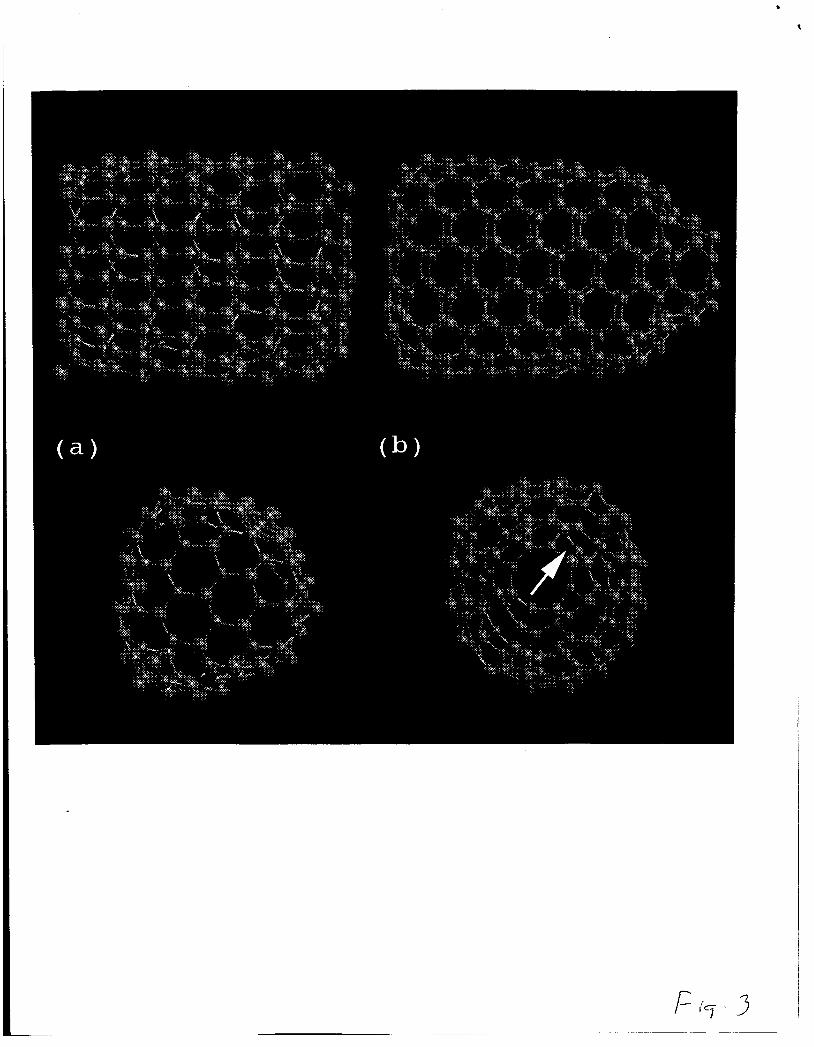
can be readily achieved through the introduction of hexagon-square pairs. In Fig. 3 a we
show a fully relaxed tip of a (12,O) BN nanotube with bending achieved via three hexagon-
square pairs. [ la] Unlike the heptagon-pentagon pair, the hexagon-square pair has two fewer
atoms resulting in sharp curvature and abrupt tube closing as seen in Fig. 3a. Although
the flat end shown in Fig. 3a corresponds to a triangular facet (three 120’ disclinations),
higher order facets are also possible with squares at each corner.
Since the hexagon-square pairs give rise to flat ends, another mechanism has to be
invoked for the pointed conical (“pencil-like”) tube closing observed in many of the BN
nanotube samples. [12] Such a closing must be achieved through a more gradual decrease in
the diameter. We propose that this can be accomplished by introducing adjacent octagon-
square pairs shown in Fig. 3b. An example of the octagon-square pair defect at the conical
end of an arm-chair tube is indicated by an arrow in the figure. These pairs contain the
same number of atoms as heptagon-pentagon pairs. The tube shown in the figure is an
GTBMD relaxed (5,5) “arm-chair’’ tube. A more gradual formation of the conical tip can
be achieved similarly by gradual insertions of the octagon-square pairs in an otherwise all
hexagonal lattice. The octagons are energetically much more stable than heptagons due to
the lack of B-B or N-N bonds. Since the octagon-square pairs must be oriented along the
tube axis for achieving the conical shape, the most likely “host” tube for such a cap must
be an “arm-chair” tube (Fig. 3b).
The “chiral” tubes, on the other hand, cannot accommodate either hexagon-square or
octagon-square pairs and are forced to have unfavorable pentagons and, possibly, heptagons
while attempting to close. As we found in our molecular dynamics simulations of the chiral
(8,2) tube, this results in the breaking up of B-B and N-N bonds with reactive dangling bonds
6

that can disrupt the smooth tube closing by forming higher coordinated structures. This
may explain the formation of amorphous-like structures found at the ends of BN nanotubes
in many cases.
This raises an important issue regarding the connection between the experimentally ob-
served tube closing vs. chirality. The fact that flat ends are seen in experiment more abun-
dantly than conical ends may indicate more abundant production of “zig-zag” tubes when
compared with “arm-chair” tubes. This is in striking contrast to the case of carbon nan-
otubes where the experimental results supported by theory, so far, indicate preponderance of
“arm-chair” nanotubes. [21] Recent experiments correlating chirality of a carbon tube with
the conductance indicate that this might not be the case even for carbon nanotubes. [22]
As shown in this work, the BN nanotubes, unlike the carbon nanotubes, show considerable
reconstruction characterized by rotational relaxation on the tube surface. For the “zig-zag”
tubes the resulting bond contraction/stretching is along the tube axis and, therefore, strain
accommodation is easier because no appreciable force is created along the circumference.
Similar reconstruction in the “arm-chair” tubes, however, results in the creation of forces
along the circumference, requiring more strain accommodation in the structure. As calcu-
lated by us, some of the strain can be relieved by a slight increase in the overall B-N bond
lengths. This gives further support to the stability of “zig-zag” tubes over the “arm-chair”
tubes.
At the time of writing this manuscript we became aware of a recent paper 1231 describing
B-B and N-N bond frustration effects during the growth of BN nanotubes. There are
significant similarities and differences between the two works. First, the significant similarity,
through two different approaches, is in the observation that frustrated B-B and N-N bonds
are not allowed, and hence odd membered rings are avoided in the growing edge [23] and
in the final equilibrium structures as predicted in this work. The significant difference is
in the final shape of the BN nanotube tips and their correlation with the structures of the
nanotubes. We conclude that experimentally observed flat tips [12] are the closure of only
zig-zag tubes with square-hexagon pairs. The “pencil-like” (conical) tapering of the tips are
7

due to the closure of only arm-chair tubes with octagon-square pairs. The relaxed chiral
tube tips cannot avoid odd membered rings and end up with amorphous tips. The work of
Blase et. al. [23] agrees with ours in that molecular dynamics relaxation for arm-chair tubes
can result in the creation of a tip containing four squares and an octagon (Fig. 3) but makes
no connection with all three shapes of the tips observed in the experiments. Focusing on
pic0 second duration MD simulation of the growth they propose that the edges of the zigzag
tubes are unstable and hence more arm chair tubes should be observed. The pic0 second
duration MD simulations are limited only to the pic0 second duration kinetic processes and
may not be a complete representation of the growth. The experimental observation of more
flat tips [la] and the accommodation of larger bond rotation induced strain parallel to the
tube axis, however, favor zig-zag over arm-chair tubes as proposed in this work.
In summary, we have presented our results of molecular dynamics simulations for BN
nanotubes showing rotation relaxation, characteristic of surface reconstruction of 111-V semi-
conductors. More interestingly, our simulations show that unlike carbon nanotubes, the
chiralities of the BN nanotubes can be determined by observing the morphologies of tube
closing. The geometries obtained using our simulations for flat and conical ends are in
striking agreement with the TEM images reported. Furthermore, we have explained the
preponderance of flat end zig-zag tubes in terms of the varying degrees of strains involved
in the surface reconstruction among tubes with different chiralities.
Part of this research (MM) was supported by NSF grant OSR 94-52895, and by the Uni-
versity of Kentucky Center for Computational Sciences. GTBMD relaxation and electronic
structure computations were performed (DS) at NAS computational facility at NASA Ames
Research Center.
8

REFERENCES
* e-mail: [email protected]
e-mail : deepak@nas. nasa. gov
[l] S. Iijima, Nature 354, 56 (1991).
**
121 J. W. Mintmire, B. I. Dunlap and C. T. White, Phys. Rev. Lett. 68, 631 (1992).
[3] R. Saito, M. Fujita, G. Dresselhaus and M. S. Dresselhaus Phys. Rev. B46, 1804 (1992).
[4] N. Hamada, S. Sawada and A. Oshiyama, Phys. Rev. Lett. 68, 1579 (1992).
[5] B. I. Dunlap, Phys. Rev. B49, 5643 (1994).
[6] M. Menon, E. Richter and K. R. Subbaswamy, J. Chem. Phys. 104, 5875 (1996).
[7] A. Rubio, J. L. Corkill, and M. L. Cohen, Phys. Rev. B 49, 5081 (1994).
[8] X. Blase, A. Rubio, S. G. Louie, and M. L. Cohen, Europhys. Lett. 28, 335 (1994).
[9] P. Gleize, M. C. Schouler, P. Gadelle, and M. Caillet, J. Mater. Sei. 29, 1575 (1994).
[lo] P. Gleize, S. Herreyre, P. Gadelle, M. Mermoux, M. C. Cheynet, and L. Abello, J.
Mater. Sci. Lett. 13, 1413 (1994).
[ll] N. G. Chopra, R. J. Luyken, K. Cherry, V. H. Crespi, M. L. Cohen, S. G. Louie, and
A. Zettl, Science 269, 966 (1995).
[12] A. Loiseau, F. Willaime, N. Demoncy, G. Hug, and H. Pascard, Phys. Rev. Lett. 76,
4737 (1996).
[13] M. Menon, K.R. Subbaswamy and M. Sawtarie, Phys. Rev. B 48, 8398 (1993).
[14] M. Menon and K.R. Subbaswamy, Phys. Rev. B 55, 9231 (1997).
[15] M. Menon, to be published.
[16] W. A. Harrison, Electronic Structure and the Properties of Solids (Freeman, San Fran-
9

cisco, 1980).
[17] R. T. Sanderson, Chemical Bonds and Bond Energy, (Academic Press),
[18] N. Hamada, S. Sawada and A. Oshiyama, Phys. Rev. Lett. 68, 1759 (1992).
[19] A. U. MacRae and G. W. Gobeli, J. Appl. Phys. 35, 1629 (1964); Physics of 111-V
compounds, edited by R. K. Willerdson and A. C. Beer (academic, New York, 1966),
Vol. 2, p. 115.
[20] L. Chico, V. H. Crespi, L. X. Benedict, S. G. Louie, and M. L. Cohen, Phys. Rev. Lett.
76, 971 (1996).
[21] A. M. Rao, E. Richter, S. Bandow, B. Chase, P. C. Eklund, K. A. Williams, S. Fang,
E<. R. Subbaswamy, M. Menon, A. Thess, R. E. Smalley, G. Dresselhaus, and M. S.
Dresselhouse, Science 275 187 (1997).
[22] J. W. G. Wildoer, L. C. Venema, A. G. Rinzler, R. E. Smally and C. Dekker, Nature
391 59 (1998); and T. W. Odom, J. L. Huang, P. Kim and C. M. Lieber, Nature 391
62 (1998).
[23] X. Blase, A. D. Vita, J.-C. Charlier and R. Car, Phys. Rev. Lett. 80 1666 (1998).
10

. c
FIGURES
FIG. 1. (a) Fully relaxed (10’0) “zigzag” BN tube (I) with a B/N ratio of 1. The boron
atoms are shown in dark circles and nitrogen atoms are shown in light circles. The surface appears
“rippled”; caused by the inward displacement of the B atoms in conjunction with the outward
movement of the N atoms. The surface relaxation is reminiscent of the (110) surface relaxation of
the 111-V semiconductors. The reconstruction is even more pronounced at the open ends.
FIG. 2. (a) Fully relaxed (a) (5 ,5 ) (11) and (b) (8’2) (111) BN tubes, also with a B/N ratio of 1.
FIG. 3. (a) Side and top view of the flat tip of (12,O) BN nanotube showing hexagon-square
pairs. Nitrogen atoms are shown in red and boron in blue. (b) Side and top view of the “pencil-like”
(conical) tube closing of the (5 ,5 ) “arm-chair” tube. The octagon-square pairs responsible for
achieving gradual closing are aligned along the tube axis. The side view in is striking agreement
with the TEM image reported in Ref. [12]
11

8
B N