Pipeline bridge crossing for mining trucks A geotechnical ...

Wang No. 498-01-03 I-55 Over Joliet Road
For Lin Engineering, Ltd.
3261 S Meadowbrook Road
Springfield, IL 62771
Submitted by
Wang Engineering, Inc.
1145 North Main Street
Lombard, IL 60148
Original Report: December 9, 2020 Revised Report: NA
STRUCTURE GEOTECHNICAL REPORT INTERSTATE 55 BRIDGE OVER JOLIET ROAD
SN 099-0028, SECTION (29-R1HP)99R-4 WILL COUNTY, ILLINOIS

Geotechnical • Construction • Environmental Quality Engineering Services Since 1982
Technical Report Documentation Page
1. Title and Subtitle Structure Geotechnical Report Interstate 55 Bridge over Joliet Road
2. Original Date: December 9, 2020Revised Date: NA
3. Report Type SGR RGR Draft Final Revised
4. Route / Section / County I-55/ (29-R1HP)99R-4 / Will
5. IDOT Contract No. 62H03
6. PTB / Item No. 193/006
7. Existing Structure Number(s) 099-0028
8. Proposed Structure Number(s) 099-0028
9. Prepared by Wang Engineering, Inc. 1145 N Main Street Lombard, IL 60148
Contributor(s) Authors: Ramesh KC, PE Nesam S. Balakumaran, P.Eng. QA/QC: Corina T. Farez, PE, PG PM: Andri A. Kurnia, PE
Contact (630) 953-9928 ext. 1025 [email protected]
10. Prepared for Lin Engineering, Ltd. 3261 S Meadowbrook Road Springfield, IL 62771
Contact(s) Fred M. Lin, PE
Contact 630-323-5168 [email protected]
11. Abstract The existing Interstate 55 bridge over Joliet Road will be widened in both northbound and southbound directions. The existing structure has a total back-to-back abutment length of 210.6 feet and out-to-out widths of 119.3 and 123.5 feet for the west abutment and east abutment, respectively. The approach embankments are estimated to have side slopes graded at 1:4 (V:H) to 1:2 (V:H). The profile grade along the I-55 will not be changed and new maximum fill height at widened embankments will be about 2 feet. This report provides geotechnical recommendations for the design and construction of the proposed bridge widening and approach embankments. The lithologic profile includes up to 7.5 feet of stiff to hard, black, blue, gray, and green silty clay to clay loam fill. Beneath the fill, the borings encountered up to 50.3 feet of stiff to hard, brown and gray clay, silty clay to silty clay loam over medium dense to very dense, brown and gray sandy loam, silt to silty loam. Groundwater was observed at depths of 3.5 to 9.75 feet bgs in three borings drilled along southbound. The approach embankments will undergo an estimated 0.2 inches or less of long-term settlement. Downdrag load allowances are not required for the abutment piles. The approach embankments with side slopes graded at 1:2 (V: H) to 1:4 (V:H) and will adequate factor of safety against global instability. The bridge abutments could be supported on metal-shell or H-piles. Selected driven MSP or steel H-piles will provide 50 to 318 kips of factored resistance for piles driven to lengths of 10 to 63 feet. The piers will be supported by shallow foundations with estimated base elevations of 725.1 feet for Pier 1 (west pier) and 724.9 feet for Pier 2 (east pier). We recommend a factored bearing resistance of 5,000 psf be used for the design of the pier footings. Temporary sheet piling is feasible except for the west abutment where a temporary soil retention system should be planned due to hard soil conditions.
12. Path to archived file
S:\Netprojects\4980103\Reports\RPT_Wang_NSB_4980103I-55OverJolietRdSGR_V01_20201209.doc

S:\Netprojects\4980103\Reports\RPT_Wang_NSB_4980103I-55OverJolietRdSGR_V01_20201209.doc i
TABLE OF CONTENTS
1.0 INTRODUCTION ............................................................................................................................................................... 1
1.1 PROPOSED STRUCTURE .............................................................................................................................................. 1
1.2 EXISTING STRUCTURE AND LAND USE ....................................................................................................................... 1
2.0 METHODS OF INVESTIGATION .................................................................................................................................. 2
2.1 FIELD INVESTIGATION................................................................................................................................................ 2
2.2 LABORATORY TESTING .............................................................................................................................................. 3
3.0 INVESTIGATION RESULTS ........................................................................................................................................... 3
3.1 LITHOLOGICAL PROFILE............................................................................................................................................. 3
3.2 GROUNDWATER CONDITIONS ..................................................................................................................................... 4
4.0 FOUNDATION ANALYSIS AND RECOMMENDATIONS ....................................................................................... 4
4.1 SEISMIC DESIGN CONSIDERATIONS ............................................................................................................................ 5
4.2 APPROACH EMBANKMENTS ....................................................................................................................................... 5
4.2.1 Settlement ........................................................................................................................................................ 5
4.2.2 Global Stability ................................................................................................................................................ 6
4.3 STRUCTURE FOUNDATIONS ........................................................................................................................................ 6
4.3.1 Driven Piles ..................................................................................................................................................... 7
4.3.2 Cast-in-Place Pier Foundations ..................................................................................................................... 12
4.3.3 Lateral Loading ............................................................................................................................................. 13
5.0 CONSTRUCTION CONSIDERATIONS ...................................................................................................................... 15
5.1 SITE PREPARATION .................................................................................................................................................. 15
5.2 EXCAVATION, DEWATERING, AND UTILITIES ............................................................................................................ 15
5.3 STAGE CONSTRUCTION ............................................................................................................................................ 16
5.4 FILLING AND BACKFILLING ...................................................................................................................................... 16
5.5 EARTHWORK OPERATIONS ..................................................................................................................................... 17
5.6 PILE INSTALLATION ................................................................................................................................................. 17
6.0 QUALIFICATIONS ........................................................................................................................................................... 18
REFERENCES ................................................................................................................................................................ 19

S:\Netprojects\4980103\Reports\RPT_Wang_NSB_4980103I-55OverJolietRdSGR_V01_20201209.doc ii
EXHIBITS
1. SITE LOCATION MAP
2. BORING LOCATION PLAN
3. SOIL PROFILE
APPENDIX A
BORING LOGS
APPENDIX B
LABORATORY TEST RESULTS
APPENDIX C
GLOBAL STABILITY ANALYSIS
APPENDIX D
GENERAL PLAN AND ELEVATION
LIST OF TABLES
Table 1:Recommended Seismic Design Parameters .............................................................................................................. 5
Table 2: Estimated Pile Lengths and Tip Elevations for 12-inch Diameter w/.25″ walls MSP ............................................. 7
Table 3: Estimated Pile Lengths and Tip Elevations for 14-inch Diameter w/.312″ walls MSP ........................................... 9
Table 4: Estimated Pile Lengths and Tip Elevations for HP12x53 Steel H Piles ................................................................. 10
Table 5: Estimated Pile Lengths and Tip Elevations for HP14x73 Steel H Piles ................................................................. 11
Table 6: Recommended Soil Parameters for Lateral Load Analysis for West Abutment-Northbound ................................ 13
Table 7: Recommended Soil Parameters for Lateral Load Analysis for West Abutment-Southbound ................................ 14
Table 8: Recommended Soil Parameters for Lateral Load Analysis for East Abutment-Northbound ................................. 14
Table 9: Recommended Soil Parameters for Lateral Load Analysis for East Abutment-Southbound ................................. 15

1145 North Main Street Lombard, Illinois 60148
Phone (630) 953-9928 www.wangeng.com
Geotechnical • Construction • Environmental Quality Engineering Services Since 1982
STRUCTURE GEOTECHNICAL REPORT INTERSTATE 55 BRIDGE OVER JOLIET ROAD
SN 099-0028, SECTION (29-R1HP)99R-4 WILL COUNTY, ILLINOIS
FOR LIN ENGINEERING, LTD.
1.0 INTRODUCTION
This report presents the results of the subsurface investigation, laboratory testing, geotechnical
evaluations, and recommendations for the widening of the Interstate 55 (I-55) dual structure Bridge
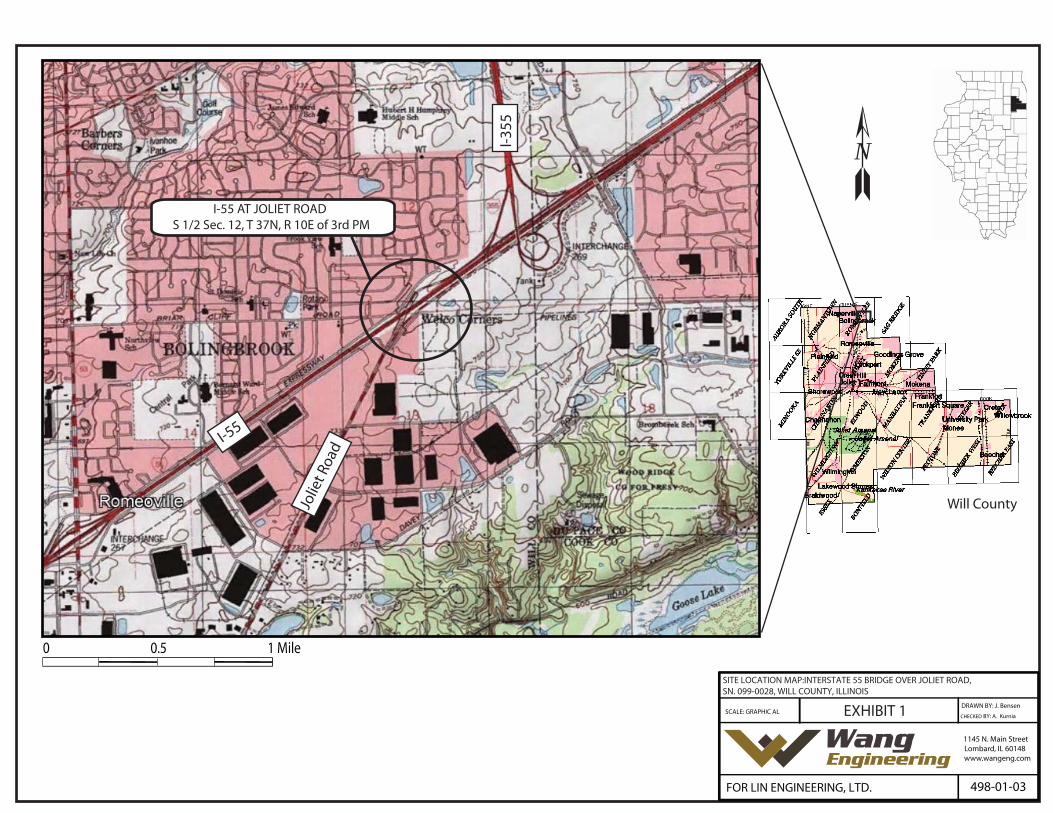
over Joliet Road in Will County, Illinois. A Site Location Map is presented as Exhibit 1.
1.1 Proposed Structure
Based on the most recent General Plan and Elevation (GPE) sheets provided by Graef on November
17, 2020, and information provided by Lin Engineering, Ltd. (Lin), Wang Engineering, Inc. (Wang)
understands the improvements to the 3-span dual structure bridge include superstructure replacement
and widening of the substructures in both the northbound and southbound bridges. The bridge deck
will be widened along the northbound lanes by 6′-7″ and since the bridge has 61.13 degree skew, the
abutments and piers of the northbound bridge need to be widened by about 13.6 feet. The southbound
bridge widening includes 13.0 feet at the west abutment and then it tapers down to 7.8 feet at the east
abutment. The profile grade along the I-55 will not be changed and new maximum fill height at
widened embankments will be about 2 feet.
Wang prepared a Structure Geotechnical Report (SGR) for initially proposed northbound widening.
This updated SGR supersedes previously submitted SGR and includes both northbound and
southbound widenings.
1.2 Existing Structure and Land Use
The original three-span dual structure was built in 1955 and repaired and widened in 1976, 1987,
1996 2002, 2009, and 2016. The structure has total back-to-back abutment length of 210.6 feet and
out-to-out widths of 119.3 feet at west abutment and 123.5 feet at east abutment. The stub abutments
are supported on two rows of concrete piles, one vertical and one batter. From the 1955 design
Wang No. 498-01-03 Interstate 55 over Joliet Road, SN 099-0028 December 9, 2020
S:\Netprojects\4980103\Reports\RPT_Wang_NSB_4980103I-55OverJolietRdSGR_V01_20201209.doc
2
drawings, the pile length is estimated to be 15 feet with 30 tons capacity. Pier 1 and Per 2 are
supported on shallow foundation. Shallow foundations were used at Pier 1 at elevation of about 725.1
feet and Pier 2 at elevation of about 724.9 feet.
The purpose of this investigation was to characterize the site soil and groundwater conditions, perform
geotechnical analyses, and provide recommendations for the design and construction of the proposed
bridge widening foundations.
2.0 METHODS OF INVESTIGATION
The following sections outline the subsurface and laboratory investigations performed by Wang.
2.1 Field Investigation
The initial subsurface investigation consisted of four structure borings for northbound bridge
widening, designated as SB-01 through SB-04, drilled by Wang from April 20 to 23, of 2020. The
borings were drilled from elevations of 748.90 and 752.04 feet along the I-55 shoulders and from
elevations of 730.96 to 731.62 feet along Joliet Road. The borings were advanced to depths of 48
to 80 feet bgs.
The latest subsurface investigation included four structure borings for southbound bridge
widening, designated as SB-05 through SB-08, drilled by Wang from October 16 to 20, 2020.
Borings SB-05 and SB-08 were drilled from elevations 750.80 and 753.33 feet from I-55 shoulders
and advanced to depths of 78.9 and 79.0 feet bgs. Borings SB-06 and SB-07 were drilled from
elevations of 733.04 and 733.62 feet from Joliet Road and advanced to depths of 59.0 to 59.9 feet
bgs.
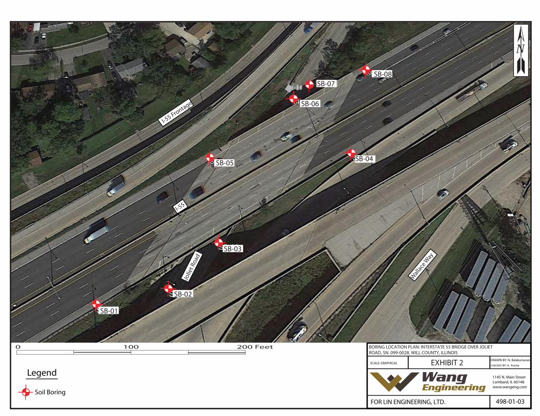
As-drilled northings and eastings were surveyed by Wang and elevations, stations, and offsets were
provided by Lin. Boring location data are presented in the Boring Logs (Appendix A) and the as-
drilled boring locations are shown in the Boring Location Plan (Exhibit 2).
A truck-mounted drilling rig, equipped with mud rotary equipment or hollow stem augers, was used
to advance and maintain open boreholes. Soil sampling was performed according to AASHTO T206,
"Penetration Test and Split Barrel Sampling of Soils." The soil was sampled at 2.5-foot intervals to 30
feet bgs and at 5-foot intervals to the boring termination depths.
Wang No. 498-01-03 Interstate 55 over Joliet Road, SN 099-0028 December 9, 2020
S:\Netprojects\4980103\Reports\RPT_Wang_NSB_4980103I-55OverJolietRdSGR_V01_20201209.doc
3
Field boring logs, prepared and maintained by a Wang field engineer, included lithological
descriptions, visual-manual soil classifications, results of Rimac and pocket penetrometer unconfined
compressive strength tests, and results of Standard Penetration Tests (SPT) recorded as blows per 6
inches of penetration. Groundwater levels were measured while drilling and at completion of each
boring.
The boreholes were backfilled upon completion with grout and/or bentonite chips and the surfaces
were restored as much as possible to its original conditions.
2.2 Laboratory Testing
The soil samples were tested in the laboratory for moisture content (AASHTO T265). Atterberg limits
(AASHTO T89 and T90) and particle size analysis (AASHTO T88) tests were performed on selected
samples. Field visual descriptions of the soil samples were verified in the laboratory and index tested
soils were classified according to the IDH Soil Classification System. The laboratory test results are
shown in the Boring Logs (Appendix A) and in the Laboratory Test Results (Appendix B).
3.0 INVESTIGATION RESULTS
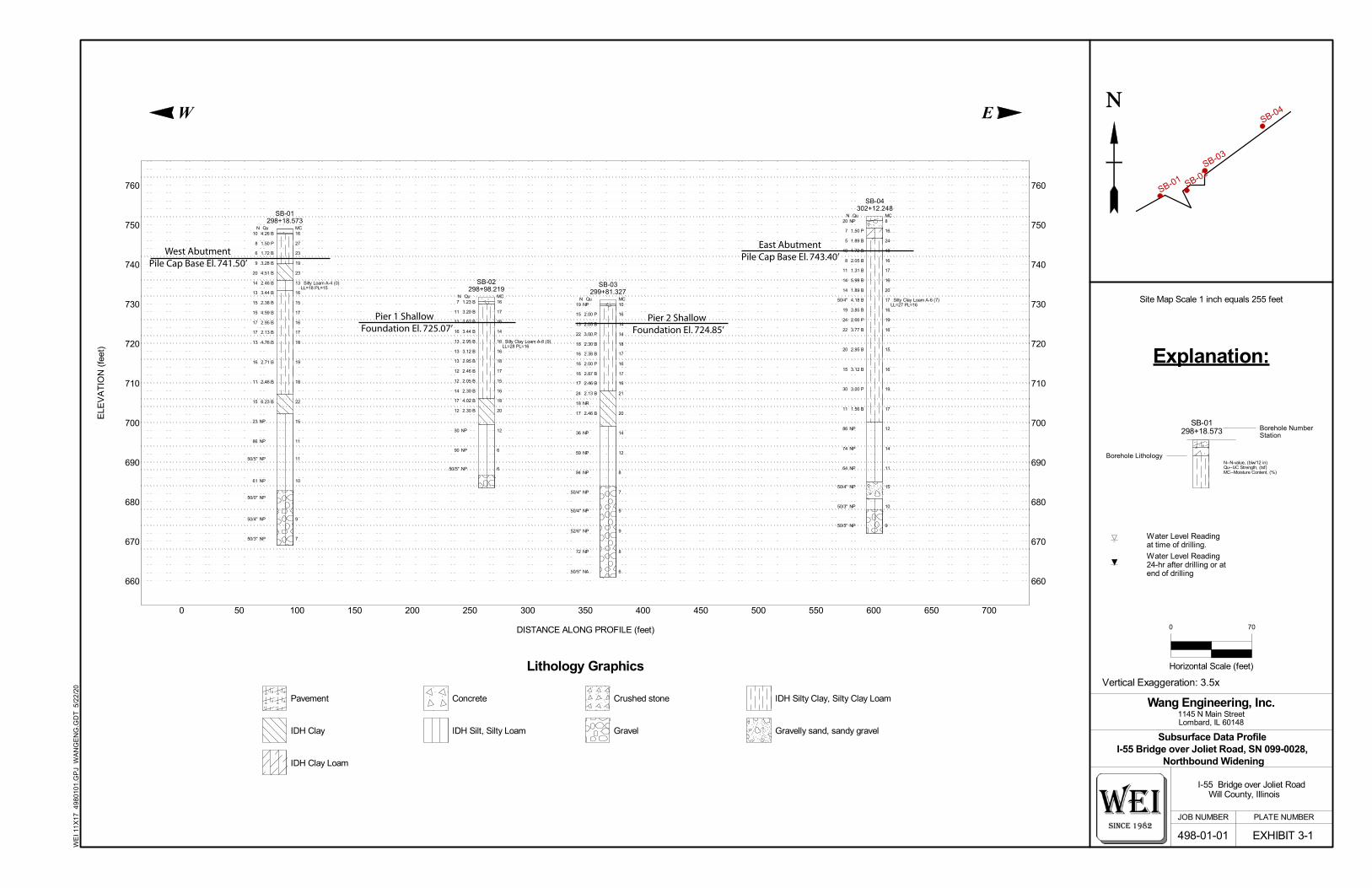
Detailed description of the soil condition encountered during the subsurface investigation is presented
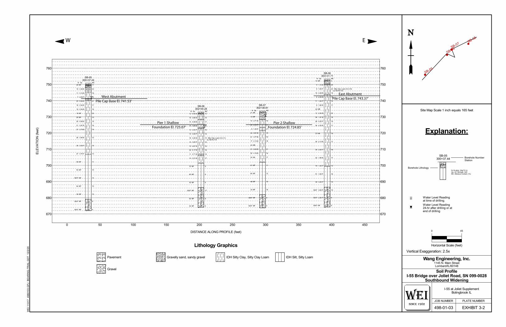
in the attached Boring Logs (Appendix A) and in the Soil Profiles (Exhibits 3-1 and 3-2). Please note
that strata contact lines represent approximate boundaries between soil types. The actual transition
between soil types in the field may be gradual in horizontal and vertical directions.
3.1 Lithological Profile
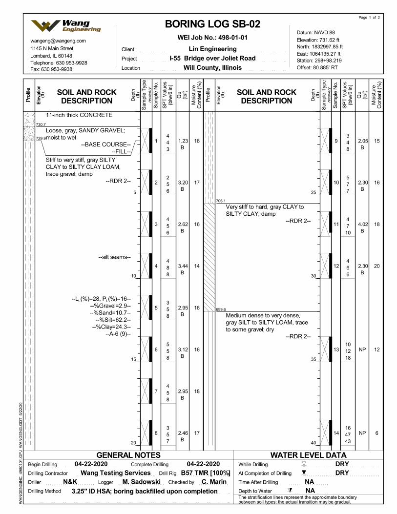
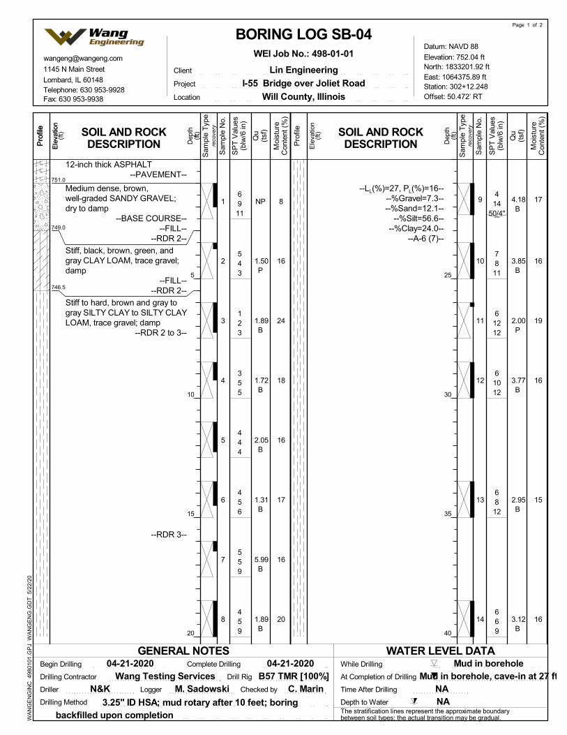
At the surface, the borings drilled along northbound I-55 encountered 1-inch thick asphalt pavement
over 11-inch thick concrete and 12-inch thick asphalt pavement. The borings drilled along southbound
I-55 revealed 12-inch thick asphalt pavement. The borings drilled along Joliet Road encountered 11
and 12-inch thick concrete. Underneath the pavements, the borings encountered 3- to 54-inch thick
sandy gravel aggregate base. In descending order, the general lithologic succession encountered
beneath the pavements includes: 1) man-made ground (fill); 2) stiff to hard clay, silty clay to silty
clay loam; and 3) medium dense to very dense sandy loam, silt to silty loam.

Wang No. 498-01-03 Interstate 55 over Joliet Road, SN 099-0028 December 9, 2020
S:\Netprojects\4980103\Reports\RPT_Wang_NSB_4980103I-55OverJolietRdSGR_V01_20201209.doc
4
1) Man-made ground (fill)
Beneath the pavements, the borings encountered up to 7.5 feet of mostly cohesive fill. The cohesive
fill consists of stiff to hard, brown, black, blue, green, and gray silty clay to clay loam fill material
with unconfined compressive strength (Qu) values of 1.5 to 6.5 tsf and moisture content values of 13
to 27%. Boring SB-05 encountered 1.3 feet of medium dense, brown sandy gravel with N value of 20
blows per foot and moisture content value of 11%.
2) Stiff to hard clay, silty clay to silty clay loam
Beneath the fill or the pavement, at elevations of 728.1 to 749.6 feet, the borings augured through up
to 50.3 feet of stiff to hard, brown to gray clay, silty clay to silty clay loam interbedded with silty
loam. At elevations of 723.1 to 746.6 feet, Borings SB-05 through SB-07 encountered 0.8 to 1.5 feet
interbedded damp to saturated silty loam layers with sand lens. This unit is characterized by Qu values
of 1.2 to 6.2 tsf and moisture content values of 10 to 24%. Laboratory index testing on samples of the
silty clay loam show liquid limit (LL) values of 27 to 33% and plastic limit (PL) values of 15 to 16%.
3) Medium dense to very dense sandy loam, silt to silty loam
At elevations of 699.0 to 706.8 feet to boring termination depths, the borings revealed medium dense
to very dense, brown and gray sandy loam, silt to silty loam. This soil unit has N-values of 23 to 99
blows per foot and moisture content values of 6 to 18%. Hard drilling conditions and samples
refusals below 700 feet elevations, indicating the presence of cobbles and boulders, were observed
throughout the layer to boring termination depths.
3.2 Groundwater Conditions
The groundwater was observed during drilling at elevations of 723 to 741 feet (3.5 to 9.75 feet bgs) in
Borings SB-05 through SB-07. Borings SB-02 and SB-06 were advanced with hollow stem augers
and found to be dry upon completion of drilling. Since the remaining borings were advanced using
mud rotary techniques from 10 feet bgs, the groundwater measurement in the borehole upon
completion of drilling was not possible. It should be noted that groundwater levels might vary with
seasonal rainfall patterns and long-term climate fluctuations or be influenced by local site conditions.
4.0 FOUNDATION ANALYSIS AND RECOMMENDATIONS
Geotechnical evaluations and recommendations for the approach embankments and substructure
foundations are included in the following sections. Based on information provided by Graef, we
Wang No. 498-01-03 Interstate 55 over Joliet Road, SN 099-0028 December 9, 2020
S:\Netprojects\4980103\Reports\RPT_Wang_NSB_4980103I-55OverJolietRdSGR_V01_20201209.doc
5
understand that LRFD criteria should be used since the abutment extensions and the pier extensions
are being design with LRFD.
4.1 Seismic Design Considerations
The seismic site class was determined in accordance with the IDOT All Geotechnical Manual
Users (AGMU) 9.1 (2009) method of analysis. The soils within the top 100 feet have a weighted
average Su value of 2.78 ksf (AASHTO; Method C controlling), and the results classify the site in
the Seismic Site Class C.
The project location belongs to the Seismic Performance Zone 1. The seismic spectral acceleration
parameters recommended for design in accordance with AASHTO LRFD Bridge Design
Specifications (2009) are summarized in Table 1. According to the IDOT Bridge Manual (2012),
liquefaction analysis is not required for sites in Seismic Performance Zone 1.
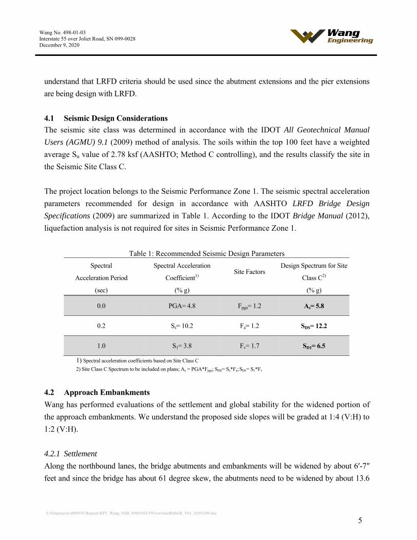
Table 1: Recommended Seismic Design Parameters
Spectral
Acceleration Period
(sec)
Spectral Acceleration
Coefficient1)
(% g)
Site Factors
Design Spectrum for Site
Class C2)
(% g)
0.0 PGA= 4.8 Fpga= 1.2 As= 5.8
0.2 Ss= 10.2 Fa= 1.2 SDS= 12.2
1.0 S1= 3.8 Fv= 1.7 SD1= 6.5
1) Spectral acceleration coefficients based on Site Class C
2) Site Class C Spectrum to be included on plans; As = PGA*Fpga; SDS= Ss*Fa; SD1= S1*Fv
4.2 Approach Embankments
Wang has performed evaluations of the settlement and global stability for the widened portion of
the approach embankments. We understand the proposed side slopes will be graded at 1:4 (V:H) to
1:2 (V:H).
4.2.1 Settlement
Along the northbound lanes, the bridge abutments and embankments will be widened by about 6′-7″
feet and since the bridge has about 61 degree skew, the abutments need to be widened by about 13.6
Wang No. 498-01-03 Interstate 55 over Joliet Road, SN 099-0028 December 9, 2020
S:\Netprojects\4980103\Reports\RPT_Wang_NSB_4980103I-55OverJolietRdSGR_V01_20201209.doc
6
feet. Settlement estimates have been made based on correlations to measured index properties. Based
on the soil conditions, we estimate the new widening area will undergo approximately 0.2 inches of
long-term consolidation settlement under the applied load resulting from 2 feet of fill material.
Along the southbound bridge widening, the west abutment will be widened by about 13.0 feet and the
east abutment will be widened by about 7.8 feet. New fill will be about 1.5 feet high and placed on the
existing embankment slope. Based on encountered soil conditions, we estimate the new widening area
will undergo long-term settlement of 0.2 inches or less.
According to IDOT Bridge Manual (2012), downdrag occurs when soil against a pile moves
downward more than 0.4 inches after driving. We estimate settlement of less than 0.4 inch, therefore
downdrag losses for the piles are not considered.
4.2.2 Global Stability
The global stability of the approach embankments was analyzed based on the soil profile described in
Section 3.1 and the cross section drawing provided by Lin. The side slope at the east abutment of
northbound bridge widening is estimated to be graded at 1:2 (V: H). The minimum required FOS for
both short (undrained) and long-term (drained) conditions is 1.5 (IDOT 2012). Slide v9.0 evaluation
exhibits employing the Bishop Simplified method of analysis are shown in Appendix C and we
estimate the slopes have a minimum undrained factor of safety (FOS) of 9.3 (Appendix C-1) and a
drained FOS of 3.3 (Appendix C-2). The FOS meets the minimum requirement. Both FOSs are
greater than the minimum IDOT required FOS of 1.5.
Based on the encountered soil profile, proposed side slope grades, and new fill height along the
existing slope at the southbound widenings are similar to the northbound widenings. Therefore, we do
not anticipate global stability concerns.
4.3 Structure Foundations
According to information provided by Graef, we understand the northbound and southbound
bridges will be widened in-kind. Based on the drawings of the existing structure, the proposed west
and east abutment pile cap base elevations are estimated at 741.5 and 743.4 feet, respectively. The
existing piers are supported by shallow foundations with estimated base elevations of 725.1 for Pier 1
(west pier), and 724.90 feet for Pier 2 (east pier).

Wang No. 498-01-03 Interstate 55 over Joliet Road, SN 099-0028 December 9, 2020
S:\Netprojects\4980103\Reports\RPT_Wang_NSB_4980103I-55OverJolietRdSGR_V01_20201209.doc
7
4.3.1 Driven Piles
IDOT specifies the maximum nominal required bearing (RNMAX) for each pile and states the factored
resistance available (RF) for steel H-piles should be based on a geotechnical resistance factor (ΦG) of
0.55 (2012). Nominal tip and side resistance were estimated using the methods and empirical
equations presented in AGMU Memorandum 10.2 – Geotechnical Pile Design (IDOT 2011). The RF
estimates are governed by the relationship RF = GRN – G(DDR+SC+Liq)IG – (p)(IS)DDL (IDOT
2012).
The existing stub abutments are supported on 14″x14″ concrete piles foundations. We understand
the widening portion of the abutments will be supported on either steel H-Piles or Metal Shell Piles
(MSP). Based on information provided by Graef, the west abutment will have a total preliminary
service load of 214 kips and a factored load of 299 kips and the east abutment will have a total
preliminary service load of 153 kips and a factored load of 221 kips. The widened pier (west) will
have a total preliminary service load of 304 kips and a factored load of 421 kips while the widened
pier (east) will have a total preliminary service load of 268 kips and a factored load of 375 kips. The
RF, RN, estimated pile tip elevations, and pile lengths for 12-inch diameter MSP with 0.25-inch thick
walls, 14-inch diameter MSP with 0.312-inch thick walls, HP12x53, and HP14x73 are summarized in
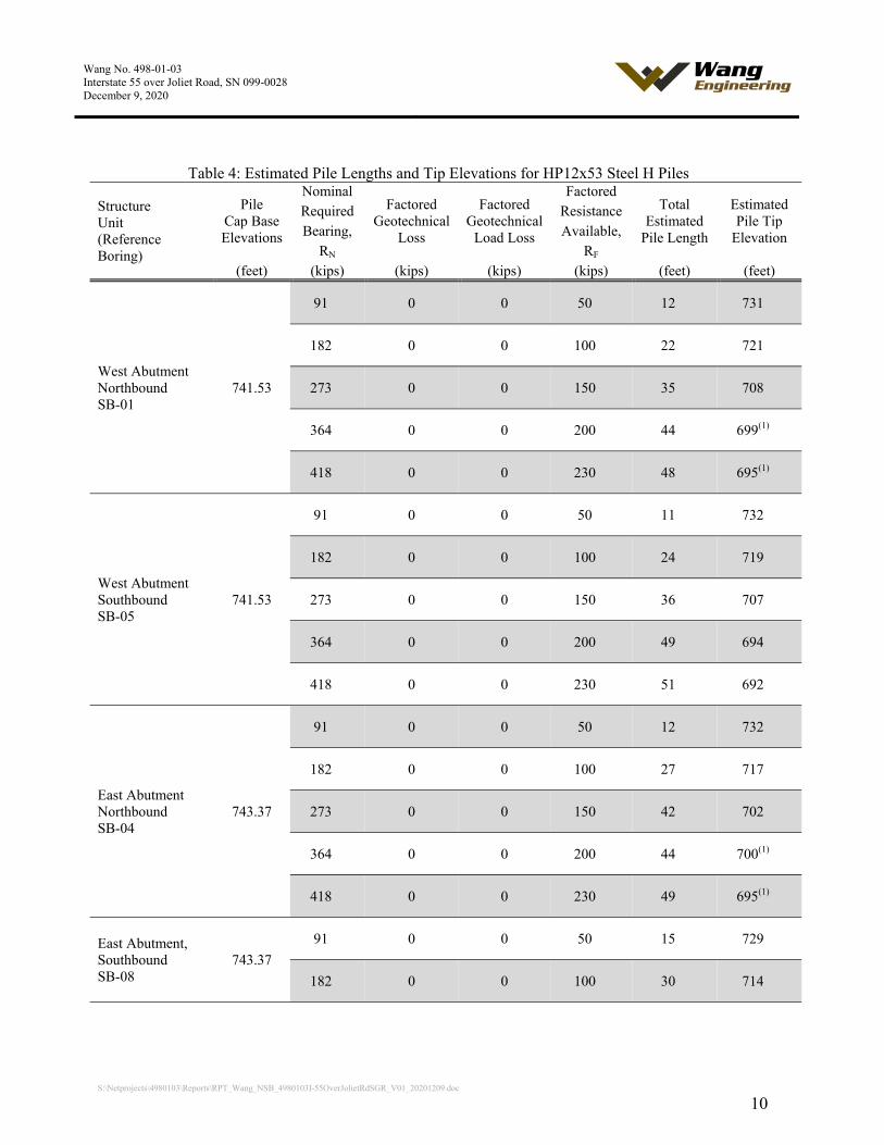
Tables 2 through Table 5. The lengths shown in the table assume a 1-foot pile embedment into the
pile cap.
We estimate the widened portions of the embankments will settle less than 0.4 inches, therefore
downdrag losses for the piles are not considered. Hard drilling conditions with possible cobbles and
boulders were encountered below 700 feet elevation. The pile should be installed with metal shoes if
driven at or below elevation 700 feet.
Table 2: Estimated Pile Lengths and Tip Elevations for 12-inch Diameter w/.25″ walls MSP
Structure Unit (Reference Boring)
Pile Cap Base Elevations
Nominal Factored
Geotechnical Loss
Factored Geotechnical
Load Loss
Factored Total
Estimated Pile Length
Estimated Pile Tip
Elevation
Required Resistance Bearing, Available,
RN RF (feet) (kips) (kips) (kips) (kips) (feet) (feet)
West Abutment Northbound SB-01
741.53
91 0 0 50 12 731
182 0 0 100 22 721

Wang No. 498-01-03 Interstate 55 over Joliet Road, SN 099-0028 December 9, 2020
S:\Netprojects\4980103\Reports\RPT_Wang_NSB_4980103I-55OverJolietRdSGR_V01_20201209.doc
8
Structure Unit (Reference Boring)
Pile Cap Base Elevations
Nominal Factored
Geotechnical Loss
Factored Geotechnical
Load Loss
Factored Total
Estimated Pile Length
Estimated Pile Tip
Elevation
Required Resistance Bearing, Available,
RN RF (feet) (kips) (kips) (kips) (kips) (feet) (feet)
273 0 0 150 33 710
364 0 0 200 40 703
West Abutment Southbound SB-05
741.53
91 0 0 50 10 733
182 0 0 100 21 722
273 0 0 150 34 709
364 0 0 200 36 707
East Abutment Northbound SB-04
743.37
91 0 0 50 13 731
182 0 0 100 20 724
273 0 0 150 32 712
364 0 0 200 44 700
East Abutment Southbound SB-08
743.37
91 0 0 50 14 730
182 0 0 100 25 719
273 0 0 150 43 701
364 0 0 200 45 699

Wang No. 498-01-03 Interstate 55 over Joliet Road, SN 099-0028 December 9, 2020
S:\Netprojects\4980103\Reports\RPT_Wang_NSB_4980103I-55OverJolietRdSGR_V01_20201209.doc
9
Table 3: Estimated Pile Lengths and Tip Elevations for 14-inch Diameter w/.312″ walls MSP
Structure Unit (Reference Boring)
Pile Cap Base Elevations
Nominal Factored
Geotechnical Loss
Factored Geotechnical
Load Loss
Factored Total
Estimated Pile Length
Estimated Pile Tip
Elevation
Required Resistance Bearing, Available,
RN RF (feet) (kips) (kips) (kips) (kips) (feet) (feet)
West Abutment Northbound SB-01
741.53
182 0 0 100 19 724
273 0 0 150 28 715
364 0 0 200 35 708
455 0 0 250 40 703
West Abutment Southbound SB-05
741.53
182 0 0 100 15 728
273 0 0 150 28 715
364 0 0 200 35 708
455 0 0 250 36 707
East Abutment Northbound SB-04
743.37
182 0 0 100 18 726
273 0 0 150 27 717
364 0 0 200 39 705
455 0 0 250 44 700
East Abutment, Southbound SB-08
743.37
182 0 0 100 19 725
273 0 0 150 34 710
364 0 0 200 44 700
455 0 0 250 44 700
Wang No. 498-01-03 Interstate 55 over Joliet Road, SN 099-0028 December 9, 2020
S:\Netprojects\4980103\Reports\RPT_Wang_NSB_4980103I-55OverJolietRdSGR_V01_20201209.doc
10
Table 4: Estimated Pile Lengths and Tip Elevations for HP12x53 Steel H Piles
Structure Unit (Reference Boring)
Pile Cap Base Elevations
Nominal Factored
Geotechnical Loss
Factored Geotechnical
Load Loss
Factored Total
Estimated Pile Length
Estimated Pile Tip
Elevation
Required Resistance Bearing, Available,
RN RF (feet) (kips) (kips) (kips) (kips) (feet) (feet)
West Abutment Northbound SB-01
741.53
91 0 0 50 12 731
182 0 0 100 22 721
273 0 0 150 35 708
364 0 0 200 44 699(1)
418 0 0 230 48 695(1)
West Abutment Southbound SB-05
741.53
91 0 0 50 11 732
182 0 0 100 24 719
273 0 0 150 36 707
364 0 0 200 49 694
418 0 0 230 51 692
East Abutment Northbound SB-04
743.37
91 0 0 50 12 732
182 0 0 100 27 717
273 0 0 150 42 702
364 0 0 200 44 700(1)
418 0 0 230 49 695(1)
East Abutment, Southbound SB-08
743.37
91 0 0 50 15 729
182 0 0 100 30 714
Wang No. 498-01-03 Interstate 55 over Joliet Road, SN 099-0028 December 9, 2020
S:\Netprojects\4980103\Reports\RPT_Wang_NSB_4980103I-55OverJolietRdSGR_V01_20201209.doc
11
Structure Unit (Reference Boring)
Pile Cap Base Elevations
Nominal Factored
Geotechnical Loss
Factored Geotechnical
Load Loss
Factored Total
Estimated Pile Length
Estimated Pile Tip
Elevation
Required Resistance Bearing, Available,
RN RF (feet) (kips) (kips) (kips) (kips) (feet) (feet)
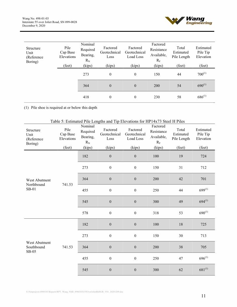
273 0 0 150 44 700(1)
364 0 0 200 54 690(1)
418 0 0 230 58 686(1)
(1) Pile shoe is required at or below this depth
Table 5: Estimated Pile Lengths and Tip Elevations for HP14x73 Steel H Piles
Structure Unit (Reference Boring)
Pile Cap Base Elevations
Nominal Factored
Geotechnical Loss
Factored Geotechnical
Load Loss
Factored Total
Estimated Pile Length
Estimated Pile Tip
Elevation
Required Resistance Bearing, Available,
RN RF (feet) (kips) (kips) (kips) (kips) (feet) (feet)
West Abutment Northbound SB-01
741.53
182 0 0 100 19 724
273 0 0 150 31 712
364 0 0 200 42 701
455 0 0 250 44 699(1)
545 0 0 300 49 694(1)
578 0 0 318 53 690(1)
West Abutment Southbound SB-05
741.53
182 0 0 100 18 725
273 0 0 150 30 713
364 0 0 200 38 705
455 0 0 250 47 696(1)
545 0 0 300 62 681(1)

Wang No. 498-01-03 Interstate 55 over Joliet Road, SN 099-0028 December 9, 2020
S:\Netprojects\4980103\Reports\RPT_Wang_NSB_4980103I-55OverJolietRdSGR_V01_20201209.doc
12
Structure Unit (Reference Boring)
Pile Cap Base Elevations
Nominal Factored
Geotechnical Loss
Factored Geotechnical
Load Loss
Factored Total
Estimated Pile Length
Estimated Pile Tip
Elevation
Required Resistance Bearing, Available,
RN RF (feet) (kips) (kips) (kips) (kips) (feet) (feet)
578 0 0 318 63 680(1)
East Abutment Northbound SB-04
743.37
182 0 0 100 20 724
273 0 0 150 34 710
364 0 0 200 42 702
455 0 0 250 45 699(1)
545 0 0 300 52 692(1)
578 0 0 318 59 685(1)
East Abutment Southbound SB-08
743.37
182 0 0 100 23 721
273 0 0 150 43 701
364 0 0 200 45 699(1)
455 0 0 250 54 690(1)
545 0 0 300 59 685(1)
578 0 0 318 61 683(1)
(1) Pile shoe is required at or below this depth
4.3.2 Cast-in-Place Pier Foundations
The existing piers are supported by shallow foundations with estimated base elevations of 725.1 feet
for Pier 1 (west pier) and 724.9 feet for Pier 2 (east pier). We understand the widening portion of the
piers will be supported on in-kind cast-in-place shallow foundations. Given the geometry and
subsurface soil conditions, a cast-in-place foundation is feasible.
Wang No. 498-01-03 Interstate 55 over Joliet Road, SN 099-0028 December 9, 2020
S:\Netprojects\4980103\Reports\RPT_Wang_NSB_4980103I-55OverJolietRdSGR_V01_20201209.doc
13
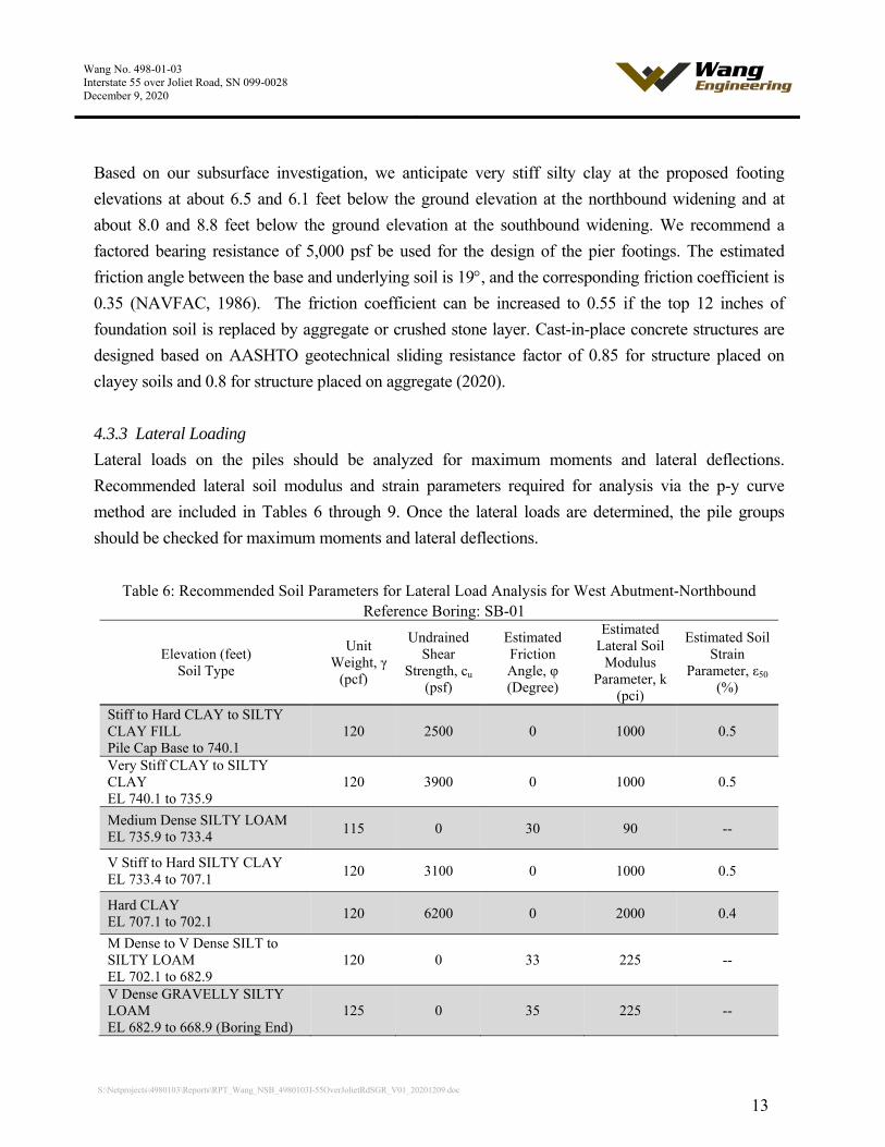
Based on our subsurface investigation, we anticipate very stiff silty clay at the proposed footing
elevations at about 6.5 and 6.1 feet below the ground elevation at the northbound widening and at
about 8.0 and 8.8 feet below the ground elevation at the southbound widening. We recommend a
factored bearing resistance of 5,000 psf be used for the design of the pier footings. The estimated
friction angle between the base and underlying soil is 19, and the corresponding friction coefficient is
0.35 (NAVFAC, 1986). The friction coefficient can be increased to 0.55 if the top 12 inches of
foundation soil is replaced by aggregate or crushed stone layer. Cast-in-place concrete structures are
designed based on AASHTO geotechnical sliding resistance factor of 0.85 for structure placed on
clayey soils and 0.8 for structure placed on aggregate (2020).
4.3.3 Lateral Loading
Lateral loads on the piles should be analyzed for maximum moments and lateral deflections.
Recommended lateral soil modulus and strain parameters required for analysis via the p-y curve
method are included in Tables 6 through 9. Once the lateral loads are determined, the pile groups
should be checked for maximum moments and lateral deflections.
Table 6: Recommended Soil Parameters for Lateral Load Analysis for West Abutment-Northbound Reference Boring: SB-01
Elevation (feet) Soil Type
Unit Weight, γ
(pcf)
Undrained Shear
Strength, cu (psf)
Estimated Friction Angle, φ (Degree)
Estimated Lateral Soil
Modulus Parameter, k
(pci)
Estimated Soil Strain
Parameter, ε50 (%)
Stiff to Hard CLAY to SILTY CLAY FILL Pile Cap Base to 740.1
120 2500 0 1000 0.5
Very Stiff CLAY to SILTY CLAY EL 740.1 to 735.9
120 3900 0 1000 0.5
Medium Dense SILTY LOAM EL 735.9 to 733.4
115 0 30 90 --
V Stiff to Hard SILTY CLAY EL 733.4 to 707.1
120 3100 0 1000 0.5
Hard CLAY EL 707.1 to 702.1
120 6200 0 2000 0.4
M Dense to V Dense SILT to SILTY LOAM EL 702.1 to 682.9
120 0 33 225 --
V Dense GRAVELLY SILTY LOAM EL 682.9 to 668.9 (Boring End)
125 0 35 225 --

Wang No. 498-01-03 Interstate 55 over Joliet Road, SN 099-0028 December 9, 2020
S:\Netprojects\4980103\Reports\RPT_Wang_NSB_4980103I-55OverJolietRdSGR_V01_20201209.doc
14
Table 7: Recommended Soil Parameters for Lateral Load Analysis for West Abutment-Southbound Reference Boring: SB-05
Elevation (feet) Soil Type
Unit Weight, γ
(pcf)
Undrained Shear
Strength, cu (psf)
Estimated Friction Angle, φ (Degree)
Estimated Lateral Soil
Modulus Parameter, k
(pci)
Estimated Soil Strain
Parameter, ε50 (%)
SILTY LOAM Pile Cap Base to 740.3
115 0 29 30 --
Stiff to Hard CLAY to SILTY CLAY FILL EL 740.3 to 706.8
120 2900 0 1000 0.5
M Dense to V Dense SILTY LOAM EL 706.8 to 679.1
120 0 33 225 --
V Dense GRAVELLY SILTY LOAM EL 679.1 to 671.9 (Boring End)
125 0 35 225 --
Table 8: Recommended Soil Parameters for Lateral Load Analysis for East Abutment-Northbound Reference Boring: SB-04
Elevation (feet) Soil Type
Unit Weight, γ
(pcf)
Undrained Shear
Strength, cu (psf)
Estimated Friction Angle, φ (Degree)
Estimated Lateral Soil
Modulus Parameter, k
(pci)
Estimated Soil Strain
Parameter, ε50 (%)
Stiff to Hard SILTY CLAY to SILTY CLAY LOAM Pile Cap Base to 700.0
120 3000 0 1000 0.5
Very Dense SILTY LOAM EL 700.0 to 685.0
120 0 33 225 --
Very Dense SANDY LOAM EL 685.0 to 680.8
120 0 34 225 --
Very Dense SILTY LOAM EL 680.8 to 678.0
120 0 33 225 --
V Dense GRAVELLY SILTY LOAM EL 678.0 to 672.0 (Boring End)
125 0 35 225 --

Wang No. 498-01-03 Interstate 55 over Joliet Road, SN 099-0028 December 9, 2020
S:\Netprojects\4980103\Reports\RPT_Wang_NSB_4980103I-55OverJolietRdSGR_V01_20201209.doc
15
Table 9: Recommended Soil Parameters for Lateral Load Analysis for East Abutment-Southbound Reference Boring: SB-08
Elevation (feet) Soil Type
Unit Weight, γ
(pcf)
Undrained Shear
Strength, cu (psf)
Estimated Friction Angle, φ (Degree)
Estimated Lateral Soil
Modulus Parameter, k
(pci)
Estimated Soil Strain
Parameter, ε50 (%)
Stiff to V Stiff SILTY CLAY Pile Cap Base to 729.8
120 1800 0 500 0.7
V Stiff to Hard SILTY CLAY EL 729.8 to 699.3
120 2600 0 1000 0.5
Dense to V Dense SILTY LOAM EL 699.3 to 686.6
125 0 33 225 --
V Dense GRAVELLY SILTY LOAM EL 686.6 to 674.3 (Boring End)
125 0 35 225 --
5.0 CONSTRUCTION CONSIDERATIONS
5.1 Site Preparation
Vegetation, surface topsoil, and debris should be cleared and stripped where the structure will be
placed. If unstable or unsuitable materials are exposed during excavation, they should be removed and
replaced with compacted structural fill as described in Section 5.4.
5.2 Excavation, Dewatering, and Utilities
Excavations should be performed in accordance with local, state, and federal regulations. The
potential effect of ground movements upon nearby utilities should be considered during construction.
Temporary excavations for construction of the bridges should be sloped at no steeper than 1:1.5
(V: H) or properly shored.
Groundwater was observed in southbound borings during drilling. We do not anticipate the need of
special dewatering systems. However, water that does accumulate in open excavations by seepage or
runoff should be immediately removed by sump pump.
The Contractor should ensure proper surface grading to prevent the pooling of water and runoff into
open excavations. Water that does accumulate into open excavations by seepage or runoff should be
Wang No. 498-01-03 Interstate 55 over Joliet Road, SN 099-0028 December 9, 2020
S:\Netprojects\4980103\Reports\RPT_Wang_NSB_4980103I-55OverJolietRdSGR_V01_20201209.doc
16
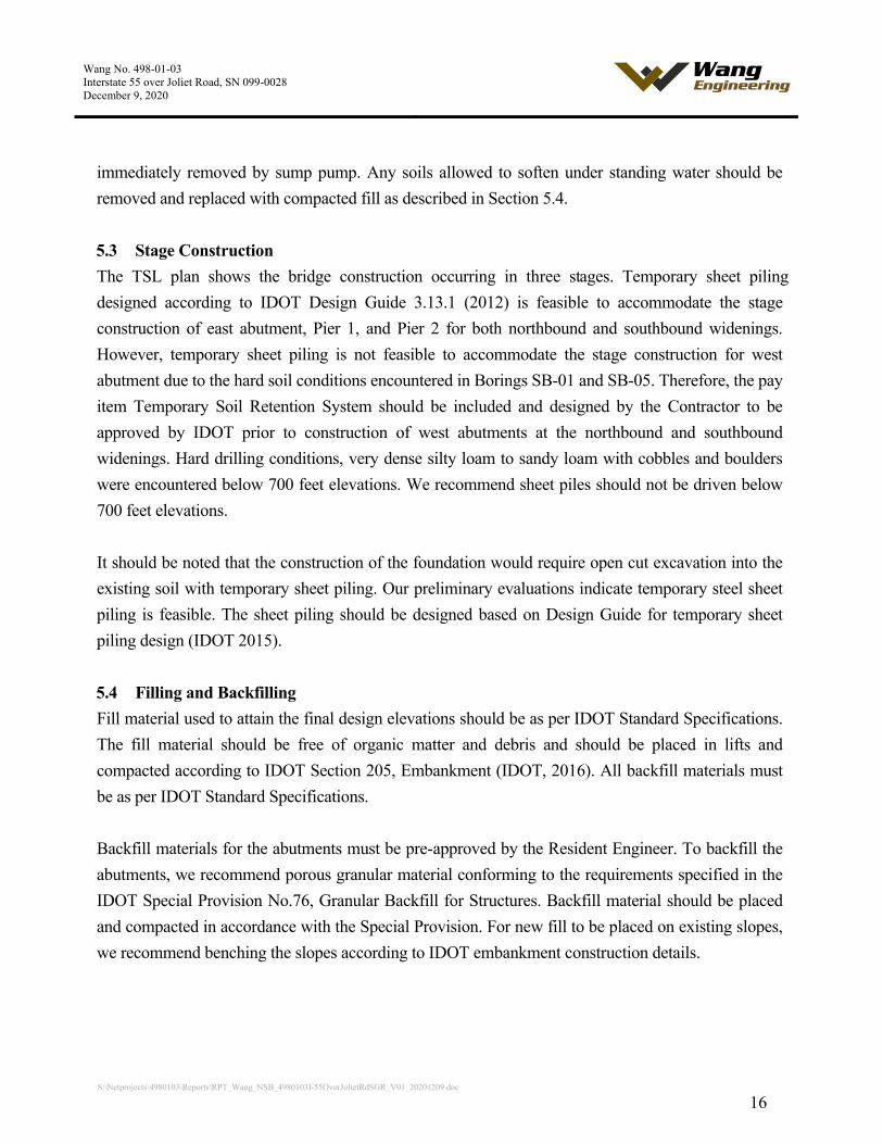
immediately removed by sump pump. Any soils allowed to soften under standing water should be
removed and replaced with compacted fill as described in Section 5.4.
5.3 Stage Construction
The TSL plan shows the bridge construction occurring in three stages. Temporary sheet piling
designed according to IDOT Design Guide 3.13.1 (2012) is feasible to accommodate the stage
construction of east abutment, Pier 1, and Pier 2 for both northbound and southbound widenings.
However, temporary sheet piling is not feasible to accommodate the stage construction for west
abutment due to the hard soil conditions encountered in Borings SB-01 and SB-05. Therefore, the pay
item Temporary Soil Retention System should be included and designed by the Contractor to be
approved by IDOT prior to construction of west abutments at the northbound and southbound
widenings. Hard drilling conditions, very dense silty loam to sandy loam with cobbles and boulders
were encountered below 700 feet elevations. We recommend sheet piles should not be driven below
700 feet elevations.
It should be noted that the construction of the foundation would require open cut excavation into the
existing soil with temporary sheet piling. Our preliminary evaluations indicate temporary steel sheet
piling is feasible. The sheet piling should be designed based on Design Guide for temporary sheet
piling design (IDOT 2015).
5.4 Filling and Backfilling
Fill material used to attain the final design elevations should be as per IDOT Standard Specifications.
The fill material should be free of organic matter and debris and should be placed in lifts and
compacted according to IDOT Section 205, Embankment (IDOT, 2016). All backfill materials must
be as per IDOT Standard Specifications.
Backfill materials for the abutments must be pre-approved by the Resident Engineer. To backfill the
abutments, we recommend porous granular material conforming to the requirements specified in the
IDOT Special Provision No.76, Granular Backfill for Structures. Backfill material should be placed
and compacted in accordance with the Special Provision. For new fill to be placed on existing slopes,
we recommend benching the slopes according to IDOT embankment construction details.
Wang No. 498-01-03 Interstate 55 over Joliet Road, SN 099-0028 December 9, 2020
S:\Netprojects\4980103\Reports\RPT_Wang_NSB_4980103I-55OverJolietRdSGR_V01_20201209.doc
17
5.5 Earthwork Operations
The required earthwork can be accomplished with conventional construction equipment. Moisture and
traffic will cause deterioration of exposed subgrade soils. Precautions should be taken by the
Contractor to prevent water erosion of the exposed subgrade. A compacted subgrade will minimize
water runoff erosion.
Earth moving operations should be scheduled to not coincide with excessive cold or wet weather
(early spring, late fall or winter). Any soil allowed to freeze or soften due to the standing water should
be removed. Wet weather can cause problems with subgrade compaction.
It is recommended that an experienced geotechnical engineer be retained to inspect the exposed
subgrade, monitor earthwork operations, and provide material inspection services during the
construction phase of this project.
5.6 Pile Installation
The driven piles shall be furnished and installed according to the requirements of IDOT Section 512,
Piling (2016). Wang recommends performing one test pile at each abutment of bridge widening
location. The test piles shall be driven to 110 percent of the nominal required bearing indicated in the
tables throughout Section 4.3. Since hard driving is expected, the pile should be installed with metal
shoes if driven at or below elevation 700 feet.

Wang No. 498-01-03 Interstate 55 over Joliet Road, SN 099-0028 December 9, 2020
S:\Netprojects\4980103\Reports\RPT_Wang_NSB_4980103I-55OverJolietRdSGR_V01_20201209.doc
18
6.0 QUALIFICATIONS
The analysis and recommendations submitted in this report are based upon the data obtained from
the borings drilled at the locations shown on the boring logs and in Exhibit 2. This report does not
reflect any variations that may occur between the borings or elsewhere on the site, variations
whose nature and extent may not become evident until the course of construction. In the event that
any changes in the design and/or location of the structure are planned, we should be timely
informed so that our recommendations can be adjusted accordingly.
It has been a pleasure to assist Lin Engineering, Ltd. and the Illinois Department of Transportation
on this project. Please call if there are any questions, or if we can be of further service.
Respectfully Submitted,
WANG ENGINEERING, INC.
Andri Kurnia, P.E. Nesam S. Balakumaran, P.Eng.
Project Manager Project Geotechnical Engineer
Corina T. Farez, P.E., P.G.
QA/QC Reviewer

Wang No. 498-01-03 Interstate 55 over Joliet Road, SN 099-0028 December 9, 2020
S:\Netprojects\4980103\Reports\RPT_Wang_NSB_4980103I-55OverJolietRdSGR_V01_20201209.doc
19
REFERENCES
AMERICAN ASSOCIATION OF STATE HIGHWAY TRANSPORTATION OFFICIALS (2020) "AASHTO LRFD
Bridge Design Specifications." United States Depart of Transportation, Washington, D.C.
IDOT (2009) "All Geotechnical Manual Users Memorandum 09.1 - Seismic Site Class Definition."
Illinois Department of Transportation.
IDOT (2011) "All Geotechnical Manual Users Memorandum 10.2 - Static Method of Estimating
Pile Length." Illinois Department of Transportation.
IDOT (2012) Bridge Manual. Illinois Department of Transportation.
IDOT (2016) Standard Specifications for Road and Bridge Construction. Illinois Department of
Transportation. 1098 pp.

1145 North Main Street Lombard, Illinois 60148
Phone (630) 953-9928 www.wangeng.com
Geotechnical • Construction • Environmental Quality Engineering Services Since 1982
EXHIBITS
N
Will County
0 0.5 1 Mile
EXHIBIT 1
1145 N. Main StreetLombard, IL 60148www.wangeng.com
DRAWN BY: J. Bensen
CHECKED BY: A. Kurnia
FOR LIN ENGINEERING, LTD. 498-01-03
SCALE: GRAPHIC AL
SITE LOCATION MAP:INTERSTATE 55 BRIDGE OVER JOLIET ROAD,SN. 099-0028, WILL COUNTY, ILLINOIS
I-55 AT JOLIET ROAD S 1/2 Sec. 12, T 37N, R 10E of 3rd PM
I-55
Jolie
t Roa
d
I-355
Legend
Soil Boring
0 100 200 Feet
SB-04
I-55
N
Jolie
t Roa
d
EXHIBIT 2
1145 N. Main StreetLombard, IL 60148www.wangeng.com
DRAWN BY: N. Balakumaran
CHECKED BY: A. Kurnia
FOR LIN ENGINEERING, LTD. 498-01-03
SCALE: GRAPHICAL
BORING LOCATION PLAN: INTERSTATE 55 BRIDGE OVER JOLIETROAD, SN. 099-0028, WILL COUNTY, ILLINOIS
SB-03
SB-02
SB-01
I-55 Frontage
Wall
ace W
ay
SB-05
SB-06
SB-07SB-08
660
670
680
690
700
710
720
730
740
750
760
0 50 100 150 200 250 300 350 400 450 500 550 600 650 700
660
670
680
690
700
710
720
730
740
750
760
16
27
23
19
23
13
16
15
17
16
17
18
19
18
22
15
11
11
10
9
7
4.26 B
1.50 P
1.72 B
3.28 B
4.51 B
2.46 B
3.44 B
2.38 B
4.59 B
2.95 B
2.13 B
4.76 B
2.71 B
2.46 B
6.23 B
NP
NP
NP
NP
NP
NP
NP
10
8
6
9
20
14
13
15
15
17
17
13
16
11
15
23
86
50/5"
61
50/0"
50/4"
50/3"
Silty Loam A-4 (0)LL=18 PL=15
MCQuN
SB-01298+18.573
16
17
16
14
16
16
18
17
15
16
18
20
12
6
6
1.23 B
3.20 B
2.62 B
3.44 B
2.95 B
3.12 B
2.95 B
2.46 B
2.05 B
2.30 B
4.02 B
2.30 B
NP
NP
NP
7
11
11
16
13
13
13
12
12
14
17
12
30
90
50/5"
Silty Clay Loam A-6 (9)LL=28 PL=16
MCQuN
SB-02298+98.219
10
16
14
14
18
17
16
17
16
21
20
14
12
8
7
9
9
8
6
NP
2.00 P
2.05 B
3.00 P
2.30 B
2.38 B
2.00 P
2.87 B
2.46 B
2.13 B
NR
2.46 B
NP
NP
NP
NP
NP
NP
NP
NA
19
15
13
22
16
16
16
16
17
24
18
17
36
59
94
50/4"
50/4"
52/6"
72
50/5"
MCQuN
SB-03299+81.327
8
16
24
18
16
17
16
20
17
16
19
16
15
16
19
17
12
14
11
15
10
9
NP
1.50 P
1.89 B
1.72 B
2.05 B
1.31 B
5.99 B
1.89 B
4.18 B
3.85 B
2.00 P
3.77 B
2.95 B
3.12 B
3.00 P
1.56 B
NP
NP
NP
NP
NP
NP
20
7
5
10
8
11
14
14
50/4"
19
24
22
20
15
30
11
86
74
64
50/4"
50/3"
50/5"
Silty Clay Loam A-6 (7)LL=27 PL=16
MCQuN
SB-04302+12.248
EXHIBIT 3-1
W
Wang Engineering, Inc.Vertical Exaggeration: 3.5x
I-55 Bridge over Joliet RoadWill County, Illinois
N--N-value, (blw/12 in)Qu--UC Strength, (tsf)MC--Moisture Content, (%)
Pavement Concrete Crushed stone IDH Silty Clay, Silty Clay Loam
IDH Clay IDH Silt, Silty Loam Gravel Gravelly sand, sandy gravel
IDH Clay Loam
Lithology Graphics
ELEV
ATIO
N (f
eet)
DISTANCE ALONG PROFILE (feet)
Horizontal Scale (feet)
PLATE NUMBER
Explanation:
JOB NUMBER
498-01-01
Site Map Scale 1 inch equals 255 feet
E
Borehole Lithology
Subsurface Data ProfileI-55 Bridge over Joliet Road, SN 099-0028,
Northbound Widening
Water Level Reading24-hr after drilling or atend of drilling
Water Level Readingat time of drilling.
Borehole NumberStation
SB-01298+18.573
1145 N Main StreetLombard, IL 60148
WEI
11X
17 4
9801
01.G
PJ W
ANG
ENG
.GD
T 5
/22/
20
0 70
SB-01 SB-02SB-03
SB-04
West Abutment Pile Cap Base El. 741.50’
East Abutment Pile Cap Base El. 743.40’
Pier 1 Shallow Foundation El. 725.07’
Pier 2 Shallow Foundation El. 724.85’
670
680
690
700
710
720
730
740
750
760
0 50 100 150 200 250 300 350 400 450
670
680
690
700
710
720
730
740
750
760
11
23
18
15
21
17
16
20
10
19
16
18
15
16
13
11
15
14
10
10
9
9
NP
3.36 B
3.12 B
2.50 P
5.08 B
2.54 B
2.54 B
NP
NP
5.08 B
2.87 B
2.79 B
3.94 B
2.50 P
3.75 P
NP
NP
NP
NP
NP
NP
NP
20
15
11
7
23
16
19
18
20
25
21
27
26
26
27
59
53
50/5"
64
36
50/4"
50/5"
MCQuN
SB-05300+37.44
13
15
17
13
16
14
15
14
16
16
16
17
9
9
8
17
8
8
6.48 B
3.85 B
4.59 B
3.69 B
2.25 P
3.00 P
3.20 B
3.00 P
4.67 B
5.17 B
2.71 B
2.21 B
NP
NP
NP
NP
NP
NP
12
15
15
15
12
13
18
14
15
24
11
14
33
60
43
50/5"
92
55
Silty Clay Loam A-6 (11)LL=30 PL=15
MCQuN
SB-06302+00.28
5
16
21
17
15
15
18
21
16
17
11
12
10
18
8
9
NP
NP
2.71 B
2.00 P
1.25 P
3.61 B
3.77 B
2.13 B
NR
3.53 B
4.18 B
NA
NP
NP
NP
NP
NP
NP
21
13
14
20
8
24
21
17
24
21
20
24
61
65
48
33
50/6"
50/5"
MCQuN
SB-07302+36.81
5
25
23
19
18
15
17
20
18
19
17
19
17
16
17
13
16
14
10
9
9
NP
1.72 B
1.00 P
3.28 B
2.05 B
1.50 P
1.80 B
NR
2.05 B
1.97 B
4.25 P
4.35 B
NA
2.13 B
2.00 P
1.80 B
1.50 P
1.00 P
3.00 P
3.00 P
2.50 P
NP
10
9
6
16
9
11
8
22
12
34
28
34
23
24
35
22
79
51
39
50/4"
50/3"
50/6"
Silty Clay Loam A-6 (15)LL=33 PL=16
MCQuN
SB-08303+31.71
EXHIBIT 3-2
W
Wang Engineering, Inc.Vertical Exaggeration: 2.5x
I-55 at Joliet SupplementBolingbrook IL
N--N-value, (blw/12 in)Qu--UC Strength, (tsf)MC--Moisture Content, (%)
Pavement Gravelly sand, sandy gravel IDH Silty Clay, Silty Clay Loam IDH Silt, Silty Loam
Gravel
Lithology Graphics
ELEV
ATIO
N (f
eet)
DISTANCE ALONG PROFILE (feet)
Horizontal Scale (feet)
PLATE NUMBER
Explanation:
JOB NUMBER
498-01-03
Site Map Scale 1 inch equals 165 feet
E
Borehole Lithology
Soil ProfileI-55 Bridge over Joliet Road, SN 099-0028
Southbound Widening
Water Level Reading24-hr after drilling or atend of drilling
Water Level Readingat time of drilling.
Borehole NumberStation
SB-05300+37.44
1145 N. Main StreetLombard/IL/60148
WEI
11X
17 4
9801
03.G
PJ B
EAR
ING
-TR
IAL.
GD
T 1
2/2/
20
0 45
SB-05
SB-06SB-07 SB-08
West Abutment Pile Cap Base El. 741.53’
Pier 1 Shallow Foundation El. 725.07’
Pier 2 Shallow Foundation El. 724.85’
East Abutment Pile Cap Base El. 743.37’
1145 North Main Street Lombard, Illinois 60148
Phone (630) 953-9928 www.wangeng.com
Geotechnical • Construction • Environmental Quality Engineering Services Since 1982
APPENDIX A
Sample Type Symbols
Split Spoon Shelby Tube
No Recovery (NR)
Auger Cu ngs
Pitcher
Rock Core
Drill Rig:
SPT = Standard Penetration Test
Qu = Unconfined Compressive
Strength Test
P = Pocket Penetrometer
S = Shear failure (Rimac)
B = Bulge failure (Rimac)
SSA = Solid Stem Auger
HSA = Hollow Stem Auger
Geotechnical • Construc on • EnvironmentalQuality Engineering Services Since 1982
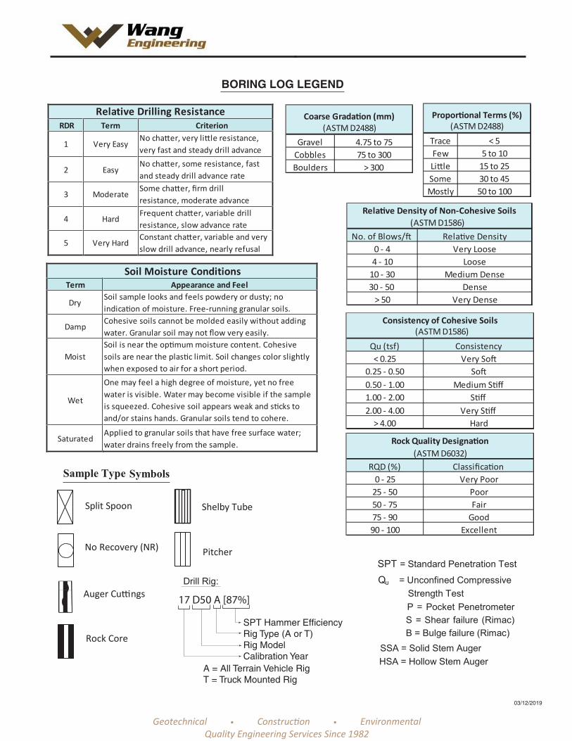
Relative Drilling ResistanceRDR Term Criterion
1 Very EasyNo cha er, very li le resistance,very fast and steady drill advance
2 EasyNo cha er, some resistance, fastand steady drill advance rate
3 ModerateSome cha er, firm drillresistance, moderate advance
4 HardFrequent cha er, variable drillresistance, slow advance rate
5 Very HardConstant cha er, variable and veryslow drill advance, nearly refusal
Soil Moisture ConditionsTerm Appearance and Feel
DrySoil sample looks and feels powdery or dusty; noindica on of moisture. Free-running granular soils.
DampCohesive soils cannot be molded easily without addingwater. Granular soil may not flow very easily.
MoistSoil is near the op mum moisture content. Cohesivesoils are near the plas c limit. Soil changes color slightlywhen exposed to air for a short period.
Wet
One may feel a high degree of moisture, yet no freewater is visible. Water may become visible if the sampleis squeezed. Cohesive soil appears weak and s cks toand/or stains hands. Granular soils tend to cohere.
SaturatedApplied to granular soils that have free surface water;water drains freely from the sample.
BORING LOG LEGEND
03/12/2019
Trace < 5Few 5 to 10Li le 15 to 25Some 30 to 45Mostly 50 to 100
Propor onal Terms (%)(ASTM D2488)
Gravel 4.75 to 75Cobbles 75 to 300Boulders > 300
Coarse Grada on (mm)(ASTM D2488)
Qu (tsf) Consistency< 0.25 Very So
0.25 - 0.50 So0.50 - 1.00 Medium S ff1.00 - 2.00 S ff2.00 - 4.00 Very S ff
> 4.00 Hard
Consistency of Cohesive Soils(ASTM D1586)
No. of Blows/ Rela ve Density0 - 4 Very Loose4 - 10 Loose
10 - 30 Medium Dense30 - 50 Dense
> 50 Very Dense
Rela ve Density of Non-Cohesive Soils(ASTM D1586)
RQD (%) Classifica on0 - 25 Very Poor
25 - 50 Poor50 - 75 Fair75 - 90 Good90 - 100 Excellent
Rock Quality Designa on(ASTM D6032)
17 D50 A [87%]
SPT Hammer EfficiencyRig Type (A or T)Rig ModelCalibration Year
A = All Terrain Vehicle RigT = Truck Mounted Rig

4.26B
1.50P
1.72B
3.28B
4.51B
2.46B
3.44B
2.38B
4.59B
2.95B
2.13B
4.76B
2.71B
2.46B
1
2
3
4
5
6
7
8
9
10
11
12
13
14
546
544
233
236
4713
477
467
578
478
589
589
667
579
556
16
27
23
19
23
13
16
15
17
16
17
18
19
18
748.8
747.9747.6
740.1
735.9
733.4
1-inch thick ASPHALT--PAVEMENT--
11-inch thick CONCRETE
Brown SANDY GRAVEL; dry--AGGREGATE BASE--
Stiff to hard, black, blue, gray andgreen, SILTY CLAY, trace gravel;damp
--FILL----RDR 2--
Very stiff to hard, brown and grayCLAY to SILTY CLAY, tracegravel; damp
--RDR 2--
Very stiff, brown and gray SILTYLOAM, little gravel; damp
--RDR 2----LL(%)=18 PL(%)=15--
--%Gravel=13.3----%Sand=27.3--
--%Silt=49.5----%Clay=9.9--
--A-4 (0)--
Very stiff to hard, gray SILTYCLAY, trace gravel; damp
--RDR 2--
5
10
15
20
Pro
file
Fax: 630 953-9938
(blw
/6 in
)
Offset: 47.079’ RT
Ele
vatio
n
04-20-2020WATER LEVEL DATA
reco
very
I-55 Bridge over Joliet Road
reco
very
Datum: NAVD 88
Sam
ple
Typ
e
(ft)
GENERAL NOTES
WEI Job No.: 498-01-01
BORING LOG SB-01
Logger
N&K NAM. Sadowski
Page 1 of 2
Qu
Moi
stur
e
At Completion of Drilling Mud in borehole
NAC. Marin
Qu
(ft)
(ft)
East: 1064050.57 ft
Drilling Contractor
While Drilling
Station: 298+18.573
Pro
file
Ele
vatio
n
Time After Drilling
Mud in borehole
Dep
th
Lombard, IL 60148
Dep
th
Moi
stur
e
(tsf
)
(ft)
Wang Testing Services
Con
tent
(%
)
Client
04-21-2020
Sam
ple
Typ
e
ft
Telephone: 630 953-9928Location
Checked by
Depth to Water
Sam
ple
No.
Sam
ple
No.
1145 N Main Street
(tsf
)
Con
tent
(%
)
Lin Engineering
Drilling Method
Driller
Begin Drilling
Pro
file
North: 1832980.20 ft
B57 TMR [100%]
(blw
/6 in
)
Project
Elevation: 748.90 ftE
leva
tion
SOIL AND ROCKDESCRIPTION
3.25" ID HSA; mud rotary after 10 feet; boringbackfilled upon completion
Will County, Illinois
Complete Drilling
SOIL AND ROCKDESCRIPTION
Drill Rig
The stratification lines represent the approximate boundarybetween soil types; the actual transition may be gradual.
SP
T V
alue
s
SP
T V
alue
s
WA
NG
EN
GIN
C 4
9801
01.G
PJ
WA
NG
EN
G.G
DT
5/2
2/2
0
25
30
35
40
6.23B
NP
NP
NP
NP
NP
NP
NP
15
16
17
18
19
20
21
22
678
41211
314145
50/5"
163427
50/0"
3150/4"
4150/3"
22
15
11
11
10
9
7
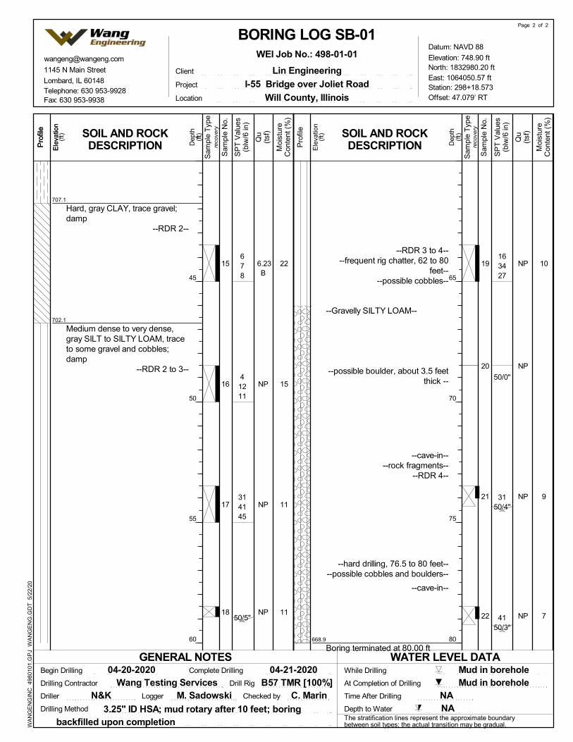
707.1
702.1
668.9
Hard, gray CLAY, trace gravel;damp
--RDR 2--
Medium dense to very dense,gray SILT to SILTY LOAM, traceto some gravel and cobbles;damp
--RDR 2 to 3--
--RDR 3 to 4----frequent rig chatter, 62 to 80
feet----possible cobbles--
--Gravelly SILTY LOAM--
--possible boulder, about 3.5 feetthick --
--cave-in----rock fragments--
--RDR 4--
--hard drilling, 76.5 to 80 feet----possible cobbles and boulders--
--cave-in--
Boring terminated at 80.00 ft
45
50
55
60
Pro
file
Fax: 630 953-9938
(blw
/6 in
)
Offset: 47.079’ RT
Ele
vatio
n
04-20-2020WATER LEVEL DATA
reco
very
I-55 Bridge over Joliet Road
reco
very
Datum: NAVD 88
Sam
ple
Typ
e
(ft)
GENERAL NOTES
WEI Job No.: 498-01-01
BORING LOG SB-01
Logger
N&K NAM. Sadowski
Page 2 of 2
Qu
Moi
stur
e
At Completion of Drilling Mud in borehole
NAC. Marin
Qu
(ft)
(ft)
East: 1064050.57 ft
Drilling Contractor
While Drilling
Station: 298+18.573
Pro
file
Ele
vatio
n
Time After Drilling
Mud in borehole
Dep
th
Lombard, IL 60148
Dep
th
Moi
stur
e
(tsf
)
(ft)
Wang Testing Services
Con
tent
(%
)
Client
04-21-2020
Sam
ple
Typ
e
ft
Telephone: 630 953-9928Location
Checked by
Depth to Water
Sam
ple
No.
Sam
ple
No.
1145 N Main Street
(tsf
)
Con
tent
(%
)
Lin Engineering
Drilling Method
Driller
Begin Drilling
Pro
file
North: 1832980.20 ft
B57 TMR [100%]
(blw
/6 in
)
Project
Elevation: 748.90 ftE
leva
tion
SOIL AND ROCKDESCRIPTION
3.25" ID HSA; mud rotary after 10 feet; boringbackfilled upon completion
Will County, Illinois
Complete Drilling
SOIL AND ROCKDESCRIPTION
Drill Rig
The stratification lines represent the approximate boundarybetween soil types; the actual transition may be gradual.
SP
T V
alue
s
SP
T V
alue
s
WA
NG
EN
GIN
C 4
9801
01.G
PJ
WA
NG
EN
G.G
DT
5/2
2/2
0
65
70
75
80
1.23B
3.20B
2.62B
3.44B
2.95B
3.12B
2.95B
2.46B
2.05B
2.30B
4.02B
2.30B
NP
NP
1
2
3
4
5
6
7
8
9
10
11
12
13
14
443
256
456
488
358
558
458
357
348
577
4710
466
101218
164743
16
17
16
14
16
16
18
17
15
16
18
20
12
6
730.7
729.9
706.1
699.6
11-inch thick CONCRETE
Loose, gray, SANDY GRAVEL;moist to wet
--BASE COURSE----FILL--
Stiff to very stiff, gray SILTYCLAY to SILTY CLAY LOAM,trace gravel; damp
--RDR 2--
--silt seams--
--LL(%)=28, PL(%)=16----%Gravel=2.9----%Sand=10.7--
--%Silt=62.2----%Clay=24.3--
--A-6 (9)--
Very stiff to hard, gray CLAY toSILTY CLAY; damp
--RDR 2--
Medium dense to very dense,gray SILT to SILTY LOAM, traceto some gravel; dry
--RDR 2--
5
10
15
20
Pro
file
Fax: 630 953-9938
(blw
/6 in
)
Offset: 80.885’ RT
Ele
vatio
n
04-22-2020WATER LEVEL DATA
reco
very
I-55 Bridge over Joliet Road
reco
very
Datum: NAVD 88
Sam
ple
Typ
e
(ft)
GENERAL NOTES
WEI Job No.: 498-01-01
BORING LOG SB-02
Logger
N&K NAM. Sadowski
Page 1 of 2
Qu
Moi
stur
e
At Completion of Drilling DRY
NAC. Marin
Qu
(ft)
(ft)
East: 1064135.27 ft
Drilling Contractor
While Drilling
Station: 298+98.219
Pro
file
Ele
vatio
n
Time After Drilling
DRY
Dep
th
Lombard, IL 60148
Dep
th
Moi
stur
e
(tsf
)
(ft)
Wang Testing Services
Con
tent
(%
)
Client
04-22-2020
Sam
ple
Typ
e
ft
Telephone: 630 953-9928Location
Checked by
Depth to Water
Sam
ple
No.
Sam
ple
No.
1145 N Main Street
(tsf
)
Con
tent
(%
)
Lin Engineering
Drilling Method
Driller
Begin Drilling
Pro
file
North: 1832997.85 ft
B57 TMR [100%]
(blw
/6 in
)
Project
Elevation: 731.62 ftE
leva
tion
SOIL AND ROCKDESCRIPTION
3.25" ID HSA; boring backfilled upon completion
Will County, Illinois
Complete Drilling
SOIL AND ROCKDESCRIPTION
Drill Rig
The stratification lines represent the approximate boundarybetween soil types; the actual transition may be gradual.
SP
T V
alue
s
SP
T V
alue
s
WA
NG
EN
GIN
C 4
9801
01.G
PJ
WA
NG
EN
G.G
DT
5/2
2/2
0
25
30
35
40

NP15 4750/5"
6
683.6
--RDR 2 to 4----frequent rig chatter, 42 to 48
feet----possible cobbles--
--rock fragments--
--very hard, steady drilling----possible cobbles and boulders--
Boring terminated at 48.00 ft
45
50
55
60
Pro
file
Fax: 630 953-9938
(blw
/6 in
)
Offset: 80.885’ RT
Ele
vatio
n
04-22-2020WATER LEVEL DATA
reco
very
I-55 Bridge over Joliet Road
reco
very
Datum: NAVD 88
Sam
ple
Typ
e
(ft)
GENERAL NOTES
WEI Job No.: 498-01-01
BORING LOG SB-02
Logger
N&K NAM. Sadowski
Page 2 of 2
Qu
Moi
stur
e
At Completion of Drilling DRY
NAC. Marin
Qu
(ft)
(ft)
East: 1064135.27 ft
Drilling Contractor
While Drilling
Station: 298+98.219
Pro
file
Ele
vatio
n
Time After Drilling
DRY
Dep
th
Lombard, IL 60148
Dep
th
Moi
stur
e
(tsf
)
(ft)
Wang Testing Services
Con
tent
(%
)
Client
04-22-2020
Sam
ple
Typ
e
ft
Telephone: 630 953-9928Location
Checked by
Depth to Water
Sam
ple
No.
Sam
ple
No.
1145 N Main Street
(tsf
)
Con
tent
(%
)
Lin Engineering
Drilling Method
Driller
Begin Drilling
Pro
file
North: 1832997.85 ft
B57 TMR [100%]
(blw
/6 in
)
Project
Elevation: 731.62 ftE
leva
tion
SOIL AND ROCKDESCRIPTION
3.25" ID HSA; boring backfilled upon completion
Will County, Illinois
Complete Drilling
SOIL AND ROCKDESCRIPTION
Drill Rig
The stratification lines represent the approximate boundarybetween soil types; the actual transition may be gradual.
SP
T V
alue
s
SP
T V
alue
s
WA
NG
EN
GIN
C 4
9801
01.G
PJ
WA
NG
EN
G.G
DT
5/2
2/2
0

NP
2.00P
2.05B
3.00P
2.30B
2.38B
2.00P
2.87B
2.46B
2.13B
NR
2.46B
NP
NP
1
2
3
4
5
6
7
8
9
10
11
12
13
14
13127
478
467
51012
388
479
579
588
789
6915
999
598
141719
211940
10
16
14
14
18
17
16
17
16
21
20
14
12
730.0
729.6
708.0
699.0
12-inch thick CONCRETE
Medium dense, gray, well-gradedSANDY GRAVEL; dry
--BASE COURSE--
Very stiff, gray SILTY CLAY,trace gravel
--RDR 2--
--LL(%)=26, PL(%)=15----%Gravel=3.4----%Sand=10.8--
--%Silt=63.9----%Clay=21.9--
--A-6 (7)--
--frequent rig chatter, 20.5 to 25feet--
--possible cobbles--
Very stiff, gray CLAY to SILTYCLAY, trace gravel; damp
--RDR 2 to 3--
Dense to very dense, gray SILTto SILTY LOAM, trace to somegravel; damp
--RDR 2 to 3--
5
10
15
20
Pro
file
Fax: 630 953-9938
(blw
/6 in
)
Offset: 62.156’ RT
Ele
vatio
n
04-23-2020WATER LEVEL DATA
reco
very
I-55 Bridge over Joliet Road
reco
very
Datum: NAVD 88
Sam
ple
Typ
e
(ft)
GENERAL NOTES
WEI Job No.: 498-01-01
BORING LOG SB-03
Logger
N&K NAM. Sadowski
Page 1 of 2
Qu
Moi
stur
e
At Completion of Drilling Mud in borehole
NAC. Marin
Qu
(ft)
(ft)
East: 1064192.86 ft
Drilling Contractor
While Drilling
Station: 299+81.327
Pro
file
Ele
vatio
n
Time After Drilling
DRY
Dep
th
Lombard, IL 60148
Dep
th
Moi
stur
e
(tsf
)
(ft)
Wang Testing Services
Con
tent
(%
)
Client
04-24-2020
Sam
ple
Typ
e
ft
Telephone: 630 953-9928Location
Checked by
Depth to Water
Sam
ple
No.
Sam
ple
No.
1145 N Main Street
(tsf
)
Con
tent
(%
)
Lin Engineering
Drilling Method
Driller
Begin Drilling
Pro
file
North: 1833060.63 ft
B57 TMR [100%]
(blw
/6 in
)
Project
Elevation: 730.96 ftE
leva
tion
SOIL AND ROCKDESCRIPTION
3.25" ID HSA; mud rotary after 10 feet; boringbackfilled upon completion
Will County, Illinois
Complete Drilling
SOIL AND ROCKDESCRIPTION
Drill Rig
The stratification lines represent the approximate boundarybetween soil types; the actual transition may be gradual.
SP
T V
alue
s
SP
T V
alue
s
WA
NG
EN
GIN
C 4
9801
01.G
PJ
WA
NG
EN
G.G
DT
5/2
2/2
0
25
30
35
40

NP
NP
NP
NP
NP15
16
17
18
19
20
324549
2430
50/4"
4850/4"
3752/6"
233240
3150/5"
8
7
9
9
8
6
661.0
--frequent rig chatter, 42 to 70feet--
--possible cobbles--
--hard drilling, 47 to 70 feet----cave-in--
--possible cobbles and boulders----RDR 3 to 4--
--possible cobbles--
--cave-in--
--possible cobbles--
--possible cobbles--
Boring terminated at 70.00 ft
45
50
55
60
Pro
file
Fax: 630 953-9938
(blw
/6 in
)
Offset: 62.156’ RT
Ele
vatio
n
04-23-2020WATER LEVEL DATA
reco
very
I-55 Bridge over Joliet Road
reco
very
Datum: NAVD 88
Sam
ple
Typ
e
(ft)
GENERAL NOTES
WEI Job No.: 498-01-01
BORING LOG SB-03
Logger
N&K NAM. Sadowski
Page 2 of 2
Qu
Moi
stur
e
At Completion of Drilling Mud in borehole
NAC. Marin
Qu
(ft)
(ft)
East: 1064192.86 ft
Drilling Contractor
While Drilling
Station: 299+81.327
Pro
file
Ele
vatio
n
Time After Drilling
DRY
Dep
th
Lombard, IL 60148
Dep
th
Moi
stur
e
(tsf
)
(ft)
Wang Testing Services
Con
tent
(%
)
Client
04-24-2020
Sam
ple
Typ
e
ft
Telephone: 630 953-9928Location
Checked by
Depth to Water
Sam
ple
No.
Sam
ple
No.
1145 N Main Street
(tsf
)
Con
tent
(%
)
Lin Engineering
Drilling Method
Driller
Begin Drilling
Pro
file
North: 1833060.63 ft
B57 TMR [100%]
(blw
/6 in
)
Project
Elevation: 730.96 ftE
leva
tion
SOIL AND ROCKDESCRIPTION
3.25" ID HSA; mud rotary after 10 feet; boringbackfilled upon completion
Will County, Illinois
Complete Drilling
SOIL AND ROCKDESCRIPTION
Drill Rig
The stratification lines represent the approximate boundarybetween soil types; the actual transition may be gradual.
SP
T V
alue
s
SP
T V
alue
s
WA
NG
EN
GIN
C 4
9801
01.G
PJ
WA
NG
EN
G.G
DT
5/2
2/2
0
65
70
75
80
NP
1.50P
1.89B
1.72B
2.05B
1.31B
5.99B
1.89B
4.18B
3.85B
2.00P
3.77B
2.95B
3.12B
1
2
3
4
5
6
7
8
9
10
11
12
13
14
6911
543
123
355
444
456
559
459
414
50/4"
7811
61212
61012
6812
669
8
16
24
18
16
17
16
20
17
16
19
16
15
16
751.0
749.0
746.5
12-inch thick ASPHALT--PAVEMENT--
Medium dense, brown,well-graded SANDY GRAVEL;dry to damp
--BASE COURSE----FILL--
--RDR 2--
Stiff, black, brown, green, andgray CLAY LOAM, trace gravel;damp
--FILL----RDR 2--
Stiff to hard, brown and gray togray SILTY CLAY to SILTY CLAYLOAM, trace gravel; damp
--RDR 2 to 3--
--RDR 3--
--LL(%)=27, PL(%)=16----%Gravel=7.3----%Sand=12.1--
--%Silt=56.6----%Clay=24.0--
--A-6 (7)--
5
10
15
20
Pro
file
Fax: 630 953-9938
(blw
/6 in
)
Offset: 50.472’ RT
Ele
vatio
n
04-21-2020WATER LEVEL DATA
reco
very
I-55 Bridge over Joliet Road
reco
very
Datum: NAVD 88
Sam
ple
Typ
e
(ft)
GENERAL NOTES
WEI Job No.: 498-01-01
BORING LOG SB-04
Logger
N&K NAM. Sadowski
Page 1 of 2
Qu
Moi
stur
e
At Completion of Drilling Mud in borehole, cave-in at 27 ft
NAC. Marin
Qu
(ft)
(ft)
East: 1064375.89 ft
Drilling Contractor
While Drilling
Station: 302+12.248
Pro
file
Ele
vatio
n
Time After Drilling
Mud in borehole
Dep
th
Lombard, IL 60148
Dep
th
Moi
stur
e
(tsf
)
(ft)
Wang Testing Services
Con
tent
(%
)
Client
04-21-2020
Sam
ple
Typ
e
ft
Telephone: 630 953-9928Location
Checked by
Depth to Water
Sam
ple
No.
Sam
ple
No.
1145 N Main Street
(tsf
)
Con
tent
(%
)
Lin Engineering
Drilling Method
Driller
Begin Drilling
Pro
file
North: 1833201.92 ft
B57 TMR [100%]
(blw
/6 in
)
Project
Elevation: 752.04 ftE
leva
tion
SOIL AND ROCKDESCRIPTION
3.25" ID HSA; mud rotary after 10 feet; boringbackfilled upon completion
Will County, Illinois
Complete Drilling
SOIL AND ROCKDESCRIPTION
Drill Rig
The stratification lines represent the approximate boundarybetween soil types; the actual transition may be gradual.
SP
T V
alue
s
SP
T V
alue
s
WA
NG
EN
GIN
C 4
9801
01.G
PJ
WA
NG
EN
G.G
DT
5/2
2/2
0
25
30
35
40

3.00P
1.56B
NP
NP
NP
NP
NP
NP
15
16
17
18
19
20
21
22
81515
447
294046
253539
212935
3050/4"
4950/3"
50/5"
19
17
12
14
11
15
10
9
700.0
685.0
680.8
672.0
--frequent rig chatter, at 52 feet----possible cobbles--
Very dense, gray SILTY LOAM,trace gravel and cobbles; damp
--RDR 2 to 3--
Very dense, gray SANDY LOAM,few gravel; damp
--RDR 3----frequent rig chatter, 67 to 80
feet----possible cobbles--
Very dense, gray SILTY LOAM,little to some garvel; damp tomoist
--rock fragments----RDR 3 to 4--
--very hard, steady drilling----possible cobbles and boulders--
Boring terminated at 80.00 ft
45
50
55
60
Pro
file
Fax: 630 953-9938
(blw
/6 in
)
Offset: 50.472’ RT
Ele
vatio
n
04-21-2020WATER LEVEL DATA
reco
very
I-55 Bridge over Joliet Road
reco
very
Datum: NAVD 88
Sam
ple
Typ
e
(ft)
GENERAL NOTES
WEI Job No.: 498-01-01
BORING LOG SB-04
Logger
N&K NAM. Sadowski
Page 2 of 2
Qu
Moi
stur
e
At Completion of Drilling Mud in borehole, cave-in at 27 ft
NAC. Marin
Qu
(ft)
(ft)
East: 1064375.89 ft
Drilling Contractor
While Drilling
Station: 302+12.248
Pro
file
Ele
vatio
n
Time After Drilling
Mud in borehole
Dep
th
Lombard, IL 60148
Dep
th
Moi
stur
e
(tsf
)
(ft)
Wang Testing Services
Con
tent
(%
)
Client
04-21-2020
Sam
ple
Typ
e
ft
Telephone: 630 953-9928Location
Checked by
Depth to Water
Sam
ple
No.
Sam
ple
No.
1145 N Main Street
(tsf
)
Con
tent
(%
)
Lin Engineering
Drilling Method
Driller
Begin Drilling
Pro
file
North: 1833201.92 ft
B57 TMR [100%]
(blw
/6 in
)
Project
Elevation: 752.04 ftE
leva
tion
SOIL AND ROCKDESCRIPTION
3.25" ID HSA; mud rotary after 10 feet; boringbackfilled upon completion
Will County, Illinois
Complete Drilling
SOIL AND ROCKDESCRIPTION
Drill Rig
The stratification lines represent the approximate boundarybetween soil types; the actual transition may be gradual.
SP
T V
alue
s
SP
T V
alue
s
WA
NG
EN
GIN
C 4
9801
01.G
PJ
WA
NG
EN
G.G
DT
5/2
2/2
0
65
70
75
80

NP
3.36B
3.12B
2.50P
5.08B
2.54B
2.54B
NP
3.00P
5.08B
2.87B
2.79B
3.94B
2.50P
1
2
3
4
5
6
7
8
9
10
11
12
13
14
6614
869
447
434
71013
679
7910
7711
10119
81114
10912
81017
81115
81016
11
23
18
15
21
17
16
20
10
19
16
18
15
16
749.8749.6
749.1
747.8
746.6
745.3
741.1
740.3
12-inch thick ASPHALT--PAVEMENT--
Gray SANDY GRAVEL; damp--AGGREGATE BASE--
Hard, brown and black SILTYCLAY, trace gravel
--FILL--
Medium dense, brown SANDYGRAVEL; damp
--FILL---- RDR 2 --
Very stiff, brown SILTY CLAY,trace gravel
-- RDR 2--
Brown SILTY LOAM; damp-- RDR 2--
Very stiff, brown SILTY CLAY,trace gravel
-- RDR 2--
Brown SILTY LOAM--saturated sand lens--
Very stiff to hard, gray SILTYCLAY, trace gravel
-- RDR 2 to 3--
--rig chatter, possible cobbles----gravels in spoon--
5
10
15
20
Pro
file
Fax: 6309539938
(blw
/6 in
)
Offset: 56.50' LT
Ele
vatio
n
11-18-2020WATER LEVEL DATA
reco
very
I-55 at Joliet Supplement
reco
very
Datum: NAVD 88
Sam
ple
Typ
e
(ft)
GENERAL NOTES
WEI Job No.: 498-01-03
BORING LOG SB-05
Logger
R & M NAE. Yim
Page 1 of 2
Qu
Moi
stur
e
At Completion of Drilling Mud
NANSB
Qu
(ft)
(ft)
East: 1064171.34 ft
Drilling Contractor
While Drilling
Station: 300+37.44
Pro
file
Ele
vatio
n
Time After Drilling
9.75 ft
Dep
th
Lombard/IL/60148
Dep
th
Moi
stur
e
(tsf
)
(ft)
Wang Testing Services
Con
tent
(%
)
Client
11-19-2020
Sam
ple
Typ
e
ft
Telephone: 6309539928Location
Checked by
Depth to Water
Sam
ple
No.
Sam
ple
No.
1145 N. Main Street
(tsf
)
Con
tent
(%
)
Lin Engineering
Drilling Method
Driller
Begin Drilling
Pro
file
North: 1833190.15 ft
CME55 TMR [85%]
(blw
/6 in
)
Project
Elevation: 750.80 ftE
leva
tion
SOIL AND ROCKDESCRIPTION
2.25" ID HSA; mud rotary after 10 feet; boringbackfilled upon completion
Bolingbrook IL
Complete Drilling
SOIL AND ROCKDESCRIPTION
Drill Rig
The stratification lines represent the approximate boundarybetween soil types; the actual transition may be gradual.
SP
T V
alue
s
SP
T V
alue
s
WA
NG
EN
GIN
C 4
9801
03.G
PJ
WA
NG
EN
G.G
DT
12/
4/2
0
25
30
35
40
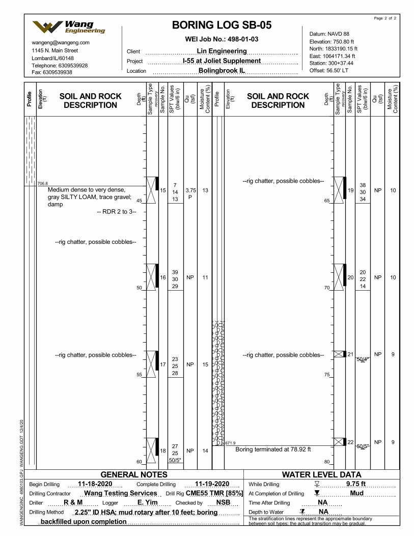
3.75P
NP
NP
NP
NP
NP
NP
NP
15
16
17
18
19
20
21
22
71413
393029
232528
2725
50/5"
383034
202214
50/4"
50/5"
13
11
15
14
10
10
9
9
706.8
671.9
Medium dense to very dense,gray SILTY LOAM, trace gravel;damp
-- RDR 2 to 3--
--rig chatter, possible cobbles--
--rig chatter, possible cobbles--
--rig chatter, possible cobbles--
--rig chatter, possible cobbles--
Boring terminated at 78.92 ft
45
50
55
60
Pro
file
Fax: 6309539938
(blw
/6 in
)
Offset: 56.50' LT
Ele
vatio
n
11-18-2020WATER LEVEL DATA
reco
very
I-55 at Joliet Supplement
reco
very
Datum: NAVD 88
Sam
ple
Typ
e
(ft)
GENERAL NOTES
WEI Job No.: 498-01-03
BORING LOG SB-05
Logger
R & M NAE. Yim
Page 2 of 2
Qu
Moi
stur
e
At Completion of Drilling Mud
NANSB
Qu
(ft)
(ft)
East: 1064171.34 ft
Drilling Contractor
While Drilling
Station: 300+37.44
Pro
file
Ele
vatio
n
Time After Drilling
9.75 ft
Dep
th
Lombard/IL/60148
Dep
th
Moi
stur
e
(tsf
)
(ft)
Wang Testing Services
Con
tent
(%
)
Client
11-19-2020
Sam
ple
Typ
e
ft
Telephone: 6309539928Location
Checked by
Depth to Water
Sam
ple
No.
Sam
ple
No.
1145 N. Main Street
(tsf
)
Con
tent
(%
)
Lin Engineering
Drilling Method
Driller
Begin Drilling
Pro
file
North: 1833190.15 ft
CME55 TMR [85%]
(blw
/6 in
)
Project
Elevation: 750.80 ftE
leva
tion
SOIL AND ROCKDESCRIPTION
2.25" ID HSA; mud rotary after 10 feet; boringbackfilled upon completion
Bolingbrook IL
Complete Drilling
SOIL AND ROCKDESCRIPTION
Drill Rig
The stratification lines represent the approximate boundarybetween soil types; the actual transition may be gradual.
SP
T V
alue
s
SP
T V
alue
s
WA
NG
EN
GIN
C 4
9801
03.G
PJ
WA
NG
EN
G.G
DT
12/
4/2
0
65
70
75
80

6.48B
3.85B
4.59B
3.69B
2.25P
3.00P
3.20B
3.00P
4.67B
5.17B
2.71B
2.21B
NP
NP
1
2
3
4
5
6
7
8
9
10
11
12
13
14
957
569
569
569
448
467
14810
577
569
81113
438
568
141617
322931
13
15
17
13
16
14
15
14
16
16
16
17
9
9
732.1
731.6
728.3
723.3
722.5
706.8
706.0
701.3
11-inch thick CONCRETE--PAVEMENT--
Gray SANDY GRAVEL; damp--AGGREGATE BASE--
Very stiff to hard, gray SILTYCLAY, trace gravel
--FILL----RDR 2 to 3--
Very stiff to hard, gray SILTYCLAY, trace gravel
--RDR 2 to 3--
Gray SILTY LOAM, trace gravel;wet to saturated
--RDR 2--
Very stiff to hard, gray SILTYCLAY, trace gravel
--RDR 2--
--LL(%)=30, PL(%)=15----%Gravel=3.3----%Sand=9.9----%Silt=58.6--
--%Clay=28.3--
Medium dense, gray SILTYLOAM, trace gravel; moist
Very stiff, gray SILTY CLAY,trace gravel
--RDR 2--
Dense to very dense, gray SILTYLOAM, trace gravel; damp
--RDR 2 to 4--
--rig chatter, possible cobbles--
5
10
15
20
Pro
file
Fax: 6309539938
(blw
/6 in
)
Offset: 78.35' LT
Ele
vatio
n
11-19-2020WATER LEVEL DATA
reco
very
I-55 at Joliet Supplement
reco
very
Datum: NAVD 88
Sam
ple
Typ
e
(ft)
GENERAL NOTES
WEI Job No.: 498-01-03
BORING LOG SB-06
Logger
R & M NAE. Yim
Page 1 of 2
Qu
Moi
stur
e
At Completion of Drilling DRY
NANSB
Qu
(ft)
(ft)
East: 1064292.65 ft
Drilling Contractor
While Drilling
Station: 302+00.28
Pro
file
Ele
vatio
n
Time After Drilling
9.75 ft
Dep
th
Lombard/IL/60148
Dep
th
Moi
stur
e
(tsf
)
(ft)
Wang Testing Services
Con
tent
(%
)
Client
11-20-2020
Sam
ple
Typ
e
ft
Telephone: 6309539928Location
Checked by
Depth to Water
Sam
ple
No.
Sam
ple
No.
1145 N. Main Street
(tsf
)
Con
tent
(%
)
Lin Engineering
Drilling Method
Driller
Begin Drilling
Pro
file
North: 1833300.96 ft
CME55 TMR [85%]
(blw
/6 in
)
Project
Elevation: 733.04 ftE
leva
tion
SOIL AND ROCKDESCRIPTION
2.25" ID HSA; boring backfilled upon completion
Bolingbrook IL
Complete Drilling
SOIL AND ROCKDESCRIPTION
Drill Rig
The stratification lines represent the approximate boundarybetween soil types; the actual transition may be gradual.
SP
T V
alue
s
SP
T V
alue
s
WA
NG
EN
GIN
C 4
9801
03.G
PJ
WA
NG
EN
G.G
DT
12/
4/2
0
25
30
35
40

NP
NP
NP
NP
15
16
17
18
302221
1920
50/5"
394646
55
8
17
8
8674.0
--rig chatter, possible cobbles--
--hard drilling, rig chatter,possible cobbles--
--hard drilling, rig chatter,possible cobbles--
--hard drilling, rig chatter,possible cobbles--
Boring terminated at 59.00 ft
45
50
55
60
Pro
file
Fax: 6309539938
(blw
/6 in
)
Offset: 78.35' LT
Ele
vatio
n
11-19-2020WATER LEVEL DATA
reco
very
I-55 at Joliet Supplement
reco
very
Datum: NAVD 88
Sam
ple
Typ
e
(ft)
GENERAL NOTES
WEI Job No.: 498-01-03
BORING LOG SB-06
Logger
R & M NAE. Yim
Page 2 of 2
Qu
Moi
stur
e
At Completion of Drilling DRY
NANSB
Qu
(ft)
(ft)
East: 1064292.65 ft
Drilling Contractor
While Drilling
Station: 302+00.28
Pro
file
Ele
vatio
n
Time After Drilling
9.75 ft
Dep
th
Lombard/IL/60148
Dep
th
Moi
stur
e
(tsf
)
(ft)
Wang Testing Services
Con
tent
(%
)
Client
11-20-2020
Sam
ple
Typ
e
ft
Telephone: 6309539928Location
Checked by
Depth to Water
Sam
ple
No.
Sam
ple
No.
1145 N. Main Street
(tsf
)
Con
tent
(%
)
Lin Engineering
Drilling Method
Driller
Begin Drilling
Pro
file
North: 1833300.96 ft
CME55 TMR [85%]
(blw
/6 in
)
Project
Elevation: 733.04 ftE
leva
tion
SOIL AND ROCKDESCRIPTION
2.25" ID HSA; boring backfilled upon completion
Bolingbrook IL
Complete Drilling
SOIL AND ROCKDESCRIPTION
Drill Rig
The stratification lines represent the approximate boundarybetween soil types; the actual transition may be gradual.
SP
T V
alue
s
SP
T V
alue
s
WA
NG
EN
GIN
C 4
9801
03.G
PJ
WA
NG
EN
G.G
DT
12/
4/2
0

NP
NP
2.71B
2.00P
1.25P
3.61B
3.77B
2.13B
NR
3.53B
4.18B
NA
NP
NP
1
2
3
4
5
6
7
8
9
10
11
12
13
14
101011
858
459
7911
435
6816
5813
5611
71113
6714
5713
6816
263229
313233
5
16
21
17
15
15
18
21
16
17
11
12
732.7
728.1
723.1
721.6701.9
11-inch thick CONCRETE--PAVEMENT--
Medium dense, gray SANDYGRAVEL; damp
--AGGREGATE BASE---- RDR 2--
Very stiff, gray SILTY CLAY,trace gravel
--RDR 2--
Gray SILTY LOAM; moist
Very stiff to hard, gray SILTYCLAY, trace gravel
--RDR 2--
Dense to very dense, gray SILTYLOAM, trace gravel; damp
--RDR 3 to 4--
5
10
15
20
Pro
file
Fax: 6309539938
(blw
/6 in
)
Offset: 87.92' LT
Ele
vatio
n
11-17-2020WATER LEVEL DATA
reco
very
I-55 at Joliet Supplement
reco
very
Datum: NAVD 88
Sam
ple
Typ
e
(ft)
GENERAL NOTES
WEI Job No.: 498-01-03
BORING LOG SB-07
Logger
R & M NAE. Yim
Page 1 of 2
Qu
Moi
stur
e
At Completion of Drilling Mud
NANSB
Qu
(ft)
(ft)
East: 1064317.19 ft
Drilling Contractor
While Drilling
Station: 302+36.81
Pro
file
Ele
vatio
n
Time After Drilling
3.50 ft
Dep
th
Lombard/IL/60148
Dep
th
Moi
stur
e
(tsf
)
(ft)
Wang Testing Services
Con
tent
(%
)
Client
11-18-2020
Sam
ple
Typ
e
ft
Telephone: 6309539928Location
Checked by
Depth to Water
Sam
ple
No.
Sam
ple
No.
1145 N. Main Street
(tsf
)
Con
tent
(%
)
Lin Engineering
Drilling Method
Driller
Begin Drilling
Pro
file
North: 1833329.65 ft
CME55 TMR [85%]
(blw
/6 in
)
Project
Elevation: 733.62 ftE
leva
tion
SOIL AND ROCKDESCRIPTION
2.25" ID HSA; mud rotary after 10 feet; boringbackfilled upon completion
Bolingbrook IL
Complete Drilling
SOIL AND ROCKDESCRIPTION
Drill Rig
The stratification lines represent the approximate boundarybetween soil types; the actual transition may be gradual.
SP
T V
alue
s
SP
T V
alue
s
WA
NG
EN
GIN
C 4
9801
03.G
PJ
WA
NG
EN
G.G
DT
12/
4/2
0
25
30
35
40

NP
NP
NP
NP
15
16
17
18
292523
111320
3045
50/6"
3837
50/5"
10
18
8
9
673.7
--rig chatter, possible cobbles--
--rig chatter, possible cobbles--
--rig chatter, possible cobbles--
--rig chatter, possible cobbles--
Boring terminated at 59.91 ft
45
50
55
60
Pro
file
Fax: 6309539938
(blw
/6 in
)
Offset: 87.92' LT
Ele
vatio
n
11-17-2020WATER LEVEL DATA
reco
very
I-55 at Joliet Supplement
reco
very
Datum: NAVD 88
Sam
ple
Typ
e
(ft)
GENERAL NOTES
WEI Job No.: 498-01-03
BORING LOG SB-07
Logger
R & M NAE. Yim
Page 2 of 2
Qu
Moi
stur
e
At Completion of Drilling Mud
NANSB
Qu
(ft)
(ft)
East: 1064317.19 ft
Drilling Contractor
While Drilling
Station: 302+36.81
Pro
file
Ele
vatio
n
Time After Drilling
3.50 ft
Dep
th
Lombard/IL/60148
Dep
th
Moi
stur
e
(tsf
)
(ft)
Wang Testing Services
Con
tent
(%
)
Client
11-18-2020
Sam
ple
Typ
e
ft
Telephone: 6309539928Location
Checked by
Depth to Water
Sam
ple
No.
Sam
ple
No.
1145 N. Main Street
(tsf
)
Con
tent
(%
)
Lin Engineering
Drilling Method
Driller
Begin Drilling
Pro
file
North: 1833329.65 ft
CME55 TMR [85%]
(blw
/6 in
)
Project
Elevation: 733.62 ftE
leva
tion
SOIL AND ROCKDESCRIPTION
2.25" ID HSA; mud rotary after 10 feet; boringbackfilled upon completion
Bolingbrook IL
Complete Drilling
SOIL AND ROCKDESCRIPTION
Drill Rig
The stratification lines represent the approximate boundarybetween soil types; the actual transition may be gradual.
SP
T V
alue
s
SP
T V
alue
s
WA
NG
EN
GIN
C 4
9801
03.G
PJ
WA
NG
EN
G.G
DT
12/
4/2
0

NP
1.72B
1.00P
3.28B
2.05B
1.50P
1.80B
NR
2.05B
1.97B
4.25P
4.35B
NA
2.13B
1
2
3
4
5
6
7
8
9
10
11
12
13
14
964
445
224
479
345
456
335
5715
457
161915
91315
91618
81112
81014
5
25
23
19
18
15
17
20
18
19
17
19
17
752.3
750.3
749.6
743.8
742.8
12-inch thick ASPHALT--SHOULDER PAVEMENT--
Medium dense, gray SANDYGRAVEL; damp
--AGGREGATE BASE--
Very stiff, black SILTY CLAY--FILL--
--RDR 2 to 3--
Stiff to very stiff, brown and graySILTY CLAY to SILTY CLAYLOAM
--RDR 2----LL(%)=33, PL(%)=16--
--%Gravel=0.0----%Sand=6.6----%Silt=71.8--
--%Clay=21.6--
Brown SILTY LOAM; damp tomoist
--RDR 2--
Stiff to hard, gray SILTY CLAY,trace to some gravel
--RDR 2 to 3--
-rig chatter, possible cobbles--
5
10
15
20
Pro
file
Fax: 6309539938
(blw
/6 in
)
Offset: 60.59' LT
Ele
vatio
n
11-16-2020WATER LEVEL DATA
reco
very
I-55 at Joliet Supplement
reco
very
Datum: NAVD 88
Sam
ple
Typ
e
(ft)
GENERAL NOTES
WEI Job No.: 498-01-03
BORING LOG SB-08
Logger
R & G NAE. Yim
Page 1 of 2
Qu
Moi
stur
e
At Completion of Drilling Mud
NANSB
Qu
(ft)
(ft)
East: 1064410.74 ft
Drilling Contractor
While Drilling
Station: 303+31.71
Pro
file
Ele
vatio
n
Time After Drilling
DRY
Dep
th
Lombard/IL/60148
Dep
th
Moi
stur
e
(tsf
)
(ft)
Wang Testing Services
Con
tent
(%
)
Client
11-16-2020
Sam
ple
Typ
e
ft
Telephone: 6309539928Location
Checked by
Depth to Water
Sam
ple
No.
Sam
ple
No.
1145 N. Main Street
(tsf
)
Con
tent
(%
)
Lin Engineering
Drilling Method
Driller
Begin Drilling
Pro
file
North: 1833361.31 ft
CME55 TMR [85%]
(blw
/6 in
)
Project
Elevation: 753.33 ftE
leva
tion
SOIL AND ROCKDESCRIPTION
2.25" ID HSA; mud rotary after 10 feet; boringbackfilled upon completion
Bolingbrook IL
Complete Drilling
SOIL AND ROCKDESCRIPTION
Drill Rig
The stratification lines represent the approximate boundarybetween soil types; the actual transition may be gradual.
SP
T V
alue
s
SP
T V
alue
s
WA
NG
EN
GIN
C 4
9801
03.G
PJ
WA
NG
EN
G.G
DT
12/
4/2
0
25
30
35
40

2.00P
1.80B
1.50P
1.00P
3.00P
3.00P
2.50P
NP
15
16
17
18
19
20
21
22
181619
81012
123544
212328
252316
2340
50/4"
3450/3"
50/6"
16
17
13
16
14
10
9
9
699.3
674.3
-rig chatter, possible cobbles--
Dense to very dense, gray SILTto SILTY LOAM, trace gravel;damp to moist
--RDR 2 to 4--
-rig chatter, possible cobbles--
--sand seams, wet--
-hard drilling, rig chatter, possiblecobbles--
Boring terminated at 79.00 ft
45
50
55
60
Pro
file
Fax: 6309539938
(blw
/6 in
)
Offset: 60.59' LT
Ele
vatio
n
11-16-2020WATER LEVEL DATA
reco
very
I-55 at Joliet Supplement
reco
very
Datum: NAVD 88
Sam
ple
Typ
e
(ft)
GENERAL NOTES
WEI Job No.: 498-01-03
BORING LOG SB-08
Logger
R & G NAE. Yim
Page 2 of 2
Qu
Moi
stur
e
At Completion of Drilling Mud
NANSB
Qu
(ft)
(ft)
East: 1064410.74 ft
Drilling Contractor
While Drilling
Station: 303+31.71
Pro
file
Ele
vatio
n
Time After Drilling
DRY
Dep
th
Lombard/IL/60148
Dep
th
Moi
stur
e
(tsf
)
(ft)
Wang Testing Services
Con
tent
(%
)
Client
11-16-2020
Sam
ple
Typ
e
ft
Telephone: 6309539928Location
Checked by
Depth to Water
Sam
ple
No.
Sam
ple
No.
1145 N. Main Street
(tsf
)
Con
tent
(%
)
Lin Engineering
Drilling Method
Driller
Begin Drilling
Pro
file
North: 1833361.31 ft
CME55 TMR [85%]
(blw
/6 in
)
Project
Elevation: 753.33 ftE
leva
tion
SOIL AND ROCKDESCRIPTION
2.25" ID HSA; mud rotary after 10 feet; boringbackfilled upon completion
Bolingbrook IL
Complete Drilling
SOIL AND ROCKDESCRIPTION
Drill Rig
The stratification lines represent the approximate boundarybetween soil types; the actual transition may be gradual.
SP
T V
alue
s
SP
T V
alue
s
WA
NG
EN
GIN
C 4
9801
03.G
PJ
WA
NG
EN
G.G
DT
12/
4/2
0
65
70
75
80

1145 North Main Street Lombard, Illinois 60148
Phone (630) 953-9928 www.wangeng.com
Geotechnical • Construction • Environmental Quality Engineering Services Since 1982
APPENDIX B

0
5
10
15
20
25
30
35
40
45
50
55
60
65
70
75
80
85
90
95
100
0.0010.010.1110100
60
fine
HYDROMETERU.S. SIEVE OPENING IN INCHES U.S. SIEVE NUMBERS
3121111
15161516
18282627
27.310.710.812.1
PE
RC
EN
T FI
NE
R B
Y W
EIG
HT
SILT AND CLAY
1.12
13.5 ft
11.0 ft
13.0 ft
21.0 ft
GRAIN SIZE IN MILLIMETERS
2006
coarseGRAVEL
Silty Loam Silty Clay Loam Silty Clay Loam Silty Clay Loam
13.32.93.47.3
49.562.263.956.6
9.924.321.924.0
IDH ClassificationSB-01#6
SB-02#5
SB-03#
SB-04#9
13.5 ft
11.0 ft
13.0 ft
21.0 ft
SB-01#6
SB-02#5
SB-03#
SB-04#9
6 810 14
Specimen Identification
Specimen Identification199.59.512.5
0.002
16 20 30 40 501.5 1/23/8 3
%Gravel %Sand %Silt %Clay
100 1403 2
COBBLES
4
LL PL38.16
D10
SAND
41 3/4
CuPI Cc
GRAIN SIZE DISTRIBUTION
D100 D60 D300.080.0150.0160.013
0.0140.0030.0040.003
Wang Engineering, Inc.1145 N Main StreetLombard, IL 60148Telephone: 630 953-9928Fax: 630 953-9938
Project: I-55 Bridge over Joliet Road
Location: Will County, Illinois
Number: 498-01-01
WE
I_G
RA
IN_S
IZE
_ID
H 4
9801
01.G
PJ
US
_LA
B.G
DT
5/7
/20

0
5
10
15
20
25
30
35
40
45
50
55
60
65
70
75
80
85
90
95
100
0.0010.010.1110100
60
fine
HYDROMETERU.S. SIEVE OPENING IN INCHES U.S. SIEVE NUMBERS
15
17
15
16
30
33
9.9
6.6
PE
RC
EN
T F
INE
R B
Y W
EIG
HT
SILT AND CLAY
16.0 ft
6.0 ft
GRAIN SIZE IN MILLIMETERS
2006
coarseGRAVEL
Silty Clay Loam
Silty Clay Loam
3.3
0.0
58.6
71.8
28.3
21.6
IDH ClassificationSB-06#7
SB-08#3
16.0 ft
6.0 ft
SB-06#7
SB-08#3
6 810 14
Specimen Identification
Specimen Identification
12.5
2
16 20 30 40 501.5 1/23/8 3
%Gravel %Sand %Silt %Clay
100 1403 2
COBBLES
4
LL PL
D10
SAND
41 3/4
CuPI Cc
GRAIN SIZE DISTRIBUTION
D100 D60 D30
0.011
0.024
0.002
0.005
Wang Engineering, Inc.1145 N. Main StreetLombard/IL/60148Telephone: 6309539928Fax: 6309539938
Project: I-55 at Joliet Supplement
Location: Bolingbrook IL
Number: 498-01-03
WE
I_G
RA
IN_S
IZE
_ID
H 4
9801
03.G
PJ
US
_LA
B.G
DT
12/
2/2
0

0
10
20
30
40
50
60
0 20 40 60 80 100
ML
CL
MH
CH
59
87
86
81
18
28
26
27
15
16
15
16
3
12
11
11
LL PL PI
ATTERBERG LIMITS' RESULTS
Specimen Identification Fines
CL-ML
PLASTICITY
INDEX
LIQUID LIMIT
Silty Loam
Silty Clay Loam
Silty Clay Loam
Silty Clay Loam
IDH Classification
SB-01#6
SB-02#5
SB-03#
SB-04#9
13.5 ft
11.0 ft
13.0 ft
21.0 ft
Wang Engineering, Inc.1145 N Main StreetLombard, IL 60148Telephone: 630 953-9928Fax: 630 953-9938
Project: I-55 Bridge over Joliet Road
Location: Will County, Illinois
Number: 498-01-01
WE
I_A
TTE
RB
ER
G_L
IMIT
S ID
H 4
9801
01.G
PJ
US
_LA
B.G
DT
5/7
/20
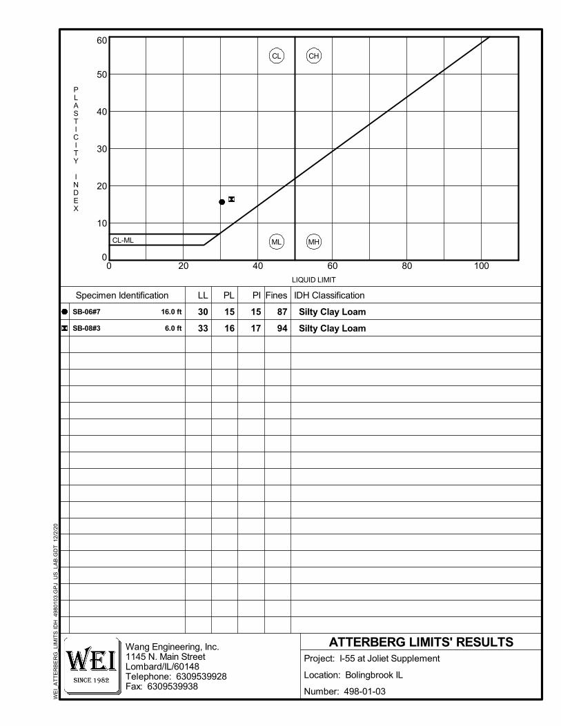
0
10
20
30
40
50
60
0 20 40 60 80 100
ML
CL
MH
CH
87
94
30
33
15
16
15
17
LL PL PI
ATTERBERG LIMITS' RESULTS
Specimen Identification Fines
CL-ML
PLASTICITY
INDEX
LIQUID LIMIT
Silty Clay Loam
Silty Clay Loam
IDH Classification
SB-06#7
SB-08#3
16.0 ft
6.0 ft
Wang Engineering, Inc.1145 N. Main StreetLombard/IL/60148Telephone: 6309539928Fax: 6309539938
Project: I-55 at Joliet Supplement
Location: Bolingbrook IL
Number: 498-01-03
WE
I_A
TT
ER
BE
RG
_LIM
ITS
IDH
498
010
3.G
PJ
US
_LA
B.G
DT
12/
2/2
0

1145 North Main Street Lombard, Illinois 60148
Phone (630) 953-9928 www.wangeng.com
Geotechnical • Construction • Environmental Quality Engineering Services Since 1982
APPENDIX C

LayerID
Total Unit Weight
(pcf)
UndrainedCohesion
(psf)
UndrainedFriction Angle
(degrees)
12345
125115120120120
10000
150017003200
030000
Description
Embankment FillM Dense SA Gravel Fill
Stiff Clay Loam FillStiff to V Stiff SI CL to SI CL LoamStiff to Hard SI CL to SI CL Loam
Undrained Analysis, SN. 099-0028 , Sta. 301+00.00, Ref Boring: SB-04
1:2 (V:H)
DRAWN BY: RKC
CHECKED BY: A. KurniaSCALE: GRAPHICAL APPENDIX C-1
FOR LIN ENGINEERING, LTD. 498-01-01
GLOBAL STABILITY ANALYSIS: INTERSTATE 55 BRIDGE OVER JOLIET ROAD, SN. 099-0028, WILL COUNTY, ILLINOIS
1145 N. Main StreetLombard, IL 60148www.wangeng.com
I-55(EL 751.6 feet)
M Dense SA Gravel Fill
Stiff SI CL Loam
V Stiff SI Clay
M Dense to V Dense SA Gravel
Soft to M Stiff SI Clay
M Dense GR Sand
Embankment Fill
Traffic Load 250 psf
FILL
FILL
Stiff Clay Loam Fill
Stiff to V Stiff SI CL to SI CL Loam
Stiff to Hard SI CL to SI CL Loam
(EL 745.7 feet)
9.27

LayerID
Total Unit Weight
(pcf)
DrainedCohesion
(psf)
DrainedFriction Angle
(degrees)
12345
125115120120120
1000
100100100
3030313232
Description
Embankment FillM Dense SA Gravel Fill
Stiff Clay Loam FillStiff to V Stiff SI CL to SI CL LoamStiff to Hard SI CL to SI CL Loam
Drained Analysis, SN. 099-0028 , Sta. 301+00.00, Ref Boring: SB-04
1:2 (V:H)
DRAWN BY: RKC
CHECKED BY: A. KurniaSCALE: GRAPHICAL APPENDIX C-2
FOR LIN ENGINEERING, LTD. 498-01-01
GLOBAL STABILITY ANALYSIS:INTERSTATE 55 BRIDGE OVER JOLIETROAD, SN. 099-0028, WILL COUNTY, ILLINOIS
1145 N. Main StreetLombard, IL 60148www.wangeng.com
I-55(EL 751.6 feet)
M Dense SA Gravel Fill
Stiff SI CL Loam
V Stiff SI Clay
M Dense to V Dense SA Gravel
Soft to M Stiff SI Clay
M Dense GR Sand
Embankment Fill
Traffic Load 250 psf
FILL
FILL
Stiff Clay Loam Fill
Stiff to V Stiff SI CL to SI CL Loam
Stiff to Hard SI CL to SI CL Loam
(EL 745.7 feet)
3.34

1145 North Main Street Lombard, Illinois 60148
Phone (630) 953-9928 www.wangeng.com
Geotechnical • Construction • Environmental Quality Engineering Services Since 1982
APPENDIX D

Specifications, Customary U.S. Units, 9th Edition
2020 AASHTO LRFD Bridge Design
fy = 50,000 psi (M270 Grade 50)
fy = 60,000 psi (Reinforcement)
f'c = 4,000 psi (Superstructure)
f'c = 3,500 psi (Substructure)
D1
DS
New Construction:
LOADING HL-93
DESIGN SPECIFICATIONS
DESIGN STRESSES
SEISMIC DATA
NOTES:
New Construction:
FIELD UNITS (New Construction)
E
Tw
p.
37
NN 11 12
14 13
LOCATION SKETCH
4'-0''
Range 10E Of The 3 P.M.
I-55
Joliet
Road
I-55
PLAN
EF E
N
4'-0''12'-0''12'-0''4'-0''
ELEVATION
4'-0'' 62'-4" (Span 3)78'-0" (Span 2)62'-4" (Span 1)
61'-
6''
1'-
5''
1'-
5"
Lanes
24'-0''
Shld.
4'-0''
Shld.
4'-0''
SCOPE OF WORK HIGHWAY CLASSIFICATION
Elev. 750.35
Sta. 299+84.29
Bk. W. Abut.
El. 750.38
Sta. 299+88.29
¡ Brg. W. Abut.
Increase
Stations
Increase
Stations
El. 750.61
Sta. 300+21.44
¡ Pier 1
El. 750.88
Sta. 300+50.61
¡ Pier 1
El. 751.50
Sta. 301+28.61
¡ Pier 2
El. 750.10
Sta. 299+59.11
¡ Brg. S. Abut.
Elev. 750.09
Sta. 299+55.11
Bk. S. Abut.
El. 752.00
Sta. 301+90.95
¡ Brg. N. Abut.
1 3
Sta. 14+33.85 (Joliet Rd.)
Sta. 300+49.14 (F.A.I. I-55)
Sta. 14+17.20 (Joliet Rd.)
Sta. 300+63.71 (SB PGL)
Sta. 14+50.49 (Joliet Rd.)
Sta. 300+34.56 (NB PGL)
Slab (Typ.)
Approach
30' Bridge
Sta. 299+58.92
Light Pole
Sta. 301+90.01
Light Pole
GENERAL PLAN
to out bridge width varies from 119'-2 7/8" to 123-6 18". Traffic shall be maintained utilizing stage construction.
The structure is skewed 61*08' left advanced. The overall length measures 210'-8" back to back of abutment with an out
on concrete piles. the Piers are multi-column piers rectangular concrete pier substructure units on spread footings.
structure is comprised of a three span, non-composite, continuous 36" steel wide flange beams on stub abutments founded
US66A (North Ramp), Section 29R1-HB, at Station 684+80.6. Structure was widened in 1976 and 1987. The existing
Existing Structures: Structure Number 099-0028 was originally constructed in 1955 as IN 187(5), FA Rt.34 (US 66) over
No Salvage
£ Joliet Rd.
NB I-55 P.G.
SB I-55 P.G.
P.G.
Joliet Rd. P.G.
Type 6B Std. 631033 (typ.)
Traffic Barrier Terminal
1.5%1.5%
F.A.I. RTE. 55 (I-55)
F.A.U. RTE 378 (JOLIET RD)
" N.
Abut.
21
14'-
10
10'-
8"
S.
Abut.
Shldr
''2
16'-
7
Shldr
''2
16'-
7
1'-
5''
SB-01
SB-03SB-04
SB-02
Elev. ± 725.1
Elev. ± 743.4Elev. ± 741.5*
*
*At rt. L's to Skew
vertical clearance
Point of minimum
Elev. 752.03
Sta. 301+94.95
Bk. N. Abut.
Elev. 751.72
Sta. 301+65.77
Bk. E. Abut.
El. 751.69
Sta. 301+61.77
¡ Brg. E. Abut.
El. 751.21
Sta. 300+99.44
¡ Pier 2
Line, typ.
Existing Ground
STRUCTURE NO. SN 099-0028
STATION 300+49.14
WILL COUNTY
F.A.I. RTE. 55 - SEC. (29-R1HP)99R-4
I-55 OVER JOLIET ROAD
GENERAL PLAN & ELEVATION
Two-Way Traffic
Posted Speed: 55 m.p.h.
Design Speed: 60 m.p.h.
DHV: 23,401 (2032)
ADTT:14,816 (2019); 37,440 (2032)
ADT:92,600 (2019); 234,005 (2032)
Functional Class: Interstate
One-Way Traffic
Posted Speed: 45 m.p.h.
Design Speed: 50 m.p.h.
DHV: 1,811 (2032)
ADTT:6,195 (2019); 3,802 (2032)
ADT:29,500 (2019); 18,104 (2032)
Functional Class: Arterial
Ramp £
Entrance
¡ F.A.I. 552'-
11"
Vert. Clearance
Minimum 14'-9"
Footing
Spread
All Structural steel shall be hot dipped galvanized.
elevations after grinding.
The profile grade shows the final
bridge deck and the bridge approach slabs.
Up to Ɓ inch may be ground off the
Soil Site Class = C
Design Spectral Acceleration at 0.2 sec. (S ) = 0.122 g
Design Spectral Acceleration at 1.0 sec. (S ) = 0.065 g
Seismic Performance Zone (SPZ) = 1
''2
11'-
5
2'-
11"
210'-8" Bk. to Bk. Abutments
¡ F.A.I. 55
Measured along
**
*
**
**
4.00 %
to be reinstalled on new foundation, typ.
Remove existing Light Pole and Luminaire
25'-0"
permit num
ber allowin
g permanen
t construc
tion as sho
wn in the
contract p
lans.
application
by the Con
tractor sha
ll refer to
the IDNR
3704 Flood
way Constr
uction
the placem
ent of mat
erial for r
un-arounds
, causeways
, etc. Any
permit
constructio
n activity
placed in t
he water e
xcept coff
erdams. Th
is shall in
clude
of Natural
Resources
(IDNR), Off
ice of Wate
r Resource
s for any
temporary
The Cont
ractor sha
ll obtain a
constructi
on permit
from the Il
linois Depa
rtment
Sides, typ.
spacing, Both
DS-11 Scupper
Entrance Ramp
Only.
at West Abut.
Retention System
Temporary Soil
Piling, typ.
Temporary Sheet
Piling, typ.
Temporary Sheet
Type 6B Std. 631033
Traffic Barrier Terminal
Type 6B Std. 631033
Traffic Barrier Terminal
Structure
Proposed
1:2 (V:H) 1:2 (V:H
)
**
Elev. ± 724.9
typ.
10'-0''
typ.
±8'-0"
FIELD UNITS (Existing Construction)
fy = 60,000 psi (Reinforcement)
f'c = 4,000 psi (Substructure)
typ.
Structure
Limits of Existing
1"
Open Jt.
61°08'00"
Elev. 753.835
Bench Mark: BM #3. " " Cut on top at the west end of the northern parapet wall of bridge of I-55 over Joliet Rd.
39'-3" Stage II Const.
Replace bridge deck expansion joints.8.
Remove and replace existing approach slabs.7.
Replace existing bearing with elastomeric.6.
repairs at existing piers.
Construct bearing pedestals and complete substructure5.
Widen existing piers & abutments on NB & SB sides.4.
Joliet Road.
Remove and Replace underpass lighting over existing 3.
accommodate the new bridge width.
Remove and replace existing bridge superstructure to 2.
Widen embankment cone at abutments on NB & SB sides.1.
allow for 25#/sf future wearing surface.
Proposed superstructure was designed to
the capacity of the original (1955) substructure.
No future wearing surface will be allowed due to
"2
172'-
1
See Roadway Plans for Traffic Control
Shell Piles typ.
Piles and New Metal
Existing Concrete
43' Stage 1 Const.
Const.
51'-4 1/2" Stage III
NB Lanes
36'-
0''
Shld.
16'
SB Lanes
36'-
0''
15'-
11 1/2" to 11'-
9"
Shld.
Varie
s
(Composite full length)
W36
115+00
15+
00
300+00
PI Sta 111
+19.5
2
PI Sta 115
+38.2
2
6"
SECTION COUNTY
ILLINOIS FED. AID PROJECT
55
TOTAL
SHEETS
SHEET
NO.RTE.
(29-R1HB)99R-4
CONTRACT NO. 62H03DEPARTMENT OF TRANSPORTATION
STATE OF ILLINOIS
USER NAME =
PLOT SCALE =
PLOT DATE =
DESIGNED REVISED
REVISED
REVISED
REVISED
F.A.I.
WILL
SHEET OF XX SHEETS
-
-
-
-
-
-
-
-
KGW
HA
WAR
JAZ
CHECKED
DRAWN
CHECKED
$TIME$$DATE$
MO
DE
L:
FIL
E N
AM
E:
$M
OD
EL
NA
ME$
$FIL
EL$
Chicago, Illinois 60631; (773) 399-0112
8501 W. Higgins Road; Suite 280 SN 099-0028
Do Not M
ove