Machine Learning and Grammar Induction - CSC2540S Machine ...

454
1
Abstract — In recent years the analysis and estimation of noise
and vibration have been gaining interest. Both, noise and vibra-
tion are often due to the electromagnetic forces in electric ma-
chinery such as induction machines with squirrel-cage rotors.
Manufacturing tolerances and faults have great impact to the
electromagnetic behaviour of electric machines. Therefore, many
studies have been presented concerning the analysis of noise and
vibration in electric machinery. Here, a major task, the eccentric
rotor movement, is studied, applying the finite-element method
and analytical models for the structure-dynamic analysis of an
induction machine with squirrel cage rotor.
Index Terms — FEM, induction machine, acoustics, eccentric
rotor movement, structure dynamics, vibrations.
I. INTRODUCTION
ANY studies have been presented concerning the elec-
tromagnetic and structure dynamic behaviour of Induc-
tion Machines with squirrel-cage rotor (IM) with eccentric
rotor movement [1-4]. The latter usually do not consider any
simulation results which allow the de-coupling of the impact of
eccentric rotor movement from other effects. This might be
due to the high computational costs or a lack of software tools.
Here, exactly this is presented applying the Finite-Element
Method (FEM) and the analytic model of [1,2].
Eccentric rotor movement of electrical machines causes ex-
tra disturbing noise and vibrations. This extra noise can either
occur in terms of additional electromagnetic force harmonics
or in terms of an amplification of harmonics stemming from
the fundamental or saturational fields. The detection of addi-
tional harmonics allows for a detailed analysis of the IM’s
acoustics in both analytical models and measurements [1,3,4].
The impact of the amplification is rather hard to estimate by
measurement and analytic models. Especially in measurements
it is nearly impossible to assure that the reference machine
does not have any eccentricity. Therefore, the aspect of eccen-
tric rotor movement is studied in detail in this paper by means
of numeric simulation. Numeric models allow for the extrac-
tion of single effects and preparation of ideal reference mod-
els.
Next to centric there are two different types of eccentric ro-
tor movements, as Fig. 1 resumes:
1. dynamic eccentricity and
2. static eccentricity.
In the centric case the rotor, stator, and rotational axis lie in
the same location. For the case of dynamic eccentricity the
Manuscript received July 15th, 2006.
C. Schlensok, D. van Riesen, and K. Hameyer are with the Institute
of Electrical Machines, RWTH Aachen University, D-52056 Aachen,
Germany. (phone: +49-241-8097667; fax: +49-241-8092270; e-mail:
Christoph.Schlensok@ iem.rwth-aachen.de).
rotor axis is shifted to one side. The rotational axis remains in
the same location as the stator axis. This way the rotor per-
forms a whiling motion. Finally, the static eccentricity results
in the shifting of both rotor and rotational axis. The rotor
keeps rotating stationary.
Fig. 2 shows the flowchart of the entire structure-dynamic
simulation chain. At first an electromagnetic model is prepared
considering the non-linear behaviour of the iron laminations,
the rotor movement, and the stator currents. Here, the models
are adapted depending on the type of eccentricity simulated.
Four different models are studied:
1. centric model without eccentricity,
2. dynamic eccentric model,
3. static eccentric model, and
4. a combined static-dynamic eccentric model with 50 %
of each type of eccentricity.
The Finite-Element Method (FEM) [5,6] is applied for both
the electromagnetic using the multi-slice method and the struc-
ture-dynamic simulation [9-11].
Structure-Dynamic Analysis of an Induction
Machine with Eccentric Rotor Movement C. Schlensok, D. van Riesen, and K. Hameyer
M
Fig. 1. Types of eccentric rotor movement.
Fig. 2. Flow chart of the structure-dynamic simulation-chain.
454
2
II. ELECTROMAGNETIC SIMULATION
The electromagnetic FE-models consist of stator and rotor
including the 3-phase, 2-layer winding of the stator and the
aluminium-cast rotor-bars. Between stator and rotor the air gap
is located. This is modelled as well. The flux has to cross over.
For numeric and modelling reasons (i.e. the rotational move-
ment) a 3-layer air-gap is constructed. Fig. 6 shows a zoom of
the air gap region with meshed air-gap layers. The central
layer marked with lC is used for re-meshing while applying the
moving-band method [7]. The outer layer lS is connected to the
stator, and the inner layer lR is fixed to the rotor and is rotated
in every time step together with the rotor. Hence, dynamic
eccentric rotor movement results in an eccentric rotor air-gap
layer (Fig. 4) and the static eccentricity in an eccentric stator
air-gap region (Fig. 5)). A combined eccentric model of course
has both an eccentric stator and an eccentric rotor air-gap
layer. For the centric reference model three concentric air-gap
layers are modelled.
The two types of eccentric rotor movement are described in
The electromagnetic simulation provides the magnetic flux-
density distribution for each of the N = 4200 performed simu-
lation- time steps. With this the torque T, net force F, and the
surface-force density σ are calculated. The analysis of T, F,
and σ in the case of eccentric rotor movement is described in
[8]. The torque hardly shows any impact by the eccentricity.
Nevertheless, the net force is affected seriously. Eccentricity
results in very high net-force magnitudes acting onto the bear-
ings. For the studied IM the maximum forces reached for dy-
namic eccentricity exceed the mechanical forces of an unbal-
anced rotor at the same rotor speed by far.
The time-dependent behaviour of the surface-force density
for a single element on the up-running edge of a stator tooth is
shown in Fig. 6. The force pulsates depending on the speed n,
the number of rotor slots NR, the stator frequency f1, and the
number of pole pairs p.
For the structure-dynamic analysis σ is transformed into the
frequency domain (Fig. 7). With the resulting spectrum and the
analytic model of [1] a set of frequencies is selected. All of
them are not special to the effect of eccentricity, since the am-
plification effect of the harmonics is studied explicitly, here.
Additional frequencies resulting from eccentricity are not stud-
ied in the first step. Table I lists the selected frequencies.
Fig. 3. Zoom of air-gap region of the centric electromagnetic FE-model.
Fig. 4. Zoom of air-gap region of dynamic eccentric FE-model.
Fig. 5. Zoom of air-gap region of static eccentric FE-model.
Fig. 6. Time-dependent behavior of the surface-force density.
454
3
Table. I. Selected frequencies from the surface-force density-spectrum.
f [Hz] 98 422 520 618
f [Hz] 716 942 1040 1138
III. STRUCTURE-DYNAMIC SIMULATION
The structure-dynamic simulation is performed for all four
different force excitations resulting from the electromagnetic
models. The mechanical simulation provides the deformation
for all nodes of the structure-dynamic model. The structure-
dynamic FE-model depicted in Fig. 7 consists of all mechani-
cal parts such as stator with winding, rotor with short-circuit
rings, shaft, bearings, end shields with rubber rings, and the
housing which is coupled to the stator with six spiral-steel
springs. The surface-force density of each of the four electro-
magnetic models is transformed to the stator teeth of the me-
chanical model in the frequency domain for the set of selected
frequencies.
The deformation is simulated with linear material behav-
iour. Therefore, complex values can be applied. An example
for the deformation of the IM is shown in Fig. 8. Here, the
deformation of housing and stator is depicted for one single
point in time. As can be seen the magnitudes of the nodal os-
cillations of the stator is significantly higher than for the hous-
ing. This is due to the coupling of stator and housing by spiral-
steel springs reducing the transmitted vibrations.
Since the application of the IM is not in direct influence
range of the human ear, it is of higher interest to study the
body sound which can be transmitted and then be decoupled as
acoustic noise in hearing range [12]. Therefore, the deforma-
tion of the IM is analyzed by three different criteria:
1. the deviation of the deformation between an eccentric
model and the centric reference model,
2. the body-sound level LS along the circumference of the
housing along two lines on both ends of the IM, and
3. the body-sound index LBSI of the housing allowing for
the absolute comparison of the deformation.
Next to these criteria the deformation can be analyzed by
means of the oscillation modes r [1,2]. In the following the
results are discussed in detail.
A. Modes of oscillation
The oscillation modes detected in the simulation model
match the predicted modes from the analytical model of [1].
Fig. 9 shows exemplarily two modes of oscillation which are
due to eccentricity concerning the studied IM. The regarded
frequency is f = 20 Hz which is the rotor speed. For this fre-
Fig. 6. Spectrum of the surface-force density.
Fig. 6. Spectrum of the surface-force density.
Fig. 7. Structure-dynamic FE-model of the induction machine with squirrel-cage rotor.
Fig. 8. Example for the deformation of housing and stator at f = 618 Hz.
454
4
quency the dynamic eccentricity shows the highest impact.
Without any eccentricity there is a very low and insignificant
deformation stated. The static eccentric case shows a slightly
higher deformation with mode number r = 4. For the dynamic
eccentric case the revolving force wave results in an oscillation
mode r = 1 with a very high magnitude. The exaggerated de-
formation in Fig. 9 is 500 times as high for the dynamic case
when compared to the static. This is resumed by Fig. 10. The
deformation is sampled along the outer circumference of the
stator.
B. Deviation of the deformation
In a second step the deviation of the deformation is ana-
lyzed. The deviation is calculated by subtracting the results of
the deformation of the reference model (centric electromag-
netic model) from each of the three eccentric models. By this,
it is possible to detected regions for example of the housing
which are deformed stronger by eccentric rotor movement.
Fig. 11 exemplarily shows the deviation of the deformation
at f = 422 Hz for the three cases. For the dynamic eccentric
case it can be seen the deviation is positive in general. The
dynamic eccentricity results in higher deformation of the stator
and housing for this frequency. The studies have shown that
this is the fact for all selected frequencies. As the plots of the
static and combined eccentric models show static eccentricity
results in a significant increase of the deformation for most of
the housing. Except for the white region opposite of the loca-
tion of the smallest air-gap width the deformation is by far
higher than in the case of a centric or dynamic eccentric rotor
movement.
Next to this, the vibrations of the IM depend in the case of
static eccentricity strongly on the location of the smallest air
Fig. 9. Example for oscillation modes at f = 20 Hz.
Fig. 10. Deformation along outer circumference of stator at f = 20 Hz.
Fig. 11. Deviation of deformation of housing at f = 422 Hz.
dynamic eccentric
static eccentric
static-dynamic
eccentric
454
5
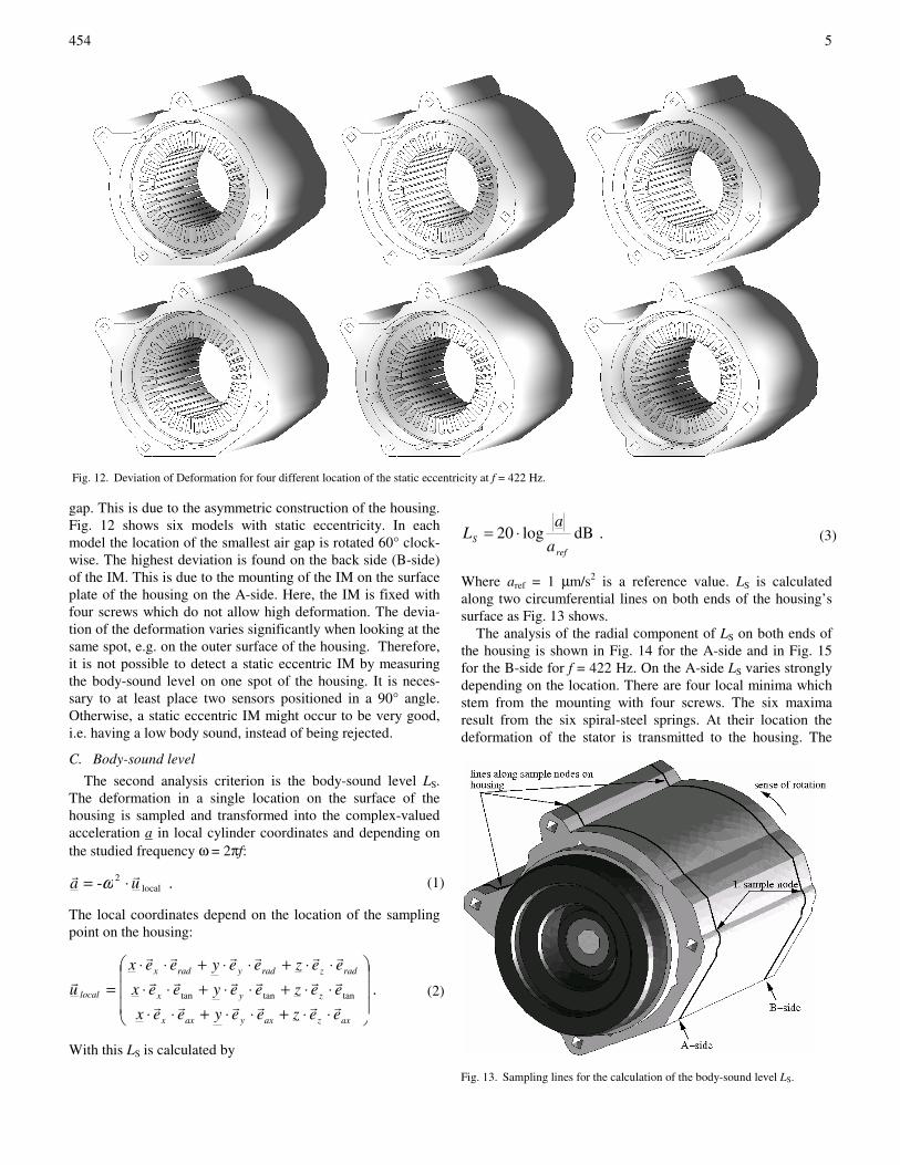
gap. This is due to the asymmetric construction of the housing.
Fig. 12 shows six models with static eccentricity. In each
model the location of the smallest air gap is rotated 60° clock-
wise. The highest deviation is found on the back side (B-side)
of the IM. This is due to the mounting of the IM on the surface
plate of the housing on the A-side. Here, the IM is fixed with
four screws which do not allow high deformation. The devia-
tion of the deformation varies significantly when looking at the
same spot, e.g. on the outer surface of the housing. Therefore,
it is not possible to detect a static eccentric IM by measuring
the body-sound level on one spot of the housing. It is neces-
sary to at least place two sensors positioned in a 90° angle.
Otherwise, a static eccentric IM might occur to be very good,
i.e. having a low body sound, instead of being rejected.
C. Body-sound level
The second analysis criterion is the body-sound level LS.
The deformation in a single location on the surface of the
housing is sampled and transformed into the complex-valued
acceleration a in local cylinder coordinates and depending on
the studied frequency ω = 2πf:
. - local2
uarr
⋅= ω (1)
The local coordinates depend on the location of the sampling
point on the housing:
.tantantan
⋅⋅+⋅⋅+⋅⋅
⋅⋅+⋅⋅+⋅⋅
⋅⋅+⋅⋅+⋅⋅
=
axzaxyaxx
zyx
radzradyradx
local
eezeeyeex
eezeeyeex
eezeeyeex
urrrrrr
rrrrrr
rrrrrr
r
(2)
With this LS is calculated by
. dBlog20ref
Sa
aL ⋅=
(3)
Where aref = 1 µm/s2 is a reference value. LS is calculated
along two circumferential lines on both ends of the housing’s
surface as Fig. 13 shows.
The analysis of the radial component of LS on both ends of
the housing is shown in Fig. 14 for the A-side and in Fig. 15
for the B-side for f = 422 Hz. On the A-side LS varies strongly
depending on the location. There are four local minima which
stem from the mounting with four screws. The six maxima
result from the six spiral-steel springs. At their location the
deformation of the stator is transmitted to the housing. The
Fig. 12. Deviation of Deformation for four different location of the static eccentricity at f = 422 Hz.
Fig. 13. Sampling lines for the calculation of the body-sound level LS.

454
6
centric and dynamic eccentric model result in nearly the same
body-sound level for this frequency. Static eccentricity reaches
the highest values. The combination of both types of eccentric-
ity lies in-between. The position of the smallest and the largest
air gap can be located in the case of static eccentric rotor
movement, coinciding with the highest and the lowest values
of LS.
D. Body-sound index
Finally the body-sound index LBSI representing the entire de-
formation of a body, e.g. the housing, is calculated and ana-
lysed. In the case of dynamic eccentricity the LBSI increases
slightly with the exception of rotor speed f = 20 Hz and the
two highest studied frequencies f = 1040 and 1138 Hz. Here,
LBSI raises significantly. Except for rotor speed static eccentric
rotor movement results in the highest peaks throughout the
spectrum reaching the highest overall value at the first stator-
slot harmonic at f = 720 Hz. The combined eccentric model
shows the high impact of the static eccentricity. Here, the val-
ues are increased very strongly as well.
IV. CONCLUSIONS
The paper presents the structure-dynamic analysis of an in-
duction machine with squirrel-cage rotor (IM) with eccentric
rotor movement. The different types of eccentricity are intro-
duced and their consideration in the electromagnetic Finite-
Element (FE)-models is described. The results of the electro-
magnetic simulation are discussed focussing on the surface-
force density excitation of the stator teeth.
In a second step the mechanical structure-dynamic FE-
model is presented. From the electromagnetic model the sur-
face-force density on the stator teeth is taken as excitation for
the mechanical model. The results of the mechanical simula-
tion are discussed in general and explicitly taking the eccentric
rotor movement into consideration. In general, eccentricity
results in higher deformation of stator and housing of the IM.
Furthermore, it can be stated, that static eccentricity shows the
highest negative impact to the body-sound of the IM also de-
pending on the location of the smallest air gap. This corre-
sponds to measurements.
Applying the 2D-multi-slice technique for the electromag-
netic model allows a fast and accurate analysis of the structure-
dynamic behaviour of an electrical machine, i.e. an IM.
REFERENCES
[1] H. Jordan, Geräuscharme Elektromotoren, Verlag W. Giradet, Essen,
1950.
[2] P. L. Timar, Noise and Vibration of Electrical Machines, Elsevier Sci-
ence Publishing Company, New York, 1998.
[3] A. Tenhunen, T. P. Holopainen, A. Arkkio, “Effects of saturation on the
forces in induction motors with whirling cage rotor,” IEEE Trans. on
Magn., vol 40, no. 2, pp. 766 - 769, March 2004.
[4] J. Rusek, “Diagnostic oriented computer model of the induction ma-
chine, accounting for eccentricities and slotting,” 2nd International
Seminar on Vibrations and Acoustic Noise of Electric Machinery,
VANEM, pp. 75 - 79, September 2000.
[5] O. C. Zienkiewicz, R. L. Taylor, „The finite element method,“
McGraw-Hill Book Company, London, 1989.
[6] A. Kost, “Numerische Methoden in der Berechnung elektromagneti-
scher Felder,” Springer-Verlag, Berlin, Heidelberg, New York, Barce-
lona, Budapest, Hon Kong, London, Mailand, Paris, Santa Clara, Singa-
pore, Tokyo, 2000.
[7] H. De Gersem, J. Gyselinck, P. Dular, K. Hameyer, T. Weiland, „Com-
parison of sliding-surface and moving-band techniques in frequency-
domain finite-element models of rotating machines,“ COMPEL, vol 23,
no. 4, pp. 1006 – 1014, November 2004.
[8] C. Schlensok, G. Henneberger, “Comparison of static, dynamic, and
static-dynamic eccentricity in induction machines with squirrel-cage ro-
tors using 2D-transient FEM,” COMPEL, vol 23, no. 4, pp. 1070 –
1079, November 2004.
[9] D. van Riesen, C. Monzel, C. Kaehler, C. Schlensok, G. Henneberger,
“iMOOSE-an open-source environment for finite-element calculations,”
IEEE Trans. on Magn., vol 40, no. 2, pp. 1390 - 1393, March 2004.
[10] J. P. A. Bastos, N. Sadowski, Electromagnetic modelling by finite ele-
ment methods, Marcel Dekker, Inc., New York, Basel, 2003.
[11] J. J. C. Gyselinck, L. Vandevelde, J. A. A. Melkebeek, “Multi-slice FE
modelling of electrical machines with skewed slots – the skew discreti-
zation error,” IEEE Trans. on Magn., vol 37, no. 5, pp. 3233 - 3237,
September 2001.
[12] C. Schlensok, D. van Riesen, T. Küest, G. Henneberger, “Acoustic
calculation of an induction machine with squirrel-cage rotor,“
COMPEL, vol. 25, no. 2, pp 475-486, April 2006.
Fig. 14. Body-sound level LS on A-side of housing at f = 422 Hz.
Fig. 15. Body-sound level LS on B-side of housing at f = 422 Hz.
Fig. 16. Body-sound index LBSI of the housing.