STRUCTURE AND MECHANICAL PROPERTIES OF 21HMF STEEL …
16
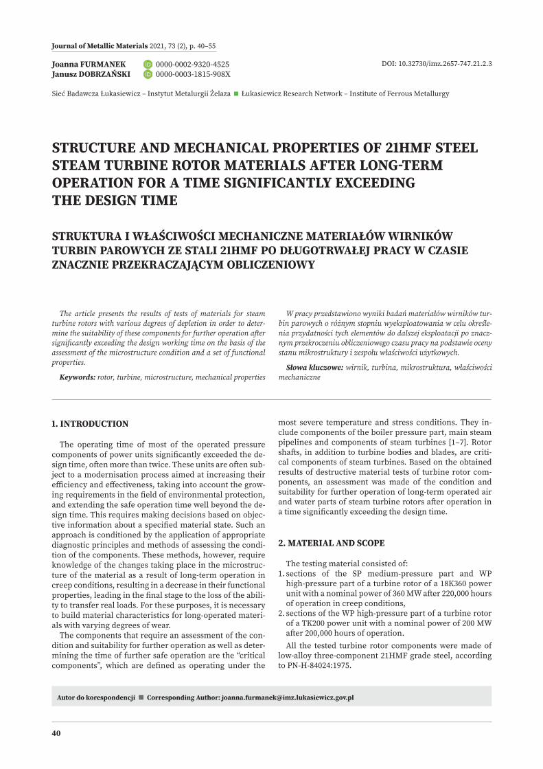
Journal of Metallic Materials 2021, 73 (2), p. 40–55 40 Autor do korespondencji < Corresponding Author: [email protected] Joanna FURMANEK 0000-0002-9320-4525 Janusz DOBRZAŃSKI 0000-0003-1815-908X Sieć Badawcza Łukasiewicz – Instytut Metalurgii Żelaza < Łukasiewicz Research Network – Institute of Ferrous Metallurgy STRUCTURE AND MECHANICAL PROPERTIES OF 21HMF STEEL STEAM TURBINE ROTOR MATERIALS AFTER LONG-TERM OPERATION FOR A TIME SIGNIFICANTLY EXCEEDING THE DESIGN TIME STRUKTURA I WŁAŚCIWOŚCI MECHANICZNE MATERIAŁÓW WIRNIKÓW TURBIN PAROWYCH ZE STALI 21HMF PO DŁUGOTRWAŁEJ PRACY W CZASIE ZNACZNIE PRZEKRACZAJĄCYM OBLICZENIOWY DOI: 10.32730/imz.2657-747.21.2.3 The article presents the results of tests of materials for steam turbine rotors with various degrees of depletion in order to deter- mine the suitability of these components for further operation aſter significantly exceeding the design working time on the basis of the assessment of the microstructure condition and a set of functional properties. Keywords: rotor, turbine, microstructure, mechanical properties W pracy przedstawiono wyniki badań materiałów wirników tur- bin parowych o różnym stopniu wyeksploatowania w celu określe- nia przydatności tych elementów do dalszej eksploatacji po znacz- nym przekroczeniu obliczeniowego czasu pracy na podstawie oceny stanu mikrostruktury i zespołu właściwości użytkowych. Słowa kluczowe: wirnik, turbina, mikrostruktura, właściwości mechaniczne most severe temperature and stress conditions. They in- clude components of the boiler pressure part, main steam pipelines and components of steam turbines [1–7]. Rotor shaſts, in addition to turbine bodies and blades, are criti- cal components of steam turbines. Based on the obtained results of destructive material tests of turbine rotor com- ponents, an assessment was made of the condition and suitability for further operation of long-term operated air and water parts of steam turbine rotors aſter operation in a time significantly exceeding the design time. 2. MATERIAL AND SCOPE The testing material consisted of: 1. sections of the SP medium-pressure part and WP high-pressure part of a turbine rotor of a 18K360 power unit with a nominal power of 360 MW aſter 220,000 hours of operation in creep conditions, 2. sections of the WP high-pressure part of a turbine rotor of a TK200 power unit with a nominal power of 200 MW aſter 200,000 hours of operation. All the tested turbine rotor components were made of low-alloy three-component 21HMF grade steel, according to PN-H-84024:1975. 1. INTRODUCTION The operating time of most of the operated pressure components of power units significantly exceeded the de- sign time, oſten more than twice. These units are oſten sub- ject to a modernisation process aimed at increasing their efficiency and effectiveness, taking into account the grow- ing requirements in the field of environmental protection, and extending the safe operation time well beyond the de- sign time. This requires making decisions based on objec- tive information about a specified material state. Such an approach is conditioned by the application of appropriate diagnostic principles and methods of assessing the condi- tion of the components. These methods, however, require knowledge of the changes taking place in the microstruc- ture of the material as a result of long-term operation in creep conditions, resulting in a decrease in their functional properties, leading in the final stage to the loss of the abili- ty to transfer real loads. For these purposes, it is necessary to build material characteristics for long-operated materi- als with varying degrees of wear. The components that require an assessment of the con- dition and suitability for further operation as well as deter- mining the time of further safe operation are the “critical components”, which are defined as operating under the
Transcript of STRUCTURE AND MECHANICAL PROPERTIES OF 21HMF STEEL …
Journal of Metallic Materials 2021, 73 (2), p. 40–55
40
Autor do korespondencji < Corresponding Author: [email protected]
Joanna FURMANEK 0000-0002-9320-4525 Janusz DOBRZAŃSKI 0000-0003-1815-908X
Sieć Badawcza Łukasiewicz – Instytut Metalurgii Żelaza < Łukasiewicz Research Network – Institute of Ferrous Metallurgy
STRUCTURE AND MECHANICAL PROPERTIES OF 21HMF STEEL STEAM TURBINE ROTOR MATERIALS AFTER LONG-TERM OPERATION FOR A TIME SIGNIFICANTLY EXCEEDING THE DESIGN TIME
STRUKTURA I WŁAŚCIWOŚCI MECHANICZNE MATERIAŁÓW WIRNIKÓW TURBIN PAROWYCH ZE STALI 21HMF PO DŁUGOTRWAŁEJ PRACY W CZASIE ZNACZNIE PRZEKRACZAJĄCYM OBLICZENIOWY
DOI: 10.32730/imz.2657-747.21.2.3
The article presents the results of tests of materials for steam turbine rotors with various degrees of depletion in order to deter-mine the suitability of these components for further operation after significantly exceeding the design working time on the basis of the assessment of the microstructure condition and a set of functional properties.
Keywords: rotor, turbine, microstructure, mechanical properties
W pracy przedstawiono wyniki badań materiałów wirników tur-bin parowych o różnym stopniu wyeksploatowania w celu określe-nia przydatności tych elementów do dalszej eksploatacji po znacz-nym przekroczeniu obliczeniowego czasu pracy na podstawie oceny stanu mikrostruktury i zespołu właściwości użytkowych.
Słowa kluczowe: wirnik, turbina, mikrostruktura, właściwości mechaniczne
most severe temperature and stress conditions. They in-clude components of the boiler pressure part, main steam pipelines and components of steam turbines [1–7]. Rotor shafts, in addition to turbine bodies and blades, are criti-cal components of steam turbines. Based on the obtained results of destructive material tests of turbine rotor com-ponents, an assessment was made of the condition and suitability for further operation of long-term operated air and water parts of steam turbine rotors after operation in a time significantly exceeding the design time.
2. MATERIAL AND SCOPE
The testing material consisted of:1. sections of the SP medium-pressure part and WP
high-pressure part of a turbine rotor of a 18K360 power unit with a nominal power of 360 MW after 220,000 hours of operation in creep conditions,
2. sections of the WP high-pressure part of a turbine rotor of a TK200 power unit with a nominal power of 200 MW after 200,000 hours of operation.All the tested turbine rotor components were made of
low-alloy three-component 21HMF grade steel, according to PN-H-84024:1975.
1. INTRODUCTION
The operating time of most of the operated pressure components of power units significantly exceeded the de-sign time, often more than twice. These units are often sub-ject to a modernisation process aimed at increasing their efficiency and effectiveness, taking into account the grow-ing requirements in the field of environmental protection, and extending the safe operation time well beyond the de-sign time. This requires making decisions based on objec-tive information about a specified material state. Such an approach is conditioned by the application of appropriate diagnostic principles and methods of assessing the condi-tion of the components. These methods, however, require knowledge of the changes taking place in the microstruc-ture of the material as a result of long-term operation in creep conditions, resulting in a decrease in their functional properties, leading in the final stage to the loss of the abili-ty to transfer real loads. For these purposes, it is necessary to build material characteristics for long-operated materi-als with varying degrees of wear.
The components that require an assessment of the con-dition and suitability for further operation as well as deter-mining the time of further safe operation are the “critical components”, which are defined as operating under the

Journal of Metallic Materials 2021, 73 (2), p. 40–55
41
The areas of the rotors from which the material for test-ing was taken and their operating parameters are sum-marised in Table 1 and, on the example of a 360 MW unit rotor after 220,000 operating hours, shown in Fig. 1. The test sites were selected in such a way as to obtain the differ-entiation of the material state from close to the initial state to the state corresponding to operation significantly above the limit temperature, for which creep is the dominant de-struction process.
The aim of the study was to search for a correlation be-tween changes in the structure and the corresponding mechanical properties in relation to the requirements for a typical initial state. The obtained results were also used to select the material states, from close to the initial state to the state with the highest degree of depletion, at which, in the next stage of the research, creep resistance and the determined degree of wear will be determined.
In order to achieve the above-defined goal, it was nec-essary to define and implement the testing agenda, which included:
Fig. 1. Method and location of collecting the material for testing on the example of the SP medium-pressure part and WP high-pressure part of a turbine rotor of a 18K360 power unit with a nominal power of 360 MW after approx. 220,000 operating hours: a) from SP medium-pressure part, b) from WP high-pressure partRys. 1. Sposób i miejsce pobrania materiału do badań na przykładzie części średnioprężnej SP i wysokoprężnej WP wirnika turbiny 18K360 blo-ku energetycznego o mocy nominalnej 360 MW po ok. 220 000 godzin eksploatacji: a) z części średnioprężnej SP, b) z części wysokoprężnej WP
a) b)
– structure examination in a scanning electron micro-scope,
– X-ray analysis of phase composition of precipitates, – test on strength properties at room temperature and elevated temperature close to the operating temperature,
– impact strength tests and determination of brittle state transition temperature.
3. RESULTS OF INVESTIGATION
3.1. STRUCTURE EXAMINATION IN SCANNING ELECTRON MICROSCOPE
The microstructure studies were performed using a scanning electron microscope on etched microsections taken from fragments of material sections of rotors of 200 and 360 MW unit steam turbines. The results of microstruc-ture examination for the TK200 turbine rotor material of

Journal of Metallic Materials 2021, 73 (2), p. 40–55
42
Table 1. Material for destructive testing of WP parts of the TK200 turbine rotor after approx. 200,000 hours of operation, and SP and WP parts of the 21HMF steel 18K360 rotor after approx. 220,000 hours of operation and their operating parameters in individual designated test areasTabela 1. Materiał do badań niszczących części WP wirnika turbiny TK200 po ok. 200 000 godzin eksploatacji oraz części SP i WP wirnika 18K360 po ok. 220 000 godzin eksploatacji wykonanych ze stali 21HMF i ich parametry pracy w poszczególnych wyznaczonych obszarach do badań
Steel grade Component name Identification of tested rotor section Testing location
Previous operating parameters
Timete, [hours]
TemperatureTe, [˚C]
Pressurepe, [MPa]
21HMF
high-pressure part of TK200 turbine rotor WP.TK200 outer disc periphery of the first
uncontrolled steam inlet stage 200,000 500 14.80
SP medium-pressure part of 18K360 turbine rotor
SP 1.1 K360 carrier thrust bearing pinSP part
220,000
40 0
SP 1.2 K360 gland-front 240 0
SP 2.1 K360 rotor’s SP part drum in steam inlet area 535 3.93
WP high-pressure part of 18K360 turbine rotor
WP 1.1 K360 WP rotor tip on safety control side 20 0
WP 1.2 K360 place of embedding of device components for rotor turning 286 0
WP 1.3 K360 rotor’s bearing pin 398 0
WP 2.1 K360 rotor drum in stage 12-13 region 510 14.2
WP 3.1 K360steam inlet in control wheel region 535 17.1
WP 3.4 K360
Fig. 2. Type and location of sampling on the example of: a) TK 200 turbine rotor WP high-pressure part material from the region of outer periphery of first uncontrolled stage after approx. 220,000 operating hours, b) material of the WP high-pressure part of the 18K360 turbine rotor in the region of the steam inlet in the region of the regulating wheel after approx. 200,000 operating hoursRys. 2. Rodzaj i miejsce pobrania próbek do badań na przykładzie: a) materiału części wysokoprężnej WP wirnika turbiny TK 200 z rejonu obrzeża zewnętrznego pierwszego stopnia nieregulowanego po ok. 220 000 godzin eksploatacji, b) materiału części wysokoprężnej WP wirni-ka turbiny 18K360 w rejonie wlot pary w rejonie koła regulacyjnego po ok. 200 000 godzin eksploatacji
Test samples: ACH – chemical composition follow-up, Rm – tensile strength, Re
t – yield strength at elevated temperature, KV – impact energy, ZG – structure on metallographic microsection, FR – fractograph of fractures, RTG – X-ray analysis of phase composition of precipitates, Rz L – creep rate in set condition Rz w – residual creep resistance,
a) b)

Journal of Metallic Materials 2021, 73 (2), p. 40–55
43
Fig. 3. Microstructure of the material in the area of the outer periphery of the disc of the first unregulated steam inlet stage of the WP high-pressure part of the TK 200 turbine rotor made of 21HMF steel after 200,000 hours of operation, observed on a crosswise microsection using a scanning electron microscopeRys. 3. Mikrostruktura materiału w obszarze zewnętrznego obrzeża tarczy pierwszego nieregulowanego stopnia wlotu pary części wysoko-prężnej WP wirnika turbiny TK 200 wykonanego ze stali 21HMF po 200 000 godzin eksploatacji obserwowana na zgładzie poprzecznym w ska-ningowym mikroskopie elektronowym
TK 200ID WP.TK200
steel 21HMF, hardness 195 HV10
CLASS 2/3 (I, a/b, O); te/tr = approx. 0.4
Fig. 4. Microstructure of the material of the SP medium-pressure part of the 18K360 turbine rotor after 220,000 hours of operation observed on etched transverse microsections using a scanning electron microscope: a) in carrier thrust bearing pin (ID SP 1.1 K360), b) in the front of the gland (ID SP 1.2 K360), c) in the drum in the steam inlet region (ID SP 2.1 K360)Rys. 4. Mikrostruktura materiału części średnioprężnej SP wirnika turbiny 18K360 po 220 tys. godzin eksploatacji obserwowana na traw-ionych poprzecznych zgładach metalograficznych w skaningowym mikroskopie elektronowym: a) w czopie łożyska oporowo-nośnego (ozn. SP 1.1 K360), b) w części przedniej dławicy (ozn. SP 1.2 K360), c) w bębnie w rejonie wlotu pary (ozn. SP 2.1 K360)
18K360ID SP 1.1 K360, ID SP 1.2 K360,
steel 21HMF, hardness 240 HV10 steel 21HMF, hardness 242 HV10
CLASS O (0, o, O); te/tr = 0
18K360ID SP 2.1 K360, steel 21HMF, hardness 247 HV10
CLASS 1 (0/I, o/a, O); te/tr = approx. 0.2
a) b) c)
Journal of Metallic Materials 2021, 73 (2), p. 40–55
44
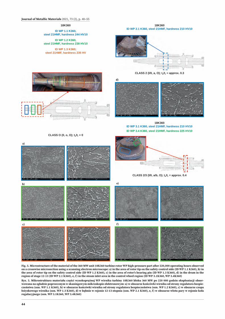
Fig. 5. Microstructure of the material of the 360 MW unit 18K360 turbine rotor WP high-pressure part after 220,000 operating hours observed on a crosswise microsection using a scanning electron microscope: a) in the area of rotor tip on the safety control side (ID WP 1.1 K360), b) in the area of rotor tip on the safety control side (ID WP 1.2 K360), c) in the area of rotor’s bearing pin (ID WP 1.3 K360), d) in the drum in the region of stage 12-13 (ID WP 2.1 K360), e, f) in the steam inlet area in the control wheel region (ID WP 3.1K360, WP 3.4K360)Rys. 5. Mikrostruktura materiału części wysokoprężnej WP wirnika turbiny 18K360 bloku 360 MW po 220 000 godzin eksploatacji obser-wowana na zgładzie poprzecznym w skaningowym mikroskopie elektronowym: a) w obszarze końcówki wirnika od strony regulatora bezpie- czeństwa (ozn. WP 1.1 K360), b) w obszarze końcówki wirnika od strony regulatora bezpieczeństwa (ozn. WP 1.2 K360), c) w obszarze czopa łożyskowego wirnika (ozn. WP 1.3 K360), d) w bębnie w rejonie 12-13 stopnia (ozn. WP 2.1 K360), e, f) w obszarze wlotu pary w rejonie koła regulacyjnego (ozn. WP 3.1K360, WP 3.4K360)
18K360
ID WP 1.1 K360, steel 21HMF, hardness 244 HV10
ID WP 1.2 K360, steel 21HMF, hardness 238 HV10
ID WP 1.3 K360; steel 21HMF, hardness 235 HV
CLASS O (0, o, O); te/tr = 0
18K360ID WP 2.1 K360, steel 21HMF, hardness 210 HV10
18K360ID WP 3.1 K360, steel 21HMF, hardness 210 HV10ID WP 3.4 K360, steel 21HMF, hardness 225 HV10
CLASS 2 (I/II, a, O); te/tr = approx. 0.3
CLASS 2/3 (I/II, a/b, O); te/tr = approx. 0.4
c)
b)
a)
f)
d)
e)
Journal of Metallic Materials 2021, 73 (2), p. 40–55
45
the 200 MW unit from the outer periphery of the disc of the first unregulated stage of the WP high-pressure part with a visible groove for fixing the blades after 200,000 operat-ing hours are shown in Fig. 3. The results of microstruc-ture examination for the SP medium-pressure part of the 18K360 turbine rotor after 220,000 operating hours in the material of the carrier thrust bearing pin (ID SP 1.1 K360), in the front part of the gland (ID SP 2.1 K360) and in the drum near the steam inlet (ID SP 3.1 K360) are shown in Fig. 4. The results of the studies of the microstructure of the WP high-pressure part of the 18K360 turbine rotor after 220,000 operating hours in the material of the rotor tip from the safety regulator side (ID WP 1.1 K360), rotor end from the safety regulator side (ID WP 1.2 K360), rotor’s bearing pin (ID WP 1.3 K360), in the drum in the region of stage
12–13 (ID WP 2.1 K360) and in the area of the steam inlet near the regulating wheel (ID WP 3.1K360, WP 3.4K360) is shown in Fig. 5.
For the proper assessment of the material condition, the classification of the structure condition was used with the corresponding degree of wear, which determine its degree of depletion. The assessment of the state of the structure was made in accordance with Łukasiewicz – IMŻ classifi-cation in the form of a designated structure class and the corresponding degree of wear based on the observation of the state of bainitic areas for the disclosed ferritic-bainitic structure, the degree of development of precipitation pro-cesses and the state of internal damage [1, 2]. The descrip-tion of the structure’s condition and the assessment result are presented in Table 2.
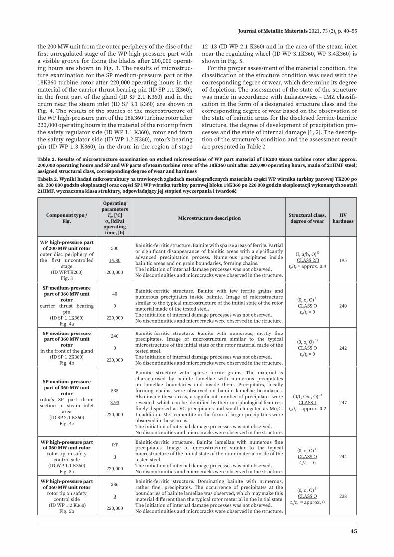
Table 2. Results of microstructure examination on etched microsections of WP part material of TK200 steam turbine rotor after approx. 200,000 operating hours and SP and WP parts of steam turbine rotor of the 18K360 unit after 220,000 operating hours, made of 21HMF steel; assigned structural class, corresponding degree of wear and hardnessTabela 2. Wyniki badań mikrostruktury na trawionych zgładach metalograficznych materiału części WP wirnika turbiny parowej TK200 po ok. 200 000 godzin eksploatacji oraz części SP i WP wirnika turbiny parowej bloku 18K360 po 220 000 godzin eksploatacji wykonanych ze stali 21HMF, wyznaczona klasa struktury, odpowiadający jej stopień wyczerpania i twardość
Component type / Fig.
Operating parameters
Tr, [°C]σr [MPa]
operating time, [h]
Microstructure description Structural class, degree of wear
HV hardness
WP high-pressure part of 200 MW unit rotor
outer disc periphery of the first uncontrolled
stage(ID WP.TK200)
Fig. 3
500
14.80
200,000
Bainitic-ferritic structure. Bainite with sparse areas of ferrite. Partial or significant disappearance of bainitic areas with a significantly advanced precipitation process. Numerous precipitates inside bainitic areas and on grain boundaries, forming chains. The initiation of internal damage processes was not observed.No discontinuities and microcracks were observed in the structure.
(I, a/b, O)1)
CLASS 2/3te/tr = approx. 0.4
195
SP medium-pressure part of 360 MW unit
rotorcarrier thrust bearing
pin(ID SP 1.1K360)
Fig. 4a
40
0
220,000
Bainitic-ferritic structure. Bainite with few ferrite grains and numerous precipitates inside bainite. Image of microstructure similar to the typical microstructure of the initial state of the rotor material made of the tested steel. The initiation of internal damage processes was not observed.No discontinuities and microcracks were observed in the structure.
(0, o, O) 1) CLASS Ote/tr = 0
240
SP medium-pressure part of 360 MW unit
rotorin the front of the gland
(ID SP 1.2K360)Fig. 4b
240
0
220,000
Bainitic-ferritic structure. Bainite with numerous, mostly fine precipitates. Image of microstructure similar to the typical microstructure of the initial state of the rotor material made of the tested steel.The initiation of internal damage processes was not observed.No discontinuities and microcracks were observed in the structure.
(0, o, O) 1)
CLASS Ote/tr = 0
242
SP medium-pressure part of 360 MW unit
rotorrotor’s SP part drum section in steam inlet
area(ID SP 2.1 K360)
Fig. 4c
535
3.93
220,000
Bainitic structure with sparse ferrite grains. The material is characterised by bainite lamellae with numerous precipitates on lamellae boundaries and inside them. Precipitates, locally forming chains, were observed on bainite lamellae boundaries. Also inside these areas, a significant number of precipitates were revealed, which can be identified by their morphological features: finely-dispersed as VC precipitates and small elongated as Mo2C. In addition, M3C cementite in the form of larger precipitates were observed in these areas. The initiation of internal damage processes was not observed.No discontinuities and microcracks were observed in the structure.
(0/I, O/a, O) 1) CLASS 1
te/tr = approx. 0.2247
WP high-pressure partof 360 MW unit rotor
rotor tip on safety control side
(ID WP 1.1 K360)Fig. 5a
RT
0
220,000
Bainitic-ferritic structure. Bainite lamellae with numerous fine precipitates. Image of microstructure similar to the typical microstructure of the initial state of the rotor material made of the tested steel. The initiation of internal damage processes was not observed.No discontinuities and microcracks were observed in the structure.
(0, o, O) 1)
CLASS Ote/tr = 0
244
WP high-pressure partof 360 MW unit rotor
rotor tip on safety control side
(ID WP 1.2 K360)Fig. 5b
286
0
220,000
Bainitic-ferritic structure. Dominating bainite with numerous, rather fine, precipitates. The occurrence of precipitates at the boundaries of bainite lamellae was observed, which may make this material different than the typical rotor material in the initial stateThe initiation of internal damage processes was not observed.No discontinuities and microcracks were observed in the structure.
(0, o, O) 1)
CLASS Ote/tr = approx. 0
238
Journal of Metallic Materials 2021, 73 (2), p. 40–55
46
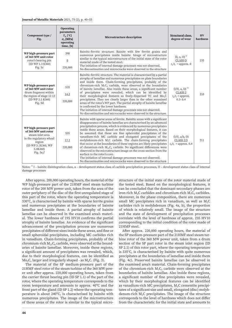
Component type / Fig.
Operating parameters
Tr, [°C]σr [MPa]
operating time, [h]
Microstructure description Structural class, degree of wear
HV hardness
WP high-pressure partof 360 MW unit rotor
rotor’s bearing pin (ID WP 1.3 K360)
Fig. 5c
398
0
220,000
Bainitic-ferritic structure. Bainite with few ferrite grains and numerous precipitates inside bainite. Image of microstructure similar to the typical microstructure of the initial state of the rotor material made of the tested steel. The initiation of internal damage processes was not observed.No discontinuities and microcracks were observed in the structure
(0, o, O) 1)
CLASS Ote/tr = approx. 0
235
WP high-pressure partof 360 MW unit rotordrum fragment within
the region of stage 12-13 (ID WP 2.1 K360)
Fig. 5d
510
14.2
220,000
Bainitic-ferritic structure. The material is characterised by a partial atrophy of lamellae and numerous precipitates on plate boundaries and inside them. Chain-forming precipitates, probably of the chromium-rich M7C3 carbide, were observed at the boundaries of bainite lamellae. Also inside these areas, a significant number of precipitates were revealed, which can be identified by their morphological features as finely-dispersed VC and Mo2C precipitates. They are clearly larger than in the other examined areas of the rotor’s WP part. The partial atrophy of bainite lamellae is confirmed by the lower hardness.The initiation of internal damage processes was not observed.No discontinuities and microcracks were observed in the structure.
(I/II, a, O) 1)
CLASS 2te/tr = approx.
0.3- 0.4
210
WP high-pressure partof 360 MW unit rotor
steam inlet area in the regulatory wheel
region (ID WP 3.1K360, WP
3.4K360)Fig. 5e,f
535
17.1
220,000
Bainite with sparse areas of ferrite. Bainitic areas with a significant disappearance of bainite lamellae are characterised by an advanced precipitation process, which is evidenced by numerous precipitates inside these areas. Based on their morphological features, it can be assumed that these are fine spheroidal precipitates of the vanadium-rich MC carbide and elongated precipitates of the molybdenum-rich M2C carbide. The chain-forming precipitates that occur at the boundaries of these regions are likely precipitates of chromium-rich M23C6 carbide. No significant differences were observed in the microstructure image on the cross-section from the surface to the rotor’s core.The initiation of internal damage processes was not observed.No discontinuities and microcracks were observed in the structure
(I/II, a/b, O) CLASS 2/3
te/tr = approx. 0.4211
Notes: 1) I – bainite disintegration class, a – development status class of carbide precipitation processes, O – development status class of internal damage processes
After approx. 200,000 operating hours, the material of the WP high-pressure part of the 21HMF steel steam turbine rotor of the 200 MW power unit, taken from the area of the outer periphery of the disc of the first unregulated stage of this part of the rotor, where the operating temperature is 530°C, is characterised by bainite with sparse ferrite grains and numerous precipitates at the boundaries of bainite lamellae and inside them. A partial atrophy of bainite lamellae can be observed in the examined area’s materi-al. The lower hardness of 195 HV10 confirms the partial atrophy of bainite lamellae. An evidence of the significant advancement of the precipitation process are numerous precipitates of different sizes inside these areas, and fine or small spheroidal precipitates, including MC carbides rich in vanadium. Chain-forming precipitates, probably of the chromium-rich M23C6 carbide, were observed at the bound-aries of bainite lamellae. Moreover, inside these regions, a significant amount of precipitates was revealed, which, due to their morphological features, can be identified as Mo2C, larger and irregularly shaped - as M6C. (Fig. 3).
The material of the SP medium-pressure part of the 21HMF steel rotor of the steam turbine of the 360 MW pow-er unit after approx. 220,000 operating hours, taken from the carrier thrust bearing pin (ID SP 1.1) of the part of the rotor, where the operating temperature corresponds to the room temperature and amounts to approx. 40ºC and the front part of the gland (ID SP 1.2) where the operating tem-perature is about 240ºC, is characterised by bainite with numerous precipitates. The image of the microstructure of these areas of the rotor is similar to the typical micro-
structure of the initial state of the rotor material made of the tested steel. Based on the morphological features, it can be concluded that the dominant secondary phases are iron-rich M3C carbides and chromium-rich M7C3 carbides. Moreover, in the phase composition, there are numerous small MC precipitates rich in vanadium, as well as M2C carbides rich in molybdenum (Fig. 4a, b), the proportion of which is relatively small. The image of the structure and the state of development of precipitation processes correlate with the level of hardness of approx. 235 HV10 corresponding to the initial condition of the rotor made of 21HMF steel.
After approx. 220,000 operating hours, the material of the SP medium-pressure part of the 21HMF steel steam tur-bine rotor of the 360 MW power unit, taken from a drum section of the SP part rotor in the steam inlet region (ID SP 2.1) of this rotor part, where the operating temperature is 535°C, is characterised by bainite with quite numerous precipitates at the boundaries of lamellae and inside them (Fig. 4c). Preserved bainite lamellae can be observed in the examined area’s material. Chain-forming precipitates of the chromium-rich M7C3 carbide were observed at the boundaries of bainite lamellae. Also inside these regions, a significant number of fine precipitates were revealed, which by their morphological features can be identified as vanadium-rich MC precipitates, M3C cementite precipi-tates of a significant size and small, elongated (disc) molyb-denum-rich M2C precipitates. The image of the structure corresponds to the level of hardness which does not differ from the characteristic for the initial state and amounts to

Journal of Metallic Materials 2021, 73 (2), p. 40–55
47
approx. 235 HV10. In this material, after such a long use at the temperature above the limit, the initiation of internal damage processes was not revealed.
The material of the WP high-pressure part of the 21HMF steel steam turbine rotor of the 360 MW power unit after approx. 220,000 operating hours, taken from the end of the rotor from the safety regulator side (ID WP 1.1, WP 1.2) of the part of the rotor, where the operating temper-ature corresponds to a correspondingly similar to room temperature and amounting to 286°C s characterised by bainite with quite numerous precipitates. The image of the microstructure of the rotor tip material is similar to the typical microstructure of the initial state of the rotor ma-terial made of the tested steel (Fig. 5a, b). The precipitates present in the structure are mainly M3C cementite and nu-merous fine vanadium-rich MC particles, as well as a small amount of molybdenum-rich M2C carbides.
After approx. 220,000 operating hours, the material of the WP high-pressure part of the 21HMF steel steam turbine rotor of the 360 MW power unit, taken from a drum section from the area of 12–13th stage (ID WP 2.1) of the rotor part, where the operating temperature is 510°C, is characterised by bainite with numerous precipitates at the boundaries of lamellae and inside them (Fig. 5d). A partial atrophy of bainite lamellae can be observed in the examined area’s material. Precipitates of the chromium-rich M7C3 carbide,
forming chain systems, were observed at the boundaries of bainite lamellae. Moreover, a considerable amount of dis-persed precipitates, vanadium-rich MC type carbides and M2C molybdenum carbides were revealed within these re-gions. Their geometric features are relatively larger than in the other examined areas of the rotor’s WP part. The partial atrophy of bainite lamellae is also confirmed by the lower hardness. Despite such a long use at the temperature above the limit, the initiation of internal damage processes was not revealed in the material.
After approx. 220,000 operating hours, the material of the WP high-pressure part of the 21HMF steel steam tur-bine rotor of the 360 MW power unit, taken from the steam inlet area within the control wheel region (ID WP 3.1) of this rotor part, where the operating temperature is 535°C, is characterised by bainite with numerous precipitates at the boundaries of lamellae and inside them (Fig. 5e). A sig-nificant atrophy of bainite lamellae can be observed in the examined area’s material. Chain-forming precipitates, probably of the M7C3 carbide, were observed at the bound-aries of bainite lamellae. Within these regions, a consid-erable amount of M3C cementite coagulated precipitates and MC fine precipitates, as well as a small proportion of molybdenum-rich M2C carbides, were observed. The phase composition determined in X-ray studies, including their type and relative content, confirms a significant degree of
Table 3. Results of X-ray qualitative phase analysis of the deposit of electrolytically isolated material precipitates of the tested sections of the WP part of the TK200 unit turbine rotor after 200,000 hours of operation, and the SP and WP parts of the 18K360 unit turbine rotor after 220,000 hours of operationTabela 3. Wyniki rentgenowskiej jakościowej analizy fazowej osadu wyizolowanych elektrolitycznie wydzieleń materiału badanych wycinków części WP wirnika turbiny bloku TK200 po 200 000 godzin eksploatacji oraz części SP i WP wirnika turbiny bloku 18K360 po 220 000 godzin eksploatacji
Tested component Tested material Identified phase components and their relative content
Precipitate development degree
classDegree of wear te/tr
WP high-pressure part of TK200 turbine rotor after approx. 200,000operating hours
outer disc periphery of the first uncontrolled stage (ID WP.TK200)made of 21HMF steel
Cr7C3 – main phaseFe 3C – main phaseMo2C – highVC – mediumCr23C6 – lowMo3Fe3C – lowFe23C6 – trace amount
class a/bapprox. 0.4
SP medium-pressure part of 18K360 turbine rotor after approx. 220,000operating hours
carrier thrust bearing pin(ID SP 1.1 K360)made of 21HMF steel
M3C – main phaseM7C3 – main phaseM2C – high VC – medium MC – medium
class o0
rotor’s SP part drum section in steam inlet area(ID SP 2.1 K360)made of 21HMF steel
M3C – main phaseM7C3 – main phaseM2C – medium VC – medium MC – medium
class o/aapprox. 0.2
WP high-pressure part of 18K360 turbine rotorafter approx. 220,000operating hours
rotor tip on safety control side (ID WP 1.1 K360)made of 21HMF steel
Fe 3C – main phaseM7C3 – highVC – mediumMo2C – low
class o0
drum fragment within the region of stage 12–13 (ID WP 2.1 K360)made of 21HMF steel
M7C3 – main phaseFe3C – highMo2C – high VC – mediumMC – medium
class aapprox. 0.3
steam inlet area in the regulatory wheel region (ID WP 3.1 K360)made of 21HMF steel
M7C3 – main phaseFe3C – highVC – mediumMC – lowMo2C – low
class a/bapprox. 0.3-0.4

Journal of Metallic Materials 2021, 73 (2), p. 40–55
48
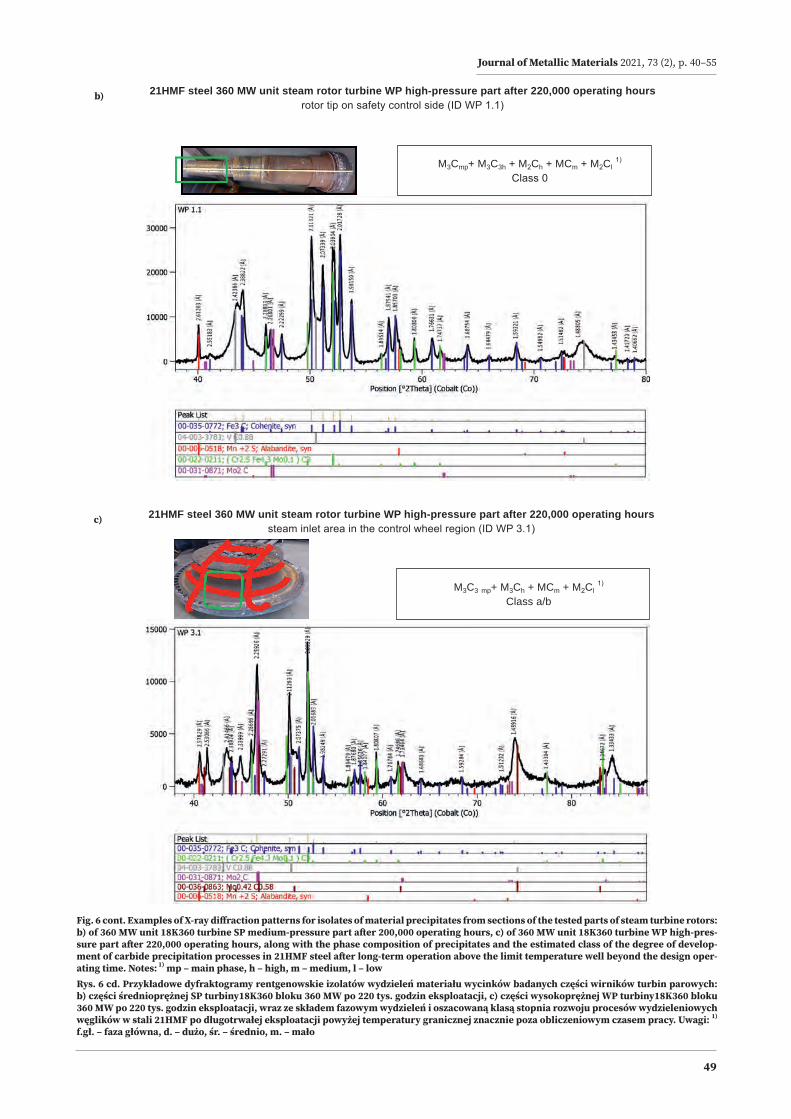
Fig. 6. Examples of X-ray diffraction patterns for isolates of material precipitates from sections of the tested parts of steam turbine rotors: a) of 200 MW unit TK200 turbine WP high-pressure part after 200,000 operating hours, after 220,000 operating hours, along with the phase composition of precipitates and the estimated class of the degree of development of carbide precipitation processes in 21HMF steel after long-term operation above the limit temperature well beyond the design operating time. Notes: 1) mp – main phase, h – high, m – medium, l – lowRys. 6. Przykładowe dyfraktogramy rentgenowskie izolatów wydzieleń materiału wycinków badanych części wirników turbin parowych: a) części wysokoprężnej WP turbiny TK200 bloku 200 MW po 200 tys. godzin eksploatacji, , po 220 tys. godzin eksploatacji, wraz ze składem fazowym wydzieleń i oszacowaną klasą stopnia rozwoju procesów wydzieleniowych węglików w stali 21HMF po długotrwałej eksploatacji powyżej temperatury granicznej znacznie poza obliczeniowym czasem pracy. Uwagi: 1) f.gł. – faza główna, d. – dużo, śr. – średnio, m. – mało
21HMF steel 200 MW unit steam rotor turbine WP high-pressure part after 200,000 operating hoursouter disc periphery of the first uncontrolled stage (ID WP.TK200)
M7C3 mp+ M3C mp + M2Ch + MCm + M23C6 l + M6C l 1)
Class a/b
a)
changes in this respect as a result of long-term operation (Table 4). In addition, the image of the structure and the state of development of precipitation processes correlate with the hardness level of approx. 210 HV10, which is ap-prox. 30 units lower than the hardness characteristic for the initial state. Also in this material, despite such a long use at the temperature significantly above the limit, the in-itiation of internal damage processes was not revealed in the material.
3.2. X-RAY ANALYSIS OF PHASE COMPOSITION OF PRECIPITATES
The X-ray analysis of the phase composition of the pre-cipitates was carried out on the precipitate obtained by dissolving the matrix using the electrolytic method of the material of the tested turbine rotor sections. The tests were performed with an Empyrean X-ray diffractometer using cobalt radiation in a configuration with a Pixcel detector. The obtained results of the X-ray diffraction analysis of the isolated carbide deposit allowed to reveal the types of precipitates occurring and to define their content in the tested materials, which is summarised in Table 3. Selected examples of the obtained diffraction patterns are shown in Fig. 6. The diffraction pattern of the precipitates from the material of the outer periphery of the disc of the first unregulated stage of the WP high-pressure part of the TK 200 turbine rotor of the 200 MW unit after 200,000 operat-ing hours is shown in Fig. 6a, while Fig. 6b illustrates the phase composition of the rotor tip material from the side
of the safety regulator of the SP medium-pressure part, and Fig. 6c – from the area of the steam inlet in the area of the control wheel of the WP high-pressure part of the 360 MW 18K360 unit turbine rotor after 220,000 operating hours. Based on the obtained sequence of precipitates, the degree of development of precipitation processes in the tested low-alloy 21HMF steel was estimated in accordance with the own classification of Łukasiewicz – IMŻ [1, 2].
The state of development of the precipitation processes of the outer periphery of the disc of the first unregulat-ed stage of the tested WP part (ID WP.TK200) of the rotor of the 200 MW unit after long-term operation for 200,000 hours corresponds to class a/b and the degree of wear te/tr = approx. 0.4. The state of development of the precipi-tation processes of the carrier thrust bearing pin material (ID SP 1.1K360) of the SP part of the 360 MW unit rotor after long-term operation for approx. 220,000 hours corresponds to class o and degree of wear te/tr = 0, i.e. the initial value of the tested 21HMF steel. The state of development of the precipitation processes of the rotor’s SP part drum material in the steam inlet region (ID SP2.1 K360) of this rotor after long-term operation for approx. 220,000 hours corresponds to class o/a and the degree of wear te/tr = up to 0.2. The state of development of the precipitation processes of the rotor tip on the side of the safety regulator of the tested WP part (ID WP 1.1K360) of the 360 MW unit rotor after long-term operation for approx. 220,000 hours corresponds to class o and degree of wear te/tr = 0, i.e. corresponds to the initial value of the tested 21HMF steel. The state of development
Journal of Metallic Materials 2021, 73 (2), p. 40–55
49
Fig. 6 cont. Examples of X-ray diffraction patterns for isolates of material precipitates from sections of the tested parts of steam turbine rotors: b) of 360 MW unit 18K360 turbine SP medium-pressure part after 200,000 operating hours, c) of 360 MW unit 18K360 turbine WP high-pres-sure part after 220,000 operating hours, along with the phase composition of precipitates and the estimated class of the degree of develop-ment of carbide precipitation processes in 21HMF steel after long-term operation above the limit temperature well beyond the design oper-ating time. Notes: 1) mp – main phase, h – high, m – medium, l – lowRys. 6 cd. Przykładowe dyfraktogramy rentgenowskie izolatów wydzieleń materiału wycinków badanych części wirników turbin parowych: b) części średnioprężnej SP turbiny18K360 bloku 360 MW po 220 tys. godzin eksploatacji, c) części wysokoprężnej WP turbiny18K360 bloku 360 MW po 220 tys. godzin eksploatacji, wraz ze składem fazowym wydzieleń i oszacowaną klasą stopnia rozwoju procesów wydzieleniowych węglików w stali 21HMF po długotrwałej eksploatacji powyżej temperatury granicznej znacznie poza obliczeniowym czasem pracy. Uwagi: 1) f.gł. – faza główna, d. – dużo, śr. – średnio, m. – mało
21HMF steel 360 MW unit steam rotor turbine WP high-pressure part after 220,000 operating hourssteam inlet area in the control wheel region (ID WP 3.1)
M3C3 mp+ M3Ch + MCm + M2Cl 1)
Class a/b
c)
21HMF steel 360 MW unit steam rotor turbine WP high-pressure part after 220,000 operating hoursrotor tip on safety control side (ID WP 1.1)
M3Cmp+ M3C3h + M2Ch + MCm + M2Cl 1)
Class 0
b)

Journal of Metallic Materials 2021, 73 (2), p. 40–55
50
Table 4. Test results for strength properties at room temperature and elevated temperature for sections of the SP medium-pressure and WP high-pressure part of the 21HMF steel 18K360 turbine rotor after 220,000 hours of operationTabela 4. Wyniki badań właściwości wytrzymałościowych w temperaturze pokojowej i podwyższonej materiałów wycinków części średnio-prężnej SP i wysokoprężnej WP wirnika turbiny 18K360 po 220 000 godzin eksploatacji wykonanych ze stali 21HMF
Component nameoperating time
Testing location identification
Testing temperature
Tt, [oC]
Strength properties
Tensile strength1)
Rm (Rmt), [MPa]
Yield strength1)
Re (Ret), [MPa]
Elongation1)
A5, [%]Narrowing
Z, [%]
18K360SP medium-pressure
part220,000 operating
hours
carrier thrust bearing pin
ID SP 1.1 K360
20 740; 740 (min. 686) 607; 606 (min. 588) 19.4; 20.6 (min. 16) 68; 67
200 667 544 (min. 510) 19.2 68
300 649 536 (min. 481) 16.4 66
450 588 483 (min. 402) 19.0 68
500 541 470 (min. 353) 20.0 73
18K360SP medium-pressure
part220,000 operating
hours
place of embedding of device
components for rotor turning
ID SP 1.2 K360
20 751 (min. 686) 630.5 (min. 588) 20.3 (min. 16) 70
200 680 570 (min. 510) 17.6 69
300 671 563 (min. 481) 15.6 66
450 600 511 (min. 402) 18.4 72
500 550 497 (min. 353) 17.2 76
rotor’s SP part drum section in steam
inlet areaID SP 2.1 K360
20 753; 760 (min. 686) 614; 619 (min. 588) 20.8; 21.4 (min.16) 64; 66
200 679 556 (min. 510) 20.2 69
300 659 538 (min. 481) 16.8 64
450 585 491 (min. 402) 15.6 64
500 532 463 (min. 353) 19.8 71
18K360WP high-pressure
part220,000 operating
hours
rotor tip on safety control side
ID WP 1.1 K360
20 738; 740 (min. 686) 619; 621 (588) 20.4; 20.2 (min. 16) 70; 70
200 674 566 (min. 510) 17.8 69
300 661 558 (min. 481) 16.2 67
450 588 508 (min. 402) 16.4 71
500 543 484 (min. 353) 19.6 78
place of embedding of device
components for rotor turning
ID WP 1.2 K36)
20 750; 752 (min. 686) 629; 632 (588) 20.6 (min. 16) 71
200 680 570 (min. 510) 17.6 69
300 671 563 (min. 481) 15.6 66
450 600 511 (min. 402) 18.4 72
500 550 497 (min. 3532)) 17.2 76
drum fragment within the region of
stage 12-13 WP 2.1 K360
20 650; 650 (min. 686) 508; 507 (588) 22.4; 22.2 (min. 16) 72; 70
200 580 463 (min. 510) 20.0 71
300 561 448 (min. 481) 18.2 70
450 501 416 (min. 402) 18.8 71
500 459 398 (min. 353) 16.4 74
steam inlet area in the regulatory
wheel region WP 3.1 K360
20 668;674 (min. 686) 519; 538 (min. 588) 19.4; 20.0 (min. 16) 64; 66
200 589 444 (min. 510) 17.2 64
300 569 419 (min. 481) 17.2 59
450 491 395 (min. 402) 19.4 61
500 436 357 (min. 353) 24.2 651) ( ) minimum values according to the requirements for the material in its initial state according to PN-70 / H-94009 are stated in parentheses
do not meet the requirements for the initial state
of the precipitation processes of the drum’s material in the region of stage 12–13 of the tested WP part (ID WP2.1 K360) of the 360 MW unit rotor after long-term operation for 220,000 hours corresponds to class a and the degree of wear te/tr = approx. 0.3. The state of development of the precip-
itation processes of the material in the seam inlet area in the region of the control wheel of the tested WP part (ID WP3.1 K360) of the 360 MW unit rotor after long-term op-eration for 220,000 hours corresponds to class a/b and the degree of wear te/tr = approx. 0.3-0.4.
Journal of Metallic Materials 2021, 73 (2), p. 40–55
51
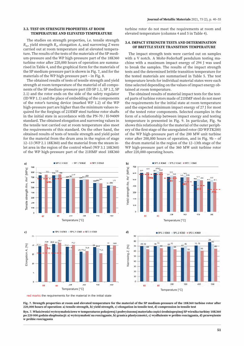
3.3. TEST ON STRENGTH PROPERTIES AT ROOM TEMPERATURE AND ELEVATED TEMPERATURE
The studies on strength properties, i.e. tensile strength Rm, yield strength Re, elongation A5 and narrowing Z were carried out at room temperature and at elevated tempera-ture. The results of the tests of the materials of the SP medi-um-pressure and the WP high-pressure part of the 18K360 turbine rotor after 220,000 hours of operation are summa-rised in Table 4, and the graphical form for the materials of the SP medium-pressure part is shown in Fig. 7, and for the materials of the WP high-pressure part – in Fig. 8.
The obtained results of tests of tensile strength and yield strength at room temperature of the material of all compo-nents of the SP medium-pressure part (ID SP 1.1, SP 1.2, SP 2.1) and the rotor ends on the side of the safety regulator (ID WP 1.1) and the place of embedding of the components of the rotor’s turning device (marked WP 1.2) of the WP high-pressure part are higher than the minimum values re-quired for the forgings of 21HMF steel turbine rotor shafts in the initial state in accordance with the PN-70 / H-94009 standard. The obtained elongation and narrowing values in the tensile test carried out at room temperature also meet the requirements of this standard. On the other hand, the obtained results of tests of tensile strength and yield point for the material from the drum area in the region of stage 12–13 (WP 2.1 18K360) and the material from the steam in-let area in the region of the control wheel (WP 3.1 18K360) of the WP high-pressure part of the 21HMF steel 18K360
turbine rotor do not meet the requirements at room and elevated temperature (columns 4 and 5 in Table 4).
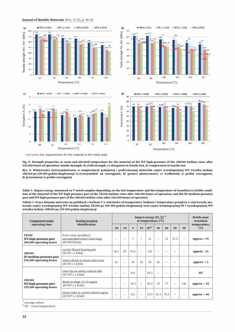
3.4. IMPACT STRENGTH TESTS AND DETERMINATION OF BRITTLE STATE TRANSITION TEMPERATURE
The impact strength tests were carried out on samples with a V notch. A Mohr-Federhaff pendulum testing ma-chine with a maximum impact energy of 294 J was used to break the samples. The results of the impact strength tests and the determined brittle transition temperature for the tested materials are summarised in Table 5. The test temperature levels for individual material states were each time selected depending on the values of impact energy ob-tained at room temperature.
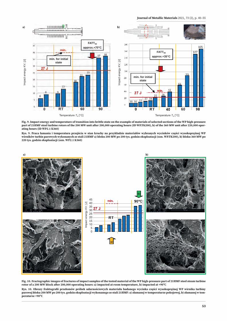
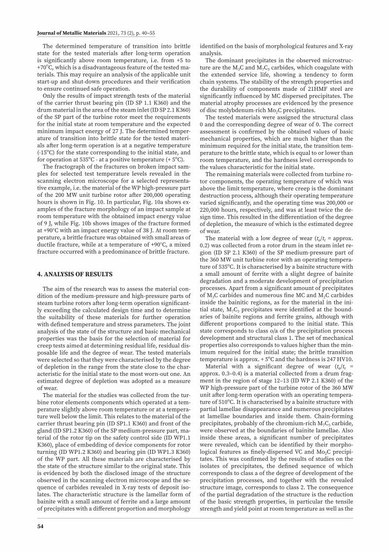
The obtained results of material impact tests for the test-ed parts of turbine rotors made of 21HMF steel do not meet the requirements for the initial state at room temperature and the expected minimum impact energy of 27 J for most of the tested rotor components. Selected examples in the form of a relationship between impact energy and testing temperature is presented in Fig. 9. In particular, Fig. 9a shows this relationship for the material of the outer periph-ery of the first stage of the unregulated rotor (ID WP.TK200) of the WP high-pressure part of the 200 MW unit turbine rotor after 200,000 hours of operation, and in Fig. 9b – of the drum material in the region of the 12–13th stage of the WP high-pressure part of the 360 MW unit turbine rotor after 220,000 operating hours.
Fig. 7. Strength properties at room and elevated temperature for the material of the SP medium-pressure of the 18K360 turbine rotor after 220,000 hours of operation: a) tensile strength, b) yield strength, c) elongation in tensile test, d) compression in tensile testRys. 7. Właściwości wytrzymałościowe w temperaturze pokojowej i podwyższonej materiału części średnioprężnej SP wirnika turbiny 18K360 po 220 000 godzin eksploatacji: a) wytrzymałość na rozciąganie, b) granica plastyczności, c) wydłużenie w próbie rozciągania, d) przewężenie w próbie rozciągania
Nar
row
ing
Z, [%
}
Temperature [°C]
Elon
gatio
n A
, [%
}
Temperature [°C]
Tens
ile s
treng
th R
m, R
mt, [M
Pa]
Temperature [°C]
Yiel
d st
reng
th R
e, R
et, [MPa
]
Temperature [°C]
red marks the requirements for the material in the initial state
c)
a)
d)
b)
Journal of Metallic Materials 2021, 73 (2), p. 40–55
52
Fig. 8. Strength properties at room and elevated temperature for the material of the WP high-pressure of the 18K360 turbine rotor after 220,000 hours of operation: tensile strength, b) yield strength, c) elongation in tensile test, d) compression in tensile testRys. 8. Właściwości wytrzymałościowe w temperaturze pokojowej i podwyższonej materiału części wysokoprężnej WP wirnika turbiny 18K360 po 220 000 godzin eksploatacji: a) wytrzymałość na rozciąganie, b) granica plastyczności, c) wydłużenie w próbie rozciągania, d) przewężenie w próbie rozciągania
Nar
row
ing
Z, [%
}
Temperature [°C]
Elon
gatio
n A
, [%
}
Temperature [°C]
Tens
ile s
treng
th R
m, R
mt, [M
Pa]
Temperature [°C]
Yiel
d st
reng
th R
e, R
et, [MPa
]
Temperature [°C]
red marks the requirements for the material in the initial state
c)
a)
d)
b)
Table 5. Impact energy measured on V-notch samples depending on the test temperature and the temperature of transition to brittle condi-tion of the material of the WP high-pressure part of the TK200 turbine rotor after 200,000 hours of operation, and the SP medium-pressure part and WP high-pressure part of the 18K360 turbine rotor after 220,000 hours of operationTabela 5. Praca łamania mierzona na próbkach z karbem V w zależności od temperatury badania i temperatura przejścia w stan kruchy ma-teriału części wysokoprężnej WP wirnika turbiny TK200 po 200 000 godzin eksploatacji oraz części średnioprężnej SP i wysokoprężnej WP wirnika turbiny 18K360 po 220 000 godzin eksploatacji
Component nameoperating time
Testing location identification
Impact energy KV, [J] 1)
at temperature, [ºC]Brittle state transition
temperature, [oC]-20 -10 0 10 RT2) 40 60 90 98
TK200WP high-pressure part 200,000 operating hours
from outer periphery uncontrolled rotor’s first stage(ID WP.TK200)
– – 7 – 11 – 21 37.5 – approx. +70
18K360SP medium-pressure part 220,000 operating hours
carrier thrust bearing pin(ID SP 1.1 K360) 18.3 30 53.5 – 132 – – – – approx. -15
rotor’s drum in steam inlet area(ID SP 2.1 K360) 23 – 24 32 42 52 – – – approx. + 5
18K360WP high-pressure part 220,000 operating hours
rotor tip on safety control side(ID WP 1.1 K360) – – 8.6 24.3 – – – – RT
drum in stage 12-13 region(ID WP 2.1 K360) – – 10.3 – 20.3 35 77 – 156 approx. + 35
steam inlet in control wheel region(ID WP 3.1 K360) – – 8.6 – 19.3 33.3 79.3 – – approx. + 40
1) average values 2) RT – room temperature
Journal of Metallic Materials 2021, 73 (2), p. 40–55
53
Fig. 9. Impact energy and temperature of transition into brittle state on the example of materials of selected sections of the WP high-pressure part of 21HMF steel turbine rotors of the 200 MW unit after 200,000 operating hours (ID WP.TK200), b) of the 360 MW unit after 220,000 oper-ating hours (ID WP2.1 K360)Rys. 9. Praca łamania i temperatura przejścia w stan kruchy na przykładzie materiałów wybranych wycinków części wysokoprężnej WP wirników turbin parowych wykonanych ze stali 21HMF a) bloku 200 MW po 200 tys. godzin eksploatacji (ozn. WP.TK200), b) bloku 360 MW po 220 tys. godzin eksploatacji (ozn. WP2.1 K360)
FATT50
approx.+70°CFATT50
approx.+35°C
min. for initial state
min. for initial state
Impa
ct e
nerg
y K
V, [
J]Temperature Tb [°C]Temperature Tb [°C]
Impa
ct e
nerg
y K
V, [
J]
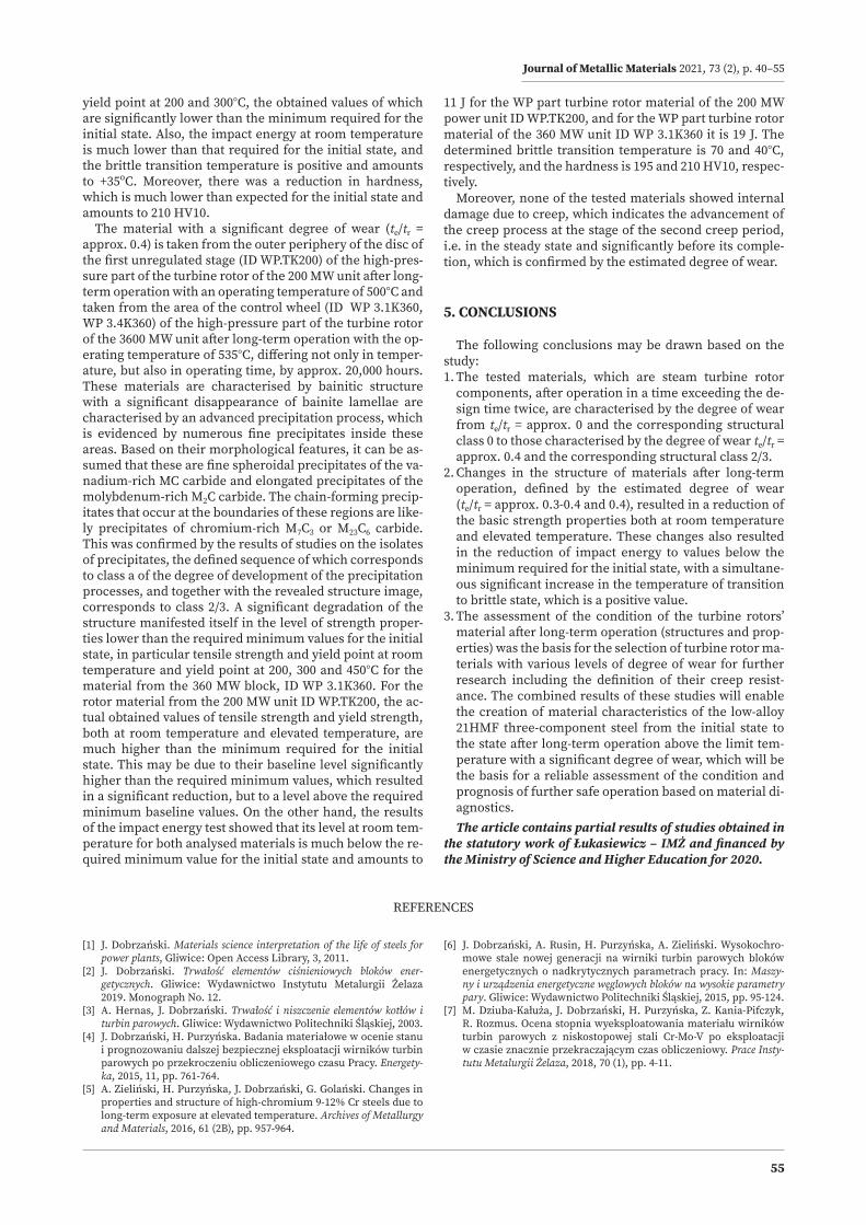
Fig. 10. Fractographic images of fractures of impact samples of the tested material of the WP high-pressure part of 21HMF steel steam turbine rotor of a 200 MW block after 200,000 operating hours: a) impacted at room temperature, b) impacted at +90ºCRys. 10. Obrazy fraktografii przełomów próbek udarnościowych materiału badanego wycinka części wysokoprężnej WP wirnika turbiny parowej bloku 200 MW po 200 tys. godzin eksploatacji wykonanego ze stali 21HMF: a) złamanej w temperaturze pokojowej, b) złamanej w tem-peraturze +90ºC
a) b)
a) b)
a)
b)
Impa
ct e
nerg
y K
V, [
J]
454035302520151050
Journal of Metallic Materials 2021, 73 (2), p. 40–55
54
The determined temperature of transition into brittle state for the tested materials after long-term operation is significantly above room temperature, i.e. from +5 to +70oC, which is a disadvantageous feature of the tested ma-terials. This may require an analysis of the applicable unit start-up and shut-down procedures and their verification to ensure continued safe operation.
Only the results of impact strength tests of the material of the carrier thrust bearing pin (ID SP 1.1 K360) and the drum material in the area of the steam inlet (ID SP 2.1 K360) of the SP part of the turbine rotor meet the requirements for the initial state at room temperature and the expected minimum impact energy of 27 J. The determined temper-ature of transition into brittle state for the tested materi-als after long-term operation is at a negative temperature (-15ºC) for the state corresponding to the initial state, and for operation at 535ºC - at a positive temperature (+ 5ºC).
The fractograph of the fractures on broken impact sam-ples for selected test temperature levels revealed in the scanning electron microscope for a selected representa-tive example, i.e. the material of the WP high-pressure part of the 200 MW unit turbine rotor after 200,000 operating hours is shown in Fig. 10. In particular, Fig. 10a shows ex-amples of the fracture morphology of an impact sample at room temperature with the obtained impact energy value of 9 J, while Fig. 10b shows images of the fracture formed at +90°C with an impact energy value of 38 J. At room tem-perature, a brittle fracture was obtained with small areas of ductile fracture, while at a temperature of +90°C, a mixed fracture occurred with a predominance of brittle fracture.
4. ANALYSIS OF RESULTS
The aim of the research was to assess the material con-dition of the medium-pressure and high-pressure parts of steam turbine rotors after long-term operation significant-ly exceeding the calculated design time and to determine the suitability of these materials for further operation with defined temperature and stress parameters. The joint analysis of the state of the structure and basic mechanical properties was the basis for the selection of material for creep tests aimed at determining residual life, residual dis-posable life and the degree of wear. The tested materials were selected so that they were characterised by the degree of depletion in the range from the state close to the char-acteristic for the initial state to the most worn-out one. An estimated degree of depletion was adopted as a measure of wear.
The material for the studies was collected from the tur-bine rotor elements components which operated at a tem-perature slightly above room temperature or at a tempera-ture well below the limit. This relates to the material of the carrier thrust bearing pin (ID SP1.1 K360) and front of the gland (ID SP1.2 K360) of the SP medium-pressure part, ma-terial of the rotor tip on the safety control side (ID WP1.1 K360), place of embedding of device components for rotor turning (ID WP1.2 K360) and bearing pin (ID WP1.3 K360) of the WP part. All these materials are characterised by the state of the structure similar to the original state. This is evidenced by both the disclosed image of the structure observed in the scanning electron microscope and the se-quence of carbides revealed in X-ray tests of deposit iso-lates. The characteristic structure is the lamellar form of bainite with a small amount of ferrite and a large amount of precipitates with a different proportion and morphology
identified on the basis of morphological features and X-ray analysis.
The dominant precipitates in the observed microstruc-ture are the M3C and M7C3 carbides, which coagulate with the extended service life, showing a tendency to form chain systems. The stability of the strength properties and the durability of components made of 21HMF steel are significantly influenced by MC dispersed precipitates. The material atrophy processes are evidenced by the presence of disc molybdenum-rich Mo2C precipitates.
The tested materials were assigned the structural class 0 and the corresponding degree of wear of 0. The correct assessment is confirmed by the obtained values of basic mechanical properties, which are much higher than the minimum required for the initial state, the transition tem-perature to the brittle state, which is equal to or lower than room temperature, and the hardness level corresponds to the values characteristic for the initial state.
The remaining materials were collected from turbine ro-tor components, the operating temperature of which was above the limit temperature, where creep is the dominant destruction process, although their operating temperature varied significantly, and the operating time was 200,000 or 220,000 hours, respectively, and was at least twice the de-sign time. This resulted in the differentiation of the degree of depletion, the measure of which is the estimated degree of wear.
The material with a low degree of wear (te/tr = approx. 0.2) was collected from a rotor drum in the steam inlet re-gion (ID SP 2.1 K360) of the SP medium-pressure part of the 360 MW unit turbine rotor with an operating tempera-ture of 535ºC. It is characterised by a bainite structure with a small amount of ferrite with a slight degree of bainite degradation and a moderate development of precipitation processes. Apart from a significant amount of precipitates of M3C carbides and numerous fine MC and M2C carbides inside the bainitic regions, as for the material in the ini-tial state, M7C3 precipitates were identified at the bound-aries of bainite regions and ferrite grains, although with different proportions compared to the initial state. This state corresponds to class o/a of the precipitation process development and structural class 1. The set of mechanical properties also corresponds to values higher than the min-imum required for the initial state; the brittle transition temperature is approx. + 5ºC and the hardness is 247 HV10.
Material with a significant degree of wear (te/tr = approx. 0.3–0.4) is a material collected from a drum frag-ment in the region of stage 12–13 (ID WP 2.1 K360) of the WP high-pressure part of the turbine rotor of the 360 MW unit after long-term operation with an operating tempera-ture of 510ºC. It is characterised by a bainite structure with partial lamellae disappearance and numerous precipitates at lamellae boundaries and inside them. Chain-forming precipitates, probably of the chromium-rich M7C3 carbide, were observed at the boundaries of bainite lamellae. Also inside these areas, a significant number of precipitates were revealed, which can be identified by their morpho-logical features as finely-dispersed VC and Mo2C precipi-tates. This was confirmed by the results of studies on the isolates of precipitates, the defined sequence of which corresponds to class a of the degree of development of the precipitation processes, and together with the revealed structure image, corresponds to class 2. The consequence of the partial degradation of the structure is the reduction of the basic strength properties, in particular the tensile strength and yield point at room temperature as well as the
Journal of Metallic Materials 2021, 73 (2), p. 40–55
55
yield point at 200 and 300°C, the obtained values of which are significantly lower than the minimum required for the initial state. Also, the impact energy at room temperature is much lower than that required for the initial state, and the brittle transition temperature is positive and amounts to +35ºC. Moreover, there was a reduction in hardness, which is much lower than expected for the initial state and amounts to 210 HV10.
The material with a significant degree of wear (te/tr = approx. 0.4) is taken from the outer periphery of the disc of the first unregulated stage (ID WP.TK200) of the high-pres-sure part of the turbine rotor of the 200 MW unit after long-term operation with an operating temperature of 500°C and taken from the area of the control wheel (ID WP 3.1K360, WP 3.4K360) of the high-pressure part of the turbine rotor of the 3600 MW unit after long-term operation with the op-erating temperature of 535°C, differing not only in temper-ature, but also in operating time, by approx. 20,000 hours. These materials are characterised by bainitic structure with a significant disappearance of bainite lamellae are characterised by an advanced precipitation process, which is evidenced by numerous fine precipitates inside these areas. Based on their morphological features, it can be as-sumed that these are fine spheroidal precipitates of the va-nadium-rich MC carbide and elongated precipitates of the molybdenum-rich M2C carbide. The chain-forming precip-itates that occur at the boundaries of these regions are like-ly precipitates of chromium-rich M7C3 or M23C6 carbide. This was confirmed by the results of studies on the isolates of precipitates, the defined sequence of which corresponds to class a of the degree of development of the precipitation processes, and together with the revealed structure image, corresponds to class 2/3. A significant degradation of the structure manifested itself in the level of strength proper-ties lower than the required minimum values for the initial state, in particular tensile strength and yield point at room temperature and yield point at 200, 300 and 450°C for the material from the 360 MW block, ID WP 3.1K360. For the rotor material from the 200 MW unit ID WP.TK200, the ac-tual obtained values of tensile strength and yield strength, both at room temperature and elevated temperature, are much higher than the minimum required for the initial state. This may be due to their baseline level significantly higher than the required minimum values, which resulted in a significant reduction, but to a level above the required minimum baseline values. On the other hand, the results of the impact energy test showed that its level at room tem-perature for both analysed materials is much below the re-quired minimum value for the initial state and amounts to
11 J for the WP part turbine rotor material of the 200 MW power unit ID WP.TK200, and for the WP part turbine rotor material of the 360 MW unit ID WP 3.1K360 it is 19 J. The determined brittle transition temperature is 70 and 40°C, respectively, and the hardness is 195 and 210 HV10, respec-tively.
Moreover, none of the tested materials showed internal damage due to creep, which indicates the advancement of the creep process at the stage of the second creep period, i.e. in the steady state and significantly before its comple-tion, which is confirmed by the estimated degree of wear.
5. CONCLUSIONS
The following conclusions may be drawn based on the study:1. The tested materials, which are steam turbine rotor
components, after operation in a time exceeding the de-sign time twice, are characterised by the degree of wear from te/tr = approx. 0 and the corresponding structural class 0 to those characterised by the degree of wear te/tr = approx. 0.4 and the corresponding structural class 2/3.
2. Changes in the structure of materials after long-term operation, defined by the estimated degree of wear (te/tr = approx. 0.3-0.4 and 0.4), resulted in a reduction of the basic strength properties both at room temperature and elevated temperature. These changes also resulted in the reduction of impact energy to values below the minimum required for the initial state, with a simultane-ous significant increase in the temperature of transition to brittle state, which is a positive value.
3. The assessment of the condition of the turbine rotors’ material after long-term operation (structures and prop-erties) was the basis for the selection of turbine rotor ma-terials with various levels of degree of wear for further research including the definition of their creep resist-ance. The combined results of these studies will enable the creation of material characteristics of the low-alloy 21HMF three-component steel from the initial state to the state after long-term operation above the limit tem-perature with a significant degree of wear, which will be the basis for a reliable assessment of the condition and prognosis of further safe operation based on material di-agnostics.The article contains partial results of studies obtained in
the statutory work of Łukasiewicz – IMŻ and financed by the Ministry of Science and Higher Education for 2020.
REFERENCES
[1] J. Dobrzański. Materials science interpretation of the life of steels for power plants, Gliwice: Open Access Library, 3, 2011.
[2] J. Dobrzański. Trwałość elementów ciśnieniowych bloków ener-getycznych. Gliwice: Wydawnictwo Instytutu Metalurgii Żelaza 2019. Monograph No. 12.
[3] A. Hernas, J. Dobrzański. Trwałość i niszczenie elementów kotłów i turbin parowych. Gliwice: Wydawnictwo Politechniki Śląskiej, 2003.
[4] J. Dobrzański, H. Purzyńska. Badania materiałowe w ocenie stanu i prognozowaniu dalszej bezpiecznej eksploatacji wirników turbin parowych po przekroczeniu obliczeniowego czasu Pracy. Energety-ka, 2015, 11, pp. 761-764.
[5] A. Zieliński, H. Purzyńska, J. Dobrzański, G. Golański. Changes in properties and structure of high-chromium 9-12% Cr steels due to long-term exposure at elevated temperature. Archives of Metallurgy and Materials, 2016, 61 (2B), pp. 957-964.
[6] J. Dobrzański, A. Rusin, H. Purzyńska, A. Zieliński. Wysokochro-mowe stale nowej generacji na wirniki turbin parowych bloków energetycznych o nadkrytycznych parametrach pracy. In: Maszy-ny i urządzenia energetyczne węglowych bloków na wysokie parametry pary. Gliwice: Wydawnictwo Politechniki Śląskiej, 2015, pp. 95-124.
[7] M. Dziuba-Kałuża, J. Dobrzański, H. Purzyńska, Z. Kania-Pifczyk, R. Rozmus. Ocena stopnia wyeksploatowania materiału wirników turbin parowych z niskostopowej stali Cr-Mo-V po eksploatacji w czasie znacznie przekraczającym czas obliczeniowy. Prace Insty-tutu Metalurgii Żelaza, 2018, 70 (1), pp. 4-11.