The Piezoelectric, Electric, and Dielectric Properties of Amorphous Polyimide Polymers

Chalcogenide Letters Vol. 14, No. 5, May 2017, p. 171 - 179
STRUCTURE AND ELECTROCATALYTIC PROPERTIES OF AMORPHOUS
COBALT–SULPHIDE FILMS ON FTO SUBSTRATE
R. MARDOSAITE, E. VALATKA*
Department of Physical and Inorganic Chemistry, Kaunas University of
Technology, Radvilenu str. 19, LT-50254 Kaunas, Lithuania
Amorphous cobalt–sulphide (Co–S) films on fluorine-doped tin oxide (FTO) substrate
were prepared by potentiodynamic deposition using thiourea and cobalt chloride
electrolyte. The influence of synthesis conditions (number of deposition cycles,
electrolysis bath temperature) on structure, morphology and composition of as-deposited
Co–S films was studied. The possible mechanism of electrodeposition is discussed.
Structural and morphological characterization of the prepared films was carried out by
means of scanning electron microscopy (SEM), energy dispersive X-ray (EDX), X-ray
diffraction (XRD), UV-Vis diffuse reflectance (UV-Vis DR) and infrared spectroscopy
(FT–IR) techniques. The electrocatalytic performance of Co–S films in hydrogen
evolution reaction (HER) was evaluated in phosphate buffer solutions.
(Received February 28, 2017; Accepted May 3, 2017)
Keywords: Cobalt sulphide, Thiourea, Electrochemical deposition, Electrocatalytic water
splitting
1. Introduction
Nanostructured metal chalcogenides are regarded as the most prominent candidates for
various energy-related applications, such as fuel or solar cells, supercapacitors, lithium-ion
batteries, (photo)electrochemical water splitting [1-3]. A variety of synthesis methods is used in
order to design innovative nanomaterials with controlled morphology, size, composition and
structure. For example, Gao et al. [3] systematically summarized the recent progress made
concerning fifteen typical methods of liquid-phase synthesis and modification of nanostructured
metal chalcogenides. Currently, tremendous efforts have been made in order to improve the
efficiency of (photo)electrochemical water splitting using earth-abundant inorganic
electrocatalysts [4-6].
The desired electrocatalytic material should cover long–term stability combined with
resistance to corrosion in aqueous media, stimulation of hydrogen evolution reaction (HER) with
low over potential and a high efficiency achievement in abroad range of solar spectrum [7, 8].
Numerous experiments have established that inorganic catalysts can succeed in the majority of the
necessary features. However, they have been found to suffer from multifunctional imperfections
and/or are limited to work only in strongly acidic or basic media [8].
It is generally accepted that utilization of earth–abundant inorganic materials can help to
replace platinum as the most effective but unacceptably costly HER electrocatalyst [9]. Thus, a
number of metal oxides [10], nitrides [11], phosphides [12] have been studied. It has been found
that transition metal sulphides, including sulphides of cobalt, nickel, molybdenum or copper, can
demonstrate improved electrochemical performance with a combination of low cost precursors and
simple fabrication techniques. Among others, cobalt sulphide (Co–S) was identified as a promising
material for dye-sensitized solar cells (DSSC) or active electrocatalyst for photoelectrochemical
hydrogen generation in aqueous solutions [8, 13-16]. Various fabrication techniques were studied
to prepare Co–S electrode. For example, Gratzel et al. [13] have proposed electrochemical
deposition method of Co–S in an alkaline cobalt-base deposition bath and employed it in DSSCs
*Corresponding author: [email protected]

172
as a counter electrode. Some other published Co–S preparation methods include the combination
of electrophoretic (EPD) and ion exchange (IED) depositions techniques [17], solvothermal [7],
chemical bath [18] and SILAR [19] methods.
The aim of this work was to form cobalt–sulphide films on FTO glass substrate using
electrochemical deposition method and to study their structure and electrocatalytic activity in
aqueous neutral solutions.
2. Experimental
2.1. Preparation of cobalt–sulphide films
Potentiodynamic electrochemical technique was employed to deposit cobalt–sulphide
(denoted as Co–S throughout the paper) films on FTO glass substrate. Prior to deposition,
fluorine–doped tin oxide (FTO) glass substrates (TEC15, 3.5 x 1 cm, 13 Ω sq–1
) were cleaned
consecutively using soap solution, deionized water and acetone in an ultrasonic bath. Thus
prepared FTO plates were used as working electrodes in a thermostated three electrode cell with
Ag, AgClKCl(sat) as a reference electrode and platinum wire (geometric area about 15 cm2) as a
counter electrode. The working and counter compartments of the cell were separated by the frit.
All three electrodes were placed in 100 mL deposition bath filled with Co–S precursors solutions
and small amount of ammonia which was selected to maintain the neutral pH value of the
deposition bath [20]. The Co–S electrosynthesis bath contained 0.5 M thiourea and 0.005 M
CoCl2·6H2O as sulphur and cobalt precursors, respectively. Thiourea (CH4N2S, ≥ 99%, Sigma
Aldrich), cobalt(II) chloride hexahydrate (CoCl2 · 6H2O, ≥ 99%, Sigma Aldrich) and ammonia
(solution 25% pure, VWR International) were used as supplied without further purification.
The electrodeposition of Co–S films was performed by cyclic voltammetry (CV). Various
number of sweep cycles were used to form Co–S films while potential was cycled from -1.2 V to
0.2 V vs. Ag/AgCl at a scan rate of 5 mV s-1
.During all experimental runs, the intense black films
were constantly obtained as a result of electrodeposition. The as-synthesized samples were
thoroughly washed with distilled water and dried at room temperature.
2.2. Analytical techniques
The electrochemical properties of potentio dynamically deposited Co–S samples were
evaluated by computer–controlled Auto lab PGSTAT12 (Ecochemie, The Netherlands)
potentiostat/galvanostat connected to a three–electrode cell. FTO/Co–S sample was used as the
working electrode, platinum wire as the counter electrode and Ag, AgClKCl(sat) as a reference
electrode. All of the electrochemical tests were performed in 1 M potassium phosphate buffer
solution (pH 7).
Examination of the surface morphology and elemental composition of FTO/Co–S samples
was performed using Quanta FEG 200 (FEI) high resolution scanning electron microscope (SEM)
equipped with detector (Bruker AXS) for high resolution energy dispersive X-ray spectroscopy
(EDX).
X-ray diffraction (XRD) patterns were recorded on the D8 Advance diffractometer
(Bruker AXS, Karlsruhe, Germany) with CuK α radiation. The specimens of cobalt–sulphide were
scanned over the range of 2θ = 5–70° at a scanning speed of 6°min-1
using a coupled two
theta/theta scan type.
Fourier transform infrared (FT-IR) spectra of the samples were recorded on a Perkin
Elmer FT–IR Spectrum X System. KBr was used to pellet the samples and the scans were operated
in 400–4000 cm-1
scanning range.
UV-Vis diffuse reflectance (UV-Vis DR) spectra of the samples were recorded on a
Lambda 35 UV–Vis spectrometer (Perkin Elmer Instruments Co. Ltd., USA) equipped with a 50-
mm machined Spectralon® integrating sphere. A BaSO4 disc was employed as a reference. The
scan ranged from 200 to 800 nm.

173
3. Results and discussion
3.1. Structure and morphology of Co–S films
The obtained experimental results confirmed the possibility to form Co–S films onto FTO
substrate by varying the number of CV sweep cycles in a precursor electrolyte solution. 1, 3 and 5
continuous sweep cycles were applied to form homogeneous, intensive black appearance Co–S
films. An acceleration of the deposition process was observed when the temperature of the
deposition bath was raised from 20oC to 50
oC degrees (Fig. 1).
Fig. 1. Characteristic cyclic voltammograms of FTO electrode in the electrolysis bath
containing 0.5 M thiourea and 0.005 M CoCl2 at a scan rate of 5mV s–1
. Plot contains
only the 3rd
sweep-cycles
Fig. 1 demonstrates the third sweep-cycle of Co–S electrodeposition at various
temperatures. Independently of the electrolysis temperature, characteristic pair of
oxidation/reduction peaks (denoted as A and C) was observed at -0.34 V and -0.57 V vs. Ag/AgCl,
respectively. As it is seen, the current density of the characteristic peaks significantly increased as
the temperature of electrolysis bath was raised. It was observed that the thicker films can be
obtained at higher temperatures. However, it should be emphasized that the quality of Co–S films
deposited at 50oC was poorer, as they became cracked, less adhesive to the FTO surface and had a
tendency to peel off to the solution. For this reason, our subsequent research has been mostly
focused on the characterization of Co–S films electrodeposited at 20oC.
The presence of peaks A and C are in a good agreement with theoretical basis for electrochemical
formation of cobalt sulphide films during electrolysis [16]. Intensive anodic peak A can be
associated with the presence of Co(OH)2 species on FTO surface [21]:
Co(aq)2+ + 2OH− → Co(OH)2(ads) (1)
Moreover, this anodic peak can be partly related to the formation of a duplex passive film
according to the following mechanism [22]:
Co + H2O → Co(H2O)(ads) (2)
Co(H2O)(ads) → Co(OH)+ + H+ + 2e− (3)
Co(OH)+ + H+ → Co2+ + H2O (4)
In addition, the one-electron electrochemical oxidation of the thiourea (TU) to
formamidine disulphide can take place in this potential region [20].
The cathodic area (the peak C) of sweep cycles should be a result of the reduction of
formed cobalt and thiourea complexes to cobalt–sulphide compounds [16]:
Co2+ + 2TU → Co(TU)2
2+ (5)
Co(TU)22+
Reduction→ CoS
(6)
-1.2 -1.0 -0.8 -0.6 -0.4 -0.2 0.0 0.2
-1.0
-0.5
0.0
0.5
1.0
C
i (m
A/c
m2)
E (V)
20 oC
50 oC
A

174
The nucleation and electrodeposition of metallic Co can occur at negative potentials[21]:
Co(aq)
2+ + 2OH− → Co(OH)2(ads) (7)
Co(OH)2(ads) + 2e− → Co(s) + 2OH
− (8)
The increase in cathodic current at potentials more negative than -0.8 V can be attributed
to the hydrogen evolution reaction:
2H2O + 2e
− → H2 + 2OH− (9)
X-ray diffraction analysis was employed to study the structure of the prepared Co–S films
on FTO substrate. Fig, 2 illustrates XRD patterns obtained for Co–S films electrodeposited after 3
cycles at various temperatures. The observed halo around 2 = 10o
and the absence of
characteristic diffraction peaks for crystalline cobalt sulphide suggests the existence of amorphous
phase. Independently of electrodeposition temperature, no additional peaks occurred in
comparison to bare FTO substrate. Due to the poor crystallinity and low amount of the deposits,
the same characteristic peaks corresponding to the standard of SnO2 (PDF 46–1088) and deriving
from FTO substrate can be detected in all patterns. It is interesting to note that the same XRD
pattern has been observed for Co–S films annealed at 700oC under argon atmosphere [8]. These
findings indicate the lack of significant long-range crystalline order. A more detailed operando
analysis by Raman and X-ray absorption spectroscopy revealed that the as-deposited Co–S films
can be composed of small clusters in which the cobalt is surrounded by both sulphur and oxygen
[9].
Fig. 2. X-ray diffraction patterns of bare FTO substrate and FTO/Co–S films
electrodeposited at various temperatures
FT–IR spectrum of Co–S sample prepared after 3 deposition sweep–cycles is given in Fig.
3. The absorption peaks at wavenumbers 3424 cm-1
and 1629 cm-1
correspond to O–H stretching
and bending vibrations, respectively. Furthermore, oxygen-rich samples may lead to the formation
of oxo-intermediates. A series of absorption in the range of 600–1500 cm-1
can be assigned to the
various S–O bond vibrations [23]. However, the characteristic Co–O peaks were not detected. An
intense absorption peak at around 450 cm-1
can be assigned to Co–S stretching vibrations. The IR
data suggest the formation of inorganic films as the characteristic peaks of thiourea functional
groups [24, 25] are absent in all prepared samples.
10 20 30 40 50 60 70
FTO/CoS
SnO2
50 oC
40 oC
30 oC
20 oC
Inte
ns
ity
(a
.u)
2Q (degree)
FTO
175
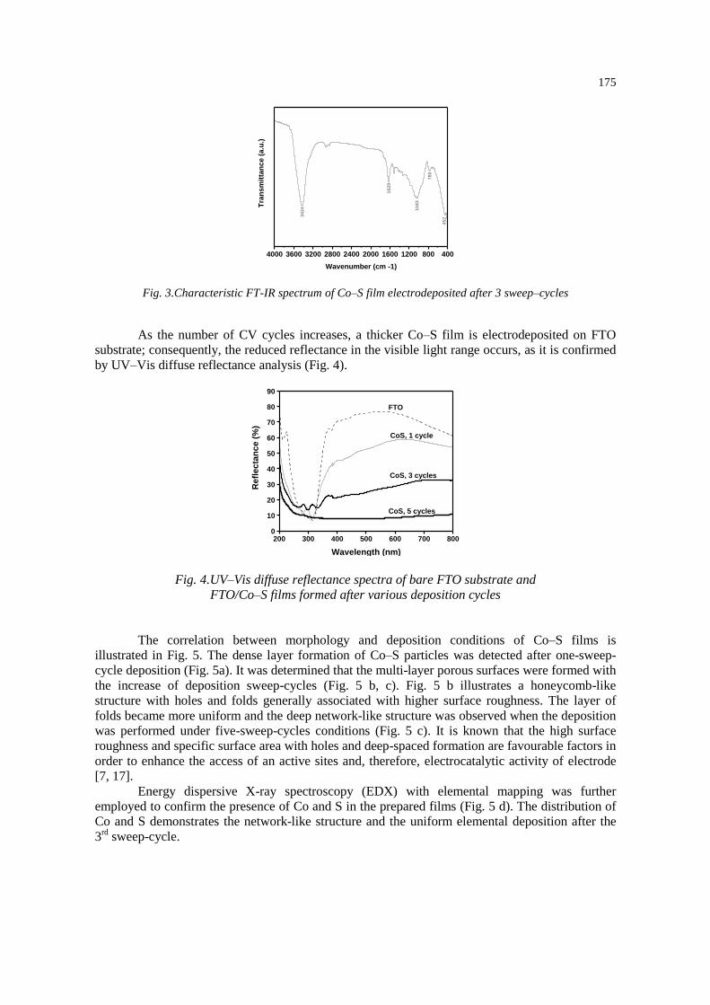
Fig. 3.Characteristic FT-IR spectrum of Co–S film electrodeposited after 3 sweep–cycles
As the number of CV cycles increases, a thicker Co–S film is electrodeposited on FTO
substrate; consequently, the reduced reflectance in the visible light range occurs, as it is confirmed
by UV–Vis diffuse reflectance analysis (Fig. 4).
Fig. 4.UV–Vis diffuse reflectance spectra of bare FTO substrate and
FTO/Co–S films formed after various deposition cycles
The correlation between morphology and deposition conditions of Co–S films is
illustrated in Fig. 5. The dense layer formation of Co–S particles was detected after one-sweep-
cycle deposition (Fig. 5a). It was determined that the multi-layer porous surfaces were formed with
the increase of deposition sweep-cycles (Fig. 5 b, c). Fig. 5 b illustrates a honeycomb-like
structure with holes and folds generally associated with higher surface roughness. The layer of
folds became more uniform and the deep network-like structure was observed when the deposition
was performed under five-sweep-cycles conditions (Fig. 5 c). It is known that the high surface
roughness and specific surface area with holes and deep-spaced formation are favourable factors in
order to enhance the access of an active sites and, therefore, electrocatalytic activity of electrode
[7, 17].
Energy dispersive X-ray spectroscopy (EDX) with elemental mapping was further
employed to confirm the presence of Co and S in the prepared films (Fig. 5 d). The distribution of
Co and S demonstrates the network-like structure and the uniform elemental deposition after the
3rd
sweep-cycle.
4000 3600 3200 2800 2400 2000 1600 1200 800 400
78
0
45
2
10
43
16
29
Tra
ns
mit
tan
ce (
a.u
.)Wavenumber (cm -1)
34
24
200 300 400 500 600 700 8000
10
20
30
40
50
60
70
80
90
CoS, 5 cycles
CoS, 3 cycles
FTO
Re
fle
cta
nc
e (
%)
Wavelength (nm)
CoS, 1 cycle

176
Fig. 5. SEM images of FTO/Co–S films after 1 (a), 3 (b) and 5 (c) deposition cycles at × 50 000
magnification and EDX elemental mapping of three-sweep-cycle Co–S film (d)
It should, however, be noted that a high content of oxygen was constantly detected in Co–
S samples and it can be explained by the next three reasons. Firstly, some amount of silica and tin
oxide from the FTO substrate was identified via EDX analysis (Fig. 6). Secondly, the
oxide/hydroxide fraction in the film, probably, derived from electrodeposition mechanism
described earlier. Usually, electrodeposited cobalt compounds are known to be covered by a native
passive film of CoO/Co(OH)2 and even undergo further oxidation to Co(III) oxidized compounds
depending on pH value of the deposition bath, the charge transfer number and applied potential
[16, 22, 26]. And finally, air exposure might be powerful oxidizer of porous Co–S film surface.
A considerable change of Co/S ratio was observed during the increase of the Co–S deposition
sweep-cycles (Table 1). For example, the ratio of Co/S was increased from 2.4/1 to 1/1 when the
deposition was varied from one to three-sweep-cycles, respectively. EDX spectra further illustrate
the elemental composition of 1, 3 and 5-sweep-cycled Co–S samples and are shown in Figure 6.
Sn and Si were detected as they originate from FTO substrate and the intensity of these
background elements tends to reduce as a result of increased number of sweep-cycles.
Table 1. EDX data of Co–S films synthesized after 1, 3 and 5 CV deposition cycles
Element Quantity (at., %)
after 1 CV
Quantity (at. %)
after 3 CV
Quantity (at. %)
after 5 CV
Cobalt 0.11 0.54 2.42
Sulphur 0.044 0.52 1.93
Oxygen 84.99 86.49 80.81
(a) (b)
(d) (c)

177
Fig. 6.EDX spectra of Co–S films prepared after 1, 3 and 5 CV deposition cycles
3.2. Electrochemical performance of Co–S films
Electrocatalytic behaviour of the FTO/Co–S electrodes were evaluated under polarization
in 1 M phosphate buffer solution. Polarization curves of bare FTO substrate and 1, 3 and 5-sweep-
cycled Co–S samples are presented in Fig. 7. A relatively low scan rate was used to utilize layered
honeycomb-like structure for charge migration in whole surface areas [26]. It can be observed that
the presence of Co–S significantly improves the catalytic behaviour of bare FTO substrate under
HER conditions and current density tends to increase with the increase in the number of deposition
sweep-cycles. The results of operando spectroscopic analysis of amorphous Co–S catalyst in
electrochemical hydrogen evolution reaction suggest that the Co–S is spontaneously transforming
into CoS2-like molecular clusters under cathodic polarization [9]. It has been estimated that Co–S
electrocatalyst can contain roughly 60% CoO and 40% CoS in the dry state and 26%CoO and 74%
CoS under HER conditions.
The collected current-potential data was used for the determination of Tafel slope b [27].
This parameter is of fundamental importance as it is an indicative parameter of the electrode
reaction mechanism. The inset of Figure 7 presents the dependence of potential as a function of
logarithm of the current density for 5 sweep-cycled electrodes. The change in the values of Tafel
slope can be considered as an indication of the change of the rate limiting step. It can be observed
that the Tafel slope values (46 and 122 mV, respectively) are in good agreement with generally
accepted Tafel slopes for HER on platinum (29, 38 or 116 mV [28]).
Fig. 7. Polarization curves of bare FTO and freshly prepared FTO/Co–S electrodes in
1.0 M phosphate buffer solution (pH 7) at a scan rate of 5mV s–1
. Inset: Tafel plot of
FTO/Co–S electrode prepared after 5 deposition cycles
0 1 2 3 4 5 6 7 8 9 10
Sn
O
Co
Si
S
Sn
CoS
after 1 CV
CoS
after 3 CV
Inte
ns
ity
(a
.u.)
Energy (keV)
CoS
after 5 CV
Co
-0.65 -0.52 -0.39 -0.26 -0.13 0.00-1.0
-0.8
-0.6
-0.4
-0.2
0.0
0.2
-0,2
-0,1
0,0
0,1
-6,0-5,0-4,0-3,0
E, V
ln|i|
b = 122 mV
b = 46 mV
i (m
A/c
m2)
E (V)
Tafel plot
FTO FTO/CoS
after 1 CV
FTO/CoS
after 3 CV
FTO/CoS
after 5 CV
178
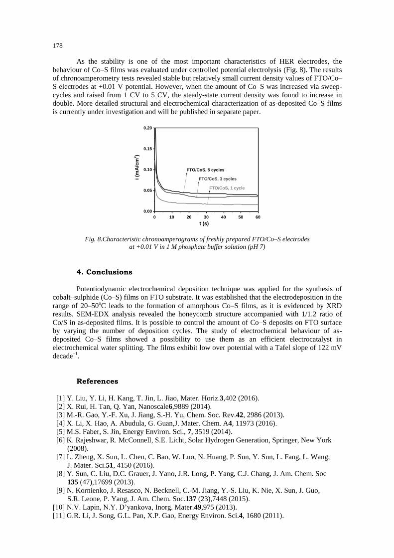
As the stability is one of the most important characteristics of HER electrodes, the
behaviour of Co–S films was evaluated under controlled potential electrolysis (Fig. 8). The results
of chronoamperometry tests revealed stable but relatively small current density values of FTO/Co–
S electrodes at +0.01 V potential. However, when the amount of Co–S was increased via sweep-
cycles and raised from 1 CV to 5 CV, the steady-state current density was found to increase in
double. More detailed structural and electrochemical characterization of as-deposited Co–S films
is currently under investigation and will be published in separate paper.
Fig. 8.Characteristic chronoamperograms of freshly prepared FTO/Co–S electrodes
at +0.01 V in 1 M phosphate buffer solution (pH 7)
4. Conclusions
Potentiodynamic electrochemical deposition technique was applied for the synthesis of
cobalt–sulphide (Co–S) films on FTO substrate. It was established that the electrodeposition in the
range of 20–50oC leads to the formation of amorphous Co–S films, as it is evidenced by XRD
results. SEM-EDX analysis revealed the honeycomb structure accompanied with 1/1.2 ratio of
Co/S in as-deposited films. It is possible to control the amount of Co–S deposits on FTO surface
by varying the number of deposition cycles. The study of electrochemical behaviour of as-
deposited Co–S films showed a possibility to use them as an efficient electrocatalyst in
electrochemical water splitting. The films exhibit low over potential with a Tafel slope of 122 mV
decade–1
.
References
[1] Y. Liu, Y. Li, H. Kang, T. Jin, L. Jiao, Mater. Horiz.3,402 (2016).
[2] X. Rui, H. Tan, Q. Yan, Nanoscale6,9889 (2014).
[3] M.-R. Gao, Y.-F. Xu, J. Jiang, S.-H. Yu, Chem. Soc. Rev.42, 2986 (2013).
[4] X. Li, X. Hao, A. Abudula, G. Guan,J. Mater. Chem. A4, 11973 (2016).
[5] M.S. Faber, S. Jin, Energy Environ. Sci., 7, 3519 (2014).
[6] K. Rajeshwar, R. McConnell, S.E. Licht, Solar Hydrogen Generation, Springer, New York
(2008).
[7] L. Zheng, X. Sun, L. Chen, C. Bao, W. Luo, N. Huang, P. Sun, Y. Sun, L. Fang, L. Wang,
J. Mater. Sci.51, 4150 (2016).
[8] Y. Sun, C. Liu, D.C. Grauer, J. Yano, J.R. Long, P. Yang, C.J. Chang, J. Am. Chem. Soc
135 (47),17699 (2013).
[9] N. Kornienko, J. Resasco, N. Becknell, C.-M. Jiang, Y.-S. Liu, K. Nie, X. Sun, J. Guo,
S.R. Leone, P. Yang, J. Am. Chem. Soc.137 (23),7448 (2015).
[10] N.V. Lapin, N.Y. D’yankova, Inorg. Mater.49,975 (2013).
[11] G.R. Li, J. Song, G.L. Pan, X.P. Gao, Energy Environ. Sci.4, 1680 (2011).
0 10 20 30 40 50 60
0.20
0.15
0.10
0.05
0.00
i (m
A/c
m2)
t (s)
FTO/CoS, 1 cycle
FTO/CoS, 3 cycles
FTO/CoS, 5 cycles

179
[12] E.J. Popczun, J.R. McKone, C.G. Read, A.J. Biacchi, A.M. Wiltrout, N.S. Lewis,
R.E. Schaak, J. Am. Chem. Soc.135(25),9267 (2013).
[13] M. Wang, A.M. Anghel, B. Marsan, N.-L. Cevey Ha, N. Pootrakulchote, S.M. Zakeeruddin,
M. Grätzel, J. Am. Chem. Soc.131 (44), 15976 (2009).
[14] S.K. Swami, N. Chaturvedi, A. Kumar, R. Kapoor, V. Dutta, J. Frey, T. Moehl, M. Grätzel
S. Mathew, M.K. Nazeeruddin, J. Power Sources, 275, 80 (2015).
[15] J.Y. Lin, J.H. Liao, T.C. Wei, Electrochem. Solid-State Lett. 14, D41 (2011).
[16] J.Y. Lin, J.H. Liao, S.W. Chou, Electrochim. Acta 56, 8818 (2011).
[17] J. Huo, M. Zheng, Y. Tu, J. Wu, L. Hu, S. Dai, Electrochim. Acta, 159,166 (2015).
[18] H.-J. Kim, S.-W. Kim, C.V.V.M. Gopi, S.-K. Kim, S.S. Rao, M.-S. Jeong, J. Power Sources
268,163 (2014).
[19] Y. Shengyuan, A.S. Nair, Z. Peining, S. Ramakrishna, Mater. Lett.76,43 (2012).
[20] J. Huo, J. Wu, M. Zheng, Y. Tu, Z. Lan, Electrochim. Acta180, 574 (2015).
[21] J.S. Santos, R. Matos, F. Trivinho-Strixino, E.C. Pereira, Electrochim. Acta53, 644 (2007).
[22] W.A. Badawy, F.M. Al-Kharafi, J.R. Al-Ajmi, J. Appl. Electrochem.30,693 (2000).
[23] K. Nakamoto, Infrared and Raman Spectra of Inorganic and Coordination Compounds. Part
A: Theory and Applications in Inorganic Chemistry,Wiley-Interscience, New York, 5th edn
(1997).
[24] G. Rajadurai, A. Puhal Raj, S. Pari, Arch. Phy. Res. 4, 61 (2013).
[25] V. Kumar, R. Sundararajan, J. Miner. Mater. Charact. Eng.3,118 (2015).
[26] R.S. Ray, B. Sarma, A.L. Jurovitzki, M. Misra, Chem. Eng. J.260, 671 (2015).
[27] J.M. Falkowski, Y. Surendranath, ACS Catal.5 (6),341 (2015).
[28] J.O.M. Bockris, E.C. Potter, J. Electrochem. Soc.99 (4), 169 (1952).