Structural Steelwork Eurocodes Development of A …...Structural Steelwork Eurocodes – Development...
92
©SSEDTA 2001 Structural Steelwork Eurocodes Development of A Trans-national Approach Course: Eurocode 3 Module 7 : Worked Examples Lecture 20 : Simple braced frame Contents: 1. Simple Braced Frame 1.1 Characteristic Loads 1.2 Design Loads F d = γ F F k 1.3 Partial Safety Factors for Strength 2. Floor Beam - Fully Restrained 2.1 Classification of Cross-section 2.1.1Flange buckling 2.1.2 Web buckling 2.2 Shear on Web 2.3 Deflection Check 2.4 Additional Checks if Section is on Seating Cleats 2.5 Crushing Resistance 2.6 Crippling Resistance 2.7 Buckling Resistance 2.8 Summary 3. Roof Beam – Restrained at Load Points 3.1 Initial Section Selection 3.2 Classification of Cross Section 3.2.1 Flange buckling 3.2.2 Web buckling 3.3 Design Buckling Resistance Moment 3.4 Shear on Web 3.5 Deflection Check 3.6 Crushing, Crippling and Buckling 3.7 Summary 4. Internal Column 4.1 Loadings 4.2 Section properties
Transcript of Structural Steelwork Eurocodes Development of A …...Structural Steelwork Eurocodes – Development...
©SSEDTA 2001
Structural Steelwork Eurocodes Development of
A Trans-national Approach Course: Eurocode 3 Module 7 : Worked Examples Lecture 20 : Simple braced frame
Contents: 1. Simple Braced Frame
1.1 Characteristic Loads 1.2 Design Loads Fd = γF Fk 1.3 Partial Safety Factors for Strength
2. Floor Beam - Fully Restrained 2.1 Classification of Cross-section 2.1.1Flange buckling 2.1.2 Web buckling 2.2 Shear on Web 2.3 Deflection Check 2.4 Additional Checks if Section is on Seating Cleats 2.5 Crushing Resistance 2.6 Crippling Resistance 2.7 Buckling Resistance 2.8 Summary 3. Roof Beam – Restrained at Load Points 3.1 Initial Section Selection 3.2 Classification of Cross Section 3.2.1 Flange buckling 3.2.2 Web buckling 3.3 Design Buckling Resistance Moment 3.4 Shear on Web 3.5 Deflection Check 3.6 Crushing, Crippling and Buckling 3.7 Summary 4. Internal Column 4.1 Loadings 4.2 Section properties
Structural Steelwork Eurocodes – Development of a Trans-National Approach Worked examples Design of a 3-storey unbraced frame
23/02/07 2
4.3 Classification of Cross-Section 4.3.1 Flange (subject to compression) 4.3.2 Web (subject to compression) 4.4 Resistance of Cross-Section 4.5 Buckling Resistance of Member 4.6 Determination of Reduction Factor χy 4.7 Determination of Reduction Factor χz 5. External Column 5.1 Loadings 5.2 Section properties 5.3 Classifcation of Cross-Section 5.3.1 Flange (subject to compression) 5.3.2 Web (subject to compression) 5.4 Resistance of Cross-Section 5.5 Buckling Resistance of Member 5.6 Determination of Reduction factor χy 5.7 Determination of Reduction factor χz 6. Design of Cross-Bracing 6.1 Section Properties 6.2 Classification of Cross-Section 6.3 Design of Compression Member 6.3.1 Resistance of Cross-section 6.3.2 Design Buckling Resistance 6.3.3 Determination of Reduction Factor χ? 6.4 Design of Tension Member 6.4.1Resistance of Cross-Section 7. Concluding Summary
Structural Steelwork Eurocodes – Development of a Trans-National Approach Worked examples Design of a 3-storey unbraced frame
23/02/07 3
1. Simple Braced Frame
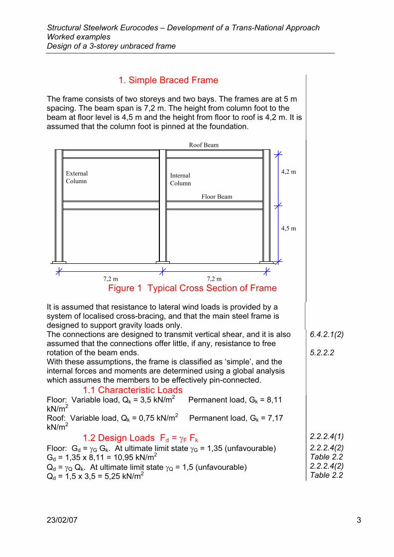
The frame consists of two storeys and two bays. The frames are at 5 m spacing. The beam span is 7,2 m. The height from column foot to the beam at floor level is 4,5 m and the height from floor to roof is 4,2 m. It is assumed that the column foot is pinned at the foundation.
7,2 m
4,2 m
4,5 m
7,2 m
Roof Beam
Floor Beam
InternalColumn
ExternalColumn
Figure 1 Typical Cross Section of Frame
It is assumed that resistance to lateral wind loads is provided by a system of localised cross-bracing, and that the main steel frame is designed to support gravity loads only.
The connections are designed to transmit vertical shear, and it is also assumed that the connections offer little, if any, resistance to free rotation of the beam ends. With these assumptions, the frame is classified as ‘simple’, and the internal forces and moments are determined using a global analysis which assumes the members to be effectively pin-connected.
6.4.2.1(2) 5.2.2.2
1.1 Characteristic Loads Floor: Variable load, Qk = 3,5 kN/m2 Permanent load, Gk = 8,11 kN/m2
Roof: Variable load, Qk = 0,75 kN/m2 Permanent load, Gk = 7,17 kN/m2
1.2 Design Loads Fd = γF Fk 2.2.2.4(1) Floor: Gd = γG Gk. At ultimate limit state γG = 1,35 (unfavourable) Gd = 1,35 x 8,11 = 10,95 kN/m2 Qd = γQ Qk. At ultimate limit state γQ = 1,5 (unfavourable) Qd = 1,5 x 3,5 = 5,25 kN/m2
2.2.2.4(2) Table 2.2 2.2.2.4(2) Table 2.2
Structural Steelwork Eurocodes – Development of a Trans-National Approach Worked examples Design of a 3-storey unbraced frame
23/02/07 4
Roof: Gd = γG Gk. At ultimate limit state γG = 1,35 (unfavourable) Gd = 1,35 x 7,17 = 9,68 kN/m2 Qd = γQ Qk. At ultimate limit state γQ = 1,5 (unfavourable) Qd = 1,5 x 0,75 = 1,125 kN/m2
2.2.2.4(2) Table 2.2 2.2.2.4(2) Table 2.2
The steel grade selected for beams, columns and joints is Fe360. (fy = 235 N/mm2)
Table 3.1
1.3 Partial Safety Factors for Strength The following partial safety factors for strength have been adopted during the design: • Resistance of Class 1,2 or 3 cross-section, γM0 = 1,1 • Resistance of member to buckling, γM1 = 1,1 • Resistance of bolted connections, γMb = 1,25
2.3.3.2(1) 5.1.1(2) 5.1.1(2) 6.1.1(2)
The following load case, corresponding to permanent and variable actions (no horizontal loads) is found to be critical.
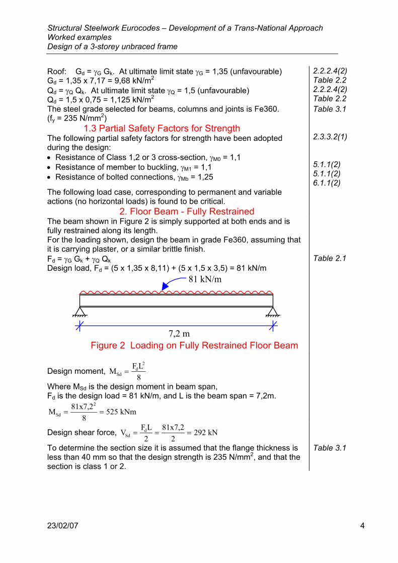
2. Floor Beam - Fully Restrained The beam shown in Figure 2 is simply supported at both ends and is fully restrained along its length. For the loading shown, design the beam in grade Fe360, assuming that it is carrying plaster, or a similar brittle finish.
Fd = γG Gk + γQ Qk Design load, Fd = (5 x 1,35 x 8,11) + (5 x 1,5 x 3,5) = 81 kN/m
Table 2.1
7,2 m
81 kN/m
Figure 2 Loading on Fully Restrained Floor Beam
Design moment, M F L8Sd
d2
=
Where MSd is the design moment in beam span, Fd is the design load = 81 kN/m, and L is the beam span = 7,2m.
M 81x7,28
525 kNmSd
2
= =
Design shear force, V F L2
81x7,22
292 kNSdd= = =
To determine the section size it is assumed that the flange thickness is less than 40 mm so that the design strength is 235 N/mm2, and that the section is class 1 or 2.
Table 3.1
Structural Steelwork Eurocodes – Development of a Trans-National Approach Worked examples Design of a 3-storey unbraced frame
23/02/07 5
The design bending moment, MSd, must be less than or equal to the design moment resistance of the cross section, Mc.Rd: MSd ≤ Mc.Rd
Mc.Rd = Mpl.y.Rd =W fpl y
M0γ
Where Wpl is the plastic section modulus (to be determined), fy is the yield strength = 235 N/mm2, and γM0 is the partial material safety factor = 1,1.
5.4.5.1(1) Table 3.1 5.1.1(2)
Therefore, rearranging:
W Mf
525x10 x1,1235
2457 cmpl.requiredsd M0
y
33= = =
γ
Try IPE 550 Section properties: Depth, h = 550 mm, Width, b = 210 mm Web thickness, tw = 11,1 mm Flange thickness, tf = 17,2 mm Plastic modulus, Wpl = 2787 cm3
5.4.5.1
This notation conforms with Figure 1.1 in Eurocode 3: Part1.1. 2.1 Classification of Cross-section
As a simply supported beam is not required to have any plastic rotation capacity (only one hinge required), it is sufficient to ensure that the section is at least class 2 to develop the plastic moment resistance.
5.3 5.3.2 and Table 5.3.1
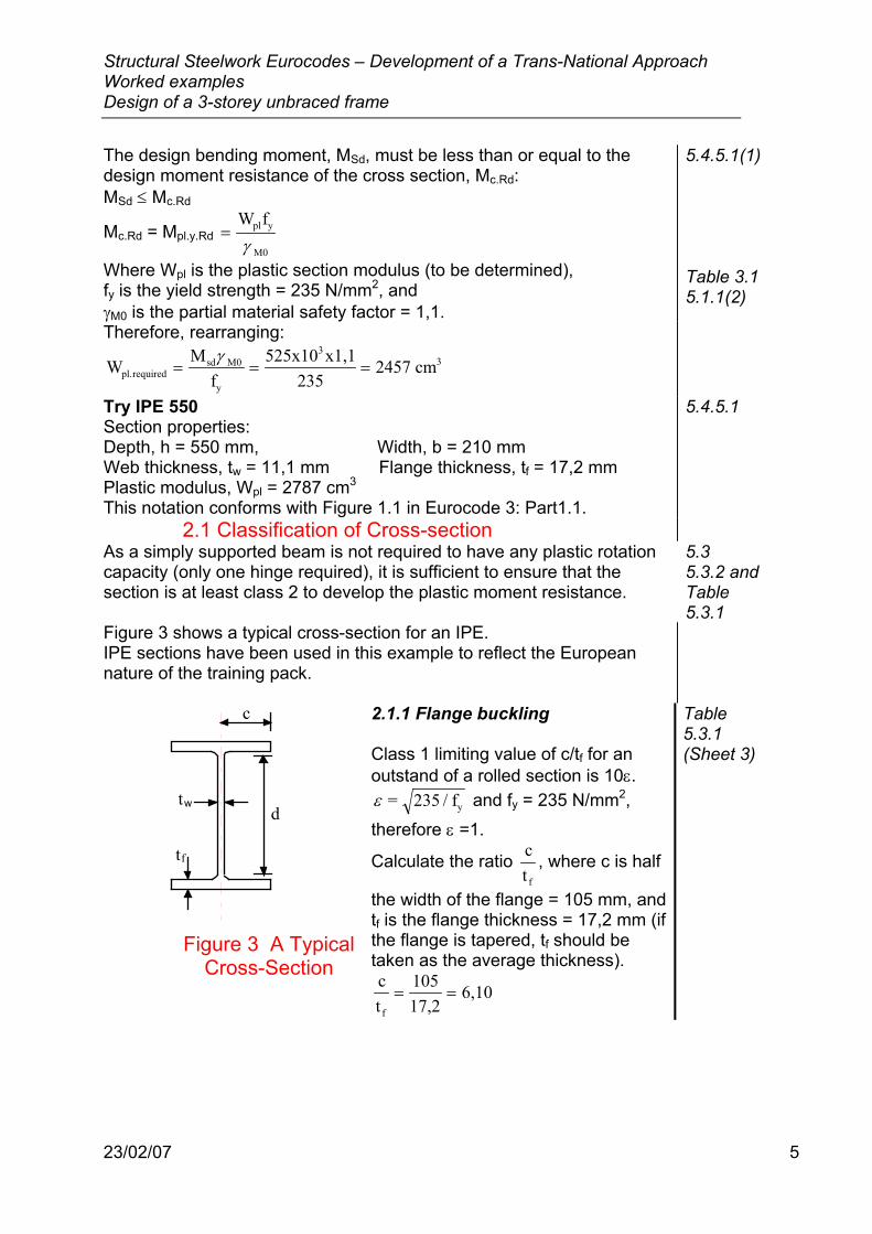
Figure 3 shows a typical cross-section for an IPE. IPE sections have been used in this example to reflect the European nature of the training pack.
tw
t
d
c
f
Figure 3 A Typical
Cross-Section
2.1.1 Flange buckling Class 1 limiting value of c/tf for an outstand of a rolled section is 10ε. ε = 235 / fy and fy = 235 N/mm2,
therefore ε =1.
Calculate the ratio ct f
, where c is half
the width of the flange = 105 mm, and tf is the flange thickness = 17,2 mm (if the flange is tapered, tf should be taken as the average thickness). ct
10517,2
6,10f
= =
Table 5.3.1 (Sheet 3)
Structural Steelwork Eurocodes – Development of a Trans-National Approach Worked examples Design of a 3-storey unbraced frame
23/02/07 6
2.1.2 Web buckling Class 1 limiting value of d/tw for a web subject to bending is 72ε. ε = 235 / fy and fy = 235 N/mm2, therefore ε =1.
Calculate the ratio dtw
, where d is the depth between root radii = 467,6
mm and tw is the web thickness = 11,1 mm. dt
467,611,1
42,1w
= =
ct
10f
< ε and dt
72w
< ε
∴ Section is Class 1 and is capable of developing plastic moment.
Table 5.3.1 (Sheet 1) Table 5.3.1 (Sheets 1 and 3)
2.2 Shear on Web The shear resistance of the web must be checked. The design shear force, VSd, must be less than or equal to the design plastic shear resistance, Vpl.Rd: VSd ≤ Vpl.Rd
Where Vpl.Rd is given by Af / 3
vy
M0γ
5.4.6
For rolled I and H sections loaded parallel to the web, Shear area, Av = 1,04 h tw, fy is the yield strength = 235 N/mm2, and γM0 is the partial material safety factor = 1,1.
5.4.6(4) Table 3.1 5.1.1(2)
∴ =V1,04ht f
3xpl.Rdw y
M0γ = =
1,04 x 550 x 11,1 x 2353 x 1,1x10
783 kN3
This is greater than the shear on the section (292 kN). The shear on the beam web is OK.
If the beam has partial depth end-plates, a local shear check is required on the web of the beam where it is welded to the end-plate.
V Af / 3
pl.Rd vy
M0
=γ
where Av = twd, and d is the depth of end-plate = (for example) 300 mm.
V 11,1 x 300 x 2353 x 1,1 x 10
411 kNpl.Rd 3= =
This is greater than the shear on the section (292 kN). The local shear on the beam web is OK.
Structural Steelwork Eurocodes – Development of a Trans-National Approach Worked examples Design of a 3-storey unbraced frame
23/02/07 7
Other simple joints may be used instead, e.g. web cleat joints or fin plate joints.
A further check is sometimes required, especially when there are significant point loads, cantilevers or continuity, to ensure that the shear will not have a significant effect on the moment resistance. This check is carried out for the moment and shear at the same point. The moment resistance of the web is reduced if the shear is more than 50% of the shear resistance of the section. With a uniform load, the maximum moment and shear are not coincident and this check is not required for beams without web openings.
5.4.7(3)
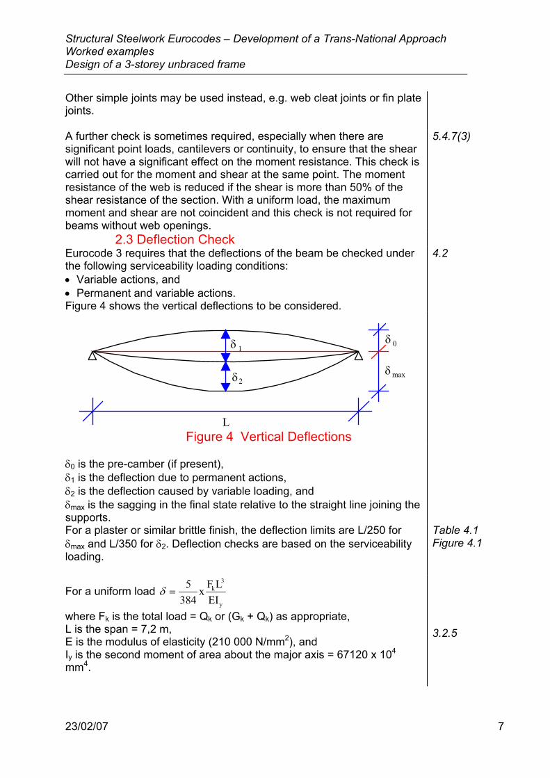
2.3 Deflection Check Eurocode 3 requires that the deflections of the beam be checked under the following serviceability loading conditions: • Variable actions, and • Permanent and variable actions. Figure 4 shows the vertical deflections to be considered.
4.2
δ
δδ
δ
L
0
max
1
2
Figure 4 Vertical Deflections
δ0 is the pre-camber (if present), δ1 is the deflection due to permanent actions, δ2 is the deflection caused by variable loading, and δmax is the sagging in the final state relative to the straight line joining the supports.
For a plaster or similar brittle finish, the deflection limits are L/250 for δmax and L/350 for δ2. Deflection checks are based on the serviceability loading.
Table 4.1 Figure 4.1
For a uniform load δ =5
384x F L
EIk
3
y
where Fk is the total load = Qk or (Gk + Qk) as appropriate, L is the span = 7,2 m, E is the modulus of elasticity (210 000 N/mm2), and Iy is the second moment of area about the major axis = 67120 x 104 mm4.
3.2.5
Structural Steelwork Eurocodes – Development of a Trans-National Approach Worked examples Design of a 3-storey unbraced frame
23/02/07 8
For permanent actions, Fk = 5 x 8,11 x 7,2 = 292 kN. Therefore, deflection due to permanent actions,
δ 1 = =5 x 292x10 x 7200
384 x 210 000 x 67120x1010,1 mm
3 3
4
For variable actions, Fk = 5 x 3,5 x 7,2 = 126 kN. Therefore, deflection due to variable actions,
δ 2 = =5 x 126x10 x 7200
384 x 210 000 x 67120x104,3 mm
3 3
4
The maximum deflection, δ δ δmax 1 2+ = 10,1+ 4,3 = 14,4 mm=
Deflection limit for δ 2L
3507200350
20,6 mm= = =
The actual deflection is less than the allowable deflection: 4,3 mm < 20,6 mm
Deflection limit for δ maxL
2507200250
28,8 mm= = =
The actual deflection is less than the allowable deflection: 14,4 mm < 28,8 mm ∴ OK.
Table 4.1 Table 4.1
The calculated deflections are less than the limits, so no pre-camber is required. It should be noted that if the structure is open to the public, there is a limit of 28 mm for the total deflection of δ1 + δ2 (neglecting any pre-camber) under the frequent combination, to control vibration. This is based on a single degree of freedom, lumped mass approach. For the frequent combination the variable action is multiplied by ψ, which has a value of 0,6 for offices.
4.3.2(2) Lecture 3, section 6.2 2.3.4(2)
2.4 Additional Checks if Section is on Seating Cleats There are cases where the beams may be supported on seating cleats, or on other materials such as concrete pads. A similar situation arises when a beam supports a concentrated load applied through the flanges. In these cases the following checks are required: • Crushing of the web • Crippling of the web • Buckling of the web Generally, these checks need only be carried out for short beams or beams with concentrated loads. For the sake of completeness, these checks are included in this worked example.
5.7.3 5.7.4 5.7.5
The following detailed checks are for an 85 mm stiff bearing. (The actual length of stiff bearing will depend on the detail of the connection - see Figure 5.7.2)
Structural Steelwork Eurocodes – Development of a Trans-National Approach Worked examples Design of a 3-storey unbraced frame
23/02/07 9
2.5 Crushing Resistance 5.7.3 The crushing resistance is given by
R(s s )t f
y.Rds y w yw
M1
=+
γ
where ss is the length of stiff bearing = 85 mm, tw is the web thickness = 11,1 mm, fyw is the yield strength of the web = 235 N/mm2, γM1 is the partial material safety factor for buckling resistance = 1,1, and sy is the length over which the effect takes place, based on the section geometry and the longitudinal stresses in the flange.
Table 3.1 5.1.1(2) 5.7.3(1)
sy = 2tf (bf/tw)0,5 (fyf/fyw)0,5 [1 - (σf.Ed /fyf)2 ]0,5
At the support, the stress in the beam flange, σf.Ed, is zero, fyf = fyw but the value of sy is halved at the end of the member.
5.7.3(3)
s 2 x 17,2 x (210 / 11,1)2
75 mmy
0,5
= =
∴ Crushing resistance, Ry.Rd =+
=(85 75) x 11,1 x 235
1,1x10379,4 kN3
This is greater than the reaction (292 kN). The crushing resistance is OK
2.6 Crippling Resistance The crippling resistance is given by
R0,5t (Ef ) [(t / t ) 3(t / t )(s / d)]
a.Rdw
2yw
0,5f w
0,5w f s
M1
=+
γ
where tw is the thickness of the web = 11,1 mm, E is the modulus of elasticity = 210 000 N/mm2, fyw is the yield strength of the web = 235 N/mm2, tf is the flange thickness = 17,2 mm, ss is the length of stiff bearing = 85 mm, but ss is limited to a maximum of 0,2d (467,6 mm x 0,2 = 93,5 mm), d is the depth between root radii = 467,6 mm, and γM1 is the partial material safety factor buckling resistance = 1,1.
R 0,5 x 11,1 (210000 x 235) [(17,2 / 11,1) 3(11,1 / 17,2)(85 / 467,6)]1,1x10a,Rd
2 0,5 0,5
3=+
= 626 kN This is greater than the reaction (292 kN). The crippling resistance is OK.
5.7.4(1) 3.2.5 Table 3.1 5.7.4(1) 5.1.1(2)
Structural Steelwork Eurocodes – Development of a Trans-National Approach Worked examples Design of a 3-storey unbraced frame
23/02/07 10
2.7 Buckling Resistance The buckling resistance is determined by taking a length of web as a strut. The length of web is taken from Eurocode 3, which in this case, gives a length:
b 0,5(h s ) a s2eff
2s2 0,5 s= + + + but ≤ [h2 + ss
2]0,5
where h is the height of the section = 550 mm, ss is the length of stiff bearing = 85 mm, and a is the distance to the end of the beam = 0 mm.
b 0,5(550 85 ) 852
320,5 mmeff2 2 0,5= + + =
5.7.5 Figure 5.7.3
Provided that the construction is such that the top flange is held by a slab and the bottom by seating cleats, against rotation and displacement, the effective height of the web for buckling should be taken as 0,7 x distance between fillets. l = 467,6 mm x 0,7 = 327 mm
Radius of gyration for web, i t12
11,112
w= = = 3 2,
Slenderness of the web, λ = = =li
3273,2
102
Non-dimensional slenderness of the web, λλλ
β=1
A0,5
Where λ1 = 93,9 ε = 93,9 x 1 = 93,9, and βA = 1
∴ = = Non - dimensional slenderness of the web, λ 10293 9
1 09,
,
Using buckling curve c, the value of the reduction factor, χ may be determined from Table 5.5.2. Reduction factor, χ = 0,49
Buckling resistance of a compression member, NAf
b.RdA y
M1
=χβ
γ
A is the cross-sectional area = beff tw, fy is the yield strength = 235 N/mm2, and γM1 is the partial material safety factor for buckling resistance = 1,1.
N 0,49 x 1 x 320,5 x 11,1 x 2351,1x10
372,4 kNb.Rd 3= =
This is greater than the reaction (292 kN). The buckling resistance is OK.
5.7.5(4) 5.5.1.4(3) 5.5.1.2 5.7.5(3) 5.7.5(3) and Table 5.5.2 5.5.1.1(1) Table 3.1 5.1.1(2)
2.8 Summary The trial section IPE 550 is satisfactory if the section is on a stiff bearing 85 mm long. If it is supported by web cleats or welded end plates, the web checks, except for shear, are not required and the section is again satisfactory. The beam is satisfactory.
Structural Steelwork Eurocodes – Development of a Trans-National Approach Worked examples Design of a 3-storey unbraced frame
23/02/07 11
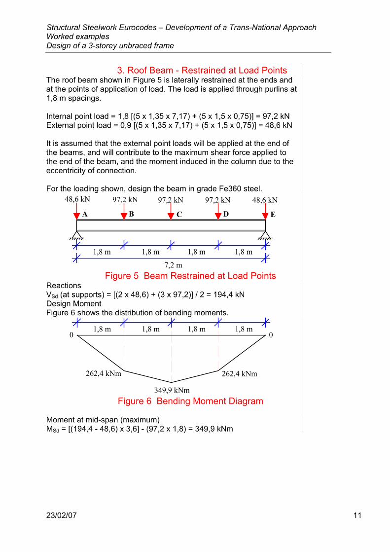
3. Roof Beam - Restrained at Load Points The roof beam shown in Figure 5 is laterally restrained at the ends and at the points of application of load. The load is applied through purlins at 1,8 m spacings. Internal point load = 1,8 [(5 x 1,35 x 7,17) + (5 x 1,5 x 0,75)] = 97,2 kN External point load = 0,9 [(5 x 1,35 x 7,17) + (5 x 1,5 x 0,75)] = 48,6 kN It is assumed that the external point loads will be applied at the end of the beams, and will contribute to the maximum shear force applied to the end of the beam, and the moment induced in the column due to the eccentricity of connection. For the loading shown, design the beam in grade Fe360 steel.
7,2 m
48,6 kN 48,6 kN97,2 kN 97,2 kN 97,2 kN
1,8 m 1,8 m 1,8 m 1,8 m
A B C D E
Figure 5 Beam Restrained at Load Points
Reactions VSd (at supports) = [(2 x 48,6) + (3 x 97,2)] / 2 = 194,4 kN
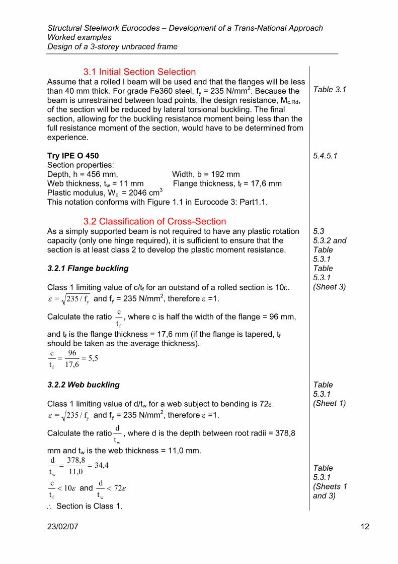
Design Moment Figure 6 shows the distribution of bending moments.
1,8 m 1,8 m 1,8 m 1,8 m0 0
262,4 kNm 262,4 kNm
349,9 kNm Figure 6 Bending Moment Diagram
Moment at mid-span (maximum) MSd = [(194,4 - 48,6) x 3,6] - (97,2 x 1,8) = 349,9 kNm
Structural Steelwork Eurocodes – Development of a Trans-National Approach Worked examples Design of a 3-storey unbraced frame
23/02/07 12
3.1 Initial Section Selection Assume that a rolled I beam will be used and that the flanges will be less than 40 mm thick. For grade Fe360 steel, fy = 235 N/mm2. Because the beam is unrestrained between load points, the design resistance, Mc.Rd, of the section will be reduced by lateral torsional buckling. The final section, allowing for the buckling resistance moment being less than the full resistance moment of the section, would have to be determined from experience.
Table 3.1
Try IPE O 450 Section properties: Depth, h = 456 mm, Width, b = 192 mm Web thickness, tw = 11 mm Flange thickness, tf = 17,6 mm Plastic modulus, Wpl = 2046 cm3
5.4.5.1
This notation conforms with Figure 1.1 in Eurocode 3: Part1.1.
3.2 Classification of Cross-Section As a simply supported beam is not required to have any plastic rotation capacity (only one hinge required), it is sufficient to ensure that the section is at least class 2 to develop the plastic moment resistance.
5.3 5.3.2 and Table 5.3.1
3.2.1 Flange buckling Class 1 limiting value of c/tf for an outstand of a rolled section is 10ε. ε = 235 / fy and fy = 235 N/mm2, therefore ε =1.
Calculate the ratio ct f
, where c is half the width of the flange = 96 mm,
and tf is the flange thickness = 17,6 mm (if the flange is tapered, tf should be taken as the average thickness). ct
9617,6
5,5f
= =
Table 5.3.1 (Sheet 3)
3.2.2 Web buckling Class 1 limiting value of d/tw for a web subject to bending is 72ε. ε = 235 / fy and fy = 235 N/mm2, therefore ε =1.
Calculate the ratio dtw
, where d is the depth between root radii = 378,8
mm and tw is the web thickness = 11,0 mm. dt
378,811,0
34,4w
= =
ct
10f
< ε and dt
72w
< ε
∴ Section is Class 1.
Table 5.3.1 (Sheet 1) Table 5.3.1 (Sheets 1 and 3)
Structural Steelwork Eurocodes – Development of a Trans-National Approach Worked examples Design of a 3-storey unbraced frame
23/02/07 13
3.3 Design Buckling Resistance Moment The design buckling resistance moment of a laterally unrestrained beam is given by:
M =W f
b.RdLT W pl.y y
M1
χ βγ
in which χLT is the reduction factor for lateral torsional buckling, from Table 5.5.2, for the appropriate value of λ LT , using curve a for rolled sections.
5.5.2 Table 5.5.2 5.5.2(4)
In this case full lateral restraint is provided at the supports and at the load points B, C and D. In general, all segments need to be checked, but in this case they are all of equal length. The segments B - C and C - D are subject to the most severe condition, but with symmetrical loading only one segment needs to be checked.
Segment B - C The value of λLT can be determined using Annex F. For segment B - C it is assumed that the purlins at B and C provide the following conditions: • restraint against lateral movement, • restraint against rotation about the longitudinal axis (i.e. torsional/twisting restraint), and • freedom to rotate in plan. i.e. k = kw = 1,0
Annex F F.1.2(2)
For this example, the general formula for λLT has been used, as the section is doubly symmetric and end-moment loading is present.
The following formula for λLT may be used:
( )λ LT
LT
1LT
L / i
CL / a
=
+
0 52 0 25
125 66
,
,
,
where L is the length between B and C = 1800 mm, Iz is the second moment of area about the z - z axis = 2085 x 104 mm4, Iw is the warping constant = 998 x 109 mm6, Wpl.y is the plastic modulus about the y - y axis = 2046 x 103 mm3, and It is the torsion constant = 89,3 x 104 mm4.
Equation F.15
i I IW
2085x10 x 998x10(2046x10 )
47,2 mmLTz w
pl.y2
0,254 9
3 2
0,25
=
=
=
F.2.2(3)
a II
998x10109x10
957 mmLTw
t
0,5 9
4
0,5
=
=
=
F.2.2(1)
Structural Steelwork Eurocodes – Development of a Trans-National Approach Worked examples Design of a 3-storey unbraced frame
23/02/07 14
Note: These properties will probably be tabulated in handbooks. See also appendix A at the end of this example.
C1 is the correction factor for the effects of any change of moment along the length, L. ψ = 262,4/349,9 = 0,75, k = 1, therefore C1 = 1,141
Table F.1.1
Substituting into the above equation:
( )λ LT =
+
=1800 47 2
1141 11800 957
25 66
34 60 5
2 0 25/ ,
,/,
,,
,
Non-dimensional slenderness, λλλ
βLTLT
1w
0,5=
Where λ1 = 93,9 ε = 93,9 x 1 = 93,9, βw = 1 for class 1 sections.
Therefore, λ LT0,5= =
34 693 9
1 0 0 37,,
( , ) ,
5.5.2(4) 5.5.2(5)
For rolled I sections, buckling curve a should be used. From Table 5.5.2, the reduction factor, χLT = 0,96. (This represents a 4% strength reduction due to moment)
Table 5.5.3 Table 5.5.2
Wpl.y is the plastic modulus about the y - y axis = 2046 x 103 mm3, fy is the yield strength of the steel = 235 N/mm2, and γM1 is the partial material safety factor for buckling resistance = 1,1.
Table 3.1 5.1.1(2)
The design buckling resistance moment for segment B - C is:
M =W f x 1 x 2046x10 x 235
1,1 x 10 kNmb.Rd
LT W pl.y y
M1
3
6
χ βγ
= =0 96 419 6, ,
5.5.2
Mb.Rd = 419,6 kNm > MSd = 349,9 kNm, therefore the section is satisfactory.

Structural Steelwork Eurocodes – Development of a Trans-National Approach Worked examples Design of a 3-storey unbraced frame
23/02/07 15
3.4 Shear on Web The maximum shear occurs at the supports, VSd = 194,4 kN. The design shear resistance for a rolled I section is:
( )V
1,04ht fpl.Rd
w y
M0
=/ 3
γ
where h is the height of the section = 456 mm, tw is the web thickness = 11 mm, fy is the yield strength of the steel = 235 N/mm2, and γM0 is the partial material safety factor for the resistance of the cross-section = 1,1.
V 1,04 x 456 x 11 x 235 x 1,1 x 10
643 kNpl.Rd 3= =3
VSd = 194,4 kN < Vpl.Rd = 643 kN, therefore the section is satisfactory.
5.4.6(1) 5.4.6(4) Table 3.1 5.1.1(2)
Inspection shows that VSd < (Vpl.Rd / 2), so there is no reduction in moment resistance due to the shear in the web.
5.4.7(2)
3.5 Deflection Check Eurocode 3 requires that the deflections of the beam be checked under the following serviceability loading conditions: • Variable actions, and • Permanent and variable actions.
4.2
For a general roof, the deflection limits are L/200 for δmax and L/250 for δ2. Deflection checks are based on the serviceability loading.
Table 4.1 Figure 4.1
Consider the deflection from the permanent loading. For a point load, distance a from the end of the beam:
Central deflection, δ = −
F aEI
L16
a12
k
y
2 2
where Fk is the value of one point load = (7,17 x 5 x 1,8) = 64,5 kN, E is the modulus of elasticity = 210 000 N/mm2, Iy is the second moment of area about the major axis = 40920 x 104 mm4, L is the span of the beam = 7,2 m, and a is the distance from the support to the adjacent load = 1,8 m.
Central deflection, δ = −
=
64,5x10 x 1800210 000 x 40920x10
7200 180012
mm3
4
2 2
164 0,
3.2.5(1)
Structural Steelwork Eurocodes – Development of a Trans-National Approach Worked examples Design of a 3-storey unbraced frame
23/02/07 16
For a central point load:
Central deflection, δ =F L
48EIk
3
y
where Fk is the value of one point load = (7,17 x 5 x 1,8) = 64,5 kN, L is the span of the beam = 7,2 m, E is the modulus of elasticity = 210 000 N/mm2, and Iy is the second moment of area about the major axis = 40920 x 104 mm4.
Central deflection, δ = =64,5x10 x 7200
48 x 210 000 x 40920x10 mm
3 3
4 5 8,
3.2.5(1)
Total deflection due to permanent loading, δ1 = 5,8 + (2 x 4,0) = 13,8 mm
Consider the deflection from the variable loading.
For a point load, distance a from the end of the beam:
Central deflection, δ = −
F aEI
L16
a12
k
y
2 2
where Fk is the value of one point load = (0,75 x 5 x 1,8) = 6,75 kN, E is the modulus of elasticity = 210 000 N/mm2, Iy is the second moment of area about the major axis = 40920 x 104 mm4, L is the span of the beam = 7,2 m, and a is the distance from the support to the adjacent load = 1,8 m.
Central deflection, δ = −
=
6,75x10 x 1800210 000 x 40920x10
7200 180012
mm3
4
2 2
160 4,
3.2.5(1)
For a central point load:
Central deflection, δ =F L
48EIk
3
y
where Fk is the value of one point load = (0,75 x 5 x 1,8) = 6,75 kN, L is the span of the beam = 7,2 m, E is the modulus of elasticity = 210 000 N/mm2, and Iy is the second moment of area about the major axis = 40920 x 104 mm4.
Central deflection, δ = =6,75x10 x 7200
48 x 210 000 x 40920x10 mm
3 3
4 0 6,
3.2.5(1)
Structural Steelwork Eurocodes – Development of a Trans-National Approach Worked examples Design of a 3-storey unbraced frame
23/02/07 17
Total deflection due to variable loading, δ2 = 0,6 + (2 x 0,4) = 1,4 mm Therefore, the total central deflection, δmax = δ1 + δ2 = 13,8 + 1,4 = 15,2 mm.
The limit for δ2 is L/250 = 7200/250 = 28,8 mm. The limit for δmax = L/200 = 7200/200 = 36 mm. 13,8 mm < 28,8 mm and 15,5 mm < 36 mm, therefore the deflections are within limits and no pre-camber of the beam is required.
Table 4.1 and Figure 4.1
3.6 Crushing, Crippling and Buckling If the beam is supported on seating cleats, the checks for web crushing, crippling and buckling must be made. To satisfy the assumptions made in the design, both flanges must be held in place laterally, relative to each other. If seating cleats are used then the top flange must be held laterally. There is no requirement to prevent the flanges from rotating in plan, as k has been taken as 1,0.
5.7.1
3.7 Summary All Eurocode recommendations are satisfied, therefore this beam is satisfactory. The beam is satisfactory.
4. Internal Column
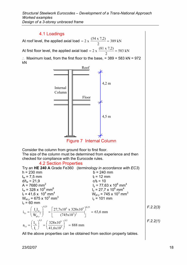
The internal column shown in Figure 7 is subject to loads from the roof and one floor. Design the column for the given loading, in grade Fe360 steel, as a member in simple framing.
Structural Steelwork Eurocodes – Development of a Trans-National Approach Worked examples Design of a 3-storey unbraced frame
23/02/07 18
4.1 Loadings At roof level, the applied axial load = =2 x (54 x 7,2)
2389 kN
At first floor level, the applied axial load = =2 x (81 x 7,2)2
583 kN
∴ Maximum load, from the first floor to the base, = 389 + 583 kN = 972 kN
4,2 m
4,5 m
Floor
Roof
InternalColumn
Figure 7 Internal Column
Consider the column from ground floor to first floor. The size of the column must be determined from experience and then checked for compliance with the Eurocode rules.
4.2 Section Properties Try an HE 240 A Grade Fe360 (terminology in accordance with EC3) h = 230 mm b = 240 mm tw = 7,5 mm tf = 12 mm d/tw = 21,9 c/tf = 10 A = 7680 mm2 Iy = 77,63 x 106 mm4 Iw = 328 x 109 mm6 Iz = 27,7 x 106 mm4 It = 41,6 x 104 mm4 Wpl.y = 745 x 103 mm3 Wel.y = 675 x 103 mm3 iy = 101 mm iz = 60 mm
i I IW
27,7x10 x 328x10(745x10 )
63,6 mmLtz w
pl.y2
0,256 9
3 2
0,25
=
=
=
F.2.2(3)
a II
328x1041,6x10
888 mmLtw
t
0,5 9
4
0,5
=
=
=
F.2.2(1)
All the above properties can be obtained from section property tables.
Structural Steelwork Eurocodes – Development of a Trans-National Approach Worked examples Design of a 3-storey unbraced frame
23/02/07 19
4.3 Classification of Cross Section This section is designed to withstand axial force only. No moment is applied as the connecting beams are equally loaded.
5.3
4.3.1 Flange (subject to compression) Class 1 limiting value of c/tf for an outstand of a rolled section is 10ε. ε = 235 / fy where fy = 235 N/mm2, therefore ε = 1. From section properties, c/tf = 10
Table 5.3.1 (Sheet 3)
4.3.2 Web (subject to compression) Class 1 limiting value of d/tw for a web subject to compression only is 33ε. From section properties, d/tw = 21,9 c/tf ≤ 10ε and d/tw ≤ 33ε ∴Class 1 section.
Table 5.3.1 (Sheet 1) Table 3.5.1 (Sheets 1 and 3) Class 1 section
4.4 Resistance of Cross-Section 5.4.4 It is highly unlikely that the resistance of the cross-section will be the critical case - it is generally the buckling resistance that governs the suitability of a cross-section. For the sake of completeness, the check is included in this worked example. The resistance of the cross-section will only be critical if a short, stocky column is used.
For members in axial compression, the design value of the compressive force, NSd, at each cross-section shall satisfy NSd ≤ Nc.Rd
5.4.4(1)
For a class 1 cross-section, the design compression resistance of the cross-section, Nc.Rd, may be determined as:
NAf
c.Rdy
M0
=γ
where A is cross-sectional area = 7680 mm2, fy is the yield strength = 235 N/mm2, and γM0 is the partial material safety factor = 1,1.
N 7680 x 2351,1x10
1641 kNc.Rd 3= =
NSd = 972 kN, therefore Nsd ≤ Nc.Rd. The section can resist the applied axial load.
5.4.4(2) Table 3.1 5.1.1(2)
Structural Steelwork Eurocodes – Development of a Trans-National Approach Worked examples Design of a 3-storey unbraced frame
23/02/07 20
4.5 Buckling Resistance of Member A class 1 member should be checked for failure due to flexural and lateral torsional buckling. Here, since My = Mz = 0, only failure due to flexural buckling needs to be checked.
The design buckling resistance of a compression member shall be taken as:
NAf
b.RdA y
M1
=χβ
γ
where χ is the reduction factor for the relevant buckling mode, βA = 1 for class 1 cross-section, A is the cross-sectional area = 7680 mm2, fy is the yield strength of the steel = 235 N/mm2 , and γM1 is the partial material safety factor for buckling resistance = 1,1. The magnitude of the reduction factor, χ depends on the reduced slenderness of the columns. χ is the lesser of χy and χz, where χy and χz are the reduction factors from clause 5.5.1 for the y-y and z-z axes respectively. Values of χ for the appropriate value of non-dimensional slenderness, λ may be obtained from Table 5.5.2.
5.5.1.1(1) 5.5.1.1(1) Table 3.1 5.1.1.(2)
Non-dimensional slenderness, λλλ
β=
1A
0,5
Where the slenderness, λ =li
l is the column buckling length, and i is the radius of gyration about the relevant axis. The braced frame is designed as a simple “pinned” structure. Therefore, the buckling length ratio l/L is equal to 1 - the buckling length is equal to the system length.
λ π ε1y
0,5Ef
93,9=
=
5.5.1.2(1) 5.5.1.4(3) 5.5.1.5(2) 5.5.1.2(1)
4.6 Determination of Reduction Factor, χy Slenderness, λy = l/iy = 4500/101 = 44,6 λ1 = 93,9ε = 93,9 x 1 = 93,9
Non-dimensional slenderness, λλλ
βyy
1A
0,5 0,544,693,9
x 1 0,47=
=
=
5.5.1.4(3)
From Table 5.5.2, using buckling curve b, the reduction factor, χy = 0,89 Table 5.5.3 Table 5.5.2

Structural Steelwork Eurocodes – Development of a Trans-National Approach Worked examples Design of a 3-storey unbraced frame
23/02/07 21
4.7 Determination of Reduction Factor, χz Slenderness, λz = l/iz = 4500/60 = 75 λ1 = 93,9ε = 93,9 x 1 = 93,9
Non-dimensional slenderness, λλλ
βyz
1A
0,5 0,57593,9
x 1 0,8=
=
=
From Table 5.5.2, using buckling curve c,the reduction factor, χz = 0,6622
5.5.1.4(3) Table 5.5.3 Table 5.5.2
Therefore χ = χz = 0,6622. Design buckling resistance of member:
NAf 0,6622 x 1 x 7680 x 235
1,1x101086 kNb.Rd
A y
M13= = =
χβγ
The design buckling resistance of the member is greater than the applied load (972 kN), therefore the column is satisfactory. The column is OK.
5.5.1.1(1)
5. External Column
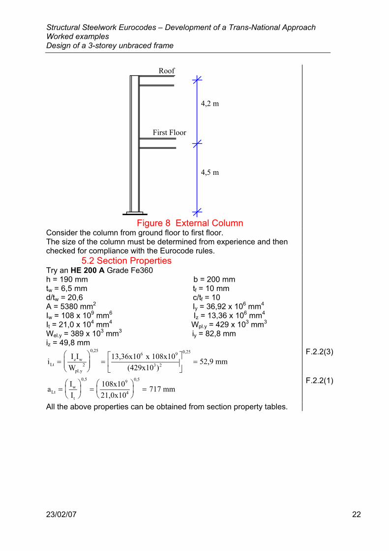
The external column shown in Figure 8 is subject to loads from the roof and one floor. Design the column for the loading given below, in grade Fe360 steel, as a member in simple framing.
5.1 Loadings At roof level, the applied axial load = =
(54 x 7,2)2
194 kN
At first floor level, the applied axial load = =(81 x 7,2)
2292 kN
∴ Maximum load, from first floor to base, = 194 + 292 kN = 486 kN
The beams in the frame are designed to span from column centre to column centre, therefore all axial load is applied at the mid-point of the column. No moment due to eccentricity of applied load is therefore applied to the column. See Annex H
Structural Steelwork Eurocodes – Development of a Trans-National Approach Worked examples Design of a 3-storey unbraced frame
23/02/07 22
4,2 m
4,5 m
First Floor
Roof
Figure 8 External Column
Consider the column from ground floor to first floor. The size of the column must be determined from experience and then checked for compliance with the Eurocode rules.
5.2 Section Properties Try an HE 200 A Grade Fe360 h = 190 mm b = 200 mm tw = 6,5 mm tf = 10 mm d/tw = 20,6 c/tf = 10 A = 5380 mm2 Iy = 36,92 x 106 mm4 Iw = 108 x 109 mm6 Iz = 13,36 x 106 mm4 It = 21,0 x 104 mm4 Wpl.y = 429 x 103 mm3 Wel.y = 389 x 103 mm3 iy = 82,8 mm iz = 49,8 mm
i I IW
13,36x10 x 108x10(429x10 )
52,9 mmLtz w
pl.y2
0,256 9
3 2
0,25
=
=
=
F.2.2(3)
a II
108x1021,0x10
717 mmLtw
t
0,5 9
4
0,5
=
=
=
F.2.2(1)
All the above properties can be obtained from section property tables.
Structural Steelwork Eurocodes – Development of a Trans-National Approach Worked examples Design of a 3-storey unbraced frame
23/02/07 23
5.3 Classification of Cross Section This section is designed to withstand axial force only.
5.3
5.3.1 Flange (subject to compression) Class 1 limiting value of c/tf for an outstand of a rolled section is 10ε. ε = 235 / fy where fy = 235 N/mm2, ∴ ε = 1.
10ε = 10 x 1 = 10 From section properties, c/tf = 10
Table 5.3.1 (Sheet 3)
5.3.2 Web (subject to compression) Class 1 limiting value of d/tw for a web subject to compression only is 33ε. ε = 235 / fy where fy = 235 N/mm2, ∴ ε = 1.
33ε = 33 x 1 = 33 From section properties, d/tw = 20,6
Table 5.3.1 (Sheet 1)
c/tf ≤ 10ε and d/tw ≤ 33ε ∴Class 1 section.
Table 5.3.1 (Sheets 1 and 3)
5.4 Resistance of Cross-Section 5.4.4 It is highly unlikely that the resistance of the cross-section will be the critical case - it is generally the buckling resistance that governs the suitability of a cross-section. For the sake of completeness, the check is included in this worked example. The resistance of the cross-section will only be critical if a short stocky column is used.
For members in axial compression, the design value of the compressive force, NSd, at each cross-section shall satisfy NSd ≤ Nc.Rd
5.4.4(1)
For a class 1 cross-section, the design compression resistance of the cross-section, Nc.Rd, may be determined as:
NAf
c.Rdy
M0
=γ
where A is cross-sectional area = 5380 mm2, fy is the yield strength = 235 N/mm2, and γM0 is the partial material safety factor = 1,1.
N 5380 x 2351,1x10
1149 kNc.Rd 3= =
NSd = 486 kN, therefore Nsd ≤ Nc.Rd. The section can resist the applied axial load.
5.4.4(2) Table 3.1 5.1.1(2)
Structural Steelwork Eurocodes – Development of a Trans-National Approach Worked examples Design of a 3-storey unbraced frame
23/02/07 24
5.5 Buckling Resistance of Member A class 1 member should be checked for failure due to flexural and lateral torsional buckling. Here, since My = Mz = 0, only failure due to flexural buckling needs to be checked.
The design buckling resistance of a compression member shall be taken as:
NAf
b.RdA y
M1
=χβ
γ
where χ is the reduction factor for the relevant buckling mode, βA = 1 for class 1 cross-section, A is the cross-sectional area = 5380 mm2, fy is the yield strength of the steel = 235 N/mm2 , and γM1 is the partial material safety factor for buckling resistance = 1,1. The magnitude of the reduction factor, χ depends on the reduced slenderness of the columns. χ is the lesser of χy and χz, where χy and χz are the reduction factors from clause 5.5.1 for the y-y and z-z axes respectively. Values of χ for the appropriate value of non-dimensional slenderness, λ may be obtained from Table 5.5.2.
5.5.1.1(1) 5.5.1.1(1) Table 3.1 5.1.1.(2)
Non-dimensional slenderness, λλλ
β=
1A
0,5
Where the slenderness, λ =li
l is the column buckling length, and i is the radius of gyration about the relevant axis. The braced frame is designed as a simple “pinned” structure. Therefore, the buckling length ratio l/L is equal to 1 - the buckling length is equal to the system length.
λ π ε1y
0,5Ef
93,9=
=
5.5.1.2(1) 5.5.1.4(3) 5.5.1.5(2) Annex E Figure E.2.1 5.5.1.2(1)
5.6 Determination of Reduction Factor, χy Slenderness, λy = l/iy = 4500/82,8 = 54,3 λ1 = 93,9ε = 93,9 x 1 = 93,9
Non-dimensional slenderness, λλλ
βyy
1A
0,5 0,554,393,9
x 1 0,58=
=
=
5.5.1.4(3)
From Table 5.5.2, using buckling curve b, the reduction factor, χy = 0,84 Table 5.5.3 Table 5.5.2
Structural Steelwork Eurocodes – Development of a Trans-National Approach Worked examples Design of a 3-storey unbraced frame
23/02/07 25
5.7 Determination of Reduction Factor, χz Slenderness, λz = l/iz = 4500/49,8 = 90,4 λ1 = 93,9ε = 93,9 x 1 = 93,9
Non-dimensional slenderness, λλλ
βyz
1A
0,5 0,590,493,9
x 1 0,96=
=
=
From Table 5.5.2, using buckling curve c,the reduction factor, χz = 0,55
5.5.1.4(3) Table 5.5.3 Table 5.5.2
Therefore χ = χz = 0,55. Design buckling resistance of member:
NAf 0,55 x 1 x 5380 x 235
1,1x10632,2 kNb.Rd
A y
M13= = =
χβγ
The design buckling resistance of the member is greater than the applied load (486 kN), therefore the column is satisfactory. The column is OK.
5.5.1.1(1)
6. Design of Cross-Bracing
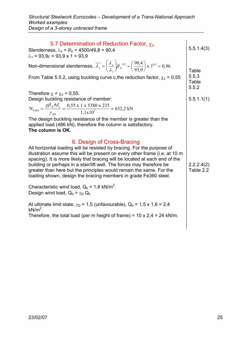
All horizontal loading will be resisted by bracing. For the purpose of illustration assume this will be present on every other frame (i.e. at 10 m spacing). It is more likely that bracing will be located at each end of the building or perhaps in a stair/lift well. The forces may therefore be greater than here but the principles would remain the same. For the loading shown, design the bracing members in grade Fe360 steel. Characteristic wind load, Qk = 1,6 kN/m2. Design wind load, Qd = γQ Qk At ultimate limit state, γQ = 1,5 (unfavourable), Qd = 1,5 x 1,6 = 2,4 kN/m2. Therefore, the total load (per m height of frame) = 10 x 2,4 = 24 kN/m.
2.2.2.4(2) Table 2.2
Structural Steelwork Eurocodes – Development of a Trans-National Approach Worked examples Design of a 3-storey unbraced frame
23/02/07 26
7,2 m
4,2 m
4,5 m
24kN/m
Figure 9 Wind Load on Frame
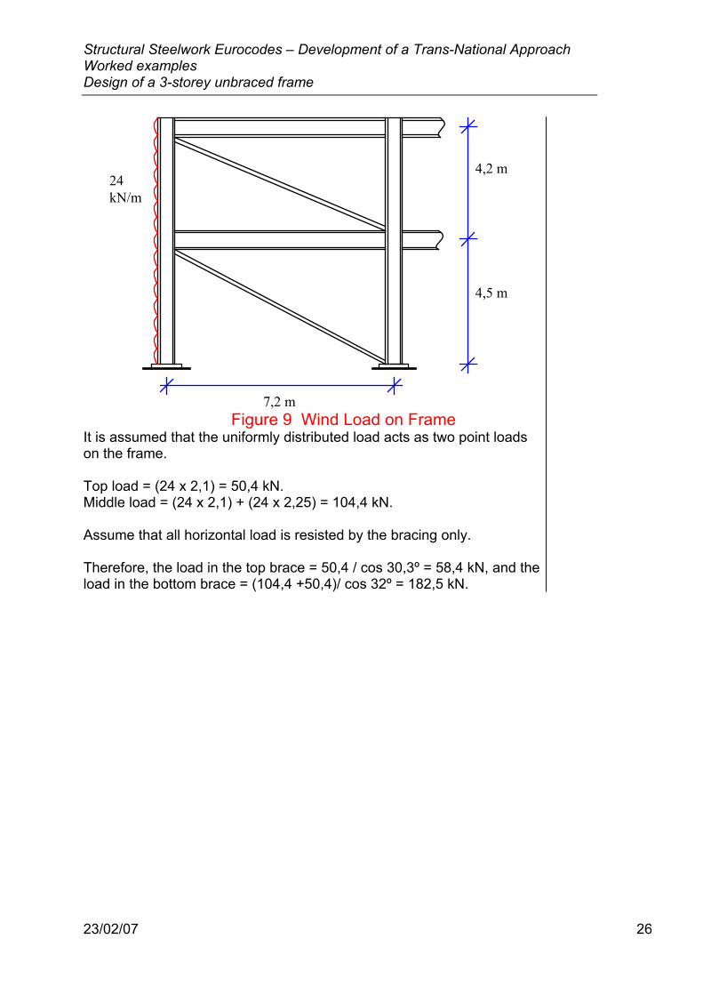
It is assumed that the uniformly distributed load acts as two point loads on the frame. Top load = (24 x 2,1) = 50,4 kN. Middle load = (24 x 2,1) + (24 x 2,25) = 104,4 kN. Assume that all horizontal load is resisted by the bracing only. Therefore, the load in the top brace = 50,4 / cos 30,3º = 58,4 kN, and the load in the bottom brace = (104,4 +50,4)/ cos 32º = 182,5 kN.
Structural Steelwork Eurocodes – Development of a Trans-National Approach Worked examples Design of a 3-storey unbraced frame
23/02/07 27
104,4kN
7,2 m
4,2 m
4,5 m
50,4kN
58,4 kN
182,5 kN
Figure 10 Equivalent Point Wind Loads and Loads
Within Bracing
Design the bottom brace, as this carries the greater load. Try a CHS 175 x 5,0
6.1 Section Properties Depth of section, d = 175 mm, Thickness, t = 5 mm Area of section, A = 2670 mm2, Ratio for local buckling, d/t = 35, Radius of gyration, i = 60,1 mm.
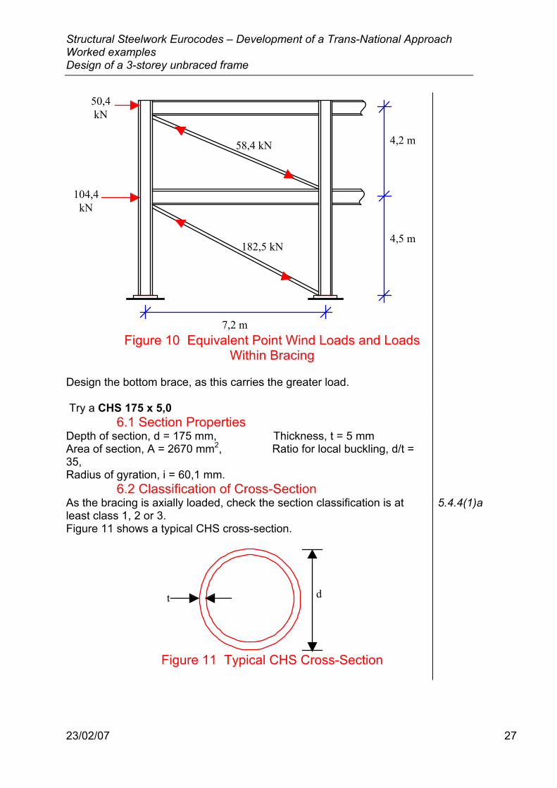
6.2 Classification of Cross-Section As the bracing is axially loaded, check the section classification is at least class 1, 2 or 3. Figure 11 shows a typical CHS cross-section.
5.4.4(1)a
t d
Figure 11 Typical CHS Cross-Section
Structural Steelwork Eurocodes – Development of a Trans-National Approach Worked examples Design of a 3-storey unbraced frame
23/02/07 28
Class 1 limiting value of d/t for a tubular section is 50ε2. ε = 235 / fy where fy = 235 N/mm2, ∴ ε = 1.
50ε2 = 50 x 1 = 50 From section properties, d/t =35, therefore the section is Class 1.
Table 5.3.1 (Sheet 4)
6.3 Design of Compression Member The bracing members need to be checked as axially loaded.
6.3.1 Resistance of Cross-Section It is highly unlikely that the resistance of the cross-section will be the critical case - it is generally the buckling resistance that governs the suitability of a cross-section. For the sake of completeness, the check is included in this worked example. The resistance of the cross-section will only be critical if a short, stocky column is used.
The applied axial load, NSd, must be less than the design compressive resistance of the cross-section, Nc.Rd. Applied axial load, NSd = 182,5 kN.
Design compressive resistance of cross-section, Nc.Rd = NAf
pl.Rdy
M0
=γ
Where A is the cross-sectional area = 2670 mm2, fy is the yield strength of the steel = 235 N/ mm2, and γM0 is the partial material safety factor = 1,1.
N 2670 x 235 x 10
kNpl.Rd 3= =11
570 4,
,
The design compressive resistance of the cross-section, Nc.Rd = 570,4 kN, is greater than the applied axial load, NSd = 182,5 kN. Therefore the section is satisfactory.
5.4.4(1) Table 3.1 5.1.1(2)
6.3.2 Design Buckling Resistance A class 1 member subject to axial compression should be checked for failure due to buckling.
The design buckling resistance of a compression member shall be taken as:
NAf
b.RdA y
M1
=χβ
γ
where χ is the reduction factor for the relevant buckling mode, βA = 1 for class 1 cross-section, A is the cross-sectional area = 2670 mm2, fy is the yield strength of the steel = 235 N/mm2 , and γM1 is the partial material safety factor for buckling resistance = 1,1. Values of χ for the appropriate value of non-dimensional slenderness, λ may be obtained from Table 5.5.2.
5.5.1.1(1) 5.5.1.1(1) Table 3.1 5.1.1.(2)

Structural Steelwork Eurocodes – Development of a Trans-National Approach Worked examples Design of a 3-storey unbraced frame
23/02/07 29
Non-dimensional slenderness, λλλ
β=
1A
0,5
Where the slenderness, λ =li
l is the member buckling length, and i is the radius of gyration. The bracing is designed as a simple “pinned” member. Therefore, the buckling length ratio l/L is equal to 1 - the buckling length is equal to the system length. Length of member = ( )4 5 7 2 85002 2, ,+ = mm
λ π ε1y
0,5Ef
93,9=
=
5.5.1.2(1) 5.5.1.4(3) 5.5.1.5(2) Annex E Figure E.2.1 5.5.1.2(1)
6.3.3 Determination Of Reduction Factor, χ Slenderness, λ = l/i = 8500/60,1 = 141 λ1 = 93,9ε = 93,9 x 1 = 93,9
Non-dimensional slenderness, λλλ
β=
=
=1
A0,5 0,5141
93,9 x 1 1,50
5.5.1.4(3)
From Table 5.5.2, using buckling curve b, the reduction factor, χ = 0,3422.
Table 5.5.3 Table 5.5.2
Design buckling resistance of member:
NAf 0,3422 x 1 x 2670 x 235
1,1x10195,2 kNb.Rd
A y
M13= = =
χβγ
The design buckling resistance of the member is greater than the applied load (182,5 kN), therefore the bracing is satisfactory.
5.5.1.1(1)

Structural Steelwork Eurocodes – Development of a Trans-National Approach Worked examples Design of a 3-storey unbraced frame
23/02/07 30
6.4 Design of Tension Member When the wind load is applied in the opposite direction, the bracing will be loaded in tension. The section therefore needs to be checked, for the same magnitude of loading, to ensure it is also satisfactory in tension.
104,4kN
7,2 m
4,2 m
4,5 m
50,4kN
58,4 kN
182,5 kN
Figure 12 Equivalent Point Wind Loads and Loads Within Bracing
6.4.1 Resistance of Cross-Section The applied axial load, NSd, must be less than the design tension resistance of the cross-section, Nt.Rd. Applied axial load, NSd = 182,5 kN.
Design tension resistance of the cross-section, Nt.Rd = NAf
pl.Rdy
M0
=γ
where A is the cross-sectional area = 2670 mm2, fy is the yield strength of the steel = 235 N/ mm2, and γM0 is the partial material safety factor = 1,1.
N 2670 x 235 x 10
kNpl.Rd 3= =11
570 4,
,
The design tension resistance of the cross-section, Nt.Rd = 570,4 kN, is greater than the applied axial load, NSd = 182,5 kN. Therefore the section is satisfactory.
5.4.3(1) Table 3.1 5.1.1(2)
The bracing fulfils all the Eurocode requirements for members in tension and in compression, and is therefore satisfactory.
The frame is satisfactory for all EC3 checks
Structural Steelwork Eurocodes – Development of a Trans-National Approach Worked examples Design of a 3-storey unbraced frame
23/02/07 31
7. Concluding Summary
Structural Steelwork Eurocodes – Development of a Trans-National Approach Worked examples Design of a 3-storey unbraced frame
23/02/07 32
Structural Steelwork Eurocodes Development of
A Trans-national ApproachCourse: Eurocode 3 Module 7 : Worked Examples
Lecture 22 : Design of an unbraced sway frame with rigid joints Summary:
NOTE – This example is a draft version • • • •
Pre-requisites: •
Notes for Tutors: This material comprises one 60 minute lecture.
Objectives: • To explain the main principles of EC3 by practical worked example.
References: • Eurocode 3: Design of steel structures Part 1.1 General rules and rules for
buildings • •
Contents:
Structural Steelwork Eurocodes – Development of a Trans-National Approach Worked examples Design of a 3-storey unbraced frame
23/02/07 33
WORKED EXAMPLE 3 Design of a Sway Frame
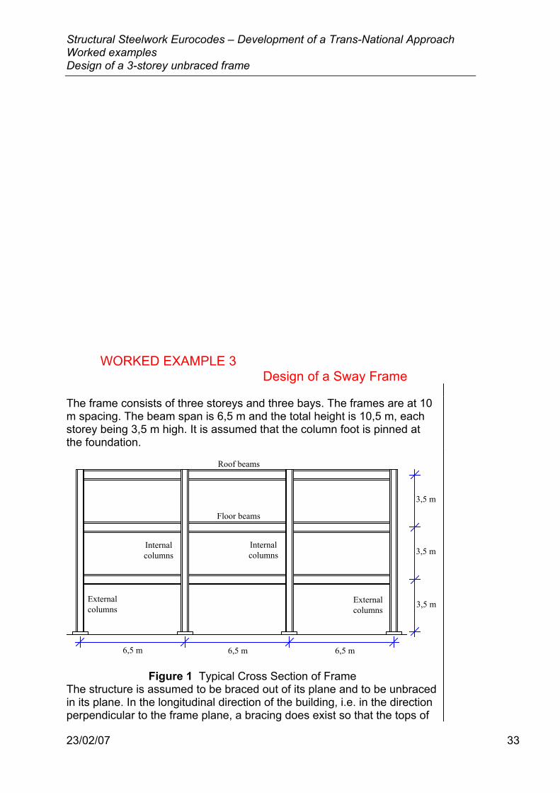
The frame consists of three storeys and three bays. The frames are at 10 m spacing. The beam span is 6,5 m and the total height is 10,5 m, each storey being 3,5 m high. It is assumed that the column foot is pinned at the foundation.
Internalcolumns
Internalcolumns
Externalcolumns
Externalcolumns
Roof beams
Floor beams
6,5 m 6,5 m 6,5 m
3,5 m
3,5 m
3,5 m
Figure 1 Typical Cross Section of Frame
The structure is assumed to be braced out of its plane and to be unbraced in its plane. In the longitudinal direction of the building, i.e. in the direction perpendicular to the frame plane, a bracing does exist so that the tops of
Structural Steelwork Eurocodes – Development of a Trans-National Approach Worked examples Design of a 3-storey unbraced frame
23/02/07 34
the columns are held in place. The lateral support for the floor beams is provided by the floor slabs. All the beam-to-column joints are assumed to be perfectly rigid. The connections must be capable of transmitting the forces and moments calculated in design. With these assumptions, the frame is classified as ‘continuous’, and the internal forces and moments are determined using a global elastic analysis which assumes the members to be effectively held in position.
6.4.2.2(3) 5.2.2.3
The steel grade selected for beams, columns and joints is Fe360 (fy = 235 N/mm2).
Table 3.1
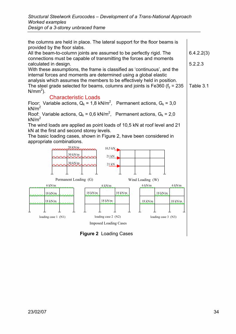
Characteristic Loads Floor: Variable actions, Qk = 1,8 kN/m2, Permanent actions, Gk = 3,0 kN/m2
Roof: Variable actions, Qk = 0,6 kN/m2, Permanent actions, Gk = 2,0 kN/m2
The wind loads are applied as point loads of 10,5 kN at roof level and 21 kN at the first and second storey levels.
The basic loading cases, shown in Figure 2, have been considered in appropriate combinations.
Permanent Loading (G) Wind Loading (W)
loading case 1 (N1) loading case 2 (N2) loading case 3 (N3)
Imposed Loading Cases
20 kN/m
30 kN/m
30 kN/m
10,5 kN
21 kN
21 kN
6 kN/m 6 kN/m 6 kN/m 6 kN/m
18 kN/m
18 kN/m
18 kN/m 18 kN/m
18 kN/m
18 kN/m
18 kN/m 18 kN/m
Figure 2 Loading Cases
Structural Steelwork Eurocodes – Development of a Trans-National Approach Worked examples Design of a 3-storey unbraced frame
23/02/07 35
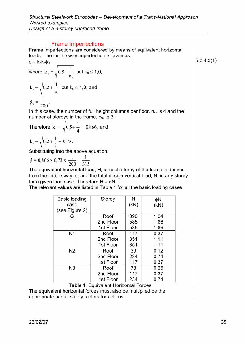
Frame Imperfections Frame imperfections are considered by means of equivalent horizontal loads. The initial sway imperfection is given as: φ = kcksφ0
where k = 0,5 + 1nc
c
but kc ≤ 1,0,
kns
s
= +0 2 1, but ks ≤ 1,0, and
φ 01
200= .
In this case, the number of full height columns per floor, nc, is 4 and the number of storeys in the frame, ns, is 3.
Therefore kc = + =0 5 14
0 866, , , and
ks = + =0 2 13
0 73, , .
Substituting into the above equation:
φ = 0,866 x 0,73 x 1200
=1
315
5.2.4.3(1)
The equivalent horizontal load, H, at each storey of the frame is derived from the initial sway, φ, and the total design vertical load, N, in any storey for a given load case. Therefore H = φN. The relevant values are listed in Table 1 for all the basic loading cases.
Basic loading
case (see Figure 2)
Storey N (kN)
φN (kN)
G Roof 390 1,24 2nd Floor 585 1,86 1st Floor 585 1,86 N1 Roof 117 0,37 2nd Floor 351 1,11 1st Floor 351 1,11 N2 Roof 39 0,12 2nd Floor 234 0,74 1st Floor 117 0,37 N3 Roof 78 0,25 2nd Floor 117 0,37 1st Floor 234 0,74
Table 1 Equivalent Horizontal Forces The equivalent horizontal forces must also be multiplied be the appropriate partial safety factors for actions.
Structural Steelwork Eurocodes – Development of a Trans-National Approach Worked examples Design of a 3-storey unbraced frame
23/02/07 36
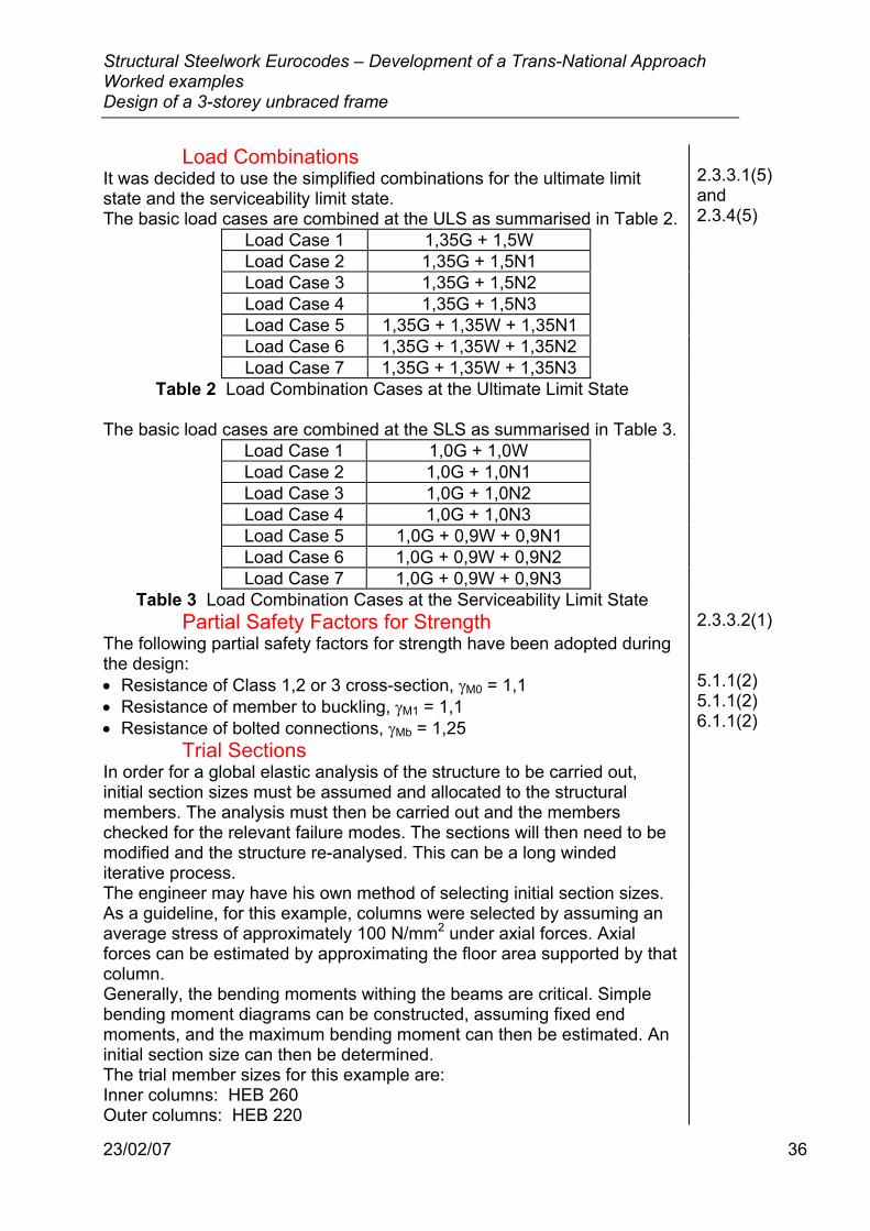
Load Combinations It was decided to use the simplified combinations for the ultimate limit state and the serviceability limit state. The basic load cases are combined at the ULS as summarised in Table 2.
2.3.3.1(5) and 2.3.4(5)
Load Case 1 1,35G + 1,5W Load Case 2 1,35G + 1,5N1 Load Case 3 1,35G + 1,5N2 Load Case 4 1,35G + 1,5N3 Load Case 5 1,35G + 1,35W + 1,35N1 Load Case 6 1,35G + 1,35W + 1,35N2 Load Case 7 1,35G + 1,35W + 1,35N3
Table 2 Load Combination Cases at the Ultimate Limit State The basic load cases are combined at the SLS as summarised in Table 3.
Load Case 1 1,0G + 1,0W Load Case 2 1,0G + 1,0N1 Load Case 3 1,0G + 1,0N2 Load Case 4 1,0G + 1,0N3 Load Case 5 1,0G + 0,9W + 0,9N1 Load Case 6 1,0G + 0,9W + 0,9N2 Load Case 7 1,0G + 0,9W + 0,9N3
Table 3 Load Combination Cases at the Serviceability Limit State Partial Safety Factors for Strength
The following partial safety factors for strength have been adopted during the design: • Resistance of Class 1,2 or 3 cross-section, γM0 = 1,1 • Resistance of member to buckling, γM1 = 1,1 • Resistance of bolted connections, γMb = 1,25
2.3.3.2(1) 5.1.1(2) 5.1.1(2) 6.1.1(2)
Trial Sections In order for a global elastic analysis of the structure to be carried out, initial section sizes must be assumed and allocated to the structural members. The analysis must then be carried out and the members checked for the relevant failure modes. The sections will then need to be modified and the structure re-analysed. This can be a long winded iterative process.
The engineer may have his own method of selecting initial section sizes. As a guideline, for this example, columns were selected by assuming an average stress of approximately 100 N/mm2 under axial forces. Axial forces can be estimated by approximating the floor area supported by that column. Generally, the bending moments withing the beams are critical. Simple bending moment diagrams can be constructed, assuming fixed end moments, and the maximum bending moment can then be estimated. An initial section size can then be determined.
The trial member sizes for this example are: Inner columns: HEB 260 Outer columns: HEB 220
Structural Steelwork Eurocodes – Development of a Trans-National Approach Worked examples Design of a 3-storey unbraced frame
23/02/07 37
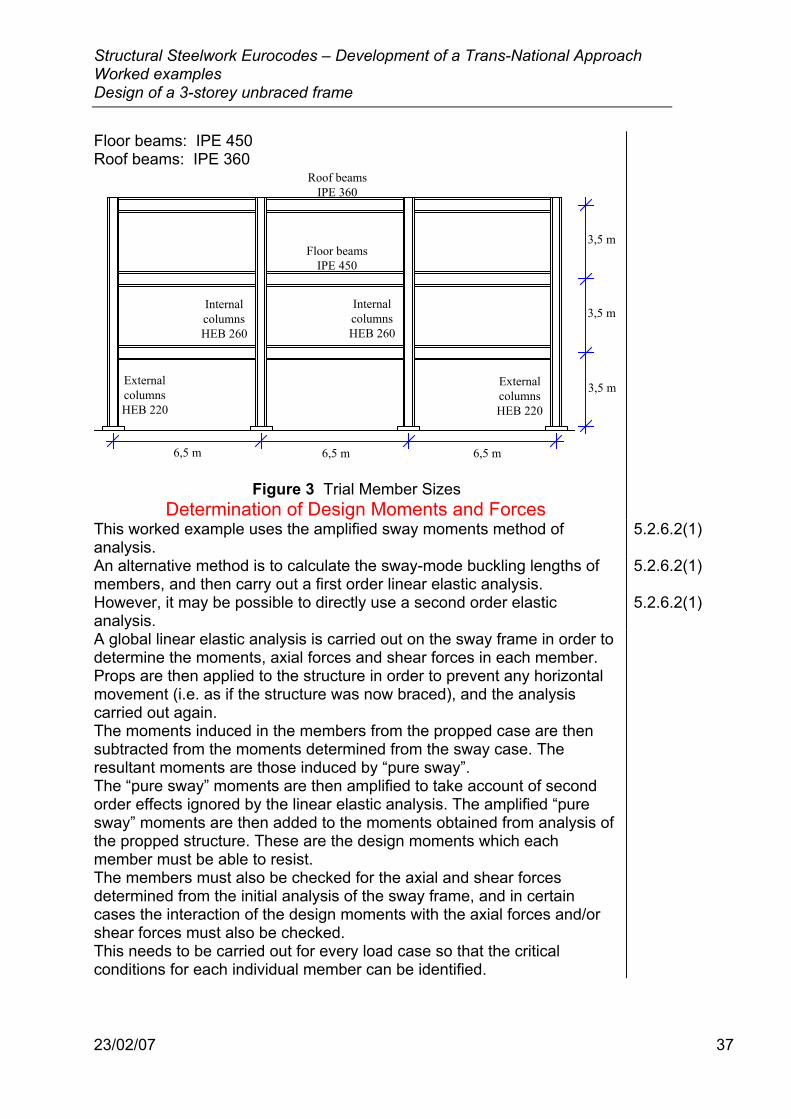
Floor beams: IPE 450 Roof beams: IPE 360
InternalcolumnsHEB 260
InternalcolumnsHEB 260
ExternalcolumnsHEB 220
ExternalcolumnsHEB 220
Roof beamsIPE 360
Floor beamsIPE 450
6,5 m 6,5 m 6,5 m
3,5 m
3,5 m
3,5 m
Figure 3 Trial Member Sizes
Determination of Design Moments and Forces This worked example uses the amplified sway moments method of analysis.
5.2.6.2(1)
An alternative method is to calculate the sway-mode buckling lengths of members, and then carry out a first order linear elastic analysis.
5.2.6.2(1)
However, it may be possible to directly use a second order elastic analysis.
5.2.6.2(1)
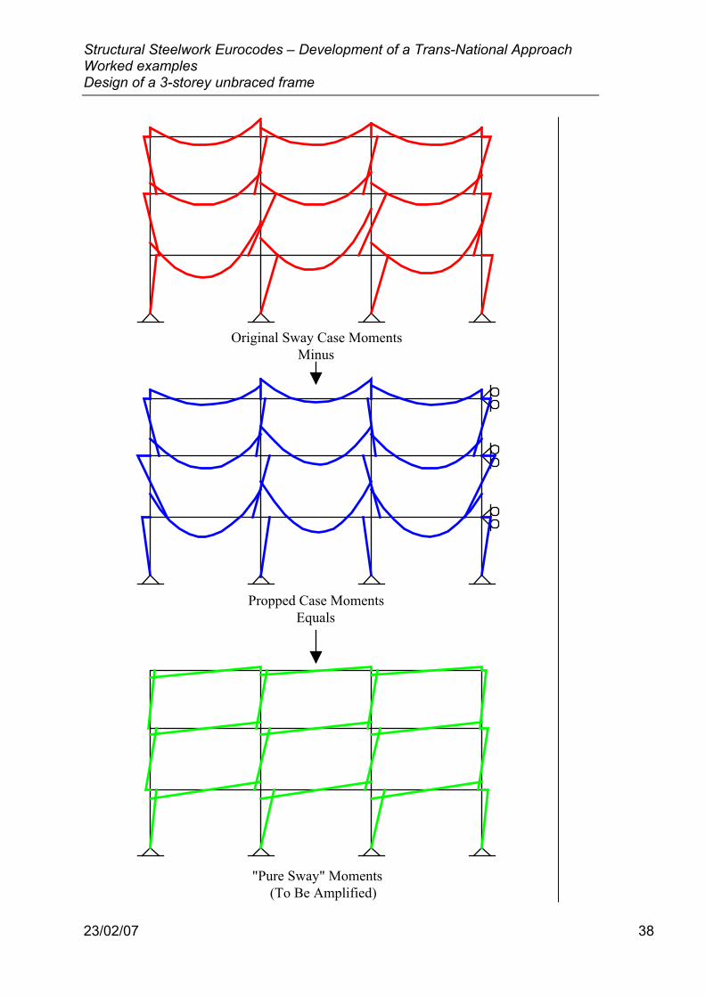
A global linear elastic analysis is carried out on the sway frame in order to determine the moments, axial forces and shear forces in each member. Props are then applied to the structure in order to prevent any horizontal movement (i.e. as if the structure was now braced), and the analysis carried out again. The moments induced in the members from the propped case are then subtracted from the moments determined from the sway case. The resultant moments are those induced by “pure sway”. The “pure sway” moments are then amplified to take account of second order effects ignored by the linear elastic analysis. The amplified “pure sway” moments are then added to the moments obtained from analysis of the propped structure. These are the design moments which each member must be able to resist. The members must also be checked for the axial and shear forces determined from the initial analysis of the sway frame, and in certain cases the interaction of the design moments with the axial forces and/or shear forces must also be checked. This needs to be carried out for every load case so that the critical conditions for each individual member can be identified.
Structural Steelwork Eurocodes – Development of a Trans-National Approach Worked examples Design of a 3-storey unbraced frame
23/02/07 38
Original Sway Case MomentsMinus
Propped Case MomentsEquals
"Pure Sway" Moments(To Be Amplified)
Structural Steelwork Eurocodes – Development of a Trans-National Approach Worked examples Design of a 3-storey unbraced frame
23/02/07 39
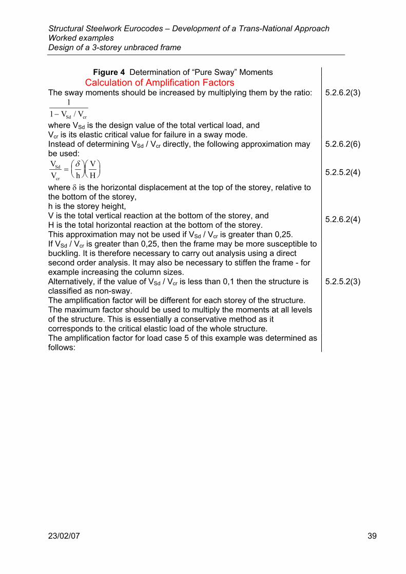
Figure 4 Determination of “Pure Sway” Moments Calculation of Amplification Factors
The sway moments should be increased by multiplying them by the ratio: 1
1− V VSd cr/
where VSd is the design value of the total vertical load, and Vcr is its elastic critical value for failure in a sway mode.
5.2.6.2(3)
Instead of determining VSd / Vcr directly, the following approximation may be used: VV h
VH
Sd
cr
=
δ
where δ is the horizontal displacement at the top of the storey, relative to the bottom of the storey, h is the storey height, V is the total vertical reaction at the bottom of the storey, and H is the total horizontal reaction at the bottom of the storey. This approximation may not be used if VSd / Vcr is greater than 0,25.
5.2.6.2(6) 5.2.5.2(4) 5.2.6.2(4)
If VSd / Vcr is greater than 0,25, then the frame may be more susceptible to buckling. It is therefore necessary to carry out analysis using a direct second order analysis. It may also be necessary to stiffen the frame - for example increasing the column sizes.
Alternatively, if the value of VSd / Vcr is less than 0,1 then the structure is classified as non-sway.
5.2.5.2(3)
The amplification factor will be different for each storey of the structure. The maximum factor should be used to multiply the moments at all levels of the structure. This is essentially a conservative method as it corresponds to the critical elastic load of the whole structure.
The amplification factor for load case 5 of this example was determined as follows:
Structural Steelwork Eurocodes – Development of a Trans-National Approach Worked examples Design of a 3-storey unbraced frame
23/02/07 40
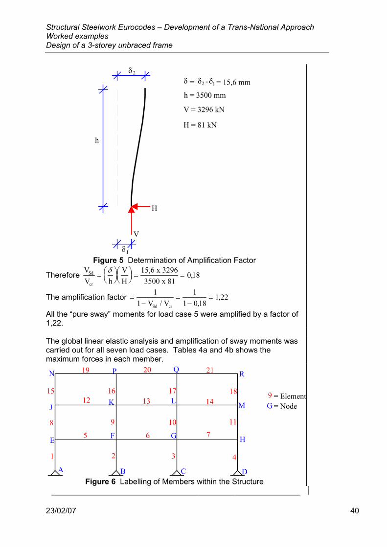
δ
h
V
H
δ
δδδ = - = 15,6 mm
h = 3500 mm
V = 3296 kN
H = 81 kN
2
2
1
1
Figure 5 Determination of Amplification Factor
Therefore VV h
VH
15,6 x 32963500 x 81
Sd
cr
=
= =δ 0 18,
The amplification factor =−
=−
=1
11
1 0 181 22
V VSd cr/ ,,
All the “pure sway” moments for load case 5 were amplified by a factor of 1,22.
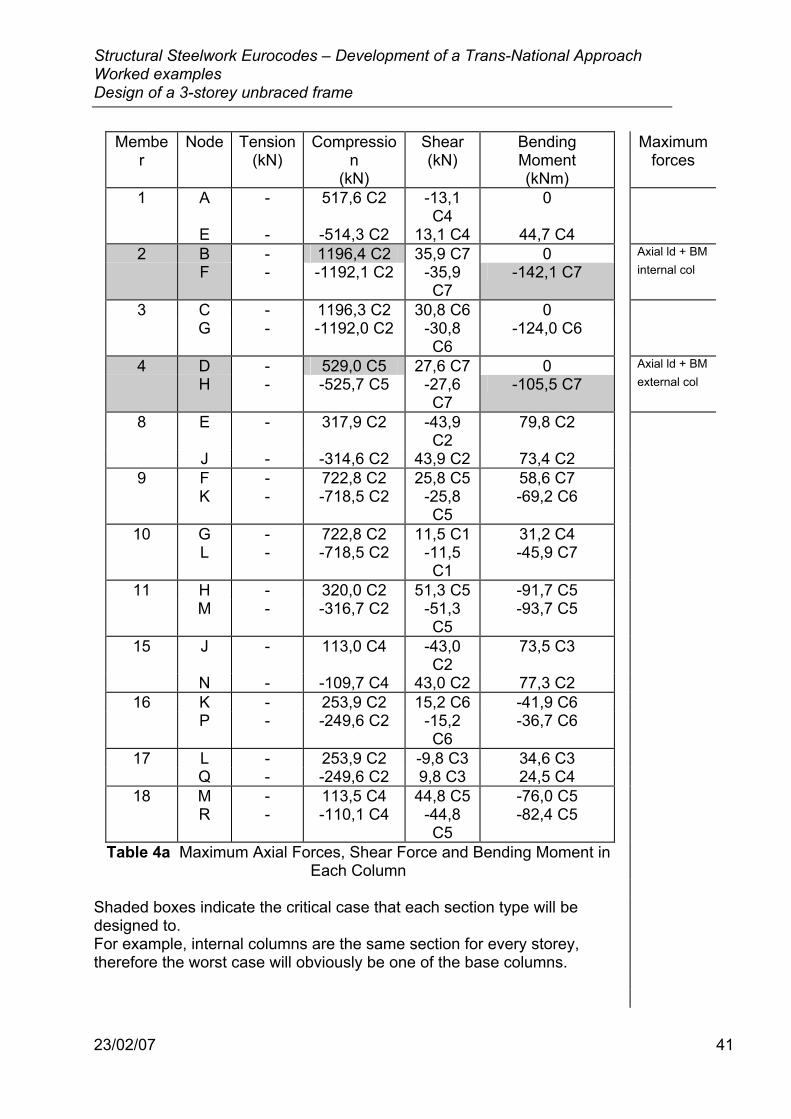
The global linear elastic analysis and amplification of sway moments was carried out for all seven load cases. Tables 4a and 4b shows the maximum forces in each member.
A B C D
E F G H
J K L M
N P Q R
1 2 3 4
5 6 78 9 10 11
12 13 1415 16 17 18
19 20 21
9G
= Element= Node
Figure 6 Labelling of Members within the Structure
Structural Steelwork Eurocodes – Development of a Trans-National Approach Worked examples Design of a 3-storey unbraced frame
23/02/07 41
Member
Node Tension (kN)
Compression
(kN)
Shear (kN)
Bending Moment (kNm)
Maximum forces
1 A - 517,6 C2 -13,1 C4
0
E - -514,3 C2 13,1 C4 44,7 C4 2 B - 1196,4 C2 35,9 C7 0 Axial ld + BM
F - -1192,1 C2 -35,9 C7
-142,1 C7 internal col
3 C - 1196,3 C2 30,8 C6 0 G - -1192,0 C2 -30,8
C6 -124,0 C6
4 D - 529,0 C5 27,6 C7 0 Axial ld + BM
H - -525,7 C5 -27,6 C7
-105,5 C7 external col
8 E - 317,9 C2 -43,9 C2
79,8 C2
J - -314,6 C2 43,9 C2 73,4 C2 9 F - 722,8 C2 25,8 C5 58,6 C7 K - -718,5 C2 -25,8
C5 -69,2 C6
10 G - 722,8 C2 11,5 C1 31,2 C4 L - -718,5 C2 -11,5
C1 -45,9 C7
11 H - 320,0 C2 51,3 C5 -91,7 C5 M - -316,7 C2 -51,3
C5 -93,7 C5
15 J - 113,0 C4 -43,0 C2
73,5 C3
N - -109,7 C4 43,0 C2 77,3 C2 16 K - 253,9 C2 15,2 C6 -41,9 C6 P - -249,6 C2 -15,2
C6 -36,7 C6
17 L - 253,9 C2 -9,8 C3 34,6 C3 Q - -249,6 C2 9,8 C3 24,5 C4 18 M - 113,5 C4 44,8 C5 -76,0 C5 R - -110,1 C4 -44,8
C5 -82,4 C5
Table 4a Maximum Axial Forces, Shear Force and Bending Moment in Each Column
Shaded boxes indicate the critical case that each section type will be designed to. For example, internal columns are the same section for every storey, therefore the worst case will obviously be one of the base columns.
Structural Steelwork Eurocodes – Development of a Trans-National Approach Worked examples Design of a 3-storey unbraced frame
23/02/07 42
Member
Node Tension (kN)
Compression
(kN)
Shear (kN)
Bending Moment (kNm)
Maximum forces
5 E -28,9 C2
8,5 C1 201,8 C4
-118,5 C4 Internal BM
F 28,9 C2 -8,5 C1 255,2 C5
341,6 C5 on floor beam
6 F -23,4 C2
1,4 C1 220,8 C3
-241,2 C2
G 23,4 C2 -1,4 C1 231,6 C5
310,7 C5
7 G -31,5 C2
- 244,2 C2
-271,7 C2 External BM
H 31,5 C2 - 213,3 C7
194,4 C5 on floor beam
12 J -0,6 G 28,1 C5 207,1 C3
-146,8 C2
K 0,6 G -28,1 C5 242,7 C2
288,6 C5
13 K -1,3 C4 15,6 C5 222,0 C4
-242,6 C2
L 1,3 C4 -15,6 C5 223,6 C2
261,3 C5
14 L -1,9 G 6,5 C5 241,0 C2
-271,5 C2
M 1,9 G -6,5 C5 208,5 C3
169,7 C5
19 N - 55,8 C5 109,7 C4
-77,3 C2 Internal BM
P - -55,8 C5 130,4 C2
150,2 C5 on roof beam
20 P - 42,4 C5 119,3 C3
-131,7 C2
Q - -42,4 C5 119,7 C2
135,8 C5
21 Q - 44,8 C5 129,9 C2
-146,7 C2 External BM
R - -44,8 C5 110,1 C4
82,4 C5 on roof beam
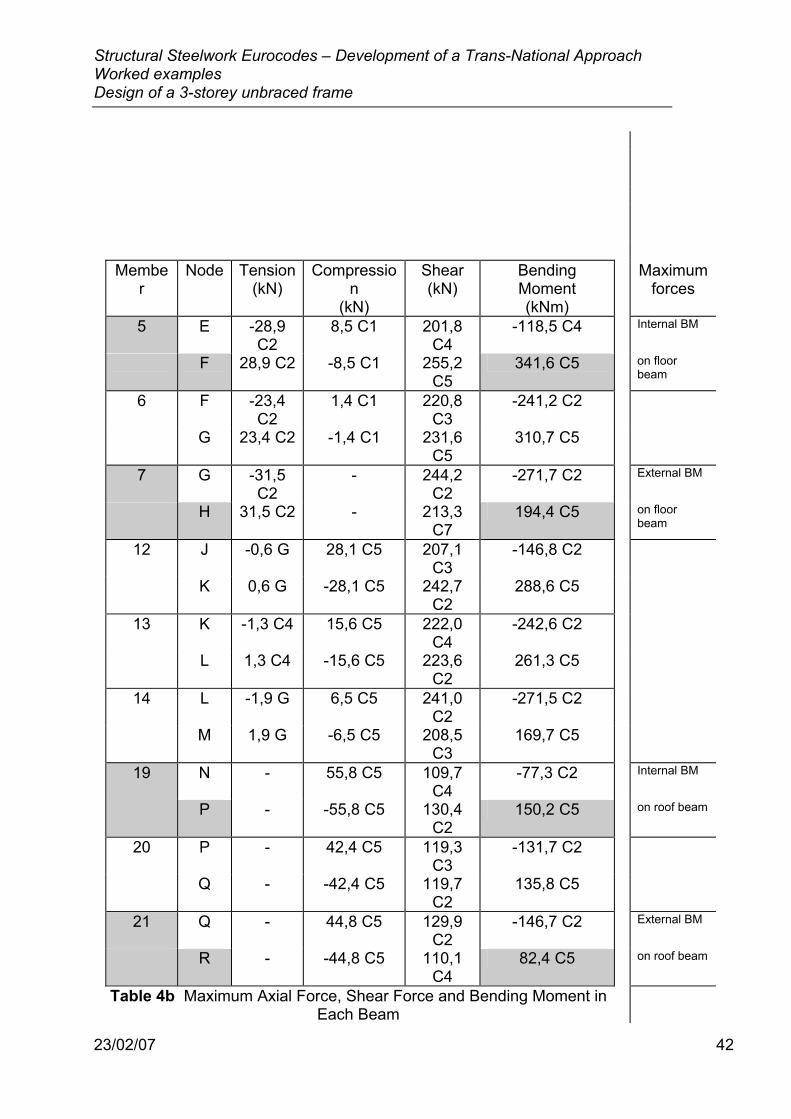
Table 4b Maximum Axial Force, Shear Force and Bending Moment in Each Beam
Structural Steelwork Eurocodes – Development of a Trans-National Approach Worked examples Design of a 3-storey unbraced frame
23/02/07 43
Shaded boxes indicate the critical case that each section type will be designed to. Generally, the beams will be designed to the maximum bending moment, and the columns will be designed for maximum axial load. However, it may also be necessary to check the interaction of the bending moments and axial forces for certain load cases.
Floor Beam - Fully Restrained The maximum moment any floor beam has to resist is 341,6 kNm at node F, under load case 5. The beam is in tension for this load case, therefore the interaction of the bending moment and axial force will not need to be checked. The maximum compression force any floor beam has to resist is 28,1 kN (member 12) under load case 5. The beam also has to resist a bending moment of 288,6 kNm but as the axial force is low it is unlikely that the interaction will be critical. The maximum shear force any floor beam has to resist is 255,2 kN at node F, under load case 5. The maximum tensile force any floor beam has to resist is 31,5 kN (member 7) under load case 2. This will not be the critical condition for the floor beam design.
IPE 450 Section properties: Depth, h = 450 mm, Width, b = 190 mm Web thickness, tw = 9,4 mm Flange thickness, tf = 14,6 mm Plastic modulus, Wpl = 1702 cm3
5.4.5.1
This notation conforms with Figure 1.1 in Eurocode 3: Part 1.1. Classification of Cross-section
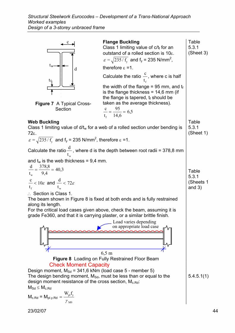
Figure 7 shows a typical cross-section for an IPE.
Structural Steelwork Eurocodes – Development of a Trans-National Approach Worked examples Design of a 3-storey unbraced frame
23/02/07 44
tw
t
d
c
f
Figure 7 A Typical Cross-
Section
Flange Buckling Class 1 limiting value of c/tf for an outstand of a rolled section is 10ε. ε = 235 / fy and fy = 235 N/mm2,
therefore ε =1.
Calculate the ratio ct f
, where c is half
the width of the flange = 95 mm, and tf is the flange thickness = 14,6 mm (if the flange is tapered, tf should be taken as the average thickness). ctf
= =95
14 66 5
,,
Table 5.3.1 (Sheet 3)
Web Buckling Class 1 limiting value of d/tw for a web of a rolled section under bending is 72ε. ε = 235 / fy and fy = 235 N/mm2, therefore ε =1.
Calculate the ratio dtw
, where d is the depth between root radii = 378,8 mm
and tw is the web thickness = 9,4 mm. dtw
= =378 89 4
40 3,,
,
ct
10f
< ε and dt
72w
< ε
∴ Section is Class 1.
Table 5.3.1 (Sheet 1) Table 5.3.1 (Sheets 1 and 3)
The beam shown in Figure 8 is fixed at both ends and is fully restrained along its length. For the critical load cases given above, check the beam, assuming it is grade Fe360, and that it is carrying plaster, or a similar brittle finish.
6,5 m
Load varies dependingon appropriate load case
Figure 8 Loading on Fully Restrained Floor Beam
Check Moment Capacity Design moment, MSd = 341,6 kNm (load case 5 - member 5) The design bending moment, MSd, must be less than or equal to the design moment resistance of the cross section, Mc.Rd: MSd ≤ Mc.Rd
Mc.Rd = Mpl.y.Rd =W fpl y
M0γ
5.4.5.1(1)
Structural Steelwork Eurocodes – Development of a Trans-National Approach Worked examples Design of a 3-storey unbraced frame
23/02/07 45
where Wpl is the plastic section modulus = 1702 cm3, fy is the yield strength = 235 N/mm2, and γM0 is the partial material safety factor = 1,1.
Table 3.1 5.1.1(2)
Therefore, Mpl.y.Rd =W fpl y
M0γ = 1702x10 x 235
1,1364 kNm
3
=
MSd = 341,6 kNm ≤ Mpl.y.Rd = 364 kNm Therefore the section is satisfactory.
Check Interaction of Maximum Axial Force and Bending Moment
Interaction case: Design moment, MSd = 341,6 kNm and design axial force, NSd = 28,1 kN (load case 5 - member 12) Lateral support to the floor beams is provided by the floor slabs, therefore there is no need to check for failure due to flexural or lateral torsional buckling.
A class 1 member subject to moment about the major axis only should satisfy the following:
MM
NN
Sd
pl.Rd
Sd
pl.Rd
+
≤2
1
Applied bending moment, MSd, = 341,6 kNm, design bending moment resistance of the section, Mpl.Rd = 364 kNm, applied axial load, NSd, = 28,1 kN, and
design compression resistance of the cross-section, Npl.Rd =Afy
M0γ
where A is the cross-sectional area of the section = 9880 mm2, fy is the yield strength = 235 N/mm2, and γM0 is the partial material safety factor = 1,1.
Therefore, Npl.Rd = =9880 x 235 kN
112111
,
Substituting into the above equation: 341 6 28 1 0 94
2, , ,x10
364x10x10
2111x10
6
6
3
3+
=
Therefore the section is satisfactory under combined axial load and bending moment
5.4.8.1(2) Table 3.1 5.1.1(2)
Lateral Torsional Buckling Although lateral restraint is provided by the floor slabs, it is necessary to check for lateral torsional buckling over the length of the beam which is in hogging (approximately 1,7 m). This is because the floor beams are restrained only by the upper flange, while the lower flange which is under compression, has no lateral restraint. As this is over such a short length of the beam, it is unlikely that this will be a critical condition. For completeness, however, the check is included in this worked example.
A class 1 section should satisfy the following: 5.5.4(2)

Structural Steelwork Eurocodes – Development of a Trans-National Approach Worked examples Design of a 3-storey unbraced frame
23/02/07 46
NAf
k MW f
Sd
z y M1
LT y.Sd
LT pl.y y M1χ γ χ γ/ /,+ ≤ 1 0
Applied axial force, NSd = 28,1 kN Determination of χz
Slenderness, λz = l/iz where l is taken as the length of beam in hogging, and i is the radius of gyration about the appropriate axis. Slenderness, λz = 1700 / 41,2 = 41,3
Non-dimensional slenderness, λλλ
βzz
1A
0,5=
where λ1 = 93,9ε = 93,9 x 1 = 93,9, and βA = 1 for class 1 members
Non-dimensional slenderness, λ z = =41 393 9
0 44,,
,
From Table 5.5.2, using buckling curve b, reduction factor, χz = 0,91
5.5.1.4 5.5.1.5(2) 5.5.1.2(1) 5.5.1.1(1) Table 5.5.3 Table 5.5.2
Cross-sectional area, A = 9880 mm2, Yield strength of the steel, fy = 235 N/ mm2, and Partial material safety factor for buckling resistance, γM1 = 1,1.
Table 3.1 5.1.1(2)
( )i I I
Wx10 x 791x10
1702x10 mmLt
z w
ply
6 9
3=
=
=2
0 25
2
0 25
16 76 46 3, ,
, , F.2.2(3)
a II
x1066,9x10
mmLtw
t
9
4=
=
=
0 5 0 5791 1087
, ,
F.2.2(1)
Structural Steelwork Eurocodes – Development of a Trans-National Approach Worked examples Design of a 3-storey unbraced frame
23/02/07 47
To Calculate kLT k N
AfLTLT Sd
z y
= −1 µχ
but kLT ≤ 1,0.
where µ λ β µLT z M.LT LT but = − ≤0 15 0 15 0 9, , , λ z = 0,44 βM.LT = 1,8 (ψ = 0) ∴µLT = (0,15 x 0,44 x 1,8) - 0,15 = -0,03
∴ = −−
=k x 28,1x10 x 9880 x 235LT
3
1 0 030 91
1 0( , ),
,
Applied moment, My.Sd = 341,6 kNm
5.5.4(2) 5.5.4(7) and Figure 5.5.3
To Calculate Reduction Factor, χLT The value of χLT can be determined from Table 5.5.2 for the appropriate value of the non-dimensional slenderness, λ LT .
λλλ
βLTLT
1w
0,5=
where λ1 = 93,9 ε = 93,9 x 1 = 93,9, βw = 1 for class 1 sections, and
( )λ LT
LT
1LT
L / i
CL / a
=
+
0 52 0 25
125 66
,
,
,
where L is the length = 1700 mm, iLT = 46,3 mm (from section properties), ψ = 0, k = 1,0, therefore C1 = 1,879, and aLT = 1087 mm (from section properties).
5.5.2(4) 5.5.2(5) 5.5.2(1) Equation F.15
Substituting into the above equation:
( )λ LT =
+
=1700 46 3
1 879 11700 1087
25 66
26 20 5
2 0 25/ ,
,/,
,,
,
∴ = = =λλλ
βLTLT
1w
0 5 0 526 293 9
1 0 0 28, ,,,
, ,
5.5.2(5)
Where the non-dimensional slenderness λ LT ≤ 0 4, , no allowance for lateral torsional buckling is necessary.
5.5.2(7)
Therefore, this section is satisfactory for lateral torsional buckling. Shear on Web
Design shear force, VSd = 255,2 kN (load case 5 - member 5) The shear resistance of the web must be checked. The design shear force, VSd, must be less than or equal to the design plastic shear resistance, Vpl.Rd: VSd ≤ Vpl.Rd
where Vpl.Rd is given by Af / 3
vy
M0γ
5.4.6

Structural Steelwork Eurocodes – Development of a Trans-National Approach Worked examples Design of a 3-storey unbraced frame
23/02/07 48
For rolled I and H sections loaded parallel to the web, shear area, Av = 1,04 h tw, fy is the yield strength = 235 N/mm2, and γM0 is the partial material safety factor = 1,1.
5.4.6(4) Table 3.1 5.1.1(2)
∴ =V1,04ht f
3xpl.Rdw y
M0γ = 1 04 543, x 450 x 9,4 x 235
3 x 1,1 kN=
This is greater than the shear on the section (255,2 kN). The section is satisfactory under shear.
A further check is sometimes required, especially when there are significant point loads, cantilevers or continuity, to ensure that the shear will not have a significant effect on the moment resistance. This check is carried out for the moment and shear at the same point. The moment resistance of the web is reduced if the shear is more than 50% of the shear resistance of the section. With a uniform load, the maximum moment and shear are not coincident and this check is not required for beams without web openings.
5.4.7(3)
Check Tension Resistance of Member Maximum applied tensile force, NSd = 31,5 kN (load case 2 - member 7) For members in axial tension, the design value of the tensile force, NSd must be less than the design tension resistance of the cross-section, Nt.Rd.
Nt.Rd = Npl.Rd = A fy
M0γ
where A is the cross-sectional area of the section = 9880 mm2, fy is the yield strength = 235 N/mm2, and γM0 is the partial material safety factor = 1,1.
Therefore N 9880 x 235 2110 kNpl.Rd = =11,
5.4.3(1) Table 3.1 5.1.1(2)
The design tension resistance of the cross-section, Nt.Rd = 2110 kN, is greater than the applied tensile force, NSd = 31,5 kN, therefore the section is OK.
Deflection Check For a plaster or similar brittle finish, the deflection limit is L/250 for δmax. Deflection checks are based on the serviceability loading.
Table 4.1 Figure 4.1
The maximum deflection for any floor beam is 6,2 mm which occurs under serviceability load case 4 at member 5.
Deflection limit for δ maxL
250 mm= = =
6500250
26
The actual deflection is less than the allowable deflection: 6,2 mm < 26 mm, therefore the section is OK.
Table 4.1
The calculated deflections are less than the limits, so no pre-camber is required.
4.3.2(2)
Structural Steelwork Eurocodes – Development of a Trans-National Approach Worked examples Design of a 3-storey unbraced frame
23/02/07 49
Summary The trial section IPE 450 is satisfactory.
Roof Beam The maximum moment any roof beam has to resist is 150,2 kNm at node P (member 19), under load case 5. The maximum compression force any roof beam has to resist is 55,8 kN (member 19) also under load case 5. The interaction of the axial force and bending moment will therefore be critical. The maximum shear force any roof beam has to resist is 130,4 kN at node P, under load case 2. The roof beams experience no tensile force.
IPE 360 Section properties: Depth, h = 360 mm, Width, b = 170 mm Web thickness, tw = 8,0 mm Flange thickness, tf = 12,7 mm Plastic modulus, Wpl = 1019 cm3
5.4.5.1
This notation conforms with Figure 1.1 in Eurocode 3: Part1.1. Classification of Cross-Section
Flange buckling Class 1 limiting value of c/tf for an outstand of a rolled section is 10ε. ε = 235 / fy and fy = 235 N/mm2, therefore ε =1.
Calculate the ratio ct f
, where c is half the width of the flange = 85 mm,
and tf is the flange thickness = 12,7 mm (if the flange is tapered, tf should be taken as the average thickness). ct f
= =85
12 76 7
,,
Table 5.3.1 (Sheet 3)
Web buckling Class 1 limiting value of d/tw for a web of a rolled section under bending is 72ε. ε = 235 / fy and fy = 235 N/mm2, therefore ε =1.
Calculate the ratio dtw
, where d is the depth between root radii = 298,6 mm
and tw is the web thickness = 8,0 mm. dtw
= =298 68 0
37 3,,
,
ct
10f
< ε and dt
72w
< ε
∴ Section is Class 1.
Table 5.3.1 (Sheet 1) Table 5.3.1 (Sheets 1 and 3)
For the critical load cases given above, check the beam, assuming it is grade Fe360, and that it is for a general roof.
Check Interaction of Maximum Axial Force and Bending Moment
Interaction case: Design moment, MSd = 150,2 kNm and design axial
Structural Steelwork Eurocodes – Development of a Trans-National Approach Worked examples Design of a 3-storey unbraced frame
23/02/07 50
force, NSd = 55,8 kN (load case 5 - member 19). There is no lateral support provided for the roof beams, therefore they must be checked for failure due to flexural and lateral torsional buckling.
Flexural Buckling A class 1 member subject to moment about the major axis only should satisfy the following:
NAf /
k MW f /
1,0sd
min y M1
y y.sd
pl.y y M1χ γ γ+ ≤
Applied axial force, NSd, = 55,8 kN
5.5.4(1)
To Calculate Reduction Factor, χmin The reduction factor χmin is the lesser of χy and χz, where χy and χz are the reduction factors from clause 5.5.1 for the y-y and z-z axes respectively.
Determination of χy The reduction factor χy depends on the slenderness about the y-y axis. Assuming that the connections at the beam ends are rigid, then the slenderness about the y-y axis is: λy = l/iy where l is taken as the system length, and i is the radius of gyration about the appropriate axis. Slenderness, λy = 6500 / 150 = 43,3 λ1 = 93,9ε = 93,9 x 1,0 = 93,9
Non-dimensional slenderness, λλλ
βyy
1A
0,5=
where βA = 1 for class 1 members
Non-dimensional slenderness, λ y = =43 393 9
0 46,,
,
From Table 5.5.2, using buckling curve a, the reduction factor, χy = 0,935
5.5.1.5 5.5.1.4 5.5.1.5(2) 5.5.1.2(1) 5.5.1.1(1) Table 5.5.3 Table 5.5.2
Determination of χz Slenderness, λz = l/iz where l is taken as the system length, and i is the radius of gyration about the appropriate axis. Slenderness, λz = 6500 / 37,9 = 171,5
Non-dimensional slenderness, λλλ
βzz
1A
0,5=
where βA = 1 for class 1 members
Non-dimensional slenderness, λ z = =171 593 9
1 8,,
,
From Table 5.5.2, using buckling curve b, reduction factor, χz = 0,2521
5.5.1.4 5.5.1.5(2) 5.5.1.2(1) 5.5.1.1(1) Table 5.5.3 Table 5.5.2
∴ Reduction factor, χmin = χz = 0,2521 A is the cross-sectional area = 7270 mm2, fy is the yield strength = 235 N/mm2, and γM1 is the partial material safety factor for buckling resistance = 1,1.
Table 3.1 5.1.1(2)
Structural Steelwork Eurocodes – Development of a Trans-National Approach Worked examples Design of a 3-storey unbraced frame
23/02/07 51
To Calculate ky
k 1NAfy
y sd
y y
= −µχ
but ky ≤ 1,5
where
µ λ βy y MYpl.y el.y
el.y
(2 4)W W
W= − +
− but µy ≤ 0,90
βMy is an equivalent uniform moment factor for flexural buckling
βMy = βM,ψ + M
MQ
MQ∆( ),β β ψ− M
where βM,ψ = 1,8 - 0,7ψ, and ψ = 0,47 Therefore βM,ψ = 1,8 - (0,7 x 0,47) = 1,47, MQ = 187 kNm, ∆M = 231 kNm, and βM,Q = 1,3. Therefore βMy = 1,47 + (187/231) x (1,3 - 1,47) = 1,33
µ y x 1,33 - 4) + 1019 - 904= = −0 46 2
9040 49, ( ,
k (-0,49) x 55,8x10 x 7270 x 235y
3
= − =10 935
1 02,
,
My.Sd is the design applied moment = 150,2 kNm, and Wpl.y is the plastic section modulus = 1019 x 103 mm3.
NAf /
k MW f /
1,0sd
min y M1
y y.sd
pl.y y M1χ γ γ+ ≤
55,8x100,2521 x 7270 x 235 / 1,1
x 150,2x101019x10 x 235 / 1,1
3 6
3+ =1 02 0 85, ,
Therefore this section is satisfactory for flexural buckling
5.5.4(1) 5.5.4(7) and Figure 5.5.3
Lateral Torsional Buckling A class 1 section should satisfy the following:
NAf
k MW f
Sd
z y M1
LT y.Sd
LT pl.y y M1χ γ χ γ/ /,+ ≤ 1 0
Applied axial force, NSd = 55,8 kN, Reduction factor, χz = 0,2521, Cross-sectional area, A = 7270 mm2, Yield strength of the steel, fy = 235 N/ mm2, and Partial material safety factor for buckling resistance, γM1 = 1,1.
5.5.4(2) Table 3.1 5.1.1(2)
( )i I I
Wx10 x 314x10
1019x10 mmLt
z w
ply
6 9
3=
=
=2
0 25
2
0 25
10 43 42 1, ,
, , F.2.2(3)
a II
x1037,3x10
mmLtw
t
9
4=
=
=
0 5 0 5314 917 5
, ,
, F.2.2(1)
Structural Steelwork Eurocodes – Development of a Trans-National Approach Worked examples Design of a 3-storey unbraced frame
23/02/07 52
To Calculate kLT k N
AfLTLT Sd
z y
= −1 µχ
but kLT ≤ 1,0.
where µ λ β µLT z M.LT LT but = − ≤0 15 0 15 0 9, , , λ z = 1,8 βM.LT = βM,ψ + (MQ/∆M)(βM,Q - βM,ψ), where βM,ψ = 1,8 - 0,7ψ, and ψ = 0,47, therefore βM,ψ = 1,8 - (0,7 x 0,47) = 1,47, MQ = 187 kNm, ∆M = 231 kNm, and βM,Q = 1,3. Therefore βM.LT = 1,47 + (187/231) (1,3 - 1,47) = 1,33. ∴µLT = (0,15 x 1,8 x 1,33) - 0,15 = 0,21.
∴ = − =k x 55,8x10 x 7270 x 235LT
3
1 0 210 2521
0 97,,
,
Applied moment, My.Sd = 150,1 kNm
5.5.4(2) 5.5.4(7) and Figure 5.5.3
To Calculate Reduction Factor, χLT The value of χLT can be determined from Table 5.5.2 for the appropriate value of the non-dimensional slenderness, λ LT .
λλλ
βLTLT
1w
0,5=
where λ1 = 93,9 ε = 93,9 x 1 = 93,9, βw = 1 for class 1 sections, and
( )λ LT
LT
1LT
L / i
CL / a
=
+
0 52 0 25
125 66
,
,
,
where L is the length = 6500 mm, iLT = 42,1 mm (from section properties), ψ = 0,47, k = 1,0, therefore C1 = 1,107, and aLT = 917,5 mm (from section properties).
5.5.2(4) 5.5.2(5) 5.5.2(1) Equation F.15 F.1.2(6)
Substituting into the above equation:
( )λ LT =
+
=6500 42 1
1107 16500 917 5
25 66
111 90 5
2 0 25/ ,
,/ ,,
,,
,
∴ = = =λλλ
βLTLT
1w
0 5 0 5111 993 9
1 0 1 2, ,,,
, ,
5.5.2(5)
Therefore, from Table 5.5.2, using buckling curve a (for rolled sections), the reduction factor, χLT = 0,53 The plastic section modulus, Wpl.y = 1019 x 103 mm3.
5.5.3(4), Table 5.5.3 Table 5.5.2
Structural Steelwork Eurocodes – Development of a Trans-National Approach Worked examples Design of a 3-storey unbraced frame
23/02/07 53
NAf
k MW f
Sd
z y M1
LT y.Sd
LT pl.y y M1χ γ χ γ/ /,+ ≤ 1 0
55 8 0 97 1 41 1, , ,x100,2521 x 7270 x 235 / 1,1
x 150,2x100,53 x 1019x10 x 235 / 1,1
3 6
3+ = ≥
5.5.4(2)
Therefore, this section is not satisfactory for lateral torsional buckling. It is highly unusual to have, in practice, unrestrained roof beams. It is, therefore, asssumed that beams/purlins are present at quarter points along the beam, reducing the unrestrained length to 1,625 m. The maximum change in moment occurs between the 3rd restraint and node P on member 19. When the check is carried out again, λ LT ≤ 0 4, , therefore no allowance for lateral torsional buckling is necessary.
5.5.2(7)
Shear on Web Design shear force, VSd = 130,4 kN (load case 2 - member 19) The shear resistance of the web must be checked. The design shear force, VSd, must be less than or equal to the design plastic shear resistance, Vpl.Rd: VSd ≤ Vpl.Rd
where Vpl.Rd is given by Af / 3
vy
M0γ
5.4.6
For rolled I and H sections loaded parallel to the web, shear area, Av = 1,04 h tw, fy is the yield strength = 235 N/mm2, and γM0 is the partial material safety factor = 1,1.
5.4.6(4) Table 3.1 5.1.1(2)
∴ =V1,04ht f
3xpl.Rdw y
M0γ = 1 04 369, x 360 x 8,0 x 235
3 x 1,1 kN=
This is greater than the shear on the section (130,4 kN), therefore this section is satisfactory under shear.
A further check is sometimes required, especially when there are significant point loads, cantilevers or continuity, to ensure that the shear will not have a significant effect on the moment resistance. This check is carried out for the moment and shear at the same point. The moment resistance of the web is reduced if the shear is more than 50% of the shear resistance of the section. With a uniform load, the maximum moment and shear are not coincident and this check is not required for beams without web openings.
5.4.7(3)
Deflection Check For a roof generally the deflection limit is L/200 for δmax. Deflection checks are based on the serviceability loading.
Table 4.1 Figure 4.1
The maximum deflection for any roof beam is 6,5 mm which occurs under serviceability load case 4 at member 19.
Deflection limit for δ maxL
200 mm= = =
6500200
32 5,
The actual deflection is less than the allowable deflection: 6,5 mm < 32,5 mm therefore the section is OK.
Table 4.1
The calculated deflections are less than the limits, so no pre-camber is 4.3.2(2)

Structural Steelwork Eurocodes – Development of a Trans-National Approach Worked examples Design of a 3-storey unbraced frame
23/02/07 54
required. Summary
The trial section IPE 360 is satisfactory.
Columns External Column
The maximum compression force any external column has to resist is 529 kN (member 4) under load case 5. The maximum moment any external column has to resist is 106 kNm at node H, under load case 7. The column is also subject to an axial load of 458,4 kN under this load case. However, the critical interaction case is likely to be under load case 5, with a maximum axial force of 529 kN and a bending moment of 103 kNm. It is this case that is likely to be critical. The maximum shear force any external column has to resist is 51,3 kN at member 11 under load case 5.
Section Properties All external columns are HE 220 B grade Fe360 h = 220 mm b = 220 mm tw = 9,5 mm tf = 16 mm d/tw = 16,0 c/tf = 6,9 A = 9100 mm2 Iy = 80,91 x 106 mm4 Iw = 295 x 109 mm6 Iz = 28,43 x 106 mm4 It = 76,6 x 104 mm4 Wpl.y = 827 x 103 mm3 Wel.y = 736 x 103 mm3 iy = 94,3 mm iz = 55,9 mm
( )i I I
Wx10 x 754x10
1283x10 mmLt
z w
ply
6 9
3=
=
=2
0 25
2
0 25
51 4 69 7, ,
, , F.2.2(3)
a II
x10124x10
mmLtw
t
9
4=
=
=
0 5 0 5754 779 8
, ,
, F.2.2(1)
All the above properties can be obtained from section property tables. Classification of Cross Section
This section is designed to withstand moments in addition to axial force. (Note that the section is always in compression.)
5.3
Flange (subject to compression) Class 1 limiting value of c/tf for an outstand of a rolled section is 10ε. ε = 235 / fy where fy = 235 N/mm2, ∴ ε = 1.
10ε = 10 x 1 = 10 From section properties, c/tf = 6,9
Table 5.3.1 (Sheet 3)
Web (subject to compression) Class 1 limiting value of d/tw for a web subject to compression only is 33ε. 33ε = 33 x 1 = 33 From section properties, d/tw = 16
Table 5.3.1 (Sheet 1)
c/tf ≤ 10ε and d/tw ≤ 33ε Therefore the section is Class 1.
Structural Steelwork Eurocodes – Development of a Trans-National Approach Worked examples Design of a 3-storey unbraced frame
23/02/07 55
Resistance of Cross-Section 5.4.4 It is highly unlikely that the resistance of the cross-section will be the critical case - it is generally the buckling resistance that governs the suitability of a cross-section. For the sake of completeness, the check is included in this worked example.
For members in axial compression, the design value of the compressive force, NSd, at each cross-section shall satisfy NSd ≤ Nc.Rd
5.4.4(1)
For a class 1 cross-section, the design compression resistance of the cross-section, Nc.Rd, may be determined as:
NAf
c.Rdy
M0
=γ
where A is cross-sectional area = 9100 mm2, fy is the yield strength = 235 N/mm2, and γM0 is the partial material safety factor = 1,1.
N 9100 x 235x10
kNc.Rd 3= =11
1944,
NSd = 529 kN, therefore Nsd < Nc.Rd. The section can resist the applied axial load.
5.4.4(2) Table 3.1 5.1.1(2)
Structural Steelwork Eurocodes – Development of a Trans-National Approach Worked examples Design of a 3-storey unbraced frame
23/02/07 56
Buckling Resistance of Member A class 1 member subject to combined bending and axial compression should be checked for the following modes of failure: • Flexural buckling (Clause 5.5.4(1)), and • Lateral Torsional Buckling (Clause 5.5.4(2)).
Flexural Buckling A class 1 member subject to moment about the major axis only should satisfy the following:
NA f /
k MW f /
Sd
min y M1
y y.Sd
pl.y y M1χ γ γ+ ≤ 1 0,
Applied axial force, NSd, = 529 kN
5.5.4(1)
To Calculate Reduction Factor, χmin The reduction factor χmin is the lesser of χy and χz, where χy and χz are the reduction factors from clause 5.5.1 for the y-y and z-z axes respectively.
Determination of χy The reduction factor χy depends on the slenderness about the y-y axis. The connections at the column base are effectively pinned, then the slenderness about the y-y axis is: λy = l/iy where l is equal to the system length and i is the radius of gyration about the appropriate axis. (Use the system length as using the amplified sway moment method. If using the effective length method, this is where the effective lengths would be greater than 1) Slenderness, λy = 3500 / 94,3 = 37,1 λ1 = 93,9ε = 93,9 x 1,0 = 93,9
Non-dimensional slenderness, λλλ
βyy
1A
0,5=
where βA = 1 for class 1 members
Non-dimensional slenderness, λ y = =37 193 9
0 4,,
,
From Table 5.5.2, using buckling curve b, the reduction factor, χy = 0,9261
5.5.1.5 5.5.1.4 5.5.1.5(1) 5.5.1.2(1) 5.5.1.1(1) Table 5.5.3 Table 5.5.2
Determination of χz Slenderness, λz = l/iz where l is equal to the system length and i is the radius of gyration about the appropriate axis. (Use the system length as using the amplified sway moment method. If using the effective length method, this is where the effective lengths would be greater than 1) Slenderness, λz = 3500 / 55,9 = 62,6
Non-dimensional slenderness, λλλ
βzz
1A
0,5=
where βA = 1 for class 1 members
5.5.1.4 5.5.1.5(2) 5.5.1.2(1) 5.5.1.1(1) Table
Structural Steelwork Eurocodes – Development of a Trans-National Approach Worked examples Design of a 3-storey unbraced frame
23/02/07 57
Non-dimensional slenderness, λ z = =62 693 9
0 67,,
,
From Table 5.5.2, using buckling curve c, reduction factor, χz = 0,73
5.5.3 Table 5.5.2
∴ Reduction factor, χmin = χz = 0,73 A is the cross-sectional area = 9100 mm2, fy is the yield strength = 235 N/mm2, and γM1 is the partial material safety factor for buckling resistance = 1,1.
Table 3.1 5.1.1(2)
Structural Steelwork Eurocodes – Development of a Trans-National Approach Worked examples Design of a 3-storey unbraced frame
23/02/07 58
To Calculate ky
k 1NAfy
y sd
y y
= −µχ
but ky ≤ 1,5
where
µ λ βy y Mypl.y el.y
el.y
W WW
= − +−
( )2 4 but µy ≤ 0,90
βMy is an equivalent uniform moment factor for flexural buckling (ψ = 0) = 1,8 - 0 = 1,8.
µ y =−
= −0 4 2 736 0 04, ( , x 1,8 - 4) + 827x10 x10736x10
3 3
3
( )∴ = −
−=k
x 529x10 x9100 x 235y
3
10 04
0 92611 01
,,
,
My.Sd is the design applied moment = 103 kNm, and Wpl.y is the plastic section modulus = 827 x 103 mm3.
NA f /
k MW f /
Sd
min y M1
y y.Sd
pl.y y M1χ γ γ+ ≤ 1 0,
529 1 01 0 96x100,73 x 9100 x 235 / 1,1
x 103x10827x10 x 235 / 1,1
3 6
3+ =, ,
Therefore the section is satisfactory for flexural buckling
5.5.4(1) 5.5.4(7) and Figure 5.5.3
Lateral Torsional Buckling A class 1 section should satisfy the following:
NAf
k MW f
Sd
z y M1
LT y.Sd
LT pl.y y M1χ γ χ γ/ /,+ ≤ 1 0
Applied axial force, NSd = 529 kN, Reduction factor, χz = 0,73, Cross-sectional area, A = 9100 mm2, Yield strength of the steel, fy = 235 N/ mm2, and Partial material safety factor for buckling resistance, γM1 = 1,1.
5.5.4(2) Table 3.1 5.1.1(2)
To Calculate kLT k N
AfLTLT Sd
z y
= −1 µχ
but kLT ≤ 1,0.
where µ λ β µLT z M.LT LT but = − ≤0 15 0 15 0 9, , , λ z = 0,67 βM.LT = 1,8 (ψ = 0) ∴µLT = (0,15 x 0,67 x 1,8) - 0,15 = 0,03
∴ = − =k x 529x10 x 9100 x 235LT
3
1 0 030 73
0 99,,
,
Applied moment, My.Sd = 102,8 kNm
5.5.4(2) 5.5.4(7) and Figure 5.5.3
To Calculate Reduction Factor, χLT The value of χLT can be determined from Table 5.5.2 for the appropriate value of the non-dimensional slenderness, λ LT .
5.5.2(4)
Structural Steelwork Eurocodes – Development of a Trans-National Approach Worked examples Design of a 3-storey unbraced frame
23/02/07 59
λλλ
βLTLT
1w
0,5=
where λ1 = 93,9 ε = 93,9 x 1 = 93,9, βw = 1 for class 1 sections, and
( )λ LT
LT
1LT
L / i
CL / a
=
+
0 52 0 25
125 66
,
,
,
where L is the length = 3500 mm, iLT = 69,7 mm (from section properties), ψ = 0, k = 1,0, therefore C1 = 1,879, and aLT = 779,8 mm (from section properties).
5.5.2(5) 5.5.2(1) Equation F.15
Substituting into the above equation:
( )λ LT =
+
=3500 69 7
1879 13500 779 8
25 66
40 10 5
2 0 25/ ,
,/ ,,
,,
,
∴ = = =λλλ
βLTLT
1w
0 5 0 540 193 9
1 0 0 43, ,,,
, ,
5.5.2(5)
Therefore, from Table 5.5.2, using buckling curve a (for rolled sections), the reduction factor, χLT = 0,94 The plastic section modulus, Wpl.y = 827 x 103 mm3.
5.5.3(4), Table 5.5.3 Table 5.5.2
NAf
k MW f
Sd
z y M1
LT y.Sd
LT pl.y y M1χ γ χ γ/ /,+ ≤ 1 0
529 0 99 0 98x100,73 x 9100 x 235 / 1,1
x 102,8x100,94 x 827x10 x 235 / 1,1
3 6
3+ =, ,
5.5.4(2)
Therefore, this section is satisfactory for lateral torsional buckling. This section is satisfactory for both flexural buckling and lateral torsional buckling.
Shear on Web Generally, a shear check on a column web would only be carried out if the structure is to be subjected to considerable seismic loading. For completeness, the check will be included in this worked example.
Design shear force, VSd = 51,3 kN (load case 5 - member 11) The shear resistance of the web must be checked. The design shear force, VSd, must be less than or equal to the design plastic shear resistance, Vpl.Rd: VSd ≤ Vpl.Rd
where Vpl.Rd is given by Af / 3
vy
M0γ
5.4.6
For rolled I and H sections loaded parallel to the web, shear area, Av = 1,04 h tw,
5.4.6(4)
Structural Steelwork Eurocodes – Development of a Trans-National Approach Worked examples Design of a 3-storey unbraced frame
23/02/07 60
fy is the yield strength = 235 N/mm2, and γM0 is the partial material safety factor = 1,1.
Table 3.1 5.1.1(2)
∴ =V1,04ht f
3xpl.Rdw y
M0γ = 1 04 268 1, , x 220 x 9,5 x 235
3 x 1,1 kN=
This is greater than the shear on the section (51,3 kN). The section is satisfactory under shear.
The column is satisfactory under all loading conditions.
Internal Column The maximum compression force any internal column has to resist is 1196 kN (member 2) under load case 2. The maximum moment any internal column has to resist is 142 kNm at node F, under load case 7. The column is also subject to an axial load of 961 kN under this load case. However, the critical interaction case is likely to be under load case 5, with an axial force of 1149,7 kN and a bending moment of 123,9 kNm. It is this case that is likely to be critical. The maximum shear force any internal column has to resist is 35,9 kN at member 2 under load case 7.
Section Properties All internal columns are HE 260 B grade Fe360 h = 260 mm b = 260 mm tw = 10 mm tf = 17,5 mm d/tw = 17,7 c/tf = 7,4 A = 1180 mm2 Iy = 149,2 x 106 mm4 Iw = 754 x 109 mm6 Iz = 51,4 x 106 mm4 It = 124 x 104 mm4 Wpl.y = 1283 x 103 mm3 Wel.y = 1148 x 103 mm3 iy = 112 mm iz = 65,8 mm
( )i I I
Wx10 x 754x10
1283x10 mmLt
z w
ply
6 9
3=
=
=2
0 25
2
0 25
51 4 69 7, ,
, , F.2.2(3)
a II
x10124x10
mmLtw
t
9
4=
=
=
0 5 0 5754 779 8
, ,
, F.2.2(1)
All the above properties can be obtained from section property tables.
Structural Steelwork Eurocodes – Development of a Trans-National Approach Worked examples Design of a 3-storey unbraced frame
23/02/07 61
Classification of Cross Section 5.3 Flange (subject to compression)
Class 1 limiting value of c/tf for an outstand of a rolled section is 10ε. ε = 235 / fy where fy = 235 N/mm2, therefore ε = 1. From section properties, c/tf = 7,4
Table 5.3.1 (Sheet 3)
Web (subject to compression) Class 1 limiting value of d/tw for a web subject to compression only is 33ε. From section properties, d/tw = 17,7 c/tf ≤ 10ε and d/tw ≤ 33ε Therefore the section is Class 1.
Table 5.3.1 (Sheet 1) Table 3.5.1 (Sheets 1 and 3)
Resistance of Cross-Section 5.4.4 It is highly unlikely that the resistance of the cross-section will be the critical case - it is generally the buckling resistance that governs the suitability of a cross-section. For the sake of completeness, the check is included in this worked example.
For members in axial compression, the design value of the compressive force, NSd, at each cross-section shall satisfy NSd ≤ Nc.Rd
5.4.4(1)
For a class 1 cross-section, the design compression resistance of the cross-section, Nc.Rd, may be determined as:
NAf
c.Rdy
M0
=γ
where A is cross-sectional area = 11800 mm2, fy is the yield strength = 235 N/mm2, and γM0 is the partial material safety factor = 1,1.
N 11800 x 235x10
kNc.Rd 3= =11
2521,
NSd = 1196 kN, therefore Nsd < Nc.Rd. The section can resist the applied axial load.
5.4.4(2) Table 3.1 5.1.1(2)

Structural Steelwork Eurocodes – Development of a Trans-National Approach Worked examples Design of a 3-storey unbraced frame
23/02/07 62
Buckling Resistance of Member A class 1 member subject to combined bending and axial compression should be checked for the following modes of failure: • Flexural buckling (Clause 5.5.4(1)), and • Lateral Torsional Buckling (Clause 5.5.4(2)).
Flexural Buckling A class 1 member subject to moment about the major axis only should satisfy the following:
NA f /
k MW f /
Sd
min y M1
y y.Sd
pl.y y M1χ γ γ+ ≤ 1 0,
Applied axial force, NSd, = 1149,7 kN
5.5.4(1)
To Calculate Reduction Factor, χmin The reduction factor χmin is the lesser of χy and χz, where χy and χz are the reduction factors from clause 5.5.1 for the y-y and z-z axes respectively.
Determination of χy The reduction factor χy depends on the slenderness about the y-y axis. The connections at the column base are effectively pinned, then the slenderness about the y-y axis is: λy = l/iy where l is equal to the system length and i is the radius of gyration about the appropriate axis. (Use the system length as using the amplified sway moment method. If using the effective length method, this is where the effective lengths would be greater than 1) Slenderness, λy = 3500 / 112 = 31,3 λ1 = 93,9ε = 93,9 x 1,0 = 93,9
Non-dimensional slenderness, λλλ
βyy
1A
0,5=
where βA = 1 for class 1 members
Non-dimensional slenderness, λ y = =31 393 9
0 33,,
,
From Table 5.5.2, using buckling curve b, the reduction factor, χy = 0,97
5.5.1.5 5.5.1.4 5.5.1.5(1) 5.5.1.2(1) 5.5.1.1(1) Table 5.5.3 Table 5.5.2
Determination of χz Slenderness, λz = l/iz where l is equal to the system length and i is the radius of gyration about the appropriate axis. (Use the system length as using the amplified sway moment method. If using the effective length method, this is where the effective lengths would be greater than 1) Slenderness, λz = 3500 / 65,8 = 53,2
Non-dimensional slenderness, λλλ
βzz
1A
0,5=
where βA = 1 for class 1 members
5.5.1.4 5.5.1.5(2) 5.5.1.2(1) 5.5.1.1(1) Table

Structural Steelwork Eurocodes – Development of a Trans-National Approach Worked examples Design of a 3-storey unbraced frame
23/02/07 63
Non-dimensional slenderness, λ z = =53 293 9
0 57,,
,
From Table 5.5.2, using buckling curve c, reduction factor, χz = 0,803
5.5.3 Table 5.5.2
∴ Reduction factor, χmin = χz = 0,803 A is the cross-sectional area = 11800 mm2, fy is the yield strength = 235 N/mm2, and γM1 is the partial material safety factor for buckling resistance = 1,1.
Table 3.1 5.1.1(2)
To Calculate ky
kNA fy
y Sd
y y
= −1µχ
but ky ≤ 1,5
where
µ λ βy y Mypl.y el.y
el.y
W WW
= − +−
( )2 4 but µy ≤ 0,90
βMy is an equivalent uniform moment factor for flexural buckling (ψ = 0) = 1,8 - 0 = 1,8.
µ y =−
= −0 33 2 1148 0 01, ( , x 1,8 - 4) + 1283x10 x101148x10
3 3
3
( )∴ = −
−=k
x 1154x10 x 11800 x 235y
3
10 01
0 971 0
,,
,
My.Sd is the design applied moment = 123,9 kNm, and Wpl.y is the plastic section modulus = 1283 x 103 mm3.
NA f /
k MW f /
Sd
min y M1
y y.Sd
pl.y y M1χ γ γ+ ≤ 1 0,
1149 7 1 0 1 02, , ,x100,803 x 11800 x 235 / 1,1
x 123,9x101283x10 x 235 / 1,1
3 6
3+ =
Therefore the section fails. The internal column section needs to be increased and the analysis and checks carried out on the modified structure.
5.5.4(1) 5.5.4(7) and Figure 5.5.3
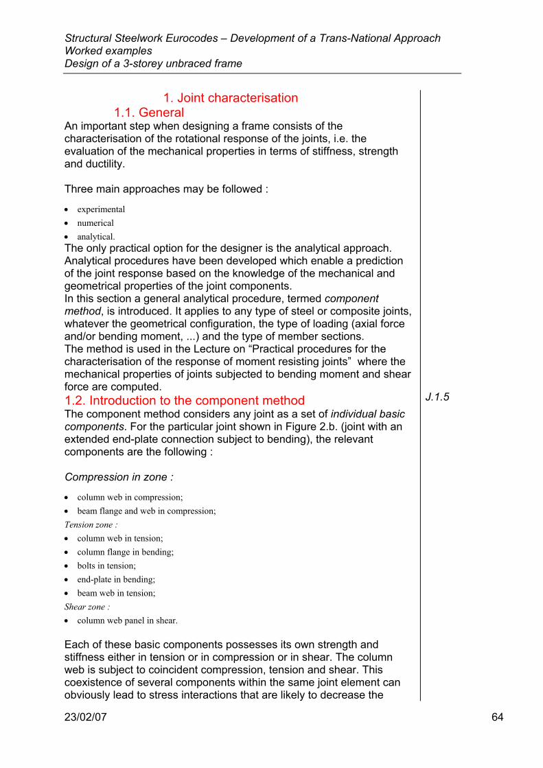
Structural Steelwork Eurocodes – Development of a Trans-National Approach Worked examples Design of a 3-storey unbraced frame
23/02/07 64
1. Joint characterisation 1.1. General
An important step when designing a frame consists of the characterisation of the rotational response of the joints, i.e. the evaluation of the mechanical properties in terms of stiffness, strength and ductility. Three main approaches may be followed :
• experimental • numerical • analytical. The only practical option for the designer is the analytical approach. Analytical procedures have been developed which enable a prediction of the joint response based on the knowledge of the mechanical and geometrical properties of the joint components. In this section a general analytical procedure, termed component method, is introduced. It applies to any type of steel or composite joints, whatever the geometrical configuration, the type of loading (axial force and/or bending moment, ...) and the type of member sections. The method is used in the Lecture on “Practical procedures for the characterisation of the response of moment resisting joints” where the mechanical properties of joints subjected to bending moment and shear force are computed. 1.2. Introduction to the component method The component method considers any joint as a set of individual basic components. For the particular joint shown in Figure 2.b. (joint with an extended end-plate connection subject to bending), the relevant components are the following : Compression in zone :
• column web in compression; • beam flange and web in compression; Tension zone : • column web in tension; • column flange in bending; • bolts in tension; • end-plate in bending; • beam web in tension; Shear zone : • column web panel in shear. Each of these basic components possesses its own strength and stiffness either in tension or in compression or in shear. The column web is subject to coincident compression, tension and shear. This coexistence of several components within the same joint element can obviously lead to stress interactions that are likely to decrease the
J.1.5
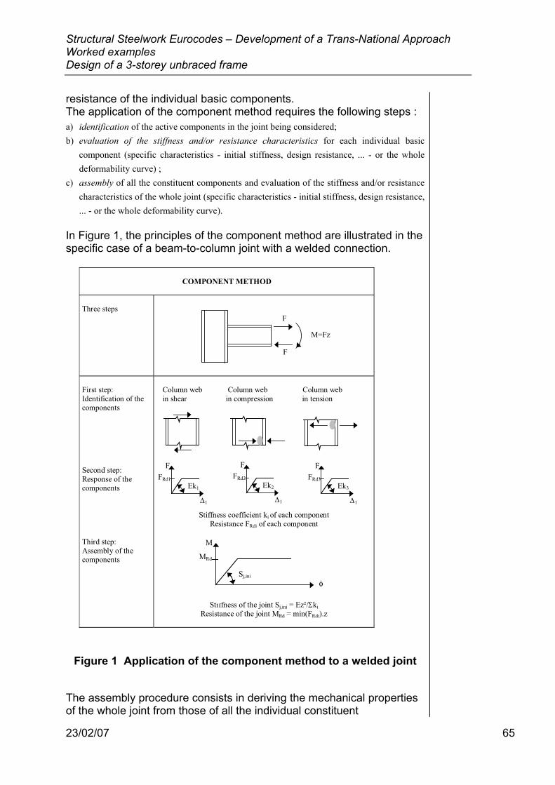
Structural Steelwork Eurocodes – Development of a Trans-National Approach Worked examples Design of a 3-storey unbraced frame
23/02/07 65
resistance of the individual basic components. The application of the component method requires the following steps : a) identification of the active components in the joint being considered; b) evaluation of the stiffness and/or resistance characteristics for each individual basic
component (specific characteristics - initial stiffness, design resistance, ... - or the whole deformability curve) ;
c) assembly of all the constituent components and evaluation of the stiffness and/or resistance characteristics of the whole joint (specific characteristics - initial stiffness, design resistance, ... - or the whole deformability curve).
In Figure 1, the principles of the component method are illustrated in the specific case of a beam-to-column joint with a welded connection.
COMPONENT METHOD
Three steps
First step:Identification of thecomponents
Second step:Response of thecomponents
Third step:Assembly of thecomponents
Column web Column web Column web in shear in compression in tension
Stiffness coefficient ki of each componentResistance FRdi of each component
Stiffness of the joint Sj,ini = Ez²/ΣkiResistance of the joint MRd = min(FRdi).z
F
F
M=Fz
F
∆1
FRd1Ek1
F
∆1
FRd2Ek2
F
∆1
FRd3Ek3
M
MRd
φSj,ini
Figure 1 Application of the component method to a welded joint
The assembly procedure consists in deriving the mechanical properties of the whole joint from those of all the individual constituent
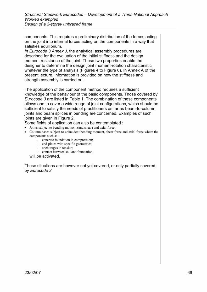
Structural Steelwork Eurocodes – Development of a Trans-National Approach Worked examples Design of a 3-storey unbraced frame
23/02/07 66
components. This requires a preliminary distribution of the forces acting on the joint into internal forces acting on the components in a way that satisfies equilibrium. In Eurocode 3 Annex J, the analytical assembly procedures are described for the evaluation of the initial stiffness and the design moment resistance of the joint. These two properties enable the designer to determine the design joint moment-rotation characteristic whatever the type of analysis (Figures 4 to Figure 6). In Annex A of the present lecture, information is provided on how the stiffness and strength assembly is carried out. The application of the component method requires a sufficient knowledge of the behaviour of the basic components. Those covered by Eurocode 3 are listed in Table 1. The combination of these components allows one to cover a wide range of joint configurations, which should be sufficient to satisfy the needs of practitioners as far as beam-to-column joints and beam splices in bending are concerned. Examples of such joints are given in Figure 2. Some fields of application can also be contemplated : • Joints subject to bending moment (and shear) and axial force; • Column bases subject to coincident bending moment, shear force and axial force where the
components such as : - concrete foundation in compression; - end-plates with specific geometries; - anchorages in tension; - contact between soil and foundation,
will be activated. These situations are however not yet covered, or only partially covered, by Eurocode 3.
Structural Steelwork Eurocodes – Development of a Trans-National Approach Worked examples Design of a 3-storey unbraced frame
23/02/07 67
N° Component
1 Column web panel in shear VSd
VSd
2 Column web in compression
Fc.Sd
3 Beam flange and web in compression
Fc.Sd
4 Column flange in bendingFt.Sd
5 Column web in tensionFt.Sd
6 End-plate in bending Ft.Sd
7 Beam web in tension Ft.Sd
8 Flange cleat in bending Ft.Sd
Table J.1
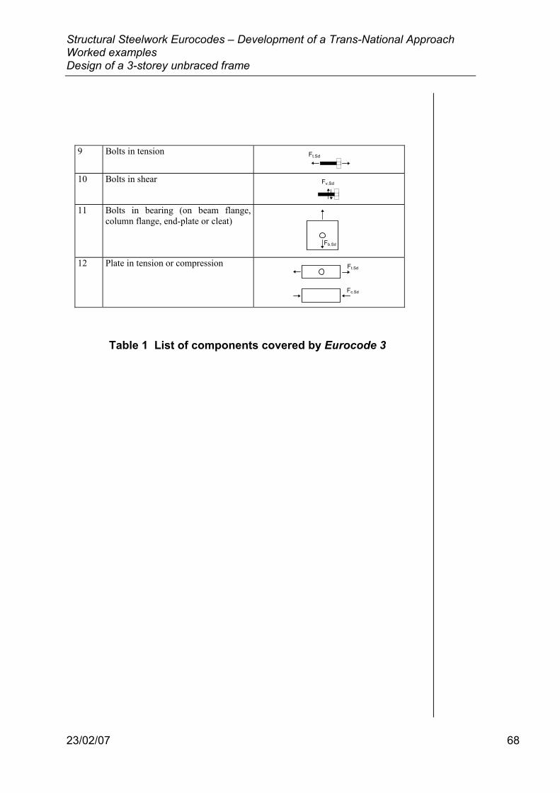
Structural Steelwork Eurocodes – Development of a Trans-National Approach Worked examples Design of a 3-storey unbraced frame
23/02/07 68
9 Bolts in tension Ft.Sd
10 Bolts in shear Fv.Sd
11 Bolts in bearing (on beam flange,column flange, end-plate or cleat)
Fb.Sd
12 Plate in tension or compression Ft.Sd
Fc.Sd
Table 1 List of components covered by Eurocode 3
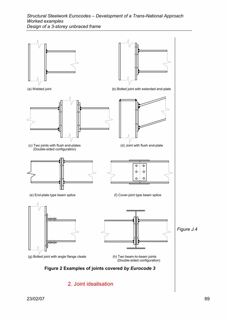
Structural Steelwork Eurocodes – Development of a Trans-National Approach Worked examples Design of a 3-storey unbraced frame
23/02/07 69
(a) Welded joint (b) Bolted joint with extended end-plate
(c) Two joints with flush end-plates (d) Joint with flush end-plate(Double-sided configuration)
(e) End-plate type beam splice (f) Cover-joint type beam splice
(g) Bolted joint with angle flange cleats (h) Two beam-to-beam joints (Double-sided configuration)
Figure 2 Examples of joints covered by Eurocode 3
2. Joint idealisation
Figure J.4
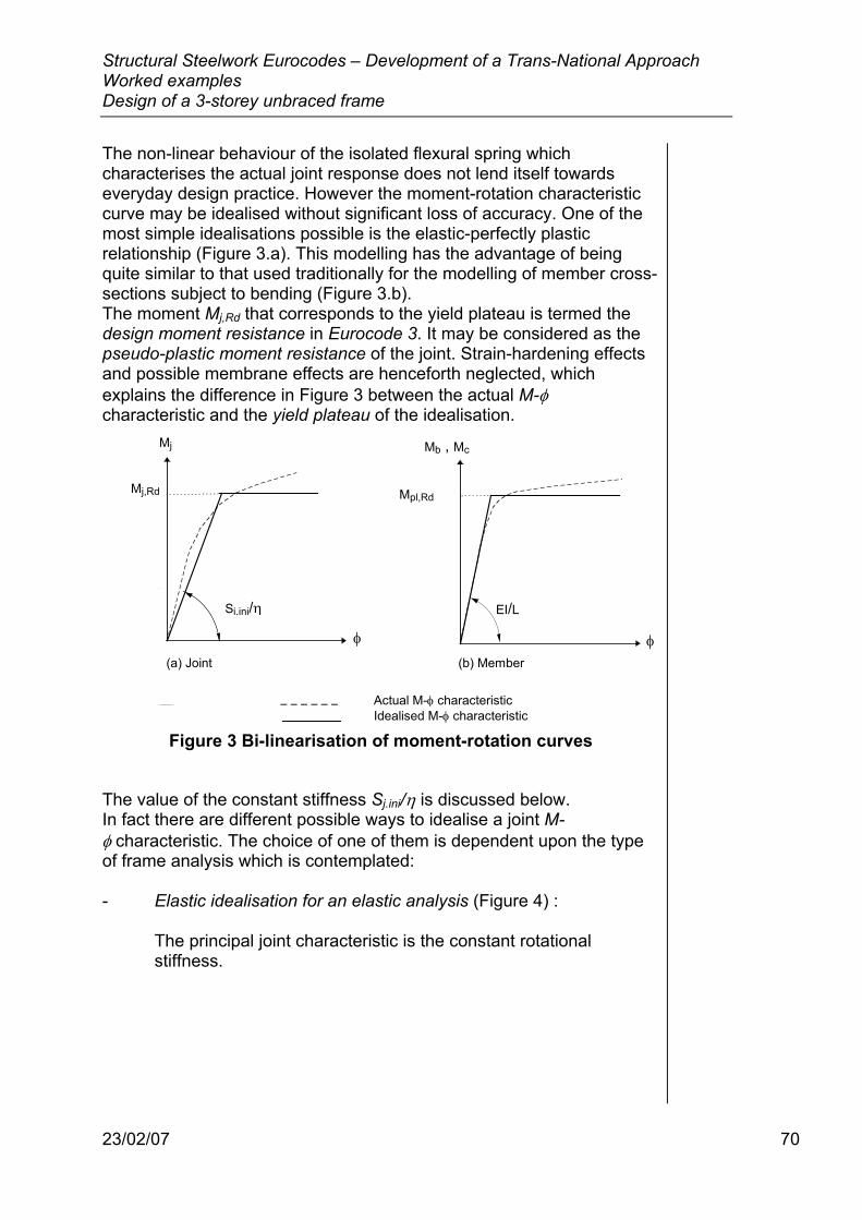
Structural Steelwork Eurocodes – Development of a Trans-National Approach Worked examples Design of a 3-storey unbraced frame
23/02/07 70
The non-linear behaviour of the isolated flexural spring which characterises the actual joint response does not lend itself towards everyday design practice. However the moment-rotation characteristic curve may be idealised without significant loss of accuracy. One of the most simple idealisations possible is the elastic-perfectly plastic relationship (Figure 3.a). This modelling has the advantage of being quite similar to that used traditionally for the modelling of member cross-sections subject to bending (Figure 3.b). The moment Mj,Rd that corresponds to the yield plateau is termed the design moment resistance in Eurocode 3. It may be considered as the pseudo-plastic moment resistance of the joint. Strain-hardening effects and possible membrane effects are henceforth neglected, which explains the difference in Figure 3 between the actual M-φ characteristic and the yield plateau of the idealisation.
Sj,ini/η
φ
Mj
Mj,Rd
EI/L
φ
Mb , Mc
Mpl,Rd
Actual M-φ characteristic Idealised M-φ characteristic
(a) Joint (b) Member
Figure 3 Bi-linearisation of moment-rotation curves
The value of the constant stiffness Sj.ini/η is discussed below. In fact there are different possible ways to idealise a joint M-φ characteristic. The choice of one of them is dependent upon the type of frame analysis which is contemplated: - Elastic idealisation for an elastic analysis (Figure 4) :
The principal joint characteristic is the constant rotational stiffness.
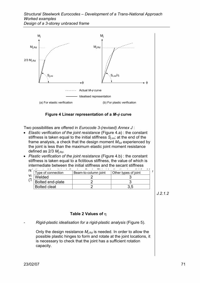
Structural Steelwork Eurocodes – Development of a Trans-National Approach Worked examples Design of a 3-storey unbraced frame
23/02/07 71
Sj,ini/η
φ
Mj
Mj,Rd
φ
Mj
Mj,Rd
2/3 Mj,Rd
Sj,ini
(a) For elastic verification (b) For plastic verification
Actual M-φ curve
Idealised representation
Figure 4 Linear representation of a M-φ curve
Two possibilities are offered in Eurocode 3-(revised) Annex J : • Elastic verification of the joint resistance (Figure 4.a) : the constant
stiffness is taken equal to the initial stiffness Sj.ini; at the end of the frame analysis, a check that the design moment MSd experienced by the joint is less than the maximum elastic joint moment resistance defined as 2/3 Mj,Rd.
• Plastic verification of the joint resistance (Figure 4.b) : the constant stiffness is taken equal to a fictitious stiffness, the value of which is intermediate between the initial stiffness and the secant stiffness relative to Mj,Rd; it is defined as Sj.ini/η. This idealisation is valid for MSd values less than or equal to Mj,Rd . The values of η are as follows (Table 2) :
Table 2 Values of η
- Rigid-plastic idealisation for a rigid-plastic analysis (Figure 5). Only the design resistance Mj,Rd is needed. In order to allow the possible plastic hinges to form and rotate at the joint locations, it is necessary to check that the joint has a sufficient rotation capacity.
J.2.1.2
Type of connection Beam-to-column joint Other types of joint Welded 2 3 Bolted end-plate 2 3 Bolted cleat 2 3,5
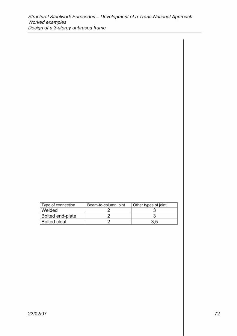
Structural Steelwork Eurocodes – Development of a Trans-National Approach Worked examples Design of a 3-storey unbraced frame
23/02/07 72
Type of connection Beam-to-column joint Other types of joint Welded 2 3 Bolted end-plate 2 3 Bolted cleat 2 3,5
Structural Steelwork Eurocodes – Development of a Trans-National Approach Worked examples Design of a 3-storey unbraced frame
23/02/07 73
Structural Steelwork Eurocodes – Development of a Trans-National Approach Worked examples Design of a 3-storey unbraced frame
23/02/07 74
TITRE 1
Structural Steelwork Eurocodes Development of
A Trans-national Approach Course: Eurocode 3 Module 7 : Introduction to the design of structural steelwork in accordance with the new Eurocodes
Lecture 3 : Introduction to EC3
Lecture 24 : Elastic Design of Portal Frames
Contents: 1 Frame geometry
2 Objectives and design strategy
3 Design assumptions and requirements
3.1 Structural bracing
3.2 Structural analysis and design of the members and joints
3.3 Materials
3.4 Partial safety factors on resistance
3.5 Loading
3.5.1 Basic loading
3.5.2 Basic load cases
3.5.3 Load combination cases 3.5.3.1 Ultimate load limit state combinations 3.5.3.2 Serviceability limit state requirements and load
combinations 3.5.4 Frame imperfections
4 Preliminary design
4.1 Member selection
4.2 Joint selection
5 Classification of the frame as non-sway
6 Design checks of members
7 Joint design and joint classification
7.1 Joint at the mid-span of the beam
7.2 Haunch joint at the beam-to-column joint
8 Conclusions

RAKENNUSTEKNIIKKA Olli Ilveskoski 30.08.2006 rev2 10.01.2007
23/02/07 75
75
Frame geometry The skeletal structure of a two bay pinned-base pitched portal frame with haunches for an industrial building is shown in Figure 1.
23,5m 23,5m
8m
1,5m
11,86m
Pitch 7,7°
Ridge EavesHaunch
Figure 1 Frame geometry
The outside dimensions of the building, including the cladding, are : Width : 48 m Height : 10 m Length : 60,5 m The portal frames, which are at 6,0 m intervals, have pinned-base 8 m high columns at centrelines of 23,5 m and have rafters sloped at 7,7° with a centreline ridge height of 9,5 m above ground level. Haunches are used for the joints of the rafters to the columns.
Objectives and design strategy The principal objective is to aim at global economy, without increasing the design effort in any significant manner. A traditional approach to the design of the structure including the joints is adopted initially. The traditional approach (see Chapter 2) is taken here to describe when the design of the joints is carried out once the global analysis and the design of the members have been accomplished. With such a separation of the task of designing the joints from those of analysing the structure and designing the structural members, it is possible that they are carried out by different people who may either be within the same company or, in some cases, may be part of another company. It has been usual for designers to put web stiffeners in the columns so as to justify the usual assumption that the rafter-to-column joints are rigid. It is recognised that eliminating these stiffeners simplifies the joint detailing and reduces fabrication costs. Although the removal of the stiffeners may have an impact on the member sizes required, in particular those of the columns, this is not always the case. Therefore, the strategy chosen here is to assume that economy can be achieved by the elimination of the web stiffeners in the columns. For the chosen structure, it is shown that the joint detailing can be simplified without any modification in the member sizes being required and without violating the initial assumption about the rigid nature of the joints. To achieve this end, the methods provided in Eurocode 3 for the design of the moment resistant joints are used.
ENV 1993-1-
RAKENNUSTEKNIIKKA Olli Ilveskoski 30.08.2006 rev2 10.01.2007
23/02/07 76
76
Design assumptions and requirements Structural bracing
The structure is unbraced in its plane. In the longitudinal direction of the building, i.e. normal to the plane of the portals, bracing is provided so that the purlins act as out-of-plane support points to the frame. It is therefore assumed that the top of each column is held in place against out-of-plane displacement and that the lateral support provided for the rafter is adequate to prevent lateral torsional buckling in it. Structural analysis and design of the members and joints A widely used elastic linear elastic analysis was adopted for the ultimate and serviceability limit states. Elastic analysis is particularly suited since plastic hinge behaviour in the members or the joints is not considered. At the final stage of the design, an allowance was made in the analysis for the increased section properties of the rafter over the length of the haunches. In accordance with the principle that elastic analysis is valid up to the formation of the first plastic hinge in the structure, the plastic design resistances of the member cross-sections and of the joints can be used for the verification of the ultimate limit states. The traditional assumption that joints are rigid is adopted. This assumption is verified. Materials Hot-rolled standard sections are used for the members. For the members, the haunches, the end-plates, the base-plates and any stiffeners, an S275 steel to EN 10025, with a yield strength of 275N/mm² and an ultimate strength of 430N/mm², is adopted. The bolts are Class 10.
Partial safety factors on resistance The values of the partial safety factors on resistance are as follows : γM0 = 1,1 for the resistance of cross-sections; γM1 = 1,1 for the buckling resistance of members; γM2 = 1,25 for the resistance of net sections; γMb = 1,25 for the resistance of bolts; γMw = 1,25 for the resistance of welds.
Loading
Basic loading
While the loads given are typical for a building of this type, they should be taken as indicative since the values currently required at the present time in different countries vary. These differences concern wind and snow l di i l
1
EN 10025 EN 20898-1EN 20898-2.
RAKENNUSTEKNIIKKA Olli Ilveskoski 30.08.2006 rev2 10.01.2007
23/02/07 77
77
loading mainly. Rather than apply the relevant parts of Eurocode 1-Basis of Design, which either are recently available or are still under discussion, the French loading standards were used to determine the design load intensities and their distribution on the structure. The building is situated in a rather exposed location for wind. For simplicity, the self-weight of the cladding plus that of its supporting purlins is considered to act as a uniformly distributed load on the frame perimeter.
ENV 1991-1-1
Permanent actions Variable action Permanent and variable
actions
Roofing self-
weight
Purlins: 0,15 kN/m Cladding with insulation: 0,2 kN/m2
Wind load Wind pressure of 0,965 kN/m² at 10 metres from the ground level.
Wall self-weight
Cladding with insulation: 0,2 kN/m2
Snow load Roof under 0,44 kN/m²
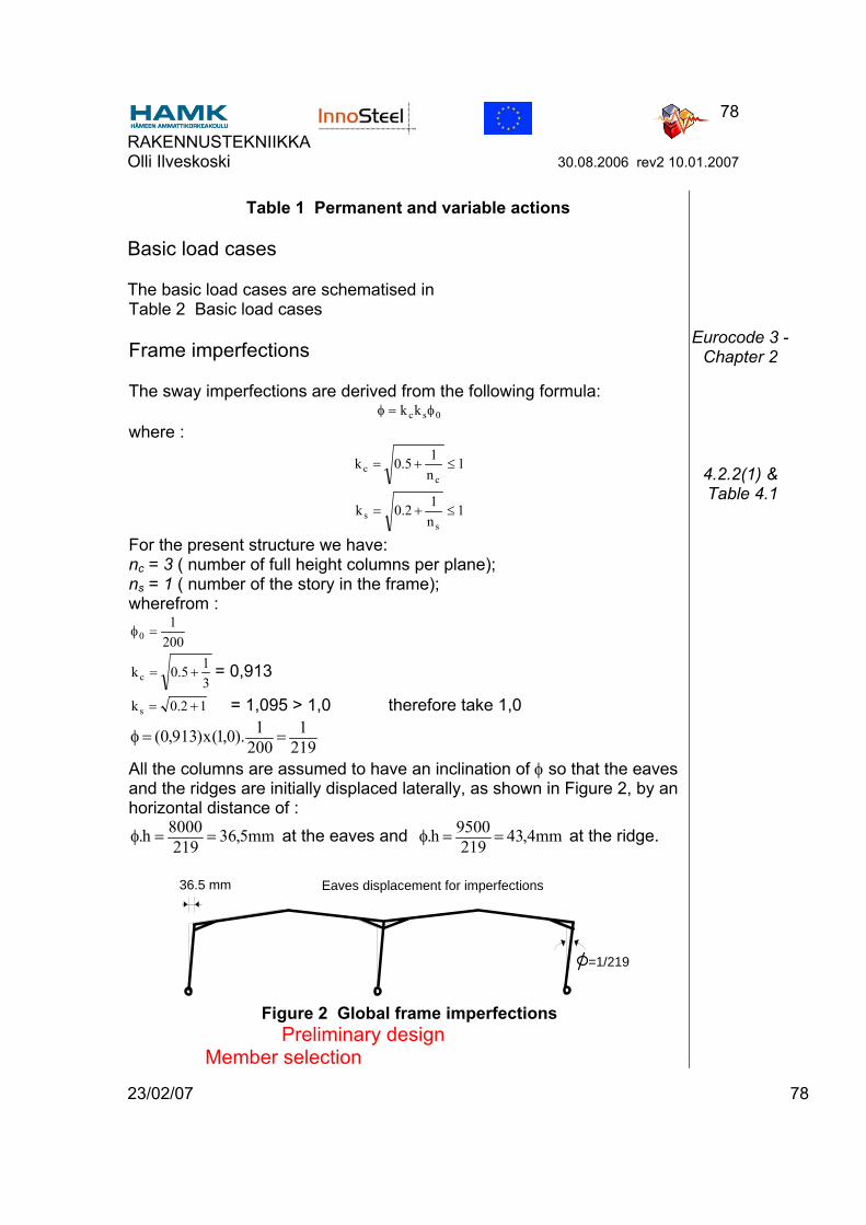
RAKENNUSTEKNIIKKA Olli Ilveskoski 30.08.2006 rev2 10.01.2007
23/02/07 78
78
Table 1 Permanent and variable actions
Basic load cases
The basic load cases are schematised in Table 2 Basic load cases
Frame imperfections
The sway imperfections are derived from the following formula: 0sckk φ=φ
where :
1n15.0kc
c ≤+=
1n12.0k
ss ≤+=
For the present structure we have: nc = 3 ( number of full height columns per plane); ns = 1 ( number of the story in the frame); wherefrom :
2001
0 =φ
315.0kc += = 0,913
12.0ks += = 1,095 > 1,0 therefore take 1,0
2191
2001).0,1(x)913,0( ==φ
All the columns are assumed to have an inclination of φ so that the eaves and the ridges are initially displaced laterally, as shown in Figure 2, by an horizontal distance of :
mm5,36219
8000h. ==φ at the eaves and mm4,432199500h. ==φ at the ridge.
Eaves displacement for imperfections36.5 mm
=1/219
Figure 2 Global frame imperfections
Preliminary design Member selection
Eurocode 3 -Chapter 2
4.2.2(1) & Table 4.1
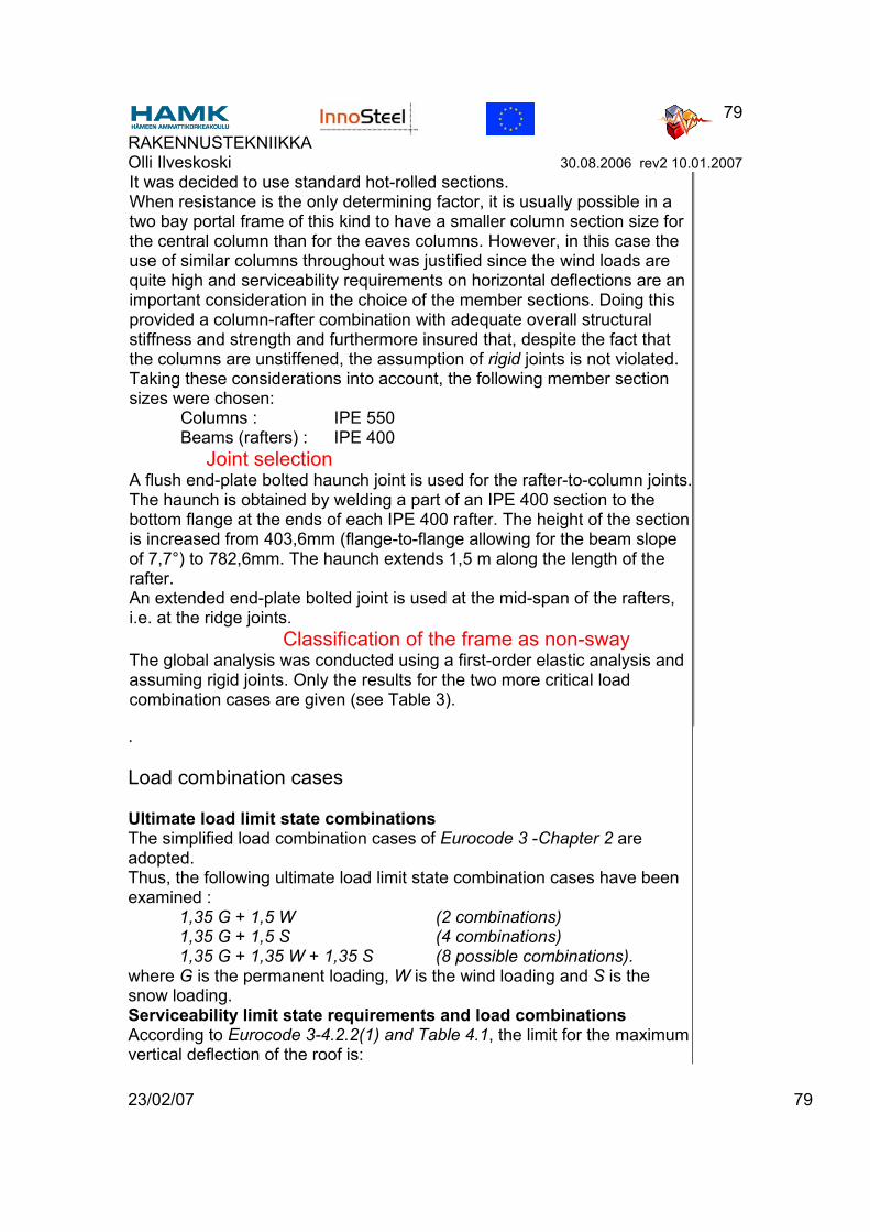
RAKENNUSTEKNIIKKA Olli Ilveskoski 30.08.2006 rev2 10.01.2007
23/02/07 79
79
It was decided to use standard hot-rolled sections. When resistance is the only determining factor, it is usually possible in a two bay portal frame of this kind to have a smaller column section size for the central column than for the eaves columns. However, in this case the use of similar columns throughout was justified since the wind loads are quite high and serviceability requirements on horizontal deflections are an important consideration in the choice of the member sections. Doing this provided a column-rafter combination with adequate overall structural stiffness and strength and furthermore insured that, despite the fact that the columns are unstiffened, the assumption of rigid joints is not violated. Taking these considerations into account, the following member section sizes were chosen: Columns : IPE 550 Beams (rafters) : IPE 400
Joint selection A flush end-plate bolted haunch joint is used for the rafter-to-column joints. The haunch is obtained by welding a part of an IPE 400 section to the bottom flange at the ends of each IPE 400 rafter. The height of the section is increased from 403,6mm (flange-to-flange allowing for the beam slope of 7,7°) to 782,6mm. The haunch extends 1,5 m along the length of the rafter. An extended end-plate bolted joint is used at the mid-span of the rafters, i.e. at the ridge joints.
Classification of the frame as non-sway The global analysis was conducted using a first-order elastic analysis and assuming rigid joints. Only the results for the two more critical load combination cases are given (see Table 3).
.
Load combination cases
Ultimate load limit state combinations The simplified load combination cases of Eurocode 3 -Chapter 2 are adopted. Thus, the following ultimate load limit state combination cases have been examined : 1,35 G + 1,5 W (2 combinations) 1,35 G + 1,5 S (4 combinations) 1,35 G + 1,35 W + 1,35 S (8 possible combinations). where G is the permanent loading, W is the wind loading and S is the snow loading. Serviceability limit state requirements and load combinations According to Eurocode 3-4.2.2(1) and Table 4.1, the limit for the maximum vertical deflection of the roof is:
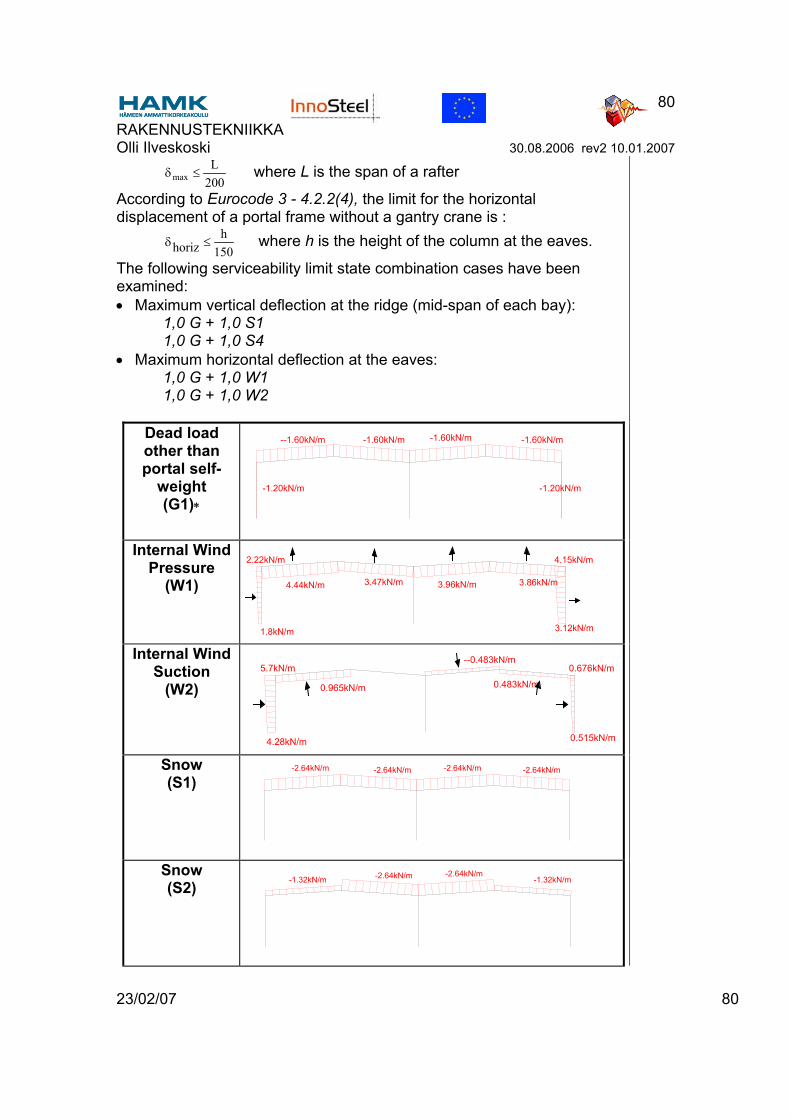
RAKENNUSTEKNIIKKA Olli Ilveskoski 30.08.2006 rev2 10.01.2007
23/02/07 80
80
200L
max ≤δ where L is the span of a rafter
According to Eurocode 3 - 4.2.2(4), the limit for the horizontal displacement of a portal frame without a gantry crane is :
150h
horiz ≤δ where h is the height of the column at the eaves.
The following serviceability limit state combination cases have been examined: • Maximum vertical deflection at the ridge (mid-span of each bay): 1,0 G + 1,0 S1 1,0 G + 1,0 S4 • Maximum horizontal deflection at the eaves: 1,0 G + 1,0 W1 1,0 G + 1,0 W2
Dead load other than portal self-
weight (G1)∗
-1.60kN/m --1.60kN/m -1.60kN/m -1.60kN/m
-1.20kN/m -1.20kN/m
Internal Wind Pressure
(W1) 4.44kN/m 3.47kN/m 3.96kN/m 3.86kN/m
1.8kN/m
2.22kN/m
3.12kN/m
4.15kN/m
Internal Wind Suction
(W2) 0.965kN/m
--0.483kN/m
0.483kN/m
4.28kN/m
5.7kN/m
0.515kN/m
0.676kN/m
Snow (S1)
-2.64kN/m -2.64kN/m -2.64kN/m -2.64kN/m
Snow (S2) -1.32kN/m -2.64kN/m -2.64kN/m
-1.32kN/m

RAKENNUSTEKNIIKKA Olli Ilveskoski 30.08.2006 rev2 10.01.2007
23/02/07 81
81
Snow (S3) -1.32kN/m
-5.40kN/m
-1.32kN/m
Snow (S4)
-5.40kN/m -5.40kN/m -5.40kN/m
∗ The self-weight of the frame structural members(G2) is added to the self-weight from the cladding and purlins (G1) to give the total dead load (G).

RAKENNUSTEKNIIKKA Olli Ilveskoski 30.08.2006 rev2 10.01.2007
23/02/07 82
82
Table 2 Basic load cases
Frame imperfections
The sway imperfections are derived from the following formula: 0sckk φ=φ
where :
1n15.0kc
c ≤+=
1n12.0k
ss ≤+=
For the present structure we have: nc = 3 ( number of full height columns per plane); ns = 1 ( number of the story in the frame); wherefrom :
2001
0 =φ
315.0kc += = 0,913
12.0ks += = 1,095 > 1,0 therefore take 1,0
2191
2001).0,1(x)913,0( ==φ
All the columns are assumed to have an inclination of φ so that the eaves and the ridges are initially displaced laterally, as shown in Figure 2, by an horizontal distance of :
mm5,36219
8000h. ==φ at the eaves and mm4,432199500h. ==φ at the ridge.
Eaves displacement for imperfections36.5 mm
=1/219
Figure 2 Global frame imperfections
Preliminary design Member selection
It was decided to use standard hot-rolled sections. When resistance is the only determining factor, it is usually possible in a two bay portal frame of this kind to have a smaller column section size for the central column than for the eaves columns. However, in this case the use of similar columns throughout was justified since the wind loads are
5.2.4.3(1)
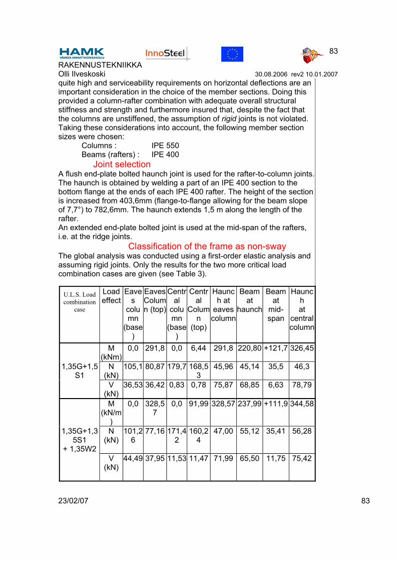
RAKENNUSTEKNIIKKA Olli Ilveskoski 30.08.2006 rev2 10.01.2007
23/02/07 83
83
quite high and serviceability requirements on horizontal deflections are an important consideration in the choice of the member sections. Doing this provided a column-rafter combination with adequate overall structural stiffness and strength and furthermore insured that, despite the fact that the columns are unstiffened, the assumption of rigid joints is not violated. Taking these considerations into account, the following member section sizes were chosen: Columns : IPE 550 Beams (rafters) : IPE 400
Joint selection A flush end-plate bolted haunch joint is used for the rafter-to-column joints. The haunch is obtained by welding a part of an IPE 400 section to the bottom flange at the ends of each IPE 400 rafter. The height of the section is increased from 403,6mm (flange-to-flange allowing for the beam slope of 7,7°) to 782,6mm. The haunch extends 1,5 m along the length of the rafter. An extended end-plate bolted joint is used at the mid-span of the rafters, i.e. at the ridge joints.
Classification of the frame as non-sway The global analysis was conducted using a first-order elastic analysis and assuming rigid joints. Only the results for the two more critical load combination cases are given (see Table 3).
U.L.S. Load combination
case
Load effect
Eaves
column
(base)
Eaves Column (top)
Central
column
(base)
Central
Column
(top)
Haunch at
eaves column
Beam at
haunch
Beam at
mid-span
Haunch at
central column
M (kNm)
0,0 291,8 0,0 6,44 291,8 220,80 +121,7 326,45
1,35G+1,5S1
N (kN)
105,1 80,87 179,7 168,53
45,96 45,14 35,5 46,3
V (kN)
36,53 36,42 0,83 0,78 75,87 68,85 6,63 78,79
M (kN/m
)
0,0 328,57
0,0 91,99 328,57 237,99 +111,9 344,58
1,35G+1,35S1
+ 1,35W2
N (kN)
101,26
77,16 171,42
160,24
47,00 55,12 35,41 56,28
V (kN)
44,49 37,95 11,53 11,47 71,99 65,50 11,75 75,42
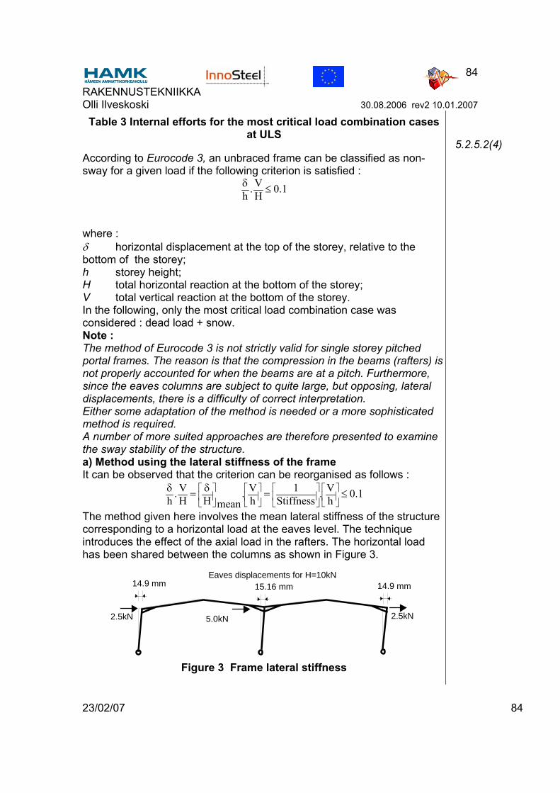
RAKENNUSTEKNIIKKA Olli Ilveskoski 30.08.2006 rev2 10.01.2007
23/02/07 84
84
Table 3 Internal efforts for the most critical load combination cases at ULS
According to Eurocode 3, an unbraced frame can be classified as non-sway for a given load if the following criterion is satisfied :
1.0HV.
h≤δ
where : δ horizontal displacement at the top of the storey, relative to the bottom of the storey; h storey height; H total horizontal reaction at the bottom of the storey; V total vertical reaction at the bottom of the storey. In the following, only the most critical load combination case was considered : dead load + snow. Note : The method of Eurocode 3 is not strictly valid for single storey pitched portal frames. The reason is that the compression in the beams (rafters) is not properly accounted for when the beams are at a pitch. Furthermore, since the eaves columns are subject to quite large, but opposing, lateral displacements, there is a difficulty of correct interpretation. Either some adaptation of the method is needed or a more sophisticated method is required. A number of more suited approaches are therefore presented to examine the sway stability of the structure. a) Method using the lateral stiffness of the frame It can be observed that the criterion can be reorganised as follows :
1.0hV.
Stiffness1
hV.
meanHHV.
h≤=δ=δ
The method given here involves the mean lateral stiffness of the structure corresponding to a horizontal load at the eaves level. The technique introduces the effect of the axial load in the rafters. The horizontal load has been shared between the columns as shown in Figure 3.
Eaves displacements for H=10kN14.9 mm 15.16 mm 14.9 mm
2.5kN 2.5kN5.0kN
Figure 3 Frame lateral stiffness
5.2.5.2(4)
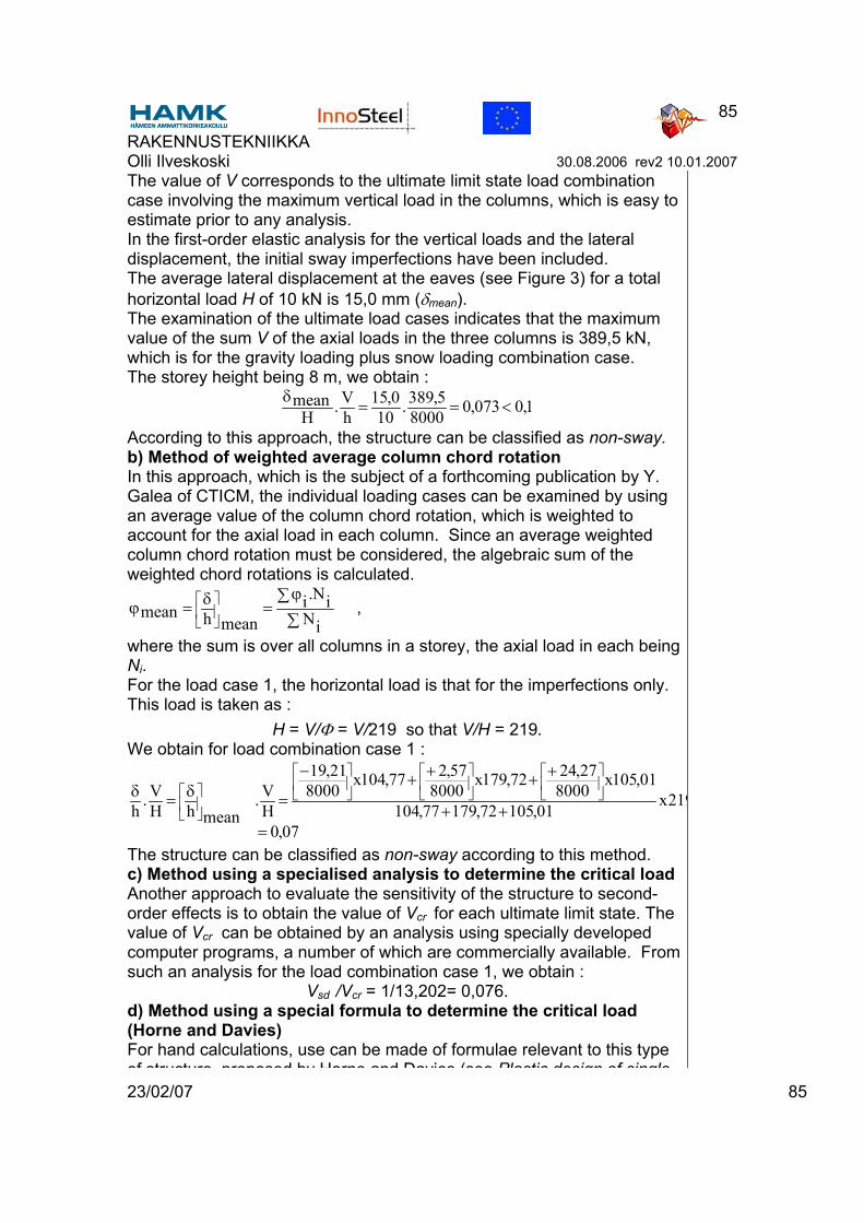
RAKENNUSTEKNIIKKA Olli Ilveskoski 30.08.2006 rev2 10.01.2007
23/02/07 85
85
The value of V corresponds to the ultimate limit state load combination case involving the maximum vertical load in the columns, which is easy to estimate prior to any analysis. In the first-order elastic analysis for the vertical loads and the lateral displacement, the initial sway imperfections have been included. The average lateral displacement at the eaves (see Figure 3) for a total horizontal load H of 10 kN is 15,0 mm (δmean). The examination of the ultimate load cases indicates that the maximum value of the sum V of the axial loads in the three columns is 389,5 kN, which is for the gravity loading plus snow loading combination case. The storey height being 8 m, we obtain :
1,0073,080005,389.10
0,15hV.H
mean <==δ
According to this approach, the structure can be classified as non-sway. b) Method of weighted average column chord rotation In this approach, which is the subject of a forthcoming publication by Y. Galea of CTICM, the individual loading cases can be examined by using an average value of the column chord rotation, which is weighted to account for the axial load in each column. Since an average weighted column chord rotation must be considered, the algebraic sum of the weighted chord rotations is calculated.
∑∑ ϕ
=δ=ϕ
iNiN.i
meanhmean ,
where the sum is over all columns in a storey, the axial load in each being Ni. For the load case 1, the horizontal load is that for the imperfections only. This load is taken as :
H = V/Φ = V/219 so that V/H = 219. We obtain for load combination case 1 :
07,0
219x01,10572,17977,104
01,105x8000
27,2472,179x8000
57,277,104x8000
21,19
HV.
meanhHV.
h=
++
++++−
=δ=δ
The structure can be classified as non-sway according to this method. c) Method using a specialised analysis to determine the critical load Another approach to evaluate the sensitivity of the structure to second-order effects is to obtain the value of Vcr for each ultimate limit state. The value of Vcr can be obtained by an analysis using specially developed computer programs, a number of which are commercially available. From such an analysis for the load combination case 1, we obtain :
Vsd /Vcr = 1/13,202= 0,076. d) Method using a special formula to determine the critical load (Horne and Davies) For hand calculations, use can be made of formulae relevant to this type of structure proposed by Horne and Davies (see Plastic design of single
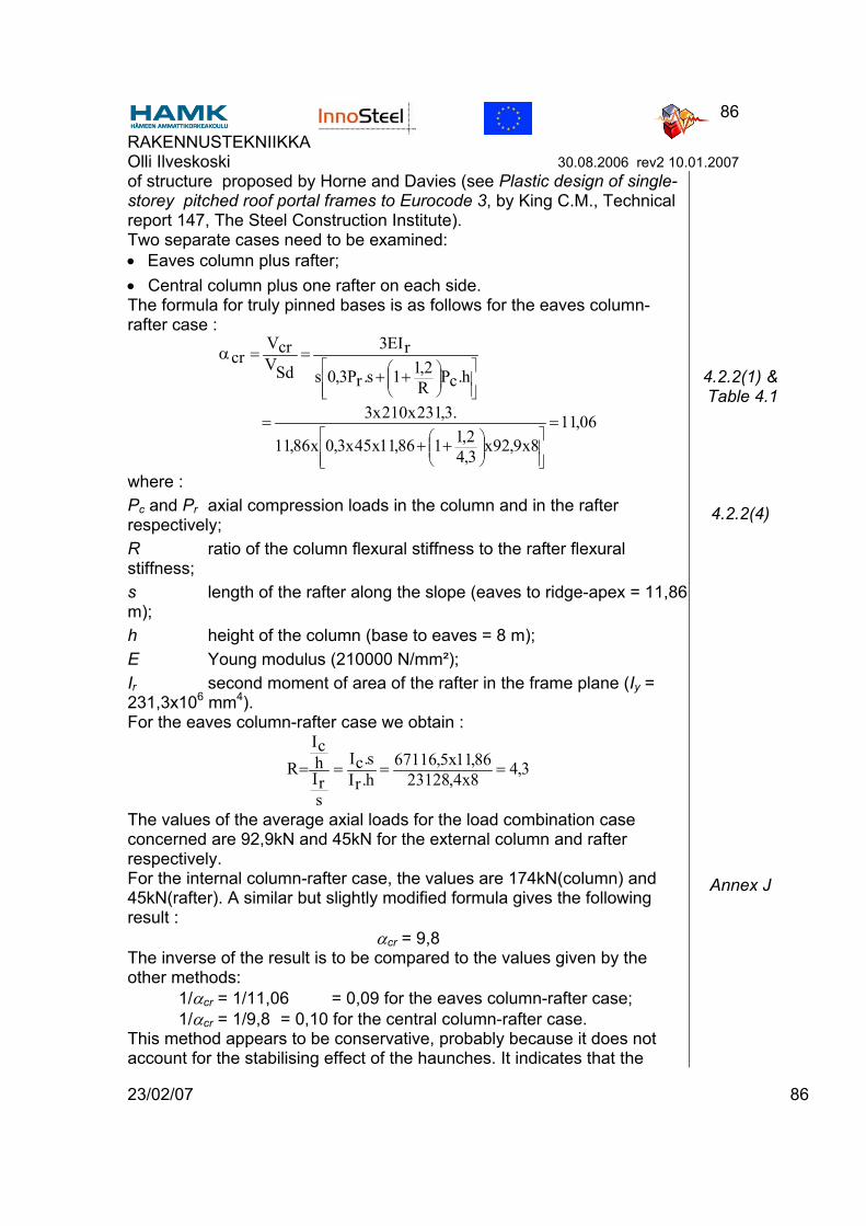
RAKENNUSTEKNIIKKA Olli Ilveskoski 30.08.2006 rev2 10.01.2007
23/02/07 86
86
of structure proposed by Horne and Davies (see Plastic design of single-storey pitched roof portal frames to Eurocode 3, by King C.M., Technical report 147, The Steel Construction Institute). Two separate cases need to be examined: • Eaves column plus rafter; • Central column plus one rafter on each side. The formula for truly pinned bases is as follows for the eaves column-rafter case :
06,118x9,92x
3,42,1186,11x45x3,0x86,11
.3,231x210x3
h.cPR2,11s.rP3,0s
rEI3
SdVcrV
cr
=++
=
++==α
where : Pc and Pr axial compression loads in the column and in the rafter respectively; R ratio of the column flexural stiffness to the rafter flexural stiffness; s length of the rafter along the slope (eaves to ridge-apex = 11,86 m); h height of the column (base to eaves = 8 m); E Young modulus (210000 N/mm²); Ir second moment of area of the rafter in the frame plane (Iy = 231,3x106 mm4). For the eaves column-rafter case we obtain :
3,48x4,2312886,11x5,67116
h.rIs.cI
srIhcI
R ====
The values of the average axial loads for the load combination case concerned are 92,9kN and 45kN for the external column and rafter respectively. For the internal column-rafter case, the values are 174kN(column) and 45kN(rafter). A similar but slightly modified formula gives the following result :
αcr = 9,8 The inverse of the result is to be compared to the values given by the other methods: 1/αcr = 1/11,06 = 0,09 for the eaves column-rafter case; 1/αcr = 1/9,8 = 0,10 for the central column-rafter case. This method appears to be conservative, probably because it does not account for the stabilising effect of the haunches. It indicates that the
4.2.2(1) & Table 4.1
4.2.2(4)
Annex J
RAKENNUSTEKNIIKKA Olli Ilveskoski 30.08.2006 rev2 10.01.2007
23/02/07 87
87
structure cannot be strictly considered as non-sway; however since the result is close to the required criteria and because the method is conservative, it can be accepted to allow a non-sway classification. e) Second-order elastic analysis to integrate the second-order effects The last approach possible is to carry out a second-order elastic analysis. The structure has been thus analysed and the results show that second-order effects are negligible, thus confirming the validity of the methods of assessment used above.
Design checks of members According to Eurocode 3, the limit for the maximum vertical deflection of the roof under the service loads is:
mm5,11720023500
200L
max ==≤δ
Since the vertical deflection of 61,25 mm < 117,5 mm, the condition is satisfied. According to Eurocode 3, the limit for the horizontal displacement, under the service loads, of a portal frame without a gantry crane is :
mm3,531508000
150h
horiz ==≤δ
Since the maximum lateral displacement is 42,35 mm < 53,3 mm, the condition is satisfied. Detailed verifications at the ultimate limit state (sections and lateral stability of rafters, sections and stability of columns) have been carried out using the Eurocode 3-TOOLS suite of programs. These calculations show that the design is fully satisfactory. In order to reduce the volume of this worked example and not to duplicate checks that have yet been illustrated in the two previous examples, the detailed results are not reproduced here.
Joint design and joint classification The joints are designed according to Eurocode 3-(revised) Annex J.
Joint at the mid-span of the beam The joint at the ridge is subjected to the following extreme design loading situation: Load
combination case
Load effects
Positive moment MSd (kNm) : 121,77
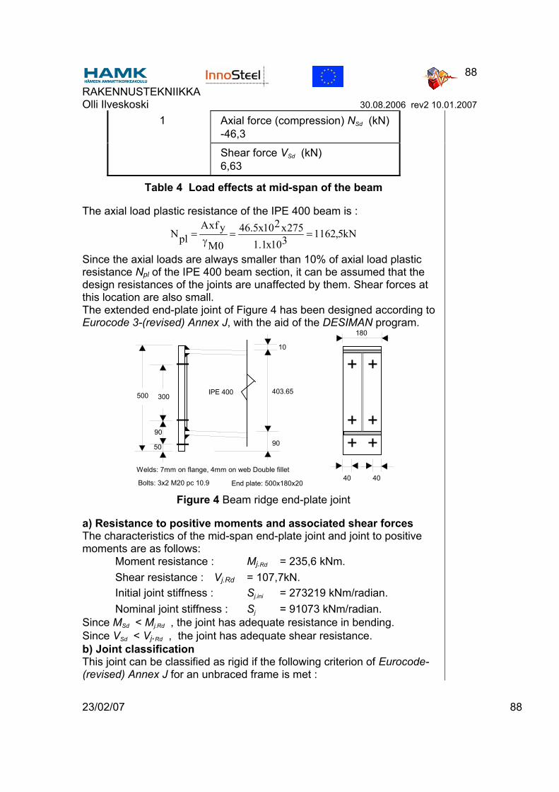
RAKENNUSTEKNIIKKA Olli Ilveskoski 30.08.2006 rev2 10.01.2007
23/02/07 88
88
1 Axial force (compression) NSd (kN) -46,3
Shear force VSd (kN) 6,63
Table 4 Load effects at mid-span of the beam
The axial load plastic resistance of the IPE 400 beam is :
kN5,1162310x1.1275x210x5.46
0M
yfxAplN ==
γ=
Since the axial loads are always smaller than 10% of axial load plastic resistance Npl of the IPE 400 beam section, it can be assumed that the design resistances of the joints are unaffected by them. Shear forces at this location are also small. The extended end-plate joint of Figure 4 has been designed according to Eurocode 3-(revised) Annex J, with the aid of the DESIMAN program.
500
50
90
10
403.65
90
40 40
180
IPE 400300
Welds: 7mm on flange, 4mm on web Double fillet
Bolts: 3x2 M20 pc 10.9 End plate: 500x180x20 Figure 4 Beam ridge end-plate joint
a) Resistance to positive moments and associated shear forces The characteristics of the mid-span end-plate joint and joint to positive moments are as follows: Moment resistance : Mj.Rd = 235,6 kNm. Shear resistance : Vj.Rd = 107,7kN. Initial joint stiffness : Sj.ini = 273219 kNm/radian. Nominal joint stiffness : Sj = 91073 kNm/radian. Since MSd < Mj.Rd , the joint has adequate resistance in bending. Since VSd < Vj.Rd , the joint has adequate shear resistance. b) Joint classification This joint can be classified as rigid if the following criterion of Eurocode-(revised) Annex J for an unbraced frame is met :
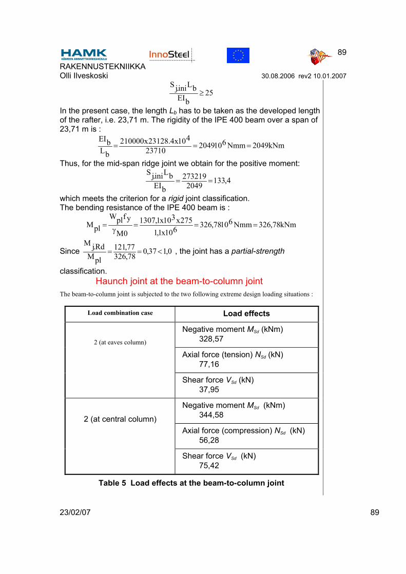
RAKENNUSTEKNIIKKA Olli Ilveskoski 30.08.2006 rev2 10.01.2007
23/02/07 89
89
25bEI
bLini.jS≥
In the present case, the length Lb has to be taken as the developed length of the rafter, i.e. 23,71 m. The rigidity of the IPE 400 beam over a span of 23,71 m is :
kNm2049Nmm610204923710410x4.23128x210000
bLbEI
===
Thus, for the mid-span ridge joint we obtain for the positive moment:
4,1332049273219
bEIbLini.jS
==
which meets the criterion for a rigid joint classification. The bending resistance of the IPE 400 beam is :
Nmk78,326Nmm61078,326610x1,1275x310x1,1307
0M
yfplWplM ===
γ=
Since 0,137,078,32677,121
plMRd.jM
<== , the joint has a partial-strength
classification. Haunch joint at the beam-to-column joint
The beam-to-column joint is subjected to the two following extreme design loading situations :
Load combination case Load effects
Negative moment MSd (kNm) 328,57
Axial force (tension) NSd (kN) 77,16
2 (at eaves column)
Shear force VSd (kN) 37,95
Negative moment MSd (kNm) 344,58
Axial force (compression) NSd (kN) 56,28
2 (at central column)
Shear force VSd (kN) 75,42
Table 5 Load effects at the beam-to-column joint
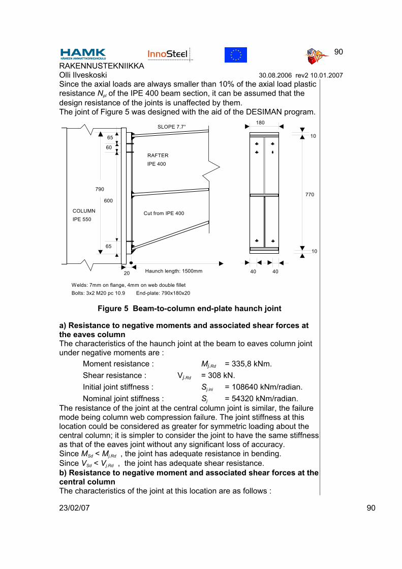
RAKENNUSTEKNIIKKA Olli Ilveskoski 30.08.2006 rev2 10.01.2007
23/02/07 90
90
Since the axial loads are always smaller than 10% of the axial load plastic resistance Npl of the IPE 400 beam section, it can be assumed that the design resistance of the joints is unaffected by them. The joint of Figure 5 was designed with the aid of the DESIMAN program.
10
770
10
40 40
180
IPE 400
Welds: 7mm on flange, 4mm on web double filletBolts: 3x2 M20 pc 10.9 End-plate: 790x180x20
790
65
65
600
60
SLOPE 7.7°
Haunch length: 1500mm20
Cut from IPE 400IPE 550COLUMN
RAFTER
Figure 5 Beam-to-column end-plate haunch joint
a) Resistance to negative moments and associated shear forces at the eaves column The characteristics of the haunch joint at the beam to eaves column joint under negative moments are : Moment resistance : Mj.Rd = 335,8 kNm. Shear resistance : Vj.Rd = 308 kN. Initial joint stiffness : Sj.ini = 108640 kNm/radian. Nominal joint stiffness : Sj = 54320 kNm/radian. The resistance of the joint at the central column joint is similar, the failure mode being column web compression failure. The joint stiffness at this location could be considered as greater for symmetric loading about the central column; it is simpler to consider the joint to have the same stiffness as that of the eaves joint without any significant loss of accuracy. Since MSd < Mj.Rd , the joint has adequate resistance in bending. Since VSd < Vj.Rd , the joint has adequate shear resistance. b) Resistance to negative moment and associated shear forces at the central column The characteristics of the joint at this location are as follows :
RAKENNUSTEKNIIKKA Olli Ilveskoski 30.08.2006 rev2 10.01.2007
23/02/07 91
91
Moment resistance: Mj.Rd = 360 kNm. Shear resistance: Vj.Rd = 308 kN. Initial joint stiffness: Sj.ini = 150537 kN.m/radian. Nominal Rigidity: Sj = 75268 kN.m/radian. Since MSd < Mj.Rd , the joint has adequate resistance in bending. Since VSd < Vj.Rd , the joint has adequate shear resistance. c) Joint classification This joint can be classified as rigid since :
25532049108640
bEIbLini,jS
>==
and 255,732049150537
bEIbLini,jS
>==
Since for negative moments 0.103,18,3268,335
plMRd.jM
>== , the joint is a full-
strength joint. Conclusions
An analysis of the structure accounting for the semi-rigid characteristics of the beam-to-column joints was also been carried out. It shows only a slight reduction in the moments at the beam-to-column joints with a corresponding slight increase in the mid-span moments. The small change in the moments obtained reflects the fact that the joints are quite rigid despite the absence of lateral stiffeners in the columns. If horizontal web stiffeners were used, a smaller central column could be adopted and the eaves columns could be reduced to an IPE 500. However IPE 450 rafters are needed to avoid excessive loading in the column. As a result, this solution is not necessarily more economical in steel weight than the IPE 550 column/IPE 400 rafter solution; in addition it involves extra fabrication costs due to the use of column web stiffeners. The other commonly used strategy for obtaining global economy is to use plastic design, but designs so obtained will usually require the more costly stiffened joints and, probably, a greater design effort. Which approach leads to the most economical solution can be determined only by the fabricator and/or designer. It was decided to omit shear and horizontal web stiffeners in the column so as to provide the potential of economy in fabrication and in erection by simplification of the joint detailing. The possibility that the joints can be semi-rigid is therefore permitted, a priori. However it is demonstrated that by a judicious choice of members of sufficient strength and rigidity, the joints can be considered as rigid. The central column member size has been dictated in part by the absence of column web stiffeners, but the rafter and the eaves columns have not been affected by this option in joint detailing.

RAKENNUSTEKNIIKKA Olli Ilveskoski 30.08.2006 rev2 10.01.2007
23/02/07 92
92
.