Structural Special Report Steelwork - Steel Construction
11
Structural Steelwork in Action Showcasing innovative uses of steel, from transport to commercial structures, plus the latest on environmental impact analysis New Civil Engineer in association with BCSA and Tata Steel Special Report 27|11|14 >> Contents | p02 London Bridge Station | p04 River Taff Central Link Bridge | p06 Embodied carbon | p08 St James’s Market | p10 St Vincent Plaza
Transcript of Structural Special Report Steelwork - Steel Construction

Structural Steelwork in Action
Showcasing innovative uses of steel, from transport to commercial structures, plus the latest on environmental impact analysis
New Civil Engineer in association with BCSA and Tata Steel
Special Report27|11|14 >>
Contents | p02 London Bridge Station | p04 River Taff Central Link Bridge | p06 Embodied carbon | p08 St James’s Market | p10 St Vincent Plaza
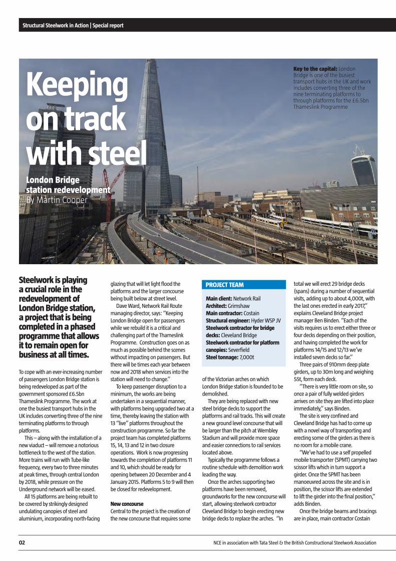
Steelwork is playing a crucial role in the redevelopment of London Bridge station, a project that is being completed in a phased programme that allows it to remain open for business at all times.
To cope with an ever-increasing number of passengers London Bridge station is being redeveloped as part of the government sponsored £6.5bn Thameslink Programme. The work at one the busiest transport hubs in the UK includes converting three of the nine terminating platforms to through platforms.
This – along with the installation of a new viaduct – will remove a notorious bottleneck to the west of the station. More trains will run with Tube-like frequency, every two to three minutes at peak times, through central London by 2018, while pressure on the Underground network will be eased.
All 15 platforms are being rebuilt to be covered by strikingly designed undulating canopies of steel and aluminium, incorporating north-facing
glazing that will let light flood the platforms and the larger concourse being built below at street level.
Dave Ward, Network Rail Route managing director, says: “Keeping London Bridge open for passengers while we rebuild it is a critical and challenging part of the Thameslink Programme. Construction goes on as much as possible behind the scenes without impacting on passengers. But there will be times each year between now and 2018 when services into the station will need to change.”
To keep passenger disruption to a minimum, the works are being undertaken in a sequential manner, with platforms being upgraded two at a time, thereby leaving the station with 13 “live” platforms throughout the construction programme. So far the project team has completed platforms 15, 14, 13 and 12 in two closure operations. Work is now progressing towards the completion of platforms 11 and 10, which should be ready for opening between 20 December and 4 January 2015. Platforms 5 to 9 will then be closed for redevelopment.
New concourseCentral to the project is the creation of the new concourse that requires some
of the Victorian arches on which London Bridge station is founded to be demolished.
They are being replaced with new steel bridge decks to support the platforms and rail tracks. This will create a new ground level concourse that will be larger than the pitch at Wembley Stadium and will provide more space and easier connections to rail services located above.
Typically the programme follows a routine schedule with demolition work leading the way.
Once the arches supporting two platforms have been removed, groundworks for the new concourse will start, allowing steelwork contractor Cleveland Bridge to begin erecting new bridge decks to replace the arches. “In
total we will erect 29 bridge decks (spans) during a number of sequential visits, adding up to about 4,000t, with the last ones erected in early 2017,” explains Cleveland Bridge project manager Ben Binden. “Each of the visits requires us to erect either three or four decks depending on their position, and having completed the work for platforms 14/15 and 12/13 we’ve installed seven decks so far.”
Three pairs of 910mm deep plate girders, up to 30m long and weighing 55t, form each deck.
“There is very little room on site, so once a pair of fully welded girders arrives on site they are lifted into place immediately,” says Binden.
The site is very confined and Cleveland Bridge has had to come up with a novel way of transporting and erecting some of the girders as there is no room for a mobile crane.
“We’ve had to use a self propelled mobile transporter (SPMT) carrying two scissor lifts which in turn support a girder. Once the SPMT has been manoeuvred across the site and is in position, the scissor lifts are extended to lift the girder into the final position,” adds Binden.
Once the bridge beams and bracings are in place, main contractor Costain
Structural Steelwork in Action | Special report 11 | 2014
02 NCE in association with Tata Steel & the British Constructional Steelwork Association
Main client: Network RailArchitect: GrimshawMain contractor: CostainStructural engineer: Hyder WSP JVSteelwork contractor for bridge decks: Cleveland BridgeSteelwork contractor for platform canopies: SeverfieldSteel tonnage: 7,000t
PROJECT TEAM
Keeping on track with steelLondon Bridge station redevelopmentBy Martin Cooper
Key to the capital: London Bridge is one of the busiest transport hubs in the UK and work includes converting three of the nine terminating platforms to through platforms for the £6.5bn Thameslink Programme

casts the decks, encasing the beams but leaving the bottom flange exposed.
The decks then form the slab supporting the new tracks and precast platform units, while the bottom flange, which is weathering steel, is covered with cedar cladding as part of the concourse roof.
“Weathering steel was chosen for the bottom flanges because it won’t need to be painted in the future,” explains Hyder WSP structural lead Peter Anstock. “This cuts down on maintenance work and the future need to close areas of the concourse for repainting works.”
Steel is also playing a leading role on
top of the bridge decks where Severfield is delivering a further 3,000t of steelwork. “Our steel erection programme begins with a connection to Cleveland’s bridge decks,” explains Severfield contracts manager Nick Scott. “This steel, that we call the
‘elephant’s ears’, supports a steel plinth that acts as a mounting for the precast platform units and the canopy columns.”
Once the precast platform units have been installed, which is also part of Severfield’s remit, the company then has to erect a series of 3.8m high Y-shaped columns spaced at 15m centres. The columns are connected via spine beams that help support a series of prefabricated steel cassettes (see box). These in turn form the station’s curving canopy as well as accommodat-ing services.
To ensure the erection programme
ran as smoothly as possible, Severfield undertook a trial assembly of a 54m long canopy prior to starting work on site.
“Future maintenance of the canopy could have been an issue for the client. The trial assured Network Rail that they could easily gain access to the services once the project was completed,” adds Hyder WSP senior technical director John Parker.
The redevelopment of London Bridge station will complete the wider London Bridge Quarter scheme, a high profile project that also includes The Shard, The Place and a new bus station.
Structural Steelwork in Action | Special report 11 | 2014
NCE in association with Tata Steel & the British Constructional Steelwork Association 03
In total 1,200 prefabricated steel roof cassettes will be installed by Severfield, with each one a bespoke unit due to the changing high level geometry.
They are 9m deep by 3m wide and fabricated from galvanized I-section rafters. Once they have been assembled at Severfield’s Bolton factory, the project’s M&E contractor installs the services and the cladding contractor, using Kalzip roofing, forms
the cassette’s individual canopy roof. The completed cassettes are then
delivered to site in loads of up to three units per truck, and because they only weigh 2.5t each they are lifted into place by one of the site’s tower cranes.
Severfield is producing about 10 of these units every week and Network Rail estimates that the prefabricated cassettes are taking weeks off of the programme, as less on-site work is required.
PREFABRICATED CASSETTES
Room to move: The new station concourse will be larger than the pitch at Wembley Stadium
Ingenious: Cleveland Bridge has developed a special method of erecting girders
“There is very little room on site, so once a pair of fully welded girders arrive on site they are lifted into place immediately” Ben Binden, Cleveland Bridge

A steel composite bridge forms the main element of a multi-million pound regeneration scheme in Merthyr Tydfil.
The River Taff Central Link Bridge forms an important element of Merthyr Tydfil’s £24M regeneration programme.
Funded by the European Regional Development Fund and the Welsh Government, the regeneration masterplan encompasses a number of town centre enhancements, with the new road bridge helping to make the riverside area an attractive destination for future investment.
A number of design options went out to consultation with the local planning and highways authorities, together with other stakeholders, and the favoured design was for a bridge with an iconic arch.
Locally based civil engineering company Alun Griffiths was chosen as the principal contractor for the project, while Mabey Bridge was awarded the bridge construction subcontract package.
Designed by Capita, the bridge’s stand out feature is a 136t skewed arch. Measuring 40.9m across its base and reaching a maximum height of 18.5m, it was fabricated from 60mm thick plate. Connecting the
arch to the bridge deck are a total of 14, 80mm diameter hangers ranging in length from 4.7m to 22.5m.
One of the project’s main technical challenges revolved around the hangers and the associated cable tensioning.
“During the non-linear analysis of the installation and stressing procedure for the hangers, we found that some hangers would go into compression if the full pre-stress design was induced in an adjacent hanger,” says Capita project engineer Christopher Prosser.
“We therefore had to design an incremental tensioning sequence to prevent this occurring. The designed sequence was later streamlined by Mabey Bridge during the construction phase in order to speed up the process.”
The appearance of the bridge was critical to the overall design and so it was decided that each hanger fin plate would be designed with the same geometry, but with varying orientation to suit the alignment of the hangers. This required Capita to extensively model each element to ensure there were no clashes and
Structural Steelwork in Action | Special report 11 | 2014
04 NCE in association with Tata Steel & the British Constructional Steelwork Association
A bridge to South Wales renewalThe River Taff Central Link BridgeBy Martin Cooper
One of the project’s main technical challenges revolved around the hangers and the associated cable tensioning

determine the practicalities of completing the internal welds, while ensuring the alignment of the hangers between the top and bottom plates was correct both aesthetically and structurally.
When designing the structure, it was also necessary to take into account the BS EN 1993-1-11 requirement for the loss of a hanger without any restriction to live load capacity.
“This required us to model what effect the loss of a hanger had on the remaining structural elements for the critical loading case. This analysis resulted in the increasing of the diameter of the hangers and associated fixings,” says Prosser.
For the site erection programme, the 29m long, 19.8m wide deck was the first steelwork to be installed earlier this year by Mabey Bridge. It is formed with a ladder configuration with two main 900mm deep, 600m wide outer girders, each 29m long, connected by a series of nine crossbeams.
“We erected the deck steelwork using MEWPs positioned on each riverbank in conjunction with one 250t capacity crane,” says Mabey Bridge project manager Andy Hosking. “Once the beams were
erected we then bolted on the cantilevers which support the parapets as well as having the deck connection for the hangers.”
Mabey Bridge’s contract required it to have input in a number of aspects relating to the project, not just the steelwork detailing, but also construction methodology, and cable installation and stressing. However, the company’s main recommenda-tion was to fully assemble the arch and then lift the complete structure into position.
This eliminated working at height as well as having environmental benefits, as no trestles were installed into the fast flowing river.
Working in this way also reduced the construction programme, as steelwork fabrication was carried out off site by Mabey Bridge while Alun
Griffiths was constructing the substructure on site
The arch was transported to site in four equal sections from Mabey Bridge’s Newhouse manufacturing facility which is 88km from Merthyr Tydfil.
Once on site, the sections were placed on temporary trestles and welded together to produce the continuous and completed arch.
Using a single 550t capacity mobile crane positioned on one of the riverbanks, the entire arch was lifted into a vertical position and slewed over the river to its final position where it was fixed to the abutments.
“The entire lifting procedure took eight hours and a large crowd, including school children and council representatives, gathered to watch,” says Hosking.
Commenting on the bridge, which is scheduled to open in November, Merthyr Tydfil County Borough Council project manager Daniel Francis says: “It is an iconic structure that also opens up areas of the town for future development.
“It is also a key structure in our redevelopment programme that will, along with a new road system, cater for our anticipated increase in visitors to the town.”
Structural Steelwork in Action | Special report 11 | 2014
NCE in association with Tata Steel & the British Constructional Steelwork Association 05
PROJECT TEAMMain client: Merthyr Tydfil County Borough CouncilPrincipal contractor: Alun Griffiths (Contractors)Structural engineer: Capita Steelwork contractor: Mabey BridgeSteel tonnage: 280t
“The entire lifting procedure took eight hours and a large crowd, including school children and council representatives, gathered to watch” Andy Hosking, Mabey Bridge
Angle of attack: The bridge’s stand out feature is a 136t skewed arch

As efforts to reduce operational carbon in buildings through improved legislation and standards start to have an effect the relative importance of embodied carbon is increasing.
The Government has set ambitious and legally binding targets to reduce national greenhouse gas emissions and as the operation of buildings currently accounts for nearly half of these a significant improvement in new and existing building performance is required if these targets are to be met.
This is being achieved for new buildings by enhancing the standards set out in Approved Document L.
But what is embodied carbon? The term embodied carbon, when applied to construction materials or products, refers to the lifecycle greenhouse gas emissions that occur during their manufacture. The definition can also include any emissions that occur during the construction process, the operational lifetime of the building and the end of life disposal of the materials used in the building.
This is sometimes referred to as the cradle to (factory) gate option, the cradle to (installation) site option, or the cradle-to-cradle option, the latter of which is also known often as the whole life approach. “The steel industry promotes the whole life approach to embodied carbon calculation,” says
John Dowling, British Constructional Steelwork Association sustainability manager. “Only this cradle to cradle method will give you an holistic understanding of the lifetime impacts of construction materials. The other methods fail to do this.”
Dowling goes on to say: “The strength of a cradle to gate approach to embodied carbon calculation has in the past been that information has been readily available for most materials. The quality of that data may be question-able on occasion but its saving grace is that it has been there.
“The weaknesses however are significant because the cradle to gate approach assumes that all materials are more or less equal at end of life. So, recycling is deemed to be the same as landfill and a material that leaves a detrimental legacy when it comes to the end of its useful life is considered to be the same as one that leaves a positive impact.
“The strength of a cradle-to-cradle approach is that it does not assume that all end of life outcomes are equal and that positive outcomes at end of life, such as recycling are rewarded and negative outcomes, such as landfill, are penalised. In the past, the weakness of this approach has been a lack of whole
Structural Steelwork in Action | Special report 11 | 2014
06 NCE in association with Tata Steel & the British Constructional Steelwork Association
In order to assist designers, robust data has been sourced for the extraction and manufacture lifecycle stages and combined with an end of life dataset developed by PE International, a leading provider of sustainable solutions.
The result is a robust and compre-hensive dataset of embodied carbon impacts for materials commonly
used in construction. Data for all the materials can be viewed along with sources for the cradle to gate data used.
Designers using this dataset can have confidence in its transparency, robustness and consistency, enabling comparison between different frame options to be accurately and effectively carried out on any project.
EMBODIED CARBON DATA
Importance of carbon calculationEmbodied carbonBy John Dowling, BCSA
“The steel industry promotes the whole life approach to embodied carbon calculation” John Dowling, BCSA
Manufacture
Extraction
EmbodiedCarbon
Lifecycle
Transport
ConstructionDemolition
Recycling
One Kingdom Street London: Tests showed that less carbon was produced as a result of the decision to use a steel frame

life data, but that has now been remedied. The steel, concrete and timber industries have all put their houses in order and produced good, reliable end of life data. ”
To help the construction industry navigate its way through the process of embodied carbon calculation, Tata Steel and the British Constructional Steelwork Association have published a
guide on the subject, the latest in their series of steel construction guidance publications.
A must read for the entire construc-tion industry, the guide explains what embodied carbon is and how it impacts on the total emissions of a building throughout its lifecycle. The guide gives designers an overview of how embodied carbon should be considered
and calculated, some practical guidance on how to assess it on individual projects, and the significance of end of life impacts, while some case studies show how structural steelwork compares with other framing materials.
n The guide is available for download at www.steelconstruction.info/Steel_construction_news
Structural Steelwork in Action | Special report 11 | 2014
NCE in association with Tata Steel & the British Constructional Steelwork Association 07
A web tool that enables designers of multi-storey buildings to easily estimate the embodied carbon footprint of the superstructure has been developed and is available for download at www.steelconstruc-tion.info/Design_software_and_tools.
Designers can use the tool in two ways. In ‘auto-generate’ mode, the basic building geometry, structural grid and chosen floor system are used to estimate structural material quantities using algorithms developed by the Steel Construction Institute (SCI).
Alternatively, a user may use the ‘manual input’ mode to enter the actual material quantities for the building. To compare the impact of a steel framed building with a concrete framed building; the web tool should be run separately for each building.
EMBODIED CARBON DATA
HELP FOR DESIGNERS
Product
BS EN 15804 ModulesTotal
(kgCO2 e/kg)A1-A3
(kgCO2 e/kg)
C1-C4(kgCO
2 e/kg)
D(kgCO
2 e/kg)
Brickwork 0.16 0.01 -0.0207 0.15
Concrete blockwork 0.09 0.0103 -0.0053 0.10
C40 concrete 0.13 0.0043 -0.0053 0.13
C50 concrete 0.17 0.0037 -0.0053 0.17
Lightweight C40 concrete 0.17 0.0111 -0.0053 0.18
Hollowcore slab 0.2 0.0006 -0.0103 0.19
Hot rolled plate and structural sections 1.735 0.06 -0.959 0.84
Hot formed structural hollow sections 2.49 0.06 -1.38 1.17
Reinforcing steel 1.27 0.061 -0.426 0.91
Steel deck 2.52 0.06 -1.45 1.13

A major investment programme to revitalise the St James’s area of central London with a new public square, offices, retail outlets and high quality residences is underway.
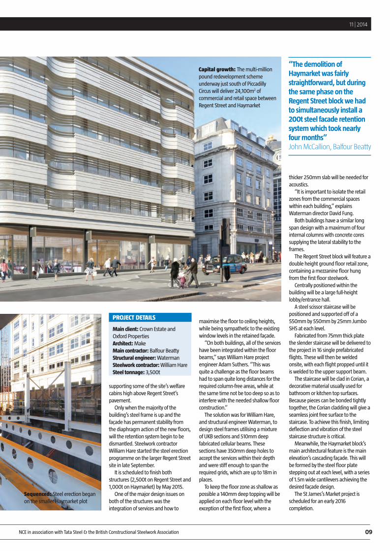
The flagship of the multi-million pound redevelopment scheme underway just south of Piccadilly Circus and once the site of a West End market, will deliver 24,100m2 of commercial and retail space between two of London’s most prestigious thoroughfares, Regent Street and Haymarket.
Known as the St James’s Market project, it features two adjacent steel-framed, eight-storey buildings. One at 14-22 Regent Street will feature a retained façade, allowing the new structure to fit seamlessly into its historic streetscape. Behind the façade, a new steel framed structure will be erected accommodating retail at basement and ground floor levels, with offices above.
The 52-56 Haymarket block has a slightly smaller footprint, but will be highlighted by curved cladding incorporating glass, Portland stone and horizontal metal detailing in keeping with the surroundings. Like its neighbour, this steel framed structure will also have retail space at basement and ground floor levels, with offices occupying the upper seven floors.
Working on behalf of Crown Estate
and Oxford Properties, main contractor Balfour Beatty started on site in September 2013. The demolition phase commenced almost immediately, with the entire Haymarket plot cleared and the adjoining Regent Street block demolished with the exception of the 140m-long retained 1920s façade that runs along most of three elevations.
Early works have also included excavating and deepening the Regent Street block’s basement and making provision for its service ramp. As the Haymarket structure’s basement lacks the space for a ramp, a 5.5m-long tunnel beneath St Albans Street will connect both buildings.
“The demolition of Haymarket was fairly straightforward, but during the same phase on the Regent Street block we had to simultaneously install a 200t steel façade retention system which took nearly four months,” says Balfour Beatty project director John McCallion.
Regent Street’s Grade II listed retained façade is predominantly 350mm deep and made of masonry wrapped around a supporting steel frame. To keep this five-storey high wall stable during the demolition and construction phase, engineers from Wentworth House Partnership designed a support frame consisting of a series of steel belt trusses and braced steel towers. The façade is clamped to the belt trusses with ties through the windows and internal waler beams, all carefully set out to avoid clashes with the new steelwork.
The belt trusses are substantial and serve a double purpose by also
Structural Steelwork in Action | Special report 11 | 2014
08 NCE in association with Tata Steel & the British Constructional Steelwork Association
Steel revives former West End market St James’s Market, LondonBy Martin Cooper
supporting some of the site’s welfare cabins high above Regent Street’s pavement.
Only when the majority of the building’s steel frame is up and the façade has permanent stability from the diaphragm action of the new floors, will the retention system begin to be dismantled. Steelwork contractor William Hare started the steel erection programme on the larger Regent Street site in late September.
It is scheduled to finish both structures (2,500t on Regent Street and 1,000t on Haymarket) by May 2015.
One of the major design issues on both of the structures was the integration of services and how to
maximise the floor to ceiling heights, while being sympathetic to the existing window levels in the retained façade.
“On both buildings, all of the services have been integrated within the floor beams,” says William Hare project engineer Adam Suthers. “This was quite a challenge as the floor beams had to span quite long distances for the required column-free areas, while at the same time not be too deep so as to interfere with the needed shallow floor construction.”
The solution was for William Hare, and structural engineer Waterman, to design steel frames utilising a mixture of UKB sections and 510mm deep fabricated cellular beams. These sections have 350mm deep holes to accept the services within their depth and were stiff enough to span the required grids, which are up to 18m in places.
To keep the floor zone as shallow as possible a 140mm deep topping will be applied on each floor level with the exception of the first floor, where a
thicker 250mm slab will be needed for acoustics.
“It is important to isolate the retail zones from the commercial spaces within each building,” explains Waterman director David Fung.
Both buildings have a similar long span design with a maximum of four internal columns with concrete cores supplying the lateral stability to the frames.
The Regent Street block will feature a double height ground floor retail zone, containing a mezzanine floor hung from the first floor steelwork.
Centrally positioned within the building will be a large full-height lobby/entrance hall.
A steel scissor staircase will be positioned and supported off of a 550mm by 550mm by 25mm Jumbo SHS at each level.
Fabricated from 75mm thick plate the slender staircase will be delivered to the project in 16 single prefabricated flights. These will then be welded onsite, with each flight propped until it is welded to the upper support beam.
The staircase will be clad in Corian, a decorative material usually used for bathroom or kitchen top surfaces. Because pieces can be bonded tightly together, the Corian cladding will give a seamless joint free surface to the staircase. To achieve this finish, limiting deflection and vibration of the steel staircase structure is critical.
Meanwhile, the Haymarket block’s main architectural feature is the main elevation’s cascading façade. This will be formed by the steel floor plate stepping out at each level, with a series of 1.5m wide cantilevers achieving the desired façade design.
The St James’s Market project is scheduled for an early 2016 completion.
Structural Steelwork in Action | Special report 11 | 2014
NCE in association with Tata Steel & the British Constructional Steelwork Association 09
Main client: Crown Estate and Oxford PropertiesArchitect: MakeMain contractor: Balfour BeattyStructural engineer: WatermanSteelwork contractor: William HareSteel tonnage: 3,500t
PROJECT DETAILS
Capital growth: The multi-million pound redevelopment scheme underway just south of Piccadilly Circus will deliver 24,100m2 of commercial and retail space between Regent Street and Haymarket
“The demolition of Haymarket was fairly straightforward, but during the same phase on the Regent Street block we had to simultaneously install a 200t steel facade retention system which took nearly four months” John McCallion, Balfour Beatty
Sequenced: Steel erection began on the smaller Haymarket plot

A Breeam “Excellent” flexible office block has made use of structural steelwork to complete its architectural vision in quick time.
A number of high profile commercial schemes are currently underway in Scotland’s largest city including St Vincent Plaza, a striking and efficient building that will provide 15,700m2 of Grade A office space spread over 11 floors.
Located in the city’s business district, St Vincent Plaza will feature a prestigious double height reception area and all of the 10 upper floors will benefit from large flexible column free spaces, due to the structural steel frame only having four internal columns.
The project’s flexibility and future proofing has been further enhanced with the addition of enlarged riser space that will allow tenants to add additional cabling and ducting.
Main contractor Bowmer & Kirkland started work onsite during October 2013 on a plot that was formerly a car park for an adjacent bank. The company’s work com-menced with the construction of a nearby replacement car park for the bank’s employees. Once this was complete enabling and piling work could begin on the site.
A series of 25m deep piles support a split-level stepped suspended slab that takes into account the sloping site. Consequently the southern elevation includes a lower ground level, while at the northern side
(main entrance level) the lowest level is ground floor.
The building’s steel frame springs off of pile caps and is set out on a regular 9m by 11m grid. Fabricated cellular beams, with service holes, have been used on every floor for easy M&E integration.
According to the construction team, all framing options for this project were evaluated during the early stages of the design process.
“This is a speculative office development and getting the completed building onto the market as quickly as possible was very important to the client. So a fast track construction programme was essential and steel was the best option for this,” says Keppie Design architect Richard MacDonald.
The steel framed building was then designed around a number of site constraints, namely the adjacent M8 motorway and its connecting flyover, and a 22m no build zone separating the site from its next door neighbour.
The proximity of the M8 meant a number of rock anchors, installed during the motorway’s construction protruded into the St Vincent Plaza site. This meant some of the structure’s piles and columns had to be designed and installed so as not to clash with these. As the site is
bounded by roads along three sides, laydown areas for materials are at a premium in and around the project. Steelwork was generally brought to site and erected immediately, leaving other areas of the site clear for other trades to work in. If the project team had gone down a different framing route, the site may have been much more congested with plant and materials, making the logistics far more testing.
“When the steel erection programme initially started, we were still piling one part of the site, so coordination between trades has always been a key challenge on this job,” explains Bowmer & Kirkland
senior project manager Paul Wilson. The structure’s steel frame gains all
of its stability from diagonal bracing, most of which is located within the building’s centrally located core. However, some bracing was needed in other locations to afford additional stiffness and this proved to be a challenge.
Struer director Eddie Gray says: “Where to put the extra bracing was difficult, as there are no internal partitions to use and we obviously had to avoid window openings and so any blank panels on the exterior at the lower levels generally conceal diagonal bracing.”
More bracing is also located within
Structural Steelwork in Action | Special report 11 | 2014
10 NCE in association with Tata Steel & the British Constructional Steelwork Association
City centre landmarkSt Vincent Plaza, GlasgowBy Nick Barrett
“Coordination between trades has always been a key challenge on this job” Paul Wilson, Bowmer & Kirkland

the building’s most visual elements, two cantilevers positioned on the north and south elevations. Both are one bay wide (9m), with the southern element cantilevering by 4.5m and the northern by 6m.
“As well as breaking up the main facades, the north cantilever projects presence along St Vincent while the south cantilever addresses the views into the city centre from the M8,” explains MacDonald.
In order to accommodate a 1.5m step-in at ground and first floor levels a girder and truss arrangement was provided over the second and third floors to support the seven floors above and the 6m cantilever. The
structural arrangement incorporated two 21m long plate girders each weighing 14t.
From the fourth level upwards, more traditional rolled sections are used for the cantilever. To minimise deflection of the 6m cantilever
structure, diagonal struts were installed to provide stiffness.
Steelwork contractor BHC had to bring in a 100t capacity mobile crane to lift in the cantilevering girders, with the rest of the steel frame being mostly erected via the site’s tower crane.
Its contract also included the installation of metal decking and precast stairs, as well as erecting 60t of cold rolled steelwork for the rooftop plant enclosures.
Steelwork erection, which involved more than 3,300 individual pieces, was finished last June, and the overall project is scheduled to be completed by mid-2015.
Structural Steelwork in Action | Special report 11 | 2014
NCE in association with Tata Steel & the British Constructional Steelwork Association 11
PROJECT DETAILSClient: AbstractArchitect: Keppie DesignMain contractor: Bowmer & KirklandStructural engineer: StruerSteelwork contractor: BHCSteel tonnage: 1,800t
The structure’s steel frame gains all of its stability from diagonal bracing, most of which is located within the building’s centrally located core
Angle of attack: The bridge’s stand out feature is a 136t skewed arch
Prime location: The new St Vincent Plaza building will provide 15,700m2 of Grade A office space spread over 11 floors
Feature elements: One of the structure’s two cantilevers

![Cost of Structural Steelwork[1]](https://static.fdocuments.net/doc/165x107/577cdcd01a28ab9e78ab7677/cost-of-structural-steelwork1.jpg)