STRUCTURAL PROBLEMS IN THE DESIGN OF … · 1488 STRUCTURAL PROBLEMS IN THE DESIGN OF LARGE MASONRY...
8
1488 STRUCTURAL PROBLEMS IN THE DESIGN OF LARGE MASONRY HALLS PROF . K.-J. SCHNEIDER Fachhochschule Bielefeld I Abteilung Minden ArtilleriestraBe 9, D-4950 Minden, Germany ABSTRACT lhe paper deals with some structural problems arlslng with the construc of a covered market having the dimensions 50 x 20 m and a height of 4,5 Four structural variations are analysed. Structural stability, stresses in bending and shear, as well as reinforced masonry as an alternative structural solution are outlined . INTRODUCTlON Using a covered market as an example the structural problems of large masonry halls are outlined. lhe roof of the hall consists of a timber truss with a gradient of 30 0 C (cf. figo 1). For aesthetical, physical and technical reasons only masonry materials are to be used. Four struc ral variations in terms of lateral load resistance are looked at: 1. Horizontal diaphragm being confined by vertical diaphragms at ends . 2. Masonry pilasters at 6,25 m centers. 3. Reinforced concrete columns fixed into single foundations which are covered by masonry of 115 mm thickness. 4. Fixed reinforced masonry columns. lhe masonry walls are topped with a r.c . or r.m . ring beam. lhey are calculated as slabs under wind load restrained by the vertical stif ning elements and the horizontal supports (ground floor slab, ring beam above). Load is taken biaxially. Depending on the local conditions expans joints at 15 to 25 m centers should be provided. In addition to the stability the following is looked at more elos (a) stresses at gaping cracks for sections other than rectangular (l-se tions, cross-sections)
Transcript of STRUCTURAL PROBLEMS IN THE DESIGN OF … · 1488 STRUCTURAL PROBLEMS IN THE DESIGN OF LARGE MASONRY...

1488
STRUCTURAL PROBLEMS IN THE DESIGN OF LARGE MASONRY HALLS
PROF . K.-J. SCHNEIDER Fachhochschule Bielefeld I Abteilung Minden ArtilleriestraBe 9, D-4950 Minden, Germany
ABSTRACT
lhe paper deals with some structural problems arlslng with the construc of a covered market having the dimensions 50 x 20 m and a height of 4,5 Four structural variations are analysed. Structural stability, stresses in bending and shear, as well as reinforced masonry as an alternative structural solution are outlined .
INTRODUCTlON
Using a covered market as an example the structural problems of large masonry halls are outlined. lhe roof of the hall consists of a timber truss with a gradient of 300C (cf. figo 1). For aesthetical, physical and technical reasons only masonry materials are to be used. Four struc ral variations in terms of lateral load resistance are looked at:
1. Horizontal diaphragm being confined by vertical diaphragms at ends .
2. Masonry pilasters at 6,25 m centers.
3. Reinforced concrete columns fixed into single foundations which are covered by masonry of 115 mm thickness.
4. Fixed reinforced masonry columns.
lhe masonry walls are topped with a r.c . or r.m . ring beam. lhey are calculated as slabs under wind load restrained by the vertical stif ning elements and the horizontal supports (ground floor slab, ring beam above).
Load is taken biaxially. Depending on the local conditions expans joints at 15 to 25 m centers should be provided.
In addition to the stability the following is looked at more elos
(a) stresses at gaping cracks for sections other than rectangular (l-se tions, cross-sections)

1489
49 .99
19.99 ,
Figure 1
60,w. l
o ao

1490
(b) shear stresses in combined sections
(c) r .m. beams and columms.
STRUCTURAL STABILITY For large masonry halls the most severe problem is the structural stability. In principle, these are two possibilities to transfer wind loads to the foundation:
(a) Horizontal diaphragm on top of the wall: Out-of-plan wind loads are taken by the wal1s as vertlca1 slmp1e spanned beams and transferned to bottom (bottom slab) and on top of the diaphragms. Vertical load from the roof and the wall shall be sufficient to allow for a gaping crack width of half of the wall thickness at most o The upper horizontal diaphragm is supported on vertical masonry diaphragms which transfer the wind load into the foundation.
(b) No horizontal diaphragm on top of the wall : In this case out-of-plan wlnd loads cause slab action of the wa11 and are transferred directly into the stiffening elements (pilasters, fixed columns), and further to the foundations .
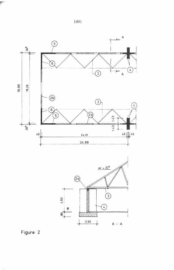
Halls with horizontal diaphragms at roof level (fig . 2)
The roof construction is a timber truss . In the plane of the bottom chord four horizontal truss diaphragms with 25 m in length are provided parallely to the longitudinal walls (Pos. 3 in figo 2). Wind loades (perpend to the longitudinal walls) are transferred to the knots of the horizontal truss diaphragms through the U-shaped r.C. ring beams (Pos. 2a) .
The horizontal truss diaphragms are supported on top of the masonry pilasters (Pos . 4 and 6) . Wind loads perpend to the gable walls are transferred by a 20 m span ring beam directly to two vertical wall diaphragms (P os. 5).
For the stiffening parts of the wall (Pos. 4 to 6) the following was verified:
(a) structural stability (safety factor 1,5)
(b) safety against failure (vertical loads, wind, deviation from the verti cal)
(c) shear strength (un it failure, mortar joint failure, edge strain) .
Halls without horizontal diaphragms at roof level
Stiffening by pilasters (fig . 3) : All masonry walls are topped with a r .m. ring beam (Pos. 10) . Each wall segment is two-way spanned between the horizontal supports (ring beam and ground slab) and the vertical supports (pilasters, Poso 11) . In the horizontal divection a certain tensile strength for the masonry was adopted. Vertically, gaping cracks were assumed .
cn cn ~.
ID N
~
'" ID
""
Figure 2
®
o li> ~.
o ao
1491
24,01
24. 99
l 3,50 , l 1
~A
I
A - A

l l
1 on 1
@
@
v - v
66'72:
V
~ @
~V
Z6vT
O> o
.... <.n o
@
w '" '" ~
.'" w '"
-=~
.'" lO ~ io
lO
~
.'" w '"
-
w
'" '"

1493
The pilasters (Pos. 11) were calculated i analogy to the previous chapter. The calculation is relatively complicated because in a first step the neutral axis of the circle section must be determined iteratively (e .g. according to /1/). Then ultimate state design is carried out for the edge. For the shear design only the area subjected to compression may be taken into account. The ring beam is designed with the well-known kh-method (cf. /4/).
The structural design presented herein will not be of great practical importance in this form because erecting the pilasters will be relatively expensive. However, this variation of construction might gain some importance in case of a roof with lower gradient or a flat roof. In this cases the smaller wind loads would permit the dimensions of the pilasters to be considerably smaller.
Stiffening by reinforced concrete columns (fig. 4): An economical alternatlve to masonry pllasters are flxed r.C. columns. The columns are coated by masonry formwork units. The formwork units are connected to the adjacent masonry with structural reinforcement (fig. 4).
Stiffening with reinforced masonry columns (fig. 5): The columns fixed into the foundatlon are made of formwork unlts havlng cavities for the vertical reinforcement (fig. 5). Compared to r.c. columns this structural variation has advantages in terms of heat conductivity . The total outer area of the hall consists of masonry so that there is no thermal bridge .
All walls have a uniform aesthetical pattern.
REFERENCES 1. Schweda, E., Baustatik-Festigkeitslehre, Werner-Verlag, Düsseldorf,
2. Auflage 1987
2. Pohl, R., Schneider, K.-J. and Wormuth, R., Mauerwerksbau, WernerVerlag Düsseldorf, 2. Auflage 1987

~I UODOOI IODLJOu} c=::r:=JDDDoc=:JC DDDODI ID[JDDD~ ilc::r::J9 "tjDc:=J ~DÇJDDD ODDDDO - - ~- - _..Jl _ _ , - ----4.
3
Figure 4
CD (3)
o ({)
®
HL z 12/1.2 (acc. to DIN - Code)
column reinforcement
stirrup
shaped bricks
reinforcement of ring beam. galvanized
......
.j>. \O .j>.

[!J
[!] I
l·t I ayer
LI [!] 1Il!:1
00 11
2nd layer
Figure 5
11 II'Z;
CD o o o
HLz 12/1.2 lace. to OtN - Code)
shaped brieks
eolumn reinforeement
reinforeement of ring beam galvanized
...... ~ \O Vl