
Structural integrity monitoring RR685
104
Executive Health and Safety Structural integrity monitoring Review and appraisal of current technologies for offshore applications Prepared by Atkins Limited for the Health and Safety Executive 2009 RR685 Research Report
Transcript of Structural integrity monitoring RR685
Executive Health and Safety
Structural integrity monitoringReview and appraisal of current technologies for offshore applications
Prepared by Atkins Limited for the Health and Safety Executive 2009
RR685 Research Report
Executive Health and Safety
Structural integrity monitoringReview and appraisal of current technologies for offshore applications
Philip May Gaspard Mendy Paul Tallett Atkins Limited Saddlers House Gutter Lane London EC2V 6BR
David Sanderson (MMI)
John Sharp (Independent Consultant)
With the ageing of the North Sea fleet of platforms and semi-submersibles, the importance of maintaining structural integrity offshore is increasingly recognised and structural inspection plays a significant role in demonstrating ongoing integrity and the potential for life extension. Structural integrity (SI) monitoring can complement existing inspection techniques to provide greater confidence in structural integrity or to reduce inspection cost. It has been found that offshore experience of SI monitoring is limited to date and that current systems are for bespoke applications. This report focuses on fixed steel structures, topsides and semi-submersible hulls.
This report and the work it describes were funded by the Health and Safety Executive (HSE). Its contents, including any opinions and/or conclusions expressed, are those of the authors alone and do not necessarily reflect HSE policy.
HSE Books

© Crown copyright 2009
First published 2009
All rights reserved. No part of this publication may be reproduced, stored in a retrieval system, or transmitted in any form or by any means (electronic, mechanical, photocopying, recording or otherwise) without the prior written permission of the copyright owner.
Applications for reproduction should be made in writing to:Licensing Division, Her Majesty’s Stationery Office,St Clements House, 2-16 Colegate, Norwich NR3 1BQor by e-mail to [email protected]
ii
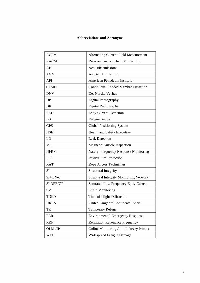
Abbreviations and Acronyms
ACFM Alternating Current Field Measurement
RACM Riser and anchor chain Monitoring
AE Acoustic emissions
AGM Air Gap Monitoring
API American Petroleum Institute
CFMD Continuous Flooded Member Detection
DNV Det Norske Veritas
DP Digital Photography
DR Digital Radiography
ECD Eddy Current Detection
FG Fatigue Gauge
GPS Global Positioning System
HSE Health and Safety Executive
LD Leak Detection
MPI Magnetic Particle Inspection
NFRM Natural Frequency Response Monitoring
PFP Passive Fire Protection
RAT Rope Access Technician
SI Structural Integrity
SIMoNet Structural Integrity Monitoring Network
SLOFECTM Saturated Low Frequency Eddy Current
SM Strain Monitoring
TOFD Time of Flight Diffraction
UKCS United Kingdom Continental Shelf
TR Temporary Refuge
EER Environmental Emergency Response
RRF Relaxation Resonance Frequency
OLM JIP Online Monitoring Joint Industry Project
WFD Widespread Fatigue Damage
iii

iv
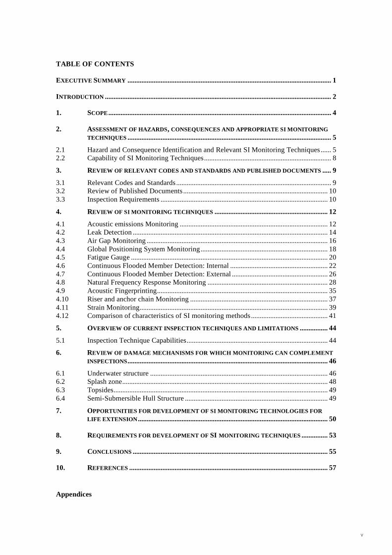
TABLE OF CONTENTS
EXECUTIVE SUMMARY ..................................................................................................................... 1
INTRODUCTION .................................................................................................................................. 2
1. SCOPE................................................................................................................................ 4
2. ASSESSMENT OF HAZARDS, CONSEQUENCES AND APPROPRIATE SI MONITORING
TECHNIQUES ..................................................................................................................... 5
2.1 Hazard and Consequence Identification and Relevant SI Monitoring Techniques ...... 52.2 Capability of SI Monitoring Techniques......................................................................... 8
3. REVIEW OF RELEVANT CODES AND STANDARDS AND PUBLISHED DOCUMENTS ..... 9
3.1 Relevant Codes and Standards ......................................................................................... 93.2 Review of Published Documents ................................................................................... 103.3 Inspection Requirements ................................................................................................ 10
4. REVIEW OF SI MONITORING TECHNIQUES ................................................................. 12
4.1 Acoustic emissions Monitoring ..................................................................................... 124.2 Leak Detection ................................................................................................................ 144.3 Air Gap Monitoring ........................................................................................................ 164.4 Global Positioning System Monitoring......................................................................... 184.5 Fatigue Gauge ................................................................................................................. 204.6 Continuous Flooded Member Detection: Internal ........................................................ 224.7 Continuous Flooded Member Detection: External ....................................................... 264.8 Natural Frequency Response Monitoring ..................................................................... 284.9 Acoustic Fingerprinting.................................................................................................. 354.10 Riser and anchor chain Monitoring ............................................................................... 374.11 Strain Monitoring............................................................................................................ 394.12 Comparison of characteristics of SI monitoring methods............................................ 41
5. OVERVIEW OF CURRENT INSPECTION TECHNIQUES AND LIMITATIONS ................ 44
5.1 Inspection Technique Capabilities................................................................................. 44
6. REVIEW OF DAMAGE MECHANISMS FOR WHICH MONITORING CAN COMPLEMENT
INSPECTIONS................................................................................................................... 46
6.1 Underwater structure ...................................................................................................... 466.2 Splash zone...................................................................................................................... 486.3 Topsides........................................................................................................................... 496.4 Semi-Submersible Hull Structure .................................................................................. 49
7. OPPORTUNITIES FOR DEVELOPMENT OF SI MONITORING TECHNOLOGIES FOR
LIFE EXTENSION............................................................................................................. 50
8. REQUIREMENTS FOR DEVELOPMENT OF SI MONITORING TECHNIQUES ............... 53
9. CONCLUSIONS ................................................................................................................ 55
10. REFERENCES .................................................................................................................. 57
Appendices
v

Appendix 1 Review of SI Monitoring Published Reports and Documents
Appendix 2 Comparison of Characteristics of Structural Monitoring Methods
Appendix 3 SIMoNet Abstracts
Appendix 4 Review of relevant SI Monitoring Techniques in other Industries
Appendix 5 Qualitative Review of Inspection and SI Monitoring Techniques
Appendix 6 Structural Integrity Monitoring of Moorings
vi
EXECUTIVE SUMMARY With the ageing of the North Sea fleet of platforms and semi-submersibles, the importance of maintaining structural integrity offshore is increasingly recognised and structural inspection plays a significant role in demonstrating ongoing integrity and the potential for life extension. Structural integrity (SI) monitoring can complement existing inspection techniques to provide greater confidence in structural integrity or to reduce inspection cost. It has been found that offshore experience of SI monitoring is limited to date and that current systems are for bespoke applications. This report focuses on fixed steel structures, topsides and semi-submersible hulls. The report is presented in two parts:
The first part (Chapter 2 - 4) includes:
– Hazard identification and consequence analysis;
– Review of relevant codes and standards and other background literature;
– Review of current and potential SI monitoring technologies applicable for use offshore;
– Identification of capabilities and limitations in current SI monitoring techniques.
The second part (Chapter 5 - 8) includes:
– A qualitative review of the current inspection and SI monitoring techniques based on the need to detect damage mechanisms effectively, cost-effectively and with a minimum safety risk;
– Based on various damage mechanisms, an assessment of the capability of SI monitoring techniques to complement current inspection techniques;
– An assessment of the potential capability of SI monitoring techniques to monitor difficult to inspect items and for application in life extension;
– Requirements for the development of SI monitoring techniques.
The general findings of this report are as follows:
– There are a number of codes and standards which make reference to SI monitoring but no standard on its application in the offshore industry exists.
– A significant number of SI monitoring techniques exist and these have been reviewed. There is significant variability in the level of development of the different SI monitoring techniques.
– A qualitative assessment has been carried out to identify where SI monitoring can complement periodic inspection methods. A number of damage mechanisms for which SI monitoring techniques can complement inspection methods have been identified.
– There is an opportunity for SI monitoring techniques to be used to inspect/monitor damage mechanisms on difficult to inspect items, particularly to support life extension. These include: welded pile sections, grouted connections, shear plates for pile sleeve-connectors, ring-stiffened joints, items in the splash zone and deep water components.
– Further development of existing SI monitoring techniques is required to meet offshore requirements. This report gives some examples of potentially useful developments.
Page 1
INTRODUCTION Background
Atkins was requested by the Health and Safety Executive (HSE) to conduct a review and appraisal of current structural integrity (SI) monitoring technologies for offshore applications.
Many of the structures in the UK sector of the North Sea are now reaching or have exceeded their original design life and this presents new challenges for the structural integrity management of these structures. SI monitoring can, in combination with other methods, be used to demonstrate continued safe operation of a structure which has exceeded its original design life. Other typical applications for SI monitoring include:
1. Monitoring of a known local defect or high risk part of a structure;
2. Justify a reduction in NDT/inspection activity;
3. Cost reduction for new build structures; and
4. Satisfying regulator requirements.
Objective
The objective of this review is to provide the reader with basic information on generally available SI monitoring techniques. A review has been carried out to identify where SI monitoring can complement existing inspection techniques. A brief section summarising common requirements for development-in order to make SI monitoring more applicable in practice-has been included for the benefit of developers of SI monitoring technologies.
Regulation and Initiatives
Maintaining structural integrity during the lifetime of an installation is a main requirement under the Design and Construction Regulations [1]. This is normally achieved for installations on the UKCS through a Structural Integrity Management Strategy, which identifies the arrangements for achieving maintenance of structural integrity through periodic assessments and carrying out any remedial work in the event of any damage or deterioration being identified. This strategy includes the inspection tools, methods of deployment, frequencies of inspection, etc. It should also incorporate an understanding of the criticality of structural elements in terms of platform redundancy among other things. The costs of offshore inspection can be significant and ways of reducing these, while still meeting safety and fitness for purpose requirements are useful.
The HSE introduced an initiative Key Programme 3 (KP3) in 2004 focusing attention on installation integrity and maintenance management matters. This was because many offshore installations (and the equipment on them) had reached, or were near to the end of their design lives and the drive to reduce costs led to changes in offshore maintenance arrangements including a reduction in skilled offshore workers.
As a result of the initiative, HSE inspectors have looked closely at key maintenance/integrity issues, developing joint programmes with industry, trade unions and safety representatives/workers; sharing findings with all concerned and taking any necessary enforcement action. In 2007 this has been replaced by the Structural Integrity Management Inspection Programme (SIMIP).
Page 2
SI Monitoring
SI monitoring can assist in meeting the requirement to manage lifetime structural integrity and also provide information to demonstrate the case for life extension. The use of real-time monitoring can provide both valuable structural data as well as cost savings if the technique can complement or replace offshore inspection methods.
The case for the use of SI monitoring to complement conventional inspection techniques can be assessed using the following broad comparative criteria:
1. Sensitivity/effectiveness of technique;
2. Health and safety benefits; and
3. Cost reduction.
Although there are currently no actual regulatory requirements for SI monitoring in the UK, the HSE do provide some guidance on SI monitoring, e.g. Offshore Information Sheet 8/2007 [2]. DNV [3] requires an approved leak detection system to be installed for the life extension of semi-submersibles.
In order to identify SI monitoring methods that qualify for this study, an assessment of hazards, consequences and appropriate SI monitoring techniques has been carried out. The main focus of the work is on SI monitoring of ageing structures; however, most methods can equally be applied to other applications.
In the context of this work, the definition of a SI monitoring method is a method for continuously monitoring a parameter that impacts on structural integrity. This study excludes periodic inspection of a particular component.
The relative cost of SI monitoring methods has been considered in this project. Generally, bespoke equipment is required and cost is dependent on the specific application, installation and operating requirements which can vary significantly. It has therefore not been practicable to provide reliable cost estimates.
Page 3
1. SCOPE This document includes review and appraisal of SI monitoring methods which can be applied to offshore jacket structures, steel semi-submersibles structures for drilling and/or production operations. The following methods have been reviewed:
– Acoustic emission monitoring
– Leak detection
– Air gap monitoring
– Global positioning system monitoring
– Fatigue gauge monitoring
– Continuous flooded member detection monitoring
– Natural frequency response monitoring
– Acoustic fingerprinting
– Mooring chain monitoring
– Strain monitoring
The above techniques are reviewed and compared in more detail in Section 4.
Page 4
2. ASSESSMENT OF HAZARDS, CONSEQUENCES AND APPROPRIATE SI MONITORING TECHNIQUES Typical offshore structural hazards are reviewed together with the relevant safety critical systems. The prevention, mitigation and control measures are briefly discussed. The consequences for each hazard are listed and relevant SI monitoring techniques to monitor these are identified.
2.1 HAZARD AND CONSEQUENCE IDENTIFICATION AND RELEVANT SI MONITORING TECHNIQUES
Extreme Weather Extreme weather involves a combination of three different components: wave, current and wind. The environmental loading due to the combined action of these three factors constitutes the governing loading condition for the design of offshore jacket type structures, and hence constitutes a significant hazard in the United Kingdom Continental Shelf (UKCS).
At present, the design practice API RP 2A [4] is based on the 100-year return period wave height acting together with "associated" wind and "associated" current conditions. The majority of the North Sea structures were designed based on a 50-year return wave height combined with 50-year wind and 50-year current, which are the criteria given in the HSE/Department of Energy (DEN) Guidance Notes [5] and its previous editions.
Geological/geotechnical hazards
The geological/geotechnical hazards which could result in structural failure are due to one or more of the following:
– Pile pull-out in tension;
– Pile punch-through in compression;
– Formation of plastic hinges in piles due to bending;
– Degradation in pile capacity under cyclic loading;
– Differential settlement;
– Degradation in foundation capacity due to seabed scour; and
– Subsidence and slope instability.
Fatigue
Fatigue damage to welded structural components arises because of the cyclic nature of wave or wind loading. The North Sea wave climate is much more damaging in respect of fatigue than for example the Gulf of Mexico, and fatigue is now recognised as an important hazard for North Sea structures. Fatigue damage is in the form of cracks, usually at welded connections, which can grow to through to through-thickness stage and eventually lead to member severance.
Corrosion / material degradation Steel immersed in seawater suffers corrosion at a significant rate unless protected, usually by a cathodic protection (CP) system. Most platforms use sacrificial anode systems, with a distribution of anodes provided to give sufficient protection over the structure. In addition it is also common practice to provide a 'corrosion allowance' for members located near the mean sea
Page 5
level (often between 6-12 mm), where corrosion rates are higher. Steel exposed to sea spray is also vulnerable and in the splash zone, epoxy or similar paints are often used to provide corrosion protection, since the CP system is ineffective in this zone.
Dropped Objects
Impact by dropped objects or swinging loads during lifts by cranes and similar devices constitutes an important hazard scenario for an offshore installation. The impact could be with hydrocarbon containing equipment or directly onto a structurally sensitive part of the installation.
Ship Collisions
Ship collisions can be classified as either “powered collisions” from passing vessels or “in-field collisions” from supply and standby vessels operating in the field. Jacket structures have generally been designed to withstand kinetic impact energies of the order of 11-14 MJ.
Fire and Blast
Fire and blast are now recognised as one of the most important hazards offshore. Fires and explosions arise mainly from hydrocarbon leaks. The management of these leaks is a high priority topic. Management of the hazards is primarily through process design, provision of blast and firewalls and passive fire protection on members. The consequences of fire and blast depend on the nature of the incident. Jet fires can cause very considerable structural damage, and it is normal design practice to protect members vulnerable to such fires. Explosions can also cause serious structural damage, either through the initial blast or through damage from projectiles. Fire and explosion can reduce the availability of the emergency response systems and the temporary refuge (TR), which are a necessary part of the offshore emergency management system.
Loss of Station Keeping
Accurate station keeping is essential to ensure integrity of the riser/conductor systems and other connections to the seabed or nearby installations. Station keeping generally relies on the integrity of the mooring system, which can be affected by fatigue/corrosion and other degradation mechanisms.
Change of Use
This topic has received little attention to date, relevant to structural integrity. However the main hazards in this area are weight management, and enhanced risks for fire and explosion arising from change of process requirements, etc.
Page 6
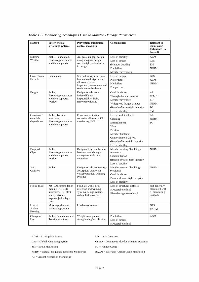
Table 1 SI Monitoring Techniques Used to Monitor Damage Parameters
Hazard Safety critical Prevention, mitigation, Consequences Relevant SI structural systems control measures monitoring
techniques (to hazard)
Extreme Weather
Jacket, Foundation, Risers/Appurtenances and their supports
Adequate air gap, design using adequate design wave height, redundancy in design
Loss of stability Loss of airgap (Member buckling Pile failure Member severance)
AGM GPS SM NFRM
Geotechnical Hazards
Foundation Sea-bed surveys, adequate foundation design, scour allowance, scour inspection, measurement of settlement/subsidence
Loss of airgap Platform tilt Pile failure Pile pull out
GPS AGM NFRM
Fatigue Jacket, Risers/Appurtenances and their supports, topsides
Design for adequate fatigue life and inspectability, IMR, remote monitoring
Crack initiation Through-thickness cracks Member severance Widespread fatigue damage
AE CFMD LD NFRM
(Breach of water-tight integrity FG Loss of stability) SM
Corrosion / materials degradation
Jacket, Topside structures, Risers/Appurtenances and their supports
Corrosion protection, corrosion allowance, CP monitoring, IMR
Loss of wall thickness Cracking Embrittlement Wear
AE NFRM FG
Erosion Member buckling Connection to SCE lost (Breach of watertight integrity Loss of stability)
Dropped Object
Jacket, Risers/Appurtenances and their supports, topsides
Design of key members for bow and dent damage, management of crane operations
Member denting / buckling / severance Crack initiation (Breach of water-tight integrity
NFRM
Loss of stability) Ship Collision
Jacket Design for adequate energy absorption, control on vessel operation, warning
Member denting / buckling / severance Crack initiation
NFRM
systems Breach of water-tight integrity Loss of stability
Fire & Blast MSF, Accommodation module, TR, EER structures, Fire/Blast walls, caissons,
Fire/blast walls, PFP, detection and warning systems, deluge system, reduce leaks sources
Loss of structural stiffness Structural overload Blast damage to steelwork
Not generally monitored with SI monitoring methods
exposed jacket legs, risers
Loss of Moorings, dynamic Load measurement GPS Station positioning system RACM Keeping
Change of Use
Jacket, Foundation and Topside structures
Weight management, strengthening/modification
Pile failure Loss of airgap Structural overload
AGM
AGM = Air Gap Monitoring LD = Leak Detection
GPS = Global Positioning System CFMD = Continuous Flooded Member Detection
SM = Strain Monitoring FG = Fatigue Gauge
NFRM = Natural Frequency Response Monitoring RACM = Riser and Anchor Chain Monitoring
AE = Acoustic Emission Monitoring
Page 7
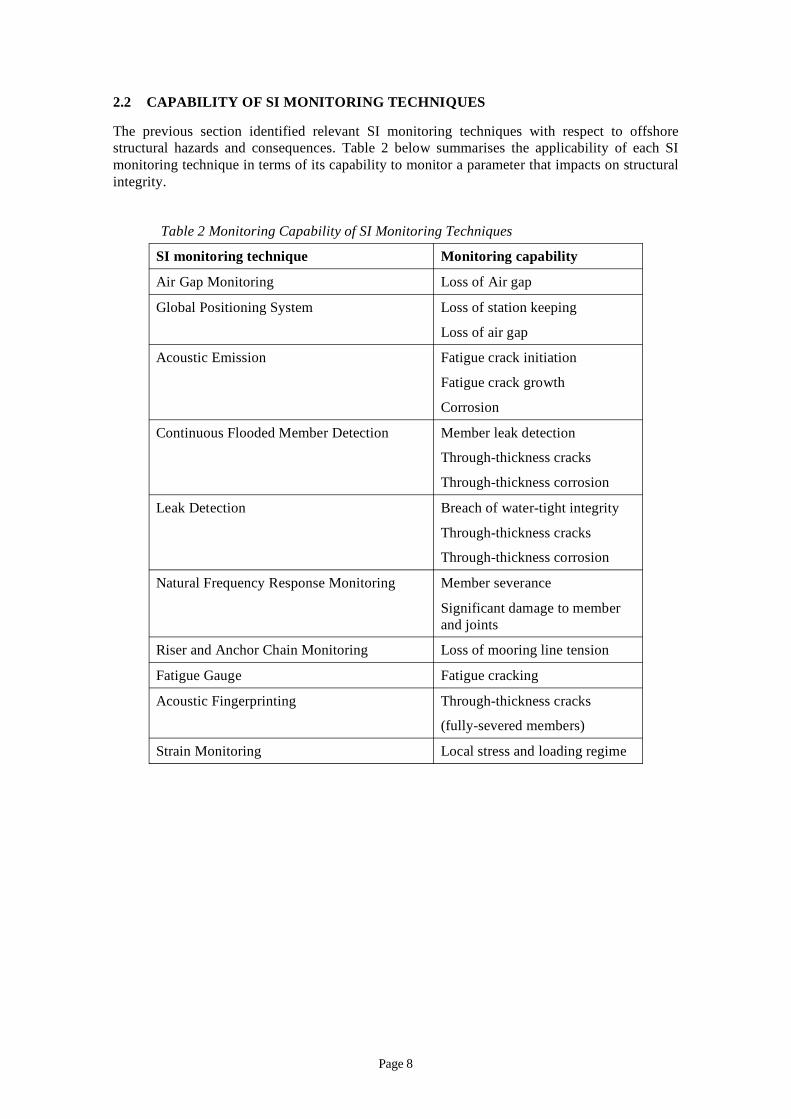
2.2 CAPABILITY OF SI MONITORING TECHNIQUES
The previous section identified relevant SI monitoring techniques with respect to offshore structural hazards and consequences. Table 2 below summarises the applicability of each SI monitoring technique in terms of its capability to monitor a parameter that impacts on structural integrity.
Table 2 Monitoring Capability of SI Monitoring Techniques
SI monitoring technique Monitoring capability
Air Gap Monitoring Loss of Air gap
Global Positioning System Loss of station keeping
Loss of air gap
Acoustic Emission Fatigue crack initiation
Fatigue crack growth
Corrosion
Continuous Flooded Member Detection Member leak detection
Through-thickness cracks
Through-thickness corrosion
Leak Detection Breach of water-tight integrity
Through-thickness cracks
Through-thickness corrosion
Natural Frequency Response Monitoring Member severance
Significant damage to member and joints
Riser and Anchor Chain Monitoring Loss of mooring line tension
Fatigue Gauge Fatigue cracking
Acoustic Fingerprinting Through-thickness cracks
(fully-severed members)
Strain Monitoring Local stress and loading regime
Page 8
3. REVIEW OF RELEVANT CODES AND STANDARDS AND PUBLISHED DOCUMENTS This section presents a brief overview of relevant codes and standards and other published documents with respect to SI monitoring.
3.1 RELEVANT CODES AND STANDARDS
A number of offshore codes and standards make reference to SI monitoring. These include:
1) ISO 19902 – Petroleum and Natural Gas Industries — Fixed Steel Offshore Structures, Section 24 [6].
This recently published ISO standard on fixed offshore installations [6] includes a section on in-service inspection and structural integrity management. In the commentary to the main section Table A.24.4-3 lists a range of inspection methods. An extract from [6] comments on measuring the air gap viz:
“Where air gap measurement devices are correctly set up, calibrated and maintained, continuous records of wave heights and tide can provide very useful information on environmental conditions. Where this can be combined with directionality data and ideally some method of estimating actions (e.g. strain gauges), the data can be used in analyses and assessment of defects and of remaining life, possibly reducing conservatisms. Satellite surveying techniques can often be used to determine levels.”
2) API “Recommended Practice for the Structural Integrity Management of Fixed Offshore Structures” [4]. This document is a draft.
Section 5.8.9 on “Non-Destructive Examination” includes a statement that the monitoring of fatigue sensitive joints and/or reported crack-like indications may be an acceptable alternative to analytical verification.
3) NORSOK “Condition Monitoring of Load-Bearing Structures” N-005, 1997 [7].
Annex A of this document includes in-service inspection methods. In the section on/selection off methods it is stated that:
“For certain purposes, Instrumentation Based Condition Monitoring, IBCM, can be used as a cost effective alternative to conventional inspection methods, particularly for monitoring areas with limited accessibility, as a supplementary mean to e.g. verify novel design solutions. Typical applications of IBCM can be strain monitoring of jacket structures, foundation behaviour during extreme storms etc.”
Strain and deflection monitoring are also included in the list of techniques.
4) ISO 16587:2004 [8] describes the performance parameters for assessing the condition of structures including types of measurement, factors for setting acceptable performance limits, data acquisition parameters for constructing uniform databases, and internationally accepted measurement guidance (e.g. terminology, transducer calibration, transducer mounting and approved transfer function techniques).
Page 9
3.2 REVIEW OF PUBLISHED DOCUMENTS
Over the last several years, a number of papers and reports have been published on the topic of SI monitoring, covering a range of different techniques. The key reports have been reviewed and a detailed review summary is provided in Appendix 4. Specific topics on which papers and reports have been written include:
– General approach to SI monitoring;
– Development of new techniques;
– Natural frequency response monitoring; and
– Acoustic emission monitoring.
This review provides useful background to the previous and future development of SI monitoring techniques.
3.3 INSPECTION REQUIREMENTS
Several standards and recommended practices list a detailed set of inspection requirements for the underwater, splash zone and topsides structures. These serve to highlight areas where SI monitoring techniques might be useful.
Underwater and splash zone
ISO 19902 [6] lists the following as inspection priorities:
– primary structural framing;
– leg/pile connections;
– external inspection of pipeline risers and supports;
– external inspection of J-tubes and supports;
– conductor guide framing;
– service caissons and supports;
– riser guards;
– boat landings and fenders;
– other secondary framing and appurtenances;
– underwater cathodic protection system; and
– any special corrosion coatings of components located in the splash zone.
The draft API Recommended Practice document - based on ISO 19902 [6] provides more details of some of the inspection requirements, namely:
– Primary structural framing: detection of excessive corrosion of welds and members, weld/joint damage (including overload and fatigue damage) and mechanical damage in the form of dents, holes, bows and gouges. Other features to be inspected for include ineffective corrosion protection systems, scour, seafloor instability, excessive or hazardous debris and excessive marine growth.
– Conductors: overall condition from the splash zone area and upwards. The conductors should be inspected for coating condition, extent of corrosion, damage, presence of shims and movement.
Page 10

– Risers: overall condition from the splash zone area and upwards. The risers should be inspected for breakdown of coatings and/or the extent of corrosion and the integrity of supporting steelwork and clamps.
– Appurtenances: damage or deterioration.
Topsides
ISO 19901-3 [9] lists the main structural items for topsides inspection. These include:
– Main deck girders and highly stiffened panels;
– Leg transitions to sub-structures (fatigue and fabrication defects);
– Module trusses and module support points;
– Accommodation module, anti-vibration mountings and support points;
– Bridges (e.g. bearing fatigue);
– Flare booms and vent stacks (supports to the main structure, strength reduction due to heat, fatigue cracks);
– Cranes including pedestals and attachments to main deck structure (e.g. fatigue);
– Drilling rigs;
– Lifeboats and other EER equipment e.g. davits;
– Helideck;
– Fire protection systems, coatings (e.g. PFP);
– Corrosion protection systems (paint and coatings);
– Access routes, floors and gratings; and
– Supports for equipment particularly any safety critical systems.
Page 11
4. REVIEW OF SI MONITORING TECHNIQUES This section summarises the basic information available on the SI monitoring techniques identified in Section 2.2.
Due to the bespoke nature of the systems, it has not been possible to include cost estimates for the different technologies in this report.
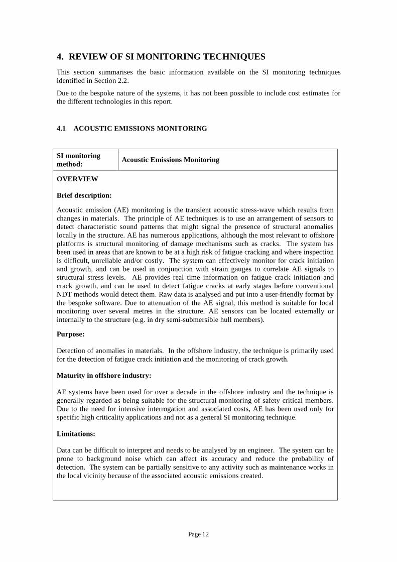
4.1 ACOUSTIC EMISSIONS MONITORING
SI m s M
( ) -
.
/j
-
r . -
can
onitoring method: Acoustic Emission onitoring
OVERVIEW
Brief description:
Acoustic emission AE monitoring is the transient acoustic stress wave which results from changes in materials. The principle of AE techniques is to use an arrangement of sensors to detect characteristic sound patterns that might signal the presence of structural anomalies locally in the structure. AE has numerous applications, although the most relevant to offshore platforms is structural monitoring of damage mechanisms such as cracks The system has been used in areas that are known to be at a high risk of fatigue cracking and where inspection is difficult, unreliable and or costly. The system can effectively monitor for crack initiation and growth, and can be used in con unction with strain gauges to correlate AE signals to structural stress levels. AE provides real time information on fatigue crack initiation and crack growth, and can be used to detect fatigue cracks at early stages before conventional NDT methods would detect them. Raw data is analysed and put into a user friendly format by the bespoke software. Due to attenuation of the AE signal, this method is suitable for local monitoring over several metres in the structure. AE sensors can be located externally ointernally to the structure (e.g in dry semi submersible hull members).
Purpose:
Detection of anomalies in materials. In the offshore industry, the technique is primarily used for the detection of fatigue crack initiation and the monitoring of crack growth.
Maturity in offshore industry:
AE systems have been used for over a decade in the offshore industry and the technique is generally regarded as being suitable for the structural monitoring of safety critical members. Due to the need for intensive interrogation and associated costs, AE has been used only for specific high criticality applications and not as a general SI monitoring technique.
Limitations:
Data can be difficult to interpret and needs to be analysed by an engineer. The system can be prone to background noise which affect its accuracy and reduce the probability of detection. The system can be partially sensitive to any activity such as maintenance works in the local vicinity because of the associated acoustic emissions created.
Page 12
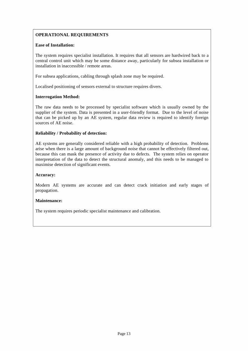
OPERATIONAL REQUIREMENTS
Ease of Installation:
The system requires specialist installation. It requires that all sensors are hardwired back to a central control unit which may be some distance away, particularly for subsea installation or installation in inaccessible / remote areas.
For subsea applications, cabling through splash zone may be required.
Localised positioning of sensors external to structure requires divers.
Interrogation Method:
The raw data needs to be processed by specialist software which is usually owned by the supplier of the system. Data is presented in a user-friendly format. Due to the level of noise that can be picked up by an AE system, regular data review is required to identify foreign sources of AE noise.
Reliability / Probability of detection:
AE systems are generally considered reliable with a high probability of detection. Problems arise when there is a large amount of background noise that cannot be effectively filtered out, because this can mask the presence of activity due to defects. The system relies on operator interpretation of the data to detect the structural anomaly, and this needs to be managed to maximise detection of significant events.
Accuracy:
Modern AE systems are accurate and can detect crack initiation and early stages of propagation.
Maintenance:
The system requires periodic specialist maintenance and calibration.
Page 13
4.2 LEAK DETECTION
SI m L D
/)
-
-
e -
) an a m
– / ;
– ;
– -sub .
– / [2] f
-
[1] -sub jack-unity.
onitoring method: eak etection
OVERVIEW
Brief description:
In its simplest form, this monitoring system uses a sensor to detect water and then raises an alarm via an audible visual unit. The technology in the system can vary significantly from early inundation alarms (fluid level switches to more advanced systems such as field effect detector cells which produce a micro electrical field that detects slight disruptions caused by water.
Purpose:
Detection of water ingress in dry areas typically in semi submersibles. A secondary system such as a CCTV system is usually required to identify the cause of the water ingress e.g. breach of hull integrity or pipe failure.
Maturity in offshore industry:
Simple alarm systems have been used for a number of decades in the offshore industry to warn of high bilg water in ship hulls. Semi submersible offshore platforms have also employed leak detectors, although these systems appear to have been bespoke designs and are often fairly dated.
A number of companies offer advanced leak detection systems, but their primary business is not the offshore industry. These systems combine sensors from numerous zones (up to 32 typical and raise alarm from central monitoring system. The monitoring system indicates in which zone the water leak has been detected. This syste is accurate in identifying the leakage area and is also more sensitive to leakage than the simple alarm systems.
Limitations:
some systems sensor options rely on a clean environment
may be affected by condensation or humid environment
extensive cabling may be required as wireless systems are not well suited to typical semi mersible environments
Regulatory requirement:
HSE Information Sheet Offshore Information Sheet 8 2007 recommends that owners and operator o monohull FPSO and FSU installations review their risk assessments for the flooding of machinery spaces below water level, and ensure that effective means are provided for the detection and control of flooding. It also suggests that, if these areas are unmanned for any length of time, it is good practice to install CCTV that displays in the continuouslymanned control room.
DNV requires an approved leak detection system for semi mersibles and ups when the fatigue utilisation index exceeds
Page 14
OPERATIONAL REQUIREMENTS
Ease of Installation:
It is likely that the system would require all sensors to be wired back to the monitoring system positioned in the manned control room. Wireless systems are available but the suitability of the structure has to be assessed on an individual basis, and it is likely that the steelwork in an offshore structure would significantly reduce the range of these systems and increase the interference.
Interrogation Method:
A typical system would raise an alarm when water is detected and will indicate in which zone this occurs.
Reliability / Probability of detection:
The technology appears to be relatively mature and there appears to be no significant reliability issues with latest systems.
Accuracy:
There are a number of different sensor options, some of which can detect water levels of 3mm (measured from the floor level).
Maintenance:
Modern water sensors have no moving parts. Consequently, they require little or no maintenance. The system should however be tested in line with the relevant codes of practice [1].
Page 15

4.3 AIR GAP MONITORING
SI monitoring method: Air Gap Monitoring
OVERVIEW
Brief description:
The air gap is defined as the positive difference between the lowest point of the underside of the cellar deck and the crest height of an extreme wave for a given return period (often 100 years). The purpose for monitoring the air gap is to establish whether the platform foundations are suffering from subsidence, and also to establish if a positive air gap exists. The methodology for calculating the air gap has changed considerably over the past decade. Simple methods such as a tape measure from the cellar deck have been used, which in time have been replaced by radar measurement. Measured values are recorded and averaged over a given time period. A value for the air gap can then be calculated. These methods can yield ambiguous results in practice whilst also suffering from poor repeatability (due to ocean surges, tidal changes etc.), and this complicates detection of trends over a long period of time.
Modern methods use GPS to monitor the air gap. The first time the absolute level height is measured, a reference point is established that will be used for all repeat readings. This increases the repeatability and reduces inaccuracies between surveys. The GPS measurement from the reference point to the underside of the cellar deck is also measured using GPS on the first visit. This is to give an exact as-built measurement, which is important because dimensions can sometimes vary considerably from detailed drawings.
Purpose:
The primary application of this technique is to measure the air gap at specified intervals, for example, every 3 years. The results are then compared and any issues with reduced air gap raised.
Some companies offer near real-time continuous monitoring services. These systems are important for seismically active regions or platforms that are known to be at a continuous risk due to local conditions. In general a periodic survey is sufficient.
Maturity in offshore industry:
Airgap monitoring has been carried out for over a decade, but the methods used have changed significantly over time. This is however a standard monitoring procedure now, and is widely applied in the offshore industry.
Limitations:
Requires specialist contractor to carry out measurements
OPERATIONAL REQUIREMENTS
Ease of Installation:
Periodic monitoring methods do not require installation of hardware.
Page 16
Interrogation Method:
The contractor should provide the survey results in a post processed format and minimal interpretation should be required.
Reliability / Probability of detection:
Standard equipment is used for the survey and reliability is not considered problematic.
Accuracy:
To determine a reliable GPS reading the equipment is usually in place for 24hrs. Once the GPS value for the reference point above mean sea level has been determined there are various analytical methods for calculating the true air gap that are beyond the scope of this report. As mentioned in Section 4.4 the real time / instantaneous accuracy of a system using the standard GPS network is only approximately 10m which is insufficient for this purpose.
Because real-time accuracy is less important for this application, the corrections can be calculated at a later date after data has been collected. Using this method an accuracy of up to 50mm can be achieved.
Maintenance:
Any maintenance required to the measurement system would be carried out by the specialist contractor.
Page 17
4.4 GLOBAL POSITIONING SYSTEM MONITORING
SI monitoring method: Global Positioning System Monitoring
OVERVIEW
Brief description:
The position of a floating structure can be monitored using a Global Positioning System (GPS). The basic GPS technology is not new and is well proven. The US DoD’s GPS network, available to all, has real-time accuracy in the region of 10m horizontally. Such systems require hardware in the form of a GPS receiver and a user interface. Software is then required that can be tailored to meet user requirements. The basic accuracy of the system can be improved using a number of different techniques.
Purpose:
The technology is especially useful to any floating structure where exact positioning is important. Two applications are as follows:
– Semi-submersibles – the structure’s location can be monitored and an alarm raised if it exceeds a predefined allowable deviation from a reference point. This arrangement would alert the operator to any significant issues with the mooring.
– FPSOs – to continuously monitor the position of the vessel relative to a reference point. The relative position can then be used, for example, to ensure that the stresses in the risers are not excessive.
Maturity in offshore industry:
GPS is widely used in the offshore industry and is generally a mature technology.
Limitations:
Ongoing subscription required for live corrections, which increase accuracy.
OPERATIONAL REQUIREMENTS
Ease of Installation:
Topsides installation of permanent equipment is required.
Interrogation Method:
A number of companies offer complete bespoke packages that will monitor the position of a structure and log the data, using enhanced GPS services. The system will also raise alarms based on user defined parameters. The maintenance, installation, operation guide and continuous support of the system can all be provided by the manufacturer. Correction data is delivered real-time to the receiver via communication satellites. The correction data enhances the accuracy, reliability and integrity of the standard GPS system.
Page 18
Reliability / Probability of detection:
This is a mature technology and there are no problems with reliability or probability detection envisaged.
Accuracy:
The accuracy for premium services can be improved to approximately 10cm horizontally, with more basic packages offering accuracies in the order of 1m. It should be noted that the real-time accuracy of GPS in Europe is increasing with systems such as the European Geostationary Navigation Overlay (EGNOS) being developed.
Maintenance:
Maintenance requirements for GPS systems are generally minimal.
Page 19
4.5 FATIGUE GAUGE
SI monitoring method: Fatigue Gauge
OVERVIEW
Brief description:
CrackFirst™ is a fatigue damage sensor system specifically designed for welded steel structures and was patented in 1990. It was developed within a DTI funded collaborative project managed by TWI and is currently available from Strainstall. The CrackFirst™ sensor itself consists of a thin steel shim, 0.25mm thick which can be attached to the target structure, close to a critical joint (up to 10mm from the toe). Under the action of cyclic loading in the structure, a fatigue pre-crack at the centre of the shim (introduced during manufacture) extends by fatigue growth.
Purpose:
The sensor design is such that the extent of crack growth in the shim is proportional to the cumulative fatigue damage for a welded joint subjected to the same loading. This could provide a representative record of cumulative fatigue damage occurring on a structure (assuming the sensor can be located close to the weld toe). In addition, remote operation is possible, and data can be downloaded via a wireless link. The availability of fatigue data could improve maintenance scheduling and setting of inspection intervals.
Maturity in offshore industry:
Limited development in the offshore industry.
Limitations:
– Attachment to the structure may be difficult depending on conditions, particularly underwater;
– Installation of the sensor sufficiently close to the weld toe for it to respond to the fatigue loads causing damage in the structure may prove difficult;
– Sensors may prove vulnerable to offshore environmental conditions;
– Failure to detect loss of adhesion may lead to false negatives in measurements;
– Sensors cannot be replaced when damaged.
OPERATIONAL REQUIREMENTS
Ease of Installation:
Attachment of the sensor is by either a combination of threaded studs or by adhesive bonding. To protect the sensor from mechanical damage and corrosion, a sealed enclosure is fitted over the whole unit. The sensor is pre-tensioned after installation using a specially designed rig to ensure that it responds to both tensile and compressive applied load cycles, in the same way as a welded joint containing tensile residual stress.
Page 20
Interrogation Method:
An on-board electronics unit can check the sensor status regularly and record the data in a memory which can be downloaded to a laptop PC via a wireless link or to a data logger. The unit can be powered from an on-board battery.
Reliability / Probability of detection:
Limited information to date.
Accuracy:
Claims to bound a class F detail; however, there is a significant inherent scatter in fatigue data and this should be considered in making comparison with the joint under investigation.
Maintenance:
Limited information available for offshore applications.
Page 21
4.6 CONTINUOUS FLOODED MEMBER DETECTION: INTERNAL
SI m
O
B
(
--
the
as
y
onitoring method: Continuous Flooded Member Detection: Internal
VERVIEW
rief description:
A device is placed inside a nominally dry tubular member. If the member becomes flooded the salinity of the solution activates a galvanic cell which remains completely passive when dry). The power of the current is used to generate an acoustic signal which is transmitted and received at the topsides. Each tubular member will contain a device that will generate a unique signal and therefore upon reception of a signal, the location of the damage will be immediately identifiable.
This method would be very realisable for new builds employing through water telemetry. Whilst this is not as elegant a solution as the through steel telemetry (because it requires the use of a hydrophone) it is a very practical solution.
Demonstration of the device’s reliability would add considerably to the overall cost of setting up a business and may be an obstacle that would require significant investment. Therefore, a significant opportunity across a number of installations would probably be needed to make
business economically viable.
Purpose:
Continuous detection for through wall defects. Similar to flooded member detection but is continuous and therefore the lack of knowledge of asset integrity in the periods between inspections is avoided.
Maturity in offshore industry:
None. Untried and untested at full scale.
Limitations:
Only suitable for new build.
Limitations on signal attenuation (due to losses into the water) can be avoided by using lower frequencies. However, in going to lower frequencies there is a trade off on power (power required to generate lower frequencies is higher). Higher power may be required at lower frequencies they tend to be competing with the background noise. However, a pure sinusoid may well be identifiable through high levels of background noise.
Lower frequency signals tend to require transducers that are more expensive and possibly less reliable. Magnetic loop transducers may avoid this issue but this has not been tested.
Higher frequency signals can be easily transmitted through the water. This would require detection by the use of a hydrophone.
The downside of transmitting through the water is that installing a hydrophone introduces additional design, maintenance and operational burdens which may be viewed unfavourablat the FEED and design stages at which the correct implementation would need to be built in to any new build incorporating this technology.
Page 22
Can only be used in saline waters.
Members in the splash zone are difficult to monitor.
Regulatory requirement:
None
OPERATIONAL REQUIREMENTS
Ease of Installation:
Can only be installed during the construction phase. Devices have to be placed inside tubular members such that they will remain in a position to guarantee good acoustic contact during load out and installation phase (including piling). They would have to be positioned such that they did not become damaged by fabrication welds.
Interrogation Method:
The receiving device listens continuously. Upon hearing a signal an alarm is raised.
Reliability / Probability of detection:
Unproven and difficult to prove in practice.
A major concern is clearly the reliability of the device itself. As one is unable to access the device once it is installed, it is difficult to claim that the device’s PFD (Probability of Failure on Demand) is very low. Discussions took place on ways to counter this problem and a brief summary of the points raises are as follows:
– Device is entirely passive - no current flows until the cell becomes wetted;
– Can use high integrity, military standard type components to withstand vibration loads during piling;
– Can design an arrangement such that any slippage during piling will either not happen or if it does it will not compromise acoustic contact;
– Device could be shipped with a battery that would enable a self-test every several weeks. This would counter concerns over not being able to identify whether the device was operational at the start of life and may provide some assurance into the life of the product; but the duration of this assurance cannot be guaranteed beyond probably 10 years.
– Redundancy – the cost of the hardware is low and their weight also low so it may be possible to install two (or more) identical devices into each member;
– Reliability proving programme - a set of devices installed inside dry tubular members would be kept under controlled conditions for a long period of time. Periodically, a number of tubulars would be flooded and their performance recorded over time. This would enable the building of an operating history. Evidently this would create a cost burden to the programme.
Page 23
-
– -
L /m /m /m
L /m /m /m
LJ j j j
LJ j
Accuracy:
If the devices are reliable and installed correctly the accuracy could be high.
Maintenance:
Maintenance of subsea device not possible once installed.
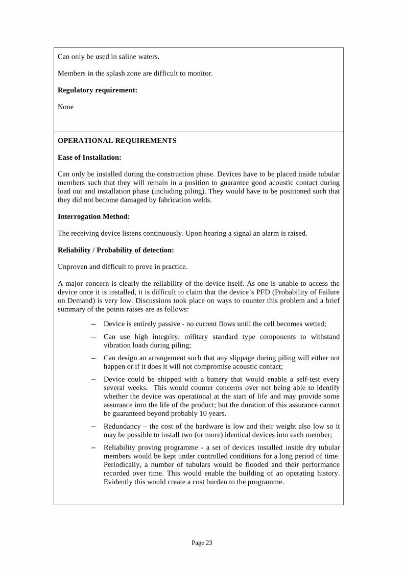
Illustrations
The device was tested for high frequencies using the specimen shown below. This was designed to maximise the possible submerged depth and to demand the signal to pass through two nodes with a change in direction at each.
Mid scale specimen used for experiments
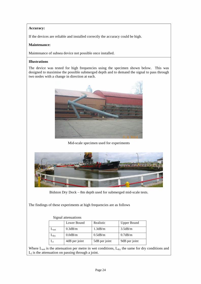
Bidston Dry Dock 8m depth used for submerged mid scale tests.
The findings of these experiments at high frequencies are as follows
Signal attenuations Lower Bound Realistic Upper Bound
wet 0.3dB 1.3dB 3.5dB
dry 0.0dB 0.5dB 0.7dB
4dB per oint 5dB per oint 9dB per oint
Where Lwet is the attenuation per metre in wet conditions, Ldry the same for dry conditions and is the attenuation on passing through a oint.
Page 24
-
0 0
atte
nuat
ion
lli ic
-
It can
-
(m)
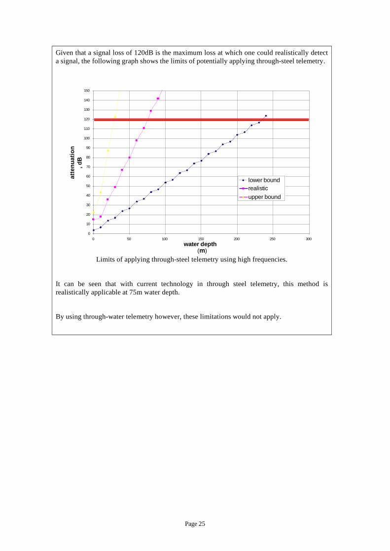
Given that a signal loss of 120dB is the maximum loss at which one could realistically detect a signal, the following graph shows the limits of potentially applying through steel telemetry.
10
20
30
40
50
60
70
80
90
100
110
120
130
140
150
50 100 150 200 250 300 water depth
, dB
ower bound rea stupper bound
Limits of applying through steel telemetry using high frequencies.
be seen that with current technology in through steel telemetry, this method is realistically applicable at 75m water depth.
By using through water telemetry however, these limitations would not apply.
Page 25
4.7 CONTINUOUS FLOODED MEMBER DETECTION: EXTERNAL
SI monitoring method: Continuous Flooded Member Detection: External
OVERVIEW
Brief description:
A device is clamped to the outside of a nominally dry tubular member. The device transmits a high frequency acoustic signal through the member and detects attenuation of the signal at regular intervals. A highly attenuated signal would indicate the presence of water inside the member. Upon detecting a change, the device would send an alarm signal through the steel or the water which would be indicated in the control room.
Purpose:
– Continuous detection for through-wall defects;
– Essentially flooded member detection but is nearly continuous and therefore the lack of knowledge of asset integrity in the periods between inspections is avoided.
Maturity in offshore industry:
None. Untried. Untested. This was mooted at various industry forums (eg NESTA) but received no financial support. Major concerns were raised over reliability.
Limitations:
– Battery life – it is possible to reduce the power requirements by only using the system periodically (e.g. every week) as opposed to continuously. However, battery manufacturers seem to have a limit of ten years on battery reliability. This would infer the requirement for a battery change out programme which would therefore require a diver or ROV intervention. The advantage over a normal FMD programme, is that the monitoring is continuous with associated increased claims on platform reliability.
– Members in the splash zone are difficult to monitor;
– If the devices are too bulky they will introduce extra load into the structure.
Regulatory requirement:
None
OPERATIONAL REQUIREMENTS
Ease of Installation:
One of the obstacles to this being realisable is the issue of designing and installing a clamp that will maintain the position of the transducer through the life. Consideration of the large loads in the wave action zone would need to be given and it will be difficult to demonstrate high reliability given the difficulty of this problem.
Page 26
The overall hydrodynamic profile of the device should minimise the attraction of any extra drag forces that could be transmitted into the jacket structure.
Interrogation Method:
The continuous FMD device detects changes to the reflected signal periodically. Upon detecting a change an alarm signal is transmitted to the control room.
Reliability / Probability of detection:
Unproven.
It might be possible to argue that the probability of detection would be similar to that for FMD applied in the field. However, the electronics in this device would be performing the interpretation of the signal and would therefore need to be high integrity with associated cost implications.
Accuracy:
If the device was reliable and the devices installed correctly the accuracy could be potentially as high as that for FMD – approx 90%. However, concerns over signal drift, clamp robustness and the electronic processing and interpretation of the signal could significantly erode this limit if these points were not addressed appropriately.
Maintenance:
Possible by ROV and diver only. Battery change-out may be required.
Page 27
,
4.8 NATURAL FREQUENCY RESPONSE MONITORING
SI m ( )
O
j
j
, Hz
Hz
llel
pl
onitoring method: Natural Frequency Monitoring NFRM
VERVIEW
Brief description:
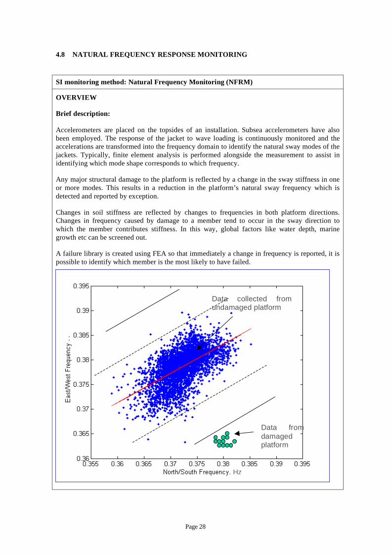
Accelerometers are placed on the topsides of an installation. Subsea accelerometers have also been employed. The response of the acket to wave loading is continuously monitored and the accelerations are transformed into the frequency domain to identify the natural sway modes of the ackets. Typically, finite element analysis is performed alongside the measurement to assist in
identifying which mode shape corresponds to which frequency.
Any major structural damage to the platform is reflected by a change in the sway stiffness in one or more modes. This results in a reduction in the platform’s natural sway frequency which is detected and reported by exception.
Changes in soil stiffness are reflected by changes to frequencies in both platform directions. Changes in frequency caused by damage to a member tend to occur in the sway direction to which the member contributes stiffness. In this way, global factors like water depth, marine growth etc can be screened out.
A failure library is created using FEA so that immediately a change in frequency is reported, it is possible to identify which member is the most likely to have failed.
Data co cted from undamaged p atform
Data from damaged
atform
Page 28
Purpose:
To continuously monitor for the change in platform frequency and then to identify the most likely failed members. NFRM can be used to detect pre- and post-effects of incidents such as an extreme storm, an earthquake, a ship collision or a dropped object. It can also be used to detect changes in foundation stiffness.
Maturity in offshore industry:
Mature technique, which has been in operation since late 1970’s on a number of platforms. A system was installed on Ninian South following a member severance. Following repair the platform’s frequency was detected as increasing.
Discussions with UK vendors revealed that there are at least twenty platforms with natural frequency monitoring systems installed worldwide.
Confidentiality prevents the naming of all of these but on the UKCS there are some 7 systems, 3 in the rest of Europe with the remainder split between Mexico, Canada, Caspian, and West Africa.
It is worth noting that one vendor mentioned a recent upturn in business with eight orders being placed in the last 12 months.
Limitations:
The method is only sensitive enough to detect changes in frequency of approximately 0.5%. This means that the method cannot detect minor damage such as small defects. A Joint Industry Project (JIP) performed in which HSE participated showed that in low redundancy jackets with single diagonal bracing systems an 80% circumferential through-wall defect is detectable using this method.
However, the limit in sensitivity means that the method is less easy to employ for heavier jackets with high redundancy bracing schemes. For jackets with more than 4 legs the detection of damage may become more difficult. It may be possible to incorporate a larger array of accelerometers and to link them together in the time domain to monitor modal shapes as well as frequencies in order to identify damage.
Page 29
R
] i
–
– -
– -
/ :
)
an
a
–
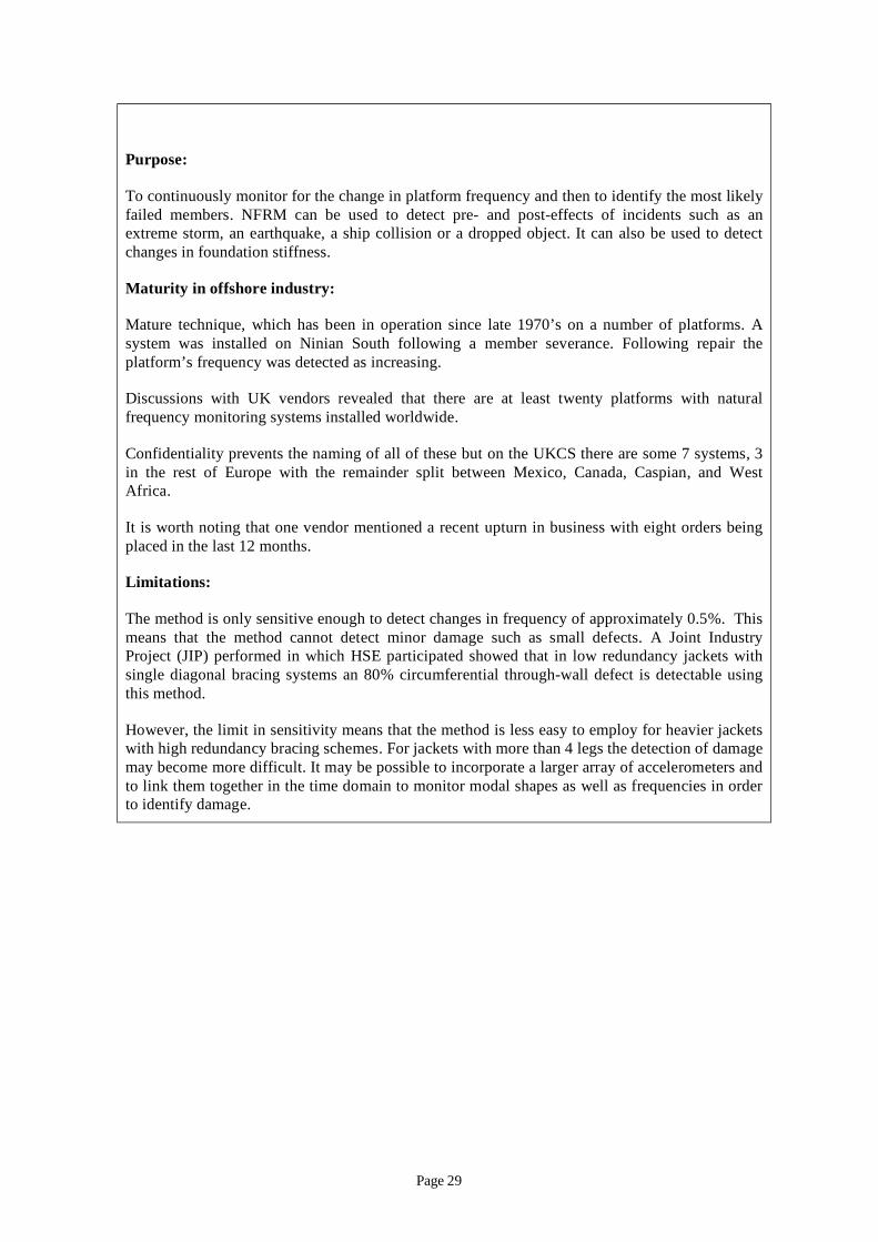
Further, as illustrated above, members which cause small changes in frequency tend not to be structurally significant members. It is usually the members which cause a large reduction in structural strength that also cause a large change in frequency.
egulatory requirement:
None at present, however the publication of API RP 2SIM [10 s expected in 2008 which includes guidance on the installation of natural frequency monitoring systems
OPERATIONAL REQUIREMENTS
Ease of Installation:
In the hands of an experienced 3rd party vendor, relatively straightforward.
Self contained units placed on the topsides these are already designed to be intrinsically safe.
Cabled back to PCs in control room or hard wired through to the beach.
Interrogation Method:
Daily interrogation of the data. Changes reported by exception.
Reliability Probability of detection
These changes for different platforms and members. Usually NFRM should be accompanied by finite element analysis (FEA which identifies the expected changes in frequency for severing each member. If the FEA predicts that members have frequency shifts of less than 0.5% then this may be undetectable failure. Members with changes less than 1% may also require examination of more than one sway mode or a torsional mode.
Reduction
in strength
OLM pplicable
Change in frequency
1.0 Acceptable reduction in strength
Detectable Limit
OLM cannot detect failure of this member but it is not structurally critical OLM definitely not applicable
OLM Online Monitoring
Page 30
-
-
jj
- - j - -
Accuracy:
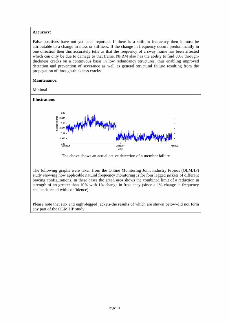
False positives have not yet been reported. If there is a shift in frequency then it must be attributable to a change in mass or stiffness. If the change in frequency occurs predominantly in one direction then this accurately tells us that the frequency of a sway frame has been affected which can only be due to damage to that frame. NFRM also has the ability to find 80% throughthickness cracks on a continuous basis in low redundancy structures, thus enabling improved detection and prevention of severance as well as general structural failure resulting from the propagation of through thickness cracks.
Maintenance:
Minimal.
Illustrations
The above shows an actual active detection of a member failure
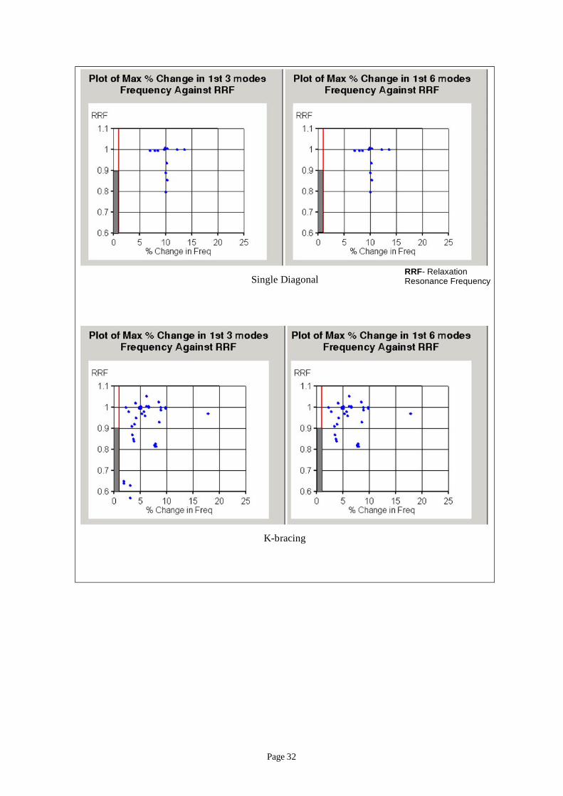
The following graphs were taken from the Online Monitoring Joint Industry Pro ect (OLMJIP) study showing how applicable natural frequency monitoring is for four legged ackets of different bracing configurations. In these cases the green area shows the combined limit of a reduction in strength of no greater than 10% with 1% change in frequency (since a 1% change in frequency can be detected with confidence) .
Please note that six and eight legged ackets the results of which are shown below did not form any part of the OLM JIP study.
Page 31
K-
RRF- l iSingle Diagonal
bracing
Re axat on Resonance Frequency
Page 32
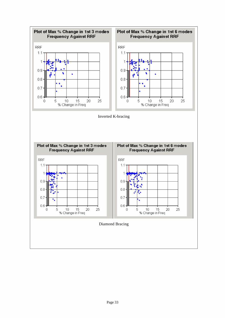
- ingInverted K brac
Diamond Bracing
Page 33
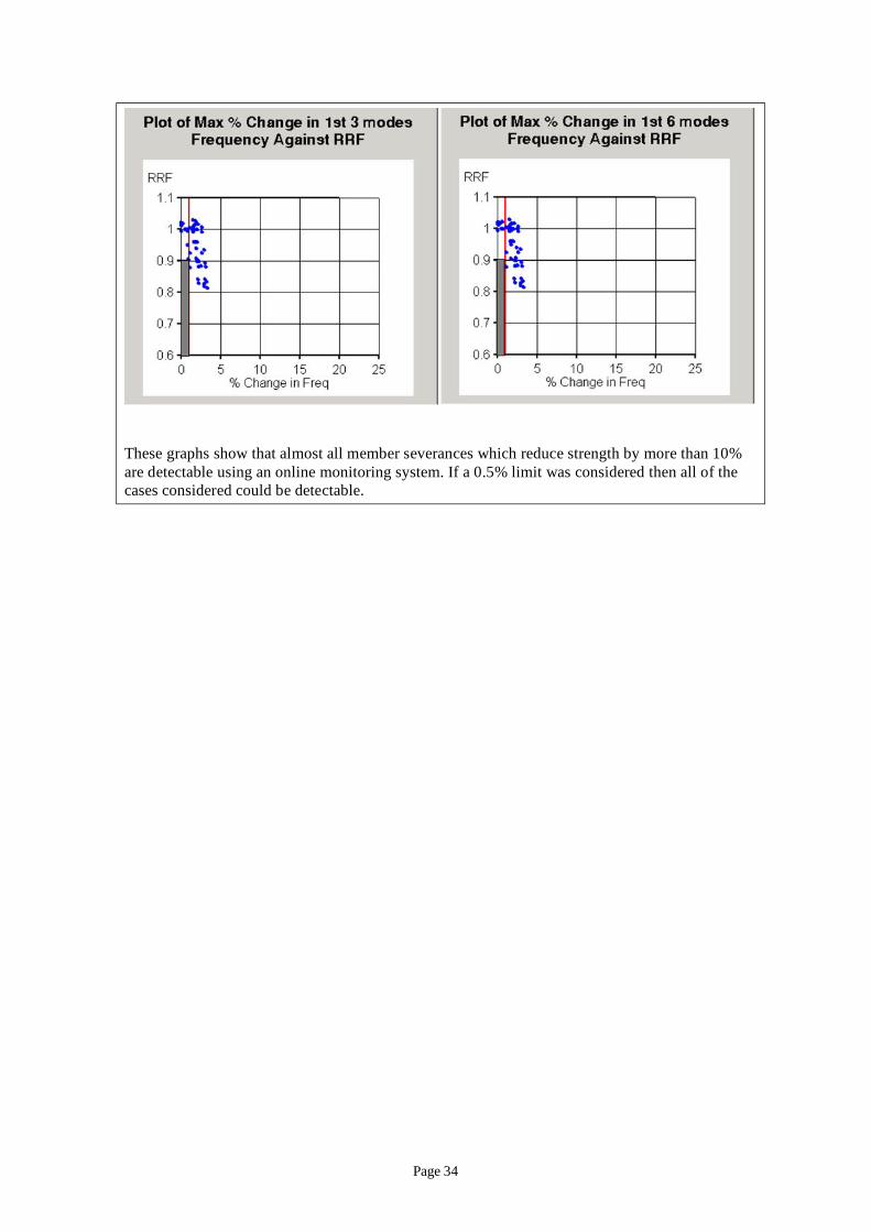
These graphs show that almost all member severances which reduce strength by more than 10% are detectable using an online monitoring system. If a 0.5% limit was considered then all of the cases considered could be detectable.
Page 34
4.9 ACOUSTIC FINGERPRINTING
SI monitoring method: Acoustic Fingerprinting
OVERVIEW
Brief description:
Acoustic fingerprinting involves the transmission of acoustic signals into a jacket structure at locations above the maximum water level. The signal is generally transmitted into one or more legs. Receivers are placed also above the water level and ‘listen’ to the signal that is returned, reporting and interpreting changes to diagnose damage from the change in signal.
Purpose:
This technique would enable continuous SI monitoring to be retrofitted onto any platform. It relies on the complex behaviour of acoustic signals through the steel, with reflections and refractions occurring at section changes and nodes. The technique relies upon the fact that if the transmitted signal is self-same, then so will be the received signal.
Research has been carried out to diagnose failure by using time of flight computation on the received signals. This work claims that the technique would be able to identify the member or possibly a structural locale in which the damage is located.
Maturity in offshore industry:
Untested in major structures. Research work isolated to laboratory scale tests at present.
Limitations:
Lab work introduced major damage (i.e. sawing through members). This is considered to be unrepresentative of damage induced by fatigue in which opposite faces of the defect may well remain in contact for most of the time.
If the technique were to be proven it is likely that it would be sensitive enough to detect fully-severed members only.
Regulatory requirement:
None
OPERATIONAL REQUIREMENTS
Ease of Installation:
In the hands of experts relatively easy to install, requiring no access to restricted areas. Transmitting and receiving equipment generally installed above splash zone.
Cabling may be required back to Control Room.
Page 35
/ :
– ].
// / /
Interrogation Method:
Algorithms which analyse the received signal in the frequency domain are interrogated for changes brought about by the presence of an exception. The signal may be transmitted as often or as infrequently as desired.
Reliability Probability of detection
Unproven.
Accuracy:
Unproven.
Maintenance:
Claimed that the device will be standalone, but in order to meet performance standards it is expected that the equipment will require periodic calibration.
Illustrations
The research work carried out to develop this technique is illustrated by reference to HSE Research Report 325 Cost Effective Structural Monitoring [11
http: www.hse.gov.uk research rrhtm/rr325.htm
Page 36
4.10 RISER AND ANCHOR CHAIN MONITORING
SI monitoring method: Riser and Anchor Chain Monitoring
OVERVIEW
Brief description:
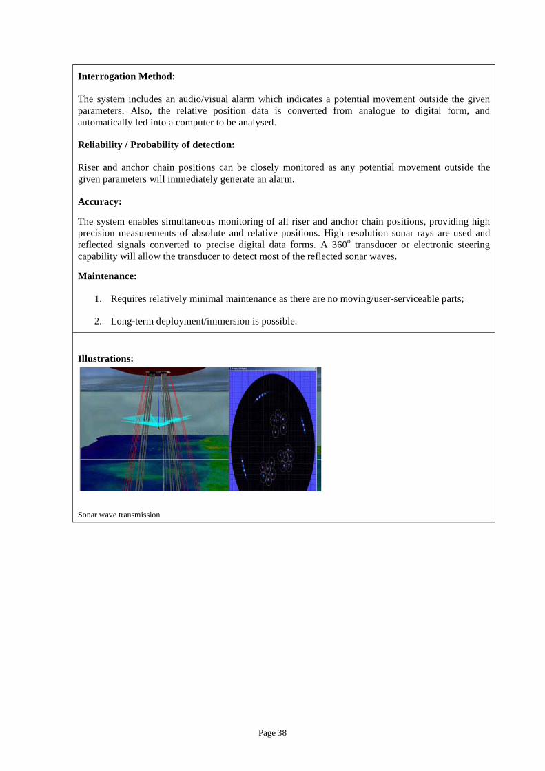
Riser and anchor chain monitoring systems consist of a sonar array positioned beneath the platform, which emits signals in and around the horizontal plane. The system then detects and analyses reverberating signals from items that are within the monitoring region. This data can then be used to determine the precise location of these items and to continuously monitor their position. If there is a problem with the mooring of a platform, the system will alert the operator to the issue immediately via an audio/visual alarm.
Purpose:
The purpose of this technique is to monitor the position of risers and anchor chains and alert the operator to any displacements outside of predefined limits. In addition, failure-analysis can be performed using the resulting computerised data.
Maturity in offshore industry:
This technique is widely used in the offshore industry. The number of beams, beam resolution, range, transducer type, etc. can be altered to suit the particular application environment.
Limitations:
Beam scatter: The transducer may not always detect a considerable amount of the reflected beam for numerous reasons (e.g. the riser or anchor chain may be at a non-reflecting angle or the transmitter may be located too far away from the riser or anchor chain, leading to reflective sonar wave degradation);
Feasibility: It may not always be feasible to locate an RACM system in certain offshore environments. Technical constraints may arise from factors such as the presence of other unwanted obstacles within close proximity to the system.
OPERATIONAL REQUIREMENTS
Ease of Installation:
The system is relatively easy to install as there are no mechanically moving parts. Also, long-term deployment is possible.
Two main deployment techniques:
1. Deploy the system externally to the pattern of risers or anchor chains and then monitor the returning signals using a pair of transducers;
2. Deploy the system within the centre of the risers and anchor chains and then monitor using a compact 360o conformal sonar transducer array.
Page 37
/
/
r
o
1. / - ;
2. - /
Interrogation Method:
The system includes an audio visual alarm which indicates a potential movement outside the given parameters. Also, the relative position data is converted from analogue to digital form, and automatically fed into a computer to be analysed.
Reliability Probability of detection:
Riser and anchor chain positions can be closely monitored as any potential movement outside the given parameters will immediately generate an alarm.
Accuracy:
The system enables simultaneous monitoring of all rise and anchor chain positions, providing high precision measurements of absolute and relative positions. High resolution sonar rays are used and reflected signals converted to precise digital data forms. A 360 transducer or electronic steering capability will allow the transducer to detect most of the reflected sonar waves.
Maintenance:
Requires relatively minimal maintenance as there are no moving user serviceable parts
Long term deployment immersion is possible.
Illustrations:
Sonar wave transmission
Page 38

4.11 STRAIN MONITORING
SI monitoring method: Strain Monitoring
OVERVIEW
Brief description:
Strain monitoring is carried out to determine the stress or loading regime in part of a structure. There are a number of strain measurement techniques available including conventional strain gauging, fibre optics and stress probes. Typically, gauges are installed away from stress concentrations and in such a way that the global structural loading can be determined (e.g. 4 quadrants around a brace).
Purpose:
To monitor local stress variations to provide information on the local structural loading and/or stress regime-local hot spot stresses can then be determined from numerical modelling.
Strain monitoring in areas of steep stress gradients (e.g. at stress concentrations) is not generally carried out due to the sensitivity of the results to the gauge location.
Large strain gauges designed for uniaxial strain measurement may be useful for strain measurement on hull and deck plates.
Maturity in offshore industry:
Widely applied across many industries including the offshore industry. A large amount of relevant documentation is available, e.g. [12].
Limitations:
– Most methods only applicable for measuring stress variations and not absolute stress levels;
– Equipment can be sensitive to damage by the environment especially cabling up the legs through the splash zone;
– Requires calibration and can be sensitive to drift over time;
– Sensitive to positioning of gauge in areas with steep stress gradients.
OPERATIONAL REQUIREMENTS
Ease of Installation:
Installation of strain gauges is generally not problematic, but appropriate surface preparation is required. Cabling requirements may complicate installation in remote locations and interactions with the environment should be considered.
Interrogation Method:
Usually through a computerised system which provides a time-strain history.
Reliability / Probability of detection:
Page 39

Widely applied and generally reliable.
Accuracy:
Generally high. Can be affected by external causes such as wiring interference, temperature variations, bridge set-up and other factors.
Maintenance:
Requires periodic maintenance to ensure integrity and connection of strain gauges.
Page 40
4.12 COMPARISON OF CHARACTERISTICS OF SI MONITORING METHODS
A tabulated comparison of the characteristics of the SI monitoring systems discussed in the previous sections is provided in Appendix 2. This section provides a comparison of these characteristics for each monitoring method.
Maturity in offshore industry
A number of monitoring methods have been used for a decade or more in the offshore industry, and can be regarded as mature technologies. These include:
– Acoustic emission monitoring;
– Air gap monitoring;
– GPS monitoring;
– Leak detection;
– Natural frequency response monitoring;
– Strain monitoring; and
– Riser and anchor chain monitoring.
Although some of these methods have been used for some considerable time, their application has generally been on bespoke applications. This is particularly the case for acoustic emissions monitoring and natural frequency response monitoring.
Limitations
Limitations are generally specific to each method and are not compared here.
Ease of installation
The installation requirements of monitoring methods can broadly be arranged into three groups as follows:
Requires installation equipment above splash zone only:
– Acoustic fingerprinting;
– Air gap monitoring;
– Global positioning system monitoring; and
– Natural frequency response monitoring.
Requires installation of equipment on or below the splash zone:
– Acoustic emissions monitoring;
– Riser and anchor chain monitoring;
– Continuous flooded member detection (external);
– Fatigue gauge monitoring;
– Leak detection; and
– Strain monitoring.
Page 41

New build only:
– Continuous flooded member detection (internal).
Interrogation methods
The type of interrogation of monitoring data and the level of post-processing and interpretation required is a significant in-service consideration when selecting SI monitoring methods. Where post-processing or interpretation of the data is required to form a view on parameters relating to structural integrity, appropriate budgets, personnel and reporting systems should be put in place.
SI monitoring methods which do not require post or interpretation of information include:
– Riser and anchor chain monitoring;
– Continuous flooded member detection (external/internal);
– Global positioning system monitoring; and
– Leak detection.
Other methods require some form of post processing or data interpretation. This varies between applications, but may be considerable.
Reliability, probability of detection and accuracy
Most techniques have been applied successfully offshore with acceptable levels of reliability, probability of detection and accuracy. The following methods have either not been proven in practice, or limited information is available to date:
– Acoustic fingerprinting;
– Continuous flooded member detection (external/internal); and
– Fatigue gauge monitoring.
Maintenance
Maintenance requirements vary considerably between methods, particularly the need for subsea maintenance. This can be arranged broadly into three groups as listed below:
Methods which require sensor maintenance (may be subsea):
– Acoustic emissions monitoring;
– Strain monitoring;
– Fatigue gauge monitoring; and
– Continuous flooded member detection (external).
Methods which require limited or no maintenance:
– Air gap monitoring;
– Riser and anchor chain monitoring;
– Natural frequency response monitoring;
– Global positioning system monitoring; and
– Leak detection.
Page 42
Methods for which maintenance not possible:
– Continuous flooded member detection (internal).
Conclusion
A number of SI monitoring methods have been well developed and are available for monitoring of integrity related parameters without the requirement for significant further development. These include:
– Acoustic emissions monitoring;
– Air gap monitoring;
– GPS monitoring;
– Leak detection;
– Natural frequency response monitoring;
– Strain monitoring; and
– Riser and anchor chain monitoring.
With the increasing need to demonstrate that structural integrity risks are managed and as low as reasonably practicable, the need to consider structural monitoring as part of the platform safety case is anticipated to increase in the future and these mature technologies would be prime candidates.
Methods which would require further development before they would become practicable as widely applied SI monitoring methods include:
– Acoustic fingerprinting;
– Continuous flooded member detection (external/internal);
– Fatigue gauge monitoring.
Page 43
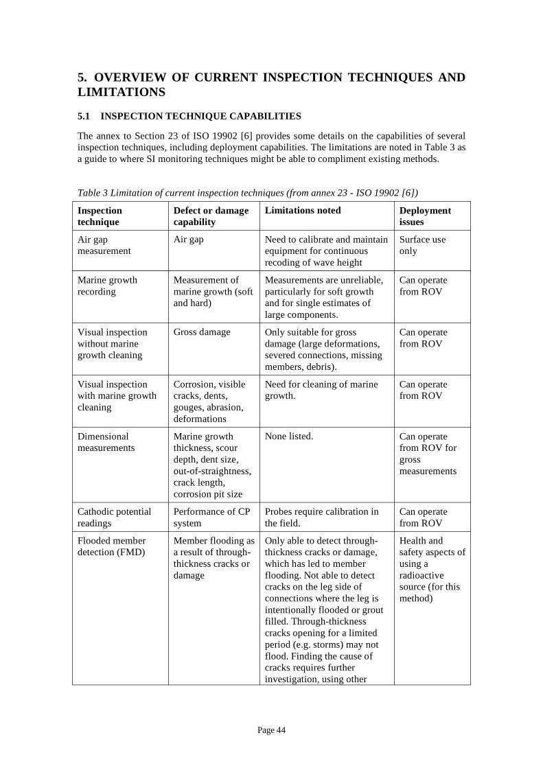
5. OVERVIEW OF CURRENT INSPECTION TECHNIQUES AND LIMITATIONS
5.1 INSPECTION TECHNIQUE CAPABILITIES
The annex to Section 23 of ISO 19902 [6] provides some details on the capabilities of several inspection techniques, including deployment capabilities. The limitations are noted in Table 3 as a guide to where SI monitoring techniques might be able to compliment existing methods.
Table 3 Limitation of current inspection techniques (from annex 23 - ISO 19902 [6])
Inspection Defect or damage Limitations noted Deployment technique capability issues
Air gap Air gap Need to calibrate and maintain Surface use measurement equipment for continuous only
recoding of wave height
Marine growth Measurement of Measurements are unreliable, Can operate recording marine growth (soft particularly for soft growth from ROV
and hard) and for single estimates of large components.
Visual inspection Gross damage Only suitable for gross Can operate without marine damage (large deformations, from ROV growth cleaning severed connections, missing
members, debris).
Visual inspection Corrosion, visible Need for cleaning of marine Can operate with marine growth cracks, dents, growth. from ROV cleaning gouges, abrasion,
deformations
Dimensional measurements
Marine growth thickness, scour
None listed. Can operate from ROV for
depth, dent size, gross out-of-straightness, crack length,
measurements
corrosion pit size
Cathodic potential readings
Performance of CP system
Probes require calibration in the field.
Can operate from ROV
Flooded member detection (FMD)
Member flooding as a result of through-
Only able to detect through-thickness cracks or damage,
Health and safety aspects of
thickness cracks or which has led to member using a damage flooding. Not able to detect
cracks on the leg side of radioactive source (for this
connections where the leg is method) intentionally flooded or grout filled. Through-thickness cracks opening for a limited period (e.g. storms) may not flood. Finding the cause of cracks requires further investigation, using other
Page 44
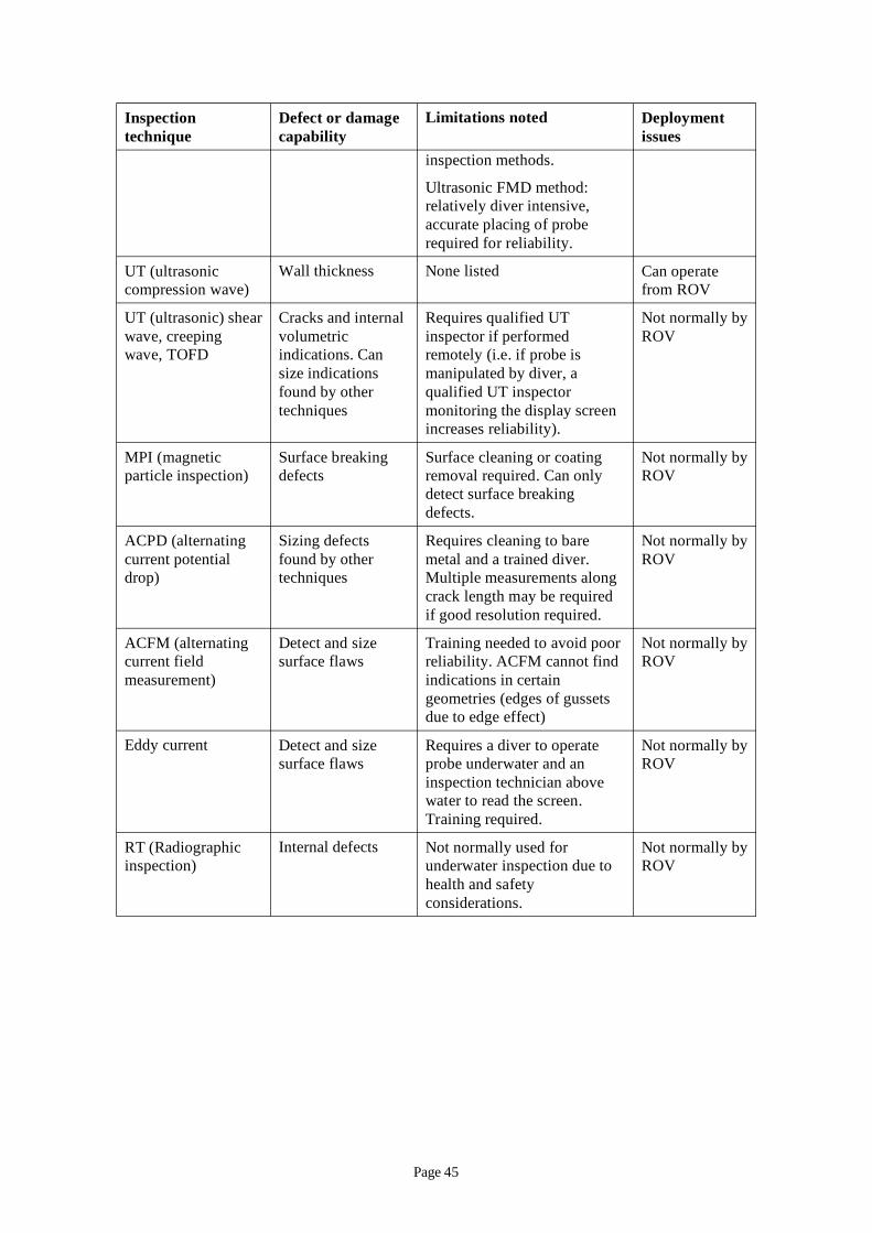
Inspection Defect or damage Limitations noted Deployment technique capability issues
inspection methods.
Ultrasonic FMD method: relatively diver intensive, accurate placing of probe required for reliability.
UT (ultrasonic Wall thickness None listed Can operate compression wave) from ROV
UT (ultrasonic) shear Cracks and internal Requires qualified UT Not normally by wave, creeping wave, TOFD
volumetric indications. Can
inspector if performed remotely (i.e. if probe is
ROV
size indications manipulated by diver, a found by other qualified UT inspector techniques monitoring the display screen
increases reliability).
MPI (magnetic Surface breaking Surface cleaning or coating Not normally by particle inspection) defects removal required. Can only ROV
detect surface breaking defects.
ACPD (alternating Sizing defects Requires cleaning to bare Not normally by current potential found by other metal and a trained diver. ROV drop) techniques Multiple measurements along
crack length may be required if good resolution required.
ACFM (alternating Detect and size Training needed to avoid poor Not normally by current field surface flaws reliability. ACFM cannot find ROV measurement) indications in certain
geometries (edges of gussets due to edge effect)
Eddy current Detect and size surface flaws
Requires a diver to operate probe underwater and an inspection technician above water to read the screen.
Not normally by ROV
Training required.
RT (Radiographic Internal defects Not normally used for Not normally by inspection) underwater inspection due to ROV
health and safety considerations.
Page 45
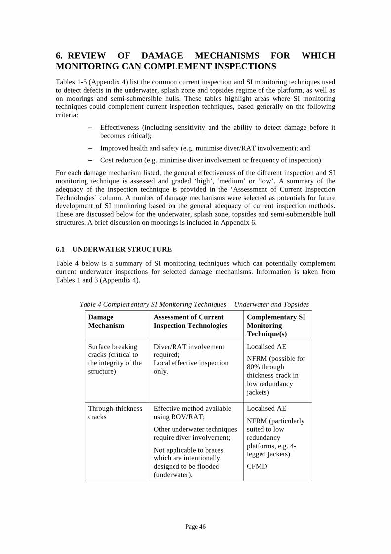
6. REVIEW OF DAMAGE MECHANISMS FOR WHICH MONITORING CAN COMPLEMENT INSPECTIONS Tables 1-5 (Appendix 4) list the common current inspection and SI monitoring techniques used to detect defects in the underwater, splash zone and topsides regime of the platform, as well as on moorings and semi-submersible hulls. These tables highlight areas where SI monitoring techniques could complement current inspection techniques, based generally on the following criteria:
– Effectiveness (including sensitivity and the ability to detect damage before it becomes critical);
– Improved health and safety (e.g. minimise diver/RAT involvement); and
– Cost reduction (e.g. minimise diver involvement or frequency of inspection).
For each damage mechanism listed, the general effectiveness of the different inspection and SI monitoring technique is assessed and graded ‘high’, ‘medium’ or ‘low’. A summary of the adequacy of the inspection technique is provided in the ‘Assessment of Current Inspection Technologies’ column. A number of damage mechanisms were selected as potentials for future development of SI monitoring based on the general adequacy of current inspection methods. These are discussed below for the underwater, splash zone, topsides and semi-submersible hull structures. A brief discussion on moorings is included in Appendix 6.
6.1 UNDERWATER STRUCTURE
Table 4 below is a summary of SI monitoring techniques which can potentially complement current underwater inspections for selected damage mechanisms. Information is taken from Tables 1 and 3 (Appendix 4).
Table 4 Complementary SI Monitoring Techniques – Underwater and Topsides
Damage Assessment of Current Complementary SI Mechanism Inspection Technologies Monitoring
Technique(s)
Surface breaking cracks (critical to the integrity of the structure)
Diver/RAT involvement required; Local effective inspection only.
Localised AE
NFRM (possible for 80% through thickness crack in low redundancy jackets)
Through-thickness cracks
Effective method available using ROV/RAT;
Other underwater techniques require diver involvement;
Not applicable to braces which are intentionally designed to be flooded (underwater).
Localised AE
NFRM (particularly suited to low redundancy platforms, e.g. 4-legged jackets)
CFMD
Page 46
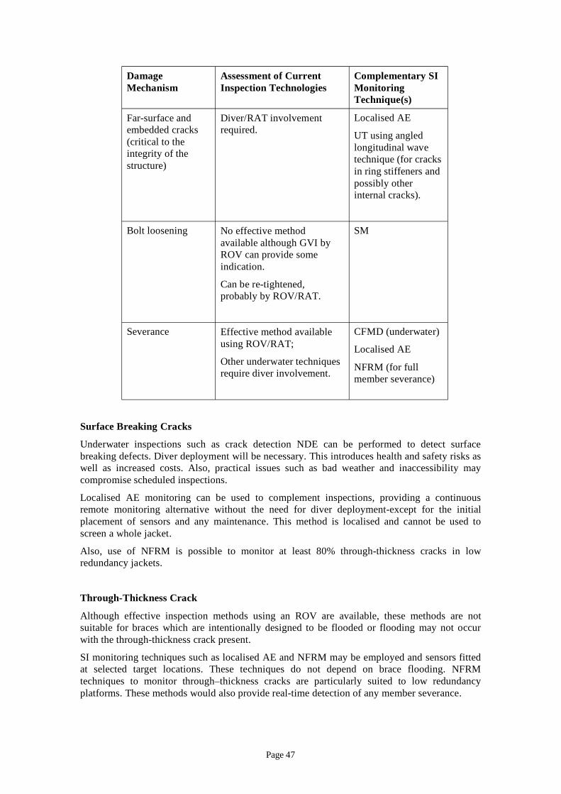
Damage Assessment of Current Complementary SI Mechanism Inspection Technologies Monitoring
Technique(s)
Far-surface and Diver/RAT involvement Localised AE embedded cracks (critical to the integrity of the structure)
required. UT using angled longitudinal wave technique (for cracks in ring stiffeners and possibly other internal cracks).
Bolt loosening No effective method available although GVI by ROV can provide some indication.
SM
Can be re-tightened, probably by ROV/RAT.
Severance Effective method available using ROV/RAT;
Other underwater techniques require diver involvement.
CFMD (underwater)
Localised AE
NFRM (for full member severance)
Surface Breaking Cracks
Underwater inspections such as crack detection NDE can be performed to detect surface breaking defects. Diver deployment will be necessary. This introduces health and safety risks as well as increased costs. Also, practical issues such as bad weather and inaccessibility may compromise scheduled inspections.
Localised AE monitoring can be used to complement inspections, providing a continuous remote monitoring alternative without the need for diver deployment-except for the initial placement of sensors and any maintenance. This method is localised and cannot be used to screen a whole jacket.
Also, use of NFRM is possible to monitor at least 80% through-thickness cracks in low redundancy jackets.
Through-Thickness Crack
Although effective inspection methods using an ROV are available, these methods are not suitable for braces which are intentionally designed to be flooded or flooding may not occur with the through-thickness crack present.
SI monitoring techniques such as localised AE and NFRM may be employed and sensors fitted at selected target locations. These techniques do not depend on brace flooding. NFRM techniques to monitor through–thickness cracks are particularly suited to low redundancy platforms. These methods would also provide real-time detection of any member severance.
Page 47
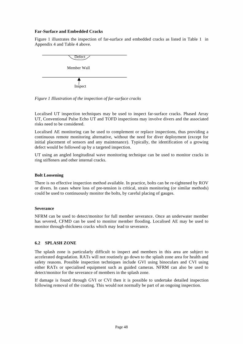
Far-Surface and Embedded Cracks
Figure 1 illustrates the inspection of far-surface and embedded cracks as listed in Table 1 in Appendix 4 and Table 4 above.
Defect
Member Wall
Inspect
Figure 1 Illustration of the inspection of far-surface cracks
Localised UT inspection techniques may be used to inspect far-surface cracks. Phased Array UT, Conventional Pulse Echo UT and TOFD inspections may involve divers and the associated risks need to be considered.
Localised AE monitoring can be used to complement or replace inspections, thus providing a continuous remote monitoring alternative, without the need for diver deployment (except for initial placement of sensors and any maintenance). Typically, the identification of a growing defect would be followed up by a targeted inspection.
UT using an angled longitudinal wave monitoring technique can be used to monitor cracks in ring stiffeners and other internal cracks.
Bolt Loosening
There is no effective inspection method available. In practice, bolts can be re-tightened by ROV or divers. In cases where loss of pre-tension is critical, strain monitoring (or similar methods) could be used to continuously monitor the bolts, by careful placing of gauges.
Severance
NFRM can be used to detect/monitor for full member severance. Once an underwater member has severed, CFMD can be used to monitor member flooding. Localised AE may be used to monitor through-thickness cracks which may lead to severance.
6.2 SPLASH ZONE
The splash zone is particularly difficult to inspect and members in this area are subject to accelerated degradation. RATs will not routinely go down to the splash zone area for health and safety reasons. Possible inspection techniques include GVI using binoculars and CVI using either RATs or specialised equipment such as guided cameras. NFRM can also be used to detect/monitor for the severance of members in the splash zone.
If damage is found through GVI or CVI then it is possible to undertake detailed inspection following removal of the coating. This would not normally be part of an ongoing inspection.
Page 48

6.3 TOPSIDES
Table 4 is a summary of SI monitoring techniques which can potentially complement current topsides inspections. The main driver for requiring monitoring is to replace the RAT requirement, which has an associated health and safety risk. It is also difficult to inspect effectively by rope access. It is not common to put in place a monitoring system on the topside structure as in general this can be inspected by conventional methods.
Corrosion
Corrosion is a significant problem for topside steelwork due to the exposure to marine environment. Corrosion under PFP/protective coating could be difficult to detect without coating removal.
Methods such as Long Range UT could be used to detect such corrosion, although the technique is still only at the development stage for many applications.
Severe local and general corrosion can be inspected effectively and at relatively low cost using methods such as Ultrasonic Wall Thickness techniques and CVI, without the need for SI monitoring (refer to Table 3 in Appendix 4).
6.4 SEMI-SUBMERSIBLE HULL STRUCTURE
This includes the inspection or monitoring of the subsea structure of a semi-submersible. It is important to note that defects in the structure leading to local breach of watertight integrity can be significant. Breach of watertight integrity may not lead to structural failure but may lead to loss of stability.
Table 4 (Appendix 4) which assesses the inspection and monitoring techniques for the underwater jacket structure shows that almost all the techniques are also relevant to semi-submersibles. However due to the different configurations, a number of the inspection/monitoring techniques are not relevant, and these are:
– Flooded member detection;
– Continuous flooded member detection;
– Natural frequency response monitoring; and
– Acoustic fingerprinting.
Leak Detection
LD is a particularly important technique for semi submersibles due to the need to detect any loss of watertight integrity at the early stages. There is also a requirement for LD in ageing semi-submersibles in Norway [12]. There are leak detection techniques already in use as discussed in Section 4.2.
Crack Monitoring
AE techniques are already in use to monitor crack growth internal to semi submersible structures and this is discussed in Section 4.1. Particularly for monitoring cracks in the hull structure, where through thickness cracking would lead to a breach of water tight integrity, AE has particular benefits as it can detect cracks before they extend through the thickness.
Page 49
7. OPPORTUNITIES FOR DEVELOPMENT OF SI MONITORING TECHNOLOGIES FOR LIFE EXTENSION
An increasing number of North Sea installations are reaching or have exceeded their original design lives and are either already into or are being considered for a life extension stage. This is because of the increased need to continue producing oil or gas or to act as a hub or host to nearby subsea completions.
Consideration of life extension requires knowledge of the relevant ageing mechanisms such as corrosion and fatigue, as well as having and maintaining a good understanding of the current state of the structure. This requires inspection and maintenance, for which SI monitoring technologies can play an important part.
One of the difficulties in obtaining knowledge of the current level of structural integrity is the lack of information on parts of the installation which are difficult to inspect by normal methods. These include welded pile sections, ring-stiffened joints and parts of the splash zone. This limit on knowledge of the structural integrity required for the life extension stage is significant and opportunities for application of SI monitoring technologies to these difficult to inspect items are important. Typical examples are described below:
1. Welded pile sections: these play an important part in maintaining the integrity of the foundation. The welded circumferential welds are difficult to inspect once installed. An additional problem is that some part of the welded connection’s original fatigue life will have been used up to an unknown extent during pile driving. Corrosion of steel is also a possibility in sections below ground where the CP system may be less effective.
2. Grouted connections: These are formed at the installation stage and therefore difficult to inspect at that stage and also in subsequent operational inspections.
3. Shear plates for pile-sleeve connectors: these form the main load path from the piles to the structure and are also difficult to inspect.
4. Ring-stiffened joints: Many platforms contain a number of ring stiffened joints. The stiffeners provide additional strength to resist static loading and can also assist in increasing fatigue life. The stiffeners are welded to the joint and can also contain welds within their own structure. Fatigue testing of such joints has shown that stiffeners do fail and this is not visible from the outside until major damage has occurred internally, significantly reducing the effectiveness of the joint. Cracks at the ring inner edge have been seen in fatigue tests; propagating to reduce the stiffness of the ring and the joint. This type of damage is also not visible externally in its initial stages.
5. Widespread fatigue damage: This type of damage has occurred in airframes and is a recognised problem for life extension of aircraft. Widespread fatigue damage (WFD) is defined as the simultaneous presence of cracks at multiple structural details that are of sufficient size and frequency such that the structure will no longer meet its damage tolerance requirement. There are two types of WFD:
1. Multiple site damage is characterised by the presence of multiple cracks in the same structural element, leading to a loss of the required residual strength.
2. Multiple element damage occurs where cracks occur in similar adjacent structural elements, again leading to a potential loss of residual strength.
Page 50
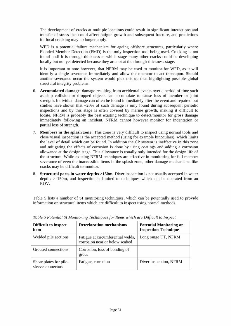
The development of cracks at multiple locations could result in significant interactions and transfer of stress that could affect fatigue growth and subsequent fracture, and predictions for local cracking may no longer apply.
WFD is a potential failure mechanism for ageing offshore structures, particularly where Flooded Member Detection (FMD) is the only inspection tool being used. Cracking is not found until it is through-thickness at which stage many other cracks could be developing locally but not yet detected because they are not at the through-thickness stage.
It is important to note however, that NFRM may be used to monitor for WFD, as it will identify a single severance immediately and allow the operator to act thereupon. Should another severance occur the system would pick this up thus highlighting possible global structural integrity problems.
6. Accumulated damage: damage resulting from accidental events over a period of time such as ship collision or dropped objects can accumulate to cause loss of member or joint strength. Individual damage can often be found immediately after the event and repaired but studies have shown that ~20% of such damage is only found during subsequent periodic inspections and by this stage is often covered by marine growth, making it difficult to locate. NFRM is probably the best existing technique to detect/monitor for gross damage immediately following an incident. NFRM cannot however monitor for indentation or partial loss of strength.
7. Members in the splash zone: This zone is very difficult to inspect using normal tools and close visual inspection is the accepted method (using for example binoculars), which limits the level of detail which can be found. In addition the CP system is ineffective in this zone and mitigating the effects of corrosion is done by using coatings and adding a corrosion allowance at the design stage. This allowance is usually only intended for the design life of the structure. While existing NFRM techniques are effective in monitoring for full member severance of even the inaccessible items in the splash zone, other damage mechanisms like cracks may be difficult to monitor.
8. Structural parts in water depths >150m: Diver inspection is not usually accepted in water depths > 150m, and inspection is limited to techniques which can be operated from an ROV.
Table 5 lists a number of SI monitoring techniques, which can be potentially used to provide information on structural items which are difficult to inspect using normal methods.
Table 5 Potential SI Monitoring Techniques for Items which are Difficult to Inspect
Difficult to inspect item
Deterioration mechanisms Potential Monitoring or Inspection Technique
Welded pile sections Fatigue at circumferential welds, corrosion near or below seabed
Long range UT, NFRM
Grouted connections Corrosion, loss of bonding of grout
Shear plates for pile-sleeve connectors
Fatigue, corrosion Diver inspection, NFRM
Page 51
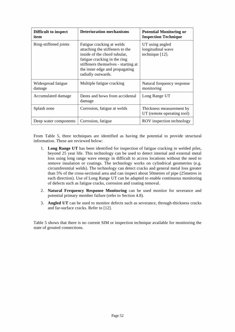
Difficult to inspect Deterioration mechanisms Potential Monitoring or item Inspection Technique
Ring-stiffened joints Fatigue cracking at welds attaching the stiffeners to the
UT using angled longitudinal wave
inside of the chord tubular, technique [12]. fatigue cracking in the ring stiffeners themselves - starting at the inner edge and propagating radially outwards.
Widespread fatigue Multiple fatigue cracking Natural frequency response damage monitoring
Accumulated damage Dents and bows from accidental Long Range UT damage
Splash zone Corrosion, fatigue at welds Thickness measurement by UT (remote operating tool)
Deep water components Corrosion, fatigue ROV inspection technology
From Table 5, three techniques are identified as having the potential to provide structural information. These are reviewed below:
1. Long Range UT has been identified for inspection of fatigue cracking in welded piles, beyond 25 year life. This technology can be used to detect internal and external metal loss using long range wave energy in difficult to access locations without the need to remove insulation or coatings. The technology works on cylindrical geometries (e.g. circumferential welds). The technology can detect cracks and general metal loss greater than 5% of the cross-sectional area and can inspect about 50metres of pipe (25metres in each direction). Use of Long Range UT can be adapted to enable continuous monitoring of defects such as fatigue cracks, corrosion and coating removal.
2. Natural Frequency Response Monitoring can be used monitor for severance and potential primary member failure (refer to Section 4.8).
3. Angled UT can be used to monitor defects such as severance, through-thickness cracks and far-surface cracks. Refer to [12].
Table 5 shows that there is no current SIM or inspection technique available for monitoring the state of grouted connections.
Page 52
8. REQUIREMENTS FOR DEVELOPMENT OF SI MONITORINGTECHNIQUES
This review has shown that existing SI monitoring techniques have several limitations in respect of the need for offshore deployment and other factors. These are described in Section 4. Some development work is already underway with the equipment suppliers. However it is felt useful to list potential developments which could improve the capability of SI monitoring methods to complement existing inspection techniques. These are:
– ROV deployment: Section 4.1 describes the need for diver deployment as a significant limitation (for AE monitoring) recognising the costs of operating a diving support vessel and the health and safety hazards which may arise from having divers in the water. A particular need is to be able to attach sensors or gauges and associated equipment underwater using a ROV.
– Replacement of RAT requirement: rope access is a recognised method of access to the splash zone and parts of the topside structure to use inspection techniques, such as UT for thickness monitoring. There is a health and safety risk associated with this method. It may also be difficult to inspect effectively by rope access. Alternative methods which do not require rope access would be beneficial.
– Cabling through the water and splash zone: the transmission of signals from underwater sensors to the topside is a requirement in many cases. Cabling is vulnerable to damage caused by wave action or dropped objects. Some progress has been made with through-water telemetry or transmission of signals through the structure but further work would be beneficial.
– Need for experienced and qualified operating personnel: some SI monitoring techniques require interpretation of the output by qualified and experienced operators. A particular example is acoustic emissions monitoring where it is known that data can be difficult to interpret and the raw data needs to be processed by specialist software which is usually owned by the supplier of the system. External accreditation of these methods would be useful and lead to more confidence in the results.
– Extended battery life: one of the listed limitations of external CFMD is the limited life of current battery systems (i.e. 10 years maximum). Battery replacement by ROV or longer life batteries would enable this technique to have wider applicability.
– Reduction of background noise: background noise from wave action or from equipment on the installation limits the sensitivity of some SI monitoring methods. For example the ability of NFRM to detect smaller defects is limited by background noise. Improved methods of filtering or noise cancellation could lead to higher sensitivities. An acoustic emissions system can be prone to background noise which can affect its accuracy and reduce the probability of detection.
– Robust sensors: deployment of sensors underwater can lead to damage from wave action or other mechanisms. Replacement of sensors can be difficult and costly. The development of more robust sensors and attachments would be beneficial for these applications.
– Development of existing methods: Section 4 shows some limitations of existing SI monitoring methods. Improvement of the methods to overcome these limitations would be beneficial. An example is leak detection which is a
Page 53

particularly important technique because of the need to maintain watertight integrity in semi-submersibles.
– Wider applicability of current SI monitoring methods: an example is long range UT which has been demonstrated for inspection for corrosion on pipework over long distances. It is seen as a potential method for inspecting welded piles which are difficult to inspect using existing methods; however, long range UT would need to be demonstrated for this particular application through a test programme.
– Development of new methods: the report notes that no existing SI monitoring or inspection method is available for detection of damage in grouted connections or in shear plates for pile-sleeve connectors (both relevant to life extension). There is an opportunity for new techniques to be developed.
Page 54

9. CONCLUSIONS On the basis of the review presented in this report, the following conclusions have been made:
1. A review of relevant codes and standards has been carried out. While there are a number of codes and standards which make reference to SI monitoring, no standard on its application in the offshore industry exists.
2. A significant number of SI monitoring techniques exist and these have been reviewed. A number of SI monitoring methods have been well developed and are available for monitoring of integrity related parameters without the requirement for significant further development. These include:
– Acoustic emissions monitoring;
– Air gap monitoring;
– GPS monitoring;
– Leak detection;
– Natural frequency response monitoring;
– Strain monitoring; and
– Riser and anchor chain monitoring.
3. With the increasing need to demonstrate that structural integrity risks are managed and as low as reasonably practicable, the need to consider structural monitoring as part of the platform safety case is anticipated to increase in the future and these mature technologies would be prime candidates.
4. Methods which would require further development before they would become practicable as widely applied SI monitoring methods include:
– Acoustic fingerprinting
– Continuous flooded member detection (external/internal)
– Fatigue gauge monitoring
5. A qualitative assessment has been carried out to identify where SI monitoring can complement periodic inspection methods. Damage mechanisms for which SI monitoring techniques can complement inspection methods include:
– Surface-breaking cracks – localised acoustic emissions monitoring, natural frequency response monitoring (80% through-thickness cracks);
– Through-thickness cracks – localised acoustic emissions monitoring, natural frequency response monitoring, leak detection;
– Far-surface and embedded cracks – localised acoustic emissions;
– Full-member severance – natural frequency response monitoring;
– Loss of mooring line tension – anchor chain monitoring: suitable for long term deployment; sonar rays continuously scan the global mooring arrangement monitoring mooring presence and positioning.
6. The special inspection requirements for demonstrating life extension in ageing installations have been addressed. SI monitoring techniques can be used to detect damage mechanisms on difficult to inspect items. These include:
– Welded pile sections;
Page 55

– Ring-stiffened joints and items in the splash zone; and
– Deep water components.
Potential SI monitoring techniques for these items include long range UT, UT using angled probes, NFRM and thickness measurement using UT with a remote probe.
7. Further development of existing SI monitoring techniques is required to meet offshore requirements and some examples are given of potentially useful developments.
Page 56

10. REFERENCES [1] “The Offshore Installations and Wells (Design and Construction etc.) Regulations”, SI
1996/913, HMSO, 1996.
[2] HSE Information Sheet, “Reducing the Risks Associated with Flooded Machinery Spaces on Monohull FPSO and FSU Installations”, Offshore Information Sheet 8/2007, 2007.
[3] Det Norsk Veritas, OSS-101, “Rules for Classification of Offshore Drilling and Support Units, Special Provisions for Ageing Mobile Offshore and Self-Elevating Structures”, 2007.
[4] American Petroleum Institute, “Offshore Structures Design Practice”, API RP 2A, 21st edition, 2000.
[5] DEN, “Department of Energy Guidance Note”, 1990.
[6] International Standards Organisation, “Petroleum & Natural Gas Industries – Offshore Structures, Fixed Offshore Structures”, ISO 19902, 2007.
[7] NORSOK, “Condition Monitoring of Load Bearing Structures, N-005”, 1997.
[8] International Standards Organisation, “Performance Parameters for Condition Monitoring of Structures”, ISO 16587, 2004.
[9] International Standards Organisation, Petroleum and Natural Gas Industries - Specific Requirements for Offshore Structures, ISO19901 Part 3: “Topsides structure”, 2005.
[10] American Petroleum Institute, “Recommended Practice for the Structural Integrity Management of Fixed Offshore Structures (Draft)”, 2007.
[11] HSE, “Cost Effective Structural Monitoring – An Acoustic Method, Phase II”, Research Report 325, Prepared by Mecon Limited for the HSE, 2005.
[12] J.V. Sharp (Cranfield University), A. Stacey (Offshore Safety Division, HSE), “Application of Structural Integrity Monitoring to Life Extension of Ageing Offshore Installations”, Major Hazards Offshore & Onshore 2004 ERA conference, Leatherhead, Dec 2004.
[13] James W. Dally, William F. Riley, “Experimental Stress Monitoring”, 2005.
[14] Stephen Williams, “’Chain Test’ – Automated Inspection of Mooring Chains”, TWI Collaborative Research Knowledge Summary, http://www.twi.co.uk/j32k/protected/band_3/crks1.html, 2007.
Page 57

APPENDIX 1
Review of SI Monitoring published reports and documents
Page 58
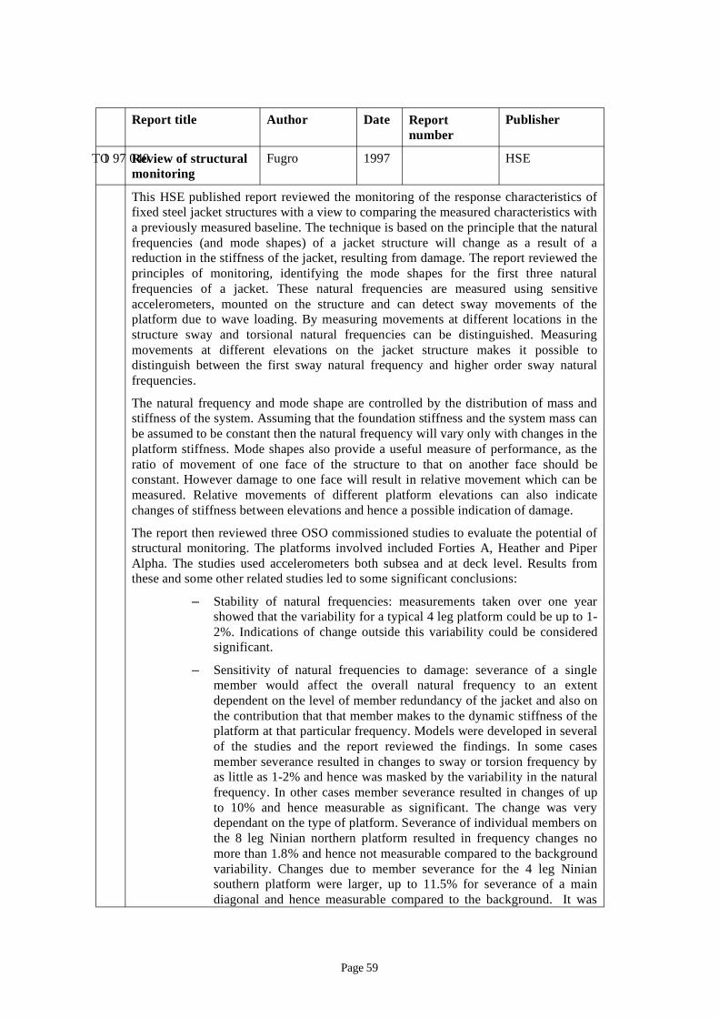
OTO 97 040
Report title Author Date Report number
Publisher
1 Review of structural monitoring
Fugro 1997 HSE
This HSE published report reviewed the monitoring of the response characteristics of fixed steel jacket structures with a view to comparing the measured characteristics with a previously measured baseline. The technique is based on the principle that the natural frequencies (and mode shapes) of a jacket structure will change as a result of a reduction in the stiffness of the jacket, resulting from damage. The report reviewed the principles of monitoring, identifying the mode shapes for the first three natural frequencies of a jacket. These natural frequencies are measured using sensitive accelerometers, mounted on the structure and can detect sway movements of the platform due to wave loading. By measuring movements at different locations in the structure sway and torsional natural frequencies can be distinguished. Measuring movements at different elevations on the jacket structure makes it possible to distinguish between the first sway natural frequency and higher order sway natural frequencies.
The natural frequency and mode shape are controlled by the distribution of mass and stiffness of the system. Assuming that the foundation stiffness and the system mass can be assumed to be constant then the natural frequency will vary only with changes in the platform stiffness. Mode shapes also provide a useful measure of performance, as the ratio of movement of one face of the structure to that on another face should be constant. However damage to one face will result in relative movement which can be measured. Relative movements of different platform elevations can also indicate changes of stiffness between elevations and hence a possible indication of damage.
The report then reviewed three OSO commissioned studies to evaluate the potential of structural monitoring. The platforms involved included Forties A, Heather and Piper Alpha. The studies used accelerometers both subsea and at deck level. Results from these and some other related studies led to some significant conclusions:
– Stability of natural frequencies: measurements taken over one year showed that the variability for a typical 4 leg platform could be up to 1-2%. Indications of change outside this variability could be considered significant.
– Sensitivity of natural frequencies to damage: severance of a single member would affect the overall natural frequency to an extent dependent on the level of member redundancy of the jacket and also on the contribution that that member makes to the dynamic stiffness of the platform at that particular frequency. Models were developed in several of the studies and the report reviewed the findings. In some cases member severance resulted in changes to sway or torsion frequency by as little as 1-2% and hence was masked by the variability in the natural frequency. In other cases member severance resulted in changes of up to 10% and hence measurable as significant. The change was very dependant on the type of platform. Severance of individual members on the 8 leg Ninian northern platform resulted in frequency changes no more than 1.8% and hence not measurable compared to the background variability. Changes due to member severance for the 4 leg Ninian southern platform were larger, up to 11.5% for severance of a main diagonal and hence measurable compared to the background. It was
Page 59
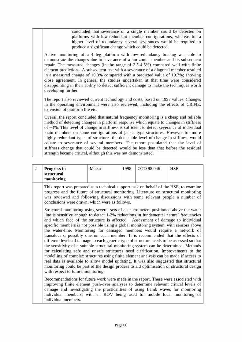
-
-re
- )
;
j
concluded that severance of a single member could be detected on platforms with low redundant member configurations, whereas for a higher level of redundancy several severances would be required to produce a significant change which could be detected.
Active monitoring of a 4 leg platform with low dundancy bracing was able to demonstrate the changes due to severance of a horizontal member and its subsequent repair. The measured changes (in the range of 2.5 4.5% compared well with finite element predictions. A subsequent test with a severance of a diagonal member resulted in a measured change of 10.3% compared with a predicted value of 10.7% showing close agreement. In general the studies undertaken at that time were considered disappointing in their ability to detect sufficient damage to make the techniques worth developing further.
The report also reviewed current technology and costs, based on 1997 values. Changes in the operating environment were also reviewed, including the effects of CRINE, extension of platform life etc.
Overall the report concluded that natural frequency monitoring is a cheap and reliable method of detecting changes in platform response which equate to changes in stiffness of ~3%. This level of change in stiffness is sufficient to detect severance of individual main members on some configurations of acket type structures. However for more highly redundant types of structures the detectable level of change in stiffness would equate to severance of several members. The report postulated that the level of stiffness change that could be detected would be less than that before the residual strength became critical, although this was not demonstrated.
2 Progress in structural monitoring
Matsu 1998 OTO 98 046 HSE
This report was prepared as a technical support task on behalf of the HSE, to examine progress and the future of structural monitoring. Literature on structural monitoring was reviewed and following discussions with some relevant people a number of conclusions were drawn, which were as follows.
Structural monitoring using several sets of accelerometers positioned above the water line is sensitive enough to detect 1-2% reductions in fundamental natural frequencies and which face of the structure is affected. Assessment of damage to individual specific members is not possible using a global monitoring system, with sensors above the water-line. Monitoring for damaged members would require a network of transducers, possibly one on each member. It is recommended that the effects of different levels of damage to each generic type of structure needs to be assessed so that the sensitivity of a suitable structural monitoring system can be determined. Methods for calculating safe and unsafe structures need clarification. Improvements to the modelling of complex structures using finite element analysis can be made if access to real data is available to allow model updating. It was also suggested that structural monitoring could be part of the design process to aid optimisation of structural design with respect to future monitoring.
Recommendations for future work were made in the report. These were associated with improving finite element push-over analyses to determine relevant critical levels of damage and investigating the practicalities of using Lamb waves for monitoring individual members, with an ROV being used for mobile local monitoring of individual members.
Page 60
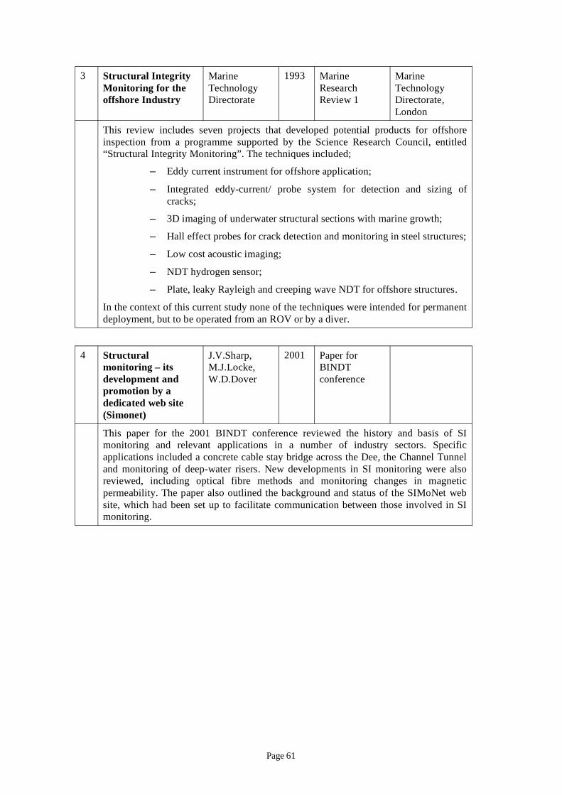
3 Structural Integrity Monitoring for the offshore Industry
Marine Technology Directorate
1993 Marine Research Review 1
Marine Technology Directorate, London
This review includes seven projects that developed potential products for offshore inspection from a programme supported by the Science Research Council, entitled “Structural Integrity Monitoring”. The techniques included;
– Eddy current instrument for offshore application;
– Integrated eddy-current/ probe system for detection and sizing of cracks;
– 3D imaging of underwater structural sections with marine growth;
– Hall effect probes for crack detection and monitoring in steel structures;
– Low cost acoustic imaging;
– NDT hydrogen sensor;
– Plate, leaky Rayleigh and creeping wave NDT for offshore structures.
In the context of this current study none of the techniques were intended for permanent deployment, but to be operated from an ROV or by a diver.
4 Structural monitoring – its development and promotion by a dedicated web site (Simonet)
J.V.Sharp, M.J.Locke, W.D.Dover
2001 Paper for BINDT conference
This paper for the 2001 BINDT conference reviewed the history and basis of SI monitoring and relevant applications in a number of industry sectors. Specific applications included a concrete cable stay bridge across the Dee, the Channel Tunnel and monitoring of deep-water risers. New developments in SI monitoring were also reviewed, including optical fibre methods and monitoring changes in magnetic permeability. The paper also outlined the background and status of the SIMoNet web site, which had been set up to facilitate communication between those involved in SI monitoring.
Page 61

5 Cost effective structural monitoring
Mecon Ltd 2001 OTO 2000 092 HSE
This report described the results of a test programme, using a new method for detecting damage in jacket structures. The method is aimed at detecting and locating significant changes in the structural properties of a jacket type structure e.g. a crack at a joint), via the changes they would cause in elastic wave propagation through the structure. Demonstration work was carried out in air on a small scale 2D cross braced frame made from a well damped material. The frame had two main legs with three cross members and was instrumented at each node. One end of one of the cross members was progressively cut to simulate a crack. The response at every node to excitation at one extreme of the frame was analysed, together with its impact on the identification of cracks in a larger structure. The results obtained showed some evidence that increasing damage (in the shape of progressive cutting) could be seen at the relevant locations. It was concluded that for a full scale rig it might be possible to use roughly one sensor per ten members with excitation at the top of each vertical leg. However although the results showed some promise the model was very simple and the application of the technique to a real steel structure required significant further work (see later reports).
6 Cost effective structural monitoring – an acoustic method, Phase II
Mecon Ltd 2005 Research Report 325
HSE
This report describes the results from the second phase of the HSE funded study and includes details of the numerical simulations and of physical experiments on the scale model. The plastic model involved was a 1/100 scale of the Claymore platform. The report claims that the numerical simulations were sound in principle. In the experiments a set of acoustic sources were placed at the top of the structure to transmit signals to a set of receivers at the bottom. However it was recognised that it would be better to have both transmitters and receivers at the top of the structure for practical reasons. It is also claimed that numerical simulations of this arrangement provided better results than the previous arrangement. Further work was planned to test this arrangement in practice.
Page 62
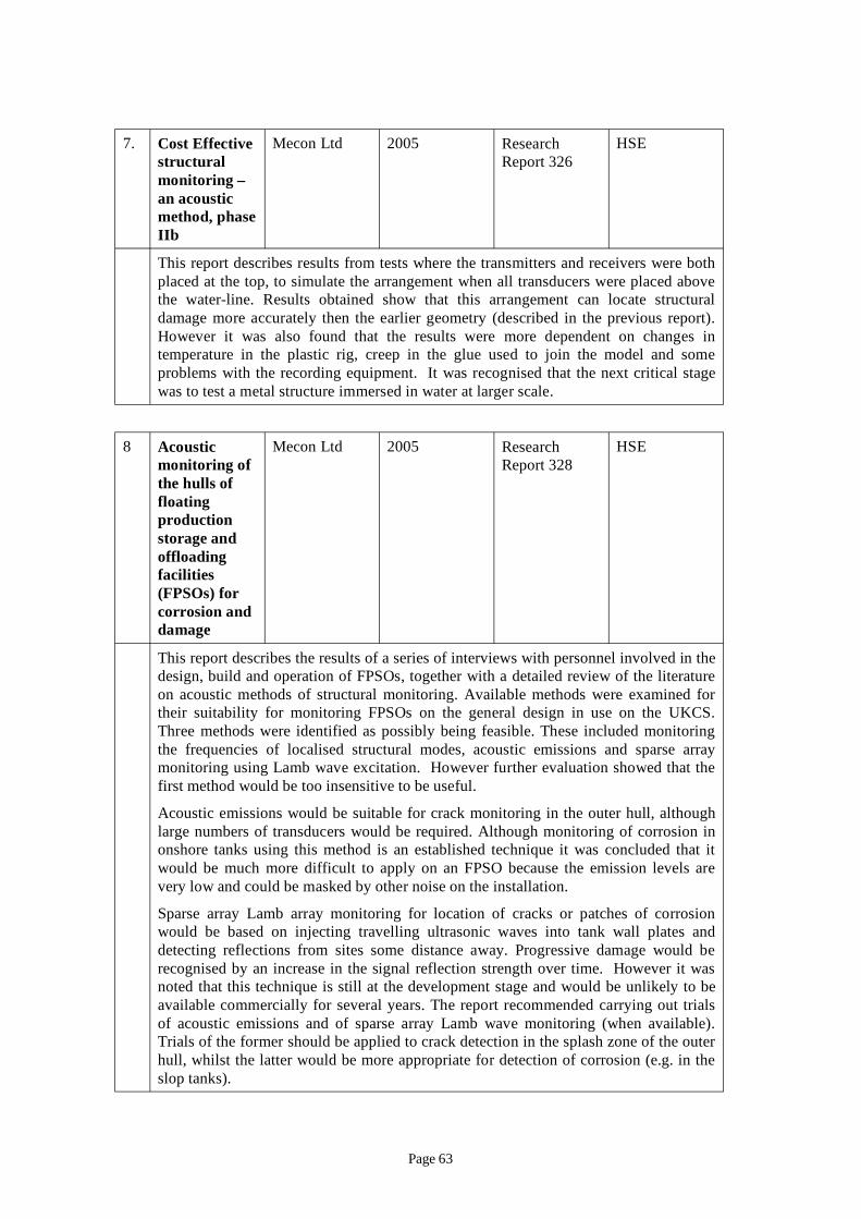
7. Cost Effective structural monitoring – an acoustic method, phase IIb
Mecon Ltd 2005 Research Report 326
HSE
This report describes results from tests where the transmitters and receivers were both placed at the top, to simulate the arrangement when all transducers were placed above the water-line. Results obtained show that this arrangement can locate structural damage more accurately then the earlier geometry (described in the previous report). However it was also found that the results were more dependent on changes in temperature in the plastic rig, creep in the glue used to join the model and some problems with the recording equipment. It was recognised that the next critical stage was to test a metal structure immersed in water at larger scale.
8 Acoustic monitoring of the hulls of floating production storage and offloading facilities (FPSOs) for corrosion and damage
Mecon Ltd 2005 Research Report 328
HSE
This report describes the results of a series of interviews with personnel involved in the design, build and operation of FPSOs, together with a detailed review of the literature on acoustic methods of structural monitoring. Available methods were examined for their suitability for monitoring FPSOs on the general design in use on the UKCS. Three methods were identified as possibly being feasible. These included monitoring the frequencies of localised structural modes, acoustic emissions and sparse array monitoring using Lamb wave excitation. However further evaluation showed that the first method would be too insensitive to be useful.
Acoustic emissions would be suitable for crack monitoring in the outer hull, although large numbers of transducers would be required. Although monitoring of corrosion in onshore tanks using this method is an established technique it was concluded that it would be much more difficult to apply on an FPSO because the emission levels are very low and could be masked by other noise on the installation.
Sparse array Lamb array monitoring for location of cracks or patches of corrosion would be based on injecting travelling ultrasonic waves into tank wall plates and detecting reflections from sites some distance away. Progressive damage would be recognised by an increase in the signal reflection strength over time. However it was noted that this technique is still at the development stage and would be unlikely to be available commercially for several years. The report recommended carrying out trials of acoustic emissions and of sparse array Lamb wave monitoring (when available). Trials of the former should be applied to crack detection in the splash zone of the outer hull, whilst the latter would be more appropriate for detection of corrosion (e.g. in the slop tanks).
Page 63
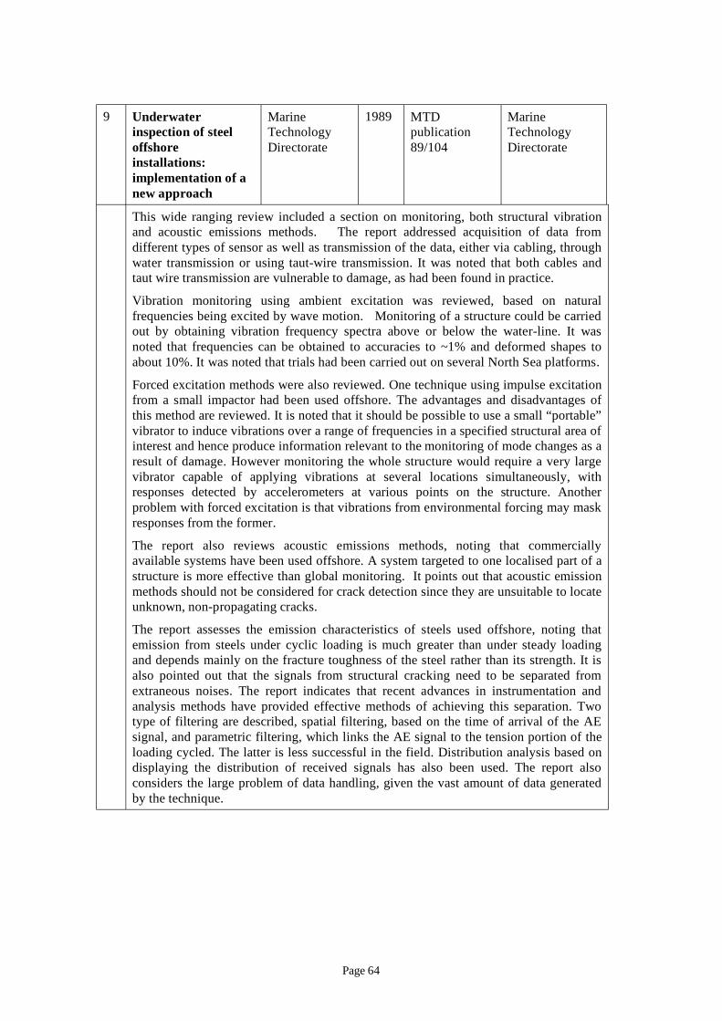
9 Underwater inspection of steel offshore installations: implementation of a new approach
Marine Technology Directorate
1989 MTD publication 89/104
Marine Technology Directorate
This wide ranging review included a section on monitoring, both structural vibration and acoustic emissions methods. The report addressed acquisition of data from different types of sensor as well as transmission of the data, either via cabling, through water transmission or using taut-wire transmission. It was noted that both cables and taut wire transmission are vulnerable to damage, as had been found in practice.
Vibration monitoring using ambient excitation was reviewed, based on natural frequencies being excited by wave motion. Monitoring of a structure could be carried out by obtaining vibration frequency spectra above or below the water-line. It was noted that frequencies can be obtained to accuracies to ~1% and deformed shapes to about 10%. It was noted that trials had been carried out on several North Sea platforms.
Forced excitation methods were also reviewed. One technique using impulse excitation from a small impactor had been used offshore. The advantages and disadvantages of this method are reviewed. It is noted that it should be possible to use a small “portable” vibrator to induce vibrations over a range of frequencies in a specified structural area of interest and hence produce information relevant to the monitoring of mode changes as a result of damage. However monitoring the whole structure would require a very large vibrator capable of applying vibrations at several locations simultaneously, with responses detected by accelerometers at various points on the structure. Another problem with forced excitation is that vibrations from environmental forcing may mask responses from the former.
The report also reviews acoustic emissions methods, noting that commercially available systems have been used offshore. A system targeted to one localised part of a structure is more effective than global monitoring. It points out that acoustic emission methods should not be considered for crack detection since they are unsuitable to locate unknown, non-propagating cracks.
The report assesses the emission characteristics of steels used offshore, noting that emission from steels under cyclic loading is much greater than under steady loading and depends mainly on the fracture toughness of the steel rather than its strength. It is also pointed out that the signals from structural cracking need to be separated from extraneous noises. The report indicates that recent advances in instrumentation and analysis methods have provided effective methods of achieving this separation. Two type of filtering are described, spatial filtering, based on the time of arrival of the AE signal, and parametric filtering, which links the AE signal to the tension portion of the loading cycled. The latter is less successful in the field. Distribution analysis based on displaying the distribution of received signals has also been used. The report also considers the large problem of data handling, given the vast amount of data generated by the technique.
Page 64
10 Crack detection by acoustic emissions
L.M.Rogers, Lloyds Register Marine Division
1998 Journal of Offshore Technology
This paper describes the acoustic emissions technique, the source of the emissions and the likely propagation distance in steel structures. The report also describes the use of acoustic emissions techniques as a supplementary method for monitoring fatigue cracks in large welded tubular joints as part of the UK Offshore Steels Research Programme undertaken in the 1970-80’s. This work showed that the acoustic emissions behaviour changed with the crack growth rate, enabling an estimate to be made of the crack depth from the character of the acoustic emissions signal.
The report also highlighted a case study which involved monitoring crack growth on a nodal joint below water. A general visual survey had shown that a horizontal brace at an elevation of –43m was severed. Failure had occurred at one end of an access window in the brace, due to a root weld defect. Detailed inspection of other access windows indicated a large number of similar defects, of which ten were repaired using saturation diving. Fracture mechanics analysis methods showed that the remaining windows had adequate fatigue life. A later analysis predicted fatigue lives as short as five years for one particular access window. To avoid an expensive repair acoustic emissions transducers were attached around the window to monitor the crack growth. The sensors were installed by divers using the taut wire method to relay signals back to the surface. Monitoring of the crack was undertaken over two winters, with claimed accurate location of the defects present. The length and approximate depth of each indication was found to agree with available NDT data. More significantly there was no evidence of significant crack growth which would require repair.
The paper notes that applications of acoustic emissions monitoring on offshore installations has been limited to known cracked nodes and other similar areas at that time.
11 Progress in acoustic emission monitoring of offshore installations
L.M.Rogers, Subsea Offshore Ltd
1994 6th European conference on Non-destructive testing
This paper reviews the application of acoustic emission monitoring to fatigue crack detection in offshore steel jacket structures. It provides results from monitoring a known crack in a nodal joint below water during the winter of 1993/94. An array of sensors was used with a spacing of up top 2m. This enabled the surface length of the active crack front to be defined with an accuracy of between 20-40mm. A brace to chord joint was detected as acoustically active using 3 sensors of a larger array used to monitor this node. The paper describes the results from one year’s monitoring to illustrate the reliability of the crack location and sizing capability. As a result of the monitoring it was concluded that the defect did not pose an immediate threat to the integrity of the joint. Decisions to delay repairing the defect resulted in significant reduced maintenance costs.
Page 65
12 Monitoring structural integrity of North Sea production platforms by acoustic emission
J.S.Mitchell (Chevron (UK) Ltd)& L.M.Rogers (Subsea Offshore Ltd)
1992 OTC Conference, Houston 1992
OTC Conference proceedings, Paper OTC 6957
This paper describes the background to the use of acoustic emission (AE) monitoring of North Sea platforms and the application of the method to the monitoring of subsea welds in the Ninian South platform. This monitoring was fully automated and initially used a taut-wire system to relay signals to the platform and to a modem for data transfer to shore. The decision to use AE monitoring was taken following the severance of a horizontal brace as a result of a fatigue crack growing at one end of an access window. Detailed NDE inspection of other access windows had shown a large number of similar defects of various sizes. Several were repaired using saturation diving. It was decided to monitor some of the remaining ones by using conventional NDE methods, such as ultrasonics. One particular remaining defect had a predicted remaining life of only 5 years and it was decided to monitor this using AE methods.
It was found that measured defect sizes from the AE results were in good agreement with previous data from other NDE methods. Over the three year monitoring period defect growth was found to be minimal and it was concluded that a repair was not necessary at that stage.
The paper also describes the development of a miniaturised AE sensor capable of remote operation, which was trialled on the Ninian platform with some limited success. It was intended to operate the sensor without any wires to the surface, using subsea data storage, but at the stage of preparing the paper this development had not been completed.
Page 66
13 Structural and Engineering monitoring by acoustic emission – fundamentals and applications
L.M.Rogers (Lloyds Register)
2001 Lloyds report
This detailed report outlines the fundamentals of the acoustic emission effect, associated with degradation mechanisms such as fatigue and stress corrosion in both steels and aluminium alloys. The microstructure of fatigue cracks and the different magnitude AE event associated with different stages of the crack growth are reviewed. Expressions are given for the critical plastic zone sizes and the wave displacement amplitudes produced by a sub-surface micro-crack, together with details of how stress waves propagate through the structure.
A methodology is described for correcting the measured signal amplitude for attenuation in the structure. Case studies are also presented to demonstrate the application of this technique to several different types of structure, including nodal joints in offshore structures, testing of an aircraft wing panel, stress corrosion cracking of a steel pressure vessel, re-qualification of high pressure gas cylinders and condition monitoring of heavily loaded bearings.
14 Network for structural monitoring
J.V.Sharp and W.D.Dover
2003 Materials World
Vol. 11, No.6, P.34 June 2003
This paper describes the background to the setting up of the SIMoNet SI monitoring network and web site. Background is provided on the importance of structural integrity and costs of maintenance. Life extension is an upcoming issue in which SI monitoring plays an important part. The network aims to bring together those involved in SI monitoring across a wide range of disciplines and applications. Workshops are held regularly with particular themes. The network also provides information on new and developing techniques for SI monitoring. The cross-industry nature of the network has advantages in enabling members to see where new technologies are being applied and whether these might be relevant to their own field.
Page 67
15 Non-destructive evaluation of wire ropes – utilising acoustic emission techniques
G.R.Drummond, J.F.Taylor, R.M.Taylor, Robert Gordon University
This paper describes laboratory test on five wire ropes with induced flaws of known severity and monitored for acoustic emission. It was found possible to monitor the condition of the wire rope and diagnose the severity of the damage that had been induced. It was shown that there was a reasonably linear relationship between the sum of the acoustic energy emitted during the application of a proof load to the reduction in cross-sectional area due to the induced defect. However application of a “safe working load (SWL)” did not provide this level of demonstration, because the SWL is a smaller fraction of the load required to break an unflawed rope. It was claimed that it could be feasible for this method to provide a method on monitoring wire ropes non-destructively in situ, although there was a considerable amount of further work required to demonstrate this.
16 Condition monitoring techniques for fibre mooring ropes
G.Rebel, C.R.Chaplin, C. Groives-Kirkby, I.M.L.Ridge (Reading University)
The long-term integrity of polyester fibre mooring lines, being used to moor floating oil production platforms in deep-water is an increasing problem, as none of the NDE methods developed for steel wire mooring ropes are relevant. The paper describes the possible approaches which have been considered elsewhere for the condition monitoring of fibre ropes. It was decided that the most promising technique is the use of distributed fibre optic sensors, particularly those using multiple Bragg reflection gratings.
One of the main problems is the difference in failure strains between the fibres and the mooring lines (1% c.f. 10-15%). The paper also points out other concerns such as the required resolution for the system, the need for ruggedness of the optical fibre within the fibre rope and the failure behaviour of the combined optical/polyester rope.
Page 68
17 Report title Author Date Report number
Publisher
Application of A.Stacey Dec. Conference ERA structural integrity (Offshore Safety 2004 report, Conference, monitoring to life Division, HSE) published by London. extension of ageing offshore installations
J.V.Sharp (Cranfield University)
ERA Technology, Leatherhead
“Major Hazards Offshore & Onshore 2004”
This conference paper identified the reasons for life extension and the information required for reassessment to support a case for life extension. The assessment process was based on the steps listed in ISO 19902, which include condition assessment. The inspection programmes required for this step were reviewed and limitations identified.
SI monitoring techniques were reviewed and the potential for these to complement existing inspection methods assessed. Acoustic emission and vibration monitoring methods were seen as the most promising methods for use in life extension assessment.
Page 69

APPENDIX 2
Comparison of Characteristics of Structural Monitoring Methods
Page 70
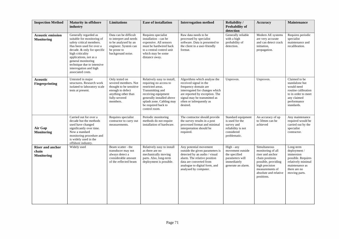
Inspection Method Maturity in offshore Limitations Ease of installation Interrogation method Reliability / Accuracy Maintenance industry Probability of
detection Acoustic emission Generally regarded as Data can be difficult Requires specialist Raw data needs to be Generally reliable Modern AE systems Requires periodic Monitoring suitable for monitoring of
safety critical members. Has been used for over a
to interpret and needs to be analysed by an engineer. System can
installation - can be expensive. All sensors must be hardwired back
processed by specialist software. Data is presented to the client in a user-friendly
with a high probability of detection.
are very accurate and can detect crack initiation,
specialist maintenance and recalibration.
decade. & only for specific high criticality applications, not as a
be prone to background noise.
to a central control unit which may be some distance away.
format. propagation.
general monitoring technique due to intensive interrogation and high associated costs.
Acoustic Fingerprinting
Untested in major structures. Research work isolated to laboratory scale tests at present.
Only tested on severed members. Not thought to be sensitive enough to defect anything other than
Relatively easy to install, requiring no access to restricted areas. Transmitting and receiving equipment
Algorithms which analyse the received signal in the frequency domain are interrogated for changes which are reported by exception. The
Unproven. Unproven. Claimed to be standalone but would need routine calibration to in order to meet
fully-severed members.
generally installed above splash zone. Cabling may be required back to
signal may be transmitted as often or infrequently as desired.
any claimed performance standards.
control room.
Carried out for over a Requires specialist Periodic monitoring The contractor should provide Standard equipment An accuracy of up Any maintenance decade but the methods contractor to carry out methods do not require the survey results in a post is used for the to 50mm can be required would be
Air Gap Monitoring
used have changed significantly over time. Now a standard monitoring procedure and
measurements. installation of hardware. processed format and minimal interpretation should be required.
survey and reliability is not considered problematic.
achieved carried out by the specialist contractor.
is widely used in the offshore industry.
Riser and anchor chain
Widely used Beam scatter - the transducer may not
Relatively easy to install as there are no
Any potential movement outside the given parameters is
High - any movement outside
Simultaneous monitoring of all
Long-term deployment /
Monitoring always detect a considerable amount of the reflected beam
mechanically moving parts. Also, long-term deployment is possible.
detected by an audio / visual alarm. The relative position data are converted from
the specified parameters will immediately
riser and anchor chain positions possible, providing
immersion possible. Requires relatively minimal
analogue to digital form, and analysed by computer.
generate an alarm. high precision measurements of absolute and relative
maintenance as there are no moving parts.
positions.
Page 71

Inspection Maturity in offshore Limitations Ease of installation Interrogation Reliability / Accuracy Maintenance Method industry method Probability of
detection Continuous None. Untried. Untested Battery life - possible to reduce Requires designing and Periodic checks for Unproven Accuracy potentially Requires ROV and Flooded power requirements using periodic installing a clamp for the changes to the as high as for FMD diver intervention Member Detection (External)
signals. However, limit of ten years on battery reliability requiring battery replacement by diver or ROV. Splash zone difficult to
transducer. Problems due to high cost and large wave loads. into the jacket structure.
reflected signal. Any change results in the transmission of an alarm signal to the
(approx. 90%). Susceptible to signal drift, loss of clamp robustness,
monitor. control room. interpretation errors. Continuous Flooded Member Detection (Internal)
None. Untried. Untested at full scale
Only suitable for new builds. Limitations on signal attenuation (due to losses into the water) can be avoided by using lower frequencies. More power required to generate lower frequencies. Splash zone members difficult to monitor.
Can only be installed during the construction phase. Devices placed inside tubular members and need to remain in position to guarantee good acoustic contact during load-out and installation
Continuous monitoring. Received signal raises alarm
Unknown Potential for high accuracy
Not possible after installation: inaccessible – located within members
(incl. piling).
Limited development in Attached by either On-board electronics Limited Claims to bound a Limited
Fatigue Gauge
the offshore industry Attachment to the structure and sufficiently close to the weld toe for it to respond to damage may be difficult, particularly underwater; may be vulnerable to offshore environmental conditions; and
threaded studs or by adhesive bonding. A sealed enclosure is fitted over the whole unit to protect against mechanical damage and corrosion.
unit records data in a memory which can be downloaded to a laptop PC via a wireless link or to a data logger
information to date
class F detail. However, the significant inherent scatter in the fatigue data needs to be considered.
information available for offshore applications
cannot be replaced when damaged. Global Positioning System Monitoring
GPS is widely used in the offshore industry and is generally a mature technology
Costs can increase significantly; Ongoing subscription may be required (to supplier for processing service)
No installation of permanent equipment required
Monitors position and log data, using enhanced GPS services. System will also raise alarms based on user-defined parameters. Correction data
Mature technology with no known problems with reliability
Basic packages offer accuracies in the order of 1m. This is improved to approximately 10cm horizontally from premium services.
Maintenance requirements for GPS systems are generally minimal
delivered to receiver via communication satellites.
Leak Detection Simple alarm systems Some systems rely on a clean System requires Typical system The technology There are a number of Modern water have been used for decades to warn of high bilge water in ship hulls.
environment; May be affected by condensation or humidity; Extensive cabling may be required
installation by an electrician
would raise an alarm when water is detected and will
appears to be relatively mature and no reliability
different sensor options, some of which can detect water
sensors have no moving parts and so require little or
Semi-submersible offshore platforms have also employed leak
- wireless systems not well suited to typical semi-sub environments.
indicate in which zone this occurs
issues have been reported with latest systems.
levels of 3mm (measured from the floor level)
no maintenance.
detectors, which are often fairly dated.
Page 72
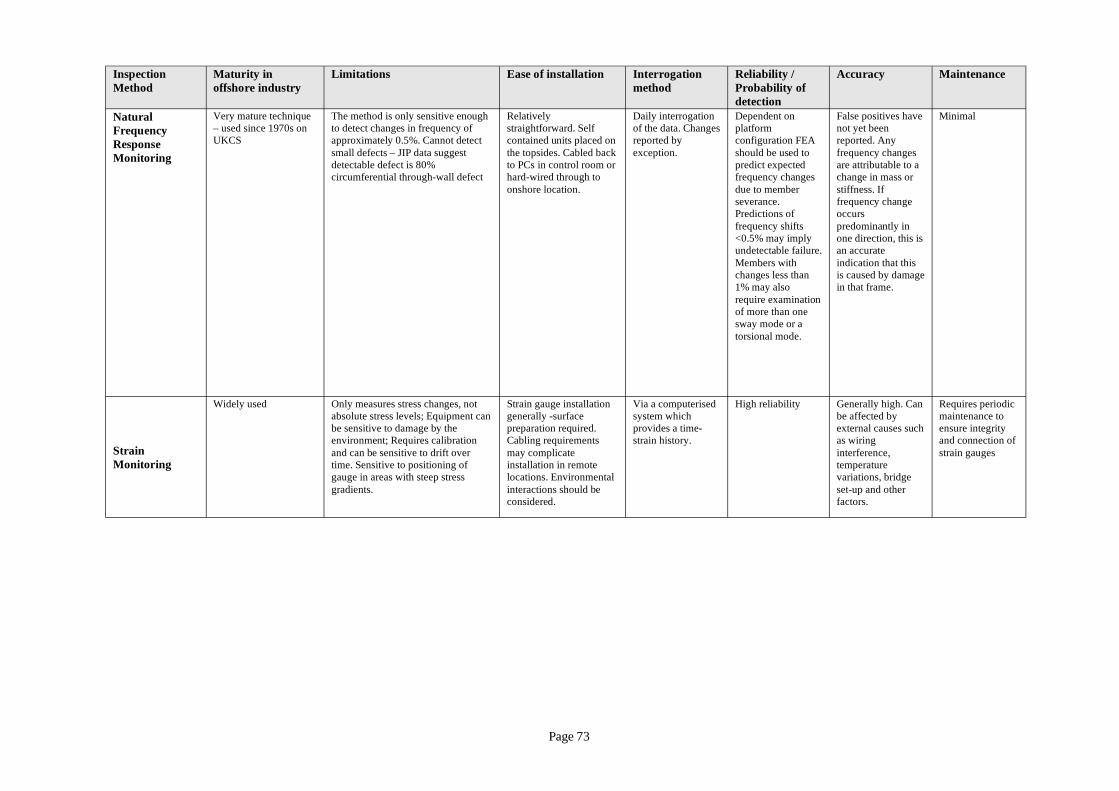
Inspection Maturity in Limitations Ease of installation Interrogation Reliability / Accuracy Maintenance Method offshore industry method Probability of
detection Natural Frequency Response Monitoring
Very mature technique – used since 1970s on UKCS
The method is only sensitive enough to detect changes in frequency of approximately 0.5%. Cannot detect small defects – JIP data suggest detectable defect is 80% circumferential through-wall defect
Relatively straightforward. Self contained units placed on the topsides. Cabled back to PCs in control room or hard-wired through to onshore location.
Daily interrogation of the data. Changes reported by exception.
Dependent on platform configuration FEA should be used to predict expected frequency changes due to member
False positives have not yet been reported. Any frequency changes are attributable to a change in mass or stiffness. If
Minimal
severance. Predictions of
frequency change occurs
frequency shifts <0.5% may imply undetectable failure.
predominantly in one direction, this is an accurate
Members with indication that this changes less than 1% may also require examination of more than one
is caused by damage in that frame.
sway mode or a torsional mode.
Widely used Only measures stress changes, not Strain gauge installation Via a computerised High reliability Generally high. Can Requires periodic absolute stress levels; Equipment can generally -surface system which be affected by maintenance to be sensitive to damage by the preparation required. provides a time- external causes such ensure integrity
Strain Monitoring
environment; Requires calibration and can be sensitive to drift over time. Sensitive to positioning of gauge in areas with steep stress
Cabling requirements may complicate installation in remote locations. Environmental
strain history. as wiring interference, temperature variations, bridge
and connection of strain gauges
gradients. interactions should be set-up and other considered. factors.
Page 73

APPENDIX 3
SIMoNet abstracts
Page 74
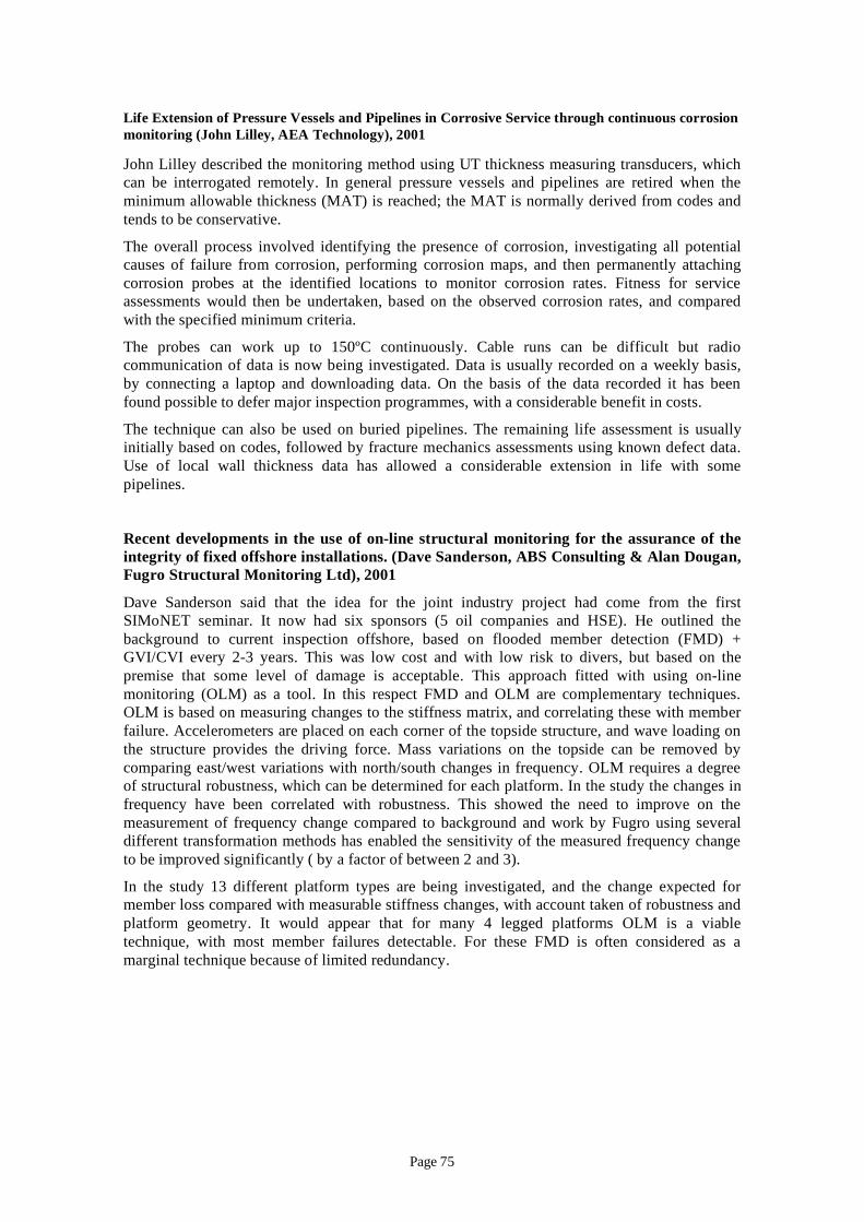
Life Extension of Pressure Vessels and Pipelines in Corrosive Service through continuous corrosion monitoring (John Lilley, AEA Technology), 2001
John Lilley described the monitoring method using UT thickness measuring transducers, which can be interrogated remotely. In general pressure vessels and pipelines are retired when the minimum allowable thickness (MAT) is reached; the MAT is normally derived from codes and tends to be conservative.
The overall process involved identifying the presence of corrosion, investigating all potential causes of failure from corrosion, performing corrosion maps, and then permanently attaching corrosion probes at the identified locations to monitor corrosion rates. Fitness for service assessments would then be undertaken, based on the observed corrosion rates, and compared with the specified minimum criteria.
The probes can work up to 150ºC continuously. Cable runs can be difficult but radio communication of data is now being investigated. Data is usually recorded on a weekly basis, by connecting a laptop and downloading data. On the basis of the data recorded it has been found possible to defer major inspection programmes, with a considerable benefit in costs.
The technique can also be used on buried pipelines. The remaining life assessment is usually initially based on codes, followed by fracture mechanics assessments using known defect data. Use of local wall thickness data has allowed a considerable extension in life with some pipelines.
Recent developments in the use of on-line structural monitoring for the assurance of the integrity of fixed offshore installations. (Dave Sanderson, ABS Consulting & Alan Dougan, Fugro Structural Monitoring Ltd), 2001
Dave Sanderson said that the idea for the joint industry project had come from the first SIMoNET seminar. It now had six sponsors (5 oil companies and HSE). He outlined the background to current inspection offshore, based on flooded member detection (FMD) + GVI/CVI every 2-3 years. This was low cost and with low risk to divers, but based on the premise that some level of damage is acceptable. This approach fitted with using on-line monitoring (OLM) as a tool. In this respect FMD and OLM are complementary techniques. OLM is based on measuring changes to the stiffness matrix, and correlating these with member failure. Accelerometers are placed on each corner of the topside structure, and wave loading on the structure provides the driving force. Mass variations on the topside can be removed by comparing east/west variations with north/south changes in frequency. OLM requires a degree of structural robustness, which can be determined for each platform. In the study the changes in frequency have been correlated with robustness. This showed the need to improve on the measurement of frequency change compared to background and work by Fugro using several different transformation methods has enabled the sensitivity of the measured frequency change to be improved significantly ( by a factor of between 2 and 3).
In the study 13 different platform types are being investigated, and the change expected for member loss compared with measurable stiffness changes, with account taken of robustness and platform geometry. It would appear that for many 4 legged platforms OLM is a viable technique, with most member failures detectable. For these FMD is often considered as a marginal technique because of limited redundancy.
Page 75
Classification Society Perspective on Structural Integrity Monitoring. (David Davenport Jones American Bureau of Shipping), 2001
David Davenport Jones introduced this topic as 'part of the regime that maintains ships' integrity'. It is necessary to understand the strengths and weakness of design using advanced methods, e.g.
– analysis of static and dynamic loads and the resistance to failure modes;
– monitor construction especially critical areas, ie NDT and survey;
– monitor condition and capability of the vessel and the role of coatings;
– link the previous three phases by information management (IT).
He highlighted the necessity for an excess of capability over demand and the fact thatClassification Societies have prescriptive rules to define requirements.
Three main phases were described.
1. Design phase with a safe hull regime to define loads, understand failure modes, set criteria for lifetime safety and, after identification of critical areas for robustness and steel weight distribution, to supply a graphical display of acceptable thickness.
2. Construction phase where the safe hull concept identifies critical areas, requires a monitoring plan from the shipyard and ensures rigorous implementation of this during construction.
3. Operational phase where periodic survey is a guide by analysis of service experience using accumulated information from many sources.
Inherent in this is a need for robustness and here Mr Jones introduced the concept of residual resistance factor and showed how this interacted with OLM and changes in the structural vibrational frequencies. Several frequency transforms were tried and the simple Fourier was found to be most suitable.
A Better Way to Monitor Hull Structures. (John Waite, The Salvage Association), 2001
The Salvage Association ( a trading style of BMT Salvage Ltd) specialises in damage surveillance for insurance purposes. Many excellent slides from a wide variety of sources were a feature of this presentation which included:
– Cracking in the cross bar supports of the StÝreboelt bridge sections;
– The difficulty of photographing grooving in inaccessible places even though it was readily visible to the eye;
– Small cracks in fruit juice containment vessels which, being on a chilled ship were perhaps not so significant and were on a neutral axis so not as subject to bend loads;
– Bow fatigue where a large chunk was missing; the problem being that selective gauging was not at relevant places;
– A centreline girder crack where fracture through the depth of the web and over 70% wastage precluded load bearing;
– Use of ABS, Safenet and Timeline graphic representations were described.
The importance of monitoring coatings in maintaining structural integrity, especially where pitting was a problem. Increasing use of IT was called for to 'put the information where it's needed'. This must include vessel drawings, maintenance modules, current structural condition and most importantly, where the monitors are.
Page 76
2001
The author's conclusion were:
– Whereas classification originally assessed risk, a risk-based approach can now assess and limit it;
– SI monitoring was the sole responsibility of the Classifier and not the owners;
– IT should give everyone the information they need.
FOINAVON Umbilical Monitoring System, SI monitoring -VIV Considerations, (Geoff Lyons, Mechanical Engineering Dept. UCL in collaboration with MIT Norwegian Inst of S&T and BP),
Vortex-induced vibrations (VIV)occur on the Foinavon flexible risers at up to 600m off the Shetlands. The problem was to measure the bending and tensile stress at the vessel in respect of the following topics:
– did the expectations match the realities;
– measurements of responses to mooring/wave/VIV frequencies were expected to be minutes/4-20 secs/ up to 10 Hz;
– measurement of accumulated damage was required;
– by implication one would expect similarities with the risers themselves;
– examine VIV and establish feedback for future design;
– measure asset integrity.
A multi-cored curve sensor was incorporated with the riser which passed through a bend constrictor in the hull bottom. The curvature was sensed throughout the riser and tensions andcurves associated with heave, roll and pitch were determined.
Planar plots were made and the curvature converted to displacements by FE analysis.
VIV measurements were made for varying currents at known depths.
The conclusion was that VIV can be reasonable modelled - both current and vessel motionsreduce VIV. A fibre optic approach was suggested for the future.
Continuous Structural Integrity Monitoring of Offshore Structural Nodes, John O'Brien, Physical Acoustics Ltd, 2002
An overview of Acoustic emission (AE) in providing continuous monitoring of fatigue damage in structural members (e.g. offshore welded nodes) was provided. Types of equipment, software and remote interfaces for accurate monitoring, discrimination of events and swift data processing were presented, based on work at Cardiff University. This is achieved through detecting and locating active emissions and discrimination is feasible to discard emissions due to crack rubbing. A particular application for offshore structures and nodes as an aid to ensuring structural integrity is proving effective enabling a focus on critical areas and nodes. Some trials had been undertaken on a box girder bridge over the M6 motorway and on an offshore floating installation. Cost effective reporting had been achieved via a secure automated web site.
Page 77
2002 Cost Effective Structural Monitoring: an Acoustic Method, Mark Harper, Mecon Ltd,
This presentation outlined the development of a practical use of AE in continuous monitoring of multiply connected structures, such as North Sea offshore installations. It was based on data generated on a plastic wire frame model at a scale of 1:100, simulating a jacket structure by fixing transmitters and receivers to monitor acoustic functions to detect and locate changes in acoustic response. The conclusions were that AE is applicable to such complex structures. This is achieved through a modified time step method to model and characterise transmissions, hence allowing damage location to b ahieved. Locating the transmitters above water line was considered key in obtaining cost effective and realistic data. Further work was planned both using the technique on the existing model and also on a steel structure.
Monitoring with ACFM - Martin Lugg, TSC Ltd, 2002
Martin Lugg outlined how ACFM had originally developed to replace ACPD for underwater crack sizing, and then listed the advantages the technique had for inspection. ACFM is now able to provide many benefits in crack growth monitoring, the main preserve of ACPD. Martin listed the advantages and disadvantages of ACFM and ACPD for monitoring and gave examples of results obtained for both techniques. Finally, two potential future applications for ACFM monitoring were described - monitoring existing cracks underwater during the winter, and remote monitoring of unmanned installations.
Condition Assessment of Ageing Pipelines', Malcolm Wayman , Advanced Engineering Solutions Ltd., 2002
Malcolm outlined the work undertaken by his company, on condition management of ageing pipelines ranging in diameter from 3" to 72". Assessment of the smaller iron pipes involved the checking of critical sections, using external inspection. Samples were often cut out, shot blasted and inspected for defects. Pipeline coatings could be a problem, particularly for the older lines. Corrosion modelling was used to predict life.
For the larger diameter pipelines inspection was for both internal and external corrosion. Stress analysis using FE methods was used to assess critical sections, factors of safety and remaining life. A critical parameter was the remaining wall thickness. The company used a 'bath tub' curve approach, working in the design zone and attempting to predict the end of life section of the curve.
Acoustic emission monitoring of Advanced Composites, Chris Rowland, Pancom, 2003
Chris Rowland described acoustic emission testing and its principles, mainly used for GRP tanks and vessels and more recently CFRP type structures. Examples of testing of aero-engine parts, satellite structures, FI racing cars and hip joints were shown. Glue line unzipping was a recognised problem and examples of this were also shown.. F1 car components were proof tested for each race. The basis of the 'felicity ratio' (FR) was described; results less than unity indicating permanent damage. Sites of failure and damage were shown linked to values of the FR. Difficulties with composite structures using AE were high attenuation, a noisy material and the need for a history to determine levels of significant damage. Overall AE was a proven technique, which was now being transferred to CFRP type structures with some success.
Page 78
SI Monitoring in a Marine Environment, David Sanderson, MMI Engineering
David Saunderson outlined the background to flooded member detection and integrity assessment of jacket type structures using this technique. He then described the development of an on-line device for detection of flooded members, in a project about to start with funding from NESTA, HSE and BP. The device consists of a passive detection unit that is inside tubular members of jackets. When it is activated by becoming wet a signal is emitted which can be detected externally. A preliminary feasibility study has shown that signals can be transmitted acoustically to a receiver. Small scale trails have been undertaken on a model of the Thistle jacket which demonstrated that acoustic transmission was feasible. MMI will be providing the technical guidance with UMIST developing the laboratory model and prototypes. In due course field testing of the device would be undertaken and a suitable site still had to be located. One of the objectives of the programme was to select the optimum modes and frequency for effective transmission through the structure, recognising that losses do occur at nodes. The power requirements also have to be established, together with a suitable power source to provide long term energy. In discussion it was noted that the device is primarily for fitting to new structures, and individual devices would need to be coded in some way so that their position could be identified if a signal was received.
Structural monitoring of wave and tidal energy devices – Prof. J.V.Sharp (Cranfield University) 2003
Prof. Sharp outlined the background to the growth of renewable energy in the UK, with a government target of 10% contribution by 2010. Offshore wind was an area of very fast growth whereas wave and tidal were still at the research and demonstration stage, but would be expected to contribute to the UK supply by 2020. Several wave and tidal devices were now at large or close to full scale and he explained the application of sensing systems in these. These included Limpet (Wavegen) , which is an oscillating water column device, based on Islay, already producing power to the local grid. In this case wave pressure was being measured at the front of the collector and up to 4 bars had been recorded from wave slam. The Pelamis wave energy unit, being developed by Ocean Power Delivery Ltd has been tested at several different scales, and was now being developed at full scale for testing at the Orkney test site, early in 2004. This included extensive structural monitoring, with 16 strain gauges at each joint. Data would also be collected from the mooring system. In future machines a fatigue logging system was planned, based on strain gauges at each joint. Two UK tidal stream devices were currently being tested at close to full scale. These included Stingray (Engineering Business Ltd). This was a hydroplane device, with an advanced control system to optimise the power developed on each stroke. It had been deployed in Yell Sound (Shetlands) in September 2002 and generated power. Further testing was underway in 2003. Sensors were being used to measure loads between the hydroplane and the main arm, as well bending loads in the hydroplane structural tubes.
The second large scale tidal stream device is Seaflow (Marine Current Turbines Ltd) which is a 300kW unit installed in the sea , off Lynmouth, in the summer of 1993. It is an underwater turbine installed on a 2m diameter pile. Strain gauges are located in the pile base, on the rotor blades and accelerometers are positioned at the top of the pile and in a rotor tip blade. Dynamic and static loads are being monitored on the pile. Lift and drag forces are being monitored on the rotor blades, as inputs to the assessment of fatigue and the onset of significant cavitation. Data collection is continuing now the turbine is installed. There are plans to develop a larger 1 MW unit, with two turbines on a single pile. Overall structural monitoring is playing a key part in the development of wave and tidal systems.
Page 79
Structural Instrumentation for the Renewable Energy industry – lessons from offshore oil and gas, A.Dougan, Fugro Structural Monitoring, 2003
Alan Dougan explained how on-line instrumentation had been used to benefit the development of offshore oil and gas structures. Projects such as Shell’s Tern and BP’s Magnus had provided a much better understanding of the loading on these platforms, enabling more efficient designs to be developed for future structures. Monitoring of damage on offshore structures, such as that on the Ninian Southern platform, gave confidence that operations could continue whilst repairs were being planned and undertaken. He also outlined the background to an ongoing research project relevant to wind farms, which was the development of suction piles. These were an alternative to piled foundations, with significant potential costs savings per foundation. . Fugro was one of the companies involved in the project.
He outlined the large planned growth of the offshore wind industry, in similar offshore environments and proposed that on-line monitoring could also be very beneficial in this industry as well and hopefully the developers would take the opportunity at an early stage. Key issues with offshore wind towers are their dynamic response and strength, whilst for piled foundations their stiffness and possible scour were important factors. The addition of simple structural instrumentation to enable their response to be measured would provide confidence and valuable feedback to enable future structures to be optimized, with potential costs savings.
Wave Dragon, Duncan Dunce, Babcocks, 2003
Duncan Dunce explained the background to the wave dragon wave energy device. It is an ‘overtopping’ type unit, fitted with a low head turbine, slack moored, with 2 deflector arms. The device originated in the 1980’s and with funding becoming available in the 1990’2 has been tested at model scale. A large scale prototype has been built in Denmark (57m between the arms) which was launched in March 2003. There are a number of project partners, including Aalborg University and Babcocks. It is being tested at a Danish site, which has less extreme conditions than the unit has been designed for. A second site has also been selected for testing with more demanding environmental conditions. In May 2003 the unit was operating and supplied electricity to the Danish grid for a short time. Improvements have since been made to the device. Monitoring systems have been built into the device, both for condition and structural monitoring. A webcam is also available to monitor performance. For structural monitoring strain gauges and accelerometers are being used; an area of particular interest is the joint between the arm and the main body. Work has already started on a larger scale device, aimed at producing power in the MW range.
Permanent Structural Monitoring using Guided Waves for oil Industry structures, Dr.P.Fromme, Dept. of Mechanical Engineering, UCL, 2003
Technical machinery and systems are subject to varying or cyclic service loads and environmental influences, like adverse weather conditions. Such operation conditions can lead to the development of faults during the lifecycle of the structure, e.g., fatigue cracks and severe corrosion damage in offshore oil platforms and oil storage tanks. This damage can lead to the malfunction and ultimately failure of such structures, endangering lives and the environment.
Fast inspection of large areas of plate-like structures can be achieved employing guided ultrasonic waves. Guided ultrasonic wave testing utilizes a lower frequency region than standard ultrasonic testing (UT), usually in the order of several hundred kHz. The excited wave has a mode shape through the thickness of the structure and can propagate over large distances along the structure. Such measurements have been successfully performed on pipelines, where
Page 80
propagation distances of up to hundreds of meters were realized. This allows the fast and cost-efficient monitoring of difficult-to-access structures from a single sensor location.
For the practical long-term monitoring of structural integrity, a permanently attached guided ultrasonic wave array prototype is being designed and built. The prototype is developed as a remote sensor that runs autonomously, i.e., independent of external energy supply, and transmits data about the condition of the structure wirelessly using a Bluetooth connection. The array consists of a ring of piezoelectric transducer elements for excitation and reception of the guided wave. The properties and coupling of the transducers has been studied and optimized to achieve a sufficient excitation amplitude and good measurement sensitivity. The development of the compact array device for the inspection of large areas with minimum power consumption, necessary for long term operation independent of external power sources, is described. The array operation and data processing schemes are shown and first laboratory measurement results presented.
The sensitivity of the measurement method to typical structural defects is studied experimentally and theoretically. The reflection and mode conversion of the employed guided ultrasonic wave at model defects and structural features is calculated numerically employing a three-dimensional finite element code and verified in laboratory experiments. Corrosion damage often results in large area thickness reduction and is modelled as a circular part-through hole. The scattering and mode conversion of the first antisymmetric Lamb wave mode A0 at such defects is studied. Good agreement with measurement results in the laboratory is found and the sensitivity of the guided wave measurement to such a kind of defect can be predicted.
Monitoring Using the Stress Probe, Nicholas Stone. TSC Inspection Systems, 2004
TSC Inspection Systems has developed the Stress Probe system for measuring stresses in a number of components including threads, welded components and forgings. In order to measure stress in these components the system takes advantage of magnetic property changes in the material, due to the application of mechanical stress. The system can detect the change in magnetic properties, or more specifically permeability, by the use of multiple induced fields and sensor coils encased in a non-contacting probe. The sign of the change in permeability depends on the relative directions of the stress & applied magnetic field, and on whether the stress is tensile or compressive.
Until recently the use of Stress Probe was limited to those applications where the material was of ferromagnetic type and so therefore, obviously, metallic. With new research it has been possible to develop a sensor patch system whereby a suitable material can be inserted into or on the surface of non-metallic structures. This patch can then convey the representative stress from the component to the StressProbe device in the conventional manner. During tests on the new composite riser technology, being developed by a number of oil and gas companies, this new patch sensor system performed exceptionally well. The implications of the success of this approach means that the StressProbe system is no longer limited to ferromagnetic applications and can be employed on a much larger selection of components in service.
Page 81
The story of Buchan Alpha, David Linkens, Atkins, 2005
This talk gave an overview of the Buchan Alpha production platform, and the structural issues which have been dealt with, to enable it to operate successfully and safely for the last 25 years.
Originally constructed as a drilling rig, Drillmaster, it was converted by BP to a production platform from 1978-1981. It is now under the ownership of Talisman Energy. During the conversion work, in 1980, the worst offshore disaster of the decade occurred. The Alexander Kielland, a sister platform, broke up in a storm, and overturned within 30 minutes, with the loss of 123 lives.
An urgent and thorough review was carried out by BP, and independently by Sir High Ford. A number of necessary improvements were made, to ensure structural safety. The floating pentagon design of the 1970's has a lack of redundancy in the tubular bracework which connects the five pontoons. To operate safely it is necessary to apply a stringent ongoing inspection regime, to detect any fatigue cracking well before it becomes critical.
Several photographs of the original construction, and transport of various node sub-assemblies, and assembly afloat at Normandy were shown. The range of inspection approaches which are used to manage the integrity were described, including installation of an acoustic monitoring system in recent years.
In this talk it was shown how vigilance and ongoing attention have enabled a critical structure to operate safely, and to continue to do so.
Ageing Offshore Structures, Dr.John Sharp (Cranfield University) and Dr.Alex Stacey (HSE), 2005
Dr.Sharp said that many offshore structures were now beyond their original design lives and that life extension was now being demonstrated. There were a number of hazards to ageing structures which included fatigue, extreme weather, subsidence and accidental damage. He also showed the ‘bath tub’ curve, with three phases (early life failures, constant failure rate and the wear out phase) and indicated that although an increase in failures would be expected in the wear-out phase due to ageing it was not clear on what timescale this would occur. Life extension was addressed in a number of codes and standards and in particular the draft ISO 19902 standard on fixed steel structures [6] had a new section on assessment of existing structures. Reassessment included condition monitoring, and this was an area where structural monitoring could play a significant part. Structural vibration monitoring and acoustic emission had been sued in the past to monitor defects and there was a new development of fatigue sensors which could be useful in life extension assessment. It was concluded that SI monitoring techniques were improving and new developments in vibration monitoring were indicating significant promise. However it was felt that the offshore industry did not yet fully appreciate the benefits of SI monitoring and that SIMoNET could play an important part in publicising these techniques.
Page 82
Measurement of Marine Fouling, Dr. Martin Lugg, TSC Inspection Systems, 2005
Dr. Lugg explained that TSC Inspection Systems are best known for the ACFM technique for crack detection and sizing. However, the company has also developed a couple of spin-off applications using the same electromagnetic technology. One is the measurement of stress in steel, the other is the measurement of lift-off (the distance between a probe and a metal surface).
ACFM probes are normally designed to minimise the effect of lift-off, but for spin-off applications, probes are instead designed to maximise the effect. This is done by using a field direction perpendicular to the metal surface and using balanced differentially-wound sensor coils.
TSC have produced probes suitable for a variety of applications from pipe ovality measurement, where sub-millimetre accuracy is required up to marine fouling thickness measurement where separation from the metal surface can be up to 300mm.
Marine growth is a problem for offshore structures, especially in warm waters, because of the increased loading on the structure caused by increased drag. Conventional methods of measuring marine growth thickness (encircling tape measure by diver or calipers by ROV) only provide an average thickness. However, marine growth is usually unevenly distributed and local thickness variations influence both the loading and the procedure for removal.
The probe developed by TSC, deployable by diver or ROV, provides spot measurements of marine fouling thickness to an accuracy of about ±10% on any tubular steel member. The system has been used in waters off Australia and Thailand and is expected to be used in similar waters more widely in the future.
Fatigue Damage sensor for welded structures, Peter Tubby, , 2005
Peter Tubby described CrackFirst™ [12] which is a new fatigue damage sensor system specifically designed for welded steel structures. It was developed within a DTI funded collaborative project managed by TWI, involving Caterpillar Peterlee, Micro Circuit Engineering Ltd, Fatigue Monitoring Bureau and UMIST. The CrackFirst™ sensor itself consists of a thin metallic coupon containing a central fatigue crack, which is attached to the structure adjacent to a critical welded joint. Stress cycles in the structure cause extension of the fatigue crack, the magnitude of which is proportional to the cumulative fatigue damage in the target joint. Sensor readings therefore provide an estimate of the rate at which the structure's design life is being consumed, allowing the remaining safe life to be estimated and service inspection intervals to be defined on the basis of usage.
A combination of capacitor discharge welded studs and adhesive bonding is used to attach the sensor to the structure. A tensile pre-stress induced in the coupon during attachment ensures that it responds to both tensile and compressive applied load cycles, in the same way as a welded joint containing tensile residual stress. Sensor electronics with an expected battery life of ten years are used to interrogate the sensor and store results, which can be downloaded to a PC for further analysis. Twelve sequential step changes in the electrical output occur during the life of the sensor.
Fatigue tests on fillet welded plate specimens under constant amplitude loading were conducted to check sensor performance. In all cases the sensors failed before the test joints, the sensor giving a characteristic fatigue endurance similar to the ‘Class F’ design curve in the UK fatigue design rules for welded steel structures. The sensor therefore matches the design fatigue strength of typical fillet welded details such as stiffeners or other welded attachments commonly used in plate structures.
Page 83
Variable amplitude loading measured by Caterpillar on an articulated truck undergoing endurance trials in a quarry was also used in the validation. For the particular sequence investigated, test lives of the welded joints were significantly greater than predicted by Miner’s rule, due to stress cycle interactions resulting in crack growth retardation. A similar effect was observed in the sensors, although in all cases they still failed conservatively, i.e. before the test welds. These results suggest that the CrackFirst™ sensor will provide a more accurate assessment of damage accumulation than conventional methods based on strain cycle counting and Miner’s rule. Further tests under different loading sequences are planned to explore this.
Field trials on earth moving equipment, ships and offshore structures are planned. TWI is in the final stages of development and in bringing the system to market. Companies interested in using the system are invited to contact the author.
Acoustic emission monitoring and its application on structures, Jon Watson, Physical Acoustics, 2005
Jon Watson gave a presentation on the use of Acoustic emission (AE) monitoring on civil and offshore structures. He gave a brief summary on the wide variety of steel structures that Physical Acoustics have worked on which included (amongst other things) steel box girders, welded I beams, orthotropic bridge decks, various bridge bearings and shear studs.
Differences in AE monitoring strategy and use were defined.
Global monitoring – used to identify damage hotspots and also strategically to screen large numbers or large areas of structures for active defects
Semi Global monitoring – used for detailed investigations of structures, commonly those that have already been identified as having potential problems.
Local monitoring – highly accurate active source location used on structural details and areas of concern, commonly applied on welds and bearing.
Tying in with the days earlier presentation by Atkins, Jon summarised Physical Acoustics long term continuous AE monitoring project on the Buchan Alpha platform, shown pictures of the installation and data from the commissioning. The AE system on Buchan Alpha automatically updates a secure website accessible to authorized persons on and offshore with the latest monitoring information. The system has now been running continuously for almost 4 years.
In the final slides of the presentation another example of long term monitoring on Thelwall Viaducts roller bearings was shown. This system monitored the cracking occurring within the rollers and utilised “feature data extraction” which enabled differentiation between noise from bearing movement and that from fracture. Transient signal feature extraction is essential for monitoring on bridge structures and is available on all Physical Acoustics AE systems.
The presentation was concluded with reference to the Highways Agency’s Advice note BA 79 “Management of Substandard Structures” saying that AE monitoring met the requirements for monitoring and that the technical application of AE on civil structures would be specifically covered within an extension to the current Highways Agency Advice Note BA 86/04 on Non Destructive Testing, which is expected to be published in 2006.
Page 84
IRIS-RMS Riser Monitoring System, Donogh Lang, Alan Dougan, MCS/Fugro, 2006
The talk described the IRIS RMS (Riser Monitoring System) which is an advisory system for deepwater drilling risers. It combines measurements of deepwater riser response parameters with a state-of-the-art finite element model to accurately determine the 3D riser response to a wide range of loading scenarios, including transient events, such as vessel drift-off. This is achieved by the incorporation of MCS' industry-leading riser analysis software Flexcom and Freecom in the RMS analysis engine.
A key advantage of the RMS is its ability to improve operational safety. The IRIS RMS achieves this by providing both an accurate record of riser joint usage (including fatigue damage) on a joint-by-joint basis, and a predictive riser response capability. This allows management of the riser components in such a way so as to maximise riser integrity, and has the further advantage of reducing unnecessary drilling down-time.
Page 85
APPENDIX 4
Review of relevant SI Monitoring Techniques in other Industries
Shipping
Structural monitoring in the form of strain monitoring has been applied in the shipping industry for a number of years now. It has been made primarily for monitoring in-service cracks but can be installed before launch. It is often used in regions of structural problem afterwards, to help diagnose and predict future defects, after remedial works. Larger monitoring systems have been used on oil tankers and bulk carriers, but these are not suitable for smaller vessels where space can be at a premium. This has led to the development of smaller systems in recent years. Accurate measurements of both peak and cyclic strains are required for reliable fatigue and ultimate strength predictions.
Aerospace
Comparative Vacuum Monitoring (CVMTM) is a technique that has been developed for use in the aerospace industry. The technique has been independently tested and is being used by several major aerospace manufacturers and military organisations. The system monitors crack initiation and crack growth and works by positioning a sensor directly in an area that is of concern. The sensor is directly in contact with the material and contains many small cavities, some of which are connected to atmospheric pressure and some to a low vacuum source. The sensors are simply adhered to a prepared surface. If a through-wall crack initiates and passes through an atmospheric cavity into a vacuum cavity, fluid begins to flow which is subsequently measured. The monitoring of the measured flow rate serves as the basis for the system.
No electrical hard wiring is required, however if the system is to be monitored from a centralised location, small pneumatic piping is required. The technique is capable of detecting cracks as small as 1mm but this is strongly dependent on the local geometry. Advantages of this system are that it is small, has a high probability of detection and can be installed in places with relatively poor accessibility. The system is also low-maintenance and requires calibration every 12 months. Disadvantages are that the technique does not cover a large area and is only really relevant to locations known to be at a high risk of fatigue cracking. Additionally, the system needs to be managed by a suitably qualified and experienced person.
Process
Acoustic emission is used increasingly commonly during pressure testing of vessels, both static and railroad transportable (there is an ASME code case 1968-1 which permits this formally).
It is used during the pressure test to highlight areas that need closer inspection by NDT, such as MPI or ultrasonic techniques. These techniques complement each other.
Similar AE technology has been deployed by Transneft, Gazprom, Lukoil, SIBUR, Caprolactam and many other process and Oil and Gas companies, often operating in harsh environments.
Page 86
Power Generation
Leak before break is an important integrity argument in safety cases for high pressure steam pipework and vessels. Steam leakage is detected by different means (including moisture detection in the building and acoustic detection).
Marine renewables
Wave and tidal are still at the research and demonstration stage, but would be expected to contribute to the UK supply by 2020. Several wave and tidal devices are now tested at large or close-to-full scale. The application of sensing systems to these tests is described below. The Pelamis wave energy unit, being developed by Ocean Power Delivery Ltd has been tested at several different scales. This included extensive structural monitoring, with 16 strain gauges at each joint. Data would also be collected from the mooring system. In future machines a fatigue logging system is planned based on strain gauges at each joint. Two UK tidal stream devices have been tested at close to full scale. These included Stingray (Engineering Business Ltd). This had been deployed in Yell Sound (Shetlands) in September 2002. Further testing was undertaken in 2003. Sensors were being used to measure loads between the hydroplane and the main arm, as well bending loads in the hydroplane structural tubes.
The second large scale tidal stream device is Seaflow (Marine Current Turbines Ltd) which is a 300kW unit installed in the sea, off Lynmouth, in the summer of 1993. It is an underwater turbine installed on a 2m diameter pile. Strain gauges are located in the pile base and on the rotor blades. Accelerometers are positioned at the top of the pile and in a rotor blade tip. Dynamic and static loads are monitored on the pile. Lift and drag forces are also monitored on the rotor blades, and the result used to assess fatigue and the extent of cavitation. Overall structural monitoring is playing a key part in the development of wave and tidal systems.
SimoNet
SIMoNet (structural integrity monitoring network) is a joint venture between industry and government organisations, managed by University College London to facilitate communication between workers, researchers and all those interested in the field of SI monitoring and Non-destructive Testing. It organises regular and well attended seminars together with an active website (www.simonet.org.uk). Over the course of the programme, a number of presentations specifically relevant to the offshore industry have been given. Abstracts of these are provided in Appendix B.
Page 87

APPENDIX 5
Qualitative Review of Inspection and SI Monitoring Techniques
Page 88
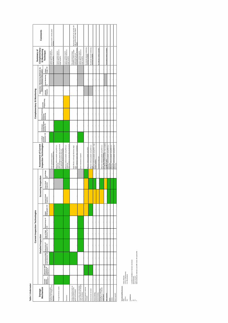
Tabl
e 1
Und
erw
ater
Cur
rent
Insp
ectio
n Te
chno
logi
es
Com
plem
enta
ry S
I Mon
itorin
g Su
mm
ary
of
Dam
age
A
sses
smen
t of C
urre
nt
Insp
ectio
n / M
onito
ring
Met
hods
for
Com
plem
enta
ryD
etai
led
Insp
ectio
n Sc
reen
ing
Insp
ectio
n C
omm
ents
Loca
lised
C
ontin
uous
N
atur
al F
requ
ency
D
etec
ting
Rel
ated
Info
rmat
ion
Mec
hani
sm
Insp
ectio
n Te
chno
logi
es
SI M
onito
ring
Aco
ustic
Fl
oode
d M
embe
r R
espo
nse
Aco
ustic
Fl
oode
d U
ltras
onic
Wal
l Te
chni
que
Emis
sion
s *L
R
Det
ectio
n *R
M
onito
ring
Fing
erpr
intin
gC
onve
ntio
nal N
DE*
* Pu
lse
Echo
UT
Tim
e of
Flig
ht
Phas
ed A
rray
UT
Dig
ital
Gen
eral
Vis
ual
Clo
se V
isua
l Lo
ng R
ange
C
atho
dic
Stra
in M
onito
ring
Fatig
ueM
embe
r Th
ickn
ess
(0
crac
k de
tect
ion
*LD
(an
gled
) *LD
D
iffra
ctio
n *L
D
*LD
R
adio
grap
hy *L
D
Insp
ectio
n In
spec
tion
UT
Prot
ectio
n *L
G
auge
*LR
Det
ectio
n *L
de
gree
s) *L
Sur
face
bre
akin
g cr
acks
C
urre
nt m
etho
d re
quire
s (c
ritic
al to
the
inte
grity
of t
he
Div
er in
volv
emen
t req
uire
d;
subs
ea fi
tting
of s
enso
rs to
C
anno
t scr
een
a w
hole
jack
et
stru
ctur
e)
--
high
-
--
med
ium
-
-lo
w
Loca
l effe
ctiv
e in
spec
tion
only.
hi
gh
--
--
Rel
evan
t R
elev
ant
targ
et lo
catio
ns.
stru
ctur
e
Effe
ctiv
e m
etho
d av
aila
ble
usin
g R
OV
(i.e
. C
urre
nt m
etho
d re
quire
s Th
roug
h-th
ickn
ess
crac
ks
FMD
/CV
I);
Oth
er te
chni
ques
requ
ire d
iver
invo
lvem
ent;
subs
ea fi
tting
of s
enso
rs to
ta
rget
loca
tions
.N
ot a
pplic
able
to b
race
s w
hich
are
hi
gh
-hi
gh
high
hi
gh
high
hi
gh
-lo
w
high
in
tent
iona
lly d
esig
ned
to b
e flo
oded
. hi
gh
high
-
--
Rel
evan
t R
elev
ant
Cur
rent
met
hod
requ
ires
Sev
eran
ce
Effe
ctiv
e m
etho
d av
aila
ble
usin
g R
OV
(i.e
. FM
D/C
VI);
su
bsea
fitti
ng o
f sen
sors
to
targ
et lo
catio
ns.
high
-
high
hi
gh
high
hi
gh
high
m
ediu
m
high
hi
gh
Oth
er te
chni
ques
requ
ire d
iver
invo
lvem
ent.
high
hi
gh
med
ium
m
ediu
m
-R
elev
ant
Rel
evan
t
Sur
face
bre
akin
g cr
acks
at
One
pot
entia
l tec
hniq
ue
mul
tiple
loca
tions
on
the
FMD
effe
ctiv
e at
thro
ugh
thic
knes
s st
age
avai
labl
e to
det
ect m
ultip
le
Mon
itorin
g m
etho
ds d
o no
t hel
p w
ith
jack
et (n
ot lo
calis
ed)
only
; cr
acks
whi
ch a
re n
ot
wid
e sp
read
ear
ly s
tage
fatig
ue
--
high
-
--
med
ium
-
--
Oth
er m
etho
ds re
quire
div
er in
volv
emen
t. -
--
--
--
nece
ssar
ily th
roug
h-th
ickn
ess.
cr
acks
Far-
surfa
ce a
nd e
mbe
dded
C
urre
nt m
etho
d re
quire
s cr
acks
(crit
ical
to th
e in
tegr
ity
Div
er in
volv
emen
t req
uire
d.
subs
ea fi
tting
of s
enso
rs to
of
the
stru
ctur
e)
targ
et lo
catio
ns.
--
-hi
gh
high
hi
gh
med
ium
-
-lo
w
high
-
--
-R
elev
ant
Rel
evan
t
Sev
ere
gene
ral
exte
rnal
co
rros
ion
No
dire
ctly
rele
vant
mon
itorin
g -
high
-
--
-m
ediu
m
med
ium
m
ediu
m
high
E
ffect
ive
met
hod
avai
labl
e us
ing
RO
V.
--
--
Rel
evan
t -
-te
chni
que
avai
labl
e.
Sev
ere
loca
l cor
rosi
on
Effe
ctiv
e m
etho
d av
aila
ble
usin
g R
OV
(i.e
. N
o di
rect
ly re
leva
nt m
onito
ring
-hi
gh
--
--
high
m
ediu
m
high
m
ediu
m
CV
I).
--
--
Rel
evan
t -
-te
chni
que
avai
labl
e.
Sev
ere
dent
ing
Effe
ctiv
e m
etho
d av
aila
ble
usin
g R
OV
- m
ay
--
--
--
-m
ediu
m
high
-
requ
ire c
lean
ing.
-
--
--
--
Sev
ere
bow
ing
--
--
--
-m
ediu
m
--
Cov
ered
by
RO
V G
VI
--
--
--
-N
o ef
fect
ive
met
hod
avai
labl
e.
Dam
age
to s
uppo
rting
st
eelw
ork
e.g.
con
duct
or
Effe
ctiv
e m
etho
d av
aila
ble
usin
g R
OV
(i.e
. gu
ide
fram
e -
--
--
--
med
ium
hi
gh
-C
VI)
- may
requ
ire c
lean
ing.
-
--
--
--
No
effe
ctiv
e m
etho
d av
aila
ble.
Can
re-ti
ghte
n,
Bol
t loo
seni
ng
--
--
--
--
med
ium
-
poss
ibly
by
RO
V.
--
--
-R
elev
ant
-S
peci
alis
ed m
etho
d av
aila
ble.
E
ffect
ive
met
hod
avai
labl
e us
ing
RO
V (i
.e.
Sco
ur
--
--
--
-hi
gh
high
-
GV
I/ C
VI).
-
--
--
--
Deb
ris
Effe
ctiv
e m
etho
d av
aila
ble
usin
g R
OV
(i.e
. -
--
--
--
high
hi
gh
-G
VI/
CV
I).
--
--
--
-E
ffect
ive
met
hod
avai
labl
e us
ing
RO
V (i
.e.
Mar
ine
grow
th
--
--
--
-hi
gh
high
-
GV
I/ C
VI).
-
--
--
--
Sens
itivi
ty/E
ffect
iven
ess
high
hi
ghly
effe
ctiv
e m
ediu
m
med
ium
effe
ctiv
enes
s lo
w
low
effe
ctiv
enes
s
Lim
itatio
ns
*L
Loca
lised
inst
alla
tion
of s
enso
rs n
eces
sary
*R
R
etro
spec
tive
*D
Div
er re
quire
d **
N
DE
tech
niqu
es re
ferr
ed to
are
MP
I, E
CD
, DP
and
AC
FM
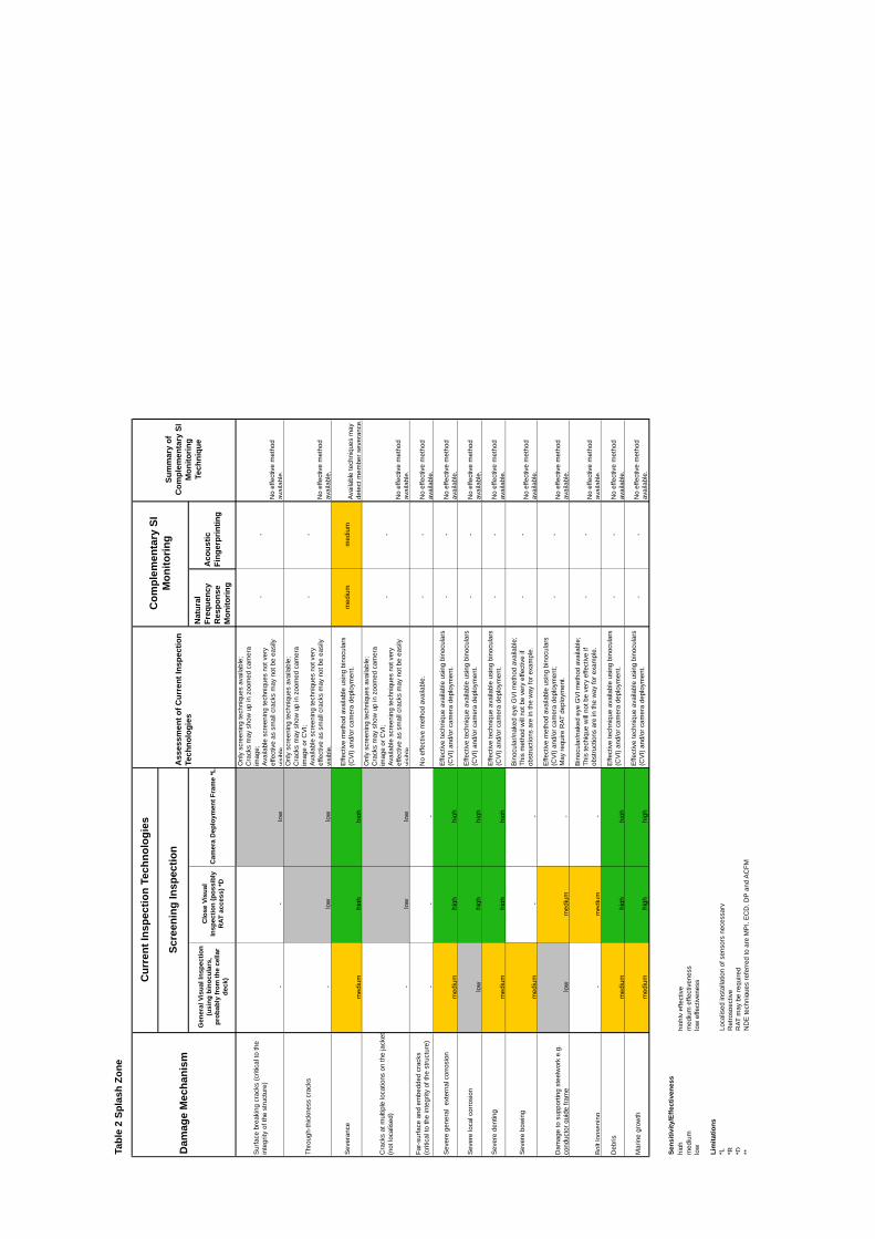
Tabl
e 2
Spla
sh Z
one
Dam
age
Mec
hani
sm
Cur
rent
Insp
ectio
n Te
chno
logi
es
Ass
essm
ent o
f Cur
rent
Insp
ectio
n Te
chno
logi
es
Com
plem
enta
ry S
I M
onito
ring
Sum
mar
y of
C
ompl
emen
tary
SI
Mon
itorin
g Te
chni
que
Scre
enin
g In
spec
tion
Gen
eral
Vis
ual I
nspe
ctio
n (u
sing
bin
ocul
ars,
pr
obab
ly fr
om th
e ce
llar
deck
)
Clo
se V
isua
l In
spec
tion
(pos
sibl
y R
AT a
cces
s) *D
C
amer
a D
eplo
ymen
t Fra
me
*L
Nat
ural
Fr
eque
ncy
Res
pons
e M
onito
ring
Aco
ustic
Fi
nger
prin
ting
Sur
face
bre
akin
g cr
acks
(crit
ical
to th
e in
tegr
ity o
f the
stru
ctur
e)
--
low
Onl
y sc
reen
ing
tech
niqu
es a
vaila
ble;
C
rack
s m
ay s
how
up
in z
oom
ed c
amer
a im
age;
Av
aila
ble
scre
enin
g te
chni
ques
not
ver
y ef
fect
ive
as s
mal
l cra
cks
may
not
be
easi
ly
visi
ble.
--
No
effe
ctiv
e m
etho
d av
aila
ble.
Thro
ugh-
thic
knes
s cr
acks
-lo
w
low
Onl
y sc
reen
ing
tech
niqu
es a
vaila
ble;
C
rack
s m
ay s
how
up
in z
oom
ed c
amer
a im
age
or C
VI;
Avai
labl
e sc
reen
ing
tech
niqu
es n
ot v
ery
effe
ctiv
e as
sm
all c
rack
s m
ay n
ot b
e ea
sily
vi
sibl
e.
--
No
effe
ctiv
e m
etho
d av
aila
ble.
Sev
eran
ce
med
ium
hi
gh
high
Effe
ctiv
e m
etho
d av
aila
ble
usin
g bi
nocu
lars
(C
VI)
and/
or c
amer
a de
ploy
men
t. m
ediu
m
med
ium
Av
aila
ble
tech
niqu
es m
ay
dete
ct m
embe
r sev
eran
ce.
Cra
cks
at m
ultip
le lo
catio
ns o
n th
e ja
cket
(n
ot lo
calis
ed)
-lo
w
low
Onl
y sc
reen
ing
tech
niqu
es a
vaila
ble;
C
rack
s m
ay s
how
up
in z
oom
ed c
amer
a im
age
or C
VI;
Avai
labl
e sc
reen
ing
tech
niqu
es n
ot v
ery
effe
ctiv
e as
sm
all c
rack
s m
ay n
ot b
e ea
sily
vi
sibl
e.
--
No
effe
ctiv
e m
etho
d av
aila
ble.
Far-
surfa
ce a
nd e
mbe
dded
cra
cks
(crit
ical
to th
e in
tegr
ity o
f the
stru
ctur
e)
--
-N
o ef
fect
ive
met
hod
avai
labl
e.
--
No
effe
ctiv
e m
etho
d av
aila
ble.
Sev
ere
gene
ral
exte
rnal
cor
rosi
on
med
ium
hi
gh
high
Effe
ctiv
e te
chni
que
avai
labl
e us
ing
bino
cula
rs
(CV
I) an
d/or
cam
era
depl
oym
ent.
--
No
effe
ctiv
e m
etho
d av
aila
ble.
Sev
ere
loca
l cor
rosi
on
low
hi
gh
high
Effe
ctiv
e te
chni
que
avai
labl
e us
ing
bino
cula
rs
(CV
I) an
d/or
cam
era
depl
oym
ent.
--
No
effe
ctiv
e m
etho
d av
aila
ble.
Sev
ere
dent
ing
med
ium
hi
gh
high
Effe
ctiv
e te
chni
que
avai
labl
e us
ing
bino
cula
rs
(CV
I) an
d/or
cam
era
depl
oym
ent.
--
No
effe
ctiv
e m
etho
d av
aila
ble.
Sev
ere
bow
ing
med
ium
-
-
Bin
ocul
ar/n
aked
eye
GV
I met
hod
avai
labl
e;
This
met
hod
will
not
be
very
effe
ctiv
e if
obst
ruct
ions
are
in th
e w
ay fo
r exa
mpl
e.
--
No
effe
ctiv
e m
etho
d av
aila
ble.
Dam
age
to s
uppo
rting
ste
elw
ork
e.g.
co
nduc
tor g
uide
fram
e lo
w
med
ium
-
Effe
ctiv
e m
etho
d av
aila
ble
usin
g bi
nocu
lars
(C
VI)
and/
or c
amer
a de
ploy
men
t; M
ay re
quire
RAT
dep
loym
ent.
--
No
effe
ctiv
e m
etho
d av
aila
ble.
Bol
t loo
seni
ng
-m
ediu
m
-
Bin
ocul
ar/n
aked
eye
GV
I met
hod
avai
labl
e;
This
tech
ique
will
not
be
very
effe
ctiv
e if
obst
ruct
ions
are
in th
e w
ay fo
r exa
mpl
e.
--
No
effe
ctiv
e m
etho
d av
aila
ble.
Deb
ris
med
ium
hi
gh
high
Effe
ctiv
e te
chni
que
avai
labl
e us
ing
bino
cula
rs
(CV
I) an
d/or
cam
era
depl
oym
ent.
--
No
effe
ctiv
e m
etho
d av
aila
ble.
Mar
ine
grow
th
med
ium
hi
gh
high
E
ffect
ive
tech
niqu
e av
aila
ble
usin
g bi
nocu
lars
(C
VI)
and/
or c
amer
a de
ploy
men
t. -
-N
o ef
fect
ive
met
hod
avai
labl
e.
Sens
itivi
ty/E
ffect
iven
ess
high
hi
ghly
effe
ctiv
e m
ediu
m
med
ium
effe
ctiv
enes
s lo
w
low
effe
ctiv
enes
s
Lim
itatio
ns
*L
Loca
lised
inst
alla
tion
of s
enso
rs n
eces
sary
*R
R
etro
spec
tive
*D
RAT
may
be
requ
ired
**
ND
E te
chni
ques
refe
rred
to a
re M
PI,
EC
D, D
P an
d A
CFM
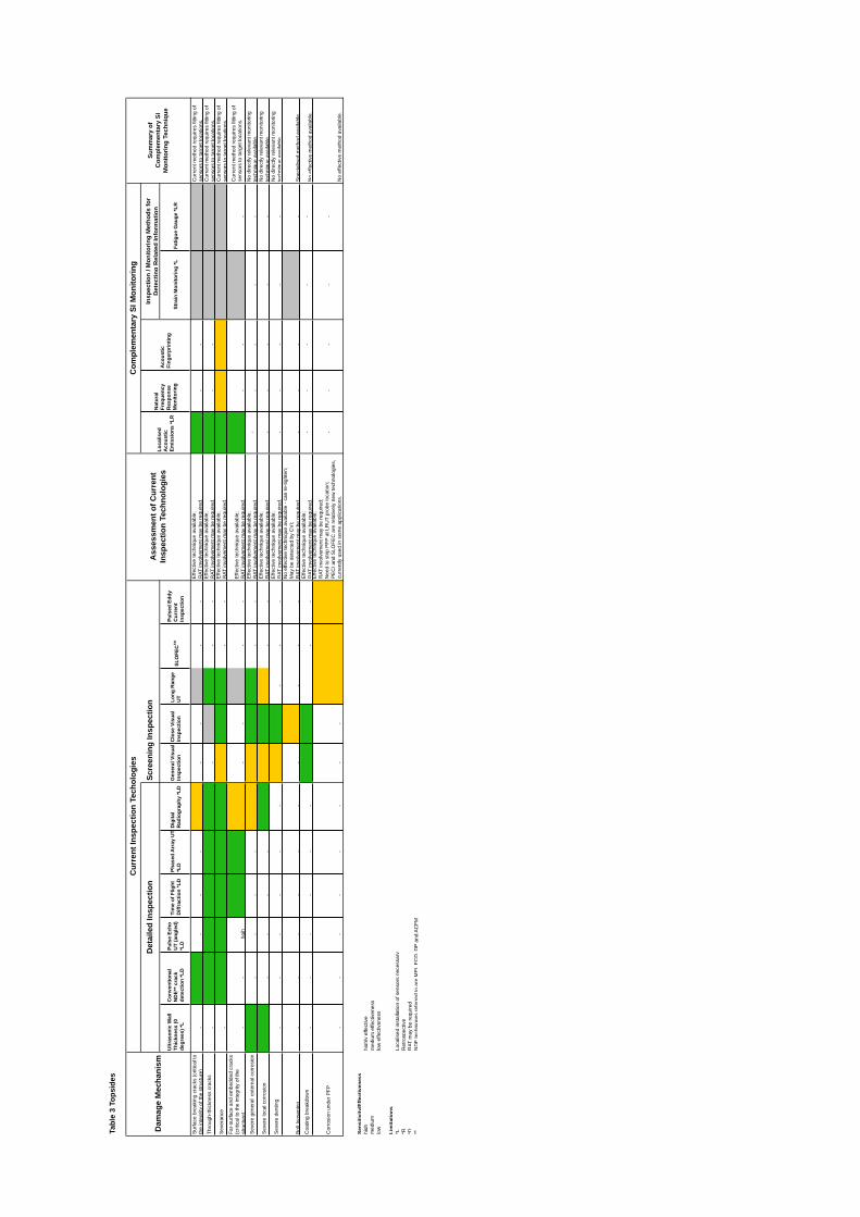
--
--
Tabl
e 3
Tops
ides
Cur
rent
Insp
ectio
n Te
chol
ogie
s C
ompl
emen
tary
SI M
onito
ring
Insp
ectio
n / M
onito
ring
Met
hods
for
Det
aile
d In
spec
tion
Scre
enin
g In
spec
tion
Sum
mar
y of
Ass
essm
ent o
f Cur
rent
N
atur
al
Det
ectin
g R
elat
ed In
form
atio
n C
ompl
emen
tary
SI
Dam
age
Mec
hani
sm
Loca
lised
A
cous
tic
Freq
uenc
y A
cous
ticIn
spec
tion
Tech
nolo
gies
M
onito
ring
Tech
niqu
e Fi
nger
prin
ting
Ultr
ason
ic W
all
Con
vent
iona
l Pu
lse
Echo
Pu
lsed
Edd
y Em
issi
ons
*LR
R
espo
nse
Thic
knes
s (0
N
DE*
* cra
ck
UT
(ang
led)
Ti
me
of F
light
Ph
ased
Arr
ay U
T D
igita
l G
ener
al V
isua
l C
lose
Vis
ual
Long
Ran
ge
Mon
itorin
g St
rain
Mon
itorin
g *L
Fa
tigue
Gau
ge *L
R
degr
ees)
*L
dete
ctio
n *L
D
*LD
D
iffra
ctio
n *L
D
*LD
R
adio
grap
hy *L
D
Insp
ectio
n In
spec
tion
UT
SLO
FEC
TM
Cur
rent
In
spec
tion
Effe
ctiv
e te
chni
que
avai
labl
e;
Sur
face
bre
akin
g cr
acks
(crit
ical
to
Cur
rent
met
hod
requ
ires
fittin
g of
th
e in
tegr
ity o
f the
stru
ctur
e)
-hi
gh
--
-m
ediu
m
--
low
-
-R
AT in
volv
emen
t may
be
requ
ired.
hi
gh
--
Rel
evan
t R
elev
ant
sens
ors
to ta
rget
loca
tions
.
Thro
ugh-
thic
knes
s cr
acks
E
ffect
ive
tech
niqu
e av
aila
ble;
C
urre
nt m
etho
d re
quire
s fit
ting
of
-hi
gh
high
hi
gh
high
hi
gh
-lo
w
high
-
-R
AT in
volv
emen
t may
be
requ
ired.
hi
gh
--
Rel
evan
t R
elev
ant
sens
ors
to ta
rget
loca
tions
.
Sev
eran
ce
Effe
ctiv
e te
chni
que
avai
labl
e;
Cur
rent
met
hod
requ
ires
fittin
g of
-
high
hi
gh
high
hi
gh
high
m
ediu
m
high
hi
gh
--
RAT
invo
lvem
ent m
ay b
e re
quire
d.
high
m
ediu
m
med
ium
R
elev
ant
Rel
evan
t se
nsor
s to
targ
et lo
catio
ns.
Far-
surfa
ce a
nd e
mbe
dded
cra
cks
Cur
rent
met
hod
requ
ires
fittin
g of
Effe
ctiv
e te
chni
que
avai
labl
e;
(crit
ical
to th
e in
tegr
ity o
f the
se
nsor
s to
targ
et lo
catio
ns.
--
hgih
hi
gh
high
m
ediu
m
--
low
-
-R
AT in
volv
emen
t may
be
requ
ired.
hi
gh
--
Rel
evan
t -
Sev
ere
gene
ral
exte
rnal
cor
rosi
on
stru
ctur
e)
Effe
ctiv
e te
chni
que
avai
labl
e;
No
dire
ctly
rele
vant
mon
itorin
g hi
gh
--
--
-m
ediu
m
med
ium
hi
gh
high
-
-R
AT in
volv
emen
t may
be
requ
ired.
-
--
-te
chni
que
avai
labl
e.
Sev
ere
loca
l cor
rosi
on
Effe
ctiv
e te
chni
que
avai
labl
e;
No
dire
ctly
rele
vant
mon
itorin
g hi
gh
--
--
high
m
ediu
m
high
m
ediu
m
--
RAT
invo
lvem
ent m
ay b
e re
quire
d.
--
--
-te
chni
que
avai
labl
e.
Sev
ere
dent
ing
Effe
ctiv
e te
chni
que
avai
labl
e;
No
dire
ctly
rele
vant
mon
itorin
g -
--
--
-m
ediu
m
high
-
RAT
invo
lvem
ent m
ay b
e re
quire
d.
--
--
-te
chni
que
avai
labl
e.
No
effe
ctiv
e te
chni
que
avai
labl
e - c
an re
-tigh
ten;
M
ay b
e de
tect
ed b
y C
VI;
Bol
t loo
seni
ng
--
--
--
-m
ediu
m
-R
AT in
volv
emen
t may
be
requ
ired.
-
--
Rel
evan
t -
Spe
cial
ised
met
hod
avai
labl
e.
Coa
ting
brea
kdow
n E
ffect
ive
tech
niqu
e av
aila
ble;
-
--
--
--
--
--
high
hi
gh
--
RAT
invo
lvem
ent m
ay b
e re
quire
d.
No
effe
ctiv
e m
etho
d av
aila
ble.
E
ffect
ive
tech
niqu
e av
aila
ble;
R
AT in
volv
emen
t may
be
requ
ired;
C
orro
sion
und
er P
FP
Nee
d to
stri
p P
FP a
t LR
UT
prob
e lo
catio
n;
--
--
-P
EC
I and
SLO
FEC
are
rela
tivel
y ne
w te
chno
logi
es,
--
--
--
--
med
ium
m
ediu
m
med
ium
cu
rren
tly u
sed
in s
ome
appl
icat
ions
. N
o ef
fect
ive
met
hod
avai
labl
e.
Sens
itivi
ty/E
ffect
iven
ess
high
hi
ghly
effe
ctiv
e m
ediu
m
med
ium
effe
ctiv
enes
s lo
w
low
effe
ctiv
enes
s
Lim
itatio
ns
*L
Loca
lised
inst
alla
tion
of s
enso
rs n
eces
sary
*R
R
etro
spec
tive
*D
RAT
may
be
requ
ired
**
ND
E te
chni
ques
refe
rred
to a
re M
PI,
EC
D, D
P an
d A
CFM
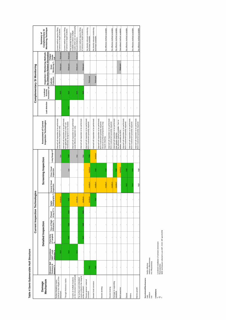
Tabl
e 4
Sem
i-Sub
mer
sibl
e H
ull S
truc
ture
Dam
age
Mec
hani
sm
Cur
rent
Insp
ectio
n Te
chno
logi
es
Ass
essm
ent o
f Cur
rent
In
spec
tion
Tech
nolo
gies
Com
plem
enta
ry S
I Mon
itorin
g
Sum
mar
y of
C
ompl
emen
tary
SI
Mon
itorin
g Te
chni
que
Det
aile
d In
spec
tion
Scre
enin
g In
spec
tion
Leak
det
ectio
n Lo
calis
ed
Aco
ustic
Em
issi
ons
*LR
Insp
ectio
n / M
onito
ring
Met
hods
fo
r Det
ectin
g R
elat
ed In
form
atio
n U
ltras
onic
Wal
l Th
ickn
ess
(0
degr
ees)
*L
Con
vent
iona
l N
DE*
* cra
ck
dete
ctio
n *L
Puls
e Ec
ho
UT
(ang
led)
*L
Tim
e of
Flig
ht
Diff
ract
ion
*L
Phas
ed
Arr
ay U
T *L
D
igita
l R
adio
grap
hy *L
Gen
eral
Vis
ual
Insp
ectio
n C
lose
Vis
ual
Insp
ectio
n Lo
ng R
ange
UT
Cat
hodi
c Pr
otec
tion
Stra
in
Mon
itorin
g *L
Fatig
ue
Gau
ge
*LR
S
urfa
ce b
reak
ing
crac
ks
(crit
ical
to th
e in
tegr
ity o
f the
st
ruct
ure)
-
high
-
--
med
ium
-
-lo
w
Inte
rnal
hul
l ins
pect
ion
to b
e pe
rform
ed;
Loca
l effe
ctiv
e in
spec
tion
only.
-
high
-
Rel
evan
t R
elev
ant
Cur
rent
met
hod
requ
ires
fittin
g of
sen
sors
to ta
rget
loca
tions
.
Thro
ugh-
thic
knes
s cr
acks
-hi
gh
high
hi
gh
high
hi
gh
-lo
w
high
Inte
rnal
hul
l ins
pect
ion
to b
e pe
rform
ed;
Not
app
licab
le to
bra
ces
whi
ch a
re
inte
ntio
nally
des
igne
d to
be
flood
ed.
high
hi
gh
-R
elev
ant
Rel
evan
t
Cur
rent
met
hod
requ
ires
fittin
g of
sen
sors
to ta
rget
loca
tions
.
Cra
cks
at m
ultip
le lo
catio
ns
on th
e st
ruct
ure
(not
loca
lised
) -
high
-
--
med
ium
-
-lo
w
Inte
rnal
hul
l ins
pect
ion
to b
e pe
rform
ed;
Loca
l effe
ctiv
e in
spec
tion
only.
-
high
-
Rel
evan
t R
elev
ant
One
pot
entia
l tec
hniq
ue
avai
labl
e to
det
ect m
ultip
le
crac
ks w
hich
are
not
nec
essa
rily
thro
ugh-
thic
knes
s.
Far-
surfa
ce a
nd e
mbe
dded
cr
acks
(crit
ical
to th
e in
tegr
ity
of th
e st
ruct
ure)
-
-hi
gh
high
hi
gh
med
ium
-
-lo
w
Inte
rnal
hul
l ins
pect
ion
to b
e pe
rform
ed.
-hi
gh
-R
elev
ant
-
Cur
rent
met
hod
requ
ires
fittin
g of
sen
sors
to ta
rget
loca
tions
.
Sev
ere
gene
ral
exte
rnal
co
rros
ion
high
-
--
-m
ediu
m
med
ium
m
ediu
m
high
Inte
rnal
hul
l ins
pect
ion
to b
e pe
rform
ed;
RO
V in
volv
emen
t pos
sibl
y re
quire
d.
--
Rel
evan
t -
-N
o di
rect
ly re
leva
nt m
onito
ring
tech
niqu
e av
aila
ble.
Sev
ere
loca
l cor
rosi
on
high
-
--
-hi
gh
med
ium
hi
gh
med
ium
In
tern
al h
ull i
nspe
ctio
n to
be
perfo
rmed
. -
-R
elev
ant
--
No
dire
ctly
rele
vant
mon
itorin
g te
chni
que
avai
labl
e.
Sev
ere
dent
ing
--
--
--
med
ium
hi
gh
-
Inte
rnal
hul
l ins
pect
ion
to b
e pe
rform
ed;
RO
V in
volv
emen
t pos
sibl
y re
quire
d;
Stru
ctur
al s
urfa
ce/c
ompo
nent
s m
ay
requ
ire c
lean
ing.
-
--
--
No
effe
ctiv
e m
etho
d av
aila
ble.
Sev
ere
bow
ing
--
--
--
med
ium
-
-
Inte
rnal
hul
l ins
pect
ion
to b
e pe
rform
ed;
RO
V in
volv
emen
t pos
sibl
y re
quire
d.
--
--
-N
o ef
fect
ive
met
hod
avai
labl
e.
Dam
age
to s
uppo
rting
st
eelw
ork
--
--
--
med
ium
hi
gh
-In
tern
al h
ull i
nspe
ctio
n to
be
perfo
rmed
-m
ay re
quire
cle
anin
g.
--
--
-N
o ef
fect
ive
met
hod
avai
labl
e.
Bol
t loo
seni
ng
--
--
--
-m
ediu
m
-N
o ef
fect
ive
met
hod
avai
labl
e. C
an re
-tig
hten
, pos
sibl
y by
RO
V.
--
-R
elev
ant
-S
peci
alis
ed m
etho
d av
aila
ble.
Ssc
our
--
--
--
high
hi
gh
-
Inte
rnal
hul
l ins
pect
ion
to b
e pe
rform
ed;
RO
V in
volv
emen
t pos
sibl
y re
quire
d.
--
--
-N
o ef
fect
ive
met
hod
avai
labl
e.
Deb
ris
--
--
--
high
hi
gh
-
Inte
rnal
hul
l ins
pect
ion
to b
e pe
rform
ed;
RO
V in
volv
emen
t pos
sibl
y re
quire
d.
--
--
-N
o ef
fect
ive
met
hod
avai
labl
e.
Mar
ine
grow
th
--
--
--
high
hi
gh
-In
tern
al h
ull i
nspe
ctio
n to
be
perfo
rmed
; R
OV
invo
lvem
ent p
ossi
bly
requ
ired.
-
--
--
No
effe
ctiv
e m
etho
d av
aila
ble.
Sens
itivi
ty/E
ffect
iven
ess
high
hi
ghly
effe
ctiv
e m
ediu
m
med
ium
effe
ctiv
enes
s lo
w
low
effe
ctiv
enes
s
Lim
itatio
ns
*L
Loca
lised
inst
alla
tion
of s
enso
rs n
eces
sary
*R
R
etro
spec
tive
**
ND
E te
chni
ques
refe
rred
to a
re M
PI,
EC
D, D
P an
d A
CFM
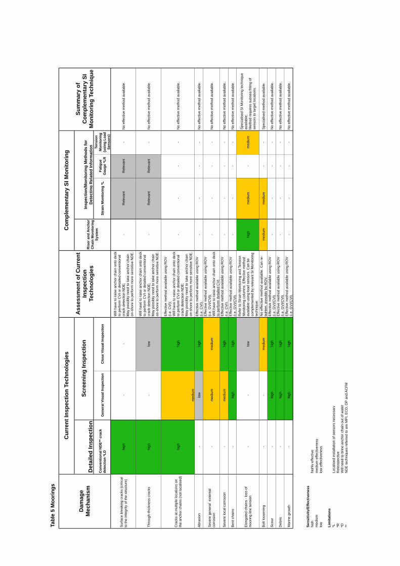
Tabl
e 5
Moo
rings
Dam
age
Mec
hani
sm
Cur
rent
Insp
ectio
n Te
chno
logi
es
Ass
essm
ent o
f Cur
rent
In
spec
tion
Tech
nolo
gies
Com
plem
enta
ry S
I Mon
itorin
g
Sum
mar
y of
C
ompl
emen
tary
SI
Mon
itorin
g Te
chni
que
Det
aile
d In
spec
tion
Scre
enin
g In
spec
tion
Ris
er a
nd A
ncho
r C
hain
Mon
itorin
g Sy
stem
Insp
ectio
n/M
onito
ring
Met
hods
for
Det
ectin
g R
elat
ed In
form
atio
n
Con
vent
iona
l ND
E** c
rack
de
tect
ion
*LD
G
ener
al V
isua
l Ins
pect
ion
Clo
se V
isua
l Ins
pect
ion
Stra
in M
onito
ring
*L
Fatig
ue
Gau
ge *L
R
Tens
ion
Mon
itorin
g (u
sing
Loa
d Se
nsor
s)
Sur
face
bre
akin
g cr
acks
(crit
ical
to
the
inte
grity
of t
he s
truct
ure)
hi
gh
--
Will
hav
e to
rais
e an
chor
cha
in o
nto
deck
to
per
form
CV
I or d
etai
led
conv
entio
nal
crac
k de
tect
ion
ND
E;
May
pos
sibl
y ne
ed to
take
anc
hor c
hain
on
-sho
re to
per
form
mor
e se
nsiti
ve N
DE
.
-R
elev
ant
Rel
evan
t -
No
effe
ctiv
e m
etho
d av
aila
ble.
Thro
ugh-
thic
knes
s cr
acks
hi
gh
-lo
w
Will
hav
e to
rais
e an
chor
cha
in o
nto
deck
to
per
form
CV
I or d
etai
led
conv
entio
nal
crac
k de
tect
ion
ND
E;
May
pos
sibl
y ne
ed to
take
anc
hor c
hain
on
-sho
re to
per
form
mor
e se
nsiti
ve N
DE
.
-R
elev
ant
Rel
evan
t -
No
effe
ctiv
e m
etho
d av
aila
ble.
Cra
cks
at m
ultip
le lo
catio
ns o
n th
e an
chor
cha
ins
(not
loca
lised
) hi
gh
med
ium
high
Effe
ctiv
e m
etho
d av
aila
ble
usin
g R
OV
(i.
e. C
VI);
W
ill h
ave
to ra
ise
anch
or c
hain
ont
o de
ck
to p
erfo
rm C
VI o
r det
aile
d co
nven
tiona
l cr
ack
dete
ctio
n N
DE
; M
ay p
ossi
bly
need
to ta
ke a
ncho
r cha
in
on-s
hore
to p
erfo
rm m
ore
sens
itive
ND
E.
--
--
No
effe
ctiv
e m
etho
d av
aila
ble.
Abr
asio
n -
low
hi
gh
Effe
ctiv
e m
etho
d av
aila
ble
usin
g R
OV
(i.
e. C
VI).
-
--
-N
o ef
fect
ive
met
hod
avai
labl
e.
Sev
ere
gene
ral
exte
rnal
co
rros
ion
-m
ediu
m
med
ium
Effe
ctiv
e m
etho
d av
aila
ble
usin
g R
OV
(i.
e. G
VI/C
VI);
W
ill h
ave
to ra
ise
anch
or c
hain
ont
o de
ck
to p
erfo
rm d
etai
led
CV
I.
--
--
No
effe
ctiv
e m
etho
d av
aila
ble.
Sev
ere
loca
l cor
rosi
on
-m
ediu
m
high
E
ffect
ive
met
hod
avai
labl
e us
ing
RO
V
(i.e.
CV
I).
--
--
No
effe
ctiv
e m
etho
d av
aila
ble.
Ben
t cha
ins
-hi
gh
high
E
ffect
ive
met
hod
avai
labl
e us
ing
RO
V
(i.e.
GV
I/CV
I).
--
--
No
effe
ctiv
e m
etho
d av
aila
ble.
Elo
ngat
ed c
hain
s - l
oss
of
moo
ring
line
tens
ion
--
low
Ref
er to
Stra
in M
onito
ring
and
Tens
ion
Mon
itorin
g co
lum
ns. E
ffect
ive
met
hod
avai
labl
e us
ing
load
sen
sors
. Can
be
com
plem
ente
d by
rele
vant
SI M
onito
ring
tech
niqu
e.
high
m
ediu
m
-m
ediu
m
Spe
cial
ised
SI M
onito
ring
tech
niqu
e av
aila
ble;
M
etho
d re
quire
s su
bsea
fitti
ng o
f se
nsor
s to
targ
et lo
catio
ns.
Bol
t loo
seni
ng
--
med
ium
N
o ef
fect
ive
met
hod
avai
labl
e. C
an re
-tig
hten
, pos
sibl
y by
RO
V.
med
ium
m
ediu
m
--
Spe
cial
ised
met
hod
avai
labl
e.
Sco
ur
-hi
gh
high
E
ffect
ive
met
hod
avai
labl
e us
ing
RO
V
(i.e.
GV
I/CV
I).
--
--
No
effe
ctiv
e m
etho
d av
aila
ble.
Deb
ris
-hi
gh
high
E
ffect
ive
met
hod
avai
labl
e us
ing
RO
V
(i.e.
GV
I/CV
I).
--
--
No
effe
ctiv
e m
etho
d av
aila
ble.
Mar
ine
grow
th
-hi
gh
high
E
ffect
ive
met
hod
avai
labl
e us
ing
RO
V
(i.e.
GV
I/CV
I).
--
--
No
effe
ctiv
e m
etho
d av
aila
ble.
Sens
itivi
ty/E
ffect
iven
ess
high
hi
ghly
effe
ctiv
e m
ediu
m
med
ium
effe
ctiv
enes
s lo
w
low
effe
ctiv
enes
s
Lim
itatio
ns
*L
Loca
lised
inst
alla
tion
of s
enso
rs n
eces
sary
*R
R
etro
spec
tive
*D
Will
nee
d to
brin
g an
chor
cha
in o
ut o
f wat
er
**
ND
E te
chni
ques
refe
rred
to a
re M
PI,
EC
D, D
P an
d A
CFM
Appendix 6 Structural Integrity Monitoring of Moorings
Mooring Inspections
Inspection of wire ropes and anchor chains is a specialised area and it is not intended to cover all aspects of mooring inspection and monitoring here. Typically, for in-service monitoring, load sensors are used as tension monitoring systems on risers and anchor chains. Anchor chains may be brought out of the water for visual inspections. For more detailed investigation, i.e. NDE, the anchor chain may need to be taken on-shore. ROV inspections can also be carried out on the anchor chains in-situ. This is inherently error-prone and unreliable particularly if long lengths of anchor chain are to be inspected.
In order to improve quality of in-situ mooring chain inspection, TWI are currently developing and testing an automated vehicle which will be able to detect fatigue cracks, corrosion, bent chains and abrasion. Reference [14] indicates that the vehicle will have an onboard cleaning kit which would be able to clear away marine growth and corrosion scale, to allow NDT to be carried out. This technology is still in the development and testing phase.
SI Monitoring of Moorings
The Riser and Anchor Chain Monitoring System has been developed to provide continuous monitoring of the presence, position and tension of moorings in-situ. Refer to Section 4.10 for overview of technique.
The table below is a summary of SI monitoring techniques which can potentially complement current mooring chain inspections for selected damage mechanisms. Information is taken from Table 5 in Appendix 4.
Complementary SI Monitoring Techniques – Moorings
Damage Mechanism
Assessment of Current Inspection Technologies
Complementary SI Monitoring Technique(s)
Breakage Effective method available using ROV (i.e. GVI/CVI).
May need to raise anchor chain onto deck to perform CVI or detailed conventional crack detection NDE.
RACM
Loss of mooring line tension
Effective method available using load sensors. Can be complemented by relevant SI monitoring technique.
RACM
Bolt loosening No effective method available. Can re-tighten, possibly by ROV.
RACM
Page 94
Mooring Line Breakage
ROV inspections for a mooring line breakage would be to locate the breakage point. Inspections may not identify a severed line if the ROV is not targeted at the right place. This method can therefore be unreliable. Additional costs and health and safety risks will have to be considered when bringing the anchor chain onto deck for more detailed CVI.
SI monitoring methods such as RACM may be used to continuously monitor the global position and tension of anchor chains/mooring lines so that severance can be detected as soon as it occurs without the need to raise the anchor chain onto the deck for every scheduled inspection.
Loss of Mooring Line Tension
Strain monitoring and load sensors may be used to provide relevant information on the tension of the mooring lines, and can be useful tools for the inspection of mooring lines.
In addition, SI monitoring techniques such as RACM may be used to continuously monitor mooring line tension. Sensors attached to the mooring lines feed-back positional and tensile loading information.
Page 95

Published by the Health and Safety Executive 01/09
Executive Health and Safety
Structural integrity monitoringReview and appraisal of current technologies for offshore applications
With the ageing of the North Sea fleet of platforms and semi-submersibles, the importance of maintaining structural integrity offshore is increasingly recognised and structural inspection plays a significant role in demonstrating ongoing integrity and the potential for life extension. Structural integrity (SI) monitoring can complement existing inspection techniques to provide greater confidence in structural integrity or to reduce inspection cost. It has been found that offshore experience of SI monitoring is limited to date and that current systems are for bespoke applications. This report focuses on fixed steel structures, topsides and semi-submersible hulls.
This report and the work it describes were funded by the Health and Safety Executive (HSE). Its contents, including any opinions and/or conclusions expressed, are those of the authors alone and do not necessarily reflect HSE policy.
RR685
www.hse.gov.uk