STRUCTURAL DESIGN REVIEW OF LONG, · PDF fileSTRUCTURAL DESIGN REVIEW OF LONG, CYLINDRICAL,...
114
SSC-205 STRUCTURAL DESIGN REVIEW OF LONG, CYLINDRICAL, LIQUID-FILLED INDEPENDENT CARGO TANK BARGES This document has been approved for public releaseand sale;its distributionisunlimited. SHIPSTRUCTURECOMMITTEE I 970
-
Upload
duongtuyen -
Category
Documents
-
view
223 -
download
4
Transcript of STRUCTURAL DESIGN REVIEW OF LONG, · PDF fileSTRUCTURAL DESIGN REVIEW OF LONG, CYLINDRICAL,...

SSC-205
STRUCTURAL DESIGN REVIEW OF LONG,CYLINDRICAL, LIQUID-FILLED INDEPENDENT
CARGO TANK BARGES
This document has been approvedfor public releaseand sale;its
distributionis unlimited.
SHIPSTRUCTURECOMMITTEE
I970

MEMBER AGENcIES,
UNITED 5TAT. S COAST GUARD
NAVAL 5$+1, SYSTEMS COMMAND
MILITARY ,..4 TRANSPORTATION SERVICEM& R,,, ME ADM, t4,ST RAT10N
AMERICAN BUREAU 0, SHIPPING
ADDRESS CORRESPONDENCE To:
S. CR ETA-,
5.4P 37 RUCTUF?E COMMITTEE
“.s. COAST G“Ae D HEADQUARTERS
WAS. H4NGTON, D.C. 2059t
1970
Dear Sir:
The possibility of transporting liquid chemical cargoes inlarge tank barges on the open sea has necessitated an assessment ofthe state of the art in barge-tank design, to determine what furthertheoretical and experimental development is required.
Herewith is a final project report containing the reviewand recommendations of the study.
Sincerely,
m~~udActing Chairman, Ship StructureCommittee

SSC-205
FinalReport
on
ProjectSR-184,“ChemicalTank-BargeDesign”
tothe
ShipStructureCommittee
STRUCTURALDESIGNREVIEWOFLONG,CYLINDRICAL,LIQUID-FILLEDINDEPENDENTCARGOTANK-BARGES
by
C.W.BascomGeneralDynamicsGroton,Connecticut
under
DepartmentoftheNavyNAVSECContractNOO024-68-C-5419
This documenthasbeenapprovedfor public release andsale; its distribution is unlimited.
U.S.CoastGuardHeadquartersWashington,D.C.
1970
“.., —

ABSTRACT
Thisreportdescribesa programofanalyticalresearchtodeterminetheavailabilityofreliablemethodsfor thedesignoflong,largediameter,cylindricaltanksandtheirsupportsfortransportationofliquidsandlow-pressureliquifiedgasesinbargesforserviceonriversoratsea. Loadingconditions,ex-istingdesign/analysismethods,materialconsiderations,andacomputermethodforpredictingstressesarepresented.
Themajorconclusionoftheworkperformedisthatdesiqnproceduresfor riverbargetanksupto20feetindiameterarewellestablishedandthatno failuresdueto inadequatedesignpracticehavebeenreportedsincerefrigeratedtankswentintoserviceabouttenyearsago. Thepresentmethodfordesigningriverbargetanksisa logicalstartingpointfordeterminingthestructuralconfigurationoflargetanksforoceanicservice,butmoredetailedanalysisofloadsandresultingstressesshouldbeperformedforthisapplication.
Severalareasinwhichtheoreticalorexperimentaleffortisneededareidentified:(1)investigationoftank-saddle-bainteraction,(2)investigationoffatiguecriteriafor cyclicloading,(3)investigationof bucklingcriteria,(4)analyticaandexperimentalinvestigationofslamming,and(5)experimentaverificationofstressesinafull-scaletank.
ii

CONTENTS
INTRODUCTION.. . . . . . .. . . . . . . . . . . . . .. . . + .
APPROACH. . .
CONCLUSIONSAND
TANKBARGELOAD:
. . . . . . . . . . . . . . . . . . . . . . . . .
RECOMMENDATIONS.. . . . . . .. . . . . . . .. .
NGS.. . . . . . .. . . . . . . . . . . . . .. .
STRUCTURALDESIGN/ANALYSISOFTANKBARGES.. . . . . . . . . . . .
EVALUATIONOFSTRESSESINEXISTINGANDPROJECTEDDESIGNS. .. . .
DISCUSSIONOFMATERIALSANDCONSTRUCTIONOFPRESSUREVESSELSFORBULKTRANSPORTOFLIQUIDCARGOESONBARGES.. . . . . . .. .
ACKNOWLEDGEMENTS.. . . .. . . . . . . . . .. . . . .. . .. .
REFERENCES. . . . .. . . . . . .. . .. . . . . . . ...”” ””
APPENDIXA - INVESTIGATIONOFTHEENVIRONMENTOFLARGEOCEAN-GOINGBARGES.. .. . . . . . . . . . . . . . . . . . . . .
APPENDIXB -ANALYSISOFRINGSTIFFENERS. . . . . . . . . .. . .
APPENDIXC -OUTLINEFORSTRAINGAGEINSTRUMENTATIONOFATANKBARGE.. . . . . . .. . . .. . . . . . . . . . . . ● ● ● “
APPENDIXD - DISCUSSIONOFAPPROACHFORTANK/BARGESLAMMINGTESTS.. . . .. . . . . . . . . . .. . . .. . . . . . . . . .
iii
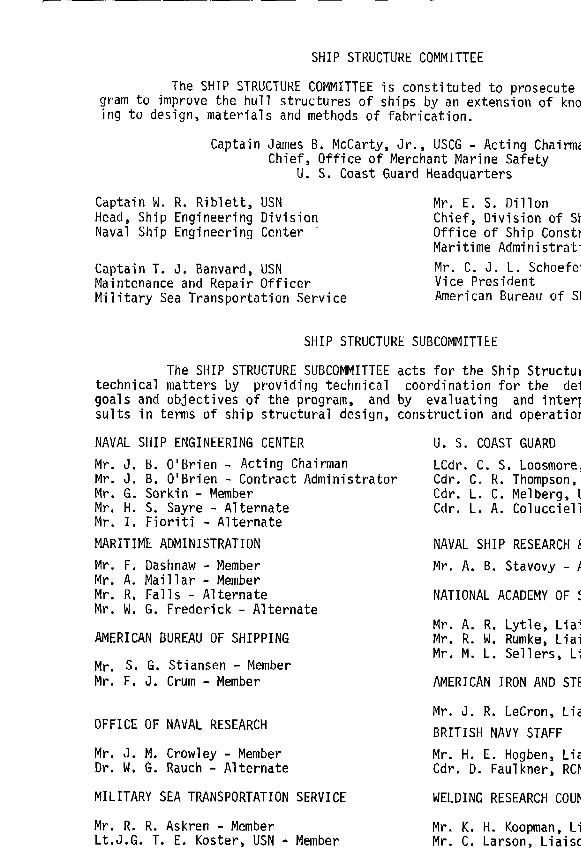
SHIPSTRUCTURECOMMITTEETheSHIPSTRUCTURECOMMITTEEisconstitutedtoprosecu
gramto improvethehullstructuresofshipsbyanextensionofkningtodesign,materialsandmethodsoffabrication.
CaptainJamesB,McCarty,Jr.,USCG- ActingChairChief,OfficeofMerchantMarineSafety
U.S.CoastGuardHeadquarters
CaptainW,R.Riblett,USN Mr.E.S.DillonHead,ShipEngineeringDivision Chief,DivisionofSNavalShipEngineeringCenter OfficeofShipCons
MaritimeAdministCaptainT.J.Banvard,USN Mr,C.J.L.SchoeMaintenanceandRepairOfficer VicePresidentMilitarySeaTransportationService AmericanBureauofS
SHIPSTRUCTURESUBCOMMITTEETheSHIPSTRUCTURESUBCOMMITTEEactsfortheShipStruc
technicalmattersby providingtechnicalcoordinationforthe degoalsandobjectivesoftheprogram,andby evaluatingandintesultsintenmsofshipstructuraldesign,constructionandoperat
NAVALSHIPENGINEERINGCENTERMr.J.B.O’Brien- ActingChairmanMr.J.B.O’Brien- ContractAdministratorMr.G.Sorkin- MemberMr.H.S.Sayre- AlternateMr.1,Fioriti-AlternateMARITIMEADMINISTRATIONMr.F.Dashnaw- MemberMr.A.Maillar- MemberMr.R,Falls- AlternateMr.W.G.Frederick- Alternate
AMERICANBUREAUOFSHIPPING
Mr.S. G,Mr.F.J.
OFFICEOF
Mr.J.M.Dr.W.G.
Stiansen- MemberCrum- Member
NAVALRESEARCH
Crowley- MemberRauch- Alternate
MILITARYSEATRANSPORTATION
Mr.R.R.Askren- MemberLt.J.G.T.E.Koster,USN-
SERVICE
Member
U.S.COASTGUARDLCdr.C.S.LoosmoCdr.C.R.ThompsoCdr.L.C.MelbergUCdr.L.A.Colucci
NAVALSHIPRESEARCMr.A.B.Stavovy-
NATIONALACADEMYOF
&A
S
Mr.A.R.Lytle,LiaMr.R.W.Rumk8,LiaMr.M.L.SellersL
AMERICANIRONANDST
Mr.J.R.LeCron,LiBRITISHNAVYSTAFFMr.H.E.Hogben,LiCdr.D.Faulkner,RC
WELDINGRESEARCHCOU
Mr.K.H.KoopmanLMr.C.Larson,Liai

LISTOFILLUSTRATIONS
Qk3!z94-14-2
4-34-+,
5-15-25-35-45-5
5-65-75-85-95-1o5-11
5-12
5-13
6-16-26-36-46-56-66-76-86-9
A-1A-2A-3A-4A-5A-6A-7A-8A-9
TrendinFundamentalFrequenciesvs. BargelengthBargeVelocityandDistancevs. TimeforConsbntDecelerationof1.5g
AcousticPressurevs. SpeedforVariousBargesAverage1/1OHighestSlammingPeakPressureBendingStressvs. ThicknessforVarious200-FootTanksBendingStressvs. ThicknessforVarious300-FootTanksBendingStressvs. ThicknessforVarious400-FootTanksThreeRepresentativeTankDesignsNondimemionalBucklingCurveforCircularTubesinCompression
Configurationofa TypicalRiverBargeConfigurationofaTypicalOcean-GoingTankBargeTypicalRiverBarge~ctionalViewTypicalOcean-GoingTankBargeSectionalViewTypicalTankCharacteristicsandSaddleSupportsTypicalloading,Shear,andMomentDiagramsfora
GroundedRiverBargeTypicalImading,Shear,andMomentDiagramsforanOcean-GoingTankBarge(SaggingCondition)
TypicalLoading,Shear,andMomentDiagramsforanOcean-GoingTankBarge(HoggingCondition)
TypicalStructuralModelforComputerAnalysisTypicalTankReinforcementAdapWbletoFabrication
E%E
1417191926272829
323434353536
37
39404344
200-FootTank– NormalOperation—ImgitudinalStress(o= O)47200-FootTank- NormalOperation—HoopStress(d=O) 47200-FootTank—Grounding- LongitudinalStress(@=O) 48200-FootTank- Grounding- HoopStress(6=O) 48400-FootTank– NormalOperation—longitudinalStress(0=O)52400-FootTank– NormalOpe=tion- HoopStress(o=o) 52InvestigationofCycliclaadingforFatigueAnalysisof400-FootTank 56
Pitchvs. Speed(NeumannSea) 77BOW Accelerationvs. Speed(NeumannSea) 77RollinRandomBeamSeas(MostProbableRollAngle) 77RollinRandomBeamSeas(Average1/1OHighestAngle) 78WaveLengthsAlongU.S.Coasts 82WaveHeightsAlongU.S.Coasts 82WavePeriodsAlongU.S.Coasts 83FrequencyofEncounterat10Knots 83ComparisonofNaturalPeriods 85
v
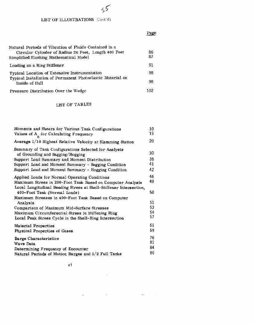
LJ-’LISTOFILLUSTRATIONS,~:o:lt“(i)
NaturalPeriodsofVibrationofFluidsContainedinaCircularCylinderofRadius20Feet,Length400Feet
SimplifiedSloshingMathematicalModelLoadingonaRingStiffenerTypicalLocationofExtensiveInstrumentationTypicalInstallationofPermanentPhotoelasticMaterialon
InsideofHullPressureDistributionOvertheWedge
LISTOFTABLES
MomentsandShearsforVariousTankConfigurationsValuesofAnforCalculatingFrequencyAverage1/1OHighestRelativeVelocityatSlammingStation
8687
9198
98
102
SummaryofTankConfigurationsSelectedforAnalysisof GroundingandSagging/Hogging
SupportIaadSummaryandMomentDistributionSupportImadandMomentSummary- SaggingConditionSupportbad andMomentSummary- HoggingConditionAppliedIaadsforNormalOperatingConditionsMaximumStressin200-FootTankBasedonComputerAnalysisIacalLongitudinalBendingStressatShell-StiffenerIntersection,400-FootTank(Normalhads)
MaximumStressesin400-FootTankBasedonComputerAnalysis
ComparisonofMaximumMid-SurfaceStressesMaximumCircumferentialStressinStiffeningRingImcalPeakStressCycleintheShell-RingIntersectionMaterialPropertiesPhysicalPropertiesofGasesBargeCharacteristicsWaveDataDeterminingFrequencyof EncounterNaturalPeriodsofMotionBargesand1/2FullTanks
101520
303841424649
50
51535457616976818486
vi

Section1 ~b
INTRODUCTION
Thetrendinthedistributionoflargevolumesofindustrialgaseshasbeentowardtherefrigeratedmodeoftransportandstorage.Independenttankbarges‘haveproventobebothpracticalandeconomicalandthismodeoftransportisbeingconsideredforcoastalandoceanicservice.
Dimensionsofriverbargesarelimitedtoapproximately10feetindraft,53feetinwidth,and300feetinlength;thedraftdimensionis controlledbyriverdepth,andlengthandbeambyriverlocksize. Thesedimensionslimitthemaximumcapacityofthebargetoapproximately3,000tons. Thisinturnlimitsthediameterofthecargotankstoapproximately20feetandthelengthtoabout250feet. Twotanksareusuallymountedsidebysideonthebarge,andsupportedonfrom7to13saddles.Stiffenersareinstalledatthesaddlestoaccommodatethehighreactionloadsatthesepoints.Typicaltanksarefabricatedof1/2-inchcarbonmanganesesteel. IXMignpressuresareaslowas4to10psianddesigntemperaturesareapproximately-30°F.Thetanksarecoveredwithapproximatelythreeinchesofinsulation.Redundantrefrigerationplantsandsafetyvalvesareprovidedtoensureagainstoverpressurizingthetanksduetovaporizationofthefluid.
Fromthestructuralpointofview,theselargeriverbargetankshaverelativelysmallthickness-to~iameterratios,i.e., theyarequitethinwalled.Theyoperateessentiallyatatmosphericpressures,andreactionforcesratherthanpressurestressesgovernthedesign.Theempiricalprocedurefordesigningthesetanksforreactionforcesisbasedonexperimentalworkwithstationarytankshavingjusttwosupportsandrelativelyheavierwallsthantoday’slargeriverbargetanks.
Independenttankbargesareenvisionedinthenearfutureforcoastalandtransoceanicservice.Verylargebargesinthe20,000-tonrangeareeconomicallyattractive.Sinceoceanorcoastalbargeswillnotbesubjectedtothedimensionallimitationsofriverbarges,tanksaslargeas40feetwideand400feetlongareenvisioned.
Twomajorquestionsariseconcerningthedesignoflargeoceanservicetankbarges.1. Whatloadingconditionsareapplicabletothedesignoflargecylindrical
tanksforoceanservice?2. Istheempiricalproceduredevelopedforsmaller,heavierwalled
stationarytanksapplicabletothelargersizes? Ifnot,whatis themostreliableprocedure,orwhatfurtherworkisneededtoderiveanadequateprocedure?
Interpretiveanswerstothesequestionshavebeentheprimeobjectiveofthisthree-monthstudy.Thisobjectiveis statedmorefullyinthescheduleofthecontractasfollows:“Analyticalresearchshallbeundertakentodetermineavailabilityofreliablemethods
-

-2-
forthedesignoflong,cylindricaltanks,andtheirsupports,forthetransportationofliquidsandlow-pressureliquifiedgases.inbargesonriversoratsea. Theworkshallinvolve:
1.
2.
3.
4.
Descriptionoftheloadsandloadingconditionswhich-mustbeconsideredintankdesign,forsizesupto40feetindiameterand400feetinlength.Determinationoftheanalyticmethodspresentlyavailableforuseinthedesignoftanksandtheirsupports,wheninstalledinbarges.IJ%erminationofthemostreliablemethodorcombinationofmethodspresentlyavailabletoextendsuchdesign,fromthestandpointofsafety,economy,andefficientdesign,tothelargertanks.Determinationofthoseareasinwhichtheoreticalorexperimentalworkisneeded.‘‘

-Li-
Section2
APPROACH
SixbasictaskswereperformedinordertoaccomplishthefourobjectivesstatedintheIntroduction.
TASKA-TASKB-TASKC-TASKD-TASKE-
TASKF-
InvestigationofChemicalTank/BargeOperatingConditions.InvestigationofTank/BargeLoadings.InvestigationofTank/BargeDesign”Characteristics.EvaluationofStressesinExistingandProjectedDesigns.EngineeringInvestigationofMaterialsProblemsAssociatedwithIargeTanks.PreparationofanInterpretiveReportIncludingRecommendationsforResearchinMajorProblemAreas.
Backgrounddatafortheabovetaskswasobtainedbyreviewingtheliteratureandbycontactingpersonnelinthebargeindustry.Theliteraturereviewisreflectedinthelistofreferences.Muchhelpfulbackgroundmaterialwasobtainedbycontactingregulatingbodies,surveyors,designers,buildersandoperatorsoftankbarges.(SomeofthemanyhelpfulcontactsmadeinthecourseofthestudyarelistedintheAcknowledgements.)
InordertoperformTasksCandD, itwasexpedienttoworkwithspecifictarddbargeconfigurations.Sinceexistingdesignsareofaproprietarynature,twohypotheticaldesigns- onerivertypeandoneoffshoretype- wereselectedforexamination.Thefollowingprocedurewasusedtodeterminetankand’bargecharacteristics.
Configurations,i.e., wallthicknessesandnumberandspacingofstiffeners,weredeterminedforvarioustanklengthsanddiameters.Thesewereaccomplishedbydeterminingreactionsduetotankdeadweightfromelementarystructuraltheory.Dynamicforcesduetopitch,roll,andheavewereaccountedforbyapplyingadynamicloadfactortothestaticforces. Densityofthefluidinthetankswasas-sumedtobe42poundspercubicfoot,whichisrepresentativeofseveralliquifiedgasesnowbeingtransported.Tankshavingfrom2to11saddleswereconsidered.Threefamiliesoftankswereinvestigated:20-footdiametertanks,200feetlong;3O-footdiametertanks,300feetlong;and40-footdiametertanks,400feetlong.Thewallthicknessforeachdiameter,lengthandsupport(numbe~ofsaddles)con-figurationwasdeterminedbyassumingthatthelgoverningcriterionwasthebucklingofshortcylindricalcolumnsasdefinedbyZick. Forselectedlengthsanddiameters,curvesofcriticalstressvs. thicknesswereplottedforconfigurationshavingfrom2to11’supports.Fromthecurves,representativetankwallthicknesseswereselectedforariverbargeandanoffshorebarge,basedonlowerlimitsoftankwallthicknessconsideredpracticalforfabrication.
Rough,structuraldesignswerealsopreparedofariverbargeandanoffshorebargewhichwouldaccommodatethepreviouslyselectedtanks.Thepurposeofthiseffort

-4-wastoobtaintheweight,stiffnessandbuoyancycharacteristicsofthebargeforuseinevaluatingbarge/tankinteractionduetowaveactioninthecaseofanocean-goingtankbargeandgroundinginthecaseofarivertankbarge.
Thetwotank/bargeconfigurationswerethenanalyzedfortheloadingconditionsestablishedinTaskB. Oftheseloadingconditions,themostsevereisgroundingforariverbargeandsagging/hoggingforanoffshorebarge.Reactionforcesweredeterminedfo thesesevereconditionsusingtheiterativeprocedureoutlinedbytheCoastGuard.1.Thmmethodisbasedontheassumptionsthatreactionforcesareprimarilydependentonbendingstiffnessandtheeffectsofshearstiffnessarenegligible.
Stressesintheareaofthesaddleswerethenevaluatedbytwomethod%themethodofZicklwhichisnowcommondesignpracticeandthemethodofKalnins, amoresophisticatedcomputerapproach.Thecalculatedstressesineachcasewerecomparedwithallowablestress. Thisanalysisdemonstratedproceduresofthetwomethodsandcomparedresults,ratherthanevaluatedthehypotheticaldesigns.

-5-
Section3
CONCLUSIONSANDRECOMMENDATIONS
Thissectionsummarizesthemostsignificantconclusionsoftheinvestigationandgivesrecommendationsforfurthertheoreticalandexperimentalwork.Conclusionsre-gardingspecificloadsanddesign/analysisproceduresarecontainedinsections4through7.
Design/analysisproceduresforlow-pressure,refrigeratedtanksforserviceonriversarewellestablished.Asurveyofdesigners,regulatorybodies,builders,surveyors,andoperators“indicatesthatnomajorfailuresduetodesigninadequacyhaveeverbeenreportedsincethistypeofbargecameintoserviceabout10yearsago. Inviewoftheexcellentoperatinghistoryandrecordofrivertankbarges,thedesignproceduresforriverbargetanksofupto20feetindiameterforriverbargeapplicationareconsideredadequate.Inmanycasesoperatorsspecifystructuralstrengthinexcessofregulatorybodyrequirements,
Designproceduresforriverbargesaregenerallyapplicablefordeterminingthebasicconfiguration%oflargertankscontemplatedforoceanservice.Thisconclusionisbasedonthegoodagreementbetweenmidsurfacestressescalculatedbytheestablishedempiricalprocedureandamoresophisticatedcomputeranalysis.How-ever,theempiricalproceduredoesnotgivestressesatenoughpointstofullysatisfyinputsforanalysisofcyclicloadsontanksforoceanserviceandamoredetailedstressanalysiswillberequiredforthiscase. Furthermore,theoreticalpredictionsofstressinlarge,thin-walledmultisupportedtanksshouldbeverifiedexperimentally.Theoreticalpredictionshavebeenverifiedonlyonsmaller,heavy-walledtaokssup-portedonjusttwosaddles.
Iangtanksforoceanservicewillbesubjectedtocyclicloadsandrelativelylargedeflectionsasthebargesagsandhogsduetooceanwaveforces. Cyclicloadsarenotassignificantinriverbargesandtherefore,criteriaforevaluationoftheseloadshavenotbeenestablished.Criteriaforcyclic-loadingandfatigueevaluationincludingfactorsforeffectsofsurfaceimperfectionsshouldbeestablishedforoceantankbarges.Thebargetank/deflectionswillcauseinteractionbetweenthebargestruc-ture,thetankstructure,thesaddlestructure,andthesaddleinsulation.Thespringconstantofthesaddleinsulationmaterialisnonlinearwhichgreatlycomplicatesexactpredictionoftheinteraction.
Duringtheinitialthreemonthswork,severalspecificproblemareasneedingfurtheranalyticalandexperimentalresearchwereidentified.Theseproblemsaregenerallynotapplicabletorivertankbargesnowinservice,butapplytothelargeroceanbargesenvisionedforthefuture.
3.1 EXPERIMENTALANDANALYTICALANALYSESOFANAS-BUILTTANKTheforemostproblemconfrontingthedesigneristhequestionofadequacyofdesign/analysistechniquesavailabletohim. Ourinvestigationtodatehasshowngoodagreementbetweenthesimplifiedapproachnowusedforriverbargesanda moresophisticatednumericalanalysisprocedureofpointsonthetankwherethesimpli-
— — -.

-6-
fiedmethodapplies.Neithermethod,however,hasexperimentaldatatoverifyresultsinthelargersizesenvisionedforoceanbarges.
Atankbargeinthebuildingstageshouldbeinstrumentedwithstraingagesforthepurposeofcheckinganalyticalresults.Thegagescouldremainonthetankafteritisputintoserviceforaspecifiedtimeandrecordingsmadeofstressesundervariousloadingconditions.Furtherdiscussionofanexperimentalprogramiscon-tainedinAppendixC.
3.2 FATIGUEANALYSISInthecourseofthestudy,itbecameevidentthatspecificexperienceindesigninglargethin-walledtankssubjecttocyclicloadsencounteredinoceanserviceisverylimited.Itwasalsoevidentthatthesimplifiedstressanalysisproceduresapproxi-matemembraneormid-fibrestressatselectedpointsonly.Amorecornprehensiveexaminationofstresses,bothinsideandoutsidethetankwall,isnecessaryforafatigue.analysis.Also,allowablestresslimitsforfatigueanalysisoftankmaterialshavenotbeendetermined.Datamayexist,and,if so, itmustbecollectedandrelatedtothetank/bargeapplication.Ifdatadoesnotexist,thenexperimentalworkwillbenecessary.
3.3 BUCKLINGANALYSISThereiswidedivergenceinthecriticalcompressivebucklingstressesdeterminedfrommethodscontainedintheliterature.Forexample,thecriticalbucklingstressasdeterminedbythemethodofTimoshinkoisgreaterbyafactorof2thanthevaluedeterminedbythemethodofZick. Thisareacertainlyneedsfurtherinvestigation.Amoreextensivereviewoftheliteratureandaninvestigationofbucklingcriteriadevelopedforotherapplicationsareproposed.Amodeltestprogrammaybenecessaryifnoapplicabledataisavailable.
3.4 SLAMMINGINVESTIGATIONSlammingisamajorareaofconcerninthedesignofallhullsforoceanservice.Oceantankbargesarenoexceptionwhereslammingloadsappeartoaffectthetankaswellasthebargehullitself. IntheareaoftheforwardrakebuIkhead,slammingmaycauselargedeformationofthehullwhichistransmittedupintotheforwardtanksaddle.Thetanksaddleisseparatedfromthehullbyalayerof insulationwhichmaycushionslammingloads,buttowhatextentthisoccurshasnotbeendetermined.Experimentalworkwithspecificmodelbargehullsshouldbeunder-takentodeterminepressuredistributions.
Thenextstepwouldbetoapplythesepressurestothehulltankstructurewithproperboundaryconditionstodeterminethehull/lankinteraction.Theproblemappearstobequitecomplexbutnotimpossibletosolveutilizingtoday’scomputertechnology.AfurtherdiscussionofamodeltestprogramforinvestigatingtankbargeslammingiscontainedinAppendixD.
3.5 TANK/BARGEANDSADDLEINTEWCTION
.
Theeffectofsaddleflexibilityonsagging/hogginganddynamicloadsshouldbedetermined.Thisproblemcouldbeapproachedbyutilizingamatrixstructuralanalysisprocedure.Thetankandbargewouldeachberepresentedby(n+1)
— -. — —
-7-
stiffnessmatrices,wherenisthenumberofsaddles.Eachsaddlewouldconsistoftwostiffnessmatrices:onefortheinsulationmaterialandoneforthesaddlestruc-ture.Stiffnessoftheinsulationmaterialwouldbedeterminedfromthemanufacturers’dataorfromtesting.Severalanalyseswouldbeperformedtoevaluatetheeffectofhardandsoftsaddles.Uniformload~duetoweightandvariablebuoyancyloadswouldberepresentedbyatleastthreeconcentratedloadsbetweeneachsupport.
.
-8-
Section4
TANKBARGELOADINGS
Refrigeratedcargobargesareoperatedatatmosphericpressure,withthedominantloadbeingcausedbyreactionsatthesupportsduutocargoweightratherthanbypressure.Furthermore,theverylargetanksenvisionedforocean-goingbargeswillbesubjectedtodynamicforces,inadditiontotheweightofthecargo,asthebargepitches,rolls,andheavesinaseaway,andtosaggingandhoggingforcesasthebargehulldeflectswhilewavespassunderit. Saggingandhoggingarecyclicloadsthatcausethefati~uestrengthofthetanktobeanimportantconsideration.Vibrationofthetankcausedbywavemotionmayoccurif naturalfrequenciesofthetankareclosetothewaveencounterfrequenciesofocean-goingbarges.
Riverbargesarenotsubjectedtothelarge,dynamicreactionloadsoftheirocean-goingcounterpart.Themostsevereloadonariverbargeiscausedbysupportre-actionsinthegrouncledcondition.Reference4discussessomedesigntechniquesandregulationsforriverbargestransportinghazardouscargoes.
Itis commonpracticeinthedesignoftankstoassumethatthesaddlereactionforcesandlongitudinalbendingmomentsmaybeobtainedbyaniterativeprocessutilizinga modelofanelasticbeam(thetank)mountedonanotherelasticbeam(thebarge).Inherentinthisprocedurearetheassumptionsthatthesaddleanditsfoundationareinfinitelyrigidandthatthemomentinthetankisalwaysacertainpercentageoftheoverallbarge/tankbendingmoment.Actually,thetanksaremountedonthermalinsulation(20#urethanefoam)whichalsocushionsthetankandhelpstodistributepeaksaddleloadstoadjacentsupports.Thus,theassumptionofrigidsupportsisconsideredtobeconservative.Theassumptionthatthetankcarriesacertainper-centageoftheoverallbendingmomentis consideredreasonableif thetankishelddownonthesaddles,if thetankstiffnessisnot,lessthanaboutonethirdofbargestiffness,andif theneutral=es ofthebargeandtankareseparatedbylessthanaboutonehalfofthetankradius.Theseconditionsaresatisfiedintypicalindependenttankbargedesigns.
Theprobabilityofaseveregroundingonapinnacleattheforwardrakebulkheadisextremelysmall,andthisfactisacknowledgedintheCodeofFederalRegulationbytheallowanceofastressequaltotwothirdsoftheultimatetensilestress.Inviewoftheseverityofthespecifiedgroundingloadandthesmalllikelihoodthatitwilloccur,amoresophisticatedapproachfordeterminingtank-barge-saddleinteractioninthedesignofriverbargesdoesnotappeartobenecessary.
If, ontheotherhand,tanksaredesignedasstructuralmembersofoceanbargessubjectedtomillionsofcycIesofsaggingandhogging,theneffectssuchassaddleflexibilitymayhavemoresignificance.Analysisof thetankmountedonthebarge,includingtheflexibilityofthesupports,ispossibleutilizingastiffnessmatrixapproach.Hgwever,aproblemariseswhendeterminingtheflexibilityofthefoaminsulationmaterialwhichseparatesthetankfromthesaddle.Datawhichadequatelydescribestheelasticand/orplasticcharacteristicsoftheinsulationmaterialapparentlydoesnotexistintheliterature.

-9-
Duetotheuncertaintyoftheelastic/plasticpropertiesofthesaddles,andthetimeandexpenseinvolvedinformulatingacomputermodel,theeffectsofsaddleinter-actionwereidentifiedasaproblemareaforfurtherinvestigationratherthanpursuedfurtherinthisstudy.Thetankloadsusedforevaluationofstressanalysisproceduresweredeterminedinthisinvestigationbytheiterativeprocessdescribedinsection4.3.
4.1 CARGODEADWEIGHTREACTIONLOADS(STILLWATER)Thisloadis commontobothriverandoffshorebargesandisquiteeasytoobtain.Reactionloadsmaybedeterminedusingelementarystructuraltheory,or theymaybeapproximatedinsymmetricaldesignsbydividingthetotalweightofcargoandtankbythenumberofsupports.Table4-Igivesreactio\loadsforvarioussizetankconfigurationswithhemisphericalheadand42lb/ft fluid,usingamomentdistributionmethod.
TheAmericanBureauofShipping6usesaconvenientmeansofapproximatingweightperfootofcargotank:
W.
where:w=t=R=
Sp.Gr.=
R2(256~ +196Sp.Gr.)
weightperunitlength(lb/ft)tankthickness(in.)tankradius(ft)specificgravityoffluid(dimensionless)
Formultiple-supportedtanksonevenlyspacedsaddles,andwhenthelengthofover-hangsapproachesonehalfthelengthofeachspan,thesaddlereactionloadinpoundsisqualtotheproductoftheweightperfootandthesaddlespacing.
Withthesaddlereactionandweightperfootknown, shearandmomentdiagramsmaybeplottedforuseincalculatingtankstresses.
4.2 DYNAMICLOA~Themostsignificantdynamicloadiscausedbyaccelerationofthemassofthecargotankanditscontents.Thisloadismaximumif thetanksareassumedtobefull. ~,thetanks~e assumedtO b onlypartiallyfull,sloshing10adswillbepresent.Dynamicloadsundereachconditionarediscussedinthefollowingpara-graphs.
4.2.1 FULLYLOADEDCONDITION—TheCodeofFederalRegulations,Title46Chapter1, subparagraph38.05-2,specifiesthefollowing:
“Cargotanksinvesselsinocean,GreatLakes,lakes,bays,andsounds,orincoastwiseserviceshallbedesignedtowithstandthefollowingdynamicloadings:1. Rolling30°eachside(120°)in10seconds.2. Pitching60halfamplitude(240)in7seconds.3. HeavingL/8O halfamplitudein8seconds.‘‘
—

Table4-1, MomentsandShearsforVariousTankConfigurations(Weight:42lb/ft3)DIAMETER/ NUMBER OVERHANGSUPPORTSPACING MOMENT(lb-R) SHLENGTH(ft) SUPPORTS (ft) (ft) (x10-q (x
20/200 23456‘789
1011
30/300
40/400
23456789
101123456789
1011
43.7028.2020.8116.4913.6511.6510.169.018.097.34
65.442.231.224.620.517.415.213.411.010.187.356.341.532.927.323.320.318.016.214.7
107.0769,0950.9840.4033,4428,5425.9922.0719.8217.98
160103.576.360.550.043.037.333.129.927.1
213.8137.9101.880.666.857.049.744*I39.635,9
14.15.883,202.011.381.01,762.601.484.399
71.7329.3316.3110,147,045.093.873.012.031.71
230.595.852.132.722.516.412.59,807.946,53
2111
6432211111
..

-11-
Theseconditions\vPreinvestigatedinTaskAandfoundtobereasonable.AppendixAgivestheresultsofthisim’estimation.
Usingthe.abovethreeconditionsforpitch,roll,andheave,togetherwiththechar-acteristicsofthebarge,adynamicverticalloadfactormaybeapproximatedfromelementaryequationsofharmonicmotion,resultinginthefollowingmaximumvalues:
Gv=p +r’hg (4-1)
and
where: Gv=p=r=h=g.
P =
r =
h=
with: Q=
d=
L=
verticaldynamicloadfactor(dimensionlesss)pitchacceleration(ft/sec2)rollacceleration(ft/sec2)heaveacceleration(ft/sec2)gravity= 32.2ft/sec2
();T 27 1Sin6“
()~r 2
dsin30°10
()2LT ~8 80
variabledistancefromlongitudinalcenterofgravityofbargetothesaddleinquestion(ft)distancefromtheverticalcenterofgravityofthebargetocenterofgravityofthetank.lengthofbarge(ft)
Thedynamicloadfactor,G,maybeapplieddirectlytoeachofthestillwatersaddlereactionstoapproximatethedesignload,Thedynamicloadfactorshouldalsobeappliedtothehydrostaticpressureinthetank.
4.2.2 PARTIALLYLOADEDTANKS- Sloshingloadswillbeprevalentinpartiallyfilled,unbaffledtanks.Whentheyarefilledtoornearcapacity,fluidwillactalmostasasolidmass,anddynamicloadsduetopitch,rollandheavewillbetransmittedtothesupports,asdescribedpreviously.Whentanksarealmostempty,theforceonthesupportswillbegreatlyreducedduetothenegligibleamountofmassofthefluid.Thepredictionof loadsduetosloshingisdifficultintherangeoffluidca-pacityfrom90to10percent.Sloshinginliquidfue tanksofmissileshasbeentreatedquiteextensivelybytheaerospaceindustry.$ However,themethodsde-velopedformissilesdonotappearapplicabletotankbargesforseveralreasons:(1)themotionsofthetankbargevarymorethanthoseofthemissile;(2)thefluidmassisvariableinthemissiletank,wherwsmassisconstantinchemicaltankbarges;and(3)theorientationofthetanksisverticalwithmissilesbuthorizontalinthecaseofchemicaltankbargas.
—

-12-
ApreliminaryinvestigationoffluidsloshingwasperformedinAppendixA (sectionA-3)withtheconchsionthatanadequatemethodofpredictingsloshingloadsinun-baffledtanksdoesnotappeartoexist. Thissituationcanbeovercomethroughapro-gramofexperimentalandanalyticalresearch;however,justificationforsuchapro-gramisquestionablewhenthepracticalaspectsareconsidered.Mostoceanicbargeoperationswillconsistofone-waytripswithtanksfull,andreturntripswithtanksempty,Ifpartialloadsarebeingconsidered,thensloshingmaybegreatlyreducedbytheinstallingofbafflingofthetanktrucktypeinthetanks.
4.3 GROUNDINGMIADSTheconditionforgroundingisspecifiedinTitle46,Chapter1, Paragraph98.03-25oftheCodeofFederaIRegulations.Groundingloadsonthetankwilldependontherelativestiffnessbetweenthetankandbargeandwhetherornotthetankishelddownonthesaddles.Thetanksupportsmaybedesignedsoastocontributetothestrengthofthebarge.Ifthisisthecase,thenthesupportloadsmaybedeterminedbyconsideringthetankasabeamonanelasticfoundation- thebarge.TheCoastGuard*hasformulatedthisanalysiswhichisessentiallyasfollows:Thebarge.isassumedtobegroundedattheforwardrakebulkhead.Aloadingcurve,shearcurve,andmomentcurve,suchasthose~howninsection6, maybeobtainedusingthefollowingprocedurewhichisquotedfromreference8.
“Startingfromtheforward(grounded)end,thetotalbargemomentiscomputedateachsaddle.Thisisdonebysummingthemomentsduetobargehullweight,tankloading,groundingforceandbuoyancy.
APCSitivemomentisonethatplacesthedeckofthebargeincompression,whileforcesarepositivedownward.Thebuoyancycurveisassumedtovarylinearlyfromzeroatthegroundingpointtoa maximumattheafterraketangencypoint.Themomentinach tankabreastis thencomputedonthebasisoftheproductoftheratio
ItankI +1barge tankx numberoftanksabreast
andthetotalbargemomentateachsaddle,exceptthatthemomentattheendsaddleiscomputedasthoughtheoverhangingsectionwereacantilever.Thetankweightis thendividedbythetanklength,andtheresultingweightperfootisassumedtobeevenlydistributed.Sincethemomentisknownateachsaddle,alongwiththedistributedloadbetweensaddles,thesheartotheleftandrightofeachsaddleiscomputedandcombinedtogivethereactionateachsaddle.Thesereactionsaremultipliedbythenumberoftanksabreasttogetthetotaltankreactionateachsaddlelocation.Acheckwillshowthatthesumof thereactionsequalstheweightofthetanks.Thecycleis thenrepeateduntilthesolutionconverges,theonlyvariationbeingthatthesaddlereactionsareusedtocomputethetotalbargemomentinlieuoftheuniformlydistributedtankloadingusedinthefirstcycle.”
4.4 SAGGINGANDHOGGINGLOADSSaggingandhoggingloadsaredeterminedinamannersimilartogrounding.Thebuoyantforce,howeverisobtainedbybalancingthebargeonatrochoidalwavewith

-13-
awavelengthequaltothebargelength.Thepeaksofthewave.areplacedontheendsofthebargetocreatesaggingandthemidpointofthebargetocreatehogging.(Thisprocedureisaxplainedinreference9.) had, shearandmomentcurvesfortypicalsaggingandhoggingsituationsareshowninsection6.
Saggingandhoggingloadsintanksmaybepracticallyeliminatedbyusingtwoormoretanksendtoendratherthanonelongcontinuoustank.Thisconfigurationmaybeadoptedif largenegativeforcesarepredictedinthesagging/hogginganalysis.Ifthisapproachisused,thebargestructuremustbedesignedtocarrytheentirebendingmomentingrounding,sagging,andhogging.
4.5 FATIGUEContinuoustanksrepresentasignificantportion(1/3to1/2)oftheoverallstructureofanindependenttankbarge.Furthermore,thetankstructureis locatedinagoodpositiontocontributetothebendingstrengthofthebarge.Thus,itiseconomicallyattractivetodesignthetankstocarryaportionoftheoverallbendingmoment.
Toaccomplishthis,thesaddlesmustbedesignedtotransmitloadsbetweenthetankandbargeinsuchamannerthatthetwostructuresactasanintegratedstructure.Whenthestructureis integrated,kmththetankandthebargemustresistthecyclicloadsofsaggingandhogging.Reference10presentsanengineeringapproachtolow-cyclefatigueofshipstructures.Theconclusionofthisreportis thatmostofthebendingcyclesexperiencedbyashipstructureinducelownominalstresses.There-forefatigueofthemainstructuralgirders,perse, isnotofprimeconcern.How-ever,lowstressintensitiesaremagnifiedbyunavoidablediscontinuitiesinlocalareaswheretheyieldstrengthmaybereachedorexceeded.Thus,low-cyclefatigueisarealproblemincertainlocalizedareasoftheshipstructure,
Fromapreliminaryexaminationoftypicaltankstruttures,itappearsthattheareaofthestructureintievicinityofthesaddlesmaybea troublespot,particularlyifcorrosivefluidsarecarriedinthetank.Inthisarea,heavystiffenersarejoinedh therelativelythintankwall,creatinggeometricaldiscontinuities.Furthermore,residualstressesanddiscontinuitieswilloccuraroundtheweldsrequiredtojointhestiffenertothetank.
Itappearsthattherearenoguidelinesavailabletothetankdesignerwhichwillassisthiminaccountingforgeometricaldiscontinuities,weldtreatment,andstresscorrosion,andthusdesigninga tankwhichwillresistcyclicloading.Solutionstotheseproblemsarenecessarybeforethetankcanbeutilizedasastructuralmemberofanocean-goingbarge.4.6 FORCEDVfBmTIONLOA.IETheforcedvibrationloadsonatankmaybesignificantifthenaturalfrequencyofthetsmk/bargeisclosetothefrequencyofwaveencounters.Thefrequencyofwaveencountersmay,ofcourse,bechamgedoperationallybyreducingspeedorbychangingthecourseofthebarge.Thisloadingconditionshouldbecheckedespeciallywhenverylongtanksandbargesarebeingconsideredforhigh-speedoperation.Figure4-1showsthetrendinbargefrequencyversuswaveencounterfrequenty.Asbargesapproach600to700feetinlength,natualfrequenciesapproachthewaveencounterfrequency.Reference11presentsasimplifiedmethodofcalculatingthefirstfivefrequenciesofatank/bargeonanelasticfoundation,asfollows:

-14-
(Ml,Iassumedconstant)
WaveEncounterFrequencyat10Knots
1 1 1400 500 600 700
BargeLength(Feet)
Figure4-1. TrendinFundamentalFrequenciesvs. BargeLength
-15-
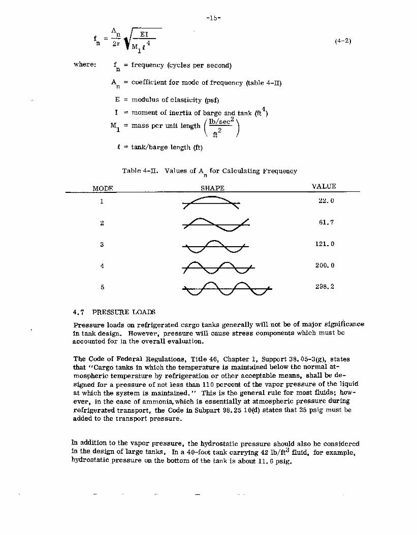
where: fn=
An=
E=1=
‘1 =
frequency(cyclespersecond)
coefficientformodeoffrequency(table4-II)
modulusofelasticity@sf)momentofinertiaofbargeandtank(ft4)
()lb/see%massperunitlength—ft2
tank/bargelength(ft)
(4-2)
Table4-II. ValuesofAnforCalculatingFrequency
MODE SHAPE VALUE
1 22.0/ \
2
3
4
5
4.7 PRESSURELOAm
/
Pressureloadsonrefrigeratedcargotsnksgenerallyintamkdesign.However,pressurewillcausestressaccountedfor intheoverallevaluation.
61.7
121.0
200.0
298.2
willnotbeofmajorsignificancecomponentswhichmustbe
TheCodeofFederalRegulations,Title46,Chapter1, Support38.05-3(g),statesthat“Cargotanksinwhichthetemperatureismaintainedbelowthenormalat-mospherictemperaturebyrefrigerationorotheracceptablemeans,shallbede-signedforapressureofnotlessthan110percentofthevaporpressureoftheliquidatwhichthesystemismaintained.” Thisisthegeneralruleformostfluids;how-ever,inthecaseofammoni~whichisessentiallyatatmosphericpressureduringrefrigeratedtransport,theCodeinSubpart98.2510(d)statesthat25psigmustbeaddedtothetransportpressure.
Inadditiontothevaporpressure,thehydrostaticpressureshouldalsobeconsideredinthe.designoflargetanks.Ina4O-foottankcarrying42lb/ft3fluid,forexample,hydrostaticpressureonthebottomofthetankisabout11.6psig.
— — .
’16-
4.8 TEMPERATUREANDTHERMALLOADSTemperatureandthermalloadsareimportantconsiderationsinthedesignofre-frigeratedtnks. Thermalloadswillbeofmajorsignificanceif thetankscarryverylowtemperature(lessthan-150°F)gasessuchasliquifiednaturalgases,oxygen,andnitrogen.Highlyspecializeddesignsarerequiredforverylowtempera-tureapplications,andextensiveheattransferanalysesarerequiredtopredictthermalloadings.Thermalloadsonlowtemperature(above-15O°F)appli-cationsarenbtgenerillyaproblemifthetanksareproperlyinsulatedandiftheyaregraduallycooledduringloadingoperations.
Thedesigntemperatureforlowtemperatureapplicationsis moreimportantasabasisformaterialselectionthanforpredictionofthermalstresses.Thedesignapproachtothermalstressesshouldbetominimizethemthroughproperinsulationandbyinstallationofspraynozzlesorotherdevicestocoolthetankgradually.“Lowtemperature”steelsaresuitedtotarkswithambienttemperaturesdownto-150°F. Liquif’iedgaseshavingtemperaturesbelow-150”willrequirespecialdesignsforinsulationanduseofcryogenicsteelsoraluminum.Moreinformationonmaterialselectionforlowtemperaturesisgiveninsection7.2.
ThedesignorservicetemperatureusedintheselectionoftankmaterialmaybedeterminedbythemethodspecifiedintheCodeofFederalRegulations,Title46,Chapter1, Subpart38.5-2(b):
“(b) Theservicetemperatureistheminimumtemperatureatwhichthecargois loadedand/ortransportedinthecargotank.However,theservicetemperatureshallinnocasebetakenhigherthangivenbythefollowingformula:t5=t -0.25(tw- t~)wwhere: ts = servicetemperature
tw~ boilingtemperatureofgasatnormalworkingpressureoftankbutnothigherthan+320F
tB= boilingtemperatureofagasatatmosphericpressure.‘‘
“(d) Heattransmissionstudies,whererequired,shallassumetheminimumambienttemperaturesof 00Fstillairand320Fstillwater,andmaximumambienttemperaturesof1150Fstillairand900Fstillwater.”
4.9 COLLISIONLOADSTheCodeofFederalRegulations’requirementforcollisionshockloadsof1.5gappearstobereasonable.Figure4-2showsthestoppingdistance,bargevelocity,andstoppingtimesfor1.5g,assumingconstantdeceleration.Theserelationshipswereobtainedfromtheelementarytheoryofdynamics.Thestoppingdistancesandtimesappeartobeconservati~’einlightofthelargemomentumofloadedbargesandtheamountofdeformationcommonlyexperiencedinbargecollisionsorgrounding.

-17-
18.0
16.0
14.0
4.0
2.0
0 0.1 0.2 0.3 0.4 0.5 ().6TimtoStop(seconds)
Figure4-2. BargeVelocityandDistancevs. TimeforConstantDecelerationof1.5g
4.10 LOADSONTANKS/BARGESDUETOSLAMMINGShip6lamming,ingeneral,isaproblemareawheremuchinvestigationisbeingperformed.Thepurposeof includingthisbriefsummaryoftheproblemisonlytoindicatethenatureoftheproblemtoreadersunfamiliarwiththeproblem.Slammingintheareaofthebowmaycauselargeareasofdeformation.Ifthedeformationisneara saddle,damagetothetankmayoccur. Evidenceisavailablewhichindicatesthats~ammingofbargescancausesignificantstructuraldamage.However,theproblemofsurfaceshipslamminghasyettobecompletelysolved.CertiinresultsJus~ul‘n‘hecaseofflatbottombarges,areavailable.
Thefollowingparagraphspretierdseveralofthelatesttheoreticaltreatmentsoftheslammingproblem.Fromtheresultspresentedinfigures4-3and4-4, itisclearthattheorydoesnotpredictveryexactvalues.Figure4-4shouldbeindicativeofthemagnitudesofslammingloadsthatwillactuallybeencountered.
Inarecentpaper12Verhagenpresentedthefollowingexpressionform~imumimpactpressure:
P =Cpvcmax a
where: p = densityofwater(’bzc’ )V= relativevelocityofcraftwithrespecttowater(ft/see)

-18-Ca= speedofsoundinair(ft/see)
C= anundefinedconstant
TakingthevalueofCas1, theresultingpressures,basedonrelativevelocitiesfromtheshipmotionsprogram(table4-III),arepresentedinfigure4-3.
Assumingapocketofairbetweentheboatandwater,Verhagen’sexactexpressionformaximumpressureis:
-’m&.—8 pa
where: -Y’P=oCa =B=M=P =
()g[:(;)2MP+M]“C:V12gasconstant Pa =atmosphericpressure ‘1 ‘speedofsoundinair PI =beamofboatmassofboat hl =
densityofwater t =o
densityofairwatervelocityattopressureatto
heightofpocketatto
timewhenairpocketis sealed
Thisyieldsvaluessimilartothoseoffigure4-4.
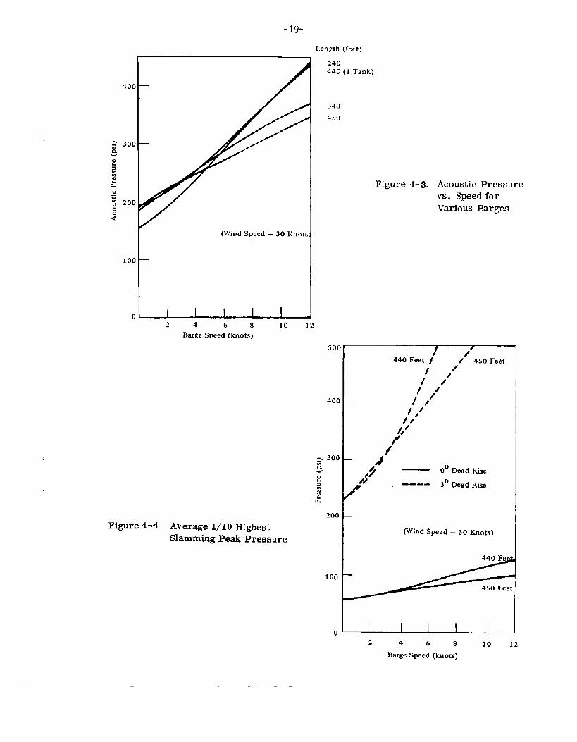
-19-
1(WindSpeed– 30 Kn[}ts
100
t
Length(feet)
240440 (1 Tank)
340450
2 4 6 8 10 12BargeSpeed(knots)
500
400
.= 300‘a
200Figure4-4 Average1/10Highest
SlammingPeakPressure
100
0
Figure4-3. AcousticPressurevs. SpeedforVariousBarges
/t
/44oFeetI J 45oFeet/’
1 /’/’0“/,//////“— A,9 — 0° DeadRise
/“- ---- 3°DeadRise
(WindSpeed– 30 Knots)
1 12 4 6 8 10 12
BsrgeSpeed(knots)

-20-Table4-llL Average1/1OHighestRelativeVelocityatSlammingStation
(3O-KnotWind)
BARGELENGTH(FEET)SPEED 440 450 340 240(knots) (ft/see) (ft/see) (ft/see) (ft/see)
o 12.416 12.307 11.970 9.8813 14.942 15*002 15.293 13*7996 19.176 17.563 18.572 18.6529 23.954 19.962 21.486 23.742,
12 28.128 22.082 23.945 *28.301
ACOUSTICPRESSURE(Pmm= pwaterx Cairx vfps)
BARGELENGTH(FEET)SPEED 440 450 340 240(kaOts) (Psi) (psi) (psi) (psi)
o 192.27 190.59 185.37 153.023 231.39 232.32 236.83 213:696 296.96 271.98 287.61 288.859 370.95 309.13 332.73 367.67
12 435.59 341.96 370.81 438.27
Chuang13presents,fortheimpactpressureof“a 20-inchx 26.5-inchrigidflatbottombody:‘‘
‘1.4t/T ~t
P(t)= 0.72V2 e sin—T
where: 7 is impactdurationtime
SinceChuangwasunabletoscalethistolargerbodies,andsinceVerhagenfeelsadependenceonV2isnotgoodforallweights,thisexpressionisnotconsideredfurther.
—
-21-
Chuangalsocalculatedtheimpactdurationtime.
B— = O.045secforabarge(beam= 100feet)2Ca
Inreference13Chuangpresentsaseriesofequationsforthemaximumpressureduetoslamming.
P = 4.5 V for0°deadrisehullmaxP = 4.11 V1”6for3”deadrisehullmsx
Theseareplottedinfigure4-6.
NotethatiftheconstantCinVerhagen’sacousticpressurewerechosenas0.29ratherthan1, Verhagen’sexpres~ionwouldbeidenticaltotheaboveexpressionfor0°deadrise.
Slammingstudiesdoneonadestroyerindicatethattheactualslammingpressuresatthebowofabarge(wherethereisprobablysomedeadriseangle)probablyfallinthersngebetweenthesolidanddottedcurvesoffigure4-6.
Sincetestdatainthisareaisquitesparse,furtherworkonbargeslammingshouldbeundertaken.Anoutlineforanexperimentalprogramforthiseffortis inAppendixD.
-22-Section5
STRUCTURALDESIGN/ANALYSISOFTANKBARGES
Thestructuraldesignprocessforlargetanksmaybebrokendownintofourstraight-forwardstepsoncethecapacityandtankloadingshavebeenestablished.Thisprocessis essentiallythatwhichispresentlyusedforsmallerriverbargetanksanditmaybesummarizedasfollows:
1.
2*
3.
4.
Frompreviouslydeterminedtankdiameter,tanklength,pressure,weightanddynamicloadings,determinethebasictankconfiguration,i.e. , aneconomicalcombinationoftankwallthickness,numberofsupports,sndsupportspacing.Determineareaandmomentofinertiarequirementsforstiffenersandthick-nessofwearplatesduetoweightanddynamicreactions.Determinesupprtreactionforthegroundedconditioninthecaseofriverbargesand/orsaggingandhogginginthecaseofoceanbarges.Checklocalstressesintheareaofsaddlesduetogroundingand/orsagging/hoggingreactions.
If, atanypointinthedesign,thestressesexceedallowablelimits,scantlingsmaybeincreasedandthedesigncontinuedfromthatpoint.
Inthecaseofoceanbarges,thedesignershouldalsodetermineifthealternatingstressintensityisbelowtheendurancelimitforthepredictednumberofcyclesofhoggingsndsagging.
Indeterminingthebasicsizeofoceantank/barges,thefundamentalbendingfrequencyofthetsnk/bargestructureshouldbecalculatedaccordingtotheproceduregiveninsection4.6. Thefundamentalfrequencyofthecombinedbarge/tankstructureshouldbegreaterthantheforcingfrequencyofthewaves.ForcingfrequencymaybeestimatedusingthemethodgiveninAppendixA.
5.1 EXISTINGDESIGN/ANALYSISPROCEDURESTheU.S.CoastGuard2sndtheAmericanBureauofShipping6bothfurnishguidanceonthedesign/analysisoftankbarges.T~seguidelinesuse,asabasisfordeterminingstressesatsaddles,themethodof Zick. BothsourcesalsorefertothemethodofBrownellandYoung(reference14)whichis essentiallythesameasZick’smethod.Tankbargedesigners,almostwithoutexception,usetheCoastGuardproceduretoanalyzestressesintanks.Theauthor,inreviewingtheliterature,didnotuncoveranyotherdirectlyappl~5ablesimplemethodofanalyzingtankstressesintheareaofsaddlesupports.Rffren discussestheproblemofringstiffenersinmoredetailthanZickorBrownellandYoung,andthediscrepancieswhichoccurappeartobeminor.
TheCoastGuardandseveraldesignagentsutilizeacomputerprogramstocalculatesaddlereactionsofindependenttqnkbargesinthegroundedcondition.Usinganitera-tiveprocess,theprogramdeterminesthetotal(tankplusbarge)momentandthetankmomentateachsaddle,togetherwiththecorrespondingverticalreactions.(Theiterativeprocessmayalsobeperformedwiththeaidofadeskcalculator.) With

-23-
thetankmomentsandverticalreactionforcesknown,thestressesduetolongitudinalbending,circumferentialbending,directcompression,andtangentialshearmaybedeterminedusingthemethodofZick.ThestressesmaythenbecomparedtodesignallowablestressesasrecommendedbyZickorspecifiedintheCodeofFederalRemulations.
Anumericalmethodfordeterminingstressesinshellsofrevolutionsubjectedtoaxi-symmatricornon-symmetricreasure,bandloads,ringforces,andringmomentshasbeenpublishedbyKalnins.% ThismethodhasbeenprogramedforcomputationontheUNIVAC1107computer(reference16). Duringthestudythisprogramwasutilizedtoobtainacomprehendivestressdistributionintheareaofthesaddle.Stressesweracomputedontheinside,outside,andmid-surfaceofthetankwall.AdiscussionoftheanalysisandacomparisonwithresultsduetotheZickmethodaregiveninsection6.
Design/analysisofocean-goingbargessubjectedtosaggingandhoggingmaybeap-proachedinamannersimilartotheprocedureforgroundingcalculations.Specificcriteriaforcomparingalternatingsaggingsndhoggingstressestodesignallowable,basedonfatiguetheory,donotappeartoexist,nordoesaprecedentexistforincludingdynamicloadsinafatigueevaluation.Anapproachtothisproblemis discussedinsections4.5and6.4.
Experienceindesign/analysisofoceanbargesappearstobequitelimited.Inarecentsurveyoftheindustry(reference17),onlyonedesignforindependent,cylindricalocean-goingtank/bargeswasidentifieiLThisdesignwasforabargeofapproximately20,000tons,withtwotanks,eachabout30feetindiameterand300feetlong.Thetwotankshadoriginallybeendesignedtobecontinuouswithmultiplesupports.How-ever,thisdesignresultedinnegative(lift-off)forcesinthesaggingandhogginganalysisandthedesignwasmodifiedbyincreasingthenumberoftankstofour,eachsupportedononlytwosupports.
Asecondocean-goingtank/bargeconsistingofthreeintersectingcylinderswasre-portedtobeintheconstructionstagebutdesigndetailswerenotavailable.
&2 RATIONALEFORDETERM~NGT~ WALLT~CKNESSANDNUMBERANDSPACINGOFSUPPORTS
InEection4thetankandsaddleloadsduetotankandcargoweightaredeterminedfortanks200,300and400feetlongandwithconfigurationscontainingfrom2to11saddlesupports.Uniformcircularcross-section,uniformlyspacedsupports,hemis-phericalendenclosures,andanoveralllength/diameterratioof10wereassumedinthecalculationoftheseloads.Amethodwhichisanalogoustathatof Zickwasemployedtodeterminetherequiredtankthickness.Largetanksshouldbedesignedsothatthetankisreinforcedbycircularstiffeningringsplacedeitherdirectlyoveroradjacenttothesupports.5.2.1 CALCULATIONOFSTRESSES– Becauseofthelowinternalpressureassociatedwithrefrigeratedcargoes,thecircumferentialtensilestressinthetankisnotnecessarilythebasisfordeterminingther~uiredtankthickness.ThisisadeparturefromtheproblemwhichZickinvestigated.Themaximumcircumferentialtensilestressoccursatthebottomofthetankandis causedbyuniformintermilpressureplushydrostaticpressureduetotheweightofliquidenclosed.From

ClassicalMembraneisgivenby
(uh)~=
-24-ShellTheory,themaximumcircumferential(hoop)tensilestress
.mt (5-1)
whereP*is themaximuminternalpressure.Itisalsonecessarytoexamineotherprimarytankstressessothatthecriticalstressconditioncanbedetermined.BasedonClassicalBeamTheory,thelongitudinalbendingstressdistributioninthetank(at6’=O,180°asdefinedinfigure6-1)isgivenby -
(5-2)
Substitutionof themaximumbendingmoment,M*,whichoccursatthesupports,intoeq. 5-2yields
Thetransverseshearing
us(x)= ~7rrt
(5-3)m~t
stress distributioninthetank(atO=90°) isgivenby
(5-4)
Substitutionofthemaximumshearforce,V*,whichagainoccursatthesupports,intoeq. 5-4yields
(5-5)
5.2.2 ALLOWABLESTRESSLIMITS—Zickplacesthefollowinglimitsonprimarytankstresses:
a. oncircumferentialstress,theallowableworkingstressforthematerial.b. Onlongitudinaltensilestress,theallowableworkingstress.c. Onlongitudinalcompressivestress,thesmallerofone-halfyieldstressor
thevaluegivenby
(5-6)
whichaccordingtoZickis “basedupontheacceptedformulaforbucklingofshortsteelcylindricalcolumns.7‘
d. Onshear stress, 80percentoftheallowableworkingstress.
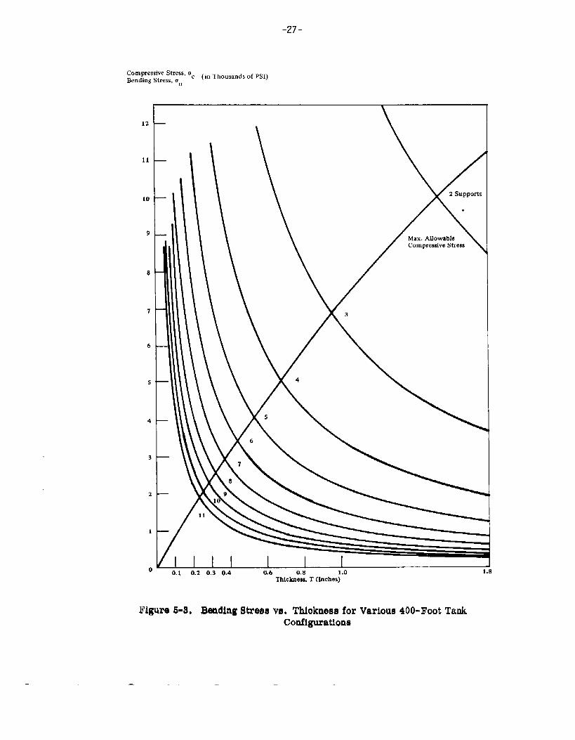
5.2.3 DETERMINATIONOFCONTROLLINGSTRESSMAGNITUDE- Basedonthelimitsonprimarytankstresses(section5.2.2), itwasfoundthatthelongitudinalcompressivestressis criticalwhendeterminingtankthickness.Figures5-1,5-2,and5-3showthevariationofmaximumlongitudinalbindingstresswiththicknessforeachofthetendifferentsupportconditionsfora 200-,300-,and400-foottankre-spectively.Superimposedoneachgraphis thevariationofallowablelongitudinalcompressivestresswiththickness(accordingb eq.5-6).
Withthehelpoftheseparametriccurves,typicaldesignsfora200-foot,300-foot,and400-foottankmaybedetermined.

-25-
&md&&::::; “C (InThouumhofHI)
12
11
10
9
8
7
6
5
4
3
1
1
0
—
—
—
—
L
0.1 0.2 0.3 0.4 0.5 0.6 0.7 0.8 0.9Thickneu,t (lrmf@
Figure5-1, EendinEStreamVH.Thickn8ssforVarious200-FootTankConfigurations

CompressiveStress,aBendingStress,U. c (inThousandsofPSI)
12
11
10
9
8
7
6
5
4
3
2
1
0
Mm.AllowableCompressiveStress
\ 2SurmOrtu
I I I I I I 1 1
0.1 0.3 0.5 0.7 0.9 1.1 1,3 1.5 1.7 1.sThickness,t (Inches)
Figure5-2. BendingStressvs. ThicknessforVarious300-FootTankConfigurations
-27-
&#&s&~r~’ ‘c (inThousandsofPSI)‘0
12
11
10
9
8
7
6
5
4
3
1
1I
10U.i WA u.> U.* u. o w.0 ,.” 9
Thickness,T(Inches)
Figure6-S, BandingStrefmVU,Thiokne~sforVarious400-FootTankConfigurations
— —

-28-
5.2.4 DYNAMICU3ADS– Dynamicloadfactorsduetoshipmotions(heaving,pitching,etc.)aregiveninsection4. Thesefactorsreflectthemostseverecombina-tionofshipmotions.Toaccountforthesedynamicloads,thestressesinthetankduetocargoandtankweightmustbemultipliedbyoneplusthedynamicloadfactor.
Theuniforminternalpressureforwhichthetanksmustbedesignedisdiscussedinsection4.7.Thispressurecontributestauniformlongitudinaltensilestressinthetanks.Thevalueofthistensilestressisafunctionofthetankradius.Tocalculatethemaximumlongitudinalcompressivestresslevelitisnecessarytosubtractthisuniformtensilestressfromthebendingstress.
5.2.5 CHOICEOFSUPPORTCONFIGURATIONS—Afive-supportconfigurationwasarbitrarilyselectedasrepresentativeofthin-walledtankswithminimumsup-ports. ThisselectionconformswiththeAmericanBureauofShippingregulationswhichstatethatdistancesbetweensupportsshouldnotexceedtwicethetankdiameter.
Therequiredtankthicknessfora200-foot,300-foot,and400-foottankwasthendeterminedforafive-supportconfigurationbyadjustingthebendingstresscurvesandlocatingtheirintersectionwiththeallowablelongitudinalcompressivestresscurve;theintersectionspecifiestheminimumthicknessrequiredtomeetthestresslimit.
5.2.6 REQUIREDTHICKNESS—Thefollowingtatithicknessesweredeterminedforafive-supportconfiguration:
Configuration Thicknessa. 2oo-foottank O.2inchesb. 3Oo-foottank 0.4inchesc. 4oo-foottank O.65inches
Standardfabricationpracticefor20-footdiametertankscallsforawallthicknessof5/16inchorgreater.Itwasthereforearbitrarilydecidedthatforthe200-foottanktheminimumwallthicknesswouldbeincreasedto5/16inch,althoughtheoreticallythethicknesscouldhavebeenO.2inches.Utilizingthisdesign,foursupportswouldprovidesufficientstrength.
5.2.7 DETERMINATIONOFSTIFFENERSIZE– Designoftheringstiffenerswasbasedontheanalysisof180°arbitrarysaddlesupports(AppendixB). Thecir-cumferentialstressesinthestiffeneraregivenby
(’Q -0.48~ 0.043~ r.— -A I/c (5-7)
compress.+0.158Q +0.043~r
@o)tensile= A I/c
Zicksetsthefollowinglimitsonthecircumferentialstiffenerstress:a. orIb. on
.—
compressivestress,one-halfyieldstress;tensilestress,allowableworkingstress.
and

-29-
Atthispoint,itwasnecessaryh designateatypicalmaterialinordertadeterminetherequiredstiffenerstrength(basedonthepreviousstresslimits).Forthispurpose,carbonmanganesesiliconsteel,A516Gr65,waschosen.Itsmaterialstrengthpropertiesare65,000psiultimatestress,35,000psiyieldstress,and16,250psiallowableworkingstress.Knowingthelimitsoncircumferentialstressinthestiffener,therequiredcross-sectionalareaandsectionmodulusaredeterminedfromeq. 5-7.
Asummaryofthetankgeometryanddesignstressversusallowablestressesispresentedintable5-Iforeachofthethreetanksizesstudied.Figure5-4showsthethreerepresentativetankdesignsdrawntothesamescale.Thetankconfigurationsarerepresentativeofminimumrequirementsforthicknessandnumberofsupports.Flexibletanksareconsideredtobedesirabletoprevent“liftoff”ingroundingandsagging/hoggingconditions.
~ 200’u u u u 120”
K- 612”+(a) ‘
180”
(b)
~ 400’r
t-- “’”~ “’”--l 240”
Figure5-4.
(c)
ThreeRepresentativeTankDesigns

-30-
Table5-L Summaryof TankCmrfigurationsSelectedforAnalysisof GroundingandSagging/Hogging
OVERALLTANKLENGTH200FT 300FT 400FT
TankRadiusNo.ofSupportsSupportSpacing~lidthofSupportsTankThicknessStiffenerSect.Mod.StiffenerCross-Seet. Area
Circum.TankStressDesignAllowable
Long. Tens.TankStressDesignAllowable
Long. !Xnnp.TankStressDesignAllowable
120in.4
612in.12in.
5/16in.390in.3
170in.2
6,900psi16,250
5,60016,250
1,7604,730
TransverseShearTankStressDesign 4,350Allowable 13,000
Circ.Tens.Stiff.StressDesign 13,100Allowable 16,250
Circ.Comp.Stiff.StressDesign 16,900Allowable 17,500
180in,.5
725in.18in..4 in.
1875in.3
450in.2
10,600psi16,250
6,87016,250
2,3704,130
6,89013,000
13,30016,250
17,30017,500
240in.5
968in.25in.
.65in.6670in.3
1000in.2
11,100psi16,250
7,60016,250
3,9104,920
8,55013,000
13,30016,250
18,500*17,500
*Exceedsallowableinactualdesignstiffenersizewouldbeincreased.

-31-
5.3 DESI~,NF(3RBUCKLINGInbetweenstiffeners,thecylindricalshellis subjectedtolargecompressivebendingstressduetothenatureoftheloading.Considerationmustbegiven,therefore,tothepossibilityoftheshellbuckling.Thecriticalcompressivestress,u , hasbeencommonlyacceptedasbeing1.3timesthecompressivebucklingstr& (duetouniform
18 Fl~gge’sresultwasaxialcompression).SuchavaluewasobtainedbyFlfigge.foraparticularshellandbucklegeometryandisnotgenerallytrue,asis showninreference19. Theresultsofthisstudyshowedthatthecriticiiaxialcompressivestressduetobendingisnotmorethan10percentgreaterthanthecriticalstressforalongshellunderuniformaxialcompression,unlesstheshellisextremelyshort(lL/r< 0.15).Forrelativelylargelength-to-radiusratios(L/r)andradii-to-thicknessratios(r/t), reference19showsthat:
“Cr‘e) ; (5-8)
Theseresultsshowthatlinearbucklingofacircularcylindricalshellduetoasymmetric(non-uniform)axialcompressivestressdistributionwillalwaysoccurataloadlevelwherethemaximumlocalaxialcompressivestressequalstheuniformaxialcompressivestressforbuckling.
Sincethepresentstudyisdirectedtoverythincylindricalshells,initialdeviationfromtheidealcylindricalsurfaceshouldbeconsidered.(Thesemaycausebucklinatastresslevellowerthanthetheoreticalelasticbucklingstress.) Timoshenko2%presentsanempiricalformulaforcalculatingtheultimatestrengthofcylindricalshellsunderaxialcompressionwhichconsiderstheeffectofinitialimperfections.Thisformulaisgivenas:
‘Ult [1t-7 r0.6 ~-10 ~E
1+0.004~uYP
(5-9)
whereu istheyieldstrengthofthematerial.YP
Considera400-foottankwitha 20-footradius,m 80-footsp~ betweensupports,andashellthicknessofO.65inch.Applyingeq. 5-8andeq.5-9yieldsthefollowing
Assume E = 30x 106psi, v= O.3,andtr =35,000psiYPTheoreticalelasticbucklingis:
30x 106 0.65
“r= [~(’:@d“2= “4“200psi
—

-32-
FromTimoshenko(reference20):
= 30X106‘Ult
“Ult= lo,700psi
-7 ,240—-lo ()G5
1+.004()
30x 10635X103
Othertest results, givenin reference21,haveyieldedresultssimilartothoseob-tainedbyTimoshenko.Figure5-5,obtainedfromreference21,showsanondimen-sionalplotofthetheoreticalelasticbucklingcurveandanempiricalcurvebasedontestdata.AscanbBseeninfigure5-5,cylinderswithaslendernessparameter,
hr ofO.064orlesscanbestressedtotheiryieldstresswithoutbucklingE ~’
whereascylinderswithlargerslendernessparameterswillbuckleatlowerstresses.
1.0
0.9
0.8
0.7
0.6
0.5
0.4
0.3
0.2
0.1
0
;y,::: y+
~- O.16+0.20\ YPt
‘YP
\(Experimental)r
\
\
\
I I 1 I I I I I 10.1 0.2 0.3 0.4 0.5 0.6 0.7 0.S 0.9 1.0
aNondimensionalSlendernessParameter~ ~Et
Figure5-5. NondimensionalBucklingCurveforCircularTubesinCompression
—. -. .— — —

-33-
Applyingthiscurvetoourdesigncase,weobtain:
h L . 357000Psi ~.~oin.Et 6 0.65in. = 0.43
30x 10 psi
Andsince
Fcr E t—=.16—– r‘YP ‘YP
then
u = 13,000psiCr
Timoshenko’sresultsappearh givealowervalueofcriticalbucklingstressforthiscaseand,therefore,hisistherecommendedproceduretofollow.Ontheotherhand,applyingZick’scriticalbucklingstressformulatoourdesigncaseyieldsacriticalcompressivestressof4,920psi. Thisnumberappearstobehalfof thevaluegivenbyTirnoshenko’sempiricalequation.
5.4 REACTIONLOADSDUETOGROUNDINGSAGGINGANDHOGGINGInsection5.2therationaleforselectingwallthicknessandthenumberandspacingofsupportsforhypotheticaltanks200,300,and400feetlongwaspresented.Inthissection,thehypotheticaldesign/analysisprocedurewillbecontinued.
Itwasconcludedinsection4.3thatgroundingisthemostsevereconditionforriverbargesandthatsaggingandhoggingloadsaremostcriticalinoceanbarges(section4.4). However,inordertoanalyzetheseconditions,theW bargestructuremustfirstbeanalyzedasawhole.Itwasnecessarythereforetopreparepreliminarydesignsof bargestothepoint,whereweight,buoyancyandoverallbendingstrengthmaybedetermined.Forexpediency,the200-foottankandacorrespondingbargewereselectedforthegroundingcalculations,andthe400-foottankandcorrespondingbargewereselectedforthesagging/hogginganalysis.BothconditionswereanalyzedusingtheCoastGuardprocedureaidedbyadeskcalculator.
5.4.1 CONFIG~ATIONANDCHARACT’EHSTICSOFBARGES– Thegeneralcon-figurationandcharacteristicsofriverandoceanbargesareshowninfigures5-6and5-7.Typicalsectionalviewsforthepurposeofdeterminingbendingstrengthareshowninfigures5-8and5-9.Thetankdimensionsareshowninfigure5-10.
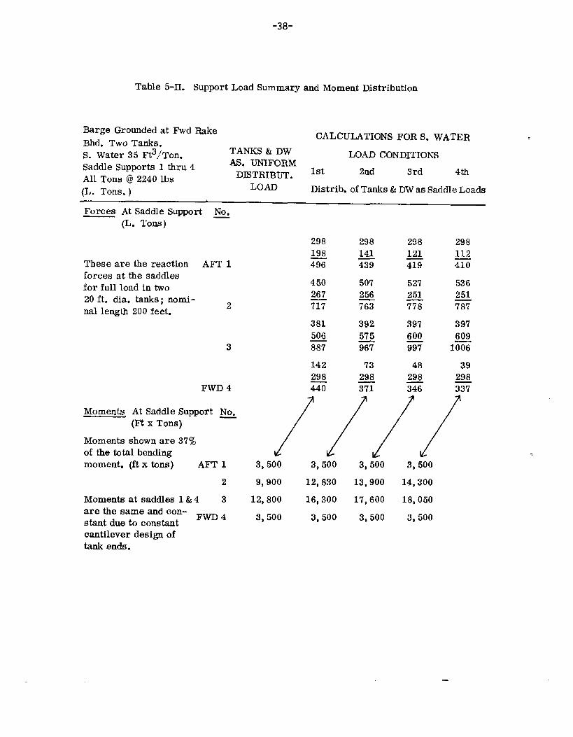
5.4.2 RESULTSOFGROUNDINGCALCULATION—The200-foottankconfiguration,loadingdiagram,shearcurve,andmomentcurvesareshowninfigure5-11.Asum-maryofforcesandmomentsactingonthesaddlesisgivenintable5-II.

5.4.3 RESULTSOFgiveloading,shear,
-34-
SAGGING/HOGGINGCALCULATION– Figures5-12and5-13andmomentcurvesforsaggingandhoggingofthe400-foottank.
Tables5-IIIand5-IVsummarizetheforcesandmomentsac~ingatthesaddles.
‘[ I 1I I )1I\% I i
I .==~===.–.–_=* ======~====== ==<==<’III
II
I ‘]II /1
I “k.-.— — ———— _ _____ __ ———— Y i–-’ ILOA– 270’
MlLoadDisplacement–3,000LTons
//”––––––––– –––-–-–-–– ––––---.\
———— ——
Figure5-6. ConfigurationofaTypicalRiverBarge
T (jT’,/ ‘..\1’ 1
1’96’ ‘\, ,/’-.-L.—-—L.—----- ----- ---- .—-———---- ------ -- .-—-—————---...—.., ...-—..——.————— .—,----- .---- ----- ------ —-—-————-——------ —---- ----- --- —-. “%
/ \\1’
L 1
iI!, ,;‘.FullLoadDisplacement–21,050L.Tons
\—--———IL / ;---- \\38’
+ ,~-’~--
\.18’ .~’-90’4 LOA–459’ ——..
LWL-450
Figure5-7. Configurationofa TypicalOcean-GoingTankBarge

-35-
1
t’
~,\\
I.—+—.
Ek 1
[Eu
u LLl IA w u LLlul IA Lu0000 00000
BargeStructure:Momentof Inertia: 39,850in.?x ft2SectionModulus: 7,520in.z ft
Figure5-b. ‘lypjc~]RiverBargeSectionalViewI
+.— ——
I
BargeStruct~e:MomentofInertia: 732,813in.2xft2SectionModulw: 30,933in.2xft
Figure5-9. T~icalOcean-Going”BargeSectionalView
—

’36-
OCEANTANK/BARGEEquivalentLength
3884”- ——————+
.
Saddle L- ’06, ---L-- ,O.,,–-l- ,..6,+ ,0.,,-’lSpucing .—.—— .— LOA400’ /
MomentofInertiaforOneTank: I=196,036in.2xft2WeightTWOTankx 1260L.Tons
RIVERTANK/BARGE
MomentofInertiaforOneTank I=11,808in.2xft2WeightTwoTank% 260L.Tons
#
—
Figure5-10. TypicalTankCharacteristicsandSaddleSupports

-37-
WeightCuwe16128404812162024
400300200100
0100200300400500600‘looSoo900
40,000
30,000
20,000
10,000
Stern 270’
I 34.510
Figure5-11.
i 2 j 4NumberofSaddles
TypicalLoading,Shear, andMomentaGroundedRiverBarge
IGroundingForce
.r50’—
Stem
— 5Q’—
Diagramsfor
-38-
Table5-II. SupportLoadSummaryandMomentDistribution
BargeGroundedatFwdRake CALCULATIONSFORS.WATERBhd.TwoTanks.S. Water35Ft3/Ton. TANKS&13W LOADCONDITIONSSaddleSupportsI thru4 AS.UNIFORM
13JSTRIBUT.1st 2nd 3rd 4thAllTons@2240lbs(L. Tons.) LOAD Distrib.ofTanks&DWasSaddleLoads
ForcesAtSaddleSupportNo.(L. Tons) —
ThesearethereactionAFT1forcesatthesaddlesforfullloadintwo20ft. dia.tanks;nomi- 2nallength200feet.
3
FWD4
MomentsAtSaddleSupport~(mx Tons)
Momentsshownare37%ofthetotalbendingmoment.(ftx tons) AFT1
2Momentsatsaddles1&4 3arethesameandcon- FWD4stantduetoconstant
450267m381506m142298m
298141G5072563392y&96773
2981215527251m397600G48
298G
298112G536251G397609
lG39
298G
3,500 3,500 3,500 3,5009,900 12,83013,900 14,300
12,800 16,300 17,600 18,0503,500 3,500 3,500 3,500
cantileverdesignoftankendg.

-39-
i80 DisplacementCUWG60 WeightCurve
40---
\T20 4691
‘~ * &3.24---
b DifferenceCuWe $ 6 ; ‘%.~~j~”;- ! Id1% I ~ +-4’‘arge
1s rm-! 1●“,-0
0A.P
5
10
15
20--
/(,ShemCurve
5 6 ‘1 8 9PP.
1’285,592
99,957
h
1 1 I 1
[ #1+ 80.6’+80.6’+ : 80!’6’
8 9Saddle #2
80.6 :.;.#3 #4 *<
Binge --l
Figure5-12. TypicalLoading,Shear,andMomentDiagramsforanOcean-~i~TankBarge@aggingCondition)
Tanks
-. —

-40-
100L DisplacementCurve80-60-
z& ~o 1-~ 20-:
0
-‘%A.P.41 2 3
L -Saddle #l” #2.-——..——.- ..-—-—~EquivalentLength388.4Feet
18t 1600.1
200,00‘T~8,447
~10F.P.
\
E LL-‘,65,741 65,956
:mG.- 56,>u 34,803t? 19.161 , ~I~–-~
,,:--- ...+...8 ..74‘0“p”#3IiquivalenlLength386.4Feet
Figure5-13. TypicalLoatig,Shear,andMomentDiagramsforanOcean-GoingTankBarge (HoggingCondition)
——-.

-41-
Table5-III.SupportLoadandMomentSummary– SaggingCondition
TwoTanksS.Water35Ft3/Ton.
CALCULATIONSFORS.WATERLOADCONDITIONS
SaddleSupports:1thru5. TANKS&DW 1st 2nd 3rd 4thAllTons@2240Lbs AS.UNIFORM(L. Tons) LOAD Distrib.ofTanks&DWasSaddleLoads
ForcesAtSaddleSupportNo.(L. Tons)
16553198
ThesearethereactionAFT1forcesatthesaddlesforfullloadintwo40-ftDtanks,nominallength400ft. 2
3
4
FW135
MomentsAtSaddleSupportNo.(FtXTonS) —
Momentsshownare35%ofthetotalbendingmo-ments(ftx tons) AFT1
2Momentsforsupports 31&5areconstantduetocantileverdesignat 4endsoftanks. AFT5
4853844
238532291657165733142385844
3229319816554853
/
165528874542115522643419177817783556226411553419288716554542
1655300446591038230833461734173434682308103833463004
23,501 23,501 23,50171,400 46,329 55,697
100,000 65,934 78,86171,400 46,329 55,69723,501 23,501 23,501

-42-
Table5-IV.SupportLoadandMomentSummary—HoggingCondition
TwoTanksS. Water35Ft3/Ton. LOADCONDITIONSSaddleSupports:1thru5. TANKS&DW 1st 2ndAllTons@2240Lbs AS.UNIFORM 3rd 4th(L. Tons) LOAD Distrib.ofTanks&DWasSaddleForces
ForcesAtSaddleSupportNo.(L. Tons)
16551816
ThesearethereactionAFT1 347’1forcesatthesaddlesforfullloadintwo40-ft.D. 2226tanks,nominallength 1699400ft. 2 3925
23432243468616992226392518161655
FWD5 3471
16552109G193318093742223322334466180919333742210916553764
MomentsAtSaddleSupport~/
//
1655188635412156175239082290~458017522156390818861655E
/
Momentsshownare35% /ofthetotalbendingmo-ments. AFT1 23,501
2 40,000Momentsforsupprts 3 65,9561&5areconstantduetocantileverdesignat 4 40,000endsof tanks. FWD5 23,501
23,501 23,50126,405 34,38243,456 56,10226,405 34,38223,501 23,501

-43-
Section6
EVALUATIONOFSTRESSESINEXISTINGANDPROJECTEDDESIGNS
Insection5therationalefordesignoftypicalindependenttanksforriverandoceanbargeapplicationswasdiscussed.TWOhypotheticaldesigns,basedonasimplifieddesign/analysisapproach,wereselectedformoredetailedinvestigationofstressesinthetanks.
Theobjectivesofworkdescribedinthissectionaretoevaluatethesimplifieddesign/analysistechniqueswithrespecttotheaccuracyofpredictingstressesduetocriticalloadsandtoexaminethevalidityofanindividualstreBscriteriaapproach.Toac-complishthesegoals,therepresentativedesignsweresubjectedtocomputeranalysisusinglinear,thinshelltheoryapplicabletonon-symmetricallyloadedshellsofrevolution.Acomputerprogramwasusedforthisanalysis.Atypicalstructuremodelusedforthecomputeranalysisisshowninfigure6-1. Themodelrepresentsa theoreticalconfigurationandisnotintendedasapracticalconfigurationforpurposes
t----x UniformAx3alForceduetoUniform
ment
SaddleReactionLoadonRing
Figure6-1. TypicalStructuralModelforComputerAnalysis
—
-44-
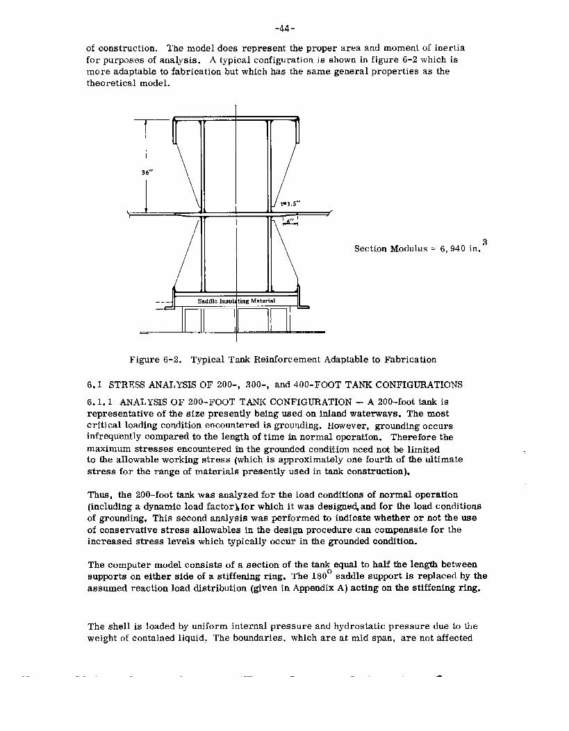
ofconstruction.Themodeldoesrepresenttheproperareaandmomentof inertiaforpurposesofanalysis.Atypicalconfigurationisshowninfigure6-2whichismoreadaptabletofabricationbutwhichhasthesamegeneralpropertiesasthetheoreticalmodel.
T—36’”
SectionMoclulusE:6,940in.3
-., - SaddIeIn8ulatingMaterial
Figure6-2. TypicalTankReinforcementAdaptabletoFabrication
6.1 STRESSANALYSISOF200-,300-,and400-FOOTTANKCONFIGURATIONS6.1.1 ANALYSISOF200-FOOTTANKCONFIGURATION– A200-foottankisrepresentativeofthesizepresentlybeingusedoninlandwaterways.Themostcriticalloadingconditionencounteredisgrounding.However,groundingoccursinfrequentlycomparedtothelengthoftirneinnormaloperation.Thereforethemaximumstressesencounteredinthegroundedconditionneednotbelimitedtotheallowableworkingstress(whichisapproximatelyonefourthofthedtimatestressfortherangeofmaterialspresentlyusedintaukconstruction),
Thus,the200-foottankwasanalyzedfortheloadconditionsofno~maloperation(includingadynamicloadfactor~forwhichitwasdesignedandfortheloadconditionsofgrounding.Thissecondanalysiswasperformedtoindicatewhetherornottheuseofconservativestressallowableinthedesignprocedurecancompensatefortheincreasedstresslevelswhichtypicallyoccurinthegroundedcondition.
Thecomputermodelconsistsofasectionofthetankequaltohalfthelengthbetweensup~rtsoneithersideofastiffeningring.The180°saddlesupportis replacedbytheassumedreactionloaddistribution(giveninAppendixA)actingonthestiffeningring.
Theshellis loadedbyuniforminternalpressureandhydrostaticpressureduetotheweightofcontainedliquid,Theboundaries,whichareatmidspan,arenotaffected
—

-45-
bythelocalbendingstressatthestiffeningrings(supports).Therefore,amembranestateofstresswasassumedinthetankattheselocations.Ithasbeenshown,18however,thatthismembranestateofstresscanbeconservativelydeterminedbyabeamanalogy,i.e. , analysisofthecylindricaltankandliquidasabeamsupportingadistributedload.Thelongitudinalnormalstressdistributionvariesaboutthecir-cumferenceasthecos 0.Thenetresultofthisstressis thelongitudinalbendingmoment.Thein-planeshearstressdistributionvariesaboutthecircumferenceasthesin0.Thenetresultofthisstressis thetransverseshearforce.Throughthebeamanalogy,theappropriatestressboundaryconditionsatmidspanforthecomp-uter modelareobtained.
Themostcriticalstressregion(andalsotheregionmostcrudelyanalyzedinpre-viouswork)isatthestiffeningringsoverthesupports.
Highlocalbendingstressesshouldbeexpectedinthisregionbecauseofthehighcon-centrationofloadappliedtothetankbythesupportsandthelargechangeinstiffnessfromthetanktothestiffeningring.Toreducethislocalstress,thetankwallwasreinforcedonbothsidesofthestiffener;atthestiffener,thethicknessofthetankwastripled.~hethicknesswasthentaperedoverasix-inchlengthtothenormaltankthickness.Thesizeandshapeofthereinforcementarebasedonasmallparametricstudyperformedonthe400-foottankmodelwhichispresentedundertheanalysisofthe400-foottank.
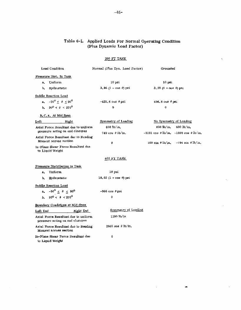
Thetwoloadconditionsanalyzedareshownintable6-I. Forthegroundingcondition,theloaddistributionisnotsymmetric,therefore,onlythemostseverelyloadedsup-portwasanalyzed.Fornormaloperation,eachsupportis loadedapproximatelythesameamountandtheassumptionofloadsymmetryabouteachsupportwasmadeinthedeterminationofloads.Therefore,theanalysisappliestoallof thesupportsfortheconditionofnormaloperation.
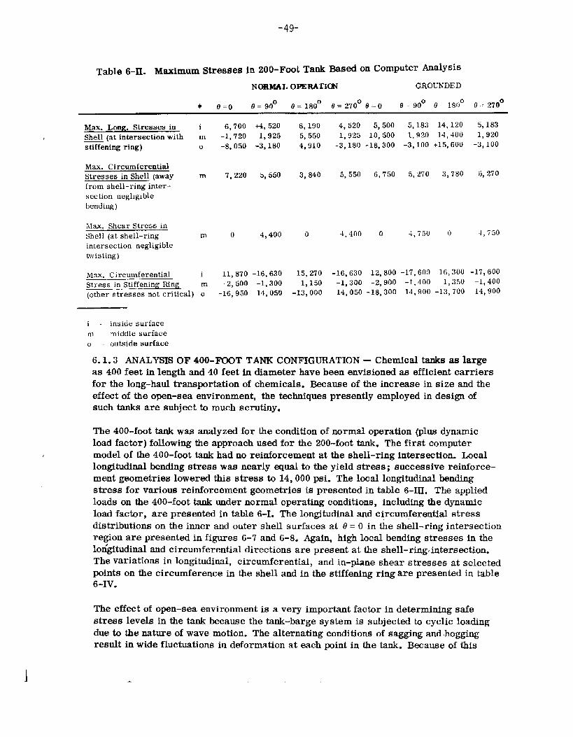
Thelongitudinalandcircumferentialstressdistributionsontheinnerandoutershellsurfacesat@=O,intheregionofthestiffeningring(support),arepresentedinfigures6-3through6-6forthenormalandgroundedconditions.Highlocalbendingstressesattheshell-stiffenerintersectionarepresentinboththelongitudinalandcircumferentialdirections.Table6-11liststhevariationoflongitudinalnormal,circumferentialnormal,andin-planeshearstressatselectedpointsaroundthecircumferenceintheshellandinthestiffeningringforbothloadconditions.Thecomparisonofresultsofthesimplifieddesign/analysistechniqueandthemoresophisticatedcomputerapproachisgiveninsection6-2.
6.1.2 ANALYSISOF300-FOOTTANKCONFIGURATION—The300-foottankalsowasanalyzedfortheconditionofnormaloperation(plusdynamicloadfactor).Theanalyticprocedureis thesameasthatemployedforthe200-foottank.Thestressdistributionandlocationsofcriticalareasaresimilartothoseobtainedforthe200-foottank.Becausenoadditionalconclusionscanbedrawnfromtheanalysis,thedetailsareomitted.
-46-
LoadCondition
Table6-L AppliedLoadsForNormalOperatingCondition(PlusDywmicLoadFactor)
200I?TTANK
PressureDist. InTanka. Uniformb. Hydrostatic
Normal(PlusI)yn.LoadFactor)
10psi3.96 (1+cos 0)psi
SaddleReactionLoada. -90°~ e ~90° -427.6COS 8 I)d
b. 900<0 <270° 0
B.C.s. AtMidSpan
Left Right Symmetryof Loading
AxialForceResultantdueto uniform 600lb/in.pressureactingonendclosures 749cos @lb/in.
AxialForceResultantduetoBendingMomentacrosssection o
In-PlaneShearForceResulkmtduetoLiquidWeight
PressureDistributioninTanka. Uniformb. Hydrostatic
SaddleReactionLoada. -90°~ e ~ 900b. 90°<0 <270°
400I?TTANK
10pai
10.03(1+cos 0)psi
-966cos19psio
Grounded
10psi3.23(1+00SO)psi
456.8cosOpsio
BoundaryConditionsatMid-SpanLeftEnd Ri~htEnd SymmetryofLoadingAial ForceResukntduetouniform 1200lb/inpressureactingonendclosures
AxialForceResultantduetoBending 2840cos.9lb/in.Momentacrosssection
NoSymmetryofLoading600lb/in. 600lb/in.
-1131cos8lb/in. -1598cos9lb/in.
zOOsinOlb/iu. -794sinolb/in.
In-PlaneShearForceResultantdue otoLiquidWeight

-47-
rl
! 1
10
5
0
-5
-10
-15
CItii
IIHI !III I‘xi“Xo
-20
Figure6-3. 200-FootTank—NormalOPeration—Longitudinal“Stress(o=0).
-3Crxlo 44” ,,h 12” 44” t— 6J
15r10
5
0
-5
-10I
-15
-20t
iI
%o
II %0IIII
Flgur@8-4,200-FootTank- NormalOperation- HoopStress(O=0)
— —-

-48-
1 I““0-3-+”+-1 I10
5
0
-5
-10
-15
-20
Figure6-5. 200-FootTank—Grounding– LongitudinalStress(6=O)
44” 44”ux1o-3- A 12” ~1 1—
15I
10
5
0
-5
-lo
-15
p, u. IUoi I I
‘(90
II IIIII‘% 1d
-20
Figure6-6.dOO-FootTank—Groundiug- HoopStress{O=0)
—— — — --J
-49-
Table6-II. MaximumStressesin ZOO-FOOLTmkBasedonComputerAnalysisNORMALOPERAIION GROUNDED
* IJ=fi e=90° 0=180°(9=27008:-0 e=90° 0 180°0.:270°
Max.Long. Stressesin iShell(atintersectionwith mstiffeningring) o
Mu.CircumferentialStressesinShell(away mfromshell-ringinter-sectionnegligiblebending)
Max.ShearStressinShell(atshell-ring mintersectionnegligibletwisting)
N1.H.Circumferential iStressinStiffeningRing m(otherstressesnotcritical)o
6,700 -M,520-1,720 1,925-8,050-3,180
7,220 5,550
0 4,400
11,870-16,630-2,500-1,300
-16,95014,050
6,190 4,520 5,500 5,183 14,120 5,1835,550 1,925-lo,500 1,!)2014,400 1,9204,910 -3,180-18,300-3,100+15,600-3,100
3,840 5,550 6,750 5,270 3,780 5,270
0 4,400 0 4,750 0 4,750
15,270 -16,63012,800-17,60916,300-17,6001,150 -1,300-2,900-1,400 1,350-1,400
-13,000 14,050-18,30014,900-13,70014,900
i- insiclesurfacem middlesurfaceu outsidesurface
6.1.3 ANALYSISOF400-FOOTTANKCONFIGURATION– Chemicaltanksaalargeas400feetinlengthand40feetindiameterhavebeenenvisionedasefficientcarriersforthelong-haultransportationofchemicals.Becauseoftheincreaseinsizeandtheeffectoftheopen-seaenvironment,thetechniquespresentlyemployedindesignofsuchtanksaresuhjecttomuchscrutiny.
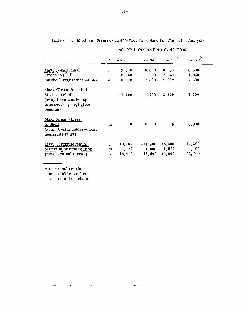
The400-foottankwassnalyzedfortheconditionofnormaloperation(plusdynamicloadfactor)followingtheapproachusedforthe200-foottank.Thefirstcomputermodelofthe400-foottankhadnoreinforcementattheshell-ringintersection.Locallongitudinalbendingstresswasnearlyequaltatheyieldstress;successivereinforce-mentgeometriesloweredthisstressto14,000psi.Thelocallongitudinalbendingstressforvariousreinforcementgeometriesispresentedintable6-III.Theappliedloadsonthe400-foottankundernormaloperatingconditions,includingthedynamicloadfactor,arepresentedintable6-I.Thelongitudinalsndcircumferentialstressdistributionsonthei~er andoutershellsurfacesat0=Ointheshell-ringintersectionregionarepresentedinfigures6-7and6-8.Again,highlocalbendingstressesinthelorfgitudinalandcircumferentialdirectionsarepresentattheshell-ring,intersection.Thevariationsinlongitudinal,circumferential,andin-planeshearstressesatselectedpointsonthecircumferenceintheshellandinthestiffeningringarepresentedintable6-Iv.
Theeffectofopm-seaenvironmentis averyimportantfactorindeterminingsafestresslevelsinthetankbecausethetank-bargesystemis subjectedtocyclicloadingduetothenatureofwavemotion.Thealternatingconditionsofsaggingandhoggingresultinwidefluctuationsindeformationateachmintinthetank.Becauseofthis

-50”Table6-III.LocalLongitudinalBendingStressatShell-StiffenerIntersection,
400-FootTank(NormalLoads)PEAK PEAKINSIDE OUTSIDE
FtEINFORCE~NT STRESS STRESS
None
Constant(1O“Lon~1.3“Thick)
Taper (10”Long;2. O“to .65” Thick)
Taper(12.5“Lon&1.95”to .65”Thick)
+27,000
+19,000
+11,000
+10,000
-34*000
-22,500
-18,500
-13,500
cyclicloading,itisnecessarytoconsiderthefatiguepropertiesoftankmaterialsand’todete~mlne,byanalysis,thestressfluctuationsduringoneloadcycleinordertodesignforthedesiredtanklife.Afatigueanalysisofthe400-foottank,basedonstressfluctuationsduetosaggingandhoggingcycles,is illustratedinsection6.4.
6.2 COMPARISONOFDESIGNTECHNIQUESTOCOMPUTERANALYSISINTHEPREDICTIONOFSTRESSLEVELSINTHETANK
6.2.1 200-FOOTTANKCONFIGURATION– The200-foottankstresslevelspre-dictedby”thesimplifiedapproach,accordingtothesimplifieddesignanalysispro-
&ce ureof Zick,aregivenintable5-I.Stresslevelswerealsoobtainedby”computeranalysisforthe200-foottank.Resultsofthecomputeranalysisarepresentedintable6-II. Thesimplifieddesign/analysistechniqueusedtodeterminestresslevelsin thetankis basedonClassicalBeamTheoryandClassicalMembraneShellTheory.Thestress variation,throughthe taukthickness,is notaccountedfor inthis approach.Onlythestress levelat themid-surfaceofthe shell is predicted.Stressdistributionthroughthetankthicknessis assumedconstant.Thecomputeranalysisis basedonClassicalThinShellBendingTheorywhichpermitsstress variationthroughtheshell
-51-
Table6-N. MaximumStressesin40&FootTankBasedonComputerAnalysis
NORMALOPERATINGCONDITION
* 9=0 0==90° e=180° 0=270°
Max..LongitudinalStressinShell-(atshell-ringintersection)
Max.CircumferentialStressinShell(awayfromshell-ringintersection;negligiblebending)
Max.ShearStressinShell(atshell-ringintersection;negligible.twist)
Max.CircumferentialStressinStiffeningRing(mostcriticalstress)
i 9,900m -3,9500 -13,800
m 11,700
m o
i 10,700m -3,7500 -18,400
6,300 6,9501,850 7,550
-4,600 8,200
7,700 3,700
8,800 0
-17,300 15,500-1,550 1,55013,500-12,500
6,3001,850
-4,600
7,700
8,800
-17,300-1,10013,500
*i =insidesurfacem=middlesurfaceo =outsidesurface
— —

-52-
15
10
5
0
-5
-10
-15
-20
‘-’e-
Figure6-7.
15
10
5
0
-5
-lo
-15
-20
Ufi
oXo
II II II I
Ofi I I
aXo Uxo
400-FootTank—NormalOperation—LongitudinalStress(0=0)
--=+=+2’’-b-=-% o II %0
iIIIII
iIIII’00 ,
400-FootTank- NormalOperation– HoopStress(O=0)
— — —
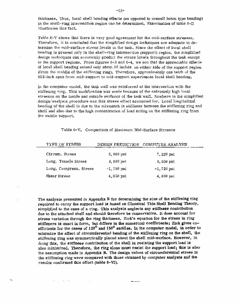
“53-thickness.Thus,localshellbendingeffects(asopposedtooverallbeamtypebending)intheshell-ringintersectionregioncanbedetermined,Examinationoftable6-11illustratesthisfact.
Table6-Vshowsthat thereis verygoodagreementfor themid-surfacestresses.Therefore,it is concludedthat thesimplifieddesigntechniquesare adequateto de-terminethemid-surfacestress levelsin thetank.Sincetheeffectoflocalshellbendingis presentonlyin theshell-ringintersection(support)region,thesimplifieddesigntechniquescanaccuratelypredictthestress levelsthroughoutthetankexceptin thesupportregions. Fromfigures6-3and6-4, wesee that theappreciableeffectsoflocalshellbendingextendonlyabout30inches oneither sideofthe supportregion(fromthemiddleof thestiffeningring). Therefore,approximatelyonetenthofthe612-inchspanfrommid-supportto mid-supportexperienceslocalshellbending.
In thecomputermodel,the tankwallwasreinforcedat theintersectionwiththestiffeningring. Thismodificationwasmadebecauseoftheextremelyhighlocalstresses ontheinsideandoutsidesurfacesofthetankwall. Nowherein thesimplifieddesign/analysisprocedurewasthis stress effectaccountedfor. Locallongitudinalbendingoftheshellis dueto themismatchin stiffnessbetweenthestiffeningringandshellandalsoduetothehighconcentrationofloadactingonthestiffeningringfromthesaddlesupport.
Table6-V. ComparisonofMaximumMid-SurfaceStresses
TYPEOFSTRESS DESIGNPREDICTIONCOMPUTERANALYSIS
Circum.Stress 6,900psi 7,220psiLong.TensileStress 5,600psi 5,550psiLong.Compress.Stress -1,750psi -1,720psiShearStress
Theanalysispresented
4,350psi 4,400pSi
inAppendixBfordeterminingthesizeofthestiffeningringrequiredh carry thesupportloadis basedonClassicalThinShellBendingTheory,simplifiedtathecaseofaring.Thisanalysisneglectsanystiffnesscontributionduetotheattachedshellandshouldthereforebeconservative.It doesaccountforstressvariationthroughtheringthickness.Zick’sequationforthestressinringstiffenersisexactinform,butdiffersinthenumerical~oefficients;UckgivesCo-efficientsforthecasesof120°aud150°saddles.h thecomputerrndel, in orderhminimizetheeffectofcircumferentialbendingofthestiffeningringontheshell, thestiffeningringwassymmetricallyplacedabouttheshellmid-surface,However?indoingthis,thestiffnesscontributionoftheshellinresistingthesupportloadisalsominimized.Therefore,theringalonemustresistthesupportload”;thisisalsotheassumptionmadeinAppendixB.Thedesignvaluesofcircumferentialstressinthestiffeningringwerecomparedwiththoseobtainedbycomputeranalysisandtheresultsconfirmedthiseffect(table6-VI).
— ———
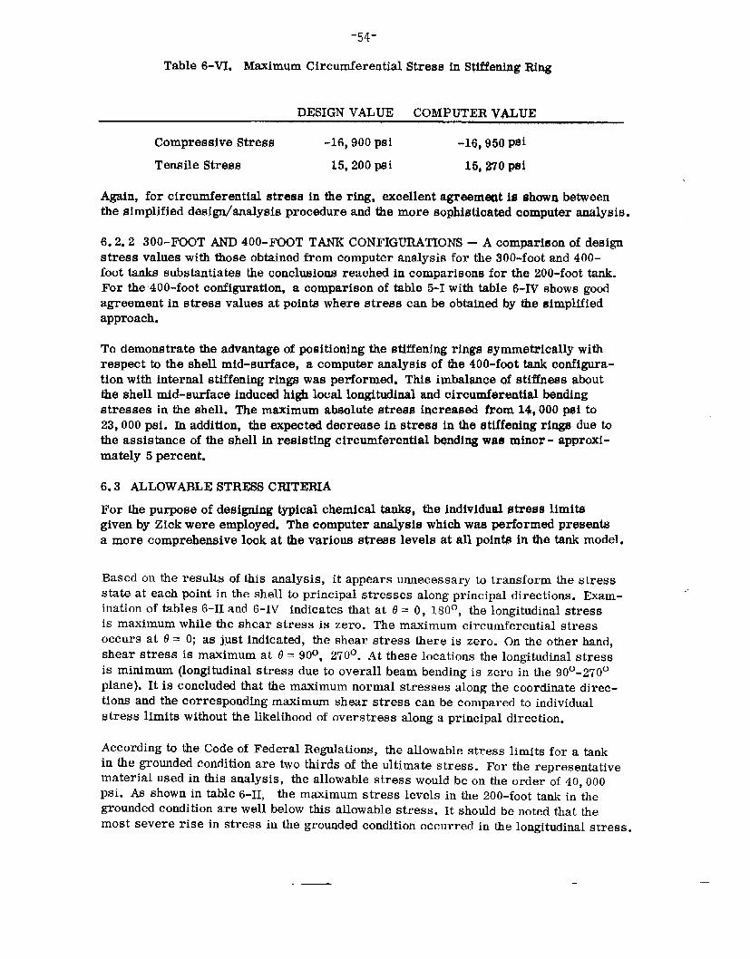
-54-
Table6-VI. MaximumCircumferentialStressinStiffeningRing
DESIGNVALUECOMPUTERVALUE
CompressiveStress -16,90013Si -16,950PsiTensileStress 15,200psi 15,270psi
Again,forcircumferentialstressinthering,exaellentagreementlashuwnbetweenthesimplifieddesign/analysispracedureandthemoresophistioatqdaomputeranalysis.
6.2.2 300-FOOTAND400-FOOTTANKCONFIGURATIONS- Acomparisonofdesignstressvalueswiththoseobtainedfromcomputeranalysisforthe300-footand400-foottankssubstantiatestheconclusionsreachedincomparisonsforthe200-foottank.Forthe400-footconfiguration,acomparisonoftable5-Iwithtable6-IVshowsgodagreementinstressvaluesatpointswherestresscanbeobtainedbythesimplifiedapproach.
Todemonstratetheadvantageofpositioningthestiffeningringssymmetricallywithrespecttotheshellmid-surface,acomputeranalysisofthe400-foottankconfigura-tionwithinternalstiffeningringswasperformed.Thisimbalsnaeofstiffnessabouttheshellmid-surfaceinductihighlocallongitudinalandcircwnfarantialbendingstressesintheshell.Themsximumabsolutestressincreasedfrom14,000psito23,000psi.Inaddition,tbeexpecteddecreaseinstressinthestiffeningringsduetotheassistanceoftheshellinrea@tingcircumferentialbqndingwasminor- approxi-mately5percent.
6.3 ALLOWABLESTRESSCRITERIAForthepurposeofdesigningtypicalchemicaltanks,theindividualstresslimitsgivenbyZickwereemployed.Thecqmputeranalysiswhichwasperformedpresentsamorecomprehensivelookatthevariousstresslevelsatallpointsinthetankmodel.
Basedontheresults ofthis analysis, it appearsunnecessarytotransformthestressstate at eachpointin theshell toprincipalstresses alongprincipaldirections.Exam-inationof tables6-11and6-IVindicatesthatat0= O,180°,thelongitudinalstressis maximumwhiletheshearstress is zero. Themaximumcircumferentialstressoccursat 0= O;as just indicated,theshear stress thereis zero. Ontheotherhand,shear stress is maximumat 13=90°, 270°.Attheselocationsthelongitudinalstressis minimum(longitudinalstressduetooverallbeambendingiszerointhe90°-270°plane). Itis concludedthatthemaximumnormalstressesalongthecoordinatedirec-tionsandthecorrespondingmaximumshearstresscanbecomparedtoindividualstresslimitswithoutthelikelihoodofoverstressalongaprincipaldirection.
AccordingtotheCodeofFederalRegulations,theallowablestresslimitsforatankinthegroundedconditionaretwothirdsoftheultimatestress.Fortherepresentativematerialusedinthisanalysis,theallowablestresswouldbeontheorderof40,000psi.Asshownintable6-II, themaximumstresslevelsinthe200-foottankinthegroundedconditionarewellbelowthisallowablestress.Itshouldbenotedthatthemostsevereriseinstressinthegroundedconditionoccurredinthelongitudinalstress.
.— —

-55-
Thisis theresultofanincreasedoverallbendingmomentactingonthemostseverelyloadedsupport.
Inthegroundingcondition,themaximumlongitudinalcompressivestressis increasedfrom-1,720psito-10,500psi.Zick’slongitudinalcompressivestresscriterionisbasedonbuckling,andvaluedat-4,700psi.Thephenomenonofbucklingprecludesthatoffailurebyyielding,andthereforeitwouldseemthatthetankinthegroundedconditionwouldbeindangerofbuckling.However,asdescribedearlier,theultimatestresswhichwillproducebucklingofsuchacylindricalshellhasbeendeterminedtobe-10,700psi,basedonananalysisbyTimoshenkowhichaccountsforinitialshellimperfections.Thisdiscrepancycertainlydeservesadditionalinvestigation.
Noattempthasbeenmadetojudgethemagnitudesofthestresslimitswhicharebasedontheallowableworkingstressofthetankmaterial.
6.4 DISCUSSIONOFFLUCTUATINGSTRESSESDUEToSAGGING/HOGGINGINLARGETANKS
Asdiscussedpreviously,theuseof400-foottanksforthetransportationofchemicalsincoastalwatersoropenseaintroducestheadditionaleffectofcyclicloadingduetowavemotion.Amaximumofabout7.2millioncyclesofhoggingandsaggingmaybeexpectedduringaten-yearlifeperiod.Ofthe7.2millionwaveencountersonlyaverysmallnumberofwaveswhichinducemaximumbendingwilloccur.Duringcyclesofhoggingandsagging,thelongitudinalstress dueto bendingfluctuatesaboutthestressconditionofnormaloperation.
Toillustratethemagnitudeofstressfluctuationsundersevereconditionsina400-foottank,theloadconditionsforthecasesofhoggingandsagging(determinedinsection5)wereutilized.Notingthatthemaximumvariationinbendingmomentsoccursatthemiddleofthetank,acomputeranalysiswasperformedforbothhoggingandsaggingforthesectionoftankhalfwaybetweensupportsoneithersideofthecentersupport.Theanalysisisanalogoustothatperformedforthenormaloperatingconditionofload.Havingdeterminedthestressdistributionforbothextremecases,thestressintensity(range)andmsximumstressatcertaincriticallocationswerecalculatedandarepresentedinfigure6-9andtable6-vII.Thestresslevelsshownrepresentextremeconditionsandwilloccurorbeexceededonlyasmallpercentageofthetime.

-,
-56-
TopofTank ~ +11,350psi
BottomofTank -7,650psi
TopofTank
Condition
BottomofTank ~-3,850psi
c)Sagging
‘~”BottomofTank ~+15,850psi
LongitudinalMembraneStressCycleintheShellattheIntersectionwiththeWiffeningRing (dynamicloadfactorusedinallcases)
Figure6-9. Inv@at@itIonofCyclicLoadingforFatigueAnalysisof400-FootTank
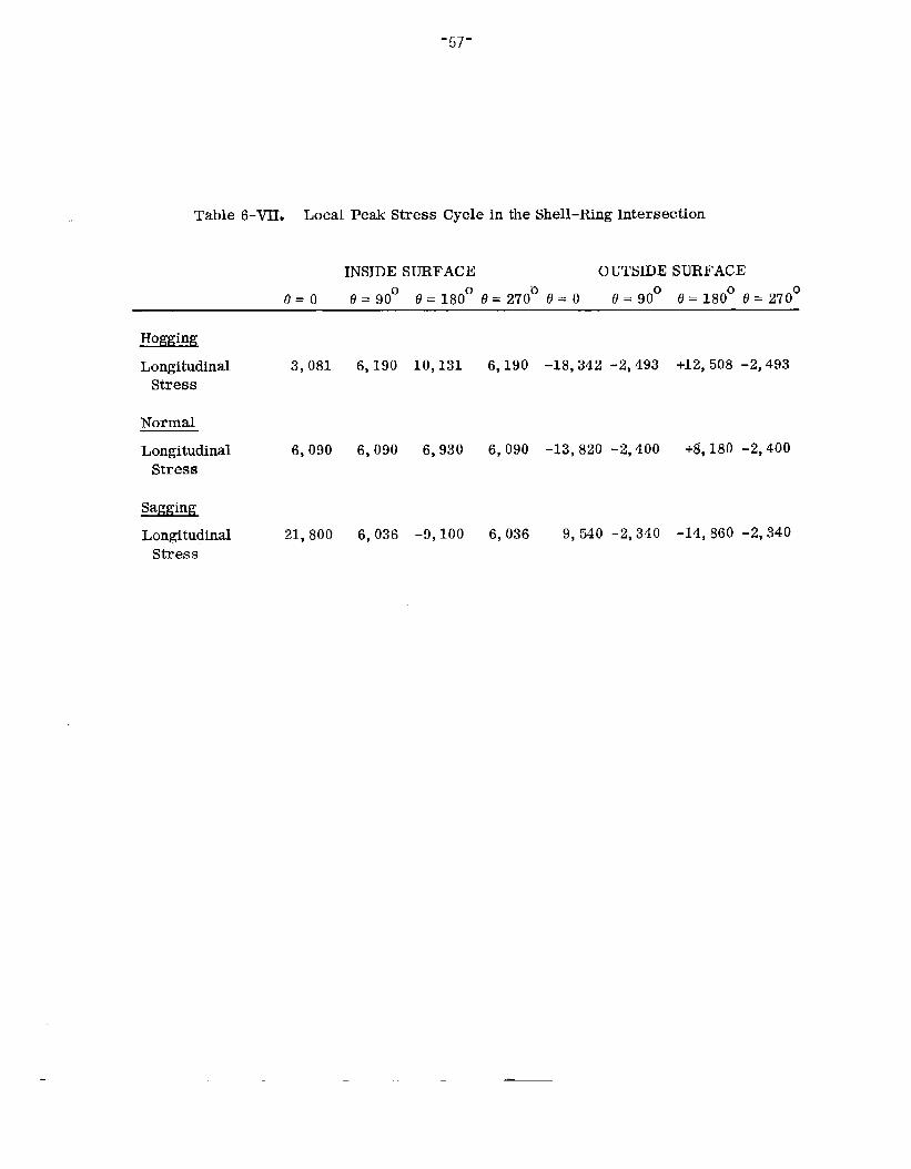
-57-
Table6-VII. LocalPeakStressCycleintheShell-RingIntersection
INSIDESURFACE OUTSIDESURFACE0=0 e=90° 8=18000=27000=0 0=90° @=180°0=270°
E%i2!uiLongitudinal 3,081Stress
NormalLongitudinal 6,090Stress
&@!&Longitudinal 21,800Stress”
6,190 10,131
6,090 6,930
6,036 -9,100
6,190 -18,342-2,493 +12,508-2,493
6,090 -13,820-2,400 +&180-2,400
6,036 9,540-2,340 -14,860-2,340
— —

’58-Section7
DISCUSSIONOFMATERIALSANDCONSTRUCTIONOFPRESSUREVESSELSFORBULKTRANSPORTOFLIQUIDCARGOESONBARGES
Thetransportofliquidcargoesintankbargesis regulatedbyfederallawforinter-stateandoverseasshipment.Thedesign,constructionandinspectionoftanksisgovernedbyTitle46oftheCodeofFederalRegulations.
CertaincargoespossessingdangerousorlethalpropertiesarelimitedbytheCodeastothemaximumvolumeorweightwhichcanbecarriedinasingletank.Thisisbecauseatankofsuchavolumeorweightis themsximumthatcouldreasonablyberecoveredwithoutexcessivedangertopersonsandpropertyshouldthetankbargesuffera casualty.Suchcargoes,andtheirtanks,areofconcerninthisstudyonlytotheextentthatsafehandlingorequipmentforrecoveryfollowingabargecasualtymightbeimprovedinthefuture.
Thisdiscussionis, therefore,directedprimarilytowardsrequirementsfor tankswhichcontainotherthanlethalliquidsandwherenoregulationsrelativeto thefluidpropertiesgovernthesize ofthetank. It is, furthermore,primarilyconcernedwithliquidsat subatmospherictemperaturesandatmosphericpressurewherepressurevesseldesignmustbeemployedandtemperatureeffectsonmaterialsmustbeconsidered.
Thissectionisnotanabstractofr~uirementspertainingtopressurevesselsperse, butanappraisalofthoserequirementswhichcouldaffecttheconstructionofverylargecargotanksofpressurevesseldesign.
7.1 DESIGNIMATERIALCONSIDERATIONSLargecylindricalpressurevesselsforcargoesbeingtransportedatsomewhataboveatmosphericpressure,theoretically,canhaveverythinwalls.However,atzeropositivepressure,thestaticpressureheadofthecargoonthelowerportionofahorizontalunstitfenedtankcanbesufficienttoeffectconsiderabledeformation.Forinstance,thepressureexertedbytheweightofpropanegasonthebottomofahorizontaltank40feetindiameterwillbeontheorderof145lbspersquarefoot.Thecylinderalsocandeformfromitsownweightifunsupported.Therefore,todesignatankwhichwillremainessentiallycylindricalandbeofminimumweight,abalancemustbeestablishedbetweenthenumberandsizeofstiffe~ers(internalorexternalframes), shellthickness,andmaterial.Thisis, inessence,thepurposeofthisstudy.Forlargetanks,thesectionmodulus,includingdepthandsizeofstiffenersandshellthickness,determinestherigidityofthestructureandthemaximumstressesatthesupportingsaddles.Designseekstokeepstresseslow,hence,materialstrengthpropertiesaresecondarytosectionsize.Forthisreason,high-strengthquenchedandtemperedsteelsmaynotbeeconomicallyjustifiable.However,sincetheyhaveexcellentnotchtoughnessWdretaintheirpropertiesofductilityandtou@-nessacrossweldedjointswithoutstressrelief,thehighermaterialcostmaybeoff-setbyfabdicationeconomies.
Minimumshellthicknessof 5/16inchis specifiedintheCodeofFederalRegulationsforcertainhazardousanddangerouscargoes(inparagraphs38,39and40ofSub-

.59-
chapterD).Forverylargetanks,designindicatesagreaterthicknessisnecessaryforreasonablestresslevels,thusthislimitationis ofnoconsequence.Sincethehigheststresses onthetankare foundat thesaddlesupportsbywhichthetankisattachedto the barge, localthickeningof theshellin theseareas willreducereactionstresses withminimumoverallincreasein tankweight.
Exceptwherecorrosion-resistantmaterialsare usedwhichare notaffectedbythecontainedfluids,or thecargois noncorrosive,mosttanksrequireacorrosionallowanceaddedb thedesignshell thickness.Paragraph52.05-12ofSubchapterFspecifiestheadditionof1/6 thedesignthickness,or 1/16inchwhicheveris less.Thisadditionis generallyofsmallconsequencewithrespecth theoargucapacityof the tank.
7.2 MATERIALSFORLOW-TEMPERATUREAPPLICATIONSTheCodeofFederalRegulations,Title46,Chapter1, Su~hapterF, “MarineEngineering,” 1968edition,designatesallowableferriticmaterialsfor low-tempera-ture servicein Table51.24.1. ThetablereferstoASTMspecificationsA300-5E,A333-63T?A334-63T,A350-61TandA352-60T.Whilethese s~cificationsare.all currentat this date (1968),eachhasbeenupdated,and incaseofA300,revisedto a considerableextent.Therefore,whendesigninga pressuretank, it mustbedeterminedwhetherthe CFRis to befollowedto the letter or thelatest revisionoftheapplicablespecificationis to beused.
TheU.S. CoastGuardNavigationandVesselInspectionCircular,No.7-67,dated9November1967,isacomplete(current)guidefor theuseofall steels (ferritic andaustenitic) in all forms– plate, shapes,castings,fastenings,andm forth– forlow-temperatureservicefromambientto below-320°F.Itappearsespeciallyvaluablein that, toa great extent,it doesnottie materialsto specifications,butnoteschem-istries andheat treatmentsrequiredtoprovidethestrengthandtoughnessfor theservicetemperature.Thus, thedesigneris free h choosethematerialbestsuitedto his applicationwithonlyprudentandreasonablerestrictionsinvoked.Nonferrousmaterialsare notincludedi4 circular 7-67, butmaybeusedat anylowtemperatureuponapprovsloftheapplicationbytheCoastGuardCommandant.Thisis specificallynotedinCircular7-67andinParagraph51.01-85,‘~Alternative~abrials” ofSub-chapterF, Title46-Chapter1 oftheCodeofFederalRegulations.
Withrespecttotoughnesspropertiesofferriticsteelsforlow-temperatureapplica-tions,ther~uirementthatfinegrainmeltingpracticebeemployedinmakingthesteelisuniversallyprescribedinspecifications.Also,Circular7-67emphaticallystatesthatwhereCharpyimpacttestingisusedtoevaluatenotchtoughness,theV-notchspecimenonlyisacceptable.Itis statedthereinthatcorrelationhasbeenes-tablishedbetweenthenil-ductilitydrop-weighttestandtheCharpyV-notchtestandthateitherofthesetwomethodsmaybeused.
CertainoftheASTMspecifications, includingA300-63T,specifytheCharpykeyholeimpacttest.WhereanASTMspecificationisusedtadesignateferriticsteelsfo,rbargeor shiptanks,andCharpyVorkeyholeimpactspecimensarecalledforbythespecification,thedesignermustindicatethattherequirementsofCircular7-67forCharpyV-notchteststakeprecedence.

Thosematerialswhichdonotundergoa ductile-to-brittletransitionwithdecreasingtemperature,suchas aluminumandausteniticstainlesssteel, are, in general,exemptfromimpacttesting. The.curveofimpactenergyversustemperatureisanearlyhor-izontallineto-3200F, thereforeimpacttests providenousefuldata.
Circular7-67, Paragraph4C, notesthatevaluationofmetaltoughnessis a fieldundergoingcontinueddevelopment.Thisis a referenceto thepresentemphasisonfracturemechanicswhichseeksto establishquantitativemeasurementsofmetalre-sistanceto brittlefailureandmathematicalanalysesofthisphenomena.Newtestiugtechniquesare beingevolvedwhichpromiseto bemoresignificantthanthepresentimpacttests, andthesewillberecognizedbytheCoastGuardas wellas otherCodebodiesastheyarerefinedandstandardized.
Thechemicalcharacteristicsofcertaincargoestransportablein steel tanksprohibittheuse ofsomeof the low-alloy,hightensilesteels. Ethleneoxideandpropyleneoxide,for instance,canbesafelycarriedin carbonsteel or austeniticstainlesssteeltanks, butcannotbe carriedin tanksofcopper-bearinglowalloysteel, suchasLukens’LT-75or U. S. Steel’sT-1, bothexcellent,low-temperaturesteels, becauseofreactivitywiththecopper.Thisparticularprohibitionis notedin Section40ofSubchapterD, Title46oftheCodeof FederalRegulations,andillustratesthat thenatureofthecargomustbecarefullyconsideredwhenselectingtankmaterial, inadditionto requirementsfor low-temperaturemechanicalproperties.
Table7-Iisacompilationofferriticsteels,stainlesssteelsandaluminumalloyplatespecificationsfromtheAmericanSocietyforTestingandMaterials,togetherwithpertinentmechanical/physicalproperties,whichcanbeusedforsub-ambienttemperaturecargotanks.Thesematerialscoverthetemperaturerangefromambienth below-400°F.
7.3 FORMINGREQUIREMENTSThemethodofformingparts for pressurevessels, in general,is notrestrictedbyCoastGuardor AM regulations.However,in order to takeadvantageofallowedmechanicalstress reliefprof;duresfor completedtanks,parts canbecoldformedtnonly4 percentplasticstrain . If individualparts, suchasheads,arestrainedmorethan4percentthroughcoldworkwhen.beingfabricated,theymustbethermallystressrelievedbeforeassemblyintothetankinorderthatthetankmaybemechanicallystressrelieved.Itisnotclearif thislimitonplasticstrainappliestocoldformingofnonferrousmetals;butwherea metalis knownto strainharden,it maybeassumedthat thermalstress reliefofseverelycoldworkedparts is required.
Tolerancesare appliedto theformedsectionsas directedbyParagraphs56,01-50and56.01-75ofSubchapterF ofChapter1, Title46CFR. Outofroundnessislimitedto 1percentof themeandiameter.Ina 40-footdiametertank, thisamountsto~4.8 inchesfromthetruediameter,Generallyspeaking,this is a generoustoleranceat this diameter.Submarinehullsof this orderofmagnitudeindiameterare heldtoout-of-roundnesstolerancesofless than1 inch.
Mismatchofabuttingedgesshallnotexceed1/4oftheplatethickness,or1/8inchforlongitudinaljointsand1/4inchf~rcircumferentialjoints,whicheveris less.Thistolerancerequirescareinthefabricationofthecylinders,since,intherollingofplates,itispossibletaformcylinderswhichvarybymorethan1/2inchindi-

Table7-1 MaterialProperties
MODU-WORK- LUSING OF COEFF. THERMAL SPEC.
HEAT STRESSELAS- OF CONDUC- HEAT@TREAT-20TO TICITY THERMALTI TY% TENSILE YIELD 70*F DENSITY
DESIG- CONDI- 650 x 10° CHARPY~PANSI~N(FT~HR) STRENGTHSTRENGTHBTU L3SNATION ALLOY TION (Pm) (PM) v-NoTcH(IN./IN./ F) (FT’F) (PSI) (PSI) (LB/°F) (CuIN.)
03B 21/2-31/2%Normal-17,500A203B NiSteel izedA203E 21/2-3l/2~ Normal-17,500
NickelSteel
A353 9%NickelSteeI
A410 Chrome-Copper-Nickel-AluminumAlloy
A516Gr55Carbon-Manga-neseSiIiconSteel
A516Gr60Carbon-Manga-neseSiliemSteel
A51~Gr65Carbon-Manga-neseSilicwlSteel
ized
Double 23,750Normal-ized&temperedNormal-15,000ized
Normal-13,750ized
Normal-15,000ized
Normal-16,230ized
29-30
29-30
29-30
29-30
30
30
:0
15ftlba@-75°F15fflbs@-150°F
25ftIbs@-32WF
15ft lbs@-l!30°F
15ft lbs@-5WF
151tlbs@-50°F
15ftlbs([h-50°F
.0000064 24.2
.0000064 24.2
.00000527 15.2[-58to32-F)
. oooooG’1
.0000064
,0000064
.ouooo(i-I
70,ooo-85,00070,ooo-85,000
100,ooo-120,000
60,000
55,ooo-G5,000
60,000-72,000
(i5,000-77.000
40,000
40,000
75,000
30,000
30,000
‘J.J,Oofj
35,[)00
0.11-0.12,283
0.11-0.12.283
0.11 .283
u,11 ,283
0.11 .283
0.11 .283
(),11 .283
AI

Table7-1(Cont.)MODU-
WORK- LUSING OF COEFF THERMAL SPEC.
HEAT STRESSELAS- OF CONDUC- HEAT[!TREAT-20TO TICITY THERMALTIVITY TENSILE YIELD 70°F DENSI
DESIG- CONDI- 650 x 100 CHA1{PYEXPANSION(FT2JHR) STRENGTHSTRENGTHBTU LBSNATION ALLOY TION (PSI) (PSI) V-NOTCH(IN,:IN./°F) (FT/°F) (Ps[) (PSI) (LBJ°F) (CVIN.)
A516Gr70Carbon-Manga-neseSiliconSteel
A517,all Chrome,grades Nickel
andmolyb-denumlowalloys
A537GrA Carbon-Manga-nese-SiliconSteel
A537GrB Carbon-Manga-neae-SiliconSteel
A538GrA 18NickelMarag-ing
SteelA538GrB 18
NickelMarag-ing
Steel
Normal-17,500 30izecl
Q&T 28,750 30(150°F&lower)
Normal-1’7,500ized
Q&T 20,000
Precip- 52,500itationhard-ened
Precip- 60,000itationhard-ened
30
30
26.5-27.5
26.5-27.5
15ft lbs .0000064@-50°F
30
15ft lbs ,00W.)064 30@-50°F
15it lbs ,0000064@-75°F
Byagree- ,00000597mentbe-tweenmillandpur-chaserByagree- ,00000597mentbe-tweenmillandpur-chaser
30
30
11.3
11.3
70,000 38,000 O.lL ,283
115,ooo- 100,000 0.11 0.283135,000 ~,289
70,ooo-90,000
80,000-100,000
210,000
240,000
50,000 0.11 .284
60,000 0.11 .284
200,000- — 0.29235,000
230,~00- — O.29260,000

-63-
mmml
-Fwml
mmaa“
I1
Zz-Om- m“r-oNM
.
m,+ .-.
4.
,-! .
xo00m“m
o0a0“a
Am0003o000’mN
c-E00000
.
z0is,4,4
ww“ 1.5
N
l-lI
c-
. .
o 3 0Lcl 0 mt- Ln t-m“ .m“c-l m :
0000-r-
0mC-J

Table7’-1(Cont.)
MODU-WORK- LIEING OF COEFF. THERMAL SPEC.
HEAT STRESSELAS- OF CONDUC- HEAT@TREAT-20TO TICITY THERMALTIVTY1 TENSILEYIELD 7(.)°F DENSITY
DESIG CONDI- 650 x 10° CHARPYEXPANSION(FT/HR) STRENGTHSTRENGTHBTU LBSNATION ALLOY TION (PSI) (PtH) V-NOTCH(IN./lN./°F) (FT/°F) (PSI) (PSI) (LB/gF) (CUIN.)
A240 18-8Type302 Cr-Ni
304 Stain-316 lese321 Steel347
A240 18-8Type304LLOW
316LCarbonStain-lessSteel
A240 ChromeType410 Stain-
430 leseB2095052Alumi-
numAlloy
B2095083Alumi-numAlloy
B2095086Alumi-numAlloy
B2095456Alumi-numAlloy
B2096061T6Temper,Welded
An-nsaled
An-nwhd
An-nealed
o-Temper
o-Temper
o-Temper
o-Temper
o-Temper
18,750
17,500
16,250
6,250
10,000
8,700
10,500
6,000
28-30
28-30
29
10.1
10.3
10.3
10;3
10.0
Ductileto .0000092cryogenictempe.
Ductileto .0000092cryogenictemps.
Ductileto .0000055cryogenictemps.Ductileto ,000012cryogenictempe.Ductileto .000012cryogenictempe.Ductileto .000012cryogenictempe.Ductileto .000012cryogenictemps.IWctileto .000012cryogenictemps.
9.5
9.5
14
80
68
73
68
99
75,000
70,000
65,000
25,000
40,000
35,000
42,000
24,000(Welded)
30,000
25,000
30,000
9,500
18,000
14,000
19,000
0.12
0,12
0.11
—
—
—
—
, 287-,292
,287-,292
.28
.097
.096
.096
.096
.098

-65-ameter.Forinstance,a40-footdiametercylindermayactuallybemorethan1/2inchtoosmallor toolarge.Carefulmeasurementofeach.y,olledplateandweldjointsetup,withallowancesfororrestraintofcontraction,willcircumventproblemsinthisrespect.
7.4 WELDINGCONSIDERATIONSWeldingproceduresforallmaterialsusedintankswhichwilloperateatlowtem-peraturesmustincludeconsiderationofnotchtoughness.Inadditionb thetensileandbendtestspecimensusedtoqualifyaweldingprocedure,specimensarerequiredfortoughnesstestingbyeithertheCharpyV-notchimpacttestorthenil-ductilitydropweighttest.Similarly,productionweldtestingperformedinaccordancewithSection56ofTitle46,Chapter1, CodeofFederalRegulations,mustincludeoneofthesetoughnesstests.
Weldingfillermetalis restrictedtothosecompositionscapableofpassingimpactordrop-weighttests.ASTMspecificaticmA233(MildSteelCoveredArcWeldingElec-trodes) showsthattheExx12,13,14,20and24classificationelectrodescannotbeusedsincenotoughnessrequirementis imposedonmetaldepositedbytheseelec-trodes.Similarly,forlow-alloysteel,flux-covered,arcweldingel-trodes,onlytheExx15,16and18classifications(lowhydrogenandlowhydrogenironpowdercoatings),exceptallE70= classes,[email protected],onlythesewouldbeacceptable.
Barewireforsubmergedarcweldingandinertgasshieldedwelding(ASTMA558andASTM599,respectively)isalsoclassifiedtoincludeorexcludenotchtoughnesstests.Onlythosegradessubjecttoimpactrequirementscompatiblewiththeplatesteelfor&edesignservicetemperaturecanbeusedfOrbV-tempeHttUr13bh.
Forradiographicqualitywelding,as is required for Class I andClass 11tanks,a certain amountofweldingelectrode control is required, especiallywithregardto moisture contentin the coveringof flux-coatedelectrodes and surface cleanlinessof spooledautomaticweldingwire. This is especially true for the higher tensilestrength electrodes, whereabsorptionof atmospherichumiditycan lead to entrap-mentof hydrogenin theweldswithsubsequentunderbeadcrackingandhydrogenflakes, or “fish eyes. “ Preventionofhydrogenentrapmentrequires bakingof theelectrodes andholdingthemin a heatedovenuntil theyare to be used. In some cases,especially in shipyards, electrodesmayremain out’of the ovenin the welder’sposses-sion for a limited time ordy– four to six hours —before beingrebakedto drive outabsorbedmoisture.
Foraluminumtanks, it mustberememberedthatthestrengthoftheweldgovernsthestrengthof thestructure. Themagnesium-alloyed,corrosionresistant, 5000series aluminumshavethebestweldstrength-to-platestrengthratio. Thealloy6061,andotherheat-treatablealuminums,whilecapableofhighstrength,are in-effectivesincetheweldsoflargetankscannotbesuitablyheattreated.Intheas-
ld d diti ld i 6061 ll l ti l kTh Ch V t ht t

-66-
7.5 STRESS-RELIEVINGCONSIDERATIONSParagraph56.01-70in Subchapte~F onMarineEngineeringin theCodeofFederalRegulationsstates thatall ClassI pressurevessels (unlessspecificallyexemptedbyothersectionsofthesubchapter)shallbestress relieved.Thefollowingparagraphsindicatethatonlythermalstress relievingis allowed.Thiswouldappeartoeffectivelylimit thesize oftanksfor ClassI servicesincethermalstress relievingofverylargetankscanbeextremelyexpensive.It’a furnacewhichwouldaccommodatethediameterof thetankdoesnotexist, onemustbebuiltandits costaddedto thetankcost.Furthermore,sincelargetanksare assembledonthebargehullbecausetheyaretoounwieldytohandlewhenassembled,circumferentialweldsjoiningstress-relievedcylindricalsectionsmustbelocallystress relieved.Thiscanpresentformidableproblemsofuniformheatapplicationandcontainmentto attainstress-relievingtemperatures.
ClassIIvessels,whichare theprimaryconcernofthis study,mustalsobestressrelievedin manyinstances.Exceptionsto thestress-relievingrequirementsexisthowever,whichmakeconstructionofjumbotankspractical.Stressrelievingis re-quiredofmildsteel(carbon-manganese-silicontype)onlyif theshellthicknessex-ceeds1.25inches(assuminglargetanksover20feetindiameter).AHOYsteelunderO.58inchinthicknessis exemptfromstressrelief.Mechanicalstressrelief,ef-fectedbyhydrostaticpressurization,ispermittedbyMerchantMarineTechnicalNote7-64of3December1964forClassIiandClassIIIvessels.Sincemechanicalstressreliefis theonlypracticalmethodtoemployonverylargetanks,thelimitsprescribedforitsusebyTechnicalNote7-64shouldbeconsidered.
Thefirstlimitationnotedis thattheyieldstrengthofthematerialmustbelessthan80percentofthetensilestrength.ThislimitationmightapplytomanyquenchedandtemperedsteelssuchasASTMA517,A542andA543.
Aspointedoutearlier underDesignConsiderations,theuseofhigh-strengthsteelmaynotbeattractivewheresectionmodulus,tominimizedeflectionandstress, isrequiredrather thantensilestrengthtopermithighstress. If, ontheotherhand,unwantedweightcanbeeliminatedbyhigherallowablestress, theuseofquenchedandtemperedsteels mightbeverydesirable.Insucha situation,andin thecaseofa verylarge tank, theprohibitionagainstmechanicalstres6 reliefof thesematerialsandthepresentrequirementto thermallystress ralievealloysteeloverO.58inchmightbecircumventedonthebasisofexperienceandtestingwhichindicatesthesesteelswillperformsatisfactorilywithoutanystress relief.
In1966,MPRAssociatespublishedareportentitled“TechnicalJustificationforUseofNi-Cr-MoQuenchedandTemperedSteelinClassBNuclearVessels.” Thisre-portwasaimedat theuseofQandT steel for nuclearreactorcontainmentvesselswhich,becauseoftheir size, shouldbemadeas lightas possible.Thefunctionofthecontainmentvesselis toprovidemaximumsafetyin theeventofmalfunctionofa nuclearreactorbycontaininga suddenrise inpressure. Thesevesselscannotbe

-67-
benefitedbythermalstressrelief.Toughnessis loweredandatendeneytowardheat-affectedzonecrackingdevelops.Thefactthatmanylargestructuressuchassub-marines,bridges,penstocksandstoragetankshavebeenconstructedis evidencethatthestressreliefrequirementcanbewaived.
Stressreliefis, inlargemeasure,desirabletoenhancefatigueresistancewhichmaybeanimportantfactorinatankonanocean-goingbargesubjecttowaveaction.Inthisrespect,itmaybenotedthatinthepresenceofflaws,high-strengthsteelsof80,000to100,000psiyieldstrengthhaveanendurancelimitofabout25,000psi,aboutthesameascarbonsteels.However,acarbonsteelstructuredesignedtoaworkingstressof15,000psiwillbeoverdesignedwithrespecttoitsendurancelimit.Aquenchedandtemperedsteeldesignedto.25,000psiworkingstresswillstillhaveaninfinitefatiguelife,assumingadequateweldingcontrolandnondestructivetestingisperformedtoassurefreedomfromgrossflaws.Quenched‘andtemperedsteelsof100,000tO 125,000tensile strengtharenotpronetostresscorrosionproblemsortobrittlefracture.Hence,ifdesigned,constructedandtestedtomini-mizefatigueresistance,theycouldbeexpectedtoperformsatisfactorilywithoutstressrelief.Itmaybenotedthatthenormalized9percentnickelASTMA353steelhasbeenapprovedunderASMECodeCase1308forfabricationtol-1/4-inchthicknesswithoutstressrelief.
Thesecondlimitationofmechanicalstressreliefis thatthedesigntemperatureshallnotexceed115°F. Thisstudyisconcernedwithlow-temperaturecargoes;therefore,theimplicationsofthisrestrictionarenotgermainetothepresentcase.Similarly,thisstudyis concernedwith“cargoestransportedatpressureslessthan100psi,andmechanicalstressreliefis generallynotrequired.
Afurtherrestrictiononmechanicalstressrelievingisthatthecargoescarriedshallhaveaspecificgravityof1.05orless.VeryfewcargoestransportableinClassIItankswouldfallinthiscategory,thustheeffectofthisrestrictionisnotconsideredsignificant.
Certaindetailsofconstruction,especiallyinreinforcedopenings,cannotbesatis-factorilystressrelievedbymechanicalmeansbecauseofinherentnotches(partialpenetrationnozzleweldsandsinglebevelweldswithnon-removedbackingstrips).DesignmusttakenotetoavoidsuchdetailswhicharespecificallynotedinMemorandum7-64.
Vesselsmustbedesignedtoeliminatestressconcentrationswhichmightleadtoex-cessiveplasticdeformationor, possibly,tofailureunderstress-relievinghydraulicpressure.
Lastly,unlessanextensivestressdeterminationisperformedwithstrainindicatorsduringthestress-relievingoperation,operatingpressureis limitedto40percentofthemaximumdesignpressure.Generallyspeaking,sincetheoperatingpressurei l t th t h i f th i t d d ft k id di thi

-68-thermalstressreliefdoes. Therefore,theuseofmaterialssusceptibletostresscorrosioncrackinginthepresenceofcertainfluidsmustbecarefullyanalyzedbeforewaivingthermalstressreliefinfavorofmechanicalstressrelief.
7.6 NONDESTRUCTIVETESTINGCONSIDERATIONSConstructioncostscanbeaffectedbytheamountofnondestructivet~stingspecifiedfora ClassIItank.Creditisgiveninweldefficiencyforradiographicinspectionupto100percentforflushground,radiographed,andthermallystress-relievedweldsinClassIvessels.Spotradiographyofoneareaper50feetofweld,usedinClassIIvessels,reducesdesignjointefficiencyto90percentwhereweldreinforce-mentis removed,andlowerstheallowableworkingstrengthoftheplate,requiringadditionalplatethickness.Itthereforebecomesnecessarytocomparethecostofadditionalplateweight(includingeffectofsuchadditionalweightoncargocapacity)andadditionalweldingwiththecostofcompleteradiography.Vesselweightisusuallyaverysmallpercentageofcargoweight,andradiographyis relatively=pensive.
Anadditionalefficiencyofonly5percentcanberealizedforfullradiographiccoverageforClassHvessels,and,therefore,wherespotradiographyisacceptable,itisgenerallypreferredto100percentcoverage.Inordertotakeadvantageofprovisionsformechanicalstressrelievingoftanksoperatingat-20°Forlower,spotradiographymustbe-tendedtoincludejunctionsbetweenlongitudinalandcircumferentialweldsandfor20timestheplatethicknessineachdirectionofweldfromthejunction.Itshouldalsobenotedthatcreditinweldefficiencyisnotgivenformechanicalstressrelievingasitis forthermalstressrelieving.
7.7 CARGOCHARACTERISTICS
Toassess thedesignproblemsassociatedwithlargetankbarges,itisnecessarytoknowthephysicalcharacteristicsofthosematerialswhicharecurrentlybeingcarriedintanksormightbeusedinsufficientquantitiest~warrantsuchtransporta-tion.
Table7-II,entitled“PhysicalPropertiesofGasses,‘‘ isacompilationofsomeofthemoresignificantphysicalcharacteristicsofthosegasseswhicharenowtransportedintheliquidstateorwhichmightreasonablybesocarriedinthefuture.TheCoastGuardtoxicratingandclassificationarealsoincludedinthetableforthosegasseswhichhavebeenso ratedandclassified.ThisdatawascompiledfrombothCoastGuardandcommercialpublications(references4, 7, and2.2through27).
TheImilingpointofthecargomustbeconsideredintankdesignsinceitwillinfluencethechoiceoftankmaterial,degreeofstressrelief,andweldingpractice.Thespecificgravityofthecargointheliquidstatewill,inpart,determinethestructuralloadingonthe barge. Theflammabilityofthecargois a measureofthehazarddueto leakagefromthetank.
TheCoastGuardtoxic isanindexofthehazardta fromcontact

Table7-IL PhysicalPropertiesofGases
Et-m3
-ma
.4L
-CDa I I I I I i I I I I 1 Im]C,* Mcnoli*CbmkalItitq -s12,# 0,810 12,5 74 B@nim
. . P019mO,mas .lll.:/3m pm
DGzmT8=Mw c.0. Chdnuiia
AUI1

Table7-II.(Cent’d)
I
vAmn
VAmm ET* CEt’1’lCALTEMP.fmr A m
TAMXMATUIAL m. %&’uRr (P,L%%% 1.talj PR-C
41]Ammbh~ IClOmleil*.~.i 170 ‘“ 10.743 no H.o I s
.,

-71-Thecriticaltemperatureandpressureisausefulindexofstability.Ifthecargoachievesthisstateandthetemperatureisexceeded,therewillbeachangeofstatefromliquidtogasregardlessofpressureincreases.Thisdata,combinedwithliquidandvaporphasedensities,definesthesafetyblow-offrequirementswhichwouldbeneededtoprecludetankrupture,shouldcriticalconditionsbeexceeded.
Table7-IIshowsthatthereareavaryingnumberofphysicalcharacteristicsassociatedwithmaterialswhichareorcouldreasonablybecarriedinrefrigeratedtanks.Ac-cordingly,a basicdecisionmustbemadeinitiallytodesignallsuchrefrigeratedtanksforthemostsevereservice,designtanksforoneor twosimilarcargoes,ordefinerangesofcharacteristicsanddesignforthemostsevereservicewithinthatrange.

-72-
ACKNOWLEDGEMENTS
Theauthorwishestothankthefollowingfortheircontributionstotheperformanceofthisstudyandtothepreparationofthispaper.
Mr. A.T.
Mr. R.C.
Mr. G.F.
Mr. R.J.
Mr. R.S.
Mr. R.A.
Fahlman,NavalArchitect,ElectricBoatGwin,Hydrodynamicist,ElectricBoatLeon,StructuralfiesearchEngineer,ElectricBoatMorante,StructuralResearchEngineer,ElectricBoatSnow,MaterialsEngineer,ElectricBoatToher,EngineeringSupervisor,ElectricBoat
Mr.DelBreit,BreitEngineeringCo.CDR.R.L. Brown,U.S.CoastGuardMr.
Mr.
Mr.
GeorgeDrake,NavalArchitectJohnEstes,Bethlehem/BeamountShipbuildingDiv.JohnFoley,AmericanBureauofShipping
LCDR.DeanFrankenhauser,U.S.CoastGuardCDR.R.C. Hill,U.S.CoastGuardMr.WilliamE. Hill,PortHoustonShipyardMr.SbnhopeHopkins,CanalBargeLinesCDR.J.L. Howard,U.S.CoastGuardMr.R. Johnson,GulfportShipyardMr.Jamesl?.Kanapaux,U.S.SalvageCorp.CDR.W.D.Markle,U.S.CoastGuardCDR.C.E.Mathieu,U.S.CoastGuardMr.WalterMichele,Friedy&GoldmanMr.R.W.Rumke,NationalAcademyofMr.ArthurStout,Jr., ToddShipyards
Sciences
CDR.C.R. Thompso~,U.S.CoastGuardMr.HarryTownsend,U.S.SalvageCorp.

-73”REFERENCES
1.
2.
3.
4.
5.
6.
7.
8.
9.10.
11.
12.
13.
14.
15.
16.
17.
18.19.
“StressesinLargeHorizontalCylindricalPressureVesseIsonTwoSaddleSupports,” byL.P. Zick,WeldingResearchSupplmmmtiSeptember1951.GuidefortheStructuralAnalysisofIndependentTankBarges,U.S.CoastGuard,January1966.‘‘AnalysisofSheikofRevolutionSubjectedtoSymmetricalandNon-sysmm6tri-calLoads,‘‘ N.Kalnins,JournalofAppliedMechanics,September1964.“DesignConsideationsforBargesTransportingHazardousCommodities,‘‘G.C. SteinmanandT.E. Carman,MarineTechnolon,Vol.3,No.3, July1966.ElementaryStructuralAnalysis.J. B, Wilbur,andC. H.Norris,McGrawHillBookCo,, NewYork,1958.TentativeGuidoforDeterminingScantlinmofIndependentCargoTanlw,AmericanBureauofShippingTechnicalStaff,February1963.“DesignandDevelopmentoftheSaturnMissileSystern,‘‘ MarineTechnolo~,Vol.3, No.3, July1966.ComputerSolutionofSaddleReactionforIndependentTankBargesGroundedona Pinnacle,U.S.CoastGuard,undated.PrinciplesofNavalArchitecture,J.P. Comstock,editor,SNAME,1967.AnEngineeringApproachtoLow-CycleFatigueofShipStructures,J. VastaandP.M.Palermo,TheSocietyofNavalArchitectsandMarineEngineers,74TrinityP1.Place,N.Y., N.Y.MechanicalVibrations,J, P. DenHartog,4thEditionMcGrawHillBook,Co.,NewYork,1956.“TheImpactofaFlatPlateonaWaterSurface,‘‘ J.H.G.Verhagan,JournalofShipResearch,December1967.ExperimentalInvestigationofRigidFlat-BottomBodySlammin~S.L. Chuang,DavidTaylorModelBasinReport2041,September1965.ProcessEquipmentDesire,L.E. BrownellandE.H.Young,JohnWiley&Sons,Inc.1959.“Self-EquilibratedRingLoadingofa StiffenedCircularCylinder,‘‘ E.M.Q.@ren, EuropeanShipbuildin~No.6, 1965.ShellsofRevolutionStatickadin~GeneralDynamicsElectricBoatReportNo.U411-64-046,December1964.
TripReport-GeneralDynamicsElectricBoatdivision,ChemicalTankBargeStudyContract,byC.W.Bascom,Autuat6, 1968.StressesinShells,W,Fliigge,Springer-Verlog,NewYork,Inc., 1966.“Onthe BucklingofCircularCylindricalShellsUnderPureBending,‘‘ P. SeideandV.I. Weingarten,JournalofAppliedMechanics,ASME,March1961,

-74-
REFERENCES(Cent’d)
20. TheoryofElasticStability,TimoshenkoandGere,SecondEdition,McGraw-HillBookCo.NewYork,1961.
21. “SteelDesignManual,‘‘ R.L. BrockenbroughandB.G.Johnston,UnitedStatesSteelCorp.ADVSS27-3400.01,July1968.
22. “MechanicalStressRelievingProcedures,‘‘ MerchantMarineTechnicalNoteNo.7-64,U.S.CoastGuard,3December1964.
23. itBulkLi~~idCarwes,c~~sificationandHazardRatingLis~!‘‘U.S.coastGuardCircular10-64,December1964,
24. “PropertiesofNickelSteelPlatesatkw Temperature@,‘‘ U.S.SteelCorp.,1960.
25. “ UwTemperature,LiquifiedGasTransportation,‘‘ MCietyofNavalArchitectsandMarineEngineers,1961.
26. “HandbookofChemistryandPhysics,‘‘ TheChemicalRubberCo.45thEdition,1964-1965.
27. TheAnalyticalChemistryofIndustrialPoisons,Hazards,andsolvents,M.B.Jacobs,SecondEdition,1949.

-75-AppendixA
INVESTIGATIONOFTHEENVIRONMENTOFLARGEOCEAN-GOINGBARGEH
A-1. INVESTIGATIONOFDYNAMICLOADFACTORSFC)ROCEANBARGESTheCodeofFederalRegulations,Title46,Subpart38.05-2,A-1statesthatoceanbargesshallbebuilttowithstandthefollowing“DynamicLoading:‘‘
1. Rolling30°eachside-120°in10seconds2. Pitching60halfamplitude-24” in7seconds3. HeavingL/80halfamplitude- L/2Oin8seconds(L= lengthofbarge)
TOinvestigateetheserequirements,thefollowingexpressions,whichdefinethemaximumvaluesofroll,pitch,andheavefromthelimitsgivenabove(assumingsinusoidalmotion),maybewrittenas:
Roll ~(t)=.: sin(: t i- g) Radians
Pitch @(t)= ; sin(~ t + O.) Radians
Heave z(t)+ sin(:t+Zo) Feet
Tocomputeaccelerationatapoint,thedistancefromthecenterofgravityismultipliedbythesecondderivativeofrolland/orpitch,thenheaveaccelerationsareadded.Forexample,combinedpitchandheave,inphase,yieldbowaccelera-tionsof ,.. ”
“$“,: ;\,.,.,.
‘ccBow=[$)2k] $’(~fbACCBOW= O.04952L (inft/sec2)
Byemployingstandardshipmotionsequations,itispossibletopredictthemotionsofvariousbargedesignsinrealisticseaways.ThesemotionsareusedtoevaluatetheCoastGuardStructuralRequirements.
Themethodsfordeterminingpitchheave,androllandassociatedresultsforfourbargedesigns(tableA-I),aredescribedinthefollowingparagraphs.FromfiguresA-1,A-2,A-3,andA-4,itis evidentthattheCoastGuardstructuralrequirementsareadequateforallnormalweatherconditions.Bargesdesignedforconstantheavyweatheroperation(windspeedgreaterthan3(1knots)mayrequiremorerigorousspecificationshowever.
Inthe case of the 24O-footbarge,itis evidentthat,thelowdeadweight-to-displace-mentratioresultsinexcessivemotions.FiguresA-1andA-2alsoindicatethatinheavyweatherasmallerbargewillIMingreatertrouble.Thisshouldb expected.

-76-NoteintableA-I thatthe440-footbargecarriesorIlyonetank.
TableA-I. BargeCharacteristicsNUMBEROFTANKS
1 2 2 2Diameter(ft)(tank) 40 40 30 20Length(ft)(tank) 400 400 300 200Barges
LOA(ft) 442 454 344 244LWL(ft) 440 450 340 240Beam(ft) 50 96 76 53Height(ft) 35 40 30 25Draft(ft) 26 23.6 17.3 12.2
iii (ft) 0.8 24.3 17.4 11,2Displacement 11,900 23,940 10,990 3,660(tons)
Inordertopredictthepitchingandheavingmotionsofthebarge,usewasmadeofthedivision’sSurfaceShipMotionsCornputEWProgram.AcompletedescriptionofthisprogrammaybefoundinreferenceA-2. Thefollowingisageneraloutlineofthewayinwhichtheprogramwasemployed.
Thebargewasdividedintoanumberofdi6creteseotions.Throughtheuseofstandardshipmotionequwlions,theforces@ restdtingmotionsontheentireshipwerecalculatedbysummingtheeffectsofthesecticms,h ordertobetterdefinethemotionofeachbargeinanoceanenvironment,arandomsea(Neumann)wasmathematicallyformulat~.Thisform~ationallowsastudyoftheresponseofeachcrafttovariousinputwaves.Throughtheuseoftheestablishedtheoryoflinearsuperposition,there~ponsesineachcomponentwavecanbesummedtogiveare-sponsespectrumfortheentirerangeofwaveswhichmightbeencounteredinwocean.
Sincetheaccelerationduetocoupledpitchandheavemotionis oftengreatestatthebow,theaveragevalueofthe1/1Ohighestbowaccelerationwasdetermined.+USOcalculatedwastheaveragevalueofthe1/1Ohighestpitchamplitudes.ThesehavebeenpresentedinfiguresA-1ad A-2.

-77-
1(WindSpeed–“3oKnots)
— Length(feet)
240
C.G.Spec.(All),-340440450
I2 4 6 8 10 12
CraftSpeed(knots)
FigureA-1. Pitchvs. Speed(NeumannSea)
I (WiidSpeed– 30Knots)rC.G. (4so)
.—— ——— ——— —— ——___ _
C.G.(440)
Length(feet)240
440
340
450
2 4 6 8 10 12CraftSpeed(koots)
FigureA-2. BowAccelerationvs. Speed(NeumannSea)
00
##
# 76’BeamBarge#
4968BeamBarge
10 20 30(WindSpeed(knots)
FigureA-3. RollinRandomBeamWas(MostProbableRollAngle)

-78-
56t — Neumann%*
52
48
u40E
./’--.-
/Pkm*OnSe* /1
10 20 3WindSpeed(knots)
$Barge53’Samn
76’Beam
96”Esam
)
FigureA-4. RollinRandomBeamSeas(Average1/10HighestAngle)
Rollmotionsforeachbargewerecalculatedinthefollowingmanner.Thebasicrollequation(referenceA-3)maybewrittenas
c+ C2 & C3@=C4Cos w
wheretheconstantsC~, C2,C3,audC4 maybefunctionsoffrequencyofencounterandvariouscraftparameters.Expressionsforthesemaybefoundinreference2.
Definethefollowing
KC3UndampedNaturalFrequency:w~ ~ ~IC
DimensionlessDampingCoefficient:w=K%
TuningFactor: ~~timn
whereu = frequencyofwaveencounter
[-1/2
MagnificationFaotor:p= (1- A2)2+ v2A21TherollequationcanWsolvedtoyield(referenceA-4)
~=--pe “where:
+/A = theratioofrollamplitudetowaveamplitudedistanceofcenterofbuoyancybelowwaterline

-79-UsingtheexpressionsforCl, C2,C3(referenceA-3),themagnificationfactorcanbewrittenasfollows:
where:
H=T=
G—M=(J.
g=
c#=A@=
barge~eambargeheightbargedraftbargemetacentricheightfrequencyofencountergravitationalconstsntconstant= 1.9forabargefunctionofBandw suchthat:
2 2A@=.7x (; :)2
WB~ ~) : 0.4when( -
2 2A@=0.25x(: ~ ) when( ; :) > 0.4
Inordertousetheprincipleofsuperpositionandachieveaseaspectrumresponse,thefollowingproductis formed.
~2R’[f]’’ [%]
where(_&) istheamplitudeseaspectrum.
IntegratingRwithrespecttofrequencyyieldsthetotalresponse,TR. Therearemanystatisticalvaluesthatmaybecalculatedfromthevalueoftotalresponse.Amongtheseare:
MostProbableValue=Average1/1OHighest=
Bothwerecomputedforeachbargeoceans.
0.707x @1.8 X6
inthefollowingtwomathematicallysimulated

NeumannSea 725.—H2 VK2U2
(*, . +eLIJ
PiersonSea9.7X104
I? “T+’(~)=+
MVK= windspeedin lmots
A-2. INVESTIGATIONOFWAVECONDITIONSENCOUNTEREIIALONGTYPICALBARGEROUTESANDEXPECTEDFREQUENC~SOFENCOUNTERFORUSEINHOGGINGANDSAGGINGCALCULATIONS
GiventheseadatapresentedintableA-II(referenceA-5),theexp~ctedvaluesoffrequencyofencounterinheadseascm bedetermined.Sincetheseadataareintermsofwaveperiod,somemanipulationsmustbeperformedtoyielddataintermsofwavefrequency.Then,by.includingtheeffectofboatspeed,avalueoffrequencyofencounteriscalculated.ThisispresentedinfigureA-5.
FiguresA-6,A-7,andA-8presentwavedatafortheb~geroutesconsideredthusfar.
Inordertobeabletocalculatehoggingandsaggingofthebarges,werequirefrequencyofencounterforwavelength= boatlength;thefollowingrelationsuppliesthis:
(useLWLforboatlength)
f incycles/seeis presentedin tableA-IIIforvariouslengthsands~eds, Torelatethis to sea data, findthepercenttimethatwavelengthequalsboatlength(figureA-6).Thisgivespercentofthetimethat the abovefrequencieswilloccur.

TableA-IL WaveData
PACIFIC120A2~ GULFCOAST AWAVE PEIU2ENT WAVE PERCEWI WAVE PERCENT WAVE PERCENT WAVE PERCEHEIGHT occuRENm PERIOD OCCURENCEHEIGHT OCCURENCE PERIOD 0CCUIU3NCEHEIGHT OCCUREm) (SOc) {ft) (see) m)
1.0 4.79 CALM+ 3.46 1.0 15.71 CALM+ 6.39 1.0 7.131.5 6.01 <5 2.9.52 1.5 20.86 <.5 59.19 1.5 13.73.0 21.M 6-7 29.19 3.0 31,19 6-7 22.32 3.0 26.35.0 21.90 8-9 20.27 5.0 18.98 8-9 7.70 5.0 21.96.5 16.71 10-11 10,ti 6.5 7.11 10-11 2.09 6.5 11,88,0 10.19 12-13 3.97 8.0 3.89 12-13 0.71 f?.o 7.549.5 7.28 14-15 2.09 9.5 1.23 14-15 0.11 9.5 4.2811.0 4.79 16-17 0.917 11.0 0.71 16-17 0 11.0 2,5213,0 3.62 18-19 0.306 13.0 0.149 18-19 0,15 13.0 1,4614.0 2.09 20-21 0 14.0 0.037 20-21 0.34 14.0 1,6916.0 0.25 >21 0.356 16.0 &027 >21 0.97 16.0 0,201?.5 0.31 17.5 0.037 17.5 0.1819.0 0.61 19.0 0 19.0 0.3621.0 0.25 21.0 0 21.0 0,3122.5 O.io 22.5 0 22.5 0.0624.0 0 24.0 0.074 24.0 0.1725.5 0.05 25.5 0 25.5 0.10
N~: (FromoceanWaveStatieticHbyfbglx?nad Iunb). 1967Edition.
+ - Inclde,n~lurllmuwn.“
IMaamforavwrage“YearROurdCcditions”

-82-
60
r
-y55 I — EasternPmiflc50 i —--GulfCoast
45 ----- WesternAtlantic---
40 1
u 35 i?? n
5
0
K1..-.‘i-.IIi------
I
100 300 500 700 900 10001300WWOLength(feet)
FigureA-5. WaveLengthsAlongU.S. Coasts
36
32
2a
40
12345678 9 10 11 12 13 14 IS 16WnveHeight(feet)
,
FigureA-6.WaveHeightsAlongU.S. Coasts

60
55
50
1s
10
50
-83”
60 ~._._
Ss L1 ! — EsctemPcdfic50
I‘-- GulfCoast-‘-- WesternAthntic
45 .......i
10
5
0
■I.ib.-L.-
i-qi--_L.+D-..
— &S-6 8 10 12 14 1616WwePeriod(Secon&)
4128 18432851373910001300WsveLength(Feet)
FigureA-7.WavePeriodsAlongU.S.Coasts
r r7.....—I — Eti.rnPmAfic
— - — Gulf~~ U------I
t----- W-ternAtl,ntic
I I1 *--OresterThm—.—. —— .2sCpc
.---,LJrd,l,,l,,lO .02,04.06
FigureA-8.
.08 .10.12 .14 .16 .1S .20 .22 .24 .26 .28 .30FrequencyofEncountm(CPS)
Frequency of Encounter at10Knots
—

-$4-Assumingthata44O-footbargeisoperated300daysperyearat8knots,thefollowingestimateis madeofsaggingandhogg@cyclesin1()years,usingdatafromfigureA-6andtableA-III.
Cycles= 0.2x [ 10yrsx 300days/yearx 86400see/dayx 0.13861=7.2x10⁶
TableA-III. IMtermintngFrequencyofEncciunter
LENGTH SPEED@O@)(ft) 2 4 6 8 10 12440 0.1156 0.1233 0.1309 0.1386 0.1463 0.1540450 0.1142 0.1217 0.1292 0.1367 0,1442 0.1518340 0.1327 0,1426 0.1526 0.1625 0,1725 0.1824240 0.1602 0.1743 0.1883 0,2024 0.2165 0.2306
A-3. INVESTIGATIONOFEFFECTSOFFLUIDSLOSHINGTheterm“freesurfaceeffect”isgiventotheproblemofaship’sreducedstabilitycausedbythesloshingofaliquidcargo.StandardtextssuchasreferenceA-6treatthissubject.Thesimplestsolutiontothisproblemistoreducetheamountoffreesurface.Inthecaseofchemicalbarges,thisis achievedbyfillingthetankstocapacity.ItshouldbenotedthatCoastGuardregulationsdonotrequireaminimumtankfullness.Itmaybeadvisabletorequirethattanksbefilledtocapacityoremptied~tolessthmaboutone-fourthcapacity.Operatingathalfcapacityresuitsinthegreatestfreesurfaceeffect.
Theeffectoffluidmotiononbargemotioncanbedividedintotwoparts:a. actualforces impartedto thebargebythefluid,andb. changeincenterofgravityandmomentofinertiaoftheloaded
bargeduetomotionoftheload.
Anorderofmagnitudecalculationindicatedthat, for the expectedboatmotions,thecenterofgravitymovesonlyoneor twopercentofthebargelength. Fromthis itwasconcludedthat changesin thelocationofthe centerOfgravityandmomentofin-ertia maybeneglectedin calculatingbargemotions.
Theforcesimpartedtothebargebythefluidaredifficulttocalculatesincetheexactfluidmotionisnotl-mown.Itispossible,however,tomakesomegeneralremarksconcerningtheeffectoffluidmotionsonbargemotions.Clearly,if thefluidhadneithermassnormotion,thebargemotionwouldbeunaffected.Also,ifwaveandfluidhatllral Peritis were farbelowthtiofthebarge,therewouldbelittleeffect.Asystemforcedatafrequencyfaraboveitsownnaturalfrequencywillnotrespond.Maximumeffectsduetofluidmotionwilloccurwhenthenaturalperiodsoffluid,barge,andwavearethesame.Largeeffectswillbeobservedwhenbargeandfluidhavethesamenaturalperid ofmotion.IntableA-IVandfigureA-9thenaturalperiodsofbargeandfluidmotionarecomparedwiththeaveragenaturalpericdofthewavesfoundalongthebargeroutes.
—

’85-
Thecaseofhalf-filledbargesatzerospeedhasbeenpresented.InfigureA-1Othenaturalperiodofthefluidispresentedforvariousfillingdepths.‘-7 Althoughthenaturalperiodofbargerollfallsgenerallyabovethemostcommonaveragewaveperiod,thenaturalperiodofthefluidtransversemotionfallsamongthemostcommonwaves.
Itcanbeconcludedthatfluidmotionsmaynothavealargeeffectonbargerollmotions.Theeffectonbargesurgingandpitchingisnotyetclear. Thefluidshouldhaveverylittleeffectonbargeheaving.
Another,lessobvious,effectoffluidmotionsisthepossibilityoffatigueloadingfromthecyclicsloshingmotions.Althoughthesloshingloadsmaybesmall,thepossibilityoflargefatigueloadingontankwallsandsupportsshouldbeinvestigated.
I I60
55hAverAwofAUWWH
50
45
40
15
1050
I I a 1012 141618 202224 26WwaPeriod(seconds).
FigureA-9.ComparisonofNaturalPeriods
Agreatdealofworkhasbeendoneinvestigatingsloshinginverticaltankssuchasrockets,Judgingfromthelackofavailablereferencematerial,verylittlehasbeendoneinthefieldofhorizontaltanks.Thetwoproblemsaresomewhatsimilarbutdetailsofmathematicalmodelingareverydifferent.
Themathematicalmodel(figureA-II), basedonreferencesA-8andA-9,representsasimplifiedapproach.Evenso, ityieldsnonumericalresultsduetothelackofex-perimentalparametersandactualtestinformation.Alsoneededis amethodforapplyingexperimentalresultstofull-scalebarges.Themathematicalmodelrepre-sentsafirstapproachandispresentedasanindicationofwhatmustbedonetosolvethesloshingproblemanalytically.

-86-TableA-IV. NaturalPeriodsofMotionBarges&1/2FullTsmks
BARGE-LENGTH~
440
450
340
240
ROLLPERIOD
25.4
9.47
9.0
7.9
10010987
6
s
4
3
2
1!Jd7
6
5
4
3
2
1
FLUIDPERIOD ~EC~Nl13)LONGI
stMODE36
36
21*9
17.9
CJDINALMOTION
~12.8 8.4
12.8 8.4
8.25 5.6
6.74 ‘4.6
TRA1stMODE
4.3
4.3
3.73
3.06
VERSEM(ZndMODE
2.3
2.3
1.99
1.62
—
* -~**.
LongitudinalMotion
T~ansverseMotions2ndMode
I I0.2 0.4 0.6 0.8 1.
FluidDepth/TankDiameterFigureA-10.NaturalPeriodsofVibrationofFluidsContained
CircularCylinderofRadius20ft, Length400ftina
rION3rdMODE
1.75
1.75
1.52 ,
1.24

-87-
m .—------K ——— ——
FigureA-n-.SimplifiedSloshingMathematicalModel
ConsiderthefluidinatankpitchingatO(t)= a sinuttobeapointmassactedaspringanddamper.Theequationofmotionis (x= O is atcenteroftank):
[ti+r~cos O+tic0s6+ mgsinO=O1Forsmall13sinO~ O cos @~ 1 andwehaveasimpleequation:
ti+rii-kx+mgasinut =0kx+~ 2+—X=n-l m -g a sinwt
Letx=Asinut+Bcosut~=uAcos~t-m Bshwt~ =ti2Asin@ - U2BCosLot
ru-ti2Asinmt -L02BcosLOt+— Acosut-~ Bsinwt+~ Asintitm
+k~ Bcoswt= -gasinot
1
2-wA-~13+ ~A=-ga ‘
!
A~~-u2)=-ga+~B
I—
fl
—
k-U2B-1-~A+ ~B=O A% = \(W2-~)B
onby
[-
(:2:-U)(—-LO2)~ti1
(ga~)-— B = -gr; B.ru n-l’ f _2km2+ti4+&—m
m’ m 2m
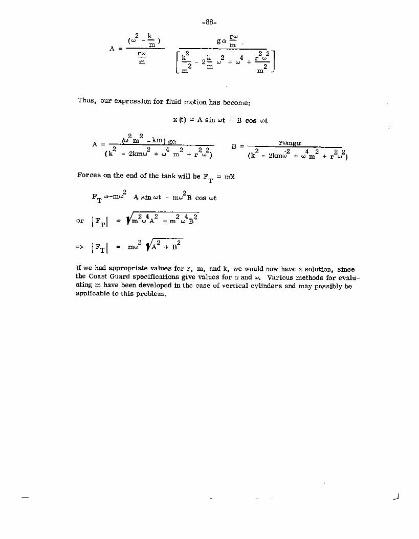
Thus,ourexpressionforfluidmotionhas
mA J
become:
x(t) =Astiut+Bcosut
~2~2A= -km)g~
B= rurnga(k2 - 2kmti2+ ti4m2+ r2u2) (k2- 21Cm~2+ u4m2+ r2w2)
ForcesontheendofthetankwillbeFT= fi
2 2‘T =-mu Asinut - mmB COStit
or FT =
=> ‘T =
Ifwehadappropriatevaluesforr, m, sndk,wewouldnowhaveasolution,sincetheCoastGuardspecificationsgivevaluesforaandu. Variousmethodsforevalu-atingmhavebeendevelopedinthecaseofverticalcylindersandmaypossiblybeapplicabletothisproblem.
-J

-89-
REFERENCES
A-1. Codeof FederalRegulations,Revisionof1January1968,Title46,Parts1-146.
A-2. ADescriptionoftheTheoryandOpera-tionoftheSurfaceShipMotionsComputerProgramNumber0344,R.C. Uhlin,ElectricBoatdivisionReportU411-68-020,April1968.
A-3. FundamentalsoftheBehaviorofShipsinWaves,IR.G.Vossers,PublicationNo.151aoftheN.S.M.B.
A-4. “TheRollingandPitchingofaShipatSea.ADirectComparisonBetweenCalculatedandRecordedMotionsofa ShipinSeaWaves,‘‘ D.E. CartwrightandL.J. Rydill,InstituteofNavalArchitects,Vol.99No.1, January1957.
A-5. OceanWaveStatistics,HogbenandLumb,1967Edition,A-6. PrinciplesofNavalArchitecture,J.P. Comstock,Editor,SNAME,1967.A-7. InvestigationoftheNaturalFrequenciesof FluidsinSphericalandCylindrical
Tanks~J. L. McCartyandD.G. Stephens,NASAT.N. D-252,May1960.
A-8* A“MonographonTestingforBoosterPropellantSloshingParameters,D.M.Eggleston,ConvairDivisionReportGDC-BTD67-089,June1967.
A-9. MeasurementsoftheUnsteadyForcesActingonaCircularCylindricalTankContainingLiquidDuringHarmonicMotion,P.R. Guyett,R.A.E. TR67098,April1967.
L.

-90-
AppendixB
ANALYSLSOFRINGSTIFI?ENERS
Analysisofcircularringssubjecttoappliedsupportloadsandappliedtankandliquidweightloadswasperformed;1800saddlesupportsofwidthhwereassumed.Theloaddistributionontheringduetothesupportwasassumedtobepr = pl cos Ofor. .lfll~ 90°and Ofor90°40<270”. TheloaddistributionduetothetankandliquidweightwasassumedtohePO. p2sinO(seefigureB-l). Thetotalsystemofappliedloads must be self-equilibrating. Assumingthat the ring widthquals the saddlewidth, h,
_2L‘1 = hir2r
and
where~ isthetotalloadsupportedbythesaddle.
Itisnecessarytoexpandthesaddleload,p , ina Fouriercosineseriestohavetheproperformforanalysis.Performingthe~ecessaryintegrationsyields:
I2Q ~+irPr=-— ~cos e+; ~cos4Qhr2r cos20-15
+~35COS6@-~cos 80+ :Coslo e-... I(B-1)
Theweightloading,PO,alreadyhastheformofthen = 1termofseries:
GP~”-— sinorrh82
FromFlugge‘-1 (p219,Eq.13a-c),settingPx= 0,~ S —aX2
governingdifferentialequationsoflinearthinshellbendingtheoryintermsofvandw,thecircumferentialandradialdisplacements
2C& dw ‘r3r .0dB2+iii+ D
aFouriersine
(B-2)
~ Oyieldsthe
forcircular-ringsrespectively
(B-3)
.>-
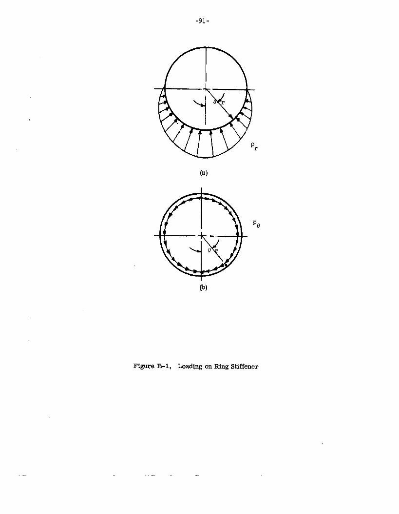
,_
-91-
(a)
F@ureB-1, Load@gonRingStiffener
.

where ==-(1-V2)
andk.&_
12r2
-92-
12d4w _+2d2w ●w ‘rr.—= od04 d62 D (B-4)
(B-5)
(B-6)
@nAppendixB, t refers tostiffenerthickness,i.e., outerradiusminusinnerrzdius.)
Differentiationofeq. B-2withrespectto13andsubtractionofeq. B-1fromthere-sultyields:
C&v+d05
Substitutionofeqs.
+*=& [& (Pr)+ PO1 (B-7)‘o ‘D
B-1andB-2forprandPOgives:
$sinz9+fi sin40
Let w be aFouriercosineseries:m
W=z WnCosI1on=o
(B-8)
(B-9)
Differentiationofeq. B-9, substitutionintoeq. B-8, andequatingcoefficientsofthesametrigonometricfunctionsyieldsthefollowingsolutionforw. (NotethatW.isdeterminedfromeq. B-4.)
~ (~)+: (~) [--$ cos2ew = - D;l+k)
+~2Cos40 2-—cos69 + — COS 80
(15)3 (35)3 (63)3
2_— Cosloo...(99)3 1
Similarly,assumev isa Fouriersineseries:
(B-1O)
—. —

.93.
Differentiationofeqs.B-1OandB-11,substitutionoftheseresultsandeq.B-2intoeq.B-3,andequatingcoefficientsofthesametrigonometricfumctionsyieldsthefollowingsolutionforw
() ( )[2 g sfi6+&2Q,~=. c 1D hrr kD — sinZe
h?r2r (3)31 Cos48 + 1 1-— sin60 - Cosse
(2)(15)3 (3)(35; (4)(63)3
1+— Cosloe-.. .1 (B-12)
(5)(99)3
FromFltigge(p214,eq9a-h),thecircumferentialforceandmomentresultantsintermsofv andwdisplacementsare:
.O=:(*+.) +; [’+$1
Me . ‘—[1
w+d~r2 d02
whereEt3K= ~
(B-13)
(B-14)
(B-15)12(1-V4)
Substitutionofeqs. B-10andB-12forv andwintoeqs. B-13andB-14yield:
+~2 2
COS 60 - — COS 80 + — Cosloe-... 1(E-16)(35)2 (63)2 (99)2
M@. - ‘2(?!%),p [$ .0s2, - ~ .0s4012r2+t2h~
+~2 2
COS 60 - — Cosse -1-— Cosloe-.. .1(B-17)(35)2 (63)2 (99)2
Thecircumferentialstressintheringattheinnerandoutersurfacesisgivenapproxi-matelyby
(B-18)
—
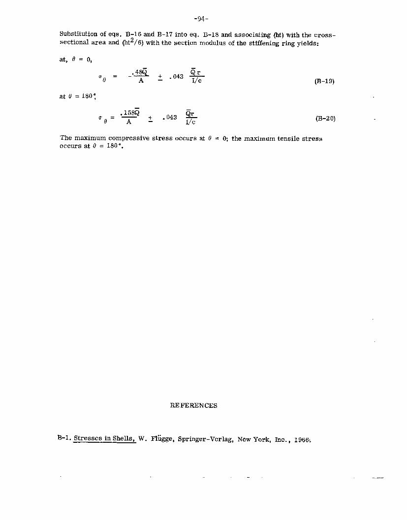
-94-
Substitutionofeqs.B-16andB-17intoeq.B-18andassociating(M)withthecross-sectionalareaand(ht2/6)withthesectionmodulusofthestiffeningringyields:
at,0 = (),
_.~ + ‘r‘e = .043$ (B-19)
at0 =180:
,158zj● 043 $ (13-20)
Themaximumcompressivestressoccursat6 = O;themaximumtensilestressoccursatO= 180°.
REFERENCES
B-1.StressesinShells,W.Fliigge,Springer-Verlag,NewYork,Inc., 1966:

-95-
AppendixC
OUTLINEFORSTFWNGAGEINSTRUMENTATIONOFATANKBARGE
C.1. INTRODUCTION
Generally,strainrecordinginstrumentsareusedtodescribestrainmagnitude,direction,anddistributioninareasofcomplexstructureswhichmaynotbereducibletomathematicaldescription,or toverifythepresenceandmagnitudeofcertainstrainswhichhadbeenpredictedbytheoreticalanalyses.
Themainobjectivehereis tadescribe,ingeneralterms,presentlyavailablein-strumentationproceduresapplicabletoanexperimentalstressanalysisoflargetankssupportedandtransportedbybarge.
C.2. DISCUSSIONAsaprerequisitetotheinstallationofanyinstrumentation,thefollowinginformationisnecessary:
1.2.
3.4.
5.
6.
Typeoffluidwhichwillbecarriedduringthetest.Geographiclocationoftheworksiteandthetimeofyearproposedforin-stallation.Typeandavailabilityofelectricalpowerforsiteworkandtesting.Numberandsizeoftankpenetrationsavailabletopermitinternalinstrumen-tationinstallationandtheexitingofsignalloads.Totalnumberofinformationchannelstoberecordedandspecificlocationsatwhichstraingagesandothertransducersarerquired.Durationofthetestprogram.
Thefollowingtestconditionsarerepresentativeoftheexperimentalprogram1. Strainda~willberecordedduringfillingandemptyingoftheti or tanks.2. Straindatawillberecordedduringactualoperationof‘thebargeinsea
statesif thebargeselectedisforoceanservice.3. Bow-slamming,heaving,twisting,andpitchwillberecordedasafunction
ofstrain,pressuredistribution,accelerationsandtime,relativetoseastateandfomvardvelocityifthebargeisforoceanservice.
4. Straingageandtransducerdatawillberecordedusingdynamicsinstrumen-tation.
C.3 GENER4LAREASOFINTERESTGeneralareasof interesthavebeenidentifiedandshownonfigureC-1. Straingageswillbeapplied,bothinternallyandexternally,intheareaofthesupportsaddle.Measurementsofstraindecaybetweensaddlesupportswillbeobtainedbyanarrayofstraingagesontheinnerandouterskinofthetank.

-96-
FigureC-2indicatesthegeneralareasofinterestonthebargehull. Pressuretrans-ducers,velocityandaccelerationinstruments,andstraingageswillbeusedtoobtainanunderstandingoftheforcesactingonthebarge/tankduringactualoperation.
C.4 PROPOSEDINSTRUMENTATIONTosimultaneouslyrecorddynamicdatafroma largenumberof signalsources,multichannellightbeamoscillcigraphsor taperecordersmaybeused.Thesedevicesrecordaprocessedorconditionedsignalwhichisdevelopedbyperipheralequipment.Ingeneral,thefollowingequipmentisneededtoobtainanintelligiblesignalfromastraingageorothertypeoftransducer:
1. Powersupply2. Amplifierandsignalconditioner3* Recorder4. Interconnectingcable.
C.5 TESTFACILITIESANDCONSIDERATIONSsincea testofthistyperequiresconsiderabletimeandexpen8e,adequatefacilitiesarerequiredtoprotectexpensiveequipment.Asuitablestructure,centrallylocatedwithrespecttoheavilyinstrumentedareas,canreducetheamountofcableusedandresultinasignificantreductionininstallationcosts. Thepossibilityofmorethanonerecordingstationshouldbeconsideredifheavilyinstrumentedareasareseparatedbyahundredfeetormore. Secondary,unmannedrecordingstationscanbesyn-chronizedtothemainrecordingstationoroperatedindependently.
Animportantconsiderationinthecostevaluationofmultichanneldynamicrecordingsystemsisthefrequencylevelwhichthesystemmustrespondtoandrecord.ThefrequencylevelwillbewithinOto50Hz. Theoutputsignalfromastraingagemaybedirectlyrecordedbycertainlightbeamoscillographswithoutamplification,thuseliminatingoneofthecostlycomponentsoftherec~rdingsystem.However,ade-cisiontodowithoutamplificationmustbejustifiedbytheoreticalanalysis.
Finally,itis importanttohaveaclearunderstandingofthetypeofdataobtainablefromstraingages.Ifasingle-elementstraingageisusedatapointofinterest,thestraindatadoesnotpermitacalculationofthemaximumprincipalstressunlessthestrainfieldisamaximumanduniformlyuniaxialinthedirectionofthegage,suchaswouldoccurinacontrolledtensilespecimentest.
Atwo-elementorbiaxialstraingagemaybeusedtocalculatemaximumandminimumprincipalstressesatthepointofinterestwhenthebiaxialgageorientationis identicaltathebiaxialstrainfield.
Athree-elementstraingagewillallowmaximumandminimumprincipalstressesanddirectionstobecalculatedfromrawdataforthepointofinterestwithouttheneedforspecificorientationwithrespecttathetestspecimenptrainfield.
Hence,thethre-elementstraingage(triaxialstrainrosette)is mostsuitabletodetermineprincipalstressesanddirectionsinstructuressubjecttocombinedloading,suchastwistingmdbending.
— -1
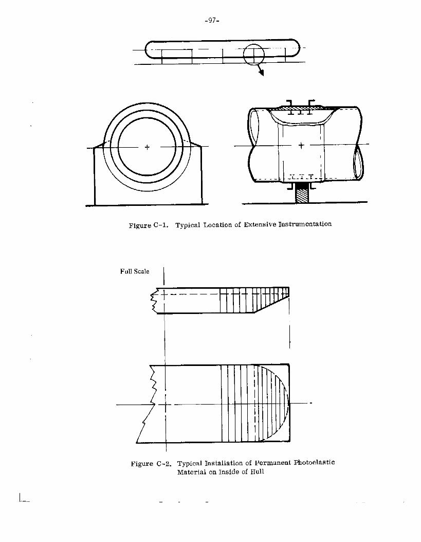
-97-
a
1l—
—
I
FigureC-1. TypicalLocationofExtensiveInstrumentation
FullScale II
1
I
I
FigureC-2. TypicalInstallationofPermanentMaterialonInsideofHull
— —
-.
Photoelastic

-98-AppendixD
DISCUSSIONOFAPPROACHFORTANK/%AItGESIAMMINGMODELTESTS
D.1 PROPOSEDBOWPRESSUREMEASUREMENTSINWAVESThisdiscussionoutlinesaprogramofbargemodelfabricationandtowingtestsinvariousregular,sinusoidalwaveconditions.Thepurposesofthetestsaretameasurethebowimpactpressuresandnormalvelocitiesandtodefinethepitchingandheavingamplitudesofthebarge.Duringtheprogram,thetheoreticalpeakpressures,basedonthemeasurednormalvelocities,willbecalculatedandcomparedwiththee~eri-mentallydeterminedvalues.Completionofthisproposedprogramwillrequirethefollowingspecificitemsofwork
D.1.1 WOKSTATEMENT1. Fabricateonewoodenmiddlebody-afterbodybargemodeltaapproximately
1/25scale.Themodelwillprovidefortheattachmentofvaryingbowcon-figurationsandwillbefabricatedinaccordancewithlinessuppliedbythecustomer.
2. Fabricatethreeseparatewoodenbowconfigurationstothesamescaleasthemiddlebody-afterbodymodelofItem1inaccordancewithlinessuppliedbythecustomer.
3. Installtowingstaffandpitch,heave,andverticalaccelerationinstrumentationinthemiddlebody-afterbodysection.Installninecrystal-typepressuretrans-ducers,andnormalvelocityinstrumenbtioninthebowsection.Normalvelocitieswillbeobtainedbyelectricallyintegratingverticalaccelerationmeasurements.
4. Ballasteachmodelh thepredicteddisplacements(lightandheavy),centerofgravitypositions(longitudinalandvertical),andlongitudinalradiiof~ration.Calibratealltestinstrumentation.
5. Conducttowingtestswitheachmodelattwodifferentdisplacementsandatonevelocityintowavesoffourdifferentscaleheights.Testswillbeconductedinsixdifferentwavelengthsforeachwaveheight.Approximately144testswillberequired.Timehistoriesofthewaterimpactpressuresatninestations,normalvelocitiesatthreelongitudinalstations,verticalaccelerationsatbowandcenterofgravity,pitchangles,heavedisplace-ments,towingvelocity,andwavecontmmswillberecordedsimultaneouslybyaminimumoftwooscillographicrecorders.Thetimereferencesofthetworecorderswillbepreciselycorrelated.
6. Reducealltestdatatoengineeringtits andexpandtofull-scaleproportions.
7. Usingthenormalvelocitiesoccurringateachpressuretransducerlocationduringtheinstantofpeakpressure,calculatethetheoreticalmaximumimpactpressureusingmethodsdescribedinreferencesD-1andD-2.
8. Preparegraphicalpresentationsofthepeakimpactpressures(measuredandcalculated),pitchandheaveamplitudes,normalvelocities,andvertical

-99-accelerations.
9* Prepareandsubmitamodeltestreportpresentingthetestandtheoreticalresults,representativetestphotographs,anddiscussionsofthetestingtechniques,instrumentation,andresults.
D.2 SLAMMINGThefollowingcommentsaremade concerningthediscussionofslamming.
1. Itwillbeuseful,whilemakingslammingtests,toinvestigatethefollowinga. Effmtofon-boardfluitiontaintngtanks.b. Effectofsurgeduetotowingbyasurgingtug.
2. ThemethodofstaticstrengthdesignisconcernedmainlywithseaplanedeEignpracticewhichmayproveadequate.
D.3 DEC~SIONTheDTMBReportNo.1994(referenceD-3)hasbeenreviewed,aswerereferencesD-1,-2, -4 and-5. WebelievethattherisetimeanomaliesfoundinTable3ofreferenceD-3areamanifestationofthetrappedairproblemdiscussedinreferencesD-1mdD-4. Also,theirinstrumentationsystemfrequencyrespmwe(1200Hz)wasrelativelylowcomparedtothesystemresponse(200KHz)describedinreferenceD-1.
Systemresponsesof200KHzrequiretheuseofcathoderayoscilloscopesandstreakcamerasfordatarecording.Theuseofthisequipmentonourtowingtankcarriageisnotfeasible,particularlyinviewofthefactthatwewouldbeinterestedinnineseparatepressuremeasurements.However, wecanachieve-5000HZsystemresponseutilizingoscillographrecordingtechniques.Itisproposed,therefore,thatthebowpressuresatninespecificlocationsbemeasuredbycrystal-typepressuretransducerswith200KHzfrequencyresponseandrecordedbyoscillographsincorporatinggalvan-ometershavingfrequencyresponsesof 5000”HZ. Thus, an overall system responseof 5000HZwillresult.Crystal-typetransducersaredesirable~ecauseoftheirsmall(O.20Sinch)diameterpressurefaceandlowsensitivitytoaccelerationforces.Itisanticipatedthatmaximumfull-scalebargenormalvelocitiesof10to20fpsmaybeincurredinwaves.Sinceabargeis relativelylightlyloaded,thebowwillnotcutthroughthewaterandmaybeexpectedtodeceleratesignificantlyunderthegrowingpressurearea.Inanyevent,Wagner*suggeststhattheoutboardedgeofthewettedwidthsweepsoutward4ataspeed,
VNc=—
p(c)
wherethefunctionp(c)isgivenbyapowerseriesfornon-wedgeshapes,andby~tanp forwedges.
*Germanmathematician

-1oo“Thus,foranarbitraryhulldeadriseof20andafull-scalenormalvelocity,V of15fps,theresultingspeedis N’
.c=;x15x- 0.0309 x 12=9,150in./seefullscale
Thepointvalueofthepeakpressurewould,therefore,remainonaO.208inchdiameterpressuretransducerfor23microseconds~orthefull-scalecase,and115microsecondsfora1/25thscalemodelwithFroudescaling.A5000Hzsignalhasaperiodof200microseconds,whichisequivalenttoaquartersinewaverisetimeof 50microseconds.Thus,a zerowidthpeakpressurecorrespondingtatheaboveexamplecouldconceivableybemeasuredatmodelscale,butnotfullscale.Whatthepressurepickup“measures‘‘ isdependentuponthewidthofthepressurepeakaswellasuponthespeedwithwhichittraversesthepickupdiameter.Anexampleofthevariationofthiswidthwithwedgedeadriseis showninfigureD-1,whichisareproductionofafigurefromreferenceD-2.
Lnviewoftheabove,it is furtherproposedthat thepeakpressuresbecomputedbythe methodsofreferencesD-1, D-2, andD-5for comparativepurposes.Tofacilitatethesecomputations,thenormalvelocitiesincurredduringimpactwillbemeasuredatthethreelongitudinalbargestations,correspondingtothethreetransverselinesofpressuretransducers,byelectricallyintegratingtheverticalac-celerations.Thepressuremeasurementswillberecordedsirnultaneouslywiththenormalvelocitymeasurementsonthesameoscillographtapeandwill,therefore,becorrelatedbytheprecisiontimereference.Thenormal velocityattheinstantofpeakpressureateachpressurestationcantherebybeobtained.
Duringeachmodeltest,measurementsofthebargepitchingandheavingamplitudesandtheverticalaccelerationsatthebowandcenterofgravitywillbeobtained.Also,recordingsofthetowingvelocityandthewavecontours(measuredoutboardofonespecificbargestation)willbeobtainedduringeachtest.
Itis believedthatthis combinedmodeltest datawillfullydescribetheeffectsofwaveimpactsonthevariousbowconfigurations.
Oncethis data hasbeenobtained,theproblembecomesoneofestablishingtherelationbetweenstaticstrengthdesignandthehighlytransientloadingsimposedbylowdeadriseimpacts.Ourpastexperiencewithfull-scaleseaplanesoperatinginwaveshasbeenthatthemaximummeasuredpressuresarefarinexcessofthosewhichthebottomplatingcouldsustainstaticallyoveranysignificantarea. ItmaybeofinterestthatoneoftheauthorsofreferenceD-5laidthefoundationin1947fortheapproachofreferenceD-6. Thisisa methodwhichstillfindswideusetodayonhydrofoilsaswellasseaplanes.Itisbelievedthatasimilarcorre~tionofstructural‘~successes~~and“failures”withtheorymayberequiredforbarges.
—
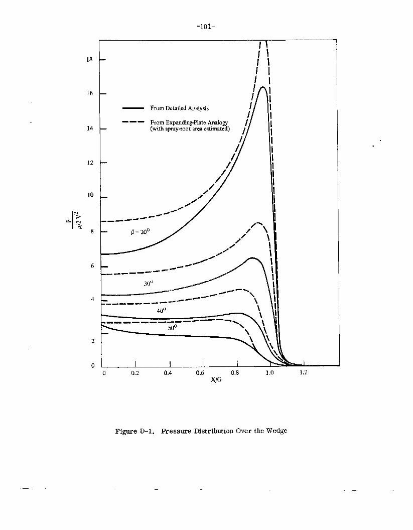
18
16
14
12
10
6
4
2
-1o1-——
IIIIIIii
II/rI— FromDetailedAualysis I
/- —— FromExpanding-PlateAnalogy
//(withspray-rootareaestimated) /
40° \.-- —- ----- ---—- >
~ LL--1 I0 I0 0.2 0.4 0.6 0.8 1.0 1.2
X/G
FigureD-1. PresswreDistributionOvertheWedge
.—

-1o2-REFERENCES
D-1. JournalofShipResearch,Vol.11, No.3, September1367.
D-2. “ThePenetrationofa FluidSurfacebyaWedge”,JohnD. Pierson,StevensInstituteofTechnologyReportNo.381,July1950.
D-3. “Two-DimensionalExperimentsontheEffectofHullFormonHydrodynamicImpact”,MargaretD. OchiandFrankM.Schwartz,DavidTaylorModelBasinReport1994,May1966.
D-4. Journal of ShipResearch. Vol. 11, No. 4, December1967.
D-5. “ATwo-DimensionalStudyof the Impactof Wedgeson a WaterSurfaceforthe BureauofAeronautics”, R. L. Bisplinghoffand C.S. Doherty,MassachusettsInstitute of Technology,Departmentof AeronauticalEn-gineering, ContractNo. NOa(s)-9921,March20, 1950.
D-6. MilitarySpecification,AirplaneStrengthand RigidityWaterand Handlingbads for Seaplanes, MIL-A-8864(ASG),18May1960.

UNCLASSIFIEDSecurityClassification
DOCUMENT CONTROL DATA-R&D(SewrityClase.,ficationof titln, body of sbstract and indexing annotationmust bo ontereclwhen the overall report IS classified)
1. ORIGINATINGG AcTIUl?Y (Co.-por#te aufhor)GeneralDynamicsCorporation
28. REPORTSECURITYCLASSIFICATIONUnclassified
ElectricBoatDivision zb GROUP
1. REPORTTITLE
STRUCTURALDESIGNREVIEWOFLONG,CYLINDRICAL,LIQUID-FILLEDINDEPENDENTCARGOTANK-BARGES
!DESCRIPTIVENOTES(Typedmpd .sndinchsiwdates)
FinalReport5.AUTHOR(S)(Lasfname,firsr name, initial)
Bascom,C.W.
;.REPORTDATE 7a. TOTALNO.OF PAGES 7b, NO, OF REF5
May1970 102 27ja. CONTRACTOR GRANT NO. 9=. ORIGINATORS REPORT NUMBER(S)
NOO024-68-C-5419 U413-68-125b. PROJECT NO,
SF013-03-04;Task2022,SR-184c. 9b. OTHERREPORTNO(S)(Anyoth.rnumbersthetmaybeaaaigned
thisreport}
d. SSC-205I10,AvAILABILITY/LIMITATIoN NOTICES
Distributionofthisdocumentisunlimited.
Il.SUPPLEMENTARYNOTES 12.SPONSORINGMILITARYACTIVITYNavalShipSystemsCommand
II13,ABSTRACT
Thisreportdescribesa programofanalyticalresearchtodeterminetheavailabilityofreliablemethodsforthedesignoflong,largediameter,cylindrlca”tanksandtheirsupportsfortransportationofliquidsandlow-pressureliquifiedgasesin barges forservice on rivers or at sea. Loading conditions, existingdesign/arialysiSmethods, material considerations,and a computer method forpredictingstressesarepresented.
Themajorconclusionoftheworkperformedisthatdesignproceduresforriverbargetanksupto20feetindiameterarewellestablishedandthatnofailuresduetoinadequatedesignpracticehavebeenreportedsincerefrigeratedtankswentintoserviceabouttenyearsago.Thepresentmethodfordesigningriverbargetanksisa logicalstartingpointfordeterminingthestructuralconfigurationoflargetanksforoceanicservice,butmoredetailedanalysisofloadsandresultingstressesshouldbeperformedforthisapplication.
Severalareasinwhichtheoreticalorexperimentaleffortisneededareidentified:(1) investigationoftank-saddle-bargeinteraction,(2) investigationoffatiguecriteriaforcyclicloading,(3) investigationofbucklingcriteria,(4) analyticalandexperimentalinvestigationofslamming,and(5)experimentalverificationofstressesina full-scaletank.
&
DD,W%1473 UNCLASSIFIEDSecurityClassification
— — —.

SecurityClassification4. KEYWORDS
INSTRUCTTONSL ORIGINATINGACTIVITY.Enterthenameandaddressof thecontractor,subcontractor,~rantpe,DepartmentOfDE+fenseactivityorotherorganization(corporateauthor)issuingthereport.2a. REPORTSECUHTYCLASSIFICATION.Entertheover-all securityclassificationof thereport.Indicatewhether“RestrictedDate” is included Markingis to be in accordantewithappropriatesecurityregulations.2b. GROW Automaticdowngradingis specifiedin DoDDi-rective5200.10andArmedForcesIndustrialManual.Enterthegroupnumber.Also, whenapplicable,showthatoptionalmarkingshavebeenusedforGrouP3 andGroup4 as author-ized.3. REPORTTITLB. Enterthecompletereporttitlein allcapitalletters. Titles in all cases shouldbe ~classified.If a meaningfultitlecamotbe selectedwithoutclassifica-tion,showtitleclassificationin all capitalsinparenthesisimmediatey foilowingthetitle.4. DESCRIPTIVENOTES If appropriate,enterthetypeofreport,e.g., interim,prowess, s~mmw, ~n~ufJror final.Givetheinclusivedateswhena specificrePortingperiodiscovered.5. AUTHOR(SIEnterthename(s)of authotis)as shownonor inthereport.Entm1astname,ffist Dame,mid~einitial.If military,showrankandbranchof service. ThenameOftbeprincipalauthoris anabsoluteminimumreq~rem@n~6. REPORTDATE Enterthedateof thereportas day,month,year;ormonth,year. If mOrethanonedateaPPearsonthereport,usedateof publication.7s. TOTALNUMBEROFPAGES Thetotalpagecountshouldfollownormalpaginationproced~es,i.e., enterthenumberof pagescontatiinginformation7b. NUMBEROF REFERENCESEnterthetotalnumberofreferencescitedinthervort.8a. CONTRACTORGRANTNUMBERIfappropriate,entertheapplicablenumberof thecontractor wantunderwhichthe report was written.8b,SC,&Ed.PROJECTNUM9ER.Entertheappropriatemilitarydepartmentidentification,=.uchaswOjeCtnumber,subprojectnumber,systemnumber%tasknumber)etc.9a. ORIGINATOR’SREPORTNUMBER(S):Entertheoffi-cial reportrmmberby whichthedocumentwillbe identifiedandcontrolledby the originating activity. This numberQstbe uti queto thisreport.9b. OTHERREPORTNUMBER(S):If thereporthasbeenassignedanyotherreportnumbers(e~fherby fheoriginatororbythesponsor),alsoenterthisnumber(s)-1o.AVAILA131LITY/LIMITATIONNOTICESEnteranylim-itationsonfurtherdisseminationof thereport,otherthanthos~
LllROLE
A‘#T
LINK❑ROLE WT
LllROLE
cWT
imoosedby securityclassification,usingstandardstatementssu~has:
(1)
(2)
(3)
(4)
(5)
“QualifiedrequestersmayobtaincopiesOfthisreportfromDfJG”,#ForelW announcementanddisseminationOft~sreportby DDCis notauthorized.”,,u, s. Governmentagencies mayobtaincopies‘fthisreportdirectlyfromDDC. OtherqualifiedDDCusersshallrequestthrough
.1,,,U. s, ~litary agencies mayobtaincopiesof thisreportdirectlyfromDDC Otherqualifisdusersshallrequestthrough
,,,
“AU distributionof thisreportis controlled.@al-ifiedDDCusersshallrequestthrough
, ,,
If thereporthasbeenfurnishedto theOfficeof TechnicalServices,Departmentof Commerce,for saleto,thepublic,indi-catethisfactandentertheprice, if knowm11. SUPPLEMENTARYNOTES Useforadditionalexplana-torynotes.12. sPONSORINGMILITARYACTIVITY Enterthenameofthedepartmentalprojectofficeor laboratorysponsoring(Paring for) theresearchanddevelopment.Includeaddress.13. ABSTRACT:Enteranabstractgivinga briefandfactualsummaryof thedocumentindicativeof thereport,eventhoughit mayalso 3ppearelsewhereiIIthebOdyOfthetechnicalr@-port. If additionalspaceis required,a continuationsheetshalbe attached.
Itis highlydesirablethattheabstractof classifiedrePOfibe unclassified.Eachparagraphof theabstractshallendw“ithanindicationof themilitarysecurityclassificationOfthein-formationin theparagraph,representedas (TS),(s), (c). orW.
Thereis no limitationon thelengthof thenbstract.How-ever,thesuggestedlengthis from150t~ 225words.
14, KEYwORDS:Keywordsaretechnicallymeaningfulte~$or shortphrasesthatcharacterizea reportandmaybe usedaSindexentriesforcatalogingthereport.Keywordsmustbeselectedso thatno securityclassificationis required.~denti-fiers,suchas equipmentmodeldesignation,tradename,mi~itaprojectcodename,geographiclocation.maybe usedaSkeywordsbutwillbe followedby anindicationof technicalcon-text. 77he assignmentof links,ralcs,andwei~htsis optional.
UNCLASSIFIEDSecurityClassification
— — .-—,,
SHIP RESEARCH COMMITTEEMaritime Transportation Research Board
Division of EngineeringNational Academy of Sciences-National Research Council
N%i.s prog’ec?thas been conducted under the guidance of Adui.SOYZ$Group 1.[,.sh.i.ph’t?search Connni.tte?e.The (!omrnittee has cognizance >f ShipStrueturw Conrnititceprojectsin materials, design and fabrication as reLating 10 ir,~provedship ztwc turea. This
responsibility entaik r~ecormwzdir,g research ob,je~-tives,tuses,
prepax,i~gproject prOspec-evaluating proposals, providing liaison atidtechwica1 gutdance, revieui.w?
project reports, and stimulatiry productive avenues of research.
Mil,M. L. SELLERS, ChairmanNaval ArchitectNewport News Shipbuilding
and Dry Dock Company
DR. H. N. ABRAMSON (1,11)Director, Dept. of Mechanical SciencesSouthwest Research Institute
MR. W. H. BUCKLEY (1,11)Chief, Structural Criteria and LoadsBel1 Aerosystems Co.
DR. D. P. CLAUSING (III)Senior Scientist, Edgar C. Bain
Laboratory for Fundamental ResearchU.S. Steel Corporation
MR. D. P. COURTSAL (11,111)Project ManagerDravo Corporation
MR. A. E. COX (1,11)Senior Program ManagerNewport News Shipbuilding
and Dry Dock Company
MR. J. F. DALZELL (I), CoordinatorSenior Research ScientistHydronautics, Incorporated
DR. w. D. DOTY (III)Senior Research ConsultantU.S. Steel CorporationApplied Research Laboratory
MR. F. D. DUFFEY (III)Welding EngineerIngalls Shipbuilding Corporation
PROF. J. E. GOLDBERG (1,11)School of Civil EngineeringPurdue University
MR. J. E. HERZ (1,11)Chief Structural Design EngineerSun Shipbuilding and Dry Dock Company
MR. G. E. KAMPSCHAEFER, JR. (III)Manager, Application EngineeringARMCO Steel Corporation
PROF. B. R. NOTON (II)Department of Aeronautics
and AstronauticsStanford University
MR. W. W. OFFNER (111)Consulting Engineer
PROF. S. T. ROLFE (III), coordinatorCivil Engineering DepartmentUniversity of Kansas
PROF. J. WEERTMAN”(II,III)Walter P. Murphy Professor
of Materials ScienceNorthwestern University
CDR R. M. WHITE, USCG (1,11)Chief, Applied Engineering SectionU.S. Coast Guard Academy
PROF. R. A. YAGLE (11), CoordinatorDepartment of Naval Architectureand Marine Engineering
University of Michigan
coR D. FAULKNER, RCNC (I,II)Staff Constructor OfficerBritish Navy Staff
(I) = Advisory(11) - AduLsvq
(1~1) = Advisory
MR. R. W. RUMKE, Execwtive SecretaryShip Research Committee
GPoup I, Ship .StrainMeasurement & .Analysistir[q 11, ship stm.lwtwl1 Uewiqn(;roupIII, Metallurgical Studies
SSC-191,
SSC-192,
SSC-193,
5~c_194,
SSC-155,
SSC-196,
SSC-197,
SSC-198,
ss~-lgg,
SSC-200,
SSC-201,
SSC-202,
SSC-203 ,
SSC-204.
and P. O.
!
,