
STRUCTURAL DESIGN OF FLEXIBLE CULVERTS … · STRUCTURAL DESIGN OF FLEXIBLE CULVERTS ... In Figure...
14
ARCHIWUM INSTYTUTU INŻYNIERII LĄDOWEJ Nr 23 ARCHIVES OF INSTITUTE OF CIVIL ENGINEERING 2017 STRUCTURAL DESIGN OF FLEXIBLE CULVERTS DEVELOPMENT TRENDS 1 Lars PETTERSSON* Amer WADI**, Kevin Williams*** *) Adj. Prof., Division of Structural Engineering and Bridges, KTH Royal Institute of Technology, Sweden **) PhD candidate, Division of Structural Engineering and Bridges, KTH Royal Institute of Technology, Sweden ***) Technical Director, Buried Bridges, Atlantic Industries Limited, Ontario, Canada Structural design requirements for flexible culverts are available in several interna- tional bridge design codes. Examples are the Canadian (CHBDC), the American (AASHTO) and the Swedish (TRVK Bro 11 2 ). The designation “flexible culvert” may today be somewhat misleading. The word culvert is usually associated with small pipes in road embankments. However, over the years flexible culverts have grown bigger and a more proper designation would be bridges. Therefore, these structures are often also referred to as Soil-Steel Composite Bridges or just Soil-Steel Bridges. With this devel- opment also new and more stringent requirements on the structural design follows. In this paper key aspects of a holistic design approach based on the authors experience on the essentials of flexible culvert structural design 3 are outlined and is compared to the current design approaches in the CHBDC and the TRVK Bro 11. However, this paper will provide insight into how the holistic design topics are addressed in current design codes and future research and development. Key words: Flexible Culvert, Soil‒Steel Composite Bridge, Canadian Highway Bridge Design Code, TRVK Bro 11, Swedish Design Method 1. INTRODUCTION General Corrugated flexible steel pipes are often used in road and highway construc- tion. By dividing the pipe into several curved plates and bolting those together at 1 DOI 10.21008/j.1897-4007.2017.23.22 2 The structural design requirements in the Swedish Bridge Code TRVK Bro 11 are based on the Eurocode. For the structural design of flexible culverts TRVK Bro 11 re- fers to [4]. 3 Note that this paper discusses structural design requirements only. Requirements related to the geometrical design, hydraulic design, durability, construction activities etc. also included in international bridge codes are not included in the paper.
Transcript of STRUCTURAL DESIGN OF FLEXIBLE CULVERTS … · STRUCTURAL DESIGN OF FLEXIBLE CULVERTS ... In Figure...

A R C H I W U M I N S T Y T U T U I N Ż Y N I E R I I L Ą D O W E J
Nr 23 ARCHIVES OF INSTITUTE OF CIVIL ENGINEERING 2017
STRUCTURAL DESIGN OF FLEXIBLE CULVERTS DEVELOPMENT TRENDS1
Lars PETTERSSON* Amer WADI**, Kevin Williams*** *) Adj. Prof., Division of Structural Engineering and Bridges,
KTH Royal Institute of Technology, Sweden **) PhD candidate, Division of Structural Engineering and Bridges,
KTH Royal Institute of Technology, Sweden ***) Technical Director, Buried Bridges, Atlantic Industries Limited, Ontario, Canada
Structural design requirements for flexible culverts are available in several interna-tional bridge design codes. Examples are the Canadian (CHBDC), the American (AASHTO) and the Swedish (TRVK Bro 112). The designation “flexible culvert” may today be somewhat misleading. The word culvert is usually associated with small pipes in road embankments. However, over the years flexible culverts have grown bigger and a more proper designation would be bridges. Therefore, these structures are often also referred to as Soil-Steel Composite Bridges or just Soil-Steel Bridges. With this devel-opment also new and more stringent requirements on the structural design follows. In this paper key aspects of a holistic design approach based on the authors experience on the essentials of flexible culvert structural design3 are outlined and is compared to the current design approaches in the CHBDC and the TRVK Bro 11. However, this paper will provide insight into how the holistic design topics are addressed in current design codes and future research and development.
Key words: Flexible Culvert, Soil‒Steel Composite Bridge, Canadian Highway Bridge Design Code, TRVK Bro 11, Swedish Design Method
1. INTRODUCTION
General Corrugated flexible steel pipes are often used in road and highway construc-
tion. By dividing the pipe into several curved plates and bolting those together at
1 DOI 10.21008/j.1897-4007.2017.23.22 2 The structural design requirements in the Swedish Bridge Code TRVK Bro 11 are
based on the Eurocode. For the structural design of flexible culverts TRVK Bro 11 re-fers to [4].
3 Note that this paper discusses structural design requirements only. Requirements related to the geometrical design, hydraulic design, durability, construction activities etc. also included in international bridge codes are not included in the paper.

238 Lars Pettersson Amer Wadi, Kevin Williams
the construction site the problem of transporting larger structures could be over-come and the concept of multi-plate structures was born. This new concept, first introduced in the 1930’s, made larger spans possible and today structures with spans over 20 m are being built.
Larger span flexible pipes or culverts as they are often referred to, have been used not only for water passages through road embankments but also frequently as bridges to carry roads or railways. In Figure 1 a 12 m span box culvert used as a road bridge in Sweden is shown. In many instances roads or railways are also carried through the culvert itself.
This development naturally set the focus on the structural design of the larg-er structures. The term flexible culvert is today somewhat misleading and these structures are instead often referred to as Soil-Steel Composite Bridges or just Soil-Steel Bridges.
Figure 1. 12 m span box culvert in the northern part of Sweden built in 2008.
The Ring Compression Method As early as the 1940’s the concept of flexible pipe supported by a surround-
ing soil mass was introduced. Through research and field experience of many successful culvert installations, ref. [1], it was clear that flexible culverts carry the load mainly through compression forces in the culvert wall. The conduit acts as a compression ring using the surrounding soil as support. Once this principle was established it was clear for designers and researchers that the quality of the surrounding soil is crucial for a well performing culvert installation. The soil should therefore be of high quality and frictional soil is the preferred choice for culvert bed, backfilling and cover soils.
Based on the experience and research available at that time White & Lay-er [2] introduced the ring-compression concept. White and Layer understood that the corrugated flexible metal conduit, achieves its load carrying capacity by in-teraction with the surrounding soil. When a load is applied at the top of the cul-vert, the top sinks and the sides move outwards and a soil pressure is mobilized. White and Layer realized that a well confined flexible ring is capable of carrying large concentrated loads and that effective compaction making the soil surround-

ing the pipthrough rment capations and
The ri
Figure 2. centrated
The riverificatiospan, contopographthe structu
StructuraIn Can
troduced culverts aCHBDC iCHBDC [
In Sw2000. Thethe ring-cSwedish bsign methtails in the
Both state desiforming s
4 In Swed
Structura
pe stiff, giveing compresacity to bridghandling stifing-compres
When confinloads. Unsup
ing-compreson of the strduit shapes, hy of the conural design m
al design codnada the Ontin 1979 whe
and was primintegrated an[3].
weden a desige current editcompression bridge code hodology to e developmethe Canadia
ign approachtructures.
den flexible culv
al design of fl
es an excellenssion, althouge unevenneffness. sion concept
ned the flexiblpported the loa
sion conceptructural capaheight of co
nstruction sitemethods to co
des for flexitario Highwaere it includmarily basednd supersede
gn methodoltion was prestheory is u
[5] the Swebe used in th
ent of the Swan and Swedhes and con
verts are referre
exible culvert
nt support fough they recoess in soil sup
t is illustrated
e ring carries ad carrying ca
ref. [2]
t is normallyacity of flexover, size, wee, etc. have nover structur
ble culvertsay Bridge De
ded a sectiond on the rin
ed the OHBD
ogy for flexsented in 20
used as the bdish Transpohe design of
wedish designdish design tain design
ed to as Soil-St
ts developmen
or the structurognized the pport, low he
d in Figure 2
both large disapacity is low,
y used in inteible culverts
eight and typnaturally incrres that can m
in Canada esign Code (n for the desng compressDC. The curr
ible culverts14 [4]. As inbasic designort Administf flexible culn methodologmethodologiapproaches
eel Composite
nt trends
re to carry loneed for beneight of cove
2.
stributed as we White & Lay
ernational cods. The develpe of the livereased the de
meet these tre
and Sweden(OHBDC) wsign of flexision theory. rent edition i
s was first prn the OHBDCn methodolotration requilverts4. For fgy (SDM), seies are basedresulting in
Bridges.
239
oad mainly nding mo-er installa-
ell as con-yer (1960),
des for the lopment in e loads, the emands on ends.
n was first in-ible buried The 2000
is the 2014
resented in C/CHBDC gy. In the
ire this de-further de-ee [6]. d on limit well per-

240 Lars Pettersson Amer Wadi, Kevin Williams
It is important to note that even if the requirements in the Canadian and Swedish design methodologies for flexible culverts are principally the same, the different requirements are formulated differently.
This paper discusses some development trends known to the authors and how these trends are covered in the buried structure structural design codes in Canada and Sweden.
It is noted that this paper focuses on the structural design; construction relat-ed aspects and requirements are not discussed. Additionally, the important as-pect of the environmental impact (from fabrication, construction, maintenance and end-of life) is not included in this paper but needs to be considered in the choice between different structure options. Other important aspects that need to be taken into account when designing flexible culverts and other types of bridges are resilience or robustness against, for example, a hydraulic event.
In Canada and Sweden requirements for the design of bridge and tunnel structures including flexible culverts are given in several codes and standards with references between them. These codes and standards are to be read togeth-er. Examples being loads and load factors, materials and material factors, steel and concrete standards, standards for backfill soil quality and compaction, re-quirements for scour protection, protection against soil migration etc.
Overall design in the preliminary, planning stages is not covered in this pa-per. Here several questions need to be answered for example how to meet the different requirements of the particular bridge site and achieve a sustainable and a resilient design for different unforeseen events.
2. SOME STRUCTURAL DESIGN ASPECTS
General The structural design methods for flexible culverts used in bridge codes in
Canada and Sweden are based on the same general ring-compression principle. Like White & Layer [2], the need for bending moment capacity is recognized and to enable calculation of bending moments from backfilling and live load, also the principles in the so called Soil Culvert Interaction (SCI) method (com-pare [7] and [8] respectively) are included in both design methodologies. Simi-larly, the corrugated wall buckling capacity is based on the same general princi-ple in both methodologies. The stiffness of the surrounding engineered frictional soil is expressed as a function of the soil gradation and degree of compaction in both design methodologies.
Full scale tests Full scale testing is very important for understanding the behaviour of the
flexible culvert structure under load. This is especially true for the behaviour in the ultimate limit state. Tests including loading the structure to failure are there-

Structural design of flexible culverts development trends 241
fore important. In Figure 3 a box culvert full scale test is shown. After measure-ments using the three axle truck shown in the figure, the structure was loaded to failure.
Fig. 3: Full scale test. Truck loading of an 8 m span box culvert
Several full scale tests having relatively large spans and including loading to failure have been performed in Europe and North-America in recent years. It is the recommendation of the authors that the results of these tests are reported in a coherent manner forming a platform for further development and refinements of current design methodologies.
Conduit shapes The conduit or arch shape/profile is important for adapting the structure to
different requirements at a specific bridge site. One example, the so called pipe arch, is shown in Figure 4. However, full scale measurements clearly show that the shape influences the forces in the culvert wall, compare for example ref. [9].
Figure 4. Pipe arch shape. The pipe arch shape is defined by three radii
A structural design methodology therefore need to be able to cover most of the commonly used profiles.

242
In SDflatter typdesign eqdesign mewhich utiprofiles.
New suggestedthey appe
DeflectionCondu
importantner, see Fheight of When desetc., this a
Figure 6may cause
GuidaCHBDC o
DM, ref. [4], pe of profilesquations by ethodology tilizes refined
Figure
shapes/profid that a well-ear, in the des
ns and deforuits are flext that the bacFigure 6. Thcover (espec
signing the baspect should
. Conduite he culvert to
will ca
ance for the cor SDM.
Lars Petter
the design s (for exampintroducing therefore difd analysis (F
e 5. The finish
les will sure-defined procsign equation
rmations ible and exp
ckfilling is pee peaking excially when bridge, for ed be taken in
t deflections dmove in an u
ause the culve
calculation o
rsson Amer W
methodologyle the box cua geometry
ffer somewhaFEM) to det
hed steel struct
ely be develcedure is devns available t
perience defoerformed in axperienced dthe cover is
example decinto considera
during backfilluncontrolled mert to peak, fro
of live load d
Wadi, Kevin W
y is developulvert, Figurfactor to th
at from the Ctermine secti
ture of a box c
loped in the veloped to intoday.
formations dua symmetricduring backfsmall) in th
iding on the ation.
ling Left: unsymanner. Right:om CSPI (200
deflections is
Williams
ped in such are 5) are covehe SCI equaCHBDC appional forces
culvert.
future. It isnclude new p
uring backfial and controfilling may r
he permanentfoundation
ymmetrical ba: symmetrical
02), [1].
not given in
a way that ered in the
ations. The proach [3],
for flatter
s therefore profiles, as
illing. It is olled man-reduce the t structure. elevations
ackfilling backfilling
n either the

Structural design of flexible culverts development trends 243
Settlements in the connecting road embankments being bigger than the settle-ments in the structure need to be carefully evaluated based on geotechnical borings since they may lead to so called negative arching with more load being transferred to the structure. Both CHBDC and SDM account for negative arching.
Other types of deformations need to be considered. For example the conduit may need camber in the longitudinal direction to compensate for long-term set-tlements which may reduce the free room in the culvert or the area available for water running through the conduit.
From a structural design point of view settlements in the longitudinal direc-tion of the fill above the conduit or of the conduit itself may lead to increased shear forces on the bolts in the connections as well as increased load effects in culvert footings (for arch/open shapes/profiles). FEM-analysis may be used to determine the forces and reactions in a more refined way.
Beveled ends (cut ends) In most designs the conduit has beveled ends comforming to the shape of the
road embankment. In Figure 7 an example of this is shown. Many codes have requirements for allowed geometries for the conduit ends. Further advancing the design criteria for bevelled ends can for example be helpful in developing de-signs where the flexible culvert is not perpendicular to the road line.
Figure 7. Flexible culvert having beveled ends
Design calculations where FEM is used can help in this respect. Using 3D FEM will make the design more complicated but the effect on the structure can be analyzed in more detail if deemed necessary, for example in unsymmetric cases.
Traffic (live) load Live load may have a significant effect on the conduit, especially in low
height of cover installations, Figure 8. The way to evaluate the normal force and bending moment induced by live
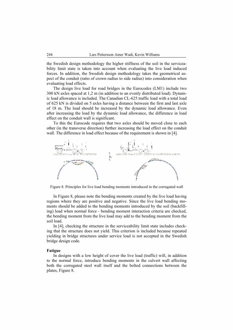
loads is well defined in both the Canadian and Swedish design methodologies. In
244
the Swedibility limforces. Inpect of thevaluating
The d300 kN axic load allof 625 kNof 18 m. after increeffect on t
To thiother (in twall. The
Figure 8
In Figregions wments shoing) load the bendinsoil load.
In [4]ing that thyielding ibridge des
Fatigue In des
to the noboth the plates, Fig
ish design mmit state is tan addition, the conduit (rag load effectsdesign live loxles spaced alowance is in
N is divided oThe load sh
easing the lothe conduit wis the Eurocothe transversdifference in
. Principles fo
gure 8, pleasewhere they arould be addewhen norma
ng moment f
, checking thhe structure in bridge strusign code.
signs with a rmal force, corrugated
gure 8.
Lars Petter
methodology aken into ache Swedish datio of crowns. oad for roadat 1,2 m (in ancluded. Theon 5 axles hahould be incoad by the dwall is signifode requires e direction) f
n load effect b
or live load be
e note the bere positive a
ed to the benal force - benfrom the live
he structure does not yieuctures unde
low height ointroduce besteel wall it
rsson Amer W
the higher sccount whendesign methn radius to si
d bridges in taddition to ane Canadian Caving a distacreased by thdynamic loadficant.
that two axfurther increabecause of th
ending momen
ending momeand negativeding momennding mome
e load may ad
in the serviceld. This criter service lo
of cover the ending momtself and the
Wadi, Kevin W
stiffness of thn evaluating hodology takide radius) in
the Eurocodn evenly dist
CL-625 trafficance betweenhe dynamic d allowance,
les should basing the loahe requiremen
nts introduced
ents created b. Since the l
nts introduceent interactiodd to the ben
ceability limierion is inclu
oad is not ac
live load (trments in the e bolted con
Williams
he soil in thethe live loa
kes the geomnto considera
des (LM1) intributed loadc load with an the first anload allowathe differen
e moved cload effect on tnt is shown i
d in the corrug
by the live lolive load bend by the soil
on criteria arending momen
it state includuded becauscepted in th
raffic) will, iculvert wall
nnections be
e servicea-ad induced
metrical as-ation when
nclude two d). Dynam-a total load nd last axle ance. Even nce in load
ose to each the conduit in [4].
gated wall
oad having nding mo-l (backfill-e checked, nt from the
des check-se repeated he Swedish
in addition l affecting
etween the

Structural design of flexible culverts development trends 245
In [4] a design methodolgy is presented for the designer to be able to verify the fatigue capacity of the corrugated steel plates themselves, the steel plates at the bolted connections and the bolts. The detail categories presented are based on testing at KTH, [10]. The test set-up used is shown in Figure 9.
Figure 9. Testing of the fatigue capacity of a bolted connection between two corrugated
steel plates in a laboratory at KTH, Stockholm.
It should be noted that the methodolgy in [4] is developed for Eurocode fa-tigue loads. It is possible however, to adopt the methodology to other fatigue load configurations.
Seismic design In Sweden seismic loads are not considered for bridges. Therefore the design
methodology for flexible culverts used in Sweden does not include seismic loads. CHBDC on the other hand include seismic loads and a design methodolgy to verify the structural capacity for such loads.
Sloping terrain If the terrain where the flexible culvert is to be constructed is sloping terrain,
this need to be taken into consideration when preparing the structural design. In [4] the slope perpendicular to the conduit has maximum allowed slope of 10%. The CHBDC does not comment on sloping terrain. The bending moment dia-grams in Figure 10 show the effect of increasing this slope to 30%. In addition the normal forces are increased. A study of the behaviour of flexible culverts in sloping terrain is presented in [11].

246
Figure 10The l
Of couhorizontalcritical crgitudinal account in
EvaluatinThe a
load for aimportanttherefore for exampconsidera
Figure 11low heigh
0. Bending moleft hand mom
urse a slope l, different se
ross section(sdirection pon the structur
ng existing sallowed live a long road st for road admit is importa
ple structuretion and may
. To the left: eht of cover. Th
Lars Petter
oment diagramment diagram a
along the cuections alongs). In a case ssible additioral design.
structures load for a
stretch. Therministrationsant that the ls having a vy require spe
existing flexibhe Scania truc
in
rsson Amer W
m in a pipe arcat 10% slope. at 30% slope
ulvert is alsog the conduitwhere the coonal forces i
specific struefore, load rs. A lot of fleoad rating pr
very low heigecial investig
ble culvert buick to the right
the culvert w
Wadi, Kevin W
ch culvert at dThe right han
e
o possible. At should be sonduit itself in the condu
ucture may drating of exisexible culverrocedure is rght of cover,gations, see F
ilt in Sweden was used to m
wall.
Williams
different grounnd moment dia
s long as thetudied to finhas a slope it should be
determine thsting structurrts have beenrational. Spe, need to be
Figure 11.
in the 60s havmeasure live lo
nd slopes. agram
e culvert is nd the most in the lon-taken into
he allowed res is very n built and ecial cases,
taken into
ving a very oad effects

Structural design of flexible culverts development trends 247
It can be concluded that design codes need to also include procedures for de-termining the capacity of existing structures where the input data for the verifi-cations are not always as well-known as for new structures.
High speed trains Railway lines for high speed trains are getting more common. Bridges in
high speed train lines need to be designed for the type of loads that the high-speed trains impose on the structures. Design methodolgies need to be developed that enables the designer to verify that the vibrations in the soil-structure system are kept with-in code requirements. This is true for flexible culverts as well as for any other bridge type. Studies that aim at developing such methodologies are presented in [12], see Figure 12.
Figure 12. High speed trains create ground vibrations. Studying the effect on bridges is therefore an important research topic also for flexible culverts. To the left full scale
test including measurements of deflections, steel strains and vibrations (structural as well as in the backfill soil). To the right a FEM-model developed with the purpose of calcu-
lating the structural response under high speed train loading, ref. [12].
Large spans Different sizes of corrugations are allowed in both the Canadian and Swe-
dish design methodologies. Corrugations with greater flexural stiffness, resist unbalanced forces from construction and live loading and are means to increase possible spans. It is believed the principles of a soil-structure design methodolgy are ”continuous” over the full range of corrugation sizes and stiffness without having to change or add design verifications depending on which corrugation size is used.
Although the culvert wall bending stiffness is expressed using EI in both the Canadian and the Swedish design methodolgies, deeper corrugations, being used in Canada in recent years (an example being the so called UltraCor), have not been used in Sweden so far.
However, studies are on-going to investigate if this stiffer type of corruga-tion is also covered by the Swedish design methodology or if some modifica-tions in the structural design methodology are necessary.

248 Lars Pettersson Amer Wadi, Kevin Williams
Figure 13. The world’s largest flexible culvert under construction in 2016 with
a span of 25,6 m.
Engineering skills as well as structural design requirements become very im-portant for the development of larger structures. For example the buckling ca-pacity and the soil behaviour at low heights of cover are important topics for more detailed studies. Load effects from both soil and live loads also need to be studied carefully.
Summary Some of the design aspects discussed above are included in Table 1 indicat-
ing whether a particular design aspect is covered/included in the Canadian and Swedish design methodology respectively. Note that the table only give exam-ples of structural design aspects.
Table 1. Some design aspects and the Canadian and Swedish design methodologies.
Design aspect Canadian design
methodology Swedish design methodology
1 2 3
Commonly used conduit shapes/profiles Several conduit profiles included
Several conduit profiles included
Beveled ends (cut ends) Covered – guideli-
nes only Covered – guideli-
nes only Backfill soil Frictional soil only Frictional soil only Design soil modulus based on backfill soil gradation and compaction.
Included Included
Requirements for min extent of engineered backfill zone
Included Included
Requirements for minimum height of cover Included Included Ultimate limit state verifications (i.e. buckling and plastic hinge formation)
Included Included
Ultimate limit state verification of the bolted connections
Included5. Included6
5 The seam capacity determined by testing checked against the shear forces created by the normal force. 6 Checked for the shear and tension and the combined shear and tension created by the normal forces and
the bending moments according to Eurocode principles.

Structural design of flexible culverts development trends 249
1 2 3 Serviceability limit state verification (on-set of yielding) during backfilling and under service loads.
Indirectly included Included
Fatigue verification procedure Covered – guidelines only
Included
Verification for seismic loads Included Not included Sloping terrain Not covered Not covered Existing structures, load rating Not covered Covered Backfill soil load Included Included Road live load Included Included Railway load (not high speed trains) Not included Included High speed train design methodology Not covered Not covered Avalanche load Not covered Not covered
3. Conclusions
The structural design methods for flexible culverts used in bridge codes in Canada and Sweden are based on the same general ring-compression principle. In addition, the principles in the so called Soil Culvert Interaction methodology are included in both codes. Similarly, the corrugated wall buckling capacity is based on the same general principle. Finally, the stiffness of the surrounding engineered frictional soil is expressed as a function of the soil gradation and degree of compaction. Both the CHBDC and SDM contain design approaches that have produced well performing soil-steel structures.
Both bridge codes allow for different conduit profiles. An important differ-ence between the design methodologies is that while the Swedish method in-cludes all the defined conduit profiles in the same general procedure the Canadi-an code has slightly different procedures for different conduit profiles.
Different sizes of corrugations are allowed in both CHBDC and SDM. Alt-hough the culvert wall bending stiffness is expressed using EI in both the Cana-dian and the Swedish code, so called deeper corrugations, being used in Canada in recent years, have not been used in Sweden so far. However, studies are on-going to investigate if also this stiffer type of corrugation is covered by the pre-sent methodology or if some modifications in the structural design methodology are necessary.
It is concluded that there are differences in the design requirements in Cana-da and Sweden. Furthermore design requirements in some cases are formulated differently and some structural design aspects are covered by one code but not the other. Examples of this being fatigue (covered by the Swedish code but not the Canadian), seismic (covered by the Canadian code but not the Swedish) and design for railway load (covered by the Swedish code but not the Canadian). None of the codes cover the effect of sloping terrain over the structure or high-speed train loading.
Both codes were developed aiming at covering most design situations. How-ever, there are still gaps that need to be filled. Research on-going in both Canada

250 Lars Pettersson Amer Wadi, Kevin Williams
and Sweden further advancing the knowledge in the flexible culvert structure is aimed towards covering these gaps (for example high speed train loading) mak-ing the flexible culvert a viable option for most bridge sites.
Acknowledgements This investigation was carried out at KTH Royal Institute of Technology Stockholm.
The authors extend their gratitude for the financial support from Atlantic Industries, ViaCon and KTH.
LITERATURE
[1] CSPI (Corrugated steel pipe institute). American Iron and Steel Institute. Handbook of Steel Drainage & Highway Construction Products. 2nd Canadian edition, Canada 2002 (2nd printing 2007).
[2] White L H, Layer P J. The Corrugated Metal Conduit as A Compression Ring. Highway Research Board. Proceedings of the 29th Annual Meeting, Washington, D.C. USA, 1960 (pp 389–97).
[3] CSA Canadian Standards Association. Canadian Highway Bridge Design Code S6-14. 11th ed. Canada: CSA Canadian Standards Association; 2014.
[4] Pettersson L, Sundquist H. Design of Soil Steel Composite Bridges. Report 112, 5th ed. KTH Royal Institute of Technology, Stockholm, Sweden 2014.
[5] TRVK Bro 11, Swedish requirements for bridges, Trafikverket (Swedish Transport Administration), TRV publ. 2011:085 (in Swedish), 2011.
[6] Pettersson L., Flener E. B., Sundquist H., Design of Soil–Steel Composite Bridges. Structural Engineering International 2/2015.
[7] Duncan, J. M., (1977), Behaviour and Design of Long-Span Metal Culvert Structures, ASCE Convention Soil-Structure Interaction for Shallow Foundations and Buried Structures, San Francisco, USA, October 1977.
[8] Duncan, J. M., (1978), Soil-Culvert Interaction Method for Design of Metal Culverts, Transportation Research Record 678 (Tolerable Movement of Bridge Foundations, Sand Drains, K-Test, Slopes, and Cul-verts), Transportation Research Board, National Academy of Sciences, Washington D.C., USA, 1978.
[9] Bayoglu Flener, E., Static and dy-namic behaviour of soil-steel composite bridges obtained by field testing, Doc-toral Thesis in Civil and Architectural Engineering, Division of Structural Engineering and Bridges, TRITA BKN Bulletin 98, KTH Royal Institute of Technology, Stockholm, Sweden, 2009
[10] Martino D., Fatigue Capacity of Bolted Connection in use on Soil-Steel Composite Bridges – Fracture investigation. TRITA-BKN Report 159, KTH Royal Institute of Technology, Stockholm, Sweden, 2016.
[11] Wadi, A., Flexible culverts in sloping terrain. Licentiate thesis, KTH Royal Insti-tute of Technology, 2015.
[12] Mellat, P., Andersson, A., Pettersson, L., and Karoumi, R., Dynamic behavior of a short span soil-steel composite bridge for high-speed railways – field measure-ments and FE-analysis, Engineering Structures, Vol. 69, 2014.


