Structural design of a continuum of reinforced concrete ...
12
Proceedings of the International Association for Shell and Spatial Structures (IASS) Symposium 2009, Valencia Evolution and Trends in Design, Analysis and Construction of Shell and Spatial Structures 28 September – 2 October 2009, Universidad Politecnica de Valencia, Spain Alberto DOMINGO and Carlos LAZARO (eds.) Structural design of a continuum of reinforced concrete elements ~ Realization of “ Rias-Hall” ,Ofunato public hall&library in Japan ~ Wataru SHIMOKUBO*, Norihide IMAGAWA a , Shinsuke SUEMATSU b *Partner of TIS&PARTNERS. Co., Ltd. Takii-Tokyo Blg. 8F, 1-6-1, Jinbocyo, Kanda, Chiyoda-ku, Tokyo, 101-0051 JAPAN Email : [email protected] a Director of TIS&PARTNERS. Co., Ltd. / Professor of Tokyo Denki University b Engineer of TIS&PARTNERS. Co., Ltd. Abstract “ Ofunato” is a Japanese local city faced with Pacific Ocean and representative ria-coastline in Japan. This small city is known for its picturesque scenery of a nature rock named “ Anatoosi-iso” (at Goisi-kaigan) formed of slate rock and which is a symbol of this city. Architect Chiaki Arai designed a new landmark architecture named “ Rias-Hall” in Ofunato (Fig.1&2), and the motif of this archtecture is “ Anatoosi-iso” . The main structural material of “ Rias-Hall”is reinforced concrete (RC) and its unique space/form made by the vernacular landscape. This paper reports the character and the process of structural design of “ Rias-Hall” . Keywords: continuum of reinforced concrete, folded plate RC wall, flying buttress 1. Introduction On the one hand, the main structure of japanese reinforced concrete construction is rigid frame with beam elements and column elements, because the one of the japanese traditional architecture was wooden frame in recent years. On the other hand, it seems that reinforced concrete has been used not as line element but as massive element in Europe, because the begining of architecture was masonry construction. Intrinsically the reinforced concrete is plastic material and the continuous structure can be composed of it by processing the formwork. To create the plane surface with little ruggedness more than line, it can be avoided thah the stress concentrates into those points and that the variety of the construction quality, for example placing of reinforcement and concrete casting. Therefore it seems to be suitable for the material character that it is 1432
Transcript of Structural design of a continuum of reinforced concrete ...

Proceedings of the International Association for Shell and Spatial Structures (IASS) Symposium 2009, ValenciaEvolution and Trends in Design, Analysis and Construction of Shell and Spatial Structures
28 September –2 October 2009, Universidad Politecnica de Valencia, SpainAlberto DOMINGO and Carlos LAZARO (eds.)
Structural design of a continuum ofreinforced concrete elements
~ Realization of “Rias-Hall”,Ofunato public hall&library in Japan ~
Wataru SHIMOKUBO*, Norihide IMAGAWA a, Shinsuke SUEMATSU b
*Partner of TIS&PARTNERS. Co., Ltd.Takii-Tokyo Blg. 8F, 1-6-1, Jinbocyo, Kanda, Chiyoda-ku, Tokyo, 101-0051 JAPAN
Email : [email protected] Director of TIS&PARTNERS. Co., Ltd. / Professor of Tokyo Denki University
b Engineer of TIS&PARTNERS. Co., Ltd.
Abstract“Ofunato”is a Japanese local city faced with Pacific Ocean and representative ria-coastlinein Japan. This small city is known for its picturesque scenery of a nature rock named“Anatoosi-iso”(at Goisi-kaigan) formed of slate rock and which is a symbol of this city.Architect Chiaki Arai designed a new landmark architecture named “Rias-Hall”in Ofunato(Fig.1&2), and the motif of this archtecture is “Anatoosi-iso”.The main structural material of “Rias-Hall”is reinforced concrete (RC) and its uniquespace/form made by the vernacular landscape.This paper reports the character and the process of structural design of “Rias-Hall”.
Keywords: continuum of reinforced concrete, folded plate RC wall, flying buttress
1. IntroductionOn the one hand, the main structure of japanese reinforced concrete construction is rigidframe with beam elements and column elements, because the one of the japanese traditionalarchitecture was wooden frame in recent years. On the other hand, it seems that reinforcedconcrete has been used not as line element but as massive element in Europe, because thebegining of architecture was masonry construction.Intrinsically the reinforced concrete is plastic material and the continuous structure can becomposed of it by processing the formwork. To create the plane surface with littleruggedness more than line, it can be avoided thah the stress concentrates into those pointsand that the variety of the construction quality, for example placing of reinforcement andconcrete casting. Therefore it seems to be suitable for the material character that it is
1432
Proceedings of the International Association for Shell and Spatial Structures (IASS) Symposium 2009, ValenciaEvolution and Trends in Design, Analysis and Construction of Shell and Spatial Structures
composed not as line but as plane surface in view of the original character of reinforcedconcrete. The possibility of the reinforced concrete structure with plane surface is pursuedpaying attention to the advantage of it in this design of this hall.This paper contains how to compose this hall of the plane surface with reinforced concreteand how to varify this structure.
Fig.1: Outside view of Rias-Hall
Fig. 2: Inside view of Rias-Hall
1433

Proceedings of the International Association for Shell and Spatial Structures (IASS) Symposium 2009, ValenciaEvolution and Trends in Design, Analysis and Construction of Shell and Spatial Structures
2. Design Concept Locality of Ofunato, Japan
It is usual to adopt the structure of reinforced concrete with high rigidity and shieldingeffectiveness for the environmental demand performance such as interception, insulationand earthquake resistance that hall architecture is often required. Moreover, it is requestedthe cost condition for public buildings and the simple construction method to be able tobuild with local constructors. Then this project was started as cast-in-place reinforcedconcrete because of those above demands.Ofunato, where this Rias-Hall, is a Japanese local city faced with Pacific Ocean andrepresentative ria-coastline in Japan in which ria shoreline hall is located (Fig.3). This smallcity is known for its picturesque scenery of a nature rock named “Anatoosi-iso (Fig.4)" (atGoisi-kaigan (Fig.5)) formed of slate rock (Fig.6) and which is a symbol of this city.
Fig.3: Ria coastline of Ofunato Fig.4: “Goishi-kaigan”, Ofunato,Erosion sculpted the rock into its unique form
Fig.5: “Goishi-kaigan”, Ofunato Fig.6: Slate-rock,widely distributed in Ofunato
1434
Proceedings of the International Association for Shell and Spatial Structures (IASS) Symposium 2009, ValenciaEvolution and Trends in Design, Analysis and Construction of Shell and Spatial Structures
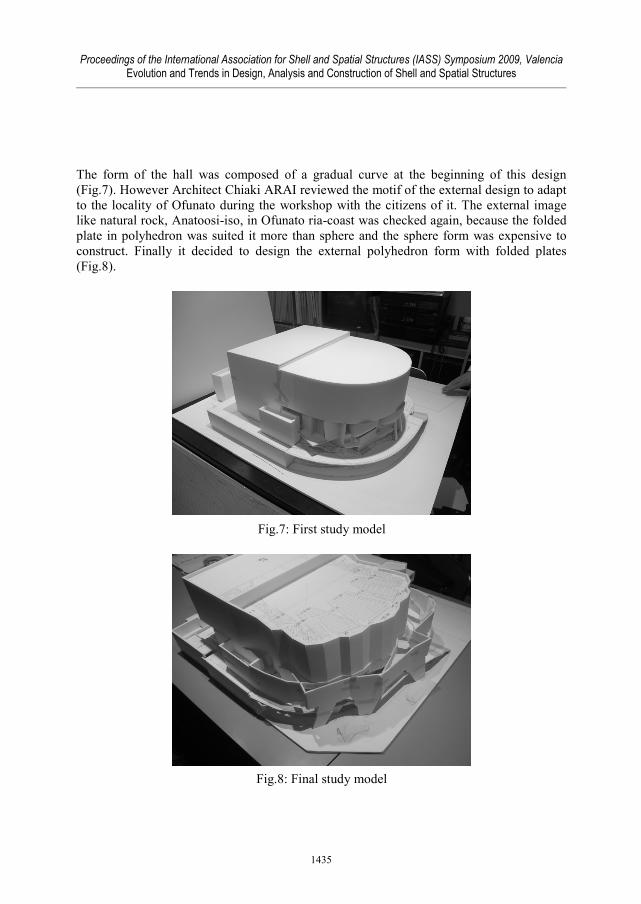
The form of the hall was composed of a gradual curve at the beginning of this design(Fig.7). However Architect Chiaki ARAI reviewed the motif of the external design to adaptto the locality of Ofunato during the workshop with the citizens of it. The external imagelike natural rock, Anatoosi-iso, in Ofunato ria-coast was checked again, because the foldedplate in polyhedron was suited it more than sphere and the sphere form was expensive toconstruct. Finally it decided to design the external polyhedron form with folded plates(Fig.8).
Fig.7: First study model
Fig.8: Final study model
1435

Proceedings of the International Association for Shell and Spatial Structures (IASS) Symposium 2009, ValenciaEvolution and Trends in Design, Analysis and Construction of Shell and Spatial Structures
3. Study of structure3.1. Basic ConceptRias-Hall is the complex facility consisted of three zones, which are hall zone, library zoneand service zone. In hall zone there are the hall which composed of 1100 audience seats andthe stage for musical concert (Fig.9), and foyer and restaurant around it (Fig.10&11). Thereare dressing rooms and equipment rooms in service zone. The basic concept of structuraldesign is the composition of structural elements not to disturb each others and each space.Those points to create the structural elements for each demand performances are as follows:
1. In hall zone each space are arranged to fold. Especially the audience seats are put outto foyer and restaurant side, because the amount of the upper audience seats isrequired in advance. Therefore the bottom of the audience seats appears as an innerskin inclined to outside when it is looked up from foyer side. Also it is folded plateof polyhedron according to arrangement of the upper audience seats divided threeparts. The outer skin on out side of foyer consists of folded plates. It is possible toget comfortable space not to disturb other one, because the inner skin and outer oneare composed as structure. At the same time, it is important to study how to bear thisupper audience seats.
Fig.9: Audience seats of the hall
Fig.10: Foyer of the hall zone
Fig.11: Reataurant of the hall zone
1436

Proceedings of the International Association for Shell and Spatial Structures (IASS) Symposium 2009, ValenciaEvolution and Trends in Design, Analysis and Construction of Shell and Spatial Structures
2. The demand performance of service zone is to create the reasonable, practical andsimple frame. Then the form is hexahedron basically and the structure is flat plate ofit (Fig.12).
3. Library has the wall-girders connected with upper walls on same plane to get largecontinuous space with unifying reference room (Fig.13).
Fig.12: Service zone outside view
Fig.13: Library reference room
1437

Proceedings of the International Association for Shell and Spatial Structures (IASS) Symposium 2009, ValenciaEvolution and Trends in Design, Analysis and Construction of Shell and Spatial Structures
3.2. Study of Structural frame~From “how to bear the audience seats”to “how to bear with audience seats~
At first the audience seats on the second floor could be formed three independent bowlswith two columns in each one (Fig.14). However, the bearing system was consideredagain because the columns were interfered with the foyer and that form didn’t match theorganic image like ria-coastline. Chiaki ARAI, Architect, had an image for the internalseats like the forward part of a ship.It seems that there were some rules to design the structure of the ship though it can becomplicated seemingly. Is it really possible to support the upper structure of the hall bythe audience seats? In other words, the structure can be that the audience seats unify withthe roof of the hall.Then this structure was considered the semi-monocoque composed of frames and platesby regarding it as a body of ship, especially hall roof as upper deck and folded platewalls as outside plates (Fig.15).Generally it is necessary to design as Cantilever beam the radial frames in the pit underthe audience seats for air condition. Here when these radial frames were extended untiloutside of the hall and support the upper structure of the hall, it seemed that the innerload on the frames counterbalances the outer one. If these radial frames worked like therib of the ship, it could be supported the upper structure. The enough thickness andheight were designed not only for normal force but also for bending and shear stress,because the ducts penetrated through these frames.These rib frames were supported to connect with folded plate walls which were designedlike concentric circle as the wall between hall and foyer. Therefore the folded plate wallsworked as the keel-girders for radial frames. Automatically it could be stabilized by twopoints where each frame intersected with the folded plate walls. These folded plate wallswere the element to resist against the force with high rigidity like an arch rather than abeam because they had some bulged opening. They transfered the load of the normalforce to the foundation.
3.3. Flying-buttress on the foyerOn the one hand, the traditional flying buttress is transfered the thrust on the vault roof forthe long-term load. On the other hand, these flying butresses (Fig.16), which wereconnected between the inner skin and the outer skin on the upper side of foyer, not onlywas transfered parts of the stress to outside by the weight hall roof, but also was securedunifying between inner and outer on the earthquake particulary. Therefore these had the flatV-form sections, because these were needed not only the rigidity of the normal stress, butalso the horizontal one for bending shear
1438

Proceedings of the International Association for Shell and Spatial Structures (IASS) Symposium 2009, ValenciaEvolution and Trends in Design, Analysis and Construction of Shell and Spatial Structures
Fig.16: Flying buttress on the foyer
Fig.15: Structural Diagram of Rias-hall
Fig.14: Fisrt structural sketch
1439

Proceedings of the International Association for Shell and Spatial Structures (IASS) Symposium 2009, ValenciaEvolution and Trends in Design, Analysis and Construction of Shell and Spatial Structures
3.4. Library –continuous reference roomThe wall-girder, whose height is the one of a layer, was continued on the same plane to theone of studio and multiple space on the upper floor, because it can be got large continuousspace with unifying reference room. In the other words, the continuous wall-girder weredesigned from lower floor to upper floor. Threrfore it can be designed the minimumamounts of columns in reference room by wall girder.
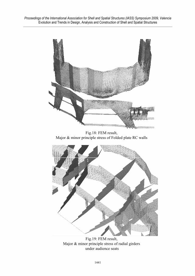
3.5. To solve complicated form, to design flat thick wallThe method of structural design was based on Japanese seismic codes and AIJ standard[1],[2],therefore we conducted two structural analysis. One is a FEM liner analysis and another is abeam element model of non-linear analysis.1. FEM linear analysis
The analysis of this complicated form was executed with the 3D model using FEManalysis programm (MSC/Nastran) (Fig.18&19).The more the plan and section were changed influenced by the workshop with citizens,the more the study model, scale 1:50, was transformed. Therefore it proceeded in eachsections at the same time that the verification of the analysis model made by this studymodel was reflected to architectural design and service design.
2. Non-linear analysisBesides FEM linear analysis, the pushover analysis with simplified flame model wasmade. In this hall, the ultimate capacity which it was necessary was set when the valueof the ductility reduction factor (Ds) of Japanese seismic codes was 0.55.The ultimate capacity was set when the beams between surface elements were brokenwith shear stress partially. However it was confirmed that the one at this time exceededthe demand capacity of Japanese seismic codes (Fig.20).
Fig.17: Library,continuous reference room
1440
Proceedings of the International Association for Shell and Spatial Structures (IASS) Symposium 2009, ValenciaEvolution and Trends in Design, Analysis and Construction of Shell and Spatial Structures
Fig.18: FEM result,Major & minor principle stress of Folded plate RC walls
Fig.19: FEM result,Major & minor principle stress of radial girders
under audience seats
1441

Proceedings of the International Association for Shell and Spatial Structures (IASS) Symposium 2009, ValenciaEvolution and Trends in Design, Analysis and Construction of Shell and Spatial Structures
4. ConstructionRias-Hall was planned with cast-in-place concrete, which is highly-popularizedconstruction method in Japan. And the skeleton was constructed by local rebar workers andformworkers (Fig.22~23).To get untroubled layout of reinforcement and to enable enough concrete fill, Rias-hall wasconstructed of uniform 30~40cm thickness walls.Especially, under construction, temporary supports under the hall and library, which were at1st floor level, were kept by the time the strength of the upper concrete reached to thedesigned value (Fig.21).
Fig.21 Temporary supportsunder the hall, 1st floor level
X direction Y direction
Fig.20 Ultimate capacity of Rias-hall(Ds factor= 0.55)
1442

Proceedings of the International Association for Shell and Spatial Structures (IASS) Symposium 2009, ValenciaEvolution and Trends in Design, Analysis and Construction of Shell and Spatial Structures
AcknowledgementWe would like to thank for Architect Chiaki ARAI and his stuff, Toda corporation, TakumiKensetsu and Ofunato citizens. Also we thank a lot for our family.
References[1] Architectual Institute of Japan, Standard for Structural Calculation of Reinforced
Concrete Structures -Based on Allowable Stress Concept- , 1999[2] Architectual Institute of Japan, Ultimate Strength and Deformation Capacity
Buildings in Seismic Design , 1990
Fig.23 Reinforcement of the audience seats and girders
Fig.22 Formwork of the audience seat and radial girders
1443