Structural design including disaster (wind & cyclone land slide_eq_ resistant design of structures
163
‘Structural Design including Disaster Resistant Design of Structures’
-
Upload
rajesh-jain -
Category
Engineering
-
view
21 -
download
2
Transcript of Structural design including disaster (wind & cyclone land slide_eq_ resistant design of structures

‘Structural Design including Disaster Resistant Design of Structures’

• Part 6 Structural Design
Structural Safety
– 7 Sections– 438 pages – almost half the NBC

Part 6 Structural Design
• Section 1 Loads, Forces and Effects
• Section 2 Soils and Foundations
• Section 3 Timber and Bamboo 3A Timber
3B Bamboo
• Section 4 Masonry

Part 6 Structural Design contd…
• Section 5 Concrete 5A Plain and Reinforced Concrete
5B Prestressed Concrete
• Section 6 Steel
• Section 7 Prefabrication, Systems Buildings and Mixed/Composite Construction
7A Pre-fabricated concrete7B Systems Buildings and
Mixed/Composite Construction
IS 875 Code
• IS 875 Code of practice for design loads (other than earthquake) for buildings and structures;
Part 2 : 1987 Imposed loads (second revision)
Part 3 : 1988 Wind loads (second revision)
Part 4 : 1987 Snow loads (second revision)
Part 5 : Special loads and load combination (second revision)

IS 875 Code
• Also refer to SP 64 (S&T) :2001 ‘ Explanatory Handbook on Indian Standard code of practice for design loads (other than earthquake) for buildings and structures : Part 3 Wind Loads
Section 1 Loads, Forces and Effects
• Revised Standard IS 1893 (Part 1) – 2002 ‘Criteria for Earthquake resistant design of structures: Part 1 General provisions and Buildings (fifth revision)’

Imposed loads
• Residential Buildings• Educational buildings• Institutional Buildings• Assembly Buildings• Business and Office Buildings• Mercantile buildings• Industrial Buildings• Storage Buildings

Imposed loads
• Label indicating Designed Imposed Loading to be displayed at a conspicuous place.
– Distributed Load kN/m2– Concentrated Load kN

Wind Load
• Equivalent static load for steady wind load is ok for short and heavy structures
• Gust factor method considering drag on structures for flexible structures
• In case of tall structures with unsymmetrical geometry designs are to be checked for torsional effects

Wind Load
• Depends on
– risk level– terrain roughness, height and size of structure– local topography

Wind Load
• Basic wind speed Map( based on 50 year return period from code


Wind &
Cyclone
Map
of India

TOO SMALL FOR
LIGHT WEIGHT
BUILDING, PULLED
COMPLETELY OUT OF
THE GROUND
FOUNDATIONS

Dramatic & Total Destruction Of Large, Steel, Portal Frame Building
STEEL FRAMES

LOSS OF CORRUGATED, METAL, ROOF SHEETS
ROOF SHEETING
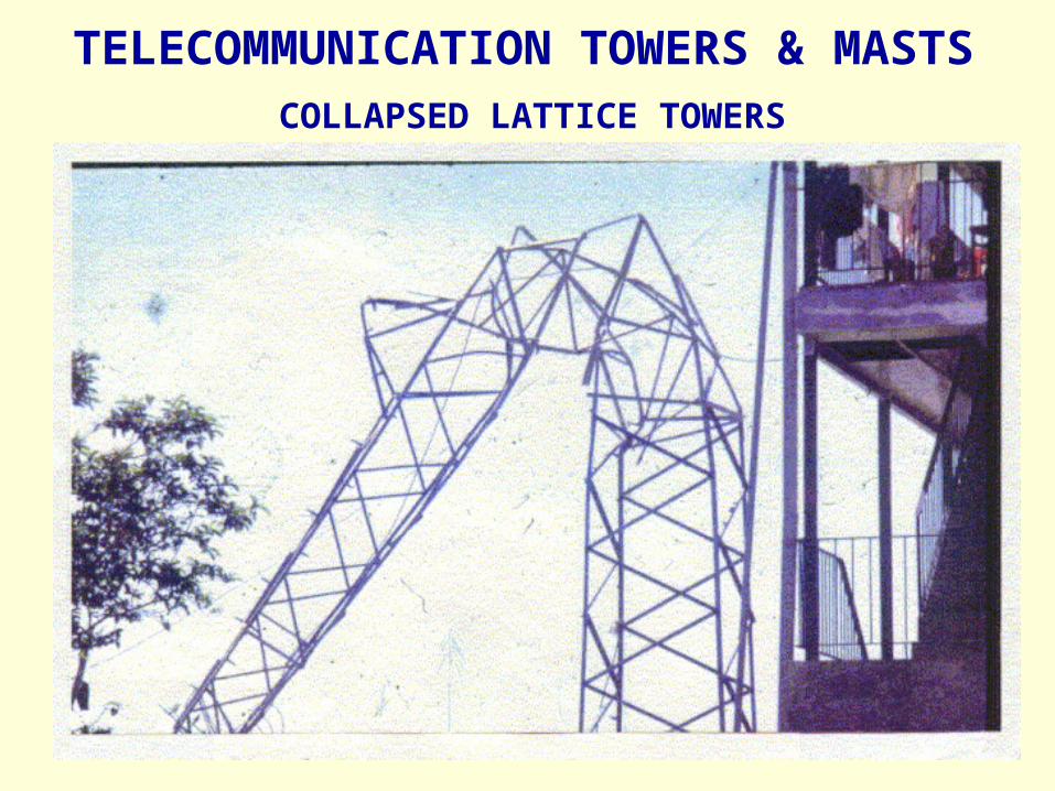
COLLAPSED LATTICE TOWERS
TELECOMMUNICATION TOWERS & MASTS
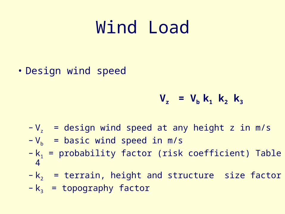
Wind Load
• Design wind speed
Vz = Vb k1 k2 k3
– Vz = design wind speed at any height z in m/s– Vb = basic wind speed in m/s– k1 = probability factor (risk coefficient) Table 4– k2 = terrain, height and structure size factor – k3 = topography factor

Wind Load
• Design wind pressure
pz = 0.6 Vz2

Wind Load
• Pressure Coefficients
Cp code gives tables for various types and shapes of buildings

Seismic load
• IS 1893 : 2002 ‘


Lack of shear connection between floors and the
elevator shaft
5 storey R.C., collapse of open plinth, water tank at top dislocated
(Bhuj)

Identical 4 storeyed R.C. buildings (Amdavad) two
out of four collapsed
Collapse of R.C. frame railway station
building at Vondh

Soft ground storey collapse (Amdavad)
Pancake collapse of a R.C. Building
(Gandhidham)
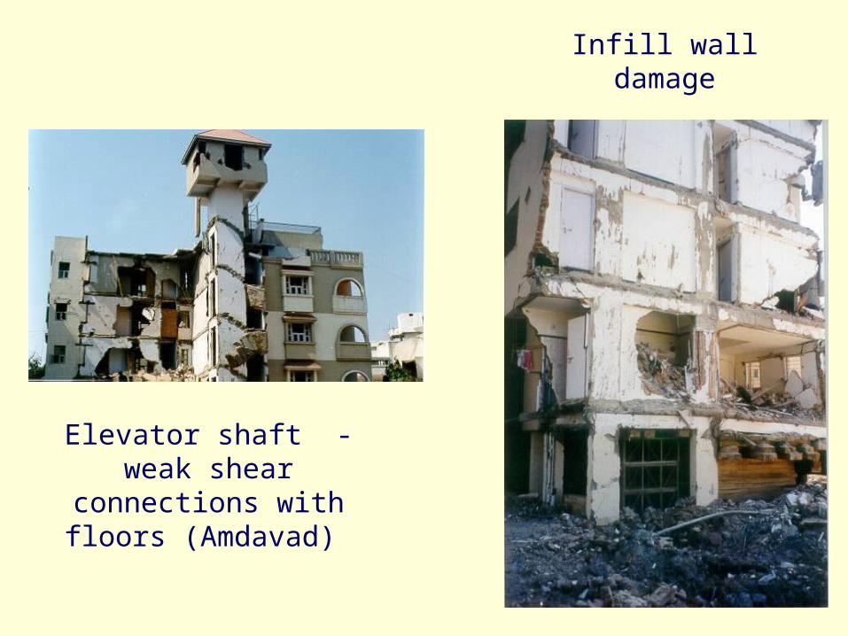
Elevator shaft - weak shear connections with
floors (Amdavad)
Infill wall damage

BIS Standards
• IS 1893-2002 : Criteria for earthquake
resistant design of structures
• IS4326-1993 : Earthquake Resistant Design
and construction for buildings – code of
practice (second revision)
• IS 13920-1993 : Ductile detailing of RC
structures subjected to seismic forces –
code of practice
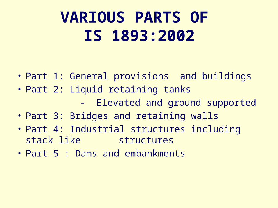
VARIOUS PARTS OF IS 1893:2002
• Part 1: General provisions and buildings• Part 2: Liquid retaining tanks
- Elevated and ground supported• Part 3: Bridges and retaining walls• Part 4: Industrial structures including stack like
structures• Part 5 : Dams and embankments

Important Modifications
• Design Basis Earthquake (DBE)
E/Q that can reasonably be expected to occur once during the design life of the structure
• Maximum Considered Earthquake (MCE)
The most severe earthquake effects considered by this standard

Assumptions
• Generally designed for earthquake coming from one direction at a time
• Resonance will not occur
• Earthquake will not occur with extreme
wind

Performance criteria
• Moderate Earthquake– Without structural damage– Could occur a number of times in the life span– Code based design seismic coefficients
• Large earthquake– Without collapse– May occur once in the life of the structure– Not catered by the codal design seismic co-
efficient– Additional resistant by incorporating details for
ductility
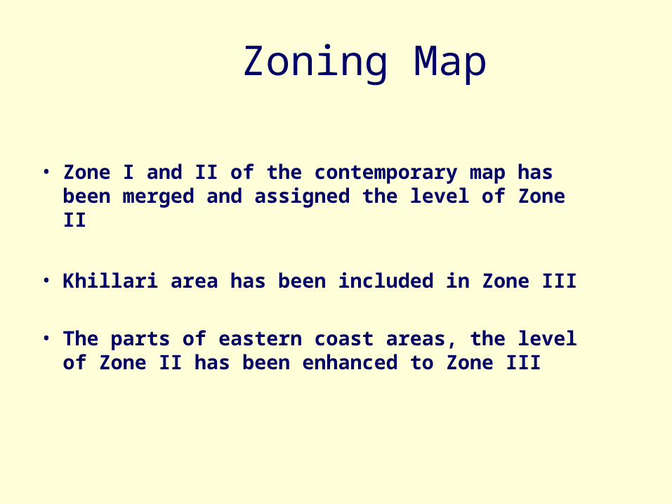
Zoning Map
• Zone I and II of the contemporary map has been merged and assigned the level of Zone II
• Khillari area has been included in Zone III
• The parts of eastern coast areas, the level of Zone II has been enhanced to Zone III


Seismic Zone Factors
• Maximum Considered Earthquake(MCE)– The most severe earthquake effects considered by
this standard
• Zone Factor (Z)– It is a factor to obtain the design spectrum depending
on the perceived maximum seismic risk characterized by MCE in the zone in which the structure is located.
– The basic zone factors included in this standard are reasonable estimate of effective peak ground acceleration
Seismic Zone II III IV V
Factor 0.1 0.16 0.24 0.36

DESIGN HORIZONTAL LOAD
• When lateral resisting elements are orthogonal, consider e/q load in one direction at a time.
• When non-orthogonal– Combine full load in one direction with
30% of load in other direction EL in load combination replaced by
ELx±0.3ELy or 0.3ELx±ELy

Response reduction factor (R)
• It is the factor by which the actual base shear force, shall be reduced to obtain the design lateral force.– Actual base shear force - that would be generated if the
structure were to remain elastic during its response to the Design Basis Earthquake (DBE) shaking.
– The values of ‘R’ depend upon seismic damage performance of the structure, i.e. ductile/brittle.
• Design Basis Earthquake (DBE)– It is the earthquake which can reasonably be expected to
occur at least once during the design life of the structure.– Z / 2

Response Reduction Factor(R)
Ordinary RC moment-resisting frame(OMRF) 3.0Special RC moment-resisting frame(SMRF) 5.0
Load bearing masonry wall buildings
a) Un-reinforced 1.5b) Reinforced with horizontal RC bands 2.5c) Reinforced with horizontal RC bands and vertical
bars at corners of rooms and jambs of openings 3.0Ordinary reinforced concrete shear walls 3.0Ductile shear walls 4.0Ordinary shear wall with OMRF 3.0Ordinary shear wall with SMRF 4.0Ductile shear wall with OMRF 4.5Ductile shear wall with SMRF 5.0
Lateral Load Resisting System R

Design Lateral Force Revised
• Design Seismic Base Shear (VB ) (Lower Bound)
VB = Ah W
Where,
Ah = Design horizontal acceleration spectrum using the
approximate fundamental natural period Ta (Clause 7.6) in the considered direction of vibration; and
W = Seismic weight of the building
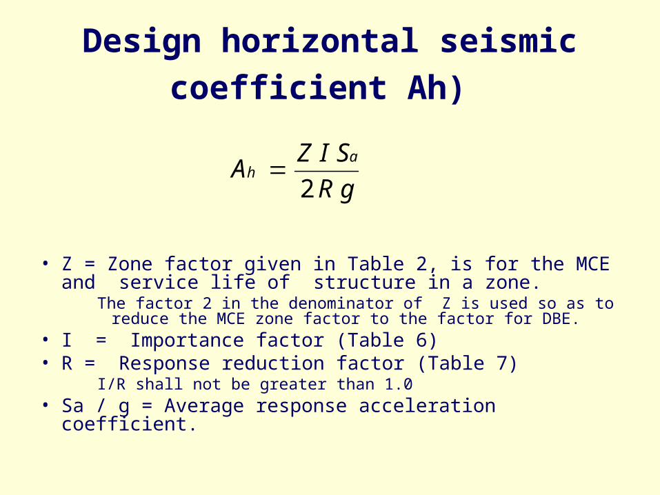
Design horizontal seismic coefficient Ah)
• Z = Zone factor given in Table 2, is for the MCE and service life of structure in a zone.
The factor 2 in the denominator of Z is used so as to reduce the MCE zone factor to the factor for DBE.
• I = Importance factor (Table 6)• R = Response reduction factor (Table 7)
I/R shall not be greater than 1.0• Sa / g = Average response acceleration coefficient.
gR
SIZA
ah
2

Response Spectra
1. 0
3.0
2.0
1.0 2.0 3.0 4.0
Type III (Soft soil)
Type II (Medium soil)
Type I (Rock, or Hard soil)
Period
Sp
e ctr
al A
c ce l
erat
ion
Coe
ffic
i en
t (S
a /g
)

Fundamental Natural PeriodRC frame building
• Moment-resisting frame building without brick infill panels
Ta = 0.075 h0.75
[Old version, Ta = 0.1N(No. of storey) , No mention about the brick infill panel]
• Moment-resisting frame buildings with brick infill panel
where,
h = Height of building and
d = Base dimension of the building at the plinth level, in m, along with considered direction of the lateral force.
dh
aT 09.0
Attributes to perform well in a earthquake
• Simple and regular configuration
• Adequate lateral strength
• Adequate stiffness
• Adequate ductility

Regular and Irregular Configuration
• Buildings having simple regular configuration suffer less damage than buildings with irregular configuration.
• Regular Configuration– Simple regular geometry– Uniformly distributed mass and stiffness in plan and
elevation
• Irregular configuration– As defined in Table 4 and 5 of the code

Plan and Vertical Irregularities
Plan Irregularities
• Torsion Irregularity
• Re-entrant Corners
• Diaphragm Discontinuity
• Out-of-plane offsets
• Non-parallel systems

Plan Irregularities (Table 4)
• Tortional Irregularity– To be considered when floor diaphragms are rigid in
their own plan – when the maximum storey drift, computed with design
eccentricity, at one end of the structure transverse to an axis is more than 1.2 times the average of the storey drifts at the two ends of the structure. { 2 =1. 2 (1 + 2) / 2}
1 2
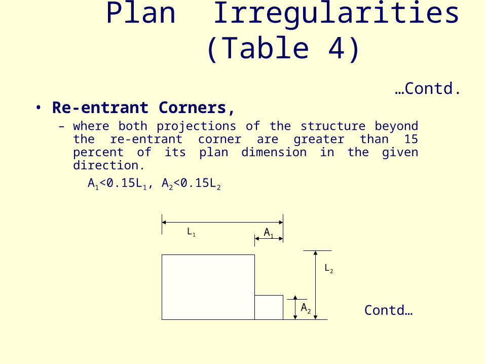
Plan Irregularities (Table 4) …Contd.
• Re-entrant Corners, – where both projections of the structure beyond the re-entrant
corner are greater than 15 percent of its plan dimension in the given direction.
A1<0.15L1, A2<0.15L2
Contd…
L1
L2
A1
A2

Plan Irregularities (Table 4) …Contd.
• Diaphragm Discontinuity
– Diaphragms with abrupt discontinuities or variations in stiffness:
• those having cut-out or open areas greater then 50 percent of the gross enclosed diaphragm area
• or changes in effective diaphragm stiffness of more than 50 percent from one storey to the next.
Contd…

Plan Irregularities (Table 4) …Contd.
• Out-of-Plan Offsets– Discontinuities in a lateral force resistance path, such as
out-of plan offsets of vertical elements.
Position of shear wall
Ground Floor Plan First Floor Plan

Plan Irregularities (Table 4) …Contd.
Non-Parallel Systems– The vertical elements resisting the lateral force are not
parallel to or symmetric about the major orthogonal axes or the lateral force resisting elements.
X
Y

Vertical Irregularities
• Stiffness irregularity – soft storey
• Mass irregularity
• Geometric irregularity
• In-plane discontinuity
• Discontinuity in capacity – weak storey
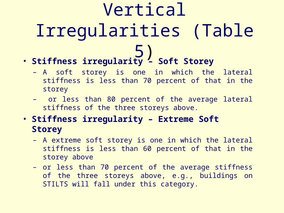
Vertical Irregularities (Table 5)
• Stiffness irregularity – Soft Storey– A soft storey is one in which the lateral stiffness is less
than 70 percent of that in the storey – or less than 80 percent of the average lateral stiffness of
the three storeys above.
• Stiffness irregularity – Extreme Soft Storey– A extreme soft storey is one in which the lateral stiffness is
less than 60 percent of that in the storey above – or less than 70 percent of the average stiffness of the three
storeys above, e.g., buildings on STILTS will fall under this category.

Vertical Irregularities (Table 5) …Contd.
• Mass Irregularity– Mass irregularity shall be considered to exist where the
seismic weight of any storey is more than 200 percent of that of its adjacent storeys.
– The irregularity need not be considered in case of roofs.
• Vertical Geometric Irregularity– Vertical geometric irregularity shall be considered to exist
where the horizontal dimension of the lateral force resisting system in any storey is more than 150 percent of that in its adjacent storey.
Contd…

Vertical Irregularities (Table 5) …Contd.
• In-Plane Discontinuity in Vertical Elements Resisting Lateral Force– A in-plane offset of the lateral force resisting
elements greater than the length of those elements.
• Discontinuity in Capacity – Weak Storey– A weak storey is one in which the storey lateral
strength is less than 80 percent of that in the storey above.
– The storey lateral strength is the total strength of all seismic force resisting elements sharing the storey shear in the considered direction.
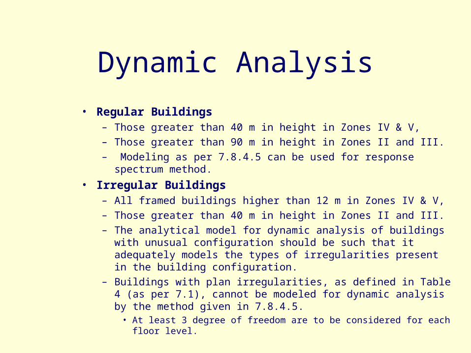
Dynamic Analysis
• Regular Buildings– Those greater than 40 m in height in Zones IV & V, – Those greater than 90 m in height in Zones II and III.– Modeling as per 7.8.4.5 can be used for response spectrum
method.
• Irregular Buildings– All framed buildings higher than 12 m in Zones IV & V, – Those greater than 40 m in height in Zones II and III. – The analytical model for dynamic analysis of buildings with
unusual configuration should be such that it adequately models the types of irregularities present in the building configuration.
– Buildings with plan irregularities, as defined in Table 4 (as per 7.1), cannot be modeled for dynamic analysis by the method given in 7.8.4.5.
• At least 3 degree of freedom are to be considered for each floor level.

Buildings with Soft Storey
*Buildings with a flexible storey,– such as the ground storey consisting of open spaces for
parking that is Stilt buildings,– special arrangements needs to be made to increase the
lateral strength and stiffness of the soft/open storey.
• Dynamic analysis of building is carried out including – the strength and stiffness effects of infill and – inelastic deformations in the members particularly, those
in the soft storey,
and the members designed accordingly. Contd….

Buildings with Soft Storey…contd.
• Alternatively, – Carrying out the earthquake analysis, neglecting the
effect of infill walls in other storeys.– The columns and beams of the soft storey are to be
designed for 2.5 times the storey shears and moments calculated under seismic loads specified in the other relevant clauses; or
– Besides the columns designed and detailed for the calculated storey shears and moments, shear walls placed symmetrically in both directions of the building as feasible; to be designed exclusively for 1.5 times the lateral storey shear force calculated as before.

Need for ductility
• Earthquake resistant design – costs money• Cost increases geometrically for no damage
design• Codes adopts lower coefficient
– reduction factor
• Provisions for durability for once in life earthquake
• Design criteria is no-collapse design• IS-13920 – 1993 detailing for ductility

Roof-top DisplacementRoof-top Displacement
V/W
V
/W
(Ac
cel
era
tio
n)
(Ac
cel
era
tio
n)
Low-Strength; Low-Stiffness; BrittleLow-Strength; Low-Stiffness; Brittle
Moderate Strength and Stiffness; DuctileModerate Strength and Stiffness; Ductile
High-Strength; High-Stiffness; BrittleHigh-Strength; High-Stiffness; Brittle

Principles of ductility
• Avoid shear failure• Avoid compression failure• Ensure continuity• Confine the critical areas where hinge can form.

Snow load
• s = μ s0
s = design snow load in N/m2
μ = shape coefficient
s0 = Ground snow load
Special Loads
• Temperature Effects
• Hydrostatic & soil Pressure
• Fatigue
• Structural Safety during construction
• Accidental loads
• Vibrations

Load Combinations
• Various loads are to be combined to evaluate the most unfavourable effect
• Simultaneous occurrence of maximum values of wind, earthquake, imposed and snow load is not likely
Multi – Hazard Risk
• Earthquake• Cyclones• Windstorm• Floods• Landslides• Liquefaction of soils• Extreme winds• Cloud bursts• Failure of slopes

DISASTER MANAGEMENT CYCLE
Emergency Response
Post-disaster: recovery
Preparedness
Prevention/ Mitigation
Reconstruction
Rehabilitation
Response/ Relief
Pre-disaster: risk reduction
Disaster
Emergency Response
Post-disaster: recovery
Preparedness
Prevention/ Mitigation
Reconstruction
Rehabilitation
Response/ Relief
Pre-disaster: risk reduction
Disaster
Multi – Hazard Risk
• Code gives criteria for identifying the multi-hazard districts and a list of such districts is at Ann: M

Vulnerability Atlas of India, 1987
• Seismic hazard map
• Cyclone and wind map
• Flood prone area map
• Housing stock vulnerability table

Vulnerability Atlas of India, 1987
• Landslide Hazard Zonation Atlas, 2003
BMTPC
Hazard Maps
The earthquake , wind storm and flood hazard maps are drawn for each state and Union Territory separately in which various district boundaries are clearly shown for easy identification of the hazard prone areas.

The Vulnerability Atlas of India
The Vulnerability Atlas of India has been structured to serve as a tool towards natural disaster prevention , preparedness and mitigation for housing and related infrastructure at local as well as national levels.

Hazard Maps
The earthquake , wind storm and flood hazard maps are drawn for each state and Union Territory separately in which various district boundaries are clearly shown for easy identification of the hazard prone areas.

Flood Hazard
Map of
India


LANDSLIDE HAZARD
MAP OF
INDIA


EARTHQUAKE HAZARD MAP OF GUJARAT

FLOOD HAZARD MAP OF GUJARAT

WIND & CYCLONE HAZARD MAP OF GUJARAT

TABLE 1 – BUILDING TYPES IN FIVE DISTRICTS OF GUJARAT
Wall Type No. of Houses and percentage of Total in DistrictKachchh %
Jamnagar %
Banaskantha (incl. Patan) %
Rajkot
%
Surendranagar
%
Category A 276,390 70.72 215,135 52.04 268,790 54.90 295,005 46.81 281,475 85.04
Category B 56,995 14.58 183,050 44.28 202,185 41.29 310,925 49.34 43,705 13.20
Category C 42,135 10.78 9,980 2.41 6,705 1.37 15,15 2.46 2,870 0.87
Category X 15,290 3.91 5,210 1.26 11,955 2.44 8,760 1.39 2,9 0.89
Total 390,810 100 413,375 100 489,635 100 630,205 100 330,995 100
Source: Vulnerability Atlas of India, 1997Category A - Building in field-stone, rural structures, unburnt brick houses, clay houses
Category B - Ordinary brick buildings; buildings of the large block and prefabricated type,
half-timbered structures, buildings in natural hewn stone
Category C - Reinforced building, well built wooden structures
Category X - Other types not covered in A,B,C. as of biomass, metal sheets etc.
These are generally light.

GUJARAT – EARTHQUAKE DAMAGE TO BUILDINGS
(100 YEARS RETURN PERIOD) (Number of Buildings)

ESTIMATED PROBABLE MAXIMUM SURGE AT MEAN SEA LEVEL
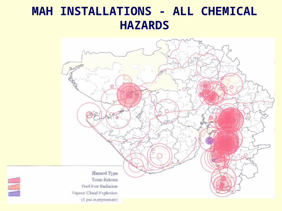
MAH INSTALLATIONS - ALL CHEMICAL HAZARDS

Section 2 Soils and Foundations
• 1080: 1985 Design and construction of shallow foundations in soils ( other than raft, ring and shell) (second revision)
• 1904: 1986 Design and construction foundations in soils : General requirements (third revision)

Section 2 Soils and Foundations contd….
• 2911 (part 1/sec 1): 1979 Design and construction of pile foundations: Part 1 Driven cast in situ concrete piles)
• 2911 (part 1/section 2): 1979 Bored cast in situ concrete piles
• 2911 (Part 1/section 3): 1979 Driven precast concrete piles
• 2911 (Part 1/section 4): 1984 Bored precast concrete piles
• 2911 Part 3): 1980 Under-reamed piles (first revision

Section 2 Soils and Foundations contd
• 2950(Part 1): 1981 Raft foundations
• 9456: 1980 Conical hyperbolic paraboloidal types of shell
foundations

Section 2 Soils and Foundations contd
• Site Investigations• Shallow foundations• Allowable bearing Pressure• Safe bearing capacity based on
shear strength• Based on allowable
settlement• Depth of foundations• On soils min 500 mm

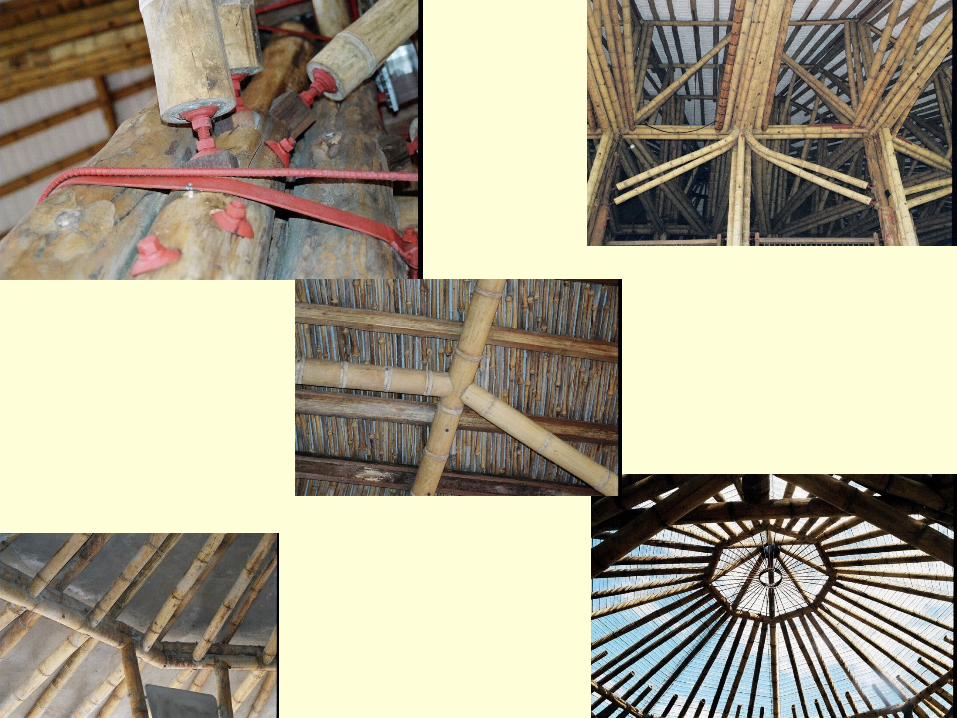
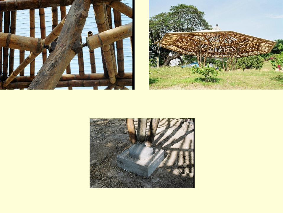
Section 3 Timber and Bamboo
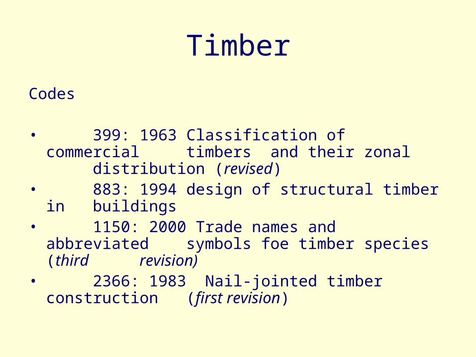
Timber
Codes
• 399: 1963 Classification of commercial timbers and their zonal distribution (revised)
• 883: 1994 design of structural timber in buildings
• 1150: 2000 Trade names and abbreviated symbols foe timber species (third revision)
• 2366: 1983 Nail-jointed timber construction (first revision)

Timber
• 4891: 1988 specification for preferred cut sizes of structural timber (first revision)
• 4983: 1968 design and construction of nailed laminated timber beams
• 11096: 1984 design and construction of bolt- jointed timber construction
• 14616: 1999 specification for laminated veneer lumber

Bamboo
Codes
• 6874: 1973 Method of test for round bamboo
• 8242: 1976 Method of test for split bamboo
• 9096: 1979 Preservation of bamboo for structural purposes
• 13958: 1994 specification for bamboo mat for general purposes


Masonry
Codes• 1905: 1987 Structural use of
unreinforced masonry (third revision)
• 4326: 1993 Earthquake resistant design and construction of buildings
• Sp 20: 1991 Handbook on masonry design and construction (first
revision)

Masonry
Changes• Special consideration for earthquakes brought
in line with IS 4326• New clause on guidelines for improving
earthquake resistance of low strength masonry buildings added
• Reference to design and of reinforced brick concrete floors and roofs has been included
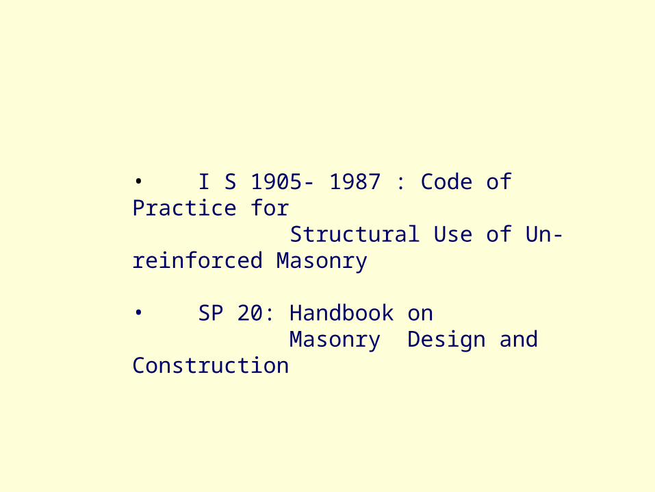
Basic Codes
• I S 1905- 1987 : Code of Practice for Structural Use of Un-reinforced Masonry
• SP 20: Handbook on Masonry Design and Construction

IS 1905 Cl. 0.6
Assumes that :
Design is carried out by qualified Engineer
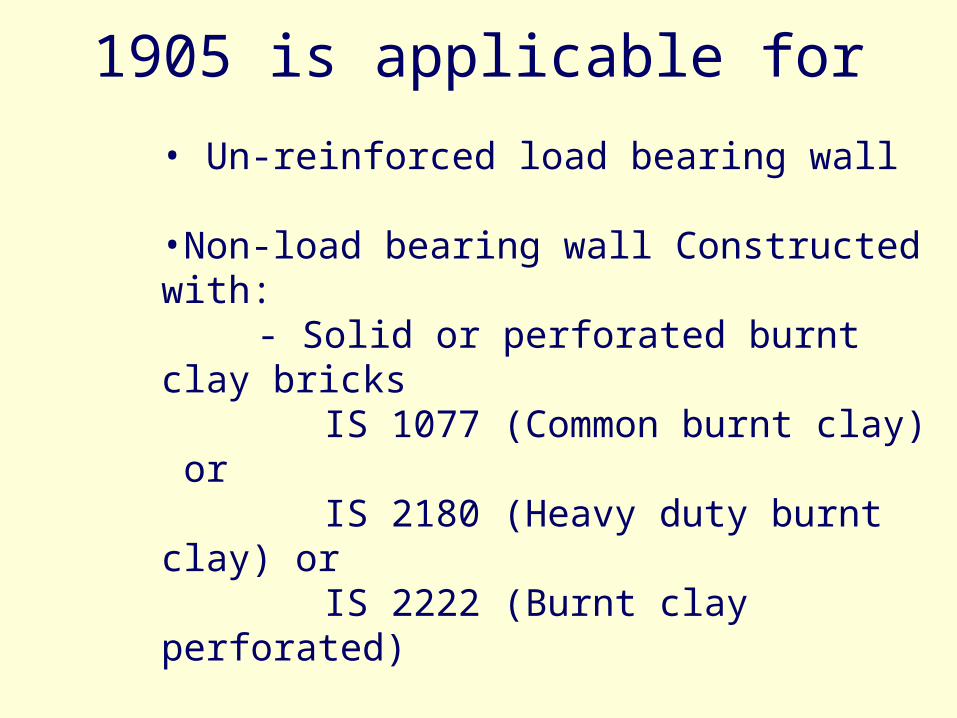
1905 is applicable for
• Un-reinforced load bearing wall
•Non-load bearing wall Constructed with: - Solid or perforated burnt clay bricks IS 1077 (Common burnt clay) or IS 2180 (Heavy duty burnt clay) or IS 2222 (Burnt clay perforated)
- Sand lime bricks IS 4139-1976
- Stones IS 3316(Structural granite) or IS 3620(Laterite block)
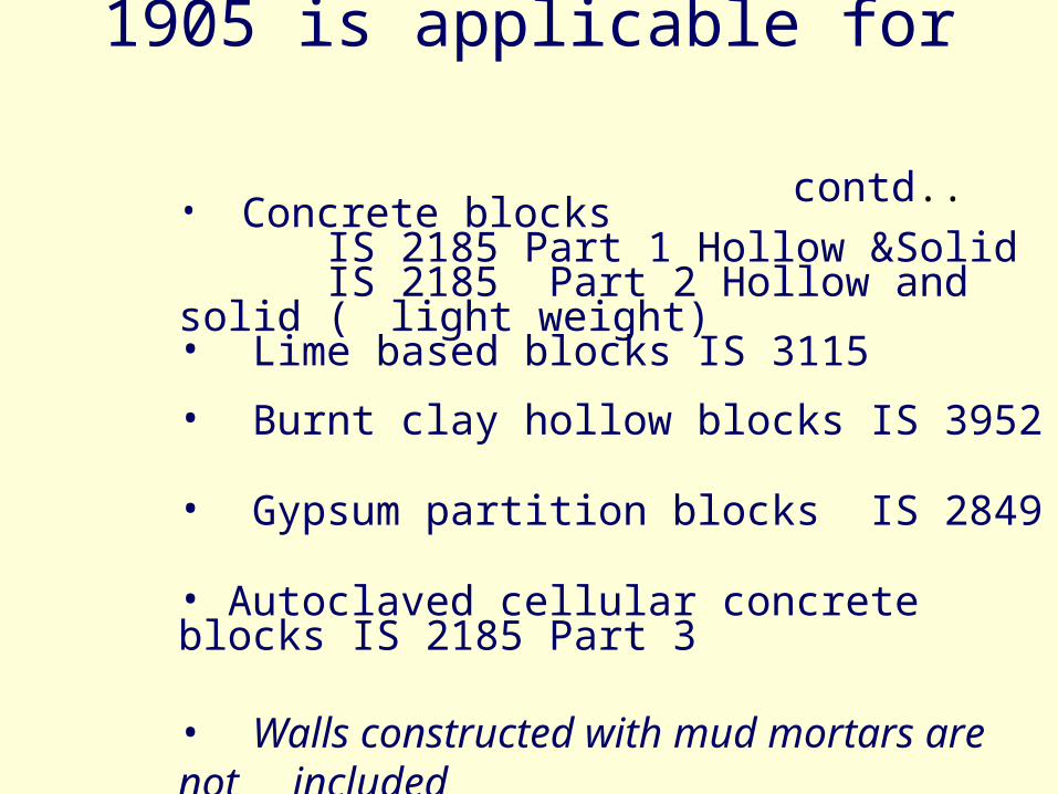
1905 is applicable for contd..
• Concrete blocks IS 2185 Part 1 Hollow &Solid IS 2185 Part 2 Hollow and solid ( light weight)
• Lime based blocks IS 3115 • Burnt clay hollow blocks IS 3952
• Gypsum partition blocks IS 2849
• Autoclaved cellular concrete blocks IS 2185 Part 3
• Walls constructed with mud mortars are not included

Planning
• Eccentricity is kept minimumAdequate stiffness of walls
Load to be uniformly distributed
• For load bearing buildings up to 4 stories, height to width ratio of buildings should not exceed 2
• For halls of length exceeding 8 m, safety and adequacy of lateral supports shall be checked by structural analysis

Mortar
Properties Lime is added to improve workability, water retention, and bonding properties Plasticised cement sand mortar
Mortar for masonry shall conform to IS 2250
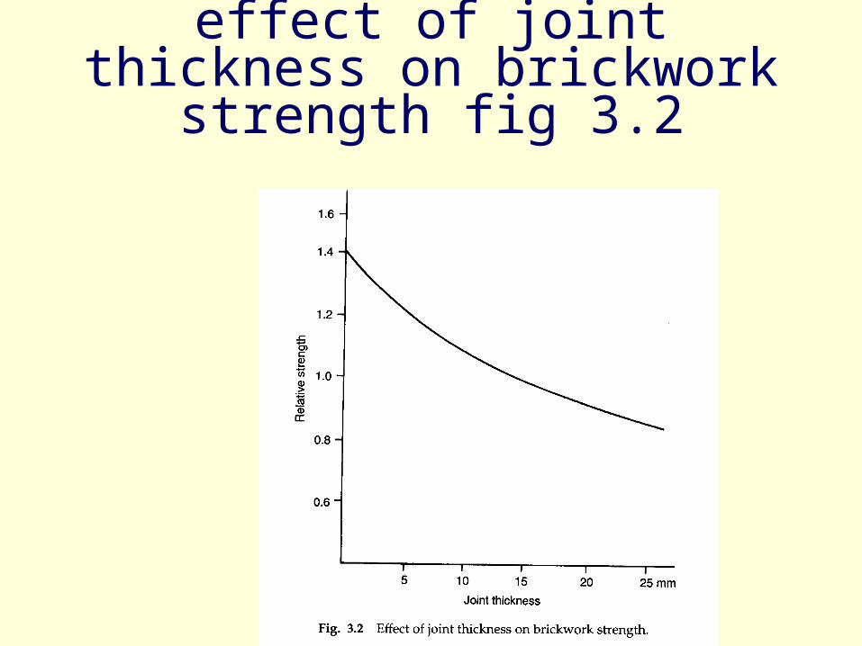
effect of joint thickness on brickwork strength fig 3.2

Method of construction
• Stone masonry IS 1597 part 1
• Rubble stone masonry
• IS part 2 Ashlars
• Brickwork masonry IS 2212
• Hollow concrete block masonry IS 2572

Method of construction contd..
• Autoclaved cellular concrete block masonry: IS 6041
• Light weight concrete block masonry:
IS 6042
• Gypsum partition blocks: IS 2849

Guidelines for Approximate Design of Non-load Bearing Wall
• Panel walls
• Curtain walls
• Partition walls
construction of RB and RBC floors and roofs
IS 10440 code of practice for construction of RB and RBC floors and roofs
IS 13828: Improving earthquake resistance of low strength masonry buildings guidelines
Earthquake Resistance

Earthquake Resistance
IS 4326: Code of Practice for Earthquake Resistant Design and Construction of Structures

Table: 2 BUILDING CATEGORIES FOR EARTHQUAKE RESISTING FEATURES (Clause 7.1.1)Building Range of h
Categories
A 0.04 to less than 0.05
B 0.05 to 0.06 (both inclusive)
C More than 0.06 and less than 0.08
D 0.06 to less than 0.12
E Equal to or more than 0.12
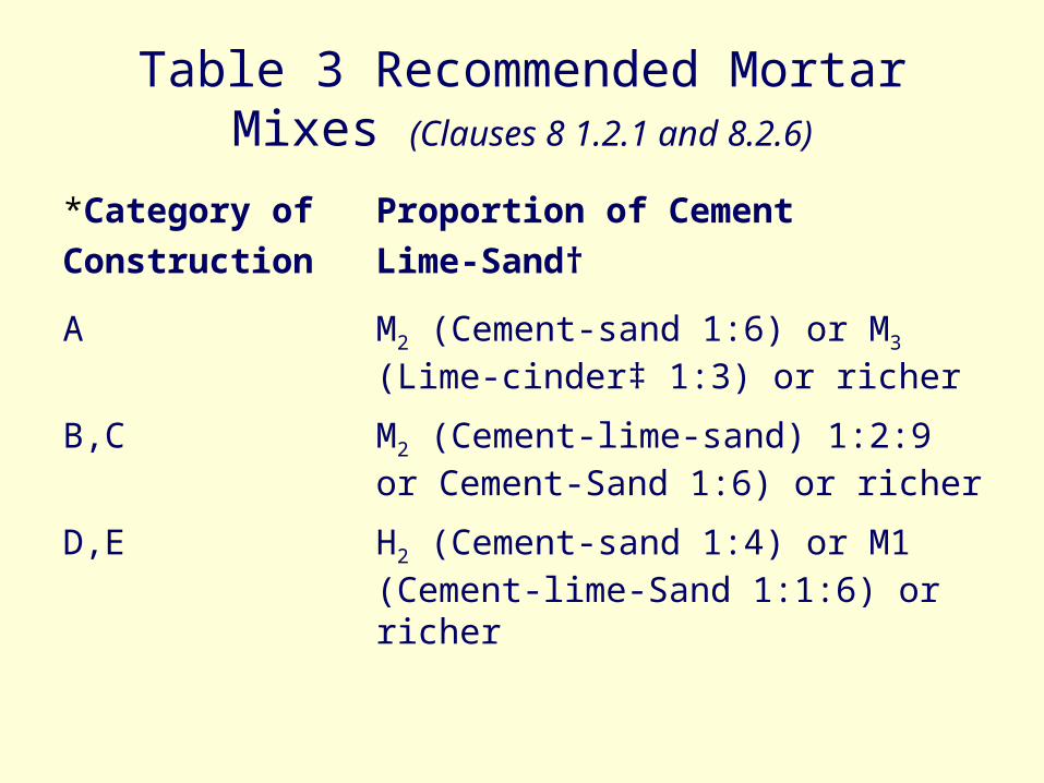
Table 3 Recommended Mortar Mixes (Clauses 8 1.2.1 and 8.2.6)
*Category of Proportion of Cement
Construction Lime-Sand†
A M2 (Cement-sand 1:6) or M3 (Lime-cinder‡ 1:3) or richer
B,C M2 (Cement-lime-sand) 1:2:9 or Cement-Sand 1:6) or richer
D,E H2 (Cement-sand 1:4) or M1 (Cement-lime-Sand 1:1:6) or richer

Table 4 SIZE AND POSITION OF OPENINGS IN BEARING WALLS (Clause 8.3.1 and Fig.7)
Sl. Position of Pening Details of Opening for Building CategoryNo.1. Distance b5 from the inside corner of A and B C D and E
outside wall, Min Zero mm 230 mm 450 mm
2. For total length of openings, the ratio(b1+b2+b3)/11 or (b6+b7)/12
shall not exceed:
a) one-storeyed building 0.60 0.55 0.50
b) two-storeyed building 0.50 0.46 0.42
c) 3 or 4-storeyed building 0.42 0.37 0.33
3. Pier width between consecutive open- 340 mm 450 mm 560 mmning b4, Min
4. Vertical distance between two open- 600 mm 600 mm 600 mmings one above the other h3, Min

Fig.7 Dimensions of Openings and Pipes for Recommendations in Table 4

Table 5 STRENTHENING ARRANGIEMENTS RECOMMENDED FOR MASONARY BUILDINGS (Rectangular Masonry Units)
Building Number of Strengthening toCategory Storeyes be Provided in all StoreyesA i) 1 to 3 a
ii) 4 a, b, cB i) 1 to 3 a,b,c,f,g
ii) 4 a,b,c,d,f,gC i) 1 and 2 a,b,c,f,g
ii) 3 and 4 a to gD i) 1 and 2 a to g
ii) 3 and 4 a to hE 1 to 3* a to h
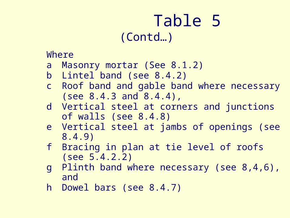
Table 5 (Contd…)
Wherea Masonry mortar (See 8.1.2)b Lintel band (see 8.4.2)c Roof band and gable band where necessary
(see 8.4.3 and 8.4.4),d Vertical steel at corners and junctions of walls (see
8.4.8)e Vertical steel at jambs of openings (see 8.4.9)f Bracing in plan at tie level of roofs (see 5.4.2.2)g Plinth band where necessary (see 8,4,6), andh Dowel bars (see 8.4.7)

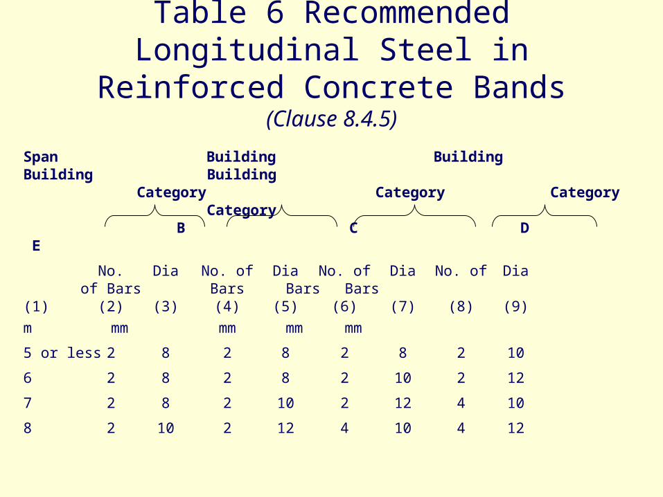
Table 6 Recommended Longitudinal Steel in Reinforced Concrete Bands
(Clause 8.4.5)
Span Building Building Building Building Category Category Category
Category B C D E
No. Dia No. of Dia No. of Dia No. of Diaof Bars Bars Bars Bars
(1) (2) (3) (4) (5) (6) (7) (8) (9)
m mm mm mm mm
5 or less 2 8 2 8 2 8 2 10
6 2 8 2 8 2 10 2 12
7 2 8 2 10 2 12 4 10
8 2 10 2 12 4 10 4 12

Cyclone Resistance
Guidelines for Improving Cyclone Resistance of Houses/Buildings


Section 5 concrete
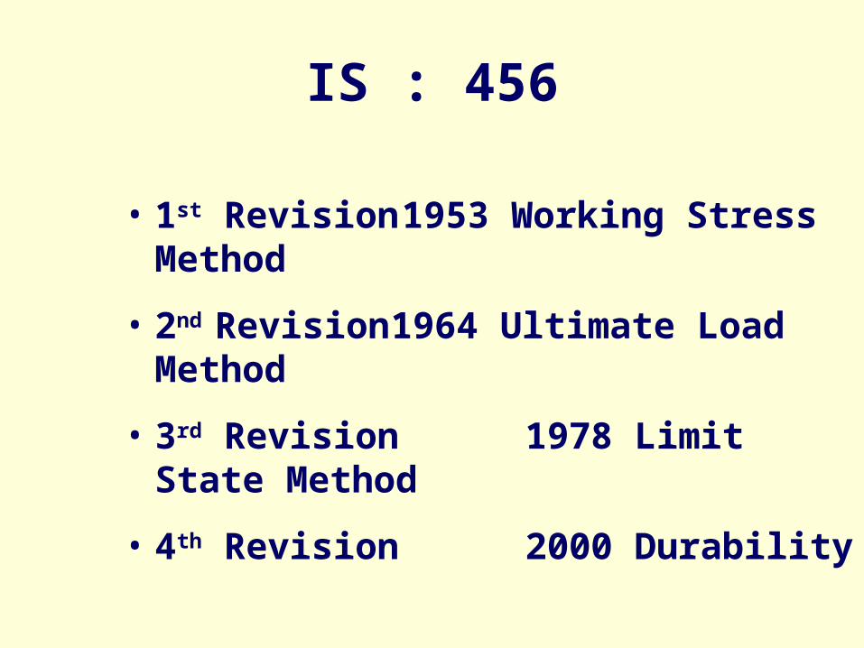
IS : 456
• 1st Revision 1953 Working Stress Method
• 2nd Revision 1964 Ultimate Load Method
• 3rd Revision 1978 Limit State Method
• 4th Revision 2000 Durability

4th Revision
Sampling and Acceptance CriteriaTypes of Cements increased.Mineral admixtures introduced Fly ash GGBS CSF Rice Husk Ash Metakaoline
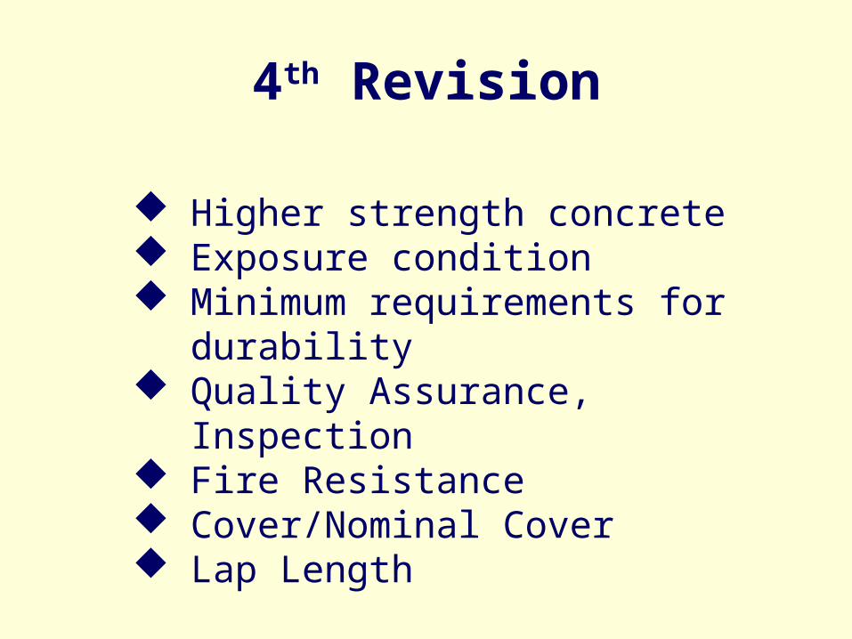
4th Revision
Higher strength concrete Exposure condition Minimum requirements for durability Quality Assurance, Inspection Fire Resistance Cover/Nominal Cover Lap Length

TYPES OF CEMENT
33 Grade Ordinary Portland cement conforming to IS 269
43 Grade ordinary Portland cement conforming to IS 8112
53 Grade ordinary Portland cement conforming to IS:12269
Rapid hardening Portland cement conforming to IS:8041
Portland slag cement conforming to IS:455

TYPES OF CEMENT
Portland pozzolana cement (fly ash based)
conforming to IS:1489 (Part 1)
Portland pozzolana cement (calcined clay
based) conforming to IS:1489 (Part 2).
Hydrophobic cement conforming to IS:8043
Low heat Portland cement conforming to
IS:12600.
Sulphate resisting Portland cement
conforming to IS:12330.

TABLE 1 PERMISSIBLE LIMIT FOR SOLIDS
(Clause 5.4) Tested as per Permissible Limit
Max.
Organic IS 3025 (Pt 18) 200 mg/1
Inorganic IS 3025 (Pt 18) 3 000 mg/1
Sulphates (as SO3) IS 3025 (Part 24) 400 mg/1
Chlorides (as C1) IS 3025 (Part 32) 2 000 mg/1 for concrete work containing embedded steel and 500 mg/1 for reinforced concrete work
Suspended matter IS 3025 (Pt 17) 2 000 mg/1

TABLE 2 : GRADES OF CONCRETE
(Clauses 6.1, 6.2.1, 9.2.1, 15.1.1 and 16.1
Group Grade
Designa-tion
Specified Characteristic Compressive Strength of 150 mm cube at 28 days in N/mm2
1 2 M 10 10 M 15 15
Ordinary Concrete
M 20 20
M 25 25 M 30 30
Standard Concrete
M 35 35
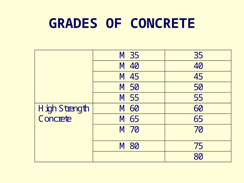
GRADES OF CONCRETE
M 35 35 M 40 40 M 45 45 M 50 50
M 55 55 M 60 60 M 65 65 M 70 70
M 80 75
High Strength Concrete
80

CONCRETE MIX
• Concrete of compressive strength less than M20
may be used for plain concrete constructions,
lean concrete, simple foundations, foundation for
masonry walls and other simple or temporary
construction.

MODULUS OF ELASTICITY
• Modulus of Elasticity of concrete
5 000 fck

HOLISTIC APPROACH TO DURABILITY
Selection of Site
Structural designs and detailing
Concrete technology
System of construction
Drainage, cover, water proofing
Inspection, maintenance & repair

FACTORS AFFECTING DURABILITY
the environment the cover to embedded steel the type and quality of constituent
material the cement content and water/cement
ratio of the concrete workmanship, to obtain full compaction
and efficient curing the shape and size of the member.
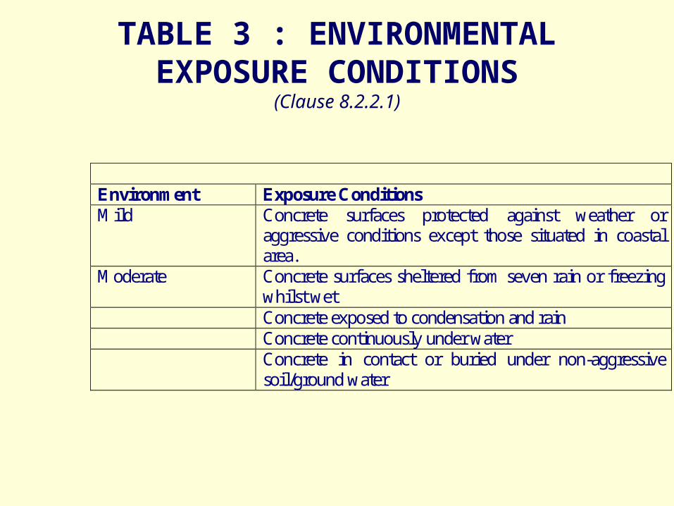
TABLE 3 : ENVIRONMENTAL EXPOSURE CONDITIONS
(Clause 8.2.2.1)
Environment Exposure Conditions Mild Concrete surfaces protected against weather or
aggressive conditions except those situated in coastal area.
Moderate Concrete surfaces sheltered from seven rain or freezing whilst wet
Concrete exposed to condensation and rain Concrete continuously under water Concrete in contact or buried under non-aggressive
soil/ground water
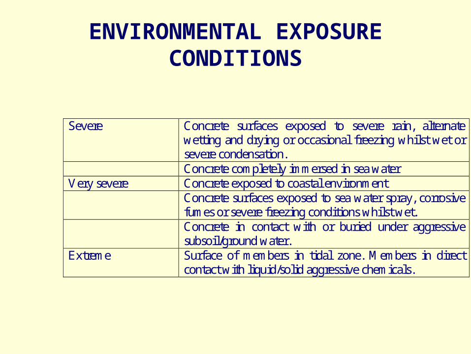
ENVIRONMENTAL EXPOSURE CONDITIONS
Severe Concrete surfaces exposed to severe rain, alternate wetting and drying or occasional freezing whilst wet or severe condensation.
Concrete completely immersed in sea water Very severe Concrete exposed to coastal environment Concrete surfaces exposed to sea water spray, corrosive
fumes or severe freezing conditions whilst wet. Concrete in contact with or buried under aggressive
subsoil/ground water. Extreme Surface of members in tidal zone. Members in direct
contact with liquid/solid aggressive chemicals.

TABLE 5 : MINIMUM CEMENT CONTENTS, MAXIMUM W/C RATION AND
MINIMUM GRADE OF CONCRETE FOR DIFFERENT EXPOSURE WITH NORMAL WEIGHT AGGREGATES OF 20 MM NOMINAL
MAXIMUM SIZE.
Exposure Plain Concrete Reinforced Concrete Minimum Grade of Concrete
Mini. Cement content Kg/m3
Max. Free w/c
Mini. Cement content Kg/m3
Max. Free w/c
Plain Concrete
Reinforced Concrete
Mild 220 0.60 300 0.55 - M20
Moderate 250 0.60 300 0.50 M15 M25
Severe 260 0.50 350 0.45 M20 M30
Very Severe 280 0.45 375 0.45 M20 M35
Extreme 300 0.40 375 0.40 M25 M40

MAXIMUM CEMENT CONTENT
• Maximum Cement Content 450 Kg/m3
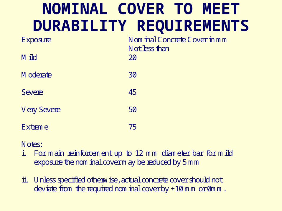
NOMINAL COVER TO MEET DURABILITY REQUIREMENTS
Exposure Nominal Concrete Cover in mm Not less than
Mild 20
Moderate 30
Severe 45
Very Severe 50
Extreme 75
Notes: i. For main reinforcement up to 12 mm diameter bar for mild
exposure the nominal cover may be reduced by 5 mm
ii. Unless specified otherwise, actual concrete cover should not deviate from the required nominal cover by +10 mm or 0mm.

DETAILING
• Corner of a section and the minimum cover to either face is less than twice the diameter of the lapped bar or where the clear distance between adjacent laps is less than 75 mm or 6 times the diameter of lapped bar, whichever is greater, the lap length should be increased by a factor of 1.4.
• Where both condition (i) and (ii) apply, the lap length should be increased by a factor of 2.0.

BATCHING
Ready mix concrete supplied by RMC plant shall be preferred.
Accuracy of equipment 2% for cement 3% for aggregate, admixture, water.

5b Prestressed concrete
• IS 1343: 1980 code of Practice for Prestressed concrete (first revision)
•
• Under revision to be incorporated when ready..
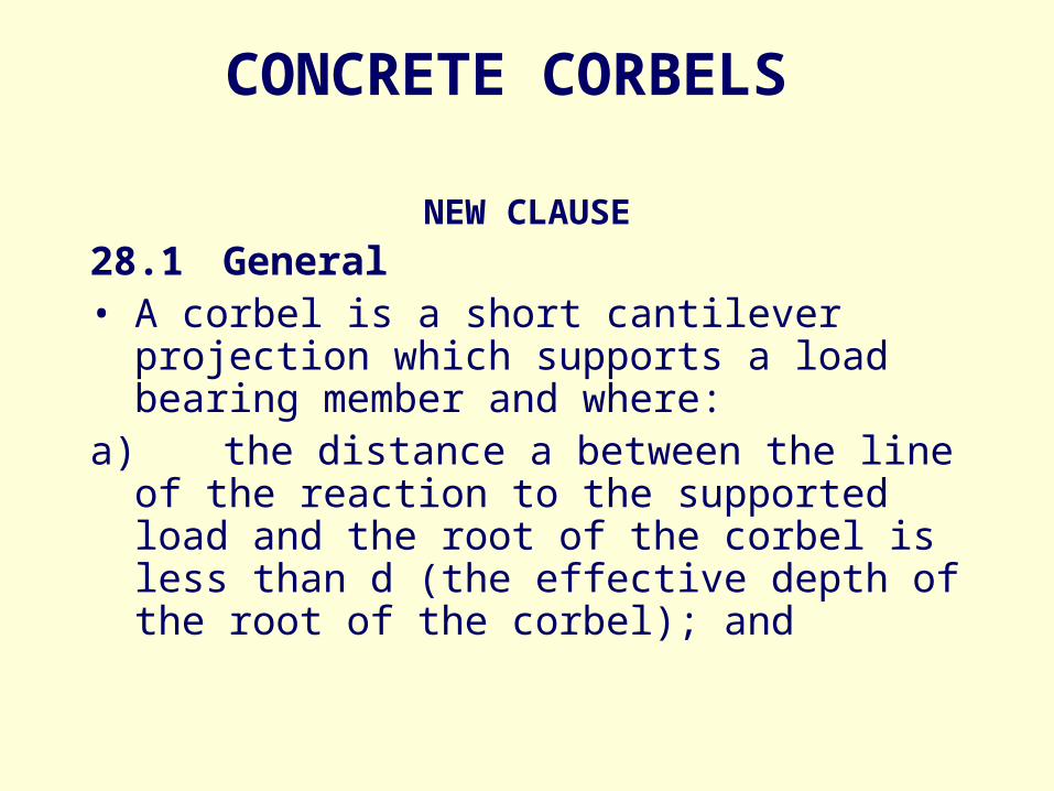
CONCRETE CORBELS
NEW CLAUSE
28.1 General• A corbel is a short cantilever projection
which supports a load bearing member and where:
a) the distance a between the line of the reaction to the supported load and the root of the corbel is less than d (the effective depth of the root of the corbel); and

CONCRETE CORBELS
NEW CLAUSEb) the depth at the outer edge of the contact area of the supported load is not less than one-half of the depth at the root of the corbel.The depth of the corbel at the face of the support is determined from shear consideration in accordance with 40.5.2 but using the modified definition of av given in (a).
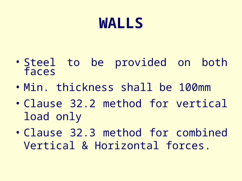
WALLS
• Steel to be provided on both faces
• Min. thickness shall be 100mm
• Clause 32.2 method for vertical load only
• Clause 32.3 method for combined Vertical & Horizontal forces.

21. FIRE RESISTANCE
Durability removed ( & made into a new Chapter.)
IS:1641 for fire resistance in hrs.– Member size– Detailing– Cover– Types of aggregate
IS:1642 for Fire Protection
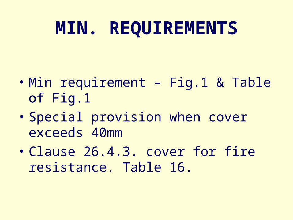
MIN. REQUIREMENTS
• Min requirement – Fig.1 & Table of Fig.1
• Special provision when cover exceeds 40mm
• Clause 26.4.3. cover for fire resistance. Table 16.
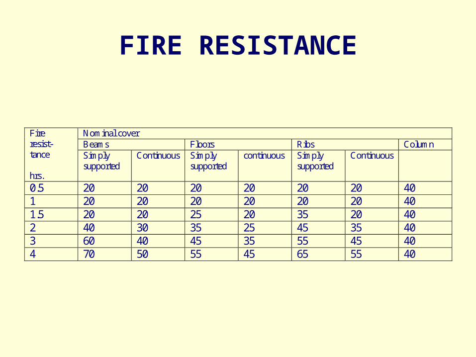
FIRE RESISTANCE
Nominal cover Beams Floors Ribs Column
Fire resist- tance hrs.
Simply supported
Continuous Simply supported
continuous Simply supported
Continuous
0.5 20 20 20 20 20 20 40 1 20 20 20 20 20 20 40 1.5 20 20 25 20 35 20 40 2 40 30 35 25 45 35 40 3 60 40 45 35 55 45 40 4 70 50 55 45 65 55 40
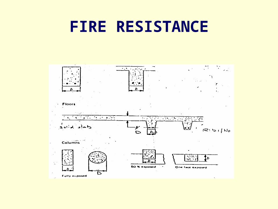
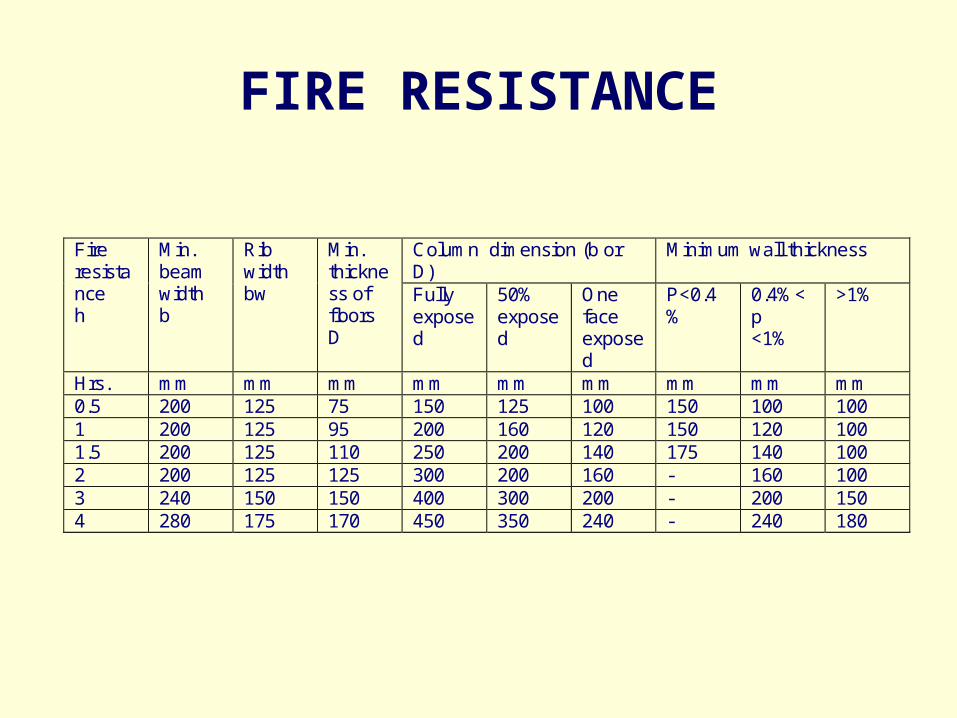
FIRE RESISTANCE
FIRE RESISTANCE
Column dimension (b or D)
Minimum wall thickness Fire resistance h
Min. beam width b
Rib width bw
Min. thickness of floors D
Fully exposed
50% exposed
One face exposed
P<0.4%
0.4%<p <1%
>1%
Hrs. mm mm mm mm mm mm mm mm mm 0.5 200 125 75 150 125 100 150 100 100 1 200 125 95 200 160 120 150 120 100 1.5 200 125 110 250 200 140 175 140 100 2 200 125 125 300 200 160 - 160 100 3 240 150 150 400 300 200 - 200 150 4 280 175 170 450 350 240 - 240 180

Section 6 Steel
• IS 800 : 1984 Code of practice for general construction in steel (second revision)
• IS 806: 1968 code of practice for use of steel tubes in general building construction (first revision)
• IS 800 is undergoing revision• Introduction of limit state design• Plastic range of material for design
of structural members• Ultimate limit state and serviceability
limit state• Incorporatea load factors• Tension and compression have
different performance factors• Critical buckling stress considering
local buckling of members classified as slender, semi-compact, compact and Plastic.
• Section 7
• Prefabrication systems Buildings
• And mixed /composite Construction
• 7A Prefabricated Concrete

7A Prefabricated Concrete
• Importance aesthetics highlighted• Clauses on materials added• Clauses on prefabrication systems and
structural elements elaborated• Clauses on testing of components revised• Manufacture of cellular concrete added

7A Prefabricated Concrete
• Modular coordination and modular dimension of components revised bring about more flexibility in planning
• Provisions for tolerance revised to include different types of prefabricated components
• Detailed clause on safety requirements against progressive collapse added

Systems Buildings and Mixed/composite Construction
• Prescribes general requirements applicable to all valid existing systems and mixed/composite constructions
• Flexibility to accommodate new systems introduced in future is also incorporated

Jose KurianChief Engineer, DTTDC