Structural Design for a Neptune Aerocapture...
13
Structural Design for a Neptune Aerocapture Mission R. Eric Dyke* Swales Aerospace, NASA Langley Research Center, Hampton, VA 23681 Glenn A. Hrinda† NASA Langley Research Center, Hampton, VA 23681 A multi-center study was conducted in 2003 to assess the feasibility of and technology requirements for using aerocapture to insert a scientific platform into orbit around Neptune. The aerocapture technique offers a potential method of greatly reducing orbiter mass and thus total spacecraft launch mass by minimizing the required propulsion system mass. This study involved the collaborative efforts of personnel from Langley Research Center (LaRC), Johnson Space Flight Center (JSFC), Marshall Space Flight Center (MSFC), Ames Research Center (ARC), and the Jet Propulsion Laboratory (JPL). One aspect of this effort was the structural design of the full spacecraft configuration, including the ellipsled aerocapture orbiter and the in-space solar electric propulsion (SEP) module/cruise stage. This paper will discuss the functional and structural requirements for each of these components, some of the design trades leading to the final configuration, the loading environments, and the analysis methods used to ensure structural integrity. It will also highlight the design and structural challenges faced while trying to integrate all the mission requirements. Component sizes, materials, construction methods and analytical results, including masses and natural frequencies, will be presented, showing the feasibility of the resulting design for use in a Neptune aerocapture mission. Lastly, results of a post-study structural mass optimization effort on the ellipsled will be discussed, showing potential mass savings and their influence on structural strength and stiffness Nomenclature Al = aluminum ARC = Ames Research Center AU = astronomical units B/S = backshell CBE = current best estimate CG = center of gravity F/B = forebody FEA = finite element analysis FEM = finite element model FS = factor of safety Gr = graphite HGA = high gain antenna JPL = Jet Propulsion Laboratory JSFC = Johnson Space Flight Center LaRC = Langley Research Center L/D = lift/drag _______________________________________ *Structural Engineer, Swales Aerospace/Vehicle Analysis Branch, MS360 †Structural Engineer, Vehicle Analysis Branch, Aerospace Systems Concepts and Analysis Competency, MS353X American Institute of Aeronautics and Astronautics 1
Transcript of Structural Design for a Neptune Aerocapture...
Structural Design for a Neptune Aerocapture Mission
R. Eric Dyke* Swales Aerospace, NASA Langley Research Center, Hampton, VA 23681
Glenn A. Hrinda†
NASA Langley Research Center, Hampton, VA 23681
A multi-center study was conducted in 2003 to assess the feasibility of and technology requirements for using aerocapture to insert a scientific platform into orbit around Neptune. The aerocapture technique offers a potential method of greatly reducing orbiter mass and thus total spacecraft launch mass by minimizing the required propulsion system mass. This study involved the collaborative efforts of personnel from Langley Research Center (LaRC), Johnson Space Flight Center (JSFC), Marshall Space Flight Center (MSFC), Ames Research Center (ARC), and the Jet Propulsion Laboratory (JPL). One aspect of this effort was the structural design of the full spacecraft configuration, including the ellipsled aerocapture orbiter and the in-space solar electric propulsion (SEP) module/cruise stage. This paper will discuss the functional and structural requirements for each of these components, some of the design trades leading to the final configuration, the loading environments, and the analysis methods used to ensure structural integrity. It will also highlight the design and structural challenges faced while trying to integrate all the mission requirements. Component sizes, materials, construction methods and analytical results, including masses and natural frequencies, will be presented, showing the feasibility of the resulting design for use in a Neptune aerocapture mission. Lastly, results of a post-study structural mass optimization effort on the ellipsled will be discussed, showing potential mass savings and their influence on structural strength and stiffness
Nomenclature Al = aluminum ARC = Ames Research Center AU = astronomical units B/S = backshell CBE = current best estimate CG = center of gravity F/B = forebody FEA = finite element analysis FEM = finite element model FS = factor of safety Gr = graphite HGA = high gain antenna JPL = Jet Propulsion Laboratory JSFC = Johnson Space Flight Center LaRC = Langley Research Center L/D = lift/drag _______________________________________
*Structural Engineer, Swales Aerospace/Vehicle Analysis Branch, MS360 †Structural Engineer, Vehicle Analysis Branch, Aerospace Systems Concepts and Analysis Competency, MS353X
American Institute of Aeronautics and Astronautics
1
misty.cahill
Text Box
AIAA Paper 2004-5179; AIAA Atmospheric Flight Mechanics Conference and Exhibit, Providence, RI, United States, 16-19 Aug. 2004 , 20040101; [2004]

MAC = mass acceleration curve MEL = master equipment list MS = margin of safety MSFC = Marshall Space Flight Center NSM = non-structural mass OML = outer mold line PAF = payload adapter fitting PM = propulsion module SA = solar array SEP = solar electric propulsion TPS = thermal protection system Xe = Xenon
I. Introduction
S tructural sizing for a conceptual aerocapture spacecraft to Neptune was required to establish concept feasibility and to obtain preliminary component mass estimates. The full spacecraft launch stackup consisted of an
ellipsled aerocapture/orbiter vehicle sitting atop a propulsion module (PM)/cruise stage, all designed to fit within the 5 meter fairing of a Delta IV Heavy launch vehicle1. The PM/cruise stage contained the solar arrays (SA’s), Xenon (Xe) tank and other subsystems for the 30 kW, 6-engine solar electric propulsion (SEP) system to be used out to 3 AU. It also held a small hydrazine fuel tank, telecommunication antennae, navigation equipment, thermal radiators, and two Neptune direct entry atmospheric probes which were considered simple lumped masses for this study.
There were four basic objectives for the structural analysis: 1) Support all science payload and subsystem components in the required volume, 2) Meet minimum stackup natural frequencies at launch, 3) Sustain structural stresses at launch and during aerocapture with acceptable margins of safety (MS), and 4) meet the above three objectives with minimal structural mass. Objective 1) above was accomplished by multiple packaging/analysis iterations between JPL and LaRC personnel, producing several ellipsled orbiter configurations and overall size changes before an acceptable design was found. Launch loading criteria from the Boeing Payload Planners Guide2 and aerocapture loading criteria from NASA Langley Monte Carlo simulations3 were used in conjunction with the commercially available finite element analysis (FEA) software I-DEAS4 to size structure with acceptable strength and stiffness to meet objectives 2) and 3) above. I-DEAS FEA and hand calculations were used to size the ellipsled orbiter and the PM/cruise stage during the scheduled design/analysis cycle. Due to challenges in packaging all of the required payload instruments and subsystem components to meet design functionality and overall center of gravity (CG) requirements, and to the ensuing shortened time available for analysis, mass optimization was performed after the scheduled design/analysis cycle. The commercially available software HyperSizer™ 5 was used to help reduce mass on the ellipsled orbiter. No similar mass optimization effort was done on the PM/cruise stage.
The resulting structure consists of a composite material honeycomb sandwich construction ellipsled orbiter aeroshell surrounding a deep-rib stiffened honeycomb sandwich payload deck. The ellipsled orbiter aeroshell is separate forebody (F/B) and backshell (B/S) pieces integrally stiffened with longitudinal and circumferential blades. The F/B and B/S separate from the payload deck after aerocapture via several pyrotechnic separation fittings. The resulting PM/cruise stage is a stiffened Al skin with Al rings and trusses to support the hydrazine and Xe tanks and the two direct entry probes and an Al frame to support the SEP engines.
II. Functional Requirements
A. Orbiter Shape Selection Neptune atmosphere profiles developed by Justus, Duvall, and Keller6 at MSFC and Neptune atmosphere entry
parameters developed by JPL7 and LaRC3 personnel were used to determine the required aerocapture vehicle shape and aerodynamic characteristics to meet the stringent entry corridor needed for aerocapture at Neptune3. Edquist8 (LaRC) evaluated the aerodynamics of several entry vehicle shape classes, including sphere-cone, biconic, bent biconic, and ellipsled, to find an appropriate shape giving the necessary volume and aerodynamic lift to drag ratio (L/D). The resulting vehicle, as shown in Fig. 1, was an ellipsled shape with a flattened bottom. The general ellipsled shape is a body of revolution with an ellipsoid nose and circular cylinder aft end. The flattened ellipsled has an upper portion that is half a body of revolution and a lower portion that is a general ellipsoid nose and elliptical aft cylinder.
American Institute of Aeronautics and Astronautics
2

B. Orbiter and PM/Cruise StaThe primary functions of th
orbiter aerocapture using the Npayload and other subsystems, tfor launch and aerocapture loadiwere several challenges to overchigh thermal protection systempayload and other subsystem coproper overall mass CG to maiduring the full aerocapture phasthe conceptual design phase. Tsection.
The primary functions of theattachments for the two direct ecomponents; to provide sufficienand to do all of the above with stage structure was providing fotheir proper functions. The twoeach other and the ellipsled andvehicle CG. The large ellipsledmeet the stackup launch natural
A. Design Loads Design launch loads were t
summarized in Table 1 below. assumed restrained at the payloaloads from the Monte Carlo entusing an unpublished coarse prComponent level loads from maanalyzed as part of this study.
Event LoadLaunch 6.0 g’ 2.3 g’Aerocapture 22.1 g
Top
Ellipsoid Nose Portion
Top
Ellipsoid Nose Portion
Rear Iso View
Volume = 3.79 m3
Surface Area = 13.8 m2
0.414 m
1.738 m
0.869 mRear
0.414 m
1.738 m
0.869 mRear
2.145 m
Right
2.880 m
(0.735 m)2.145 m
Right
2.880 m
(0.735 m)
Cylindrical Aft End
Figure 1. Flattened Ellipsled Geometry
ge Requirements e ellipsled orbiter were to provide the aerodynamic shape necessary to facilitate eptunian atmosphere, to provide the volume necessary to package the scientific o provide sufficient structural MS for natural frequency, buckling, and static stress ng, and to do all of the above with minimal structural mass and complexity. There ome in fulfilling these functions. The ellipsled aeroshell structure had to support a (TPS) mass9 due to the high aeroheating during aerocapture10. The numerous mponents had to be packaged to allow their proper functions but also to provide ntain the required ellipsled angle of attack for aerodynamic control and stability e8, 11. There were also large variations in aerocapture g loads during the course of hese challenges required multiple ellipsled sizing iterations as detailed in a later
PM/cruise stage were to support the ellipsled during launch and cruise; to provide ntry Neptune probes, telecom antennae, thermal control radiators, and SEP system t structural MS for natural frequency, buckling, and static stress for launch loading;
minimal structural mass and complexity. The primary challenge for the PM/cruise r the numerous component attachments in a compact design without compromising direct entry probes required specific alignment to allow separation independent of to allow separation along a vector going through (or as close as possible to) the mass sitting on top during launch also required extra PM/cruise stage stiffness to frequency requirements.
III. Structural Analysis Requirements
aken from the Boeing Payload Planners Guide for the Delta IV Heavy2, and are For the static analysis and natural frequency calculations, the full stackup was d adapter fitting (PAF). Aerocapture design g loads were taken from the 3-sigma g ry analysis3, and were balanced with aeropressure loads on the ellipsled aeroshell essure distribution from N. Takashima (AMA/LaRC) dated September 12, 2003. ss acceleration curves (MAC’s), and sine, random, and acoustic loading were not
Table 1. Static Load Factors
ing s axial + 0.5g’s lateral, any direction s axial + 2.0 g’s lateral, any direction ’s, acting 11.3 degrees aft of vertical relative to ellipsled payload deck
American Institute of Aeronautics and Astronautics
3

B. Strength and Stiffness Standard strength and stability factors of safety (with verification) listed in Table 2 below were used in the
structural analysis.
Table 2. Analytical Factors of Safety
Mode Factor of Safety Metallic ultimate stress 1.4 Metallic yield stress 1.25 Stress in composites 1.4 Buckling 1.5
Stackup minimum required natural frequencies at launch, taken from the Boeing Payload Planners Guide for the Delta IV Heavy2, were >8 Hz for the fundamental lateral modes, and >30 Hz for the fundamental axial mode.
C. Analysis Methods Standard “stick and panel” finite element model (FEM) construction with 2-D (non-solid) elements was used for
all structural analyses. Components such as the two direct entry probes, radiators, science instruments, fuel tanks/fuel, etc., were modeled as lumped masses and connected to the vehicle structure using rigid-type element connectors or beam elements as appropriate. All FEM’s were constructed with I-DEAS, and solved with I-DEAS (2.88m ellipsled) or NASTRAN (5.5m ellipsled) as described below.
The structural analysis was done in two phases. First, the ellipsled was analyzed using the aerocapture pressure loads with an inertia relief solution method that balances the pressures with entry g loads. The TPS was modeled as non-structural mass (NSM) on the aeroshell elements using areal densities provided by B. Laub (ARC)9 with 30% growth factors applied. For the structural analysis, the F/B TPS areal density (55.4 kg/m2) and B/S and base TPS areal density (5.54 kg/m2) were each assumed constant, making two TPS zones. Later TPS analysis modified this to four TPS zones12 in an effort to help reduce TPS mass, but was not available in time for this structural analysis. Instruments and other subsystem components were modeled as lumped masses with 30% growth factors applied. Non-point masses such as thermal blankets, cabling, etc., were added to the payload deck as NSM with 30% growth factors applied. The ellipsled aeroshell and payload deck structure were then sized and the resulting structure masses were considered current best estimate (CBE).
For the full stackup at launch, the ellipsled structure mass was adjusted to include the 30% growth factor, with the growth portion being applied as NSM to the existing structure plate elements. The SEP/cruise stage payload components (radiators, probes, fuel tanks, etc.) were modeled as lumped masses with the 30% growth factors applied. Non-point masses such as cabling, etc., were added as NSM to the cruise stage cylinder and thrust tube. The stackup structure was then sized for the launch loads, and the resulting structure masses for the PM/cruise stage were considered CBE. After the preliminary structure sizing for static loads, the ellipsled was evaluated for buckling under aerocapture loads. The full stackup was evaluated for natural frequency and buckling in the launch configuration under launch loads.
IV. Orbiter Size Iterations
A. 5.5 m Ellipsled Design The ellipsled aeroshell was initially 5.5m long, maximized to fit in a Delta IV Heavy 5m fairing2. The length
was determined by ratioing the maximum aeroshell width that could fit inside the Delta IV fairing. This provided the largest orbiter volume for science payloads and greatest width for mounting a rigid high gain antenna (HGA). Different internal structures to support the rigid aeroshell and mount payloads were tried. Figure 2 shows an early concept using a space truss to maintain the outer mold line (OML) of the aeroshell.
American Institute of Aeronautics and Astronautics
4

Figure 2. Internal Space Truss Figure 3. Internal Payload Deck
This configuration relied on the trusses for all equipment mounting and did not require large stiffening of the shell. The load path from all payload and aeroshell mass continued through the space truss into a cruise stage adapter. The purpose of using the space truss was to minimize aeroshell mass with an efficient, highly stiff internal support system. As the design study proceeded, the payload requirements and their configurations inside the ellipsled were constantly being revised. As a result, the internal truss design became difficult to alter while trying to package the rigid HGA within the trusses. A second method was tried that used a flat, stiffened deck for mounting the payload. The flat payload platform offered a convenient surface for securing equipment and also allowed for quick component configuration changes. Figure 3 shows the flat payload deck and major components of the orbiter.
A single hydrazine tank was located near the ellipsled CG with a rigid HGA mounted as shown. The rigid antenna was oriented to fit inside the aeroshell and mounted to the payload deck. The load path for this concept had the aeroshell supporting the payload deck during launch. All loads would then be taken into an elliptic thrust adaptor and continue through to the cruise stage. The cruise stage configuration during this time of the design study was unknown so a cruise stage from an earlier design study13 was used. Figure 4 shows the FEM of the ellipsled with its adapter and cruise stage.
Figure 4. 5.5m Ellipsled with Preliminary Adapter/Cruise Stage
B. 5.5m Ellipsled Structural Analysis The 5.5m ellipsled aeroshell structure was analyzed using standard FEA combined with a non-deterministic
structural sizing program called HyperSizer™ which allows many trial composite sections and materials to be analyzed very efficiently using only one coarsely meshed FEM. The HyperSizer™ analysis started with a coarse NASTRAN14 FEM of the full stack shown in Fig. 4, subjected to launch loads. That FEM, containing only CQUAD4, CTRIA3, CONM2, and CBAR NASTRAN elements, was solved with NASTRAN and the mesh and resulting element internal loads were imported to HyperSizer™. Figures 5 and 6 show how the FEM was divided
American Institute of Aeronautics and Astronautics
5

into major components reflecting the mission of the orbiter. HyperSizer™ did not require structure remeshing to reflect structural changes necessary to support changing payload components from the master equipment list (MEL).
Figure 5. Major Aeroshell Components Figure
Detailed finite element modeling of panel stiffening methcan choose among many common aerospace structural concpanels and isogrids while still using the same coarse FEM. FigEach color shown in the figure represents a group of finite elemcards, lumped together as a component (or “panel”) when payload deck divided into four components that will each beand material.
A F/B and B/S were created and attached together at lo
Groups of finite elements were created for optimizing in Hype6. Stiffening of the payload deck and aeroshell became necessbulkhead required to support the Hydrazine tank and axial stifwas input into HyperSizer™ as NSM and could easily be alLaunch and aerocapture loading and structure stiffness requireused. An older cruise stage FEM from a previous design studcheck launch-configuration natural frequencies. Subsystem/plumped on the stiffened payload deck based on the latest desigthe design, causing many modifications to the analysis. Latedeployable antenna. This decision drastically affected the aerigid HGA was no longer required. The aeroshell volume coua final design concept requiring a 2.88m long ellipsled that study was then divided into two paths: one using a 5.5m lonalso represented the most current design and MEL. The purmaximum and minimum structural mass estimates for the systgive mission planners a maximum structural mass and internal
American Institute of Aeronau
6
Figure 6. Internal Stiffening Structure
ods was not necessary. Within HyperSizer™, a user epts such as blade-stiffened panels, honeycomb core ure 7 shows the analysis path taken by HyperSizer™. ents with common NASTRAN property and material
imported into HyperSizer™. The figure shows the sized for optimal panel stiffening method, thickness,
Figure 7. HyperSizer™ Analysis Path
cations where they would separate after aerocapture. rSizer™ and are shown as different colors in Figs. 4-ary as the analysis proceeded. Figure 6 shows a major feners to help transfer loads during launch. TPS mass tered to suit different thermal material trade studies. ments from Table 1 in the Design Loads section were y13 was used to obtain estimated full stack stiffness to ayload component masses from the latest MEL were n. Components were constantly being moved during r in the study the HGA antenna was replaced with a
roshell design since the maximum geometry to fit the ld be shrunk to minimize structural mass. This led to also represented the most current MEL. The design g ellipsled and the other using a 2.88m ellipsled that pose for having two design concepts was to provide ems study. The 5.5m ellipsled design was finished to volume if a larger ellipsled is required.
tics and Astronautics

C. 5.5m Ellipsled Structural Analysis Results The final structural member masses for the 5.5m ellipsled are shown in Table 3 below15, followed by more
detailed construction descriptions. These results were considered worst case structural mass estimates for the given aerocapture mission to Neptune.
Table 3. 5.5m Ellipsled Component Masses
Component Area (m²)
Structural Mass (kg)
TPS Mass (kg)
Heatshield (F/B) 22.47 210.54 1245.35 B/S 21.30 151.57 118.02 Payload Deck 12.88 271.48 No TPS Aft Bulkhead 6.37 40.36 35.28 Totals 673.95 1398.65
Heatshield (F/B)– 5.08 cm thick with a Hexcell 5052 Alloy Hexagonal Al Honeycomb core and 16.51 mm Gr-
Polyimide face sheets B/S– 3.39 cm thick with a Hexcell 5052 Alloy Hexagonal Al Honeycomb core and 16.51 mm Gr-Polyimide face
sheets Aft Bulkhead – 2.54 cm thick with a Hexcell 5052 Alloy Hexagonal Al Honeycomb core and 16.51 mm Gr Polyimide face sheets
Payload Deck –Al Isogrid
The two lowest lateral stack modes were 17.51 Hz and 17.93 Hz. The lowest axial mode was 49.98 Hz, involving structure for the orbiter thrusters. All local buckling checks were performed within HyperSizer™.
Honeycomb core with facesheets was used for the overall aeroshell design. It provided the lowest mass that met all stress and dynamic modes criteria for the aeroshell. The isogird design shown in Fig. 8 was selected for the scientific payload platform. The detailed geometry would have been difficult and time consuming to create with a typical FEA. HyperSizer™ was able to quickly show a payload deck isogrid design that is well suited for mounting components with ample openings for running cables and piping. The isogird design mass was roughly the same as that required for a blade stiffened payload deck using honeycomb.
Figure 8. Payload Deck Isogrid Design
As mentioned above, preliminary mass estimates and HGA design changes allowed the ellipsled to be reduced to
2.88m. Figure 9 shows a size/design comparison between the original, larger 5.5m aeroshell with old cruise stage, and the revised, smaller 2.88m ellipsled with new cruise stage, described more fully in the next sections.
American Institute of Aeronautics and Astronautics
7
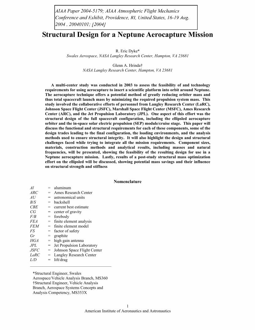
D. 2.88m Ellipsled Design After initial structure and
changes were made to use a ellipsled was reduced to 3.5 mits FEM, respectively, for thellipsled orbiter design, with
Figure 9. 5.5m and 2.88m Ellipsled Comparison
TPS mass estimates showed unacceptably high values for the 5.5m ellipsled, and deployable HGA, a parallel analysis effort was started to size a smaller ellipsled. The
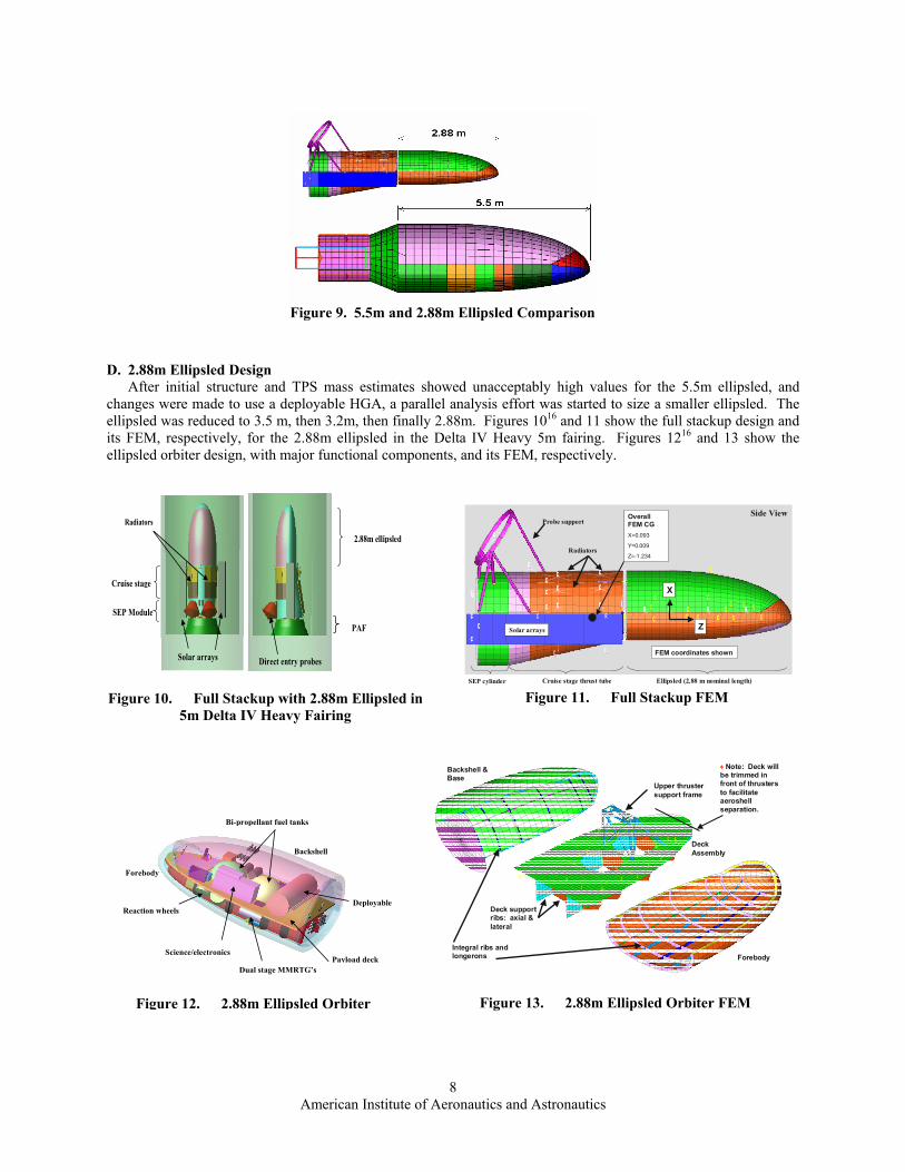
, then 3.2m, then finally 2.88m. Figures 1016 and 11 show the full stackup design and e 2.88m ellipsled in the Delta IV Heavy 5m fairing. Figures 1216 and 13 show the major functional components, and its FEM, respectively.
C
CC
CCC CC CCC
C
CC
CC
CCC C
C
C
C
C
C
C
C
C
C
C
C
CC
C
C
CC
C
C
C
C
C
C
C
C R R R RRRRR
C
C
CC C CCCCCCC
C
R
C
C
CC
CC
CCC CC CCC
C
CC
CC
CCC C
C
C
C
C
C
C
C
C
C
C
C
CC
C
C
CC
C
C
C
C
C
C
C
C R R R RRRRR
C
C
CC C CCCCCCC
C
R
C
C
C
Ellipsled (2.88 m nominal length)Cruise stage thrust tubeSEP cylinder
Radiators
Probe support
Solar arrays
Side View
Z
X
FEM coordinates shown
Overall FEM CGX=0.093
Y=0.009
Z=-1.234
Figure 11. Full Stackup FEM
2.88m ellipsled
PAF
Cruise stage
SEP Module
Solar arrays Direct entry probes
Radiators
Figure 10. Full Stackup with 2.88m Ellipsled in 5m Delta IV Heavy Fairing
CC
C
C
C
C
C
CC
C
C
C
C
CC
C
C
C
C
C
C
C
C
CC
CC
C
CC
C
C
C
C
C
CC
C
C
C
C
CC
C
C
C
C
C
C
C
C
CC
CC
C
Backshell & Base
Deck Assembly
ForebodyIntegral ribs and longerons
Deck support ribs: axial & lateral
Upper thruster support frame
♦Note: Deck will be trimmed in front of thrusters to facilitate aeroshell separation.
Figure 13. 2.88m Ellipsled Orbiter FEM
Backshell
Forebody
Deployable Reaction wheels
Science/electronics
Dual stage MMRTG’s
Bi-propellant fuel tanks
Payload deck
Figure 12. 2.88m Ellipsled Orbiter
American Institute of Aeronautics and Astronautics
8

The F/B and B/S base are uniform 2.54 cm thick sandwich structure with 5052 Al honeycomb and 0.132 cm Gr-Polyimide facesheets, stiffened with 0.318 cm thick integral monolithic composite blade longerons and circumferential ribs. The payload deck is also a 2.54 cm thick sandwich structure with 5052 Al honeycomb and 0.132 cm Gr-Polyimide facesheets. It is stiffened with full-depth lateral and longitudinal sandwich structure ribs, 1.27 cm thick with 5052 Al honeycomb and 0.132 cm Gr-Polyimide facesheets. The bi-propellant fuel tanks are further supported by small Al tube struts under the deck. The upper frame is 2.54 cm x 2.54 cm x 0.130 cm Al angles, and supports thrusters for on-orbit attitude control. The ellipsled is tied to the PM/cruise stage with eight pyrotechnic fittings which separate the ellipsled from the cruise stage prior to aerocapture. The payload deck is tied to the F/B and B/S base with twenty separation fittings which fire after aerocapture to separate the F/B and B/S, leaving the payload deck on orbit. During aerocapture, the component inertia loads from the orbiter’s high-g deceleration are transmitted across the payload deck panels, into the ribs, then into the aeroshell (primarily the F/B), where they are balanced by the aeropressure loads on the aeroshell exterior.
Figures 1416 and 15 show the PM/cruise stage design with functional components, and its FEM representation with major structural components, respectively. Both the SEP cylinder and cruise stage thrust tube are stiffened skin construction. The 0.254 cm Al skin is stiffened by a series of Al longerons and rings, as shown in Fig. 16, which transmit launch loads into the PAF and provide hard points for component attachments such as the hydrazine and Xe tanks, SA’s, radiators, etc. An Al ring frame at the bottom of the SEP cylinder, stiffened by 5.08 cm Al tube struts, provides attach points for the six SEP engines. The two entry probes are supported by 5.08 cm Al channel-section rings with 5.08 cm Al tube trusses. The Xe tank is supported by a 5.08 cm Al channel-section ring and 5.08 cm Al tube struts at the bottom, and 2.54 cm Al tube struts at the top. The hydrazine tank is supported by a single Al ring with stiffening struts. During launch, the ellipsled inertia loads enter the PM/cruise stage via the eight separation fittings. The inertia loads from the individual PM/cruise stage components enter the stiffened skin structure through their respective support structure. All of these loads are then transmitted down the stiffened skin, eventually being reacted at the PAF.
Probes
Gimballed L-Band Probe Relay AntennaGimballed X/Ka-Band Antenna
1 (of 2) Gimballed Optical Navigation Cameras
Hydrazine Tank
Xenon Tank
MR-111s
Hydrazine Tank
Figure 14. PM/Cruise Stage Components
C
CC
C
C
C
C
C
C
C
C
C
CC
C
CC
C
C
C
C
C
CC
CC
C
CC
C
C
C
C
C
CC
C
C
C
C
C
C
C
C
C
CC
C
CC
C
C
C
C
C
CC
CC
C
CC
C
C
C
C
Solar arrays
Probe supports & concentrated masses
SEP engine support
Cruise stage aluminum skin
Figure 15. PM/Cruise Stage FEM
Am
SEP/cruise stage stiffening longerons and ringsXe tank
lower support
Xe tank upper support
Hydrazine tank support
Figure 16. PM/Cruise Stage FEM showing internal longerons and rings
erican Institute of Aeronautics and Astronautics
9
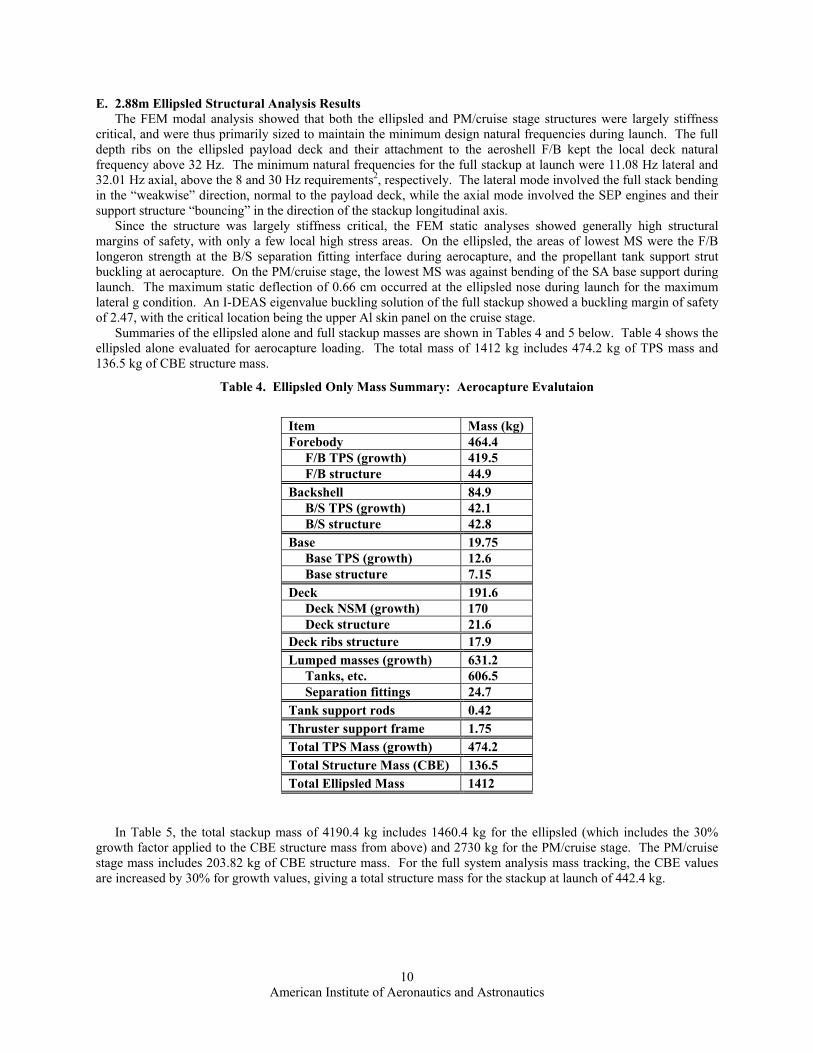
E. 2.88m Ellipsled Structural Analysis Results The FEM modal analysis showed that both the ellipsled and PM/cruise stage structures were largely stiffness
critical, and were thus primarily sized to maintain the minimum design natural frequencies during launch. The full depth ribs on the ellipsled payload deck and their attachment to the aeroshell F/B kept the local deck natural frequency above 32 Hz. The minimum natural frequencies for the full stackup at launch were 11.08 Hz lateral and 32.01 Hz axial, above the 8 and 30 Hz requirements2, respectively. The lateral mode involved the full stack bending in the “weakwise” direction, normal to the payload deck, while the axial mode involved the SEP engines and their support structure “bouncing” in the direction of the stackup longitudinal axis.
Since the structure was largely stiffness critical, the FEM static analyses showed generally high structural margins of safety, with only a few local high stress areas. On the ellipsled, the areas of lowest MS were the F/B longeron strength at the B/S separation fitting interface during aerocapture, and the propellant tank support strut buckling at aerocapture. On the PM/cruise stage, the lowest MS was against bending of the SA base support during launch. The maximum static deflection of 0.66 cm occurred at the ellipsled nose during launch for the maximum lateral g condition. An I-DEAS eigenvalue buckling solution of the full stackup showed a buckling margin of safety of 2.47, with the critical location being the upper Al skin panel on the cruise stage.
Summaries of the ellipsled alone and full stackup masses are shown in Tables 4 and 5 below. Table 4 shows the ellipsled alone evaluated for aerocapture loading. The total mass of 1412 kg includes 474.2 kg of TPS mass and 136.5 kg of CBE structure mass.
Table 4. Ellipsled Only Mass Summary: Aerocapture Evalutaion
Item Mass (kg) Forebody 464.4 F/B TPS (growth) 419.5 F/B structure 44.9 Backshell 84.9 B/S TPS (growth) 42.1 B/S structure 42.8 Base 19.75 Base TPS (growth) 12.6 Base structure 7.15 Deck 191.6 Deck NSM (growth) 170 Deck structure 21.6 Deck ribs structure 17.9 Lumped masses (growth) 631.2 Tanks, etc. 606.5 Separation fittings 24.7 Tank support rods 0.42 Thruster support frame 1.75 Total TPS Mass (growth) 474.2 Total Structure Mass (CBE) 136.5 Total Ellipsled Mass 1412
In Table 5, the total stackup mass of 4190.4 kg includes 1460.4 kg for the ellipsled (which includes the 30% growth factor applied to the CBE structure mass from above) and 2730 kg for the PM/cruise stage. The PM/cruise stage mass includes 203.82 kg of CBE structure mass. For the full system analysis mass tracking, the CBE values are increased by 30% for growth values, giving a total structure mass for the stackup at launch of 442.4 kg.
American Institute of Aeronautics and Astronautics
10

Table 5. Full Stackup Mass Summary at Launch
Components Mass (kg) Ellipsled Total 1460.4 Aeroshell total 597.81 Forebody total 478.1 F/B TPS 419.5 F/B
structure 58.6
Backshell total 97.81 B/S TPS 42.12 B/S
structure 55.69
Base total 21.9 Base TPS 12.61 Base
structure 9.29
Payload total 803 Deck total 198.1 Deck NSM 170 Deck
structure 28.1
Deck rib structure
23.29
Thruster support 1.75 Tank support
rods 0.42
Lumped masses 606.5 Separation fittings 32.11 Cruise stage total 2730 SEP cylinder
total 144.6
NSM 114.82 Structure 29.78 Thrust tube total 168.2 NSM 78.32 Structure 89.89 Probe support 31.32 Hydrazine tank
support 3.4
SEP Engine support
30.28
Solar array support
3.54
Solar arrays 400.4 XE tank support 15.61 Lumped masses 1932 Total stackup 4190.4
American Institute of Aeronautics and Astronautics
11

V. Post-Study Evaluation with Hypersizer™ Due to the numerous iterations involved in integrating the required system/payload components and associated
support structure into the available volume allowed by the 2.88m flattened ellipsled shape, structural mass optimization was not performed within the original design schedule. Shortly after the systems review for the Neptune Aerocapture study (October 28, 29, 2003), further analysis was performed on the 2.88m ellipsled using HyperSizer™ in an effort to realize some gains by optimizing the ellipsled structure mass. As discussed earlier, HyperSizer™ reads in the FEM mesh and internal loads from an outside FEA (in this case I-DEAS), then steps through a user-defined design space, applying the internal loads to local model regions called panels. While not a true optimizer, HyperSizer™ uses closed form solutions to step through all user-specified material, size, and construction method permutations for each model panel to find the lightest structure to pass all strength and stability requirements. This can result in adjacent panels having totally different sizing or construction techniques. While the result may yield the lightest possible structure, it is often not a manufacturable one. The user may then need to adjust the design space or link certain panels for the sake of manufacturability and rerun HyperSizer™. Lastly, since HyperSizer™ only checks local panel buckling modes and natural frequencies, the full FEM must be re-evaluated in the FEA code for global stability and natural frequencies.
For the mass optimization on the ellipsled structure, only the sandwich construction family of panels was looked at. This was primarily due to previous experience with this type of structure15 and due to time limitations. As a result of the HyperSizer™ analysis, the ellipsled structure mass was reduced by 39.1 kg, from 134.4 kg (the upper thruster frame and propulsion tank supports were not evaluated) to 95.3 kg. The first pass through HyperSizer™ showed a 56.2 kg mass reduction, but all of this could not be realized when adjustments were made for structure manufacturability. The resulting structure was re-evaluated in I-DEAS to check global stability and natural frequencies. As a result of reducing mass without significant stiffness reduction, the overall stackup natural frequency climbed slightly from 11.08 Hz to 11.84 Hz. For the ellipsled only at aerocapture, the global buckling margin of safety increased from 1.97 to 2.51. For the full stackup, the global buckling margin increased from 2.47 to 3.15.
VI. Conclusions A successful aerocapture mission at Neptune depends on success of many subsystems, including structure that
will house and support the required payload, sustain launch loads, sustain aerocapture inertia loads and heating, and provide all of the above with a minimum mass. The structural analysis portion of the Neptune aerocapture systems design study showed that the chosen stackup design of a stiffened-skin construction PM/cruise stage supporting a 2.88m ellipsled aerocapture vehicle is a feasible approach when using a Delta IV Heavy launch vehicle, and that the stiffened sandwich ellipsled structure design is a feasible approach for aerocapture at Neptune. The resulting structure masses were within system allocations and allowed a total spacecraft mass that would meet the mission requirements. The results of this study may serve as a starting point for more refined analyses of a Neptune aerocapture ellipsled and cruise stage. In addition, several observations were made from the study results:
1. The flattened ellipsled shape was volumetrically inefficient in that CG requirements pushed components towards the bottom of the ellipsled, leaving the upper portion largely unused.
2. The MEL was under constant revision and was not connected to a 3D model that could be imported into I-DEAS. Analysis and MEL should be completely integrated to allow the analysts the most updated design information.
3. The aeroshell sizing and payload support structure sizing were strongly linked, and required numerous separation fittings to provide load paths from the payload deck to the aeroshell. Further analysis and optimization is warranted to help reduce this separation system complexity.
4. The use of HyperSizer™ sizing software in this study demonstrated its capabilities to the design study team and displayed how it may be applied to ellipsled geometry. The software greatly reduced analysis time by using the same finite element mesh for many trial configurations. Typical FEA modeling of bladed stiffened panels would have the analysts modeling separate stiffeners and requiring a remesh after each solution of the model. HyperSizer™ avoids this and allows many trial iterations in one solution. Further mass reduction may be possible by applying HyperSizer™ to the cruise stage structure.
VII. Acknowledgements The author wishes to acknowledge the following people for their contributions to the Neptune aerocapture
system structural analysis: Nora Okong’o and Rob Bailey (JPL) for their work in packaging the ellipsled and cruise
American Institute of Aeronautics and Astronautics
12
American Institute of Aeronautics and Astronautics
13
stage payloads within the constraints of the structural layout; Bernie Laub (ARC) for the TPS sizing on the ellipsled forebody and backshell; and Glenn Hrinda (LaRC) for the initial structural sizing on the 5.5m aeroshell and for guidance in using HyperSizer™.
VIII. References 1Lockwood, M.K., “Overview”, Neptune Aerocapture Systems Analysis Review, Marshall Space Flight Center, Huntsville,
AL, October 28, 29, 2003. 2“Delta IV Payload Planners Guide”, The Boeing Company, Huntington Beach, CA, 2000. 3Starr, B.R., and Powell, R.W., “Simulation, Monte Carlo, Performance”, Neptune Aerocapture Systems Analysis Review,
Marshall Space Flight Center, Huntsville, AL, October 28, 29, 2003. 4EDS PLM Solutions I-DEAS software versions 9 and higher, Electronic Data Systems Corporation, Plano, TX. 5Collier Research Corporation, HyperSizer™ Structural Sizing Software, Book 1: Tutorial & Applications, Second Edition,
Collier Research Corporation, October 1998. 6Justus, C.G., Duvall, A., and Keller, V., “Atmosphere”, Neptune Aerocapture Systems Analysis Review, Marshall Space
Flight Center, Huntsville, AL, October 28, 29, 2003. 7Noca, M., “Mission Analysis”, Neptune Aerocapture Systems Analysis Review, Marshall Space Flight Center, Huntsville,
AL, October 28, 29, 2003. 8Edquist, K.T., “Configuration & Aerodynamics”, Neptune Aerocapture Systems Analysis Review, Marshall Space Flight
Center, Huntsville, AL, October 28, 29, 2003. 9Laub, B., and Chen, Y.K., “Preliminary TPS Sizing for Neptune Aerocapture”, Powerpoint Presentation, April 10, 2003. 10Hollis, B.R., and Olejniczak, J., “Aeroheating Environments”, Neptune Aerocapture Systems Analysis Review, Marshall
Space Flight Center, Huntsville, AL, October 28, 29, 2003. 11Hoffman, D., and Rea, J., “Aerodynamic Stability Analysis”, Neptune Aerocapture Systems Analysis Review, Marshall
Space Flight Center, Huntsville, AL, October 28, 29, 2003. 12Laub, B., and Chen, Y.K., “Thermal Protection (TPS)”, Neptune Aerocapture Systems Analysis Review, Marshall Space
Flight Center, Huntsville, AL, October 28, 29, 2003. 13Lam, J., “Spacecraft Structure”, Titan Aerocapture Systems Analysis Review, Jet Propulsion Laboratory, Pasadena, CA,
August 29, 30, 2002. 14MSC/NASTRAN Quick Reference Guide, The MacNeal-Schwendler Corporation, 1992. 15Hrinda, G.A., “Structure for the 5.5 m Ellipsled”, Neptune Aerocapture Systems Analysis Review, Marshall Space Flight
Center, Huntsville, AL, October 28, 29, 2003. 16Bailey, R.W., Okong’o, N., Spilker, T., and Dyke, R.E., “Spacecraft Configuration”, Neptune Aerocapture Systems
Analysis Review, Marshall Space Flight Center, Huntsville, AL, October 28, 29, 2003.