
STRUCTURAL CONCEPT AND DESIGN OF A GFRP-POLYURETHANE SANDWICH ROOF STRUCTURE · ·...
6
STRUCTURAL CONCEPT AND DESIGN OF A GFRP-POLYURETHANE SANDWICH ROOF STRUCTURE S. Yanes-Armas 1 and T. Keller 1 1 Composite Construction Laboratory (CCLab), Ecole Polytechnique Fédérale de Lausanne (EPFL), Switzerland Email: [email protected] ABSTRACT This work presents the concept and structural design of a 1000-m 2 glass fiber-reinforced polymer (GFRP) sandwich roof replacing a timber roof over an indoor swimming pool. The advantages offered by the lightweight, multifunctional GFRP-polyurethane (PUR) sandwich construction for the roof replacement are described. The roof structure was designed for two potential construction scenarios (with and without including a green rooftop), whose pertinent dead loads on the roof significantly differed. The resulting designs for both cases, considering long-term effects and applying two design recommendations (Eurocomp and BÜV) are compared and discussed. KEYWORDS Sandwich structures, roof, GFRP, polyurethane, structural design. INTRODUCTION Within the framework of renovation works, the existing timber roof of the CLP building in Switzerland is replaced by a glass fiber-reinforced polymer (GFRP) sandwich roof. The top floor of the CLP building accommodates two main uses, namely an indoor swimming pool and a reception zone (see plan view in Figure 1(a)). The almost entire top floor is currently covered by an approximately 1000-m 2 area (up to 54-m length by up to 23-m width) flat green timber roof with triangular openings for zenithal daylighting. Based on architectural and aesthetic considerations, the new roof aims to provide the swimming bath’s inside space with architectural spatial effects while maintaining illumination through natural light and virtually preserving the nearly trapezoidal perimeter geometry of the original timber roof. Furthermore, the new roof structure has to be borne by the underlying vertical structure within its limited load-bearing capacity, therefore preventing the need for structural reinforcement. The existing structure consists of prefabricated steel/concrete columns around the swimming pool and along the North and East facades delimiting the reception zone, as well of reinforced concrete core walls which allocate the technical building equipment and create the spatial division between the two building uses, see Figure 1(a). Besides, demanding serviceability and durability requirements, in particular the high operating temperature and relative humidity in the swimming pool environment, had to be met. Figure 1 (a) Plan view of CLP Building, dimensions in [m]; (b) panel arrangement of CLP sandwich roof Following the architectural concept, double-curved enclosure shapes enabling the introduction of natural light across the arising openings are designed for the swimming pool area, as shown in Figure 2. On the other hand,
Transcript of STRUCTURAL CONCEPT AND DESIGN OF A GFRP-POLYURETHANE SANDWICH ROOF STRUCTURE · ·...

STRUCTURAL CONCEPT AND DESIGN OF A GFRP-POLYURETHANE SANDWICH ROOF STRUCTURE
S. Yanes-Armas 1and T. Keller 1 1 Composite Construction Laboratory (CCLab), Ecole Polytechnique Fédérale de Lausanne (EPFL), Switzerland
Email: [email protected] ABSTRACT This work presents the concept and structural design of a 1000-m2 glass fiber-reinforced polymer (GFRP) sandwich roof replacing a timber roof over an indoor swimming pool. The advantages offered by the lightweight, multifunctional GFRP-polyurethane (PUR) sandwich construction for the roof replacement are described. The roof structure was designed for two potential construction scenarios (with and without including a green rooftop), whose pertinent dead loads on the roof significantly differed. The resulting designs for both cases, considering long-term effects and applying two design recommendations (Eurocomp and BÜV) are compared and discussed. KEYWORDS Sandwich structures, roof, GFRP, polyurethane, structural design. INTRODUCTION Within the framework of renovation works, the existing timber roof of the CLP building in Switzerland is replaced by a glass fiber-reinforced polymer (GFRP) sandwich roof. The top floor of the CLP building accommodates two main uses, namely an indoor swimming pool and a reception zone (see plan view in Figure 1(a)). The almost entire top floor is currently covered by an approximately 1000-m2 area (up to 54-m length by up to 23-m width) flat green timber roof with triangular openings for zenithal daylighting. Based on architectural and aesthetic considerations, the new roof aims to provide the swimming bath’s inside space with architectural spatial effects while maintaining illumination through natural light and virtually preserving the nearly trapezoidal perimeter geometry of the original timber roof. Furthermore, the new roof structure has to be borne by the underlying vertical structure within its limited load-bearing capacity, therefore preventing the need for structural reinforcement. The existing structure consists of prefabricated steel/concrete columns around the swimming pool and along the North and East facades delimiting the reception zone, as well of reinforced concrete core walls which allocate the technical building equipment and create the spatial division between the two building uses, see Figure 1(a). Besides, demanding serviceability and durability requirements, in particular the high operating temperature and relative humidity in the swimming pool environment, had to be met.
Figure 1 (a) Plan view of CLP Building, dimensions in [m]; (b) panel arrangement of CLP sandwich roof
Following the architectural concept, double-curved enclosure shapes enabling the introduction of natural light across the arising openings are designed for the swimming pool area, as shown in Figure 2. On the other hand,
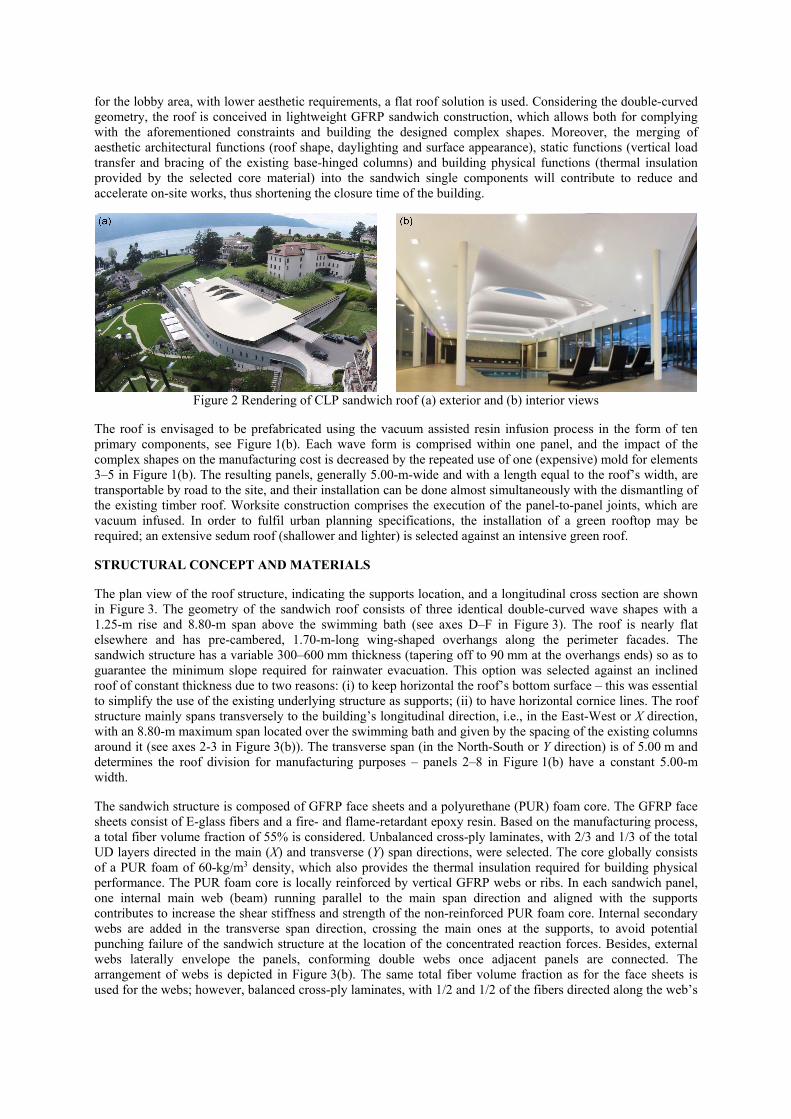
for the lobby area, with lower aesthetic requirements, a flat roof solution is used. Considering the double-curved geometry, the roof is conceived in lightweight GFRP sandwich construction, which allows both for complying with the aforementioned constraints and building the designed complex shapes. Moreover, the merging of aesthetic architectural functions (roof shape, daylighting and surface appearance), static functions (vertical load transfer and bracing of the existing base-hinged columns) and building physical functions (thermal insulation provided by the selected core material) into the sandwich single components will contribute to reduce and accelerate on-site works, thus shortening the closure time of the building.
Figure 2 Rendering of CLP sandwich roof (a) exterior and (b) interior views
The roof is envisaged to be prefabricated using the vacuum assisted resin infusion process in the form of ten primary components, see Figure 1(b). Each wave form is comprised within one panel, and the impact of the complex shapes on the manufacturing cost is decreased by the repeated use of one (expensive) mold for elements 3–5 in Figure 1(b). The resulting panels, generally 5.00-m-wide and with a length equal to the roof’s width, are transportable by road to the site, and their installation can be done almost simultaneously with the dismantling of the existing timber roof. Worksite construction comprises the execution of the panel-to-panel joints, which are vacuum infused. In order to fulfil urban planning specifications, the installation of a green rooftop may be required; an extensive sedum roof (shallower and lighter) is selected against an intensive green roof. STRUCTURAL CONCEPT AND MATERIALS The plan view of the roof structure, indicating the supports location, and a longitudinal cross section are shown in Figure 3. The geometry of the sandwich roof consists of three identical double-curved wave shapes with a 1.25-m rise and 8.80-m span above the swimming bath (see axes D–F in Figure 3). The roof is nearly flat elsewhere and has pre-cambered, 1.70-m-long wing-shaped overhangs along the perimeter facades. The sandwich structure has a variable 300–600 mm thickness (tapering off to 90 mm at the overhangs ends) so as to guarantee the minimum slope required for rainwater evacuation. This option was selected against an inclined roof of constant thickness due to two reasons: (i) to keep horizontal the roof’s bottom surface – this was essential to simplify the use of the existing underlying structure as supports; (ii) to have horizontal cornice lines. The roof structure mainly spans transversely to the building’s longitudinal direction, i.e., in the East-West or X direction, with an 8.80-m maximum span located over the swimming bath and given by the spacing of the existing columns around it (see axes 2-3 in Figure 3(b)). The transverse span (in the North-South or Y direction) is of 5.00 m and determines the roof division for manufacturing purposes – panels 2–8 in Figure 1(b) have a constant 5.00-m width. The sandwich structure is composed of GFRP face sheets and a polyurethane (PUR) foam core. The GFRP face sheets consist of E-glass fibers and a fire- and flame-retardant epoxy resin. Based on the manufacturing process, a total fiber volume fraction of 55% is considered. Unbalanced cross-ply laminates, with 2/3 and 1/3 of the total UD layers directed in the main (X) and transverse (Y) span directions, were selected. The core globally consists of a PUR foam of 60-kg/m3 density, which also provides the thermal insulation required for building physical performance. The PUR foam core is locally reinforced by vertical GFRP webs or ribs. In each sandwich panel, one internal main web (beam) running parallel to the main span direction and aligned with the supports contributes to increase the shear stiffness and strength of the non-reinforced PUR foam core. Internal secondary webs are added in the transverse span direction, crossing the main ones at the supports, to avoid potential punching failure of the sandwich structure at the location of the concentrated reaction forces. Besides, external webs laterally envelope the panels, conforming double webs once adjacent panels are connected. The arrangement of webs is depicted in Figure 3(b). The same total fiber volume fraction as for the face sheets is used for the webs; however, balanced cross-ply laminates, with 1/2 and 1/2 of the fibers directed along the web’s

length and height, respectively, are selected instead. The main mechanical properties of the GFRP laminates, both for the face sheets and for the webs, and of the PUR foam are listed in Tables 1 and 2.
Figure 3 Sandwich roof concept: (a) longitudinal cross section; (b) plan view with elements arrangement,
internal webs and supports, dimensions in [m] Table 1 Properties of GFRP laminates, average values calculated based on selected fiber content and architecture
Property Symbol Value
Face sheet laminate Web laminate Elastic modulus EL,x,m 29 GPa 23 GPa
EL,y,m 18 GPa 23 GPa Shear modulus GL,xy,m 2.4 GPa 2.4 GPa
Table 2 Properties of PUR foam, characteristic values from Keller et al. (2008)
Property Symbol ValueShear strength τC,k 0.25 MPa
Elastic modulus EC,k 17.5 MPaShear modulus GC,k 6.5 MPa
STRUCTURAL DESIGN The sandwich roof was designed for two potential construction scenarios: (i) A roof: the sandwich finishing surface provides the roof’s exterior appearance, i.e., no additional construction elements are added above; (ii) B roof: a sedum green roof of 170-kg/m2-weight is installed on the top. The structural design was carried out according to the requirements of Swiss standards (SIA), namely SIA260 (2013) and SIA261 (2014), which are consistent with the corresponding Eurocodes. The partial safety factor concept, with partial factors applied both on the action and material sides (load and resistance factors, respectively), was used. The following actions were considered: permanent loads (self-weight of the sandwich structure and roof system) and snow; their associated load factors were determined from SIA260 (2013). Material resistance factors were obtained from Eurocomp (Clarke 1996) and from the German BÜV (2014), both in line with the Eurocodes philosophy, as neither the Swiss standards nor the Eurocodes provide such values for FRP and PUR foam materials. The preliminary structural design, both for Eurocomp and BÜV design recommendations, was conducted based on the selected materials and the basic module depicted in Figure 4, representative of the sandwich roof structure. Only the design of the “beam” and “slab” elements are referred here. The longitudinal main web conjointly with 1.0-m width from the upper and bottom face sheets was considered as a wide flange beam, designated as “beam” in the following. The web and face sheet thicknesses were determined to verify the ultimate (ULS) and serviceability (SLS) limit states for the beam element, respectively. The resulting face sheet thickness were afterwards used to verify the slab’s ULS and SLS (constant thickness laminates are used as face sheets).

Figure 4 Basic module for structural design, location is indicated in Figure 3 (b)
Resistance Factors The resistance factor for FRP materials according to Eurocomp, γm, comprises at ULS three sub-factors (γm = γm,1 · γm,2 · γm,3) relating to the property source, manufacturing process, operating temperature and load duration. These factors are applied to the characteristic (5%-fractile) strength and stiffness values of the laminate and core properties to obtain the design values. The characteristic values can be obtained reducing by 0.8 the relevant average values (DIN 18820-2). For the verification of the SLS, the average stiffness properties are reduced by γm = 1.30 and creep is considered by a further stiffness reduction factor, χ (see Figure 4.13 in Eurocomp). These factors were also used for the PUR foam. In BÜV, the resistance factor, γM, depends on the design situation, material type (laminate, resin or foam) and manufacturing method. A material-specific value is formed increasing γM, both at ULS and SLS, by an additional modification factor, Amod ≥ 1; this is built-up from three sub-factors (Amod = A1 · A2 · A3) accounting for the load duration, environmental exposure and ambient temperature. Different Amod factors apply for strength (superscript f) and stiffness (superscripts E or G). The two sets of factors used according to Eurocomp and BÜV are listed in Tables 3 and 4, respectively. Table 3 Resistance factors, sub-factors and stiffness reductions according to Eurocomp used in CLP roof design
Material Element Time
scenario ULS SLS
γm,1(3) γm,2
(4) γm,3(5) γm γm χ γm / χ
GFRP Face sheets, webs
Short-term (1) 1.50 1.20 1.20 2.16 1.30 0.79(6) 1.65Long-term (2) 1.50 1.20 3.00 5.40 1.30 0.57(6) 2.28
PUR foam Core Short-term (1) 1.50 1.20 1.20 2.16 1.30 0.65(7) 2.00Long-term (2) 1.50 1.20 3.00 5.40 1.30 0.27(7) 4.81
(1)1 week; (2)50 years; (3)intermediate value for properties derived from theory/tests; (4)vacuum infusion, fully post-cured; (5)operating design temperature 25–50ºC; (6)CSM/WR preferred line; (7)UD shear
Table 4 Resistance factors and modification factors according to BÜV used in CLP roof design
Material Element Time
scenario
γM Amod ULS SLS
Afmod AE
mod AGmod Resistance
Local stability
GFRP Face sheets, webs
Short-term(1) 1.35 1.50 1.00 1.54 1.37 1.31(5)
1.85
Long-term(2) 1.35 1.50 1.00 1.83 1.49 1.36(5)
2.60
PUR foam
Core Short-term(1)
1.50(3)
1.20(4) 1.70(3)
1.40(4) 1.00 2.16
3.07; 2.10(5)
3.41; 2.12(5)
Long-term(2) 1.50(3)
1.20(4) 1.70(3)
1.40(4) 1.00 3.26
5.79; 2.89(5)
7.58; 3.16(5)
(1)1 week; (2)50 years; (3)shear; (4)compression; (5)values for stability verifications, √A1 is used Design of Webs The web thickness, tw, was designed to verify ULS of shear and shear wrinkling, both for short- (variable and permanent) and long-term (permanent) loading. Shear buckling stress, providing a low bound for shear strength and therefore a tw value on the safe side, was also verified at long-term (i.e. the foam core, whose lateral support is reduced with time owing to creep, is neglected). An hw = 500 mm web depth (value at the cross section where

the shear force is maximum) was considered for all verifications. According to Eurocomp, the shear area, Aw, equals the web cross-sectional area (Aw = hw · tw), whereas in BÜV this value is reduced by 1.5 to take into account the non-uniform distribution of shear stresses. A basic web shear strength of τk = 50 MPa was used for the ULS shear verification. The wrinkling shear strength was verified according to τwr d = 0.5σwr,d (Keller et al. 2008), with the design value of the uniaxial compression wrinkling strength, σwr,d, given by Eq. 1 (BÜV 2014):
3, , , ,0.82· · ·wr d L d C d C dE E G (1)
where EL,d = design value of the laminate elastic modulus, EC,d = design value of the core through-thickness elastic modulus, GC,d = design value of the core through-thickness shear modulus. The critical shear buckling stress was calculated according to Eq. 2 for especially orthotropic materials (Clarke 1996):
3 0.25 2, 4 ·( · ) ( · )cr d x y w wk D D h t (2)
where k = 8; Dx = plate flexural rigidity in the X direction, Dy = plate flexural rigidity in the Y direction. The resistance factors applied for Eurocomp design are identical for the three referred verifications, see Table 3. For BÜV design, resistance and modifications factors relating to local stability apply for τwr,d and τcr,d; besides, τwr,d depends on three material properties (see Eq. 1) for which different factors apply. As a result, the global γM · Amod values for τd/τwr,d/τcr,d differ as follows: 2.08/2.75/- and 2.47/3.54/2.04 for short- and long-term scenarios. Figure 5(a) shows the minimum tw required for each design case; the resulting thicknesses are encircled (those obtained from the shear buckling verification are not considered). Applying the Eurocomp factor set, the web is designed for shear, due to the slightly higher characteristic shear wrinkling strength (τwr,k = 52 MPa) compared to the basic shear strength (τk = 50 MPa) and the equal resistance factors applied in both cases at the design level. The long-term scenario is determining, both for A and B roofs, since the resistance factor is 2.5 times higher at long- than at short-term, whereas the ratio of the short-/long-term loads is smaller (2.3 / 1.4 for A / B roofs). For the design according to BÜV, the governing design case is shear wrinkling, for which the greatest resistance factors apply and compensate for τwr,k > τk. The short-term scenario is decisive, as the aforementioned short-/long-term loading ratio is not counteracted by the only 1.3 higher resistance factor at long-term. For A roof, higher tw was obtained for BÜV (where a lower Aw is considered) than for Eurocomp design (6 vs. 4 mm). On the other hand, similar tw values (11 mm) were obtained for B roof with both recommendations in spite of the different governing design case.
0
2
4
6
8
10
12
14
16
A roof: twA, shear tw
A, shear wrinkling twA, shear buckling
B roof: twB, shear tw
B, shear wrinkling tw
B, shear buckling
Web
thi
ckne
ss, t w
(m
m)
Eurocomp BÜV
Short-term Long-term Short-term Long-term
(a) (b)
0
5
10
15
20
25
A roof (non-green roof solution) B roof (green roof solution)
Min
imum
fac
e sh
eet th
ickn
ess,
tf,m
in (
mm
)
Short-termLong-term
Eurocomp
Short-term Long-term
BÜV
Figure 5 Design of beam: (a) web thickness and (b) minimum face sheet thickness
Design of Face Sheets The face sheets thickness, tf, was determined so that the beam element verified the deflection at SLS. Timoshenko’s beam theory, the tw values obtained from the web’s design and the minimum web’s depth (hw = 420 mm) were used to calculate the deflections. Rotationally free beam end conditions were considered for the short-term loads (assumption on the safe side) and partially restrained ends for the permanent loads (to take continuity into account). The deflection limits according to SIA260 (2013) were span/350 and span/300 for variable and permanent loads including creep, respectively. The minimum tf required for each design case is shown in Figure 5(b) and the resulting thicknesses are encircled. For A roof, the short-term case is determinant, both for Eurocomp and BÜV designs, due to several reasons: the higher ( ̴ 1.3 times) value of the variable load compared to the permanent load, the simply-supported end conditions and the more restrictive deflection limit applicable. For the B roof, on the other hand, the significantly higher permanent loads (more than 2.5 times the variable load), resulting in also significantly higher long-term creep deflections, counteract the more favourable

end conditions and deflection limits of the short-term verification; consequently, the long-term becomes the governing design case. Higher tf values were obtained for Eurocomp than for BÜV design (12 / 21 mm vs. 8 / 17 mm for A / B roofs, respectively), in part due to the more restrictive Eurocomp γm / χ values for the face sheets compared to the pertinent γM · Amod values from BÜV. At ULS, the face sheets’ compressive stress was verified against wrinkling strength according to Eq. (1) (the face sheet elastic modulus in the main span direction, EL,x,d, is used). The results are given in Figure 6(a), which shows that the ULS of the face sheets is verified and that they are overdesigned in terms of strength (a maximum stress/strength ratio of 41% was obtained).
0
10
20
30
40
50
60
Axi
al s
tres
s in
face
she
et, f
,d (
MP
a)
wr,d=32.0 MPa
wr,d=41.2 MPa
wr,d=21.0 MPa
A roof (non-green roof solution) B roof (green roof solution)
Eurocomp BÜV
Short-term Long-term Short-term Long-term
wr,d=52.5 MPa
(a) (b)
0
10
20
30
40
50
She
ar
in c
ore
, Vd (
kN/m
)
VR,d = 15.4 kN/mVR,d = 13.9 kN/m
VR,d = 10.2 kN/m
Eurocomp
VR,d = 34.7 kN/m
A roof: Vd B roof: Vd
Short-term Long-term
BÜV
0
10
20
30
40
50
Axi
al s
tres
s in
face
she
et, f
,d (
MP
a)
wr,d=27.3 MPa
wr,d=35.1 MPa
wr,d=17.9 MPa
f,d f,d
wr,d=44.8 MPa
Long-termShort-termLong-termShort-term
Eurocomp BÜV
Figure 6 Verification at ULS of (a) beam face sheets and (b) sandwich slab
Verifications of Sandwich Slab ULS verifications of the sandwich slab concerned the shear strength of the core and the wrinkling strength of the compressed face sheets in the transverse (Y) span direction, the latter according to Eq. (1) with EL,y,d for the laminate elastic modulus. Figure 6(b) summarizes the verifications and shows that ULS is fulfilled for both components: the maximum Ed / Rd values obtained (ratio of effect of actions to resistance) were Vd / VR,d = 79% for the core and σf,d / σwr,d = 6% for the face sheets, which are therefore largely overdesigned for ULS in the Y direction. All the deflection limits were met except for B roof design according to BÜV recommendations, with a resulting long-term deflection of approximately span/250. The addition of an intermediate transverse web parallel to the Y direction and reducing the slab span in X direction from 8.80 to 4.40 m is needed. CONCLUSIONS A lightweight sandwich roof consisting of GFRP face sheets and PUR foam core is designed to replace the existing timber roof of the CLP building. The new GFRP-PUR sandwich roof, integrating structural, building physical and architectural functions into large-scale, prefabricated and lightweight elements, allows for using the existing vertical structural members as supports within their limited load-bearing capacity and for reducing installation times. The roof dimensions and composition depend on the selected design recommendations (Eurocomp / BÜV); however, material consumption may be comparable (Eurocomp leads to thicker face sheets, whereas thicker webs or additional intermediate transverse webs are required by BÜV). The considered construction scenario (with / without green rooftop) significantly influences the final design. In particular, the considerably higher (3.4 times) permanent loads of the green roof lead to notably greater thicknesses of the web (1.8–2.8 times) and face sheet (1.8–2.1 times) laminates. As a result, the self-weight of the slab increases by up to 60%. The substantial influence of high permanent loads on the roof solution highlights the relevance of considering long-term performance and creep effects in the design of FRP sandwich structures. REFERENCES BÜV. Bau-Überwachungsverein (2014). Tragende Kunststoffbauteile : Entwurf - Bemessung – Konstruktion,
Springer Vieweg, Wiesbaden, Germany. Clarke, J. L. (1996). Structural design of polymer composites – Eurocomp design code and handbook, E & FN
Spon, London, UK. Deutsches Institut für Normung (1991). DIN 18820: Laminate aus textilglasverstärkten ungesättigten Polyester-
und Phenacrylatharzen für tragende Bauteile (GF-UP, GF-PHA), Berlin, Germany. Keller, T., Haas, C. and Vallée, T. (2008). “Structural concept, design and experimental verification of a GFRP
sandwich roof structure”, Journal of Composites for Construction, 12(4), 454-468. Swiss Society of Engineers and Architects (2013). SIA 260: Basis of structural design, SIA, Zurich, Switzerland. Swiss Society of Engineers and Architects (2014). SIA 261: Actions on structures, SIA, Zurich, Switzerland.


![GFRP [Resin Infusion]](https://static.fdocuments.net/doc/165x107/546e67d4af795971298b5642/gfrp-resin-infusion.jpg)


![GFRP [Hand lay up]](https://static.fdocuments.net/doc/165x107/557cb1dcd8b42abf328b4c0e/gfrp-hand-lay-up.jpg)