Structural and Functional Materials · For many engineering applications, it is the specific...
13
UNESCO – EOLSS SAMPLE CHAPTERS MATERIALS SCIENCE AND ENGINEERING – Vol. II – Structural and Functional Materials - H. V. Atkinson ©Encyclopedia of Life Support Systems (EOLSS) STRUCTURAL AND FUNCTIONAL MATERIALS H. V. Atkinson University of Sheffield, UK Keywords: Structural materials, functional materials, optical, electrical, dielectric, magnetic, thermal, elastic modulus, yield strength, tensile strength, hardness, ductility, fracture toughness, fatigue, creep, corrosion, wear. Contents 1. Structural Materials 1.1. Properties 1.2. Elastic Modulus 1.3. Yield Strength, Ultimate Tensile Strength, Ductility, Hardness 1.4. Plasticity: Dislocations 1.5. Work-hardening, Recovery and Recrystallization 1.6. Fracture Toughness 1.7. Fatigue 1.8. Creep 1.9. Corrosion and Oxidation 1.10. Wear 1.11. Summary of Structural Materials 2. Functional Materials 2.1. Optical Materials 2.2. Electrical Properties 2.3. Dielectrics 2.4. Magnetic Properties 2.5. Thermal Properties 2.6. Summary of Functional Materials Glossary Bibliography Biographical Sketch Summary Structural materials are those that bear load. The key properties of materials in relation to bearing load are: elastic modulus, yield strength, ultimate tensile strength, hardness, ductility, fracture toughness, fatigue, and creep resistance. In addition, if materials corrode or wear, their ability to carry load will be degraded. These properties will be defined and discussed in turn. Functional materials display a physical property, which is of use. There is a huge range of functional materials. The following will be covered here: optical (including lasers, Raman scattering, fluorescence and phosphorescence), electrical (including semiconducting devices and superconductors), dielectrics (piezoelectrics, ferroelectrics, optical fibers, the photocopying process and liquid crystals), magnetics, and thermal
Transcript of Structural and Functional Materials · For many engineering applications, it is the specific...

UNESCO – EOLS
S
SAMPLE C
HAPTERS
MATERIALS SCIENCE AND ENGINEERING – Vol. II – Structural and Functional Materials - H. V. Atkinson
©Encyclopedia of Life Support Systems (EOLSS)
STRUCTURAL AND FUNCTIONAL MATERIALS H. V. Atkinson University of Sheffield, UK Keywords: Structural materials, functional materials, optical, electrical, dielectric, magnetic, thermal, elastic modulus, yield strength, tensile strength, hardness, ductility, fracture toughness, fatigue, creep, corrosion, wear. Contents 1. Structural Materials 1.1. Properties 1.2. Elastic Modulus 1.3. Yield Strength, Ultimate Tensile Strength, Ductility, Hardness 1.4. Plasticity: Dislocations 1.5. Work-hardening, Recovery and Recrystallization 1.6. Fracture Toughness 1.7. Fatigue 1.8. Creep 1.9. Corrosion and Oxidation 1.10. Wear 1.11. Summary of Structural Materials 2. Functional Materials 2.1. Optical Materials 2.2. Electrical Properties 2.3. Dielectrics 2.4. Magnetic Properties 2.5. Thermal Properties 2.6. Summary of Functional Materials Glossary Bibliography Biographical Sketch Summary Structural materials are those that bear load. The key properties of materials in relation to bearing load are: elastic modulus, yield strength, ultimate tensile strength, hardness, ductility, fracture toughness, fatigue, and creep resistance. In addition, if materials corrode or wear, their ability to carry load will be degraded. These properties will be defined and discussed in turn. Functional materials display a physical property, which is of use. There is a huge range of functional materials. The following will be covered here: optical (including lasers, Raman scattering, fluorescence and phosphorescence), electrical (including semiconducting devices and superconductors), dielectrics (piezoelectrics, ferroelectrics, optical fibers, the photocopying process and liquid crystals), magnetics, and thermal

UNESCO – EOLS
S
SAMPLE C
HAPTERS
MATERIALS SCIENCE AND ENGINEERING – Vol. II – Structural and Functional Materials - H. V. Atkinson
©Encyclopedia of Life Support Systems (EOLSS)
materials. 1. Structural Materials 1.1. Properties The key properties of materials in relation to bearing load are: elastic modulus, yield strength, ultimate tensile strength, hardness, ductility, fracture toughness, fatigue and creep resistance. In addition, if materials corrode or wear, their ability to carry load will be degraded. These properties will be defined and discussed in turn. 1.2. Elastic Modulus The modulus measures the resistance of a material to elastic deformation. Deformation is elastic if, when the load is removed, a material returns to its original length. Low modulus materials are floppy and suffer large deflections if loaded, e.g., a vaulting pole. Generally though, in engineering structures, deflections should be low and high modulus materials are required. Imagine a wire anchored at the top, which is weighted (Figure 1).

UNESCO – EOLS
S
SAMPLE C
HAPTERS
MATERIALS SCIENCE AND ENGINEERING – Vol. II – Structural and Functional Materials - H. V. Atkinson
©Encyclopedia of Life Support Systems (EOLSS)
Figure 1. A Downwards Force, F, Extending a Wire from L to L + δL A force F is pulling downwards. The cross-sectional area of the wire is A0. The stress is then the force F divided by the area A0:
o
FA
σ = (1)
If a stress acts at right angles to a face it is termed tensile stress. The wire responds by stretching and becoming longer and thinner. The original length is L and the new length is .L Lδ+ The tensile strain ε is then given by:
LLδε = (2)
Having defined stress and strain, we can define elastic modulus. When strains are small, the stress is proportional to the strain, i.e., if the stress is doubled the strain doubles. For simple tension,
Eσ ε= (3) where E is called Young’s modulus. Apart from simple tension there are other types of stress system, e.g., shear, biaxial tension (as in the surface of a balloon), hydrostatic pressure (on a fish at the bottom of a sea) and simple compression (see Figure 2).

UNESCO – EOLS
S
SAMPLE C
HAPTERS
MATERIALS SCIENCE AND ENGINEERING – Vol. II – Structural and Functional Materials - H. V. Atkinson
©Encyclopedia of Life Support Systems (EOLSS)
Figure 2. States of Stress In each case, there is an analogous expression to that given previously (see chapter Mechanical Properties of Polymers). Most solids are only elastic for very small strains (≤0.001). Beyond that, some break and some become plastic, i.e., they start to suffer permanent deformation. Diamond has the highest Young’s modulus 3 2(10 )GNm− i.e., it is the stiffest material known to man. Jelly, on the other hand, has a modulus of 10–6 GNm –2. Most engineering materials lie in the range 10–3 to 103 GNm –2. In the bar chart (Figure 3), it is clear that most metals are stiffer than most polymers. This arises because of the structure of the materials and the nature of the bonding between the atoms.

UNESCO – EOLS
S
SAMPLE C
HAPTERS
MATERIALS SCIENCE AND ENGINEERING – Vol. II – Structural and Functional Materials - H. V. Atkinson
©Encyclopedia of Life Support Systems (EOLSS)
Figure 3. Values of Young’s Modulus E (Source: Ashby M. F. and Jones D. R. H. (1980). Engineering Materials 1: An Introduction to
their Properties and Applications, Pergamon) 1.3. Yield Strength, Ultimate Tensile Strength, Ductility, Hardness Going back to the loaded wire in Section 1.2, if nominal stress ( )oF A is plotted where A0 is the original area, versus nominal strain ,oL Lδ where L0 is the original length, for a piece of ductile metal (such as annealed copper) the curve will be as in Figure 4.

UNESCO – EOLS
S
SAMPLE C
HAPTERS
MATERIALS SCIENCE AND ENGINEERING – Vol. II – Structural and Functional Materials - H. V. Atkinson
©Encyclopedia of Life Support Systems (EOLSS)
Figure 4. Plot of Nominal Stress vs. Nominal Strain for a Ductile Metal Initially, the material is elastic and returns to its original length when the load is removed. The slope in that initial part of the curve is the Young’s modulus E. If you continue to pull, there comes a point where, when the load is removed, the material is permanently longer than it was originally, i.e., it has deformed plastically. The beginning of plastic deformation is termed yield. As loading is continued, the wire continues to get longer. Eventually, the wire becomes unstable and begins to neck. This occurs at the maximum load point in the load-extension curve. The neck then grows quite rapidly and fracture occurs. In compression, the behavior is rather different. The material squashes down and this process continues almost indefinitely until severe cracking occurs, or the failure of the plates applying the load. Materials are often, therefore, stronger in compression than tension.

UNESCO – EOLS
S
SAMPLE C
HAPTERS
MATERIALS SCIENCE AND ENGINEERING – Vol. II – Structural and Functional Materials - H. V. Atkinson
©Encyclopedia of Life Support Systems (EOLSS)
Figure 5. Values of yield strength yσ (from Ashby M. F. and Jones D. R. H. (1980). Engineering Materials 1: An Introduction to their Properties and Applications, Vol. 1,
278 pp. and Vol. 2, 379 pp. Oxford: Pergamon). Hardness is the resistance of a material to an indenter, which is being pressed into it. The further the indenter sinks in, the softer the material. Hardness is related to yield strength by:
UNESCO – EOLS
S
SAMPLE C
HAPTERS
MATERIALS SCIENCE AND ENGINEERING – Vol. II – Structural and Functional Materials - H. V. Atkinson
©Encyclopedia of Life Support Systems (EOLSS)
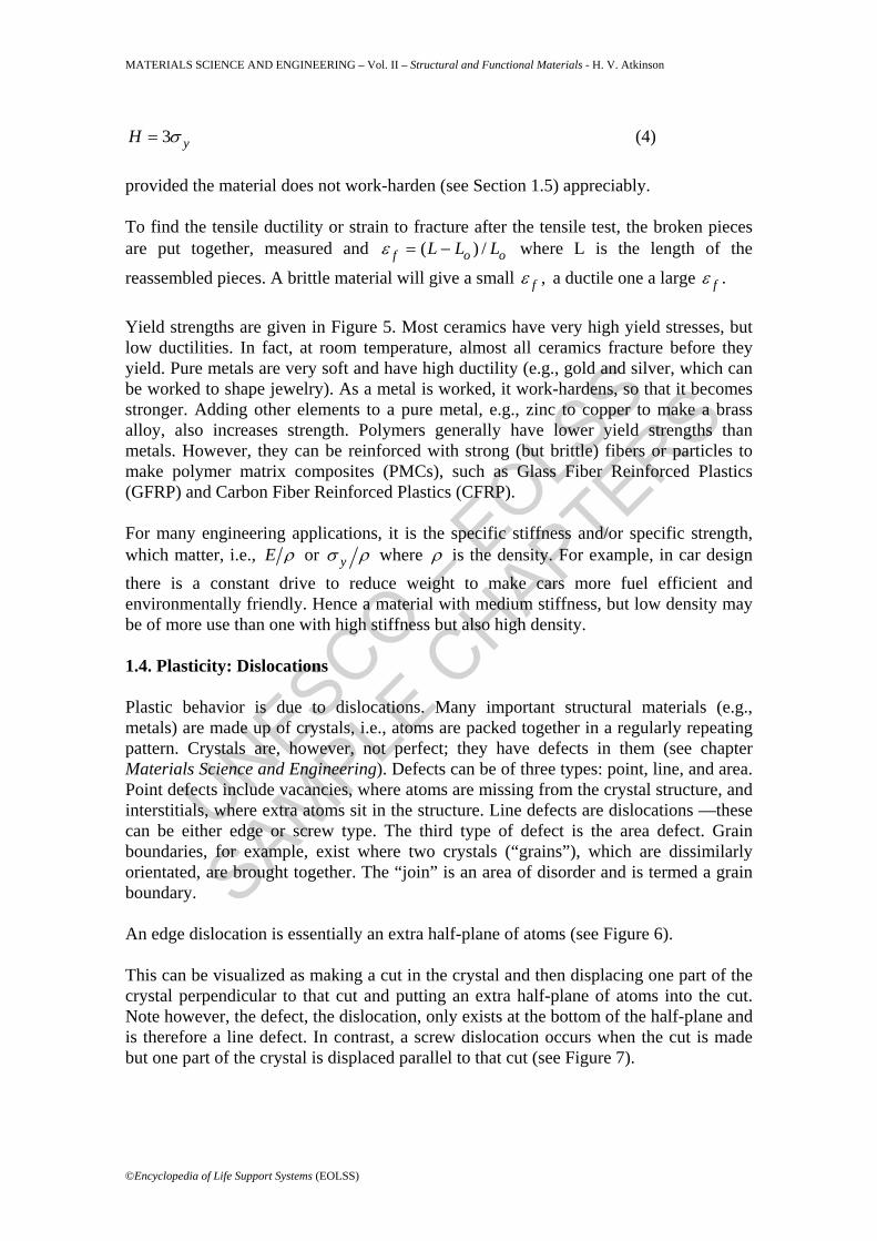
3 yH σ= (4) provided the material does not work-harden (see Section 1.5) appreciably. To find the tensile ductility or strain to fracture after the tensile test, the broken pieces are put together, measured and ( ) /f o oL L Lε = − where L is the length of the
reassembled pieces. A brittle material will give a small ,fε a ductile one a large .fε Yield strengths are given in Figure 5. Most ceramics have very high yield stresses, but low ductilities. In fact, at room temperature, almost all ceramics fracture before they yield. Pure metals are very soft and have high ductility (e.g., gold and silver, which can be worked to shape jewelry). As a metal is worked, it work-hardens, so that it becomes stronger. Adding other elements to a pure metal, e.g., zinc to copper to make a brass alloy, also increases strength. Polymers generally have lower yield strengths than metals. However, they can be reinforced with strong (but brittle) fibers or particles to make polymer matrix composites (PMCs), such as Glass Fiber Reinforced Plastics (GFRP) and Carbon Fiber Reinforced Plastics (CFRP). For many engineering applications, it is the specific stiffness and/or specific strength, which matter, i.e., E ρ or yσ ρ where ρ is the density. For example, in car design there is a constant drive to reduce weight to make cars more fuel efficient and environmentally friendly. Hence a material with medium stiffness, but low density may be of more use than one with high stiffness but also high density. 1.4. Plasticity: Dislocations Plastic behavior is due to dislocations. Many important structural materials (e.g., metals) are made up of crystals, i.e., atoms are packed together in a regularly repeating pattern. Crystals are, however, not perfect; they have defects in them (see chapter Materials Science and Engineering). Defects can be of three types: point, line, and area. Point defects include vacancies, where atoms are missing from the crystal structure, and interstitials, where extra atoms sit in the structure. Line defects are dislocations —these can be either edge or screw type. The third type of defect is the area defect. Grain boundaries, for example, exist where two crystals (“grains”), which are dissimilarly orientated, are brought together. The “join” is an area of disorder and is termed a grain boundary. An edge dislocation is essentially an extra half-plane of atoms (see Figure 6). This can be visualized as making a cut in the crystal and then displacing one part of the crystal perpendicular to that cut and putting an extra half-plane of atoms into the cut. Note however, the defect, the dislocation, only exists at the bottom of the half-plane and is therefore a line defect. In contrast, a screw dislocation occurs when the cut is made but one part of the crystal is displaced parallel to that cut (see Figure 7).

UNESCO – EOLS
S
SAMPLE C
HAPTERS
MATERIALS SCIENCE AND ENGINEERING – Vol. II – Structural and Functional Materials - H. V. Atkinson
©Encyclopedia of Life Support Systems (EOLSS)
Figure 6. Edge Dislocation
Figure 7. Screw Dislocation Again the dislocation is a line. Plasticity occurs because of dislocations. As a material is loaded, initially the behavior is elastic, simply due to the stretching of the bonds between atoms and those bonds returning to their original length when the original load is removed. However, there comes a point, the yield point, where dislocations start to move in response to the stress.

UNESCO – EOLS
S
SAMPLE C
HAPTERS
MATERIALS SCIENCE AND ENGINEERING – Vol. II – Structural and Functional Materials - H. V. Atkinson
©Encyclopedia of Life Support Systems (EOLSS)
Imagine an edge dislocation. This is equivalent to a carpet ruck. It is much easier to move a carpet across a floor by kicking a ruck across it from one side to the other (Figure 8) than by pulling (or pushing) the whole carpet bodily across the floor in one go.
Figure 8. The “Carpet Ruck” Analogy of a Dislocation So one part of the crystal moves relative to the other in response to the stress by the edge dislocation moving along the glide plane, not by the whole half crystal moving relative to the other half crystal in one “go.” Physically, the dislocation is moving by the bonds along the dislocation line shifting from one side to the other. Dislocations cannot only glide, but also climb from one glide plane to another. For example, for the edge dislocation in Figure 6 to climb from glide plane 1 to glide plane 2, a whole line of atoms must diffuse away from the bottom of the half-plane. This takes time. Glide, in contrast, is almost instantaneous. 1.5. Work-hardening, Recovery and Recrystallization When crystals yield, dislocations move through them along the glide planes. Dislocations in intersecting glide planes interact and obstruct one another, causing work-hardening, i.e., the steeply rising stress-strain curve after yield in Figure 4. This accumulation of dislocations leads to a rise in the energy stored in the material and a driving force for the energy to be reduced. If the material is heated up this can occur through the processes of recovery and recrystallization. In recovery, dislocations move out of their slip planes by climb and screw dislocations move from one glide plane to another to avoid obstacles. There is some dislocation rearrangement so that energy is reduced, e.g., edge dislocations stack one above another in what are called “cell walls.” With further heating, the more drastic process of recrystallization occurs with grain

UNESCO – EOLS
S
SAMPLE C
HAPTERS
MATERIALS SCIENCE AND ENGINEERING – Vol. II – Structural and Functional Materials - H. V. Atkinson
©Encyclopedia of Life Support Systems (EOLSS)
boundaries sweeping through the material, replacing the work-hardened structure of tangled up dislocations with a new set of more perfect grains, giving complete softening. 1.6. Fracture Toughness Once a crack is present in a structure, fracture toughness indicates how resistant the material is to the growth of that crack. Sometimes strength and toughness are confused but they are quite distinct properties. A material can be strong but also very brittle, as exemplified by glass.
Figure 9. Values of (a) Toughness Gc (b) Fracture Toughness Kc. Values at room temperature unless starred (Source: Ashby M. F. and Jones D. R. H. (1980).
Engineering Materials 1: An Introduction to their Properties and Applications, Pergamon)
Engineers must design against fast fracture, otherwise spectacular accidents can happen: sudden collapse of bridges, welded ships breaking in two, explosions of large pressure vessels. The resistance to crack growth is measured by Gc, the toughness, and Kc, the fracture toughness. Gc is the energy absorbed in making unit area of crack (surfaces have an energy per area, which must be supplied if fresh surface is to be exposed). A high toughness means that it is hard to make a crack propagate; e.g., copper has a
6 2~ 10cG Jm− , whereas in contrast, glass is brittle and has a Gc of only 10 Jm–2. The
fracture toughness c cK EG= 3/ 2( )MNm− . Fast fracture occurs when aσ π >Kc
where “a” is the length of the crack. aσ π is called the stress intensity factor. It

UNESCO – EOLS
S
SAMPLE C
HAPTERS
MATERIALS SCIENCE AND ENGINEERING – Vol. II – Structural and Functional Materials - H. V. Atkinson
©Encyclopedia of Life Support Systems (EOLSS)
depends on both the stress σ and the length of the crack “a,” and so fast fracture will occur when either the crack reaches a critical size or when the stress reaches a critical level. Toughness and fracture toughness values are given in Figure 9, and it can be seen that ice and ceramics are very brittle, whereas pure metals are tough. Polymers have intermediate toughness Gc but low fracture toughness Kc (because their moduli are low). However, if a polymer is reinforced with particles or fibers, then the fracture toughness can be much improved, as the reinforcing phase interferes with crack propagation. Most metals are tough at, or above, room temperature but, as the temperature is reduced, the metals, which have crystal structures, and which are body centered cubic (e.g., steels) or hexagonal close packed (e.g., zinc), become brittle. - - -
TO ACCESS ALL THE 48 PAGES OF THIS CHAPTER, Visit: http://www.eolss.net/Eolss-sampleAllChapter.aspx
Bibliography Anderson J. C., Leaver K. D., Rawlings R. D., and Alexander J. M. (1990). Materials Science, 4th edition, Stanley Thornes. [General undergraduate level textbook.]
Ashby M. F. and Jones D. R. H. (1980). Engineering Materials 1: An Introduction to their Properties and Applications, Vol. 1, 278 pp. and Vol. 2, 379 pp. Oxford: Pergamon. [General undergraduate level textbook written for engineering students with no previous background in materials science.]
Ashby M. F. and Jones D. R. H. (1996). Engineering Materials 1: An Introduction to their Properties and Applications, 2nd edition. 306 pp. Oxford: Butterworth. [General undergraduate level textbook written for engineering students with no previous background in materials science.]
Callister W. D., Jr. (2001). Fundamentals of Materials Science and Engineering/An Interactive e.Text, 871 pp. New York/Chichester: John Wiley. [General undergraduate level textbook.]
Cottrell A. (1975). An Introduction to Metallurgy, 548 pp. London: Edward Arnold. [General undergraduate level textbook.]
Gordon J. E. (1991). The New Science of Strong Materials: or Why You Don’t Fall Through the Floor, 2nd edition, 287 pp. Harmondsworth: Penguin. [Readable book for members of the general public.]
Jiles D. (1994). Introduction to the Electronic Properties of Materials, 372 pp. London: Chapman and Hall. [Undergraduate level textbook.]
Solymar L. (1998). Lectures on the Electrical Properties of Materials, 6th edition (eds. L. Solymar and D. Walsh), 465 pp. Oxford: Oxford University Press. [Undergraduate level textbook.] Biographical Sketch

UNESCO – EOLS
S
SAMPLE C
HAPTERS
MATERIALS SCIENCE AND ENGINEERING – Vol. II – Structural and Functional Materials - H. V. Atkinson
©Encyclopedia of Life Support Systems (EOLSS)
Dr Helen Atkinson is a Reader in the Department of Engineering Materials at Sheffield University. She has a first class degree in Metallurgy and Materials Science from Cambridge University and a Ph.D. from Imperial College of Science and Technology. She is a Fellow of the Institute of Materials and a Chartered Engineer. Her research group is working on the innovative manufacturing route called thixoforming, which involves processing metallic alloys in the semi-solid state. Other research interests include: inclusions in clean steels; grain growth and hot isostatic pressing. Dr Atkinson has collaborated widely with industry running interdisciplinary projects with both statistics and mechanical engineering. She has published over 90 papers and is a member of the Editorial Board of “Fatigue and Fracture of Engineering Materials and Structures.”
Dr Atkinson has served on: the UK Government’s Technology Foresight Materials Panel identifying priorities for materials R&D in the UK (1994–1999); Chemicals and Materials Task Force of the UK Government’s Foresight Crime Prevention Panel (1999–2000); UK Government Office of Science and Technology Action Group on Sensors (1997–1998); Engineering and Physical Sciences Research Council (EPSRC) research project prioritization panels (1995–present) and materials program evaluation panels (1998, 1999, 2000); a Flanders government research project prioritization panel (1999); Institute of Metals Council (1989–1991); Institute of Materials Council (1992–1996); panels assessing materials teaching in universities for the Higher Education Funding Council for England (1996–1999). Within the University of Sheffield, she is a member of the University Research Committee (2000–present) and the Graduate Research Development Committee (2000–present).