Structural Analysis: Space Truss
22
Structural Analysis: Space Truss Space Truss - 6 bars joined at their ends to form the edges of a tetrahedron as the basic non-collapsible unit - 3 additional concurrent bars whose ends are attached to three joints on the existing structure are required to add a new rigid unit to extend the structure. If center lines of joined members intersect at a point Two force members assumption is justified Each member under Compression or Tension A space truss formed in this way is called a Simple Space Truss 1 ME101 - Division III Kaustubh Dasgupta
-
Upload
trinhkhanh -
Category
Documents
-
view
251 -
download
13
Transcript of Structural Analysis: Space Truss
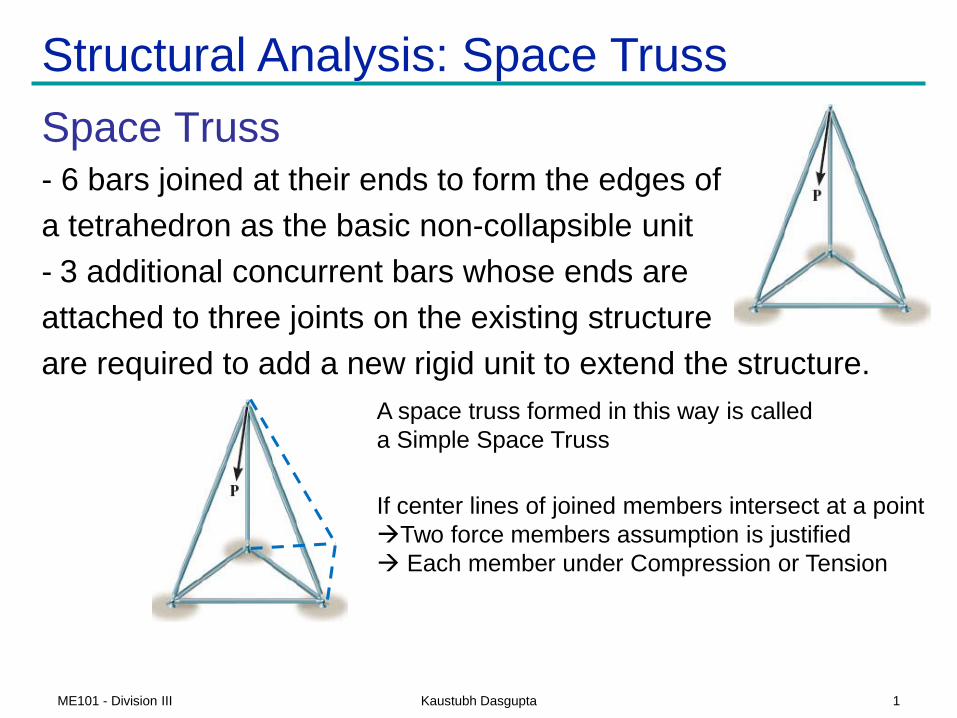
Structural Analysis: Space Truss
Space Truss- 6 bars joined at their ends to form the edges of
a tetrahedron as the basic non-collapsible unit
- 3 additional concurrent bars whose ends are
attached to three joints on the existing structure
are required to add a new rigid unit to extend the structure.
If center lines of joined members intersect at a point
Two force members assumption is justified
Each member under Compression or Tension
A space truss formed in this way is called
a Simple Space Truss
1ME101 - Division III Kaustubh Dasgupta

Space Truss Analysis: Method of Joints
• Method of Joints
– All the member forces are required
– Scalar equation (force) at each joint
• Fx = 0, Fy = 0, Fz = 0
– Solution of simultaneous equations
2ME101 - Division III Kaustubh Dasgupta
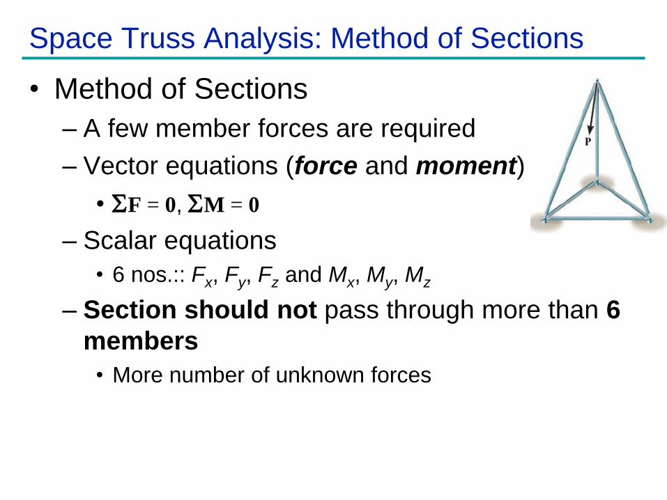
Space Truss Analysis: Method of Sections
• Method of Sections
– A few member forces are required
– Vector equations (force and moment)
• F = 0, M = 0
– Scalar equations
• 6 nos.:: Fx, Fy, Fz and Mx, My, Mz
– Section should not pass through more than 6
members
• More number of unknown forces
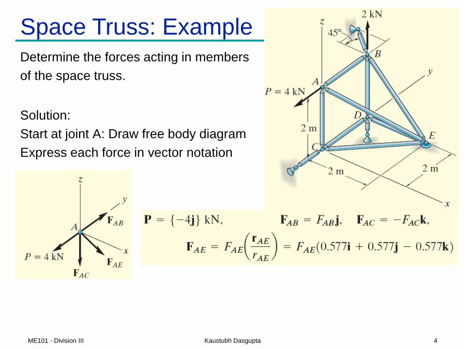
Space Truss: ExampleDetermine the forces acting in members
of the space truss.
Solution:
Start at joint A: Draw free body diagram
Express each force in vector notation
4ME101 - Division III Kaustubh Dasgupta
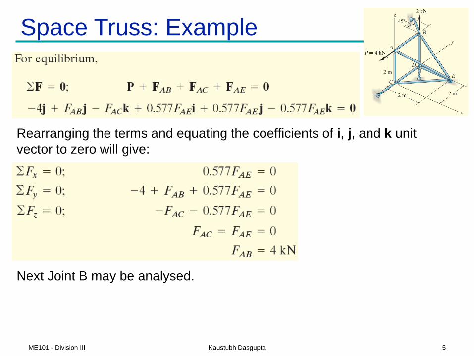
Space Truss: Example
Rearranging the terms and equating the coefficients of i, j, and k unit
vector to zero will give:
Next Joint B may be analysed.
5ME101 - Division III Kaustubh Dasgupta
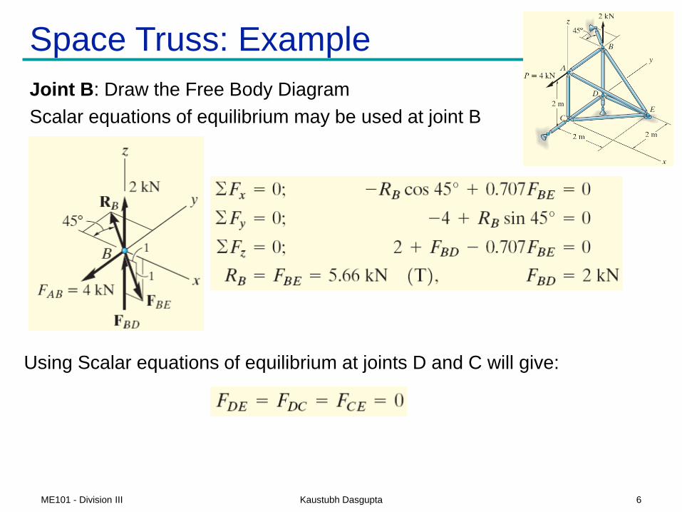
Space Truss: Example
Using Scalar equations of equilibrium at joints D and C will give:
Joint B: Draw the Free Body Diagram
Scalar equations of equilibrium may be used at joint B
6ME101 - Division III Kaustubh Dasgupta

Recapitulation :: Support Reaction
7ME101 - Division III Kaustubh Dasgupta
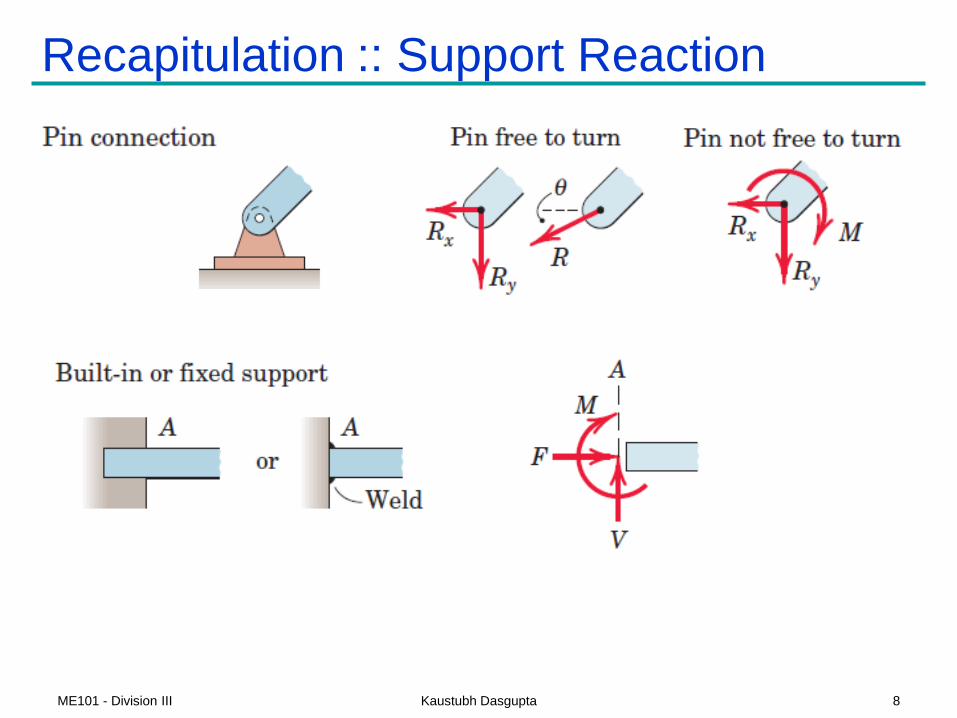
Recapitulation :: Support Reaction
8ME101 - Division III Kaustubh Dasgupta

Recapitulation :: Free Body Diagram
9ME101 - Division III Kaustubh Dasgupta
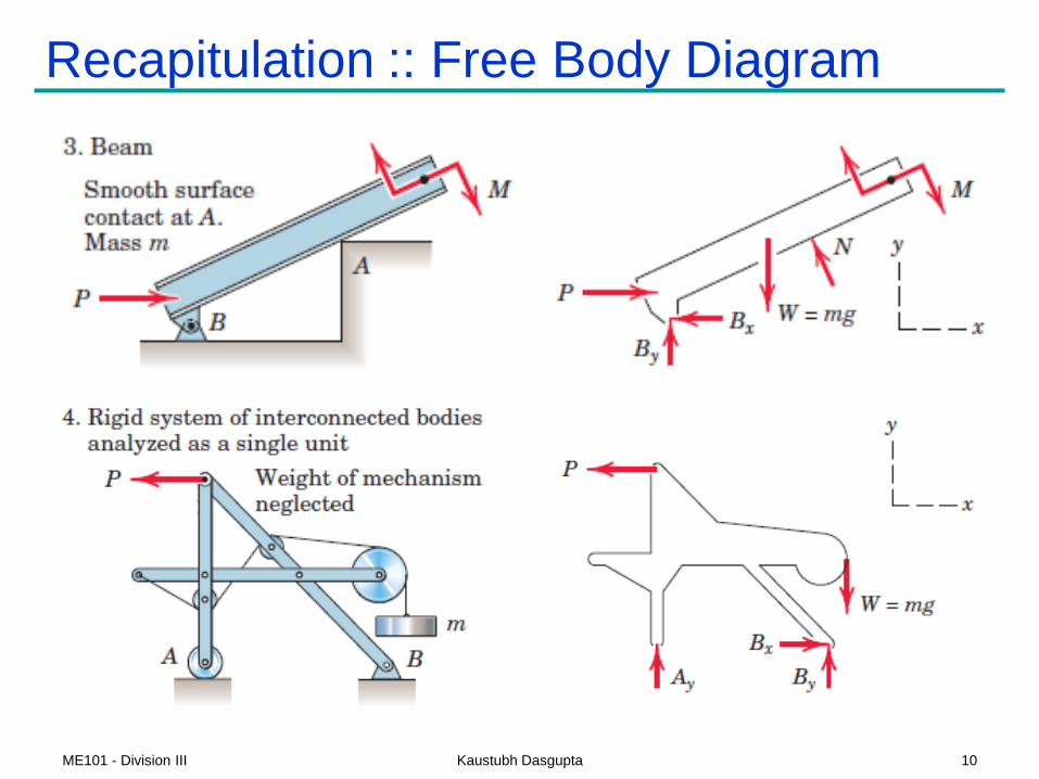
Recapitulation :: Free Body Diagram
10ME101 - Division III Kaustubh Dasgupta
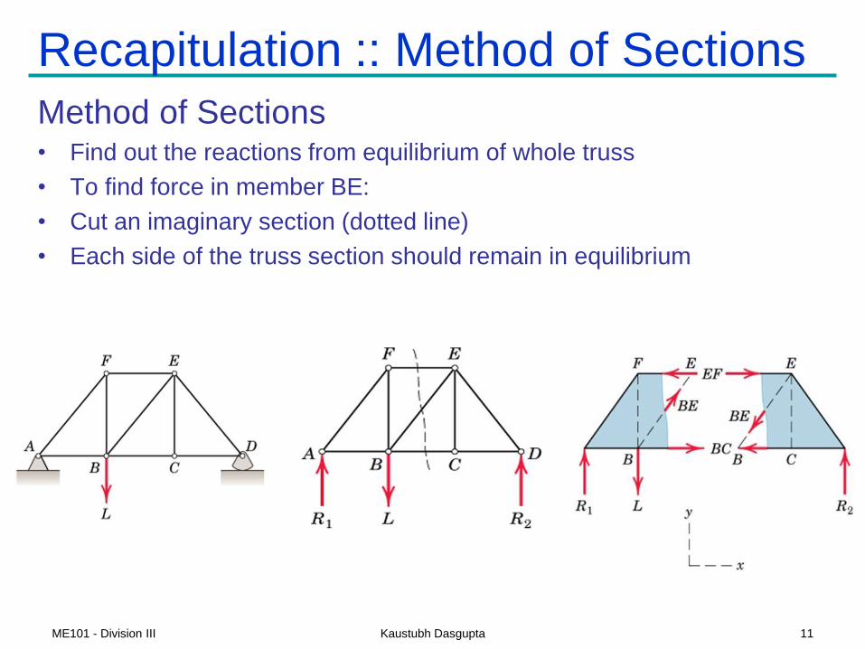
Recapitulation :: Method of Sections
Method of Sections• Find out the reactions from equilibrium of whole truss
• To find force in member BE:
• Cut an imaginary section (dotted line)
• Each side of the truss section should remain in equilibrium
11ME101 - Division III Kaustubh Dasgupta

• Calculate the force in member DJ
Example: Method of Sections
12ME101 - Division III Kaustubh Dasgupta
Direction of JK :: Moment @ C
Direction of CJ :: Moment @ A

Example: Method of Sections
13ME101 - Division III Kaustubh Dasgupta

Frames and Machines
A structure is called a Frame or Machine
if at least one of its individual members
is a multi-force member
• member with 3 or more forces acting on it, or
• member with 2 or more forces and
1 or more couple acting
Frames: generally stationary and are used to support loads
Machines: contain moving parts and are designed to transmit
and alter the effect of forces acting
Multi-force members: the forces in these members in general
will not be along the directions of the members
methods used in simple truss analysis cannot be used
14ME101 - Division III Kaustubh Dasgupta

Frames and Machines
Interconnected Rigid Bodies with Multi-force Members
• Rigid Non-collapsible–structure constitutes a rigid unit by itself
when removed from its supports
–first find all forces external to the structure treated as a single rigid body
–then dismember the structure & consider equilibrium of each part
•Non-rigid Collapsible–structure is not a rigid unit by itself but depends on its external supports
for rigidity
–calculation of external support reactions
cannot be completed until the structure is
dismembered and individual parts are
analysed.
15ME101 - Division III Kaustubh Dasgupta

Frames and Machines
Free Body Diagrams: Forces of Interactions• force components must be consistently represented in
opposite directions on the separate FBDs (Ex: Pin at A).
• apply action-and-reaction principle (Ex: Ball & Socket at A).
• Vector notation: use plus sign for an action and a minus sign
for the corresponding reaction
Pin Connection at A Ball & Socket at A
16ME101 - Division III Kaustubh Dasgupta
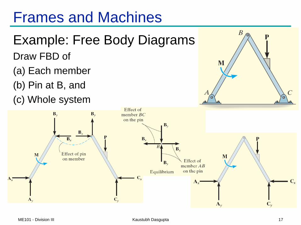
Frames and Machines
Example: Free Body DiagramsDraw FBD of
(a) Each member
(b) Pin at B, and
(c) Whole system
17ME101 - Division III Kaustubh Dasgupta

Example on Frames and Machines
Compute the horizontal and vertical components of all forces
acting on each of the members (neglect self weight)
18ME101 - Division III Kaustubh Dasgupta

Frames and Machines
Example Solution:
3 supporting members form a
rigid non-collapsible assembly
Frame Statically Determinate Externally
Draw FBD of the entire frame
3 Equilibrium equations are available
Pay attention to sense of Reactions
19ME101 - Division III Kaustubh Dasgupta

Frames and Machines
Example Solution: Dismember the frame
and draw separate FBDs of each member
- show loads and reactions on each member
due to connecting members (interaction forces)
Begin with FBD of Pulley
Ax=4.32 kN
Ay=3.92 kN
D=4.32 kN
Then draw FBD of Members BF, CE, and AD
20ME101 - Division III Kaustubh Dasgupta

Frames and Machines
Example Solution:
FBDs
Ax=4.32 kN
Ay=3.92 kN
D=4.32 kN
CE is a two-force member
Direction of the line joining the two points
of force application determines the direction
of the forces acting on a two-force member.
Shape of the member is not important.
21ME101 - Division III Kaustubh Dasgupta

Frames and Machines
Example Solution:
Find unknown forces from equilibrium
Member BF
Member CE
[∑Fx = 0] Cx = Ex = 13.08 kN
Checks:
22ME101 - Division III Kaustubh Dasgupta