Stress Analysis of Pelton Bucket Using Mechanical APDL€¦ · using Mechanical APDL. The geometric...
6
Asian Journal of Engineering and Applied Technology ISSN: 2249-068X Vol. 4 No. 1, 2015, pp.24-29 © The Research Publication, www.trp.org.in Stress Analysis of Pelton Bucket Using Mechanical APDL Sonendra 1 , Naman Agarwal 2 and T.S.Deshmuk 3 1&2 Mechanical Department, ITS Engineering College, Gr. Noida, Uttar Pradesh, India 3 Civil Department, MANIT Bhopal, Madhya Pradesh (India) E-mail: [email protected], [email protected], [email protected] Abstract - In the present work an attempt has been made to analyse the stress developed on the surface of Pelton bucket using Mechanical APDL. The geometric modelling of this bucket has been done using CATIA software for a 50 m head and stress analysis has been done in Mechanical APDL. The stress analysis has been done considering bucket as a cantilever element fixed to the disc at one end with the force of jet applied at the splitter. The stress analysis has been done for flow rates ranging from 100 lit/sec to 150 lit/sec and speed ranging from 700 rpm to 900 rpm. It is observed that 1 st principle stress is higher than 2 nd principle stress and 3 rd principle stress. Von Mises stress as well as all three principle stresses decreases as rotational speed of pelton wheel increases. I. INTRODUCTION The Pelton turbine is a hydraulic prime mover which generates power by first converting the pressure energy of water into kinetic energy with the help of jet nozzle assembly and then mechanical power is developed from this kinetic energy with the use of runner. Runner of Pelton turbine is made of buckets which are mounted on the periphery of a disc.The bucket of Pelton turbine has very complex geometry. The kinetic energy of a jet of water is converted into angular rotation of the bucket as the jet strikes. The high-velocity jet of water emerging from a nozzle impinges on the bucket and sets the wheel into motion.Pelton turbine is tangential flow impulse turbine.APelton turbine consists of a series of buckets mounted around the periphery of a circular disc. II. GEOMETRIC MODELLING The geometric modelling of the given pelton bucket has been done using CATIA software. In the present work, the runner of a Pelton turbine model for 50 m head has been used for stress analysis. The modelling of the runner blade surface was done with the help of profile coordinates at various sections. The coordinates were available for 6 sections(A-A, B-B, C-C, D-D, E-E, F-F) along the length of the blade and 5 sections (U-U, W-W, S-S, K-K, R-R) along the width of the blade. In addition to this, the coordinates of the plan view as well as lip surface were also available. Initially the curves for all the 11 sections were plotted (in different planes) with the distances between the adjacent sections being determined on the basis of plan view. Distance between splitter and E-E curve, E-E curve and A-A curve, A-A curve and F-F curve, F-F curve and B-B curve is 4.15 mm. Distance between splitter and C-C curve is 28.07mm. Fig.1 Profile of Pelton Bucket Distance between splitter and DD curve is 37.49 mm. Section U-U passes through origin. Distance between U-U curve and W-W curve is 20.87mm. Distance between UU curve and SS curve is 23 mm. Distance between W-W and K-K curve 11.45 mm. Distance between R-R and S-S curve is 11.45 mm. The width of the bucket is 104.5 mm. Using the given co-ordinates, curves were created using point and spline commands. The final assembly of all the bucket curves for 11 sections is shown below. 24 AJEAT Vol. 4 No. 1, Jan - June 2015
Transcript of Stress Analysis of Pelton Bucket Using Mechanical APDL€¦ · using Mechanical APDL. The geometric...
Asian Journal of Engineering and Applied Technology ISSN: 2249-068X Vol. 4 No. 1, 2015, pp.24-29
© The Research Publication, www.trp.org.in
Stress Analysis of Pelton Bucket Using Mechanical APDL
Sonendra1, Naman Agarwal2 and T.S.Deshmuk3
1&2Mechanical Department, ITS Engineering College, Gr. Noida, Uttar Pradesh, India 3Civil Department, MANIT Bhopal, Madhya Pradesh (India)
E-mail: [email protected], [email protected], [email protected]
Abstract - In the present work an attempt has been made to analyse the stress developed on the surface of Pelton bucket using Mechanical APDL. The geometric modelling of this bucket has been done using CATIA software for a 50 m head and stress analysis has been done in Mechanical APDL. The stress analysis has been done considering bucket as a cantilever element fixed to the disc at one end with the force of jet applied at the splitter. The stress analysis has been done for flow rates ranging from 100 lit/sec to 150 lit/sec and speed ranging from 700 rpm to 900 rpm. It is observed that 1st principle stress is higher than 2nd principle stress and 3rd principle stress. Von Mises stress as well as all three principle stresses decreases as rotational speed of pelton wheel increases.
I. INTRODUCTION
The Pelton turbine is a hydraulic prime mover which generates power by first converting the pressure energy of water into kinetic energy with the help of jet nozzle assembly and then mechanical power is developed from this kinetic energy with the use of runner. Runner of Pelton turbine is made of buckets which are mounted on the periphery of a disc.The bucket of Pelton turbine has very complex geometry. The kinetic energy of a jet of water is converted into angular rotation of the bucket as the jet strikes. The high-velocity jet of water emerging from a nozzle impinges on the bucket and sets the wheel into
motion.Pelton turbine is tangential flow impulse turbine.APelton turbine consists of a series of buckets mounted around the periphery of a circular disc.
II. GEOMETRIC MODELLING The geometric modelling of the given pelton bucket has been done using CATIA software. In the present work, the runner of a Pelton turbine model for 50 m head has been used for stress analysis. The modelling of the runner blade surface was done with the help of profile coordinates at various sections. The coordinates were available for 6 sections(A-A, B-B, C-C, D-D, E-E, F-F) along the length of the blade and 5 sections (U-U, W-W, S-S, K-K, R-R) along the width of the blade. In addition to this, the coordinates of the plan view as well as lip surface were also available. Initially the curves for all the 11 sections were plotted (in different planes) with the distances between the adjacent sections being determined on the basis of plan view. Distance between splitter and E-E curve, E-E curve and A-A curve, A-A curve and F-F curve, F-F curve and B-B curve is 4.15 mm. Distance between splitter and C-C curve is 28.07mm.
Fig.1 Profile of Pelton Bucket
Distance between splitter and DD curve is 37.49 mm. Section U-U passes through origin. Distance between U-U curve and W-W curve is 20.87mm. Distance between UU curve and SS curve is 23 mm. Distance between W-W and K-K curve 11.45 mm. Distance between R-R and S-S curve
is 11.45 mm. The width of the bucket is 104.5 mm. Using the given co-ordinates, curves were created using point and spline commands. The final assembly of all the bucket curves for 11 sections is shown below.
24AJEAT Vol. 4 No. 1, Jan - June 2015
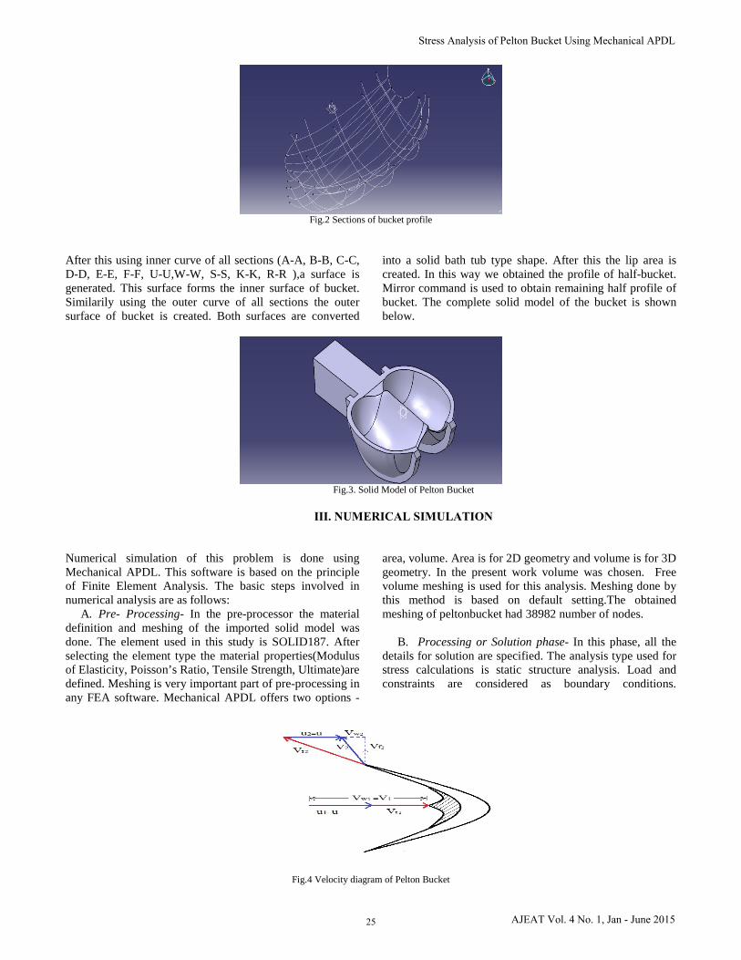
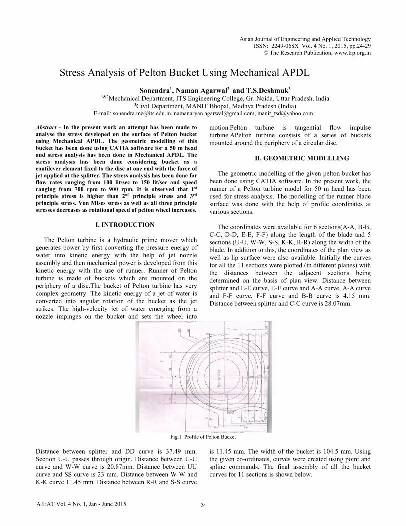
Fig.2 Sections of bucket profile
After this using inner curve of all sections (A-A, B-B, C-C, D-D, E-E, F-F, U-U,W-W, S-S, K-K, R-R ),a surface isgenerated. This surface forms the inner surface of bucket.Similarily using the outer curve of all sections the outersurface of bucket is created. Both surfaces are converted
into a solid bath tub type shape. After this the lip area is created. In this way we obtained the profile of half-bucket. Mirror command is used to obtain remaining half profile of bucket. The complete solid model of the bucket is shown below.
Fig.3. Solid Model of Pelton Bucket
III. NUMERICAL SIMULATION
Numerical simulation of this problem is done using Mechanical APDL. This software is based on the principle of Finite Element Analysis. The basic steps involved in numerical analysis are as follows:
A. Pre- Processing- In the pre-processor the materialdefinition and meshing of the imported solid model was done. The element used in this study is SOLID187. After selecting the element type the material properties(Modulus of Elasticity, Poisson’s Ratio, Tensile Strength, Ultimate)are defined. Meshing is very important part of pre-processing in any FEA software. Mechanical APDL offers two options -
area, volume. Area is for 2D geometry and volume is for 3D geometry. In the present work volume was chosen. Free volume meshing is used for this analysis. Meshing done by this method is based on default setting.The obtained meshing of peltonbucket had 38982 number of nodes.
B. Processing or Solution phase- In this phase, all thedetails for solution are specified. The analysis type used for stress calculations is static structure analysis. Load and constraints are considered as boundary conditions.
Fig.4 Velocity diagram of Pelton Bucket
25
Stress Analysis of Pelton Bucket Using Mechanical APDL
AJEAT Vol. 4 No. 1, Jan - June 2015
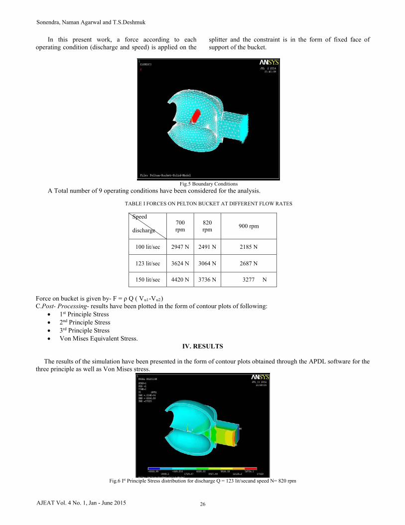
In this present work, a force according to each operating condition (discharge and speed) is applied on the
splitter and the constraint is in the form of fixed face of support of the bucket.
Fig.5 Boundary Conditions
A Total number of 9 operating conditions have been considered for the analysis.
TABLE I FORCES ON PELTON BUCKET AT DIFFERENT FLOW RATES
Speed
discharge 700 rpm
820 rpm 900 rpm
100 lit/sec 2947 N 2491 N 2185 N
123 lit/sec 3624 N 3064 N 2687 N
150 lit/sec 4420 N 3736 N 3277 N
Force on bucket is given by- F = ρ Q ( Vu1-Vu2) C.Post- Processing- results have been plotted in the form of contour plots of following:
• 1st Principle Stress • 2nd Principle Stress • 3rd Principle Stress • Von Mises Equivalent Stress.
IV. RESULTS
The results of the simulation have been presented in the form of contour plots obtained through the APDL software for the three principle as well as Von Mises stress.
Fig.6 Ist Principle Stress distribution for discharge Q = 123 lit/secand speed N= 820 rpm
26
Sonendra, Naman Agarwal and T.S.Deshmuk
AJEAT Vol. 4 No. 1, Jan - June 2015
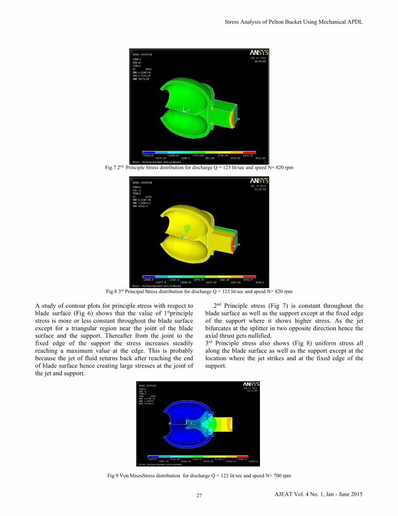
Fig.7 2nd Principle Stress distribution for discharge Q = 123 lit/sec and speed N= 820 rpm
Fig.8 3rd Principal Stress distribution for discharge Q = 123 lit/sec and speed N= 820 rpm
A study of contour plots for principle stress with respect to blade surface (Fig 6) shows that the value of 1stprinciple stress is more or less constant throughout the blade surface except for a triangular region near the joint of the blade surface and the support. Thereafter from the joint to the fixed edge of the support the stress increases steadily reaching a maximum value at the edge. This is probably because the jet of fluid returns back after reaching the end of blade surface hence creating large stresses at the joint of the jet and support.
2nd Principle stress (Fig 7) is constant throughout the blade surface as well as the support except at the fixed edge of the support where it shows higher stress. As the jet bifurcates at the splitter in two opposite direction hence the axial thrust gets nullified. 3rd Principle stress also shows (Fig 8) uniform stress all along the blade surface as well as the support except at the location where the jet strikes and at the fixed edge of the support.
Fig 9 Von MisesStress distribution for discharge Q = 123 lit/sec and speed N= 700 rpm
27
Stress Analysis of Pelton Bucket Using Mechanical APDL
AJEAT Vol. 4 No. 1, Jan - June 2015
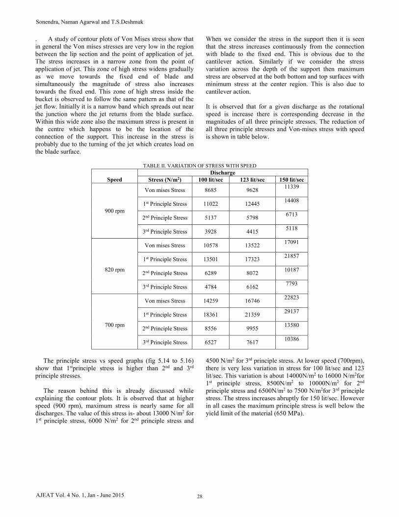
. A study of contour plots of Von Mises stress show that in general the Von mises stresses are very low in the region between the lip section and the point of application of jet. The stress increases in a narrow zone from the point of application of jet. This zone of high stress widens gradually as we move towards the fixed end of blade and simultaneously the magnitude of stress also increases towards the fixed end. This zone of high stress inside the bucket is observed to follow the same pattern as that of the jet flow. Initially it is a narrow band which spreads out near the junction where the jet returns from the blade surface. Within this wide zone also the maximum stress is present in the centre which happens to be the location of the connection of the support. This increase in the stress is probably due to the turning of the jet which creates load on the blade surface.
When we consider the stress in the support then it is seen that the stress increases continuously from the connection with blade to the fixed end. This is obvious due to the cantilever action. Similarly if we consider the stress variation across the depth of the support then maximum stress are observed at the both bottom and top surfaces with minimum stress at the center region. This is also due to cantilever action. It is observed that for a given discharge as the rotational speed is increase there is corresponding decrease in the magnitudes of all three principle stresses. The reduction of all three principle stresses and Von-mises stress with speed is shown in table below.
TABLE II. VARIATION OF STRESS WITH SPEED
Speed
Discharge Stress (N/m2) 100 lit/sec 123 lit/sec 150 lit/sec
900 rpm
Von mises Stress 8685 9628 11339
1st Principle Stress 11022 12445 14408
2nd Principle Stress 5137 5798 6713
3rd Principle Stress 3928 4415 5118
820 rpm
Von mises Stress 10578 13522 17091
1st Principle Stress 13501 17323 21857
2nd Principle Stress 6289 8072 10187
3rd Principle Stress 4784 6162 7793
700 rpm
Von mises Stress 14259 16746 22823
1st Principle Stress 18361 21359 29137
2nd Principle Stress 8556 9955 13580
3rd Principle Stress 6527 7617 10386
The principle stress vs speed graphs (fig 5.14 to 5.16) show that 1stprinciple stress is higher than 2nd and 3rd principle stresses. The reason behind this is already discussed while explaining the contour plots. It is observed that at higher speed (900 rpm), maximum stress is nearly same for all discharges. The value of this stress is- about 13000 N/m2 for 1st principle stress, 6000 N/m2 for 2nd principle stress and
4500 N/m2 for 3rd principle stress. At lower speed (700rpm), there is very less variation in stress for 100 lit/sec and 123 lit/sec. This variation is about 14000N/m2 to 16000 N/m2for 1st principle stress, 8500N/m2 to 10000N/m2 for 2nd principle stress and 6500N/m2 to 7500 N/m2for 3rd principle stress. The stress increases abruptly for 150 lit/sec. However in all cases the maximum principle stress is well below the yield limit of the material (650 MPa).
28
Sonendra, Naman Agarwal and T.S.Deshmuk
AJEAT Vol. 4 No. 1, Jan - June 2015
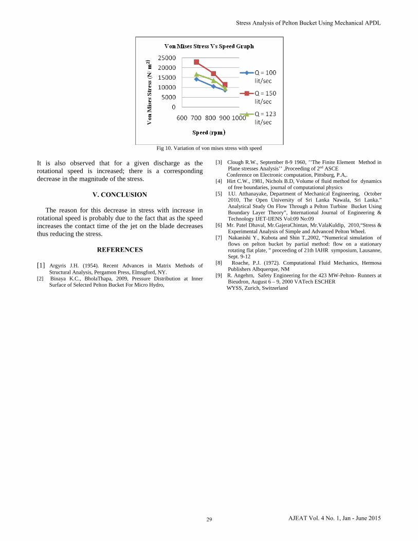
Fig 10. Variation of von mises stress with speed
It is also observed that for a given discharge as the rotational speed is increased; there is a corresponding decrease in the magnitude of the stress.
V. CONCLUSION
The reason for this decrease in stress with increase in rotational speed is probably due to the fact that as the speed increases the contact time of the jet on the blade decreases thus reducing the stress.
REFERENCES
[1] Argyris J.H. (1954). Recent Advances in Matrix Methods ofStructural Analysis, Pergamon Press, Elmsgford, NY.
[2] Binaya K.C., BholaThapa, 2009, Pressure Distribution at Inner Surface of Selected Pelton Bucket For Micro Hydro,
[3] Clough R.W., September 8-9 1960, ’’The Finite Element Method inPlane stresses Analysis’’ ,Proceeding of 2nd ASCEConference on Electronic computation, Pittsburg, P.A,.
[4] Hirt C.W., 1981, Nichols B.D, Volume of fluid method for dynamicsof free boundaries, journal of computational physics
[5] I.U. Atthanayake, Department of Mechanical Engineering, October 2010, The Open University of Sri Lanka Nawala, Sri Lanka.” Analytical Study On Flow Through a Pelton Turbine Bucket UsingBoundary Layer Theory”, International Journal of Engineering &Technology IJET-IJENS Vol:09 No:09
[6] Mr. Patel Dhaval, Mr.GajeraChintan, Mr.ValaKuldip, 2010,“Stress &Experimental Analysis of Simple and Advanced Pelton Wheel.
[7] Nakanishi Y., Kubota and Shin T.,2002, “Numerical simulation of flows on pelton bucket by partial method: flow on a stationaryrotating flat plate, ” proceeding of 21th IAHR symposium, Lausanne, Sept. 9-12
[8] Roache, P.J. (1972). Computational Fluid Mechanics, HermosaPublishers Albquerque, NM
[9] R. Angehrn, Safety Engineering for the 423 MW-Pelton- Runners atBieudron, August 6 – 9, 2000 VATech ESCHER WYSS, Zurich, Switzerland
29
Stress Analysis of Pelton Bucket Using Mechanical APDL
AJEAT Vol. 4 No. 1, Jan - June 2015