The Detection of Impact Damage to the Edges of CFRP Plates ...

Strengthening Steel Girder Bridges Strengthening Steel Girder Bridges with CFRP Plateswith CFRP Plates
T. J. Wipf B. M. PharesF. W. Klaiber Y. S. Lee
Bridge Engineering CenterIowa State University
A.H. Al-Saidy
Dept of Civil and Arch EngineeringSultan Qaboos University

Overview:Overview:Overview:Laboratory Investigation:– Evaluated the feasibility of using CFRP plates in
strengthening steel-concrete composite beams
– Tested ten small-scale, steel-concrete composite beams» Two different arrangements of CFRP and two different
levels of damage were investigated
Field Investigation:– Used CFRP plates to strengthen an existing, structurally deficient
steel girder bridge– Investigating short- and long-term effectiveness– Identified changes in structural behavior due to the addition of the
strengthening system
Advantages of CFRP:Advantages of CFRP:Advantages of CFRP:
Corrosion resistantLight weightHigh strength with a high fatigue lifeCan be installed with a minimal crew and common equipment

Nonlinear Analysis:Nonlinear Analysis:Nonlinear Analysis:
Developed and validated an analytical model to investigate the impact of the following variables:
– Area of the tension flange removed– CFRP plate ultimate strain– Area of CFRP added – CFRP stiffness– Compressive strength of deck slab concrete– Yield strength of the steel section being strengthened
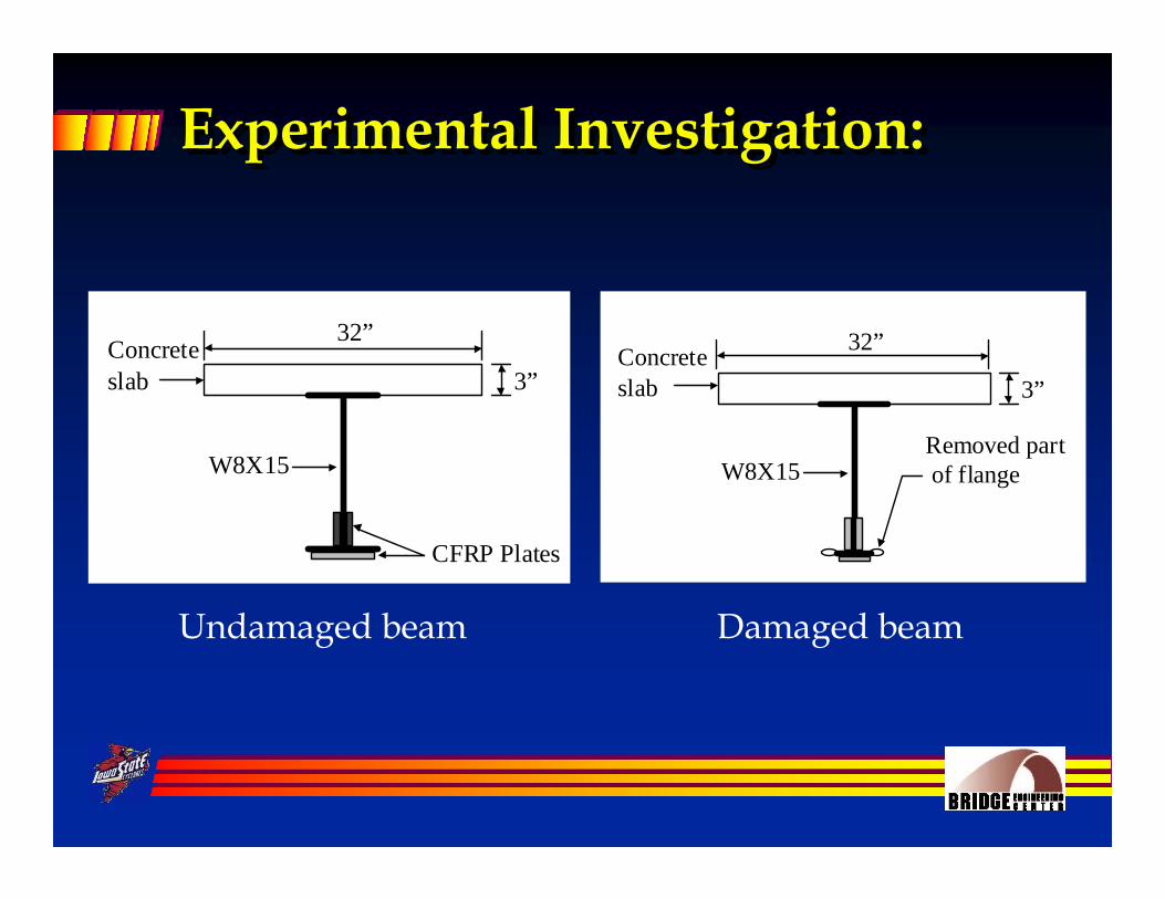
Experimental Investigation:Experimental Investigation:Experimental Investigation:
Undamaged beam
Concreteslab
32”
3”
W8X15
CFRP Plates
Concreteslab
32”
3”
W8X15Removed part of flange
Damaged beam
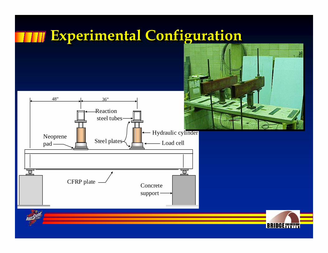
Experimental ConfigurationExperimental ConfigurationExperimental Configuration
Hydraulic cylinder
Reaction steel tubes
Load cellSteel plates
Concretesupport
CFRP plate
Neoprenepad
48” 36”

Failure ModesFailure ModesFailure Modes
CFRP plate ruptureConcrete crushing

Analytical Midspan DeflectionAnalytical Analytical MidspanMidspan DeflectionDeflection
0
5,000
10,000
15,000
20,000
25,000
30,000
35,000
0 0.5 1 1.5 2 2.5 3 3.5Deflection (in.)
Load
(lbs
) D75
D50
U

Impact of Repair Scheme 1Impact of Repair Scheme 1Impact of Repair Scheme 1
0
5,000
10,000
15,000
20,000
25,000
30,000
35,000
0 0.5 1 1.5 2 2.5 3
Deflection (in.)
Load
(lbs
) D50
U
D50R1E29

Impact of Repair Scheme 2Impact of Repair Scheme 2Impact of Repair Scheme 2
0
5,000
10,000
15,000
20,000
25,000
30,000
35,000
40,000
0 0.5 1 1.5 2 2.5 3
Deflection (in.)
Load
(lbs
)
D50
U
D50R2E29

Description of Bridge:Description of Bridge:Description of Bridge:Located in Pottawattamie County, IA on State Highway IA 92Three-span continuous steel girder bridgeRoadway width = 30 ft [ two traffic lanes ]Total length = 150 ft– Two 45.5 ft end spans and
a 59 ft center span

Description of Bridge (continued)Description of Bridge (continued)Description of Bridge (continued)
Constructed in 1938, the bridge was originally non-composite
In 1967, it was widen by adding two composite exterior girders

Strengthening SystemStrengthening SystemStrengthening System
13'-6" 13'-6"
BEAM 1 (EXTERIOR 27WF84)
LCCFRP PLATE
10'-0"
BEAM 3 (INTERIOR 27WF98)
10'-0" 12'-6"
10'-0"
20'-6"
12'-6"
BEAM 4 (INTERIOR 27WF98)
BEAM 6 (EXTERIOR 27WF84)
10'-0" 12'-6"
12'-6"
CFRP PLATE
CFRP PLATECL LC
CFRP PLATE
9" x 34 " x 12'-6" COV. P
9" x 916 " x 10'-6"
COV. PLL
F
F
E
E
F
F
G
G
20'-6"
J
J
I
I
H
H
I
I L
L
K
K
L
L
M
MCFRP PLATE

Cutting FRP Strips to the Desired LengthsCutting FRP Strips to the Desired Cutting FRP Strips to the Desired LengthsLengths

Removal of Paint from Beams – Stage 1Removal of Paint from Beams Removal of Paint from Beams –– Stage 1Stage 1

Removal of Paint from Beams – Stage 2Removal of Paint from Beams Removal of Paint from Beams –– Stage 2Stage 2
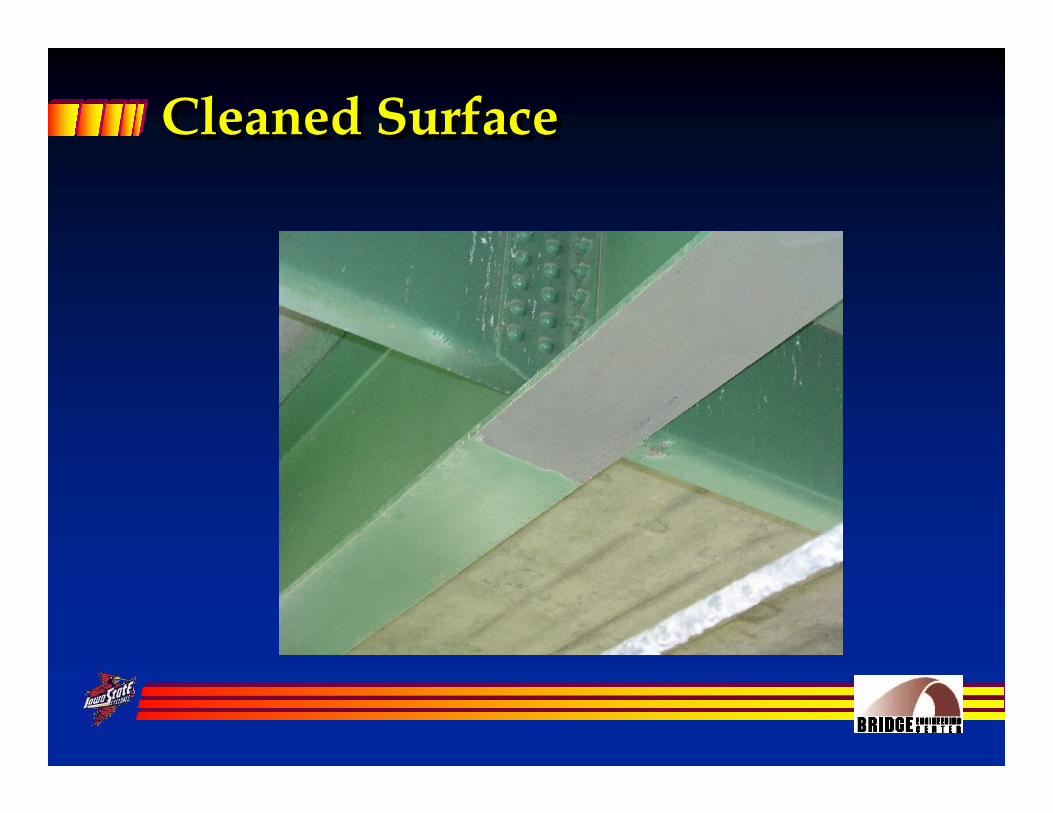
Cleaned SurfaceCleaned SurfaceCleaned Surface

Cleaning of FRP StripsCleaning of FRP StripsCleaning of FRP Strips

Field Cleaning of FRP StripsField Cleaning of FRP StripsField Cleaning of FRP Strips

Final Cleaning of Beam FlangesFinal Cleaning of Beam FlangesFinal Cleaning of Beam Flanges

Installation of FRS PrimerInstallation of FRS PrimerInstallation of FRS Primer

Application of ECS 104 Structural EpoxyApplication of ECS 104 Structural EpoxyApplication of ECS 104 Structural Epoxy

Application of ECS 104 Structural EpoxyApplication of ECS 104 Structural EpoxyApplication of ECS 104 Structural Epoxy
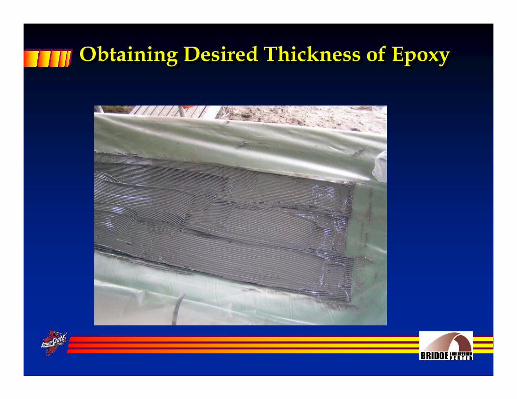
Obtaining Desired Thickness of EpoxyObtaining Desired Thickness of EpoxyObtaining Desired Thickness of Epoxy

Application of Epoxy to Beam FlangesApplication of Epoxy to Beam FlangesApplication of Epoxy to Beam Flanges

Installation of FRP Strips to End Span BeamsInstallation of FRP Strips to End Installation of FRP Strips to End Span BeamsSpan Beams

Installation of FRP Strips to End Span Beams ( continued )Installation of FRP Strips to End Installation of FRP Strips to End Span Beams ( continued )Span Beams ( continued )

Installation of FRP Strips to Center Span BeamsInstallation of FRP Strips to Center Installation of FRP Strips to Center Span BeamsSpan Beams

Installation of FRP Strips to Center Span Beams ( continued )Installation of FRP Strips to Center Installation of FRP Strips to Center Span Beams ( continued )Span Beams ( continued )
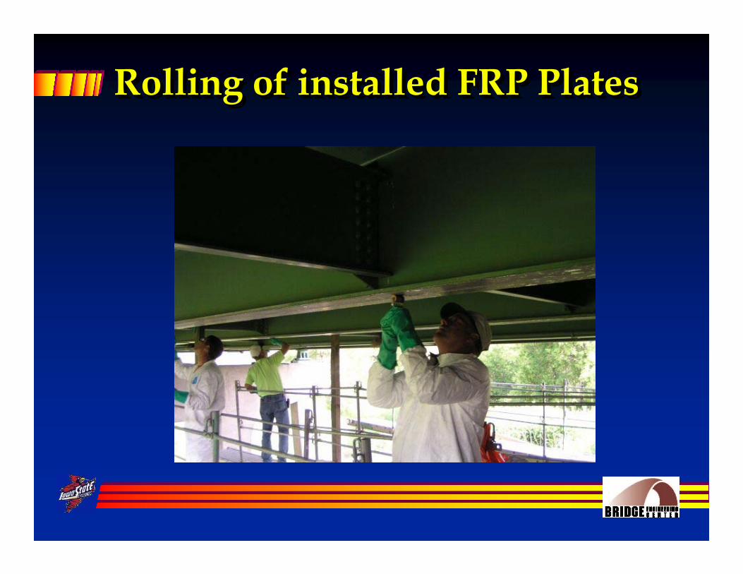
Rolling of installed FRP PlatesRolling of installed FRP PlatesRolling of installed FRP Plates

Completed Installation of FRP PlatesCompleted Installation of FRP PlatesCompleted Installation of FRP Plates
One layer (West end span) Three layers (East end span)

Load TestingLoad TestingLoad TestingHalf of bridge was instrumented 3-axle truck used in three different load paths Data collected continuously as truck crossed the bridgeInitial test and two follow-up testscompleted to date
N
4'-1.5"
4'-1.5"
8'-8"
CL3'-0"
LEGEND :
BEAM TRUCK PATH
Y3
Y2
Y1
LOADWAY
4'-0"
8'-5"
6'-9"
8'-5"
4'-0"
BEAM 1
BEAM 6
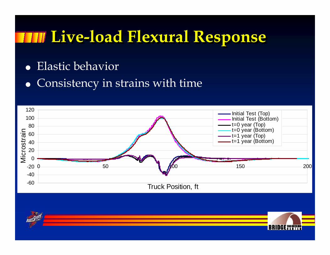
Live-load Flexural ResponseLiveLive--load Flexural Responseload Flexural ResponseElastic behaviorConsistency in strains with time
-60-40-20
020406080
100120
0 50 100 150 200
Truck Position, ft
Mic
rost
rain
Initial Test (Top)Initial Test (Bottom)t=0 year (Top)t=0 year (Bottom)t=1 year (Top)t=1 year (Bottom)

Bond PerformanceBond PerformanceBond PerformanceCritical to have adequate bond for force transferGages installed on CFRP plate to investigate the bond performanceAnalytical model developed based on strain compatibility relationExtreme fiber strains were predicted and compared with experimental data
CFRP PLATE
STRAIN GAGE
εTB
εEXT
εT
hwebhCFRP
εEXT = − εT (εT + εTB) * hCFRP
hweb

Bond PerformanceBond PerformanceBond Performance
-60-40-20
020406080
100120
0 50 100 150 200
Truck Position, ft
Mic
rost
rain
t=0 year (CFRP)t=1 year (CFRP)Analytical

Concluding Remarks….Concluding RemarksConcluding Remarks……..
Strength of damaged steel girders can be fully restored with the use of CFRP plates
Stiffness of repaired steel girders is greater than that of the damaged girder, however not fully restored to that of the undamaged girder

Concluding Remarks [continued]…Concluding Remarks [continued]Concluding Remarks [continued]……
CFRP plates have minimal impact on changing the member’s stiffness but can have a relatively large impact on changing member strength, ……if properly designed
Bond performance after one-year of service was good

Concluding Remarks [continued]….Concluding Remarks [continued]Concluding Remarks [continued]……..
The use of CFRP plates appears to be a viable strengthening alternative for steel girder bridgesHandling and installation of CFRP plates was initially relatively labor intensive and required some trainingA three-man crew was needed to install the system

Sponsorship:Sponsorship:Sponsorship:
Project was initiated by the Iowa Department of Transportation
and was funded through the Federal Highway Administration’s Innovative Bridge Research and Construction[IBRC] Program