Strengthening of prestressed viaducts by means of a...
6
Tailor Made Concrete Structures – Walraven & Stoelhorst (eds) © 2008Taylor & Francis Group, London, ISBN 978-0-415-47535-8 Strengthening of prestressed viaducts by means of a reinforced concrete overlay R.W. Keesom BAM Infraconsult, Gouda, The Netherlands W.J. Bouwmeester – van den Bos BAM Infraconsult, Gouda, The Netherlands, University of Technology, Faculty of Civil Engineering and Geosciences, Delft, The Netherlands M. van Kaam BAM Infraconsult, Gouda, The Netherlands A.Q.C. van der Horst BAM Infraconsult, Gouda, The Netherlands, University of Technology, Faculty of Civil Engineering and Geosciences, Delft, The Netherlands ABSTRACT: Many viaducts in the Netherlands have been designed for traffic loads that are smaller and less intense than required by the present day standards. This means that for maintaining the structure’s primary function, recalculation and often strengthening is required to guarantee safety and durability. For the viaducts in highway A9 near Amsterdam strengthening by a reinforced concrete overlay is used. This paper describes material testing of the existing structure, FEM-modeling of the existing and overlay structures and some aspects of the detailed design of the concrete overlay. 1 INTRODUCTION Recalculation of the structural integrity of seven viaducts in highway A9 has been conducted as part of a large-scale road renovating contract called KOS- MOS, by Rijkswaterstaat (the Dutch Public Roads and Water Works Authority), which was awarded to the combination of BAM Civil and BAM Roads. Although (visible) damage to the viaducts was neg- ligible, assessment of strength and fatigue behavior was required, due to the heavier and more intense traffic loads than anticipated during the design 35 years earlier. The philosophy of the Client was that the Contractor should either proof a surplus service life of minimum 15 years according to Dutch standards and the Rijkswaterstaat regulations (partly specifically developed for existing structures), or to strengthen the structure to enable a surplus service life of minimum 100 years. As the traffic on working days is intense, the ren- ovation and strengthening measures needed to be completed with minimum traffic disruptions. Elab- orate phasing of work was required to fulfill this requirement. For the same reason the project was executed during the summer holidays and continued 7 ∗ 24 hr during 6 weeks. BAM Infraconsult, the in-house engineering com- pany of BAM Infra, advised on material testing and in-situ testing of concrete mix and concrete strength development, conducted all required FEM- calculations and performed the detailed design for the strengthening measures. Figure 1. View of typical viaduct. 685
Transcript of Strengthening of prestressed viaducts by means of a...
Tailor Made Concrete Structures – Walraven & Stoelhorst (eds)© 2008 Taylor & Francis Group, London, ISBN 978-0-415-47535-8
Strengthening of prestressed viaducts by means ofa reinforced concrete overlay
R.W. KeesomBAM Infraconsult, Gouda, The Netherlands
W.J. Bouwmeester – van den BosBAM Infraconsult, Gouda, The Netherlands,University of Technology, Faculty of Civil Engineering and Geosciences, Delft, The Netherlands
M. van KaamBAM Infraconsult, Gouda, The Netherlands
A.Q.C. van der HorstBAM Infraconsult, Gouda, The Netherlands,University of Technology, Faculty of Civil Engineering and Geosciences, Delft, The Netherlands
ABSTRACT: Many viaducts in the Netherlands have been designed for traffic loads that are smaller and lessintense than required by the present day standards. This means that for maintaining the structure’s primaryfunction, recalculation and often strengthening is required to guarantee safety and durability. For the viaductsin highway A9 near Amsterdam strengthening by a reinforced concrete overlay is used. This paper describesmaterial testing of the existing structure, FEM-modeling of the existing and overlay structures and some aspectsof the detailed design of the concrete overlay.
1 INTRODUCTION
Recalculation of the structural integrity of sevenviaducts in highway A9 has been conducted as partof a large-scale road renovating contract called KOS-MOS, by Rijkswaterstaat (the Dutch Public Roadsand Water Works Authority), which was awarded tothe combination of BAM Civil and BAM Roads.Although (visible) damage to the viaducts was neg-ligible, assessment of strength and fatigue behaviorwas required, due to the heavier and more intensetraffic loads than anticipated during the design 35years earlier. The philosophy of the Client was thatthe Contractor should either proof a surplus servicelife of minimum 15 years according to Dutch standardsand the Rijkswaterstaat regulations (partly specificallydeveloped for existing structures), or to strengthen thestructure to enable a surplus service life of minimum100 years.
As the traffic on working days is intense, the ren-ovation and strengthening measures needed to becompleted with minimum traffic disruptions. Elab-orate phasing of work was required to fulfill thisrequirement. For the same reason the project was
executed during the summer holidays and continued7∗24 hr during 6 weeks.
BAM Infraconsult, the in-house engineering com-pany of BAM Infra, advised on material testingand in-situ testing of concrete mix and concretestrength development, conducted all required FEM-calculations and performed the detailed design for thestrengthening measures.
Figure 1. View of typical viaduct.
685

2 GENERAL DESCRIPTION OF VIADUCTS
The viaducts are all designed and built around 1970.They typically consist of two separate decks (oneper direction of travel) and three to four spans perdeck, see Figure 1. The viaducts are build using pre-stressed girders and a reinforced cast in place deck.Thecast in place deck is designed for the negative bend-ing moments at the supports, caused by the staticallyundetermined system.
The structural dimensions and reinforcement steelquantities were derived from as-built drawings. Thethicknesses of the cast in place deck and the asphaltlayer were mainly taken from the drawings and subse-quently verified in-situ.
3 DESIGN APPROACH
The design approach was based on four mainprinciples:
– Assessment of the actual material strength of girdersand cast in place deck in order to utilize the strengthincrease over time;
– FEM-calculations of the decks with ESA PT toaccurately predict the structure’s response to trafficloads as realistic as possible;
– The requirement to minimize traffic disruption letto tight phasing of the required strengthening works,see Figure 2;
– A fit-for-purpose concrete mix design and on-sitetesting of overlay properties and anchor strengthwere incorporated to prove the effectiveness of theproposed overlay.
4 MATERIAL INVESTIGATION
The viaducts have been designed and built around1970. The design concrete strength is K300 forthe compressive layer and K600 for the girders.This can be compared with present concrete classesaccording to NEN-EN 206-1 of successively C20/25(f’ck = 25 N/mm2) and C40/50 (f’ck = 50 N/mm2).
For the recalculation of the decks, the actual mate-rial strength is of mayor importance. The design con-crete strength is determined after 28 days of hardening.Due to ongoing hydration the strength increases overtime, especially when blast furnace cement is used.
For the assessment of the actual material strengthconcrete cores were drilled and tested for both com-pressive and tensile strength. For the evaluation of thecompressive strength class, use is made of NEN-EN13791, see table 1. The actual material strength provesto be much higher than the design concrete strength.For practical reasons, drilling of cores is minimizedand viaducts of same type and construction period arecombined.
Table 1. Results testing compressive strength of cores andrelated concrete class.
Construction Number f∗ck,is ConcreteViaduct part cores (N/mm2) class∗∗
KW157 girder 9 81 C80/95KW158 cast in place 9 69 C60/75KW159 deck
KW161 girder 3 96 C70/85cast in place 3 49 C45/55
deck
KW174 girder 9 74 C70/85KW175 cast in place 9 55 C45/55KW181 deck
∗characteristic compressive strength in-situ determinedaccording to NEN-EN 13791.∗∗ concrete class according to NEN-EN 206-1 in combinationwith NEN 8005.
As the relation between compressive strength andtensile strength is not generally accepted for highstrength concrete and aged concrete, cores were drilledfor testing on tensile strength as well. At first, thetensile strength was determined by the direct tensiontest. This test method is used in case of suspicion ofexpansive reactions like ASR. The result of this testis not very reliable, because direct application of apure tension force, free of eccentricity, is very dif-ficult (Neville). Therefore, during the design phase,extra cores were drilled and tested by the tensilesplitting test.
The average of the tensile splitting results wascompared with the calculated average tensile strength(fbm) according to the relation to the characteristiccompressive strength (f’ck) as given in NEN 6720:
In table 2 the results are presented, inclusive aremark whether the in-situ tensile strength is higher(+) of lower (−) than the calculated tensile strength.All results are in the same order (97%) or higher.
For the recalculation of the decks, the actual com-pressive strength class is used, inclusive the corre-sponding tensile strength. In NEN 6720, the shearstress capacity of concrete is a function of the tensilestrength.
5 FEM-CALCULATIONS
The influence of the construction sequence is investi-gated by super positioning of the statically determinedstate (loads: dead weight of girders and cast in placedeck) and the statically undetermined state (loads:asphalt and live loads). It is concluded that, due tocreep of the concrete after approximately 35 years of
686
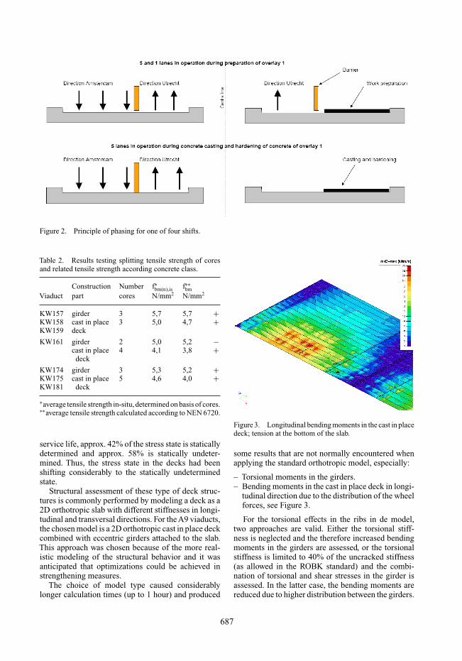
Figure 2. Principle of phasing for one of four shifts.
Table 2. Results testing splitting tensile strength of coresand related tensile strength according concrete class.
Construction Number f∗bm(n),is f∗∗bm
Viaduct part cores N/mm2 N/mm2
KW157 girder 3 5,7 5,7 +KW158 cast in place 3 5,0 4,7 +KW159 deck
KW161 girder 2 5,0 5,2 −cast in place 4 4,1 3,8 +
deck
KW174 girder 3 5,3 5,2 +KW175 cast in place 5 4,6 4,0 +KW181 deck
∗average tensile strength in-situ, determined on basis of cores.∗∗average tensile strength calculated according to NEN 6720.
service life, approx. 42% of the stress state is staticallydetermined and approx. 58% is statically undeter-mined. Thus, the stress state in the decks had beenshifting considerably to the statically undeterminedstate.
Structural assessment of these type of deck struc-tures is commonly performed by modeling a deck as a2D orthotropic slab with different stiffnesses in longi-tudinal and transversal directions. For the A9 viaducts,the chosen model is a 2D orthotropic cast in place deckcombined with eccentric girders attached to the slab.This approach was chosen because of the more real-istic modeling of the structural behavior and it wasanticipated that optimizations could be achieved instrengthening measures.
The choice of model type caused considerablylonger calculation times (up to 1 hour) and produced
Figure 3. Longitudinal bending moments in the cast in placedeck; tension at the bottom of the slab.
some results that are not normally encountered whenapplying the standard orthotropic model, especially:
– Torsional moments in the girders.– Bending moments in the cast in place deck in longi-
tudinal direction due to the distribution of the wheelforces, see Figure 3.
For the torsional effects in the ribs in de model,two approaches are valid. Either the torsional stiff-ness is neglected and the therefore increased bendingmoments in the girders are assessed, or the torsionalstiffness is limited to 40% of the uncracked stiffness(as allowed in the ROBK standard) and the combi-nation of torsional and shear stresses in the girder isassessed. In the latter case, the bending moments arereduced due to higher distribution between the girders.
687
Compared to the transversal bending moments inthe cast in place deck as derived from the conventionalorthotropic slab modeling, the transversal bendingmoments in the chosen model were considerably lower.This can partly be explained by the torsional stiffnessof the girders which contra-acts the bending curvaturesof the cast in place deck. Also, the actual transversalbending moments proved to be less than the usuallyassumed sum of the ‘distribution function’ of the slaband the local moments due to wheel loads between thegirders. The maximum moments caused by the ‘distri-bution function’ of the slab did not coincide with themaximum local bending moments. In assessing theslab bending moments in this way, the strengtheningof some viaducts could be avoided.
The outer girders proved to yield the highest bend-ing moments and shear forces. These are consideredfor the checks in the ULS and the SLS. For thechecks on fatigue strength, the actual lane layout onthe viaduct (with an emergency lane at the edge) hasbeen taken into account.
6 PRE-STRESS IN THE GIRDER
By calculating the effects of construction sequence,pre-stress, creep and shrinkage of the girders and thecast in place deck, it could be demonstrated that thepre-stress in the girder will not significantly distributeover the combined cross-section. Due to creep andshrinkage of the young cast in place deck on the(already older) girders, the pres-stress force remainsalmost completely in the girder.
This enables large calculation benefits, because ofthe design rules of NEN 6720 (design of concretestructures) where the permissible tension stress in thegirder due to bending is related to the average pre-stress in the girder. A higher average pre-stress leadsto a higher compression zone and thus to cracks ofsmaller depth in the girder.
7 STRENGTHENING OPTIONS
Three of the seven investigated viaducts proved to haveadequate strength for a surplus service life of minimum15 years, thus needed no strengthening. Four viaductshad structural shortcomings such as insufficient rein-forcement in the cast in place deck at the supports, hightension stresses in the girders at mid-span or insuf-ficient transversal reinforcement in the cast in placedeck. All of these shortcomings can be solved using areinforced concrete overlay of approximately 100 mmthickness.
Strengthening by applying carbon sheets has beenconsidered as well, but the capacity to reduce tensionstresses in the SLS in pre-stressed girders is limited
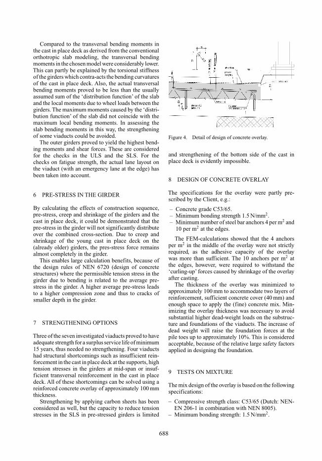
Figure 4. Detail of design of concrete overlay.
and strengthening of the bottom side of the cast inplace deck is evidently impossible.
8 DESIGN OF CONCRETE OVERLAY
The specifications for the overlay were partly pre-scribed by the Client, e.g.:
– Concrete grade C53/65.– Minimum bonding strength 1.5 N/mm2.– Minimum number of steel bar anchors 4 per m2 and
10 per m2 at the edges.
The FEM-calculations showed that the 4 anchorsper m2 in the middle of the overlay were not strictlyrequired, as the adhesive capacity of the overlaywas more than sufficient. The 10 anchors per m2 atthe edges, however, were required to withstand the‘curling-up’ forces caused by shrinkage of the overlayafter casting.
The thickness of the overlay was minimized toapproximately 100 mm to accommodate two layers ofreinforcement, sufficient concrete cover (40 mm) andenough space to apply the (fine) concrete mix. Min-imizing the overlay thickness was necessary to avoidsubstantial higher dead-weight loads on the substruc-ture and foundations of the viaducts. The increase ofdead weight will raise the foundation forces at thepile toes up to approximately 10%. This is consideredacceptable, because of the relative large safety factorsapplied in designing the foundation.
9 TESTS ON MIXTURE
The mix design of the overlay is based on the followingspecifications:
– Compressive strength class: C53/65 (Dutch: NEN-EN 206-1 in combination with NEN 8005).
– Minimum bonding strength: 1.5 N/mm2.
688
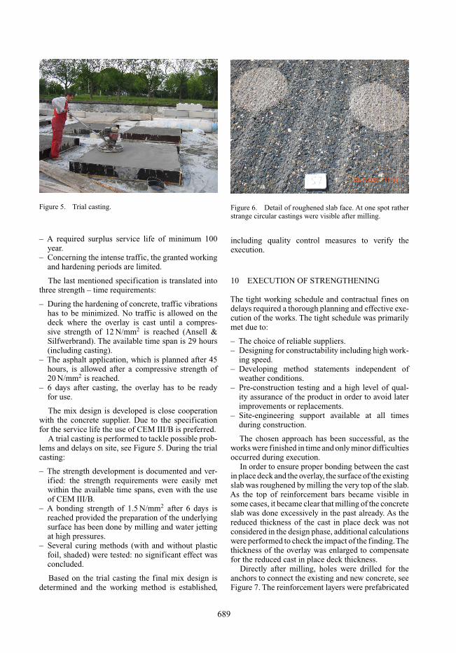
Figure 5. Trial casting.
– A required surplus service life of minimum 100year.
– Concerning the intense traffic, the granted workingand hardening periods are limited.
The last mentioned specification is translated intothree strength – time requirements:
– During the hardening of concrete, traffic vibrationshas to be minimized. No traffic is allowed on thedeck where the overlay is cast until a compres-sive strength of 12 N/mm2 is reached (Ansell &Silfwerbrand). The available time span is 29 hours(including casting).
– The asphalt application, which is planned after 45hours, is allowed after a compressive strength of20 N/mm2 is reached.
– 6 days after casting, the overlay has to be readyfor use.
The mix design is developed is close cooperationwith the concrete supplier. Due to the specificationfor the service life the use of CEM III/B is preferred.
A trial casting is performed to tackle possible prob-lems and delays on site, see Figure 5. During the trialcasting:
– The strength development is documented and ver-ified: the strength requirements were easily metwithin the available time spans, even with the useof CEM III/B.
– A bonding strength of 1.5 N/mm2 after 6 days isreached provided the preparation of the underlyingsurface has been done by milling and water jettingat high pressures.
– Several curing methods (with and without plasticfoil, shaded) were tested: no significant effect wasconcluded.
Based on the trial casting the final mix design isdetermined and the working method is established,
Figure 6. Detail of roughened slab face. At one spot ratherstrange circular castings were visible after milling.
including quality control measures to verify theexecution.
10 EXECUTION OF STRENGTHENING
The tight working schedule and contractual fines ondelays required a thorough planning and effective exe-cution of the works. The tight schedule was primarilymet due to:
– The choice of reliable suppliers.– Designing for constructability including high work-
ing speed.– Developing method statements independent of
weather conditions.– Pre-construction testing and a high level of qual-
ity assurance of the product in order to avoid laterimprovements or replacements.
– Site-engineering support available at all timesduring construction.
The chosen approach has been successful, as theworks were finished in time and only minor difficultiesoccurred during execution.
In order to ensure proper bonding between the castin place deck and the overlay, the surface of the existingslab was roughened by milling the very top of the slab.As the top of reinforcement bars became visible insome cases, it became clear that milling of the concreteslab was done excessively in the past already. As thereduced thickness of the cast in place deck was notconsidered in the design phase, additional calculationswere performed to check the impact of the finding.Thethickness of the overlay was enlarged to compensatefor the reduced cast in place deck thickness.
Directly after milling, holes were drilled for theanchors to connect the existing and new concrete, seeFigure 7. The reinforcement layers were prefabricated
689
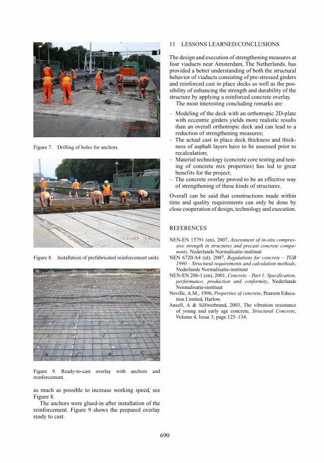
Figure 7. Drilling of holes for anchors.
Figure 8. Installation of prefabricated reinforcement units.
Figure 9. Ready-to-cast overlay with anchors andreinforcement.
as much as possible to increase working speed, seeFigure 8.
The anchors were glued-in after installation of thereinforcement. Figure 9 shows the prepared overlayready to cast.
11 LESSONS LEARNED/CONCLUSIONS
The design and execution of strengthening measures atfour viaducts near Amsterdam, The Netherlands, hasprovided a better understanding of both the structuralbehavior of viaducts consisting of pre-stressed girdersand reinforced cast in place decks as well as the pos-sibility of enhancing the strength and durability of thestructure by applying a reinforced concrete overlay.
The most interesting concluding remarks are:
– Modeling of the deck with an orthotropic 2D-platewith eccentric girders yields more realistic resultsthan an overall orthotropic deck and can lead to areduction of strengthening measures;
– The actual cast in place deck thickness and thick-ness of asphalt layers have to be assessed prior torecalculation;
– Material technology (concrete core testing and test-ing of concrete mix properties) has led to greatbenefits for the project;
– The concrete overlay proved to be an effective wayof strengthening of these kinds of structures.
Overall can be said that constructions made withintime and quality requirements can only be done byclose cooperation of design, technology and execution.
REFERENCES
NEN-EN 13791 (en), 2007, Assessment of in-situ compres-sive strength in structures and precast concrete compo-nents, Nederlands Normalisatie-instituut
NEN 6720/A4 (nl), 2007, Regulations for concrete – TGB1990 – Structural requirements and calculation methods,Nederlands Normalisatie-instituut
NEN-EN 206-1 (en), 2001, Concrete – Part 1: Specification,performance, production and conformity, NederlandsNormalisatie-instituut
Neville, A.M., 1996, Properties of concrete, Pearson Educa-tion Limited, Harlow.
Ansell, A & Silfwerbrand, 2003, The vibration resistanceof young and early age concrete, Structural Concrete,Volume 4, Issue 3, page 125–134.
690