Strength and bonding in reduced ironsand-coal compacts
43
University of Wollongong University of Wollongong Research Online Research Online Faculty of Engineering and Information Sciences - Papers: Part A Faculty of Engineering and Information Sciences 2013 Strength and bonding in reduced ironsand-coal compacts Strength and bonding in reduced ironsand-coal compacts R J. Longbottom University of Wollongong, [email protected] B J. Monaghan University of Wollongong, [email protected] S A. Nightingale University of Wollongong, [email protected] J G. Mathieson BlueScope Steel Research Follow this and additional works at: https://ro.uow.edu.au/eispapers Part of the Engineering Commons, and the Science and Technology Studies Commons Recommended Citation Recommended Citation Longbottom, R J.; Monaghan, B J.; Nightingale, S A.; and Mathieson, J G., "Strength and bonding in reduced ironsand-coal compacts" (2013). Faculty of Engineering and Information Sciences - Papers: Part A. 1485. https://ro.uow.edu.au/eispapers/1485 Research Online is the open access institutional repository for the University of Wollongong. For further information contact the UOW Library: [email protected]
Transcript of Strength and bonding in reduced ironsand-coal compacts

University of Wollongong University of Wollongong
Research Online Research Online
Faculty of Engineering and Information Sciences - Papers: Part A
Faculty of Engineering and Information Sciences
2013
Strength and bonding in reduced ironsand-coal compacts Strength and bonding in reduced ironsand-coal compacts
R J. Longbottom University of Wollongong, [email protected]
B J. Monaghan University of Wollongong, [email protected]
S A. Nightingale University of Wollongong, [email protected]
J G. Mathieson BlueScope Steel Research
Follow this and additional works at: https://ro.uow.edu.au/eispapers
Part of the Engineering Commons, and the Science and Technology Studies Commons
Recommended Citation Recommended Citation Longbottom, R J.; Monaghan, B J.; Nightingale, S A.; and Mathieson, J G., "Strength and bonding in reduced ironsand-coal compacts" (2013). Faculty of Engineering and Information Sciences - Papers: Part A. 1485. https://ro.uow.edu.au/eispapers/1485
Research Online is the open access institutional repository for the University of Wollongong. For further information contact the UOW Library: [email protected]

Strength and bonding in reduced ironsand-coal compacts Strength and bonding in reduced ironsand-coal compacts
Abstract Abstract In this investigation, the strength and bonding within reduced ironsand-coal compacts were studied, with the aim of better understanding the binding mechanisms in the reduced compacts and, based on this understanding, to improve their strength. Ironsand ore and sub-bituminous coal were mixed and pressed into compacts, which were reduced by heating in a thermogravimetric furnace to temperatures between 1273 and 1573 K under argon. The progress of the reaction was monitored by measuring the weight loss with time. The reduced compacts were found to have low strength in compression testing. The main form of bonding between the reduced ironsand particles in the compact was by the formation of a slag-like material. Increasing the final reduction temperature was found to have a profound effect on the strength of the compacts by promoting the formation of this slag-like material.
Keywords Keywords compacts, coal, ironsand, strength, reduced, bonding
Disciplines Disciplines Engineering | Science and Technology Studies
Publication Details Publication Details Longbottom, R. J., Monaghan, B. J., Nightingale, S. A. & Mathieson, J. G. 2013, 'Strength and bonding in reduced ironsand-coal compacts', Ironmaking and Steelmaking, vol. 40, no. 5, pp. 381-389.
This journal article is available at Research Online: https://ro.uow.edu.au/eispapers/1485

1
Strength and Bonding in Reduced Ironsand-Coal Compacts
Raymond J. Longbottom, University of Wollongong, PYROmetallurgical Research Group,
University of Wollongong, Wollongong, NSW 2522, Australia
Brian J. Monaghan, University of Wollongong, PYROmetallurgical Research Group,
University of Wollongong, Wollongong, NSW 2522, Australia
Sharon A. Nightingale, University of Wollongong, PYROmetallurgical Research Group,
University of Wollongong, Wollongong, NSW 2522, Australia
John G. Mathieson, BlueScope Steel Research, P.O. Box 202, Port Kembla, NSW 2505,
Australia

2
Abstract
In this investigation the strength and bonding within reduced ironsand-coal compacts were
studied. The aim of the study was to better understand the binding mechanisms in the reduced
compacts and, based on this understanding, to improve on their strength.
Ironsand ore and sub-bituminous coal were mixed and pressed into compacts which were
reduced by heating in a thermogravimetric furnace (TGA) to temperatures between 1273-
1573K under argon. The progress of the reaction was monitored by measuring the weight loss
with time. The reduced compacts were found to have low strength in compression testing. The
main form of bonding between the reduced ironsand particles in the compact was by the
formation of a slag-like material. Increasing the final reduction temperature was found to have
a profound effect on the strength of the compacts by promoting the formation of this slag-like
material.
Keywords: direct reduction; ironsand; titanomagnetite; iron ore-coal compact; bonding

3
1. Introduction
Climate change and the emissions of gases such as carbon dioxide, as well as rising energy
costs, are issues of increasing importance to the steel industry. With the greater pressures on
the steel industry to reduce the consumption of carbon to provide a corresponding decrease in
the emission of carbon dioxide, there has been increasing interest in the use of iron ore-coal
compacts in ironmaking processes.
The interest in iron ore-coal compacts is due to their advantage of having the iron oxides and
carbonaceous reductant in intimate contact. This close contact between the reactants generally
has the effect of increasing the reduction rate 1-6
. Iron ore-carbon compacts are being utilised
in new ironmaking processes such as FASTMET, ITmk3 or HiQIP 7.
As well as the faster reduction kinetics, another advantage of using iron ore-carbon compacts
for the reduction of iron ore is that a wide variety of both iron sources and carbonaceous
materials can be used. The use of iron ore-carbon compacts allows the use of different iron
sources such as iron ore fines, low grade iron ores 6, plant waste
3,8 or magnetite ores
9. The
use of different carbon sources such as coal, coke 4, biomass
10,11 and plastic waste
12-14 have
also been investigated.
In this study the focus is on the use of an ironsand, a titanomagnetite ore in the form of fairly
uniformly sized grains. The ironsand ore is significantly different to conventional hematite
iron ores, containing high amounts of titanium and with the iron contained in a magnetite-
ulvöspinel (Fe3O4-Fe2TiO4) solid solution 15
. This ore has significantly different reduction
characteristics than hematite ores 16-25
. The chemistry and morphology of ironsand have a
large effect on its reduction behaviour. Previous studies have shown that carbothermal
reduction of ironsand is slower than for a typical hematite ore 26
.

4
There have been few published studies into the strength of reduced iron ore-coal compacts.
These compacts need sufficient strength to withstand discharge, storage and handling that
may occur during transfer from the reduction unit to the melting furnace. Takano and Mourão
27 studied the use of cement as a binder in iron ore-coal compacts. They found that when
cement is used as a binder, the strength of the compact after heating is related to the strength
of the green compacts. They also reported that at higher reduction temperatures, above
1573K, that the sintering of the reduced iron begins to play an important role in the strength
of the compacts. Murakami, et al. 28
published microstructures of reduced compacts in which
at higher temperatures the metallic iron is held together by a slag phase.
The effect of atypical raw materials in iron ore-coal compacts on the strength of the reduced
compacts has not been extensively studied. Tanaka, et al. 29
studied iron ore-coal compacts
with high coal contents. They found that the strength and density of the reduced compacts
decreased with increasing coal content. Strength in these compacts was either due to a metal
or carbon matrix, depending on the composition of the compact.
The aim of this study is to develop an understanding of the reduction of ironsand-coal
compacts and how the strength of the reduced compacts is generated. The kinetics of
reduction of ironsand-coal compacts was assessed in the temperature range 1273-1573K and
the reduced compacts were characterised in terms of strength and microstructure. The effects
of changing the coal blend and the use of rice husks were also tested with a view to
understanding possible changes in the raw materials.

5
2. Experimental
Ironsand-coal compacts were prepared from three different mixtures of raw materials for use
in reduction trials. The composition of the different compact types is given in Table 1. The
different compacts were prepared to assess the effects of additions on the different types of
bonding within the reduced compacts. Compact #1 was the base case; compact #2 tested the
effect of the addition of a more fluid coking coal to the coal blend on the formation of a
remnant carbon structure in the reduced compacts; and compact #3 tested the effect of the
addition of rice husks on the formation of an oxide phase in the reduced compacts. The
compositions of the raw materials are given in Tables 2 and 3.
The compacts were prepared by initially mixing the dry ingredients together. The wet
ingredients were then added to the dry mixture, and then mixed. Molasses and water were
added as binders. The molasses used was massecuite A. A nominal 25 g of the resulting
mixture was pressed into 25 mm diameter cylinders using a pressure of 6.9 MPa for 30
seconds. After pressing, the compacts were dried and stored overnight in an oven at
approximately 383K.
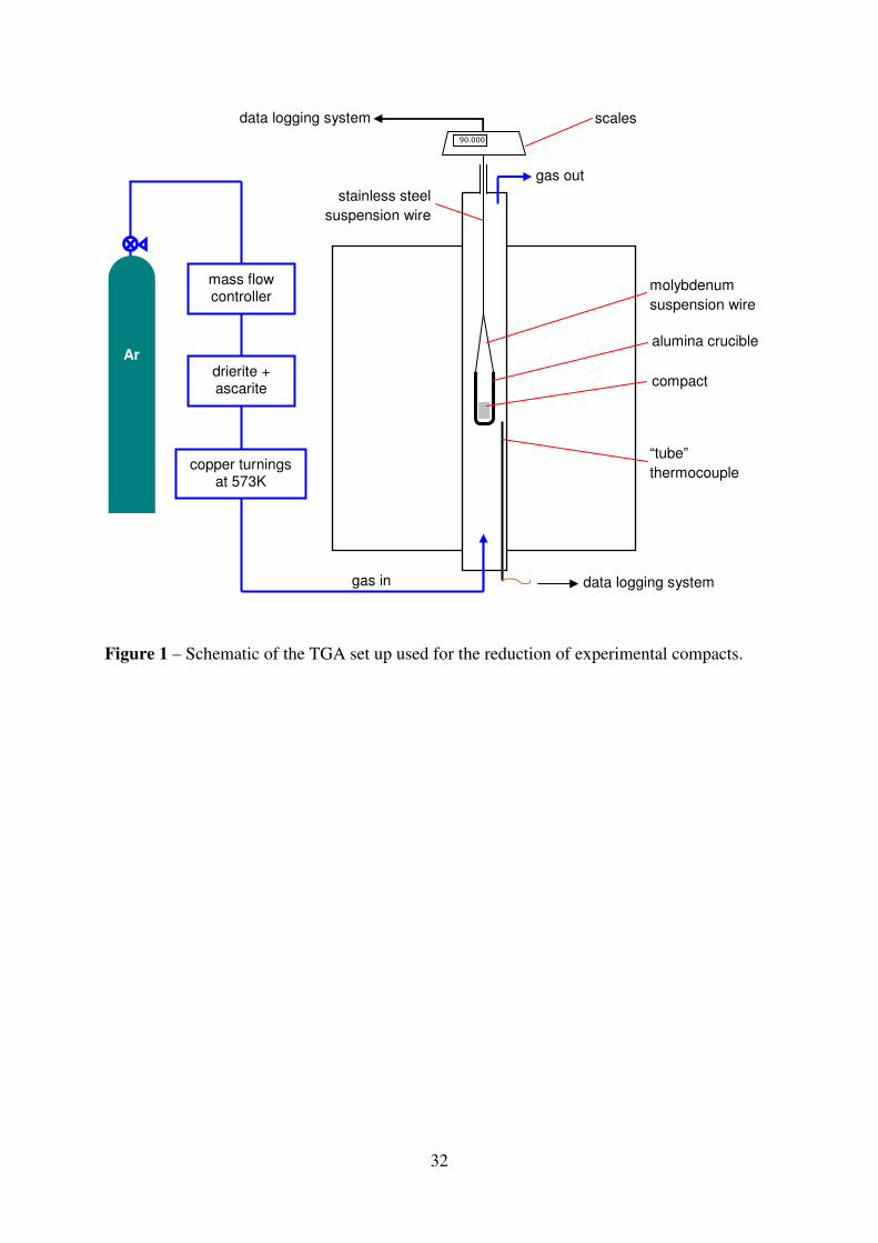
Reduction of the ironsand-coal compacts was conducted by heating the compacts under argon
in a thermogravimetric analysis (TGA) system. A schematic of the experimental set up is
shown in Fig. 1. In the reduction experiments both the effect of temperature and compact
material on the reduction and strength and microstructure of the reduced compacts were
evaluated. A base case was established, reducing compact #1 at 1573K, against which the
effect of the different variables could be compared. Details of the experimental plan are given
in Table 4.
The ironsand-coal compacts were heated at 10K min-1
under high purity argon, and then held
at the maximum temperature for at least 30 minutes or until the weight of the sample changed

6
less than 0.1 g over 5 minutes. The compacts were held inside an alumina crucible that had
holes machined into the sides and bottom to allow the ingress and exit of gas. The initial
weight of the compact was measured before placing it into the crucible. After the reduction at
temperature, the sample was cooled to room temperature under argon. The crucible containing
the compact was removed from the furnace, and the compact carefully removed from the
crucible. The weight of the reduced compact was measured. The reduced compacts were then
used for strength measurements or for mounting for characterisation of the microstructures by
scanning electron microscopy (SEM) combined with energy dispersive spectroscopy (EDS)
for elemental analysis.
The metallisation of the reduced compacts was calculated subject to the following
assumptions:
• Volatiles were completely removed from the coal and played no part in the reduction;
• Calcination of the hydrated lime was complete; and
• The molasses was reacted from the compact.
These accounted for weight changes due to other processes other than the reactions between
iron oxides and carbon. Metallic iron was formed from the ore by the reduction of magnetite
or ulvöspinel, with the overall equations which do not represent the reduction mechanism
shown in the reactions 1 and 2.
1/3Fe3O4 + 4/3C → Fe + 4/3CO(g) (1)
1/2Fe2TiO4 + C → Fe + 1/2TiO2 + CO(g) (2)
The metallisation of the compacts was calculated from the mass change of the sample after
reaction, using equation 3. Metallisation of the DRI, as opposed to a degree of reduction,

7
gives more information about its value as a product for subsequent steelmaking processes as it
takes the form of the iron into account.
ashFeironsandFe
TiO
FeTiO
TiO
COTiO
molevol
CO
Fe
mm
M
Mm
M
Mmmmmm
M
M
met,,
limexp
2
2
2
222
4
3
+
⋅+
⋅−−−−∆⋅
= (3)
Where met is the metallisation, ∆mexp is the experimental weight change, mvol is the mass of
volatiles in the compact, mlime is the mass change associated with the calcination of the
hydrated lime, mmol is the mass of molasses in the compact, 2TiOm is the total mass of TiO2 in
the compact calculated from the ironsand and compact composition, mFe,ironsand is the total
mass of iron in the ironsand, mFe,ash is the total mass of iron in the coal ash, and MFe, MCO and
2TiOM are the molar masses of Fe, CO and TiO2, respectively.
The strength of the reduced compacts was tested by compression testing using an Instron
5566 bench top unit. The load on the sample was increased at 1 N s-1
until sample failure. The
peak load reached was reported as the compressive strength of the sample. The load was
measured by a 1 kN load cell.
Both unreduced and reduced ironsand-coal compacts were mounted in epoxy resin. These
were sectioned approximately half way along the axis, then ground and polished to a 1 µm
diamond finish. The polished samples were then examined under a Leica DMRM optical
microscope and a JEOL JSM 6490LV SEM/EDS. EDS was used to provide semi-quantitative
elemental analyses of different points within the cross-sections of the samples and elemental
mapping.
8
3. Results
3.1 Reduction of Ironsand-Coal Compacts
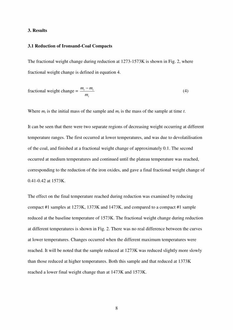
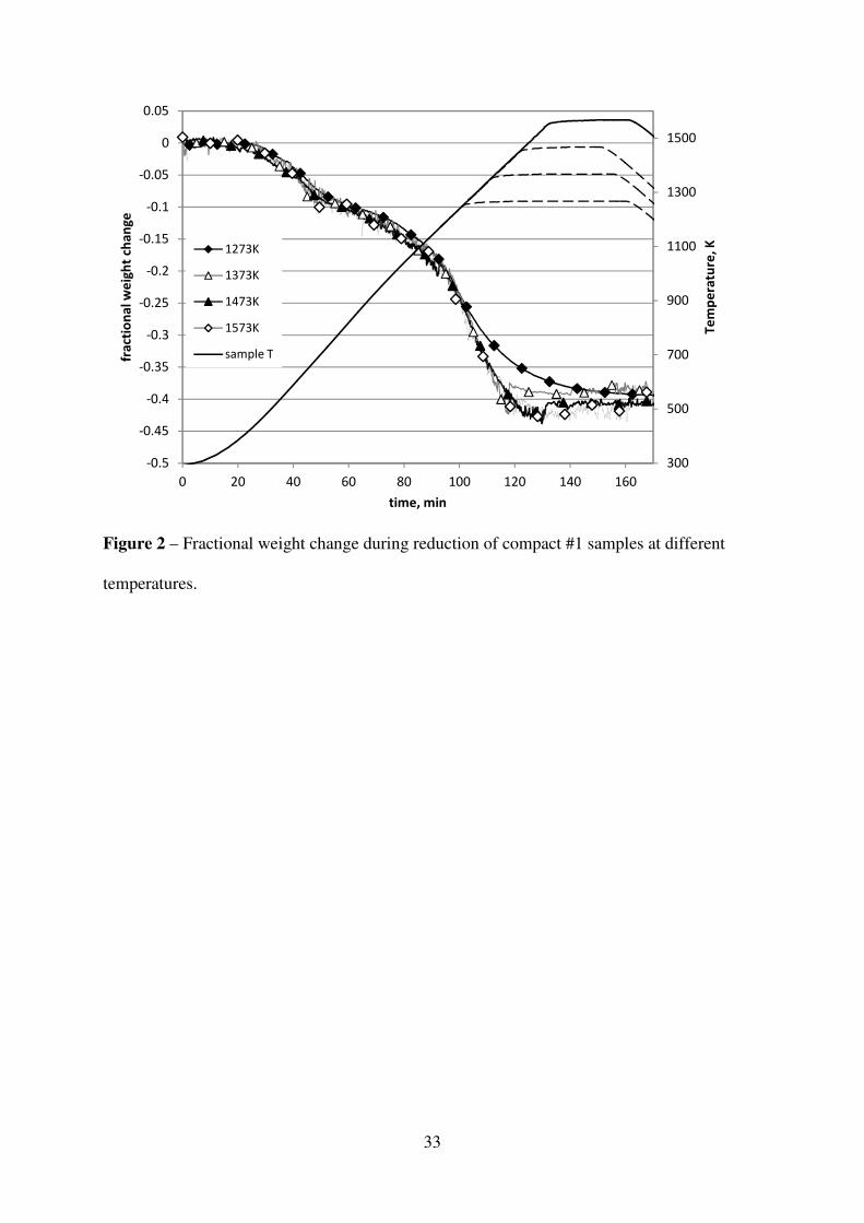
The fractional weight change during reduction at 1273-1573K is shown in Fig. 2, where
fractional weight change is defined in equation 4.
fractional weight change = i
it
m
mm − (4)
Where mi is the initial mass of the sample and mt is the mass of the sample at time t.
It can be seen that there were two separate regions of decreasing weight occurring at different
temperature ranges. The first occurred at lower temperatures, and was due to devolatilisation
of the coal, and finished at a fractional weight change of approximately 0.1. The second
occurred at medium temperatures and continued until the plateau temperature was reached,
corresponding to the reduction of the iron oxides, and gave a final fractional weight change of
0.41-0.42 at 1573K.
The effect on the final temperature reached during reduction was examined by reducing
compact #1 samples at 1273K, 1373K and 1473K, and compared to a compact #1 sample
reduced at the baseline temperature of 1573K. The fractional weight change during reduction
at different temperatures is shown in Fig. 2. There was no real difference between the curves
at lower temperatures. Changes occurred when the different maximum temperatures were
reached. It will be noted that the sample reduced at 1273K was reduced slightly more slowly
than those reduced at higher temperatures. Both this sample and that reduced at 1373K
reached a lower final weight change than at 1473K and 1573K.
9
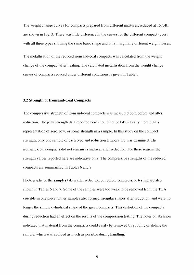
The weight change curves for compacts prepared from different mixtures, reduced at 1573K,
are shown in Fig. 3. There was little difference in the curves for the different compact types,
with all three types showing the same basic shape and only marginally different weight losses.
The metallisation of the reduced ironsand-coal compacts was calculated from the weight
change of the compact after heating. The calculated metallisation from the weight change
curves of compacts reduced under different conditions is given in Table 5.
3.2 Strength of Ironsand-Coal Compacts
The compressive strength of ironsand-coal compacts was measured both before and after
reduction. The peak strength data reported here should not be taken as any more than a
representation of zero, low, or some strength in a sample. In this study on the compact
strength, only one sample of each type and reduction temperature was examined. The
ironsand-coal compacts did not remain cylindrical after reduction. For these reasons the
strength values reported here are indicative only. The compressive strengths of the reduced
compacts are summarised in Tables 6 and 7.
Photographs of the samples taken after reduction but before compressive testing are also
shown in Tables 6 and 7. Some of the samples were too weak to be removed from the TGA
crucible in one piece. Other samples also formed irregular shapes after reduction, and were no
longer the simple cylindrical shape of the green compacts. This distortion of the compacts
during reduction had an effect on the results of the compression testing. The notes on abrasion
indicated that material from the compacts could easily be removed by rubbing or sliding the
sample, which was avoided as much as possible during handling.

10
Green compacts were found to exhibit a reasonable amount of strength, with 1310 kPa
required to crush a representative sample. The green compacts were found to be robust, and
survived handling well.
The temperature of reduction is a significant factor in the strength of the reduced ironsand-
coal compacts, as can be seen from Table 6. At low reduction temperatures, 1273-1373K, the
reduced compacts did not have enough strength to be removed from the crucible. At 1473K
the sample had very little strength, requiring less than 1 kg to crush it. At 1573K the reduced
compact displayed some strength, but not enough for survival in transportation within an
industrial plant.
From Table 7 it can be seen that the compact type also played a large role in determining the
strength of the reduced compacts. Replacement of half of the coal with the fluid coking coal
in compact #2 was found to dramatically lower the strength of the reduced compact.
Replacing half of the paper binder with the rice husks in compact #3 slightly increased the
crush strength of the sample measured. Neither sample could be considered to be strong.
3.3 Characterisation of Reduced Ironsand-Coal Compacts
The microstructures of reduced ironsand-coal compacts were characterised by examining
polished cross-sections by SEM. Semi-quantitative elemental analysis was conducted on
specific points in the samples by EDS along with qualitative analysis by elemental mapping
of areas of interest. The microstructures of the reduced compacts were used to observe the
way that the compacts were held together, as well as the effect of temperature and compact
type on the bonding.

11
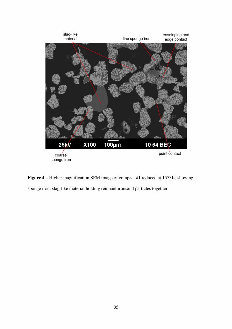
An SEM image of a type #1 compact reduced at 1573K is shown in Fig. 4. The ironsand
grains have been reduced, showing a sponge iron structure. There were varying levels of
coarseness of iron sponge. Coarse sponge iron structures were associated with the slag-like
material. Ironsand particles were joined together by a slag-like material, by point contact
between particles, along an edge of a particle or by completely enveloping several particles.
The slag-like material contained two different phases, represented by the two different shades
of grey that can be seen. Semi-quantitative elemental analysis was conducted on several
points in the cross-section of the reduced compact #1, shown in Fig. 5. The slag-like material
consisted of two phases, the majority being a silicon-rich oxide phase, and the other being
predominantly a magnesium silicate. The silicon-rich phase contained quite high levels of
calcium oxides, and more of the other gangue elements, such as titanium, than the magnesium
silicate. There was little evidence of metallic network formation, with only incipient metal
phase bonds having formed. There was no carbonaceous phase bonding.
To examine the effect of temperature on the microstructure, compact #1 samples reduced at
1273K, 1373K and 1473K were cross-sectioned and their microstructures compared to those
of a samples reduced at the baseline temperature of 1573K. The samples reduced at 1273K
and 1373K, shown in Fig. 6, showed little of the slag-like material joining reduced ironsand
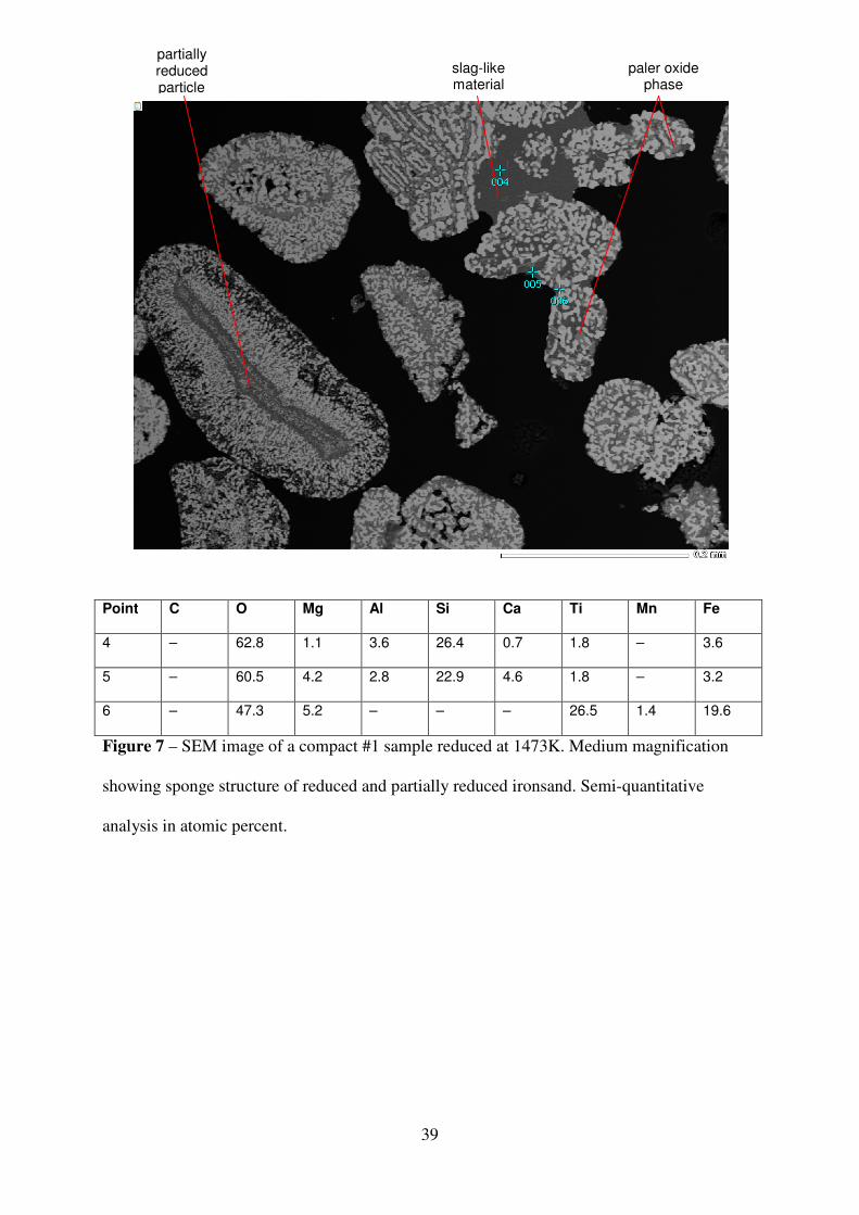
particles, as seen in the compact reduced at 1573K. An SEM image and EDS analysis of a
compact reduced at 1473K are shown in Fig. 7. The formation of the slag-like material had
begun at this temperature, and it could be seen holding some ironsand grains together.
Analysis of the bonding slag-like oxide phase shows that it was predominantly silicon rich.
A compact #2 sample, containing 50% substitution by the fluid, coking coal, reduced at
1573K is seen in Fig. 8. The slag-like material binding ironsand particles together was again
present, but in this case mostly by point contact between particles. Again there was no
12
evidence of carbonaceous phase bonding, though there is some metallic bonding between
ironsand particles.
An SEM image a sample of compact #3 containing the rice husks as well as elemental
analysis of different points within the image are shown in Fig. 9. The rice husks in this study
were added as a mixture of large particles and fine dust. There was evidence of the slag-like
material holding some ironsand particles together. This slag-like material enveloped several
of the reduced ironsand particles, holding them together, as could be seen with the baseline
type. The slag-like material in this image appeared to consist of three different oxide phases,
one rich in silicon, one richer in magnesium and the other rich in calcium and titanium, which
is likely to be high melting point perovskite (CaO.TiO2).

13
4. Discussion
The reduced ironsand-coal compacts that were produced during this study were not strong
enough for use in industrial processes, for example for transport to an electric arc furnace or
melter unit. Some of the reduced samples had low strength, but others had very little or none.
Any strength in the compacts was due to binding together of the individual particles and
components of the compact. This was made more difficult by consumption of material within
the compacts during reduction, increasing the distance between particles.
4.1 Baseline Conditions
Under the baseline conditions of a compact #1 sample reduced at 1573K, it was found that the
sample had a low strength. The reduced ironsand particles were being held together by a slag-
like material. The slag-like material mainly consisted of two phases, one rich in silicon and
the other rich in magnesium. The majority of this slag-like material was the paler, silicon rich
phase. The mass ratio of SiO2:MgO in the paler phase was measured to be approximately 3,
while for the darker phase it was approximately 0.5.
The sources of oxides in the system which could form the basis of the slag-like material were
the gangue in the ironsand and the ash from the coal. The majority (over 90%) of the
unreduced oxides in the compact originate from the ironsand. Overall, the ironsand gangue
has a mass ratio of SiO2:MgO of 0.69. The ash of the sub-bituminous coal has a mass ratio of
SiO2:MgO of 10.7. However, the presence of some individual grains and regions of ironsand
grains (inclusions) that were rich in silicon was noted in the original ore. It is likely that the
slag-like material has originated from this distinct phase in the original ore, before taking in
the other oxides as the temperature and reduction duration increased. This is supported by the
amount of oxide material that is trapped within the iron sponge structure that did not
contribute to the bonding between the reduced ironsand particles.

14
4.2 Effect of Temperature
The maximum temperature that was reached during reduction was a very important factor in
determining the final strength of the reduced ironsand-coal compacts. At the lower end of the
temperature range examined, 1273-1373K, there was little evidence of bonding between the
ironsand particles by either the formation of a slag-like material or carbonaceous material.
The temperatures seen by these samples during reduction may not have been high enough to
form a liquid or for coalescence of the oxide material. At temperatures of 1473K and above,
the slag-like material was found.
There are significant uncertainties in the solidus and liquidus temperatures in the CaO-MgO-
SiO2-Al2O3-TiOx systems. It is known that for slags containing relatively high amounts of
titanium, the liquidus temperature is strongly dependant on the oxidation state of the slag 30,31
.
To assess the liquidus temperatures without titania in the slag-like materials seen in the
compacts, the phase diagram for the CaO-MgO-SiO2 ternary system was examined. For the
composition of the slag-like material (simplified to approximately 32wt% CaO, 16% MgO,
52% SiO2) the liquidus temperature was approximately 1623K 32
.
To assess the effect of titania on the liquidus temperature, the literature was examined.
Ratchev and Belton 30
report liquidus temperatures in the range of 1823K-1973 for slags with
21.6% Ti; increasing with higher proportions of Ti3+
. Reduction of the titanium from Ti4+
to
Ti3+
was reported to increase the liquidus temperatures by 140K. However, their titania
containing slag compositions are not the same as those seen in the slag-like material found in
this study. For titania containing slag compositions similar to those found in this study, Zhao
et al. 33
report a liquidus temperature of approximately 1763K, measured under argon. These
15
liquidus temperatures are significantly higher than the experimental temperatures used in this
study. While it is likely that the slag-like material was formed at temperatures between the
solidus and liquidus, it also is likely that for the compositions and oxidation state of the slag-
like material that the liquidus temperatures are lower than those reported in the literature.
4.3 Effect of Compact Composition
Changes to the components of the ironsand-coal compacts were made to examine the effect of
the changing the raw materials on the strength of reduced compacts. Additions of a coking
coal (compact #2) and rice husks (compact #3) were made to examine their effects on the
bonding of the ironsand grains in the reduced compacts. These changes were planned to have
effects on different phases within the reduced compacts.
The coking coal substituted half of the coal in the compact #2 composition, as an attempt to
improve the bonding of the ironsand particles by the carbonaceous material. It was hoped that
the addition of a more fluid coal would allow a coke-like structure to be formed. However,
this sample was found to exhibit little strength after reduction. Examination of the
microstructure of a reduced compact #2 sample showed no bonding of the compact by
carbonaceous material. It was hoped that a coke-like structure would be formed from the
remnant carbonaceous material, bonding the reduced ironsand particles together. However,
this coke-like structure was not observed. Any binding between ironsand particles was due to
the formation of the slag-like material, with similar phases having similar compositions to
those found in the reduced compact #1 samples. While the coking coal has a very different
ash composition to the sub-bituminous coal used in compact #1, this caused little effect on the
composition of the slag-like material. This also indicates that the slag-like material is likely to
have formed from the gangue material in the ironsand.

16
Rice husks were introduced into the compacts as they can be seen as a cheap, waste-product
source of silica and some carbon. It was hoped that by introducing more silica into the
compacts more slag-like material would be produced and that the melting point of the slag-
like material would be lowered. Both of these could combine to enhance the binding of the
ironsand particles by the slag-like material. The microstructure of the reduced compact #3
sample showed that the slag-like material was again the main source of bonding between the
ironsand particles. The composition of the slag-like material measured by EDS was found to
be different in this case. While there were different phases seen in the slag-like material as
before, for compact #3 the paler phase that appeared to make up the majority of the slag-like
material was significantly richer in silica and lower in both magnesium and calcium oxides
than previously measured.
4.4 Improving Strength of Reduced Compacts
The compacts were produced from relatively coarse raw materials, both in terms of the coal
and the ironsand ore. The coarse raw materials would have contributed to the low strengths of
both the green and reduced compacts. A finer particle size distribution, especially of the
ironsand, would lead to better contact between particles and enhancement of the compact
strength.
Within the reduced compacts there are three phases, the metallic iron, unconsumed remnants
of the coal and oxide material from the ore gangue, coal ash and any added fluxes. To
improve the strength of reduced ironsand-coal compacts, it is necessary to enhance the
bonding of the reduced ironsand particles. Possibilities to enhance the binding within the
compacts could utilise any of the existing phases, through consolidation of the metal phase,
by the formation a carbonaceous matrix, or by enhancing the formation of the slag-like
material.

17
In the current samples, little bonding was seen in the metal phase. To improve the sintering of
the reduced iron, the temperature of reduction would have to be increased. This has the
disadvantage of requiring either more coal or energy, decreasing any reduction in carbon
usage and emissions.
The carbon remaining in the reduced compacts was in the form of dense individual particles.
This likely explains why the coal type used did not have a significant effect on the strength of
the compacts. To promote the formation of a carbonaceous matrix the amount of coking coal
used in the compacts should be increased, and the total amount of coal within the compact
should be increased to give more excess carbon in the reduced compact.
The formation of the slag-like material can also be promoted, which could be done by one of
three ways. These are increasing the temperature of the reduction, increasing the time at
temperature, or by the addition of a fluxing agent to the compact.
Both increasing the temperature of the reduction, or the time at temperature, would enhance
the formation of the slag-like phase, allowing more ironsand particles to be held together by
the slag. Increasing the temperature would require a higher energy input. Increasing the
temperature may also cause the oxide material trapped within the sponge structure to
contribute to slag formation.
Formation of the slag-like material could also be enhanced by the addition of a flux that
would lower the liquidus temperature and provide more slag-like material within the compact.
The flux could be chosen such that the slag formed would have a very low liquidus
temperature, which may subsequently increase after formation as more of the ore gangue is
incorporated into it. This has an advantage in the reduction stage in not needing more or
different forms of coal. However, this would have a negative impact at the melting stage,
requiring more energy to melt the increased amounts of slag. A significant difficulty with this

18
approach is the lack of data to enable a reasonable prediction of the liquidus temperature after
fluxing.
The proposed methods to improve the strength of the reduced compacts all have the
disadvantage of requiring either more energy or more coal than is currently being used for the
production of the current, low strength compacts. However, for this to be a viable industrial
practice, improvement of the compact strength is necessary.
5. Conclusions
This project was undertaken to develop a technique to produce suitable ironsand-coal
compacts, and to examine the strength of these compacts after reduction. The aim of the
project was to develop a better understanding of the bonding in the reduced compacts and to
improve on the strength of the compacts based on the improved understanding of the bonding.
The reduced ironsand-coal compacts had low strength when tested under compression. The
main form of bonding between the reduced ironsand particles was by the formation of a slag-
like material at higher temperatures. This slag-like material contained distinct phases. The
majority of the slag-like material was found to be in the form of a silica-rich phase also
containing lime. This was formed from a silica-rich phase that was found as distinct regions
within ironsand particles and as individual grains within the ore. Increasing the final reduction
temperature was found to have a profound effect on the strength of the compacts by
promoting the formation of this slag-like material.
Changes to the compact mixtures were made to study the effect of the composition on the
strength of the compacts. The addition of a fluid, coking coal was made to promote the
formation of a coke-like structure that could bind the ironsand particles together. However,
there was little evidence of this coke-like material in the final microstructures, and these

19
samples showed little strength. The addition of rice husks was done to enhance the formation
of the slag-like material and was observed to have some beneficial effect.
Acknowledgements
This project was funded by the University of Wollongong’s BlueScope Steel Metallurgy
Centre. The authors would also like to acknowledge the contribution of Harold Rogers during
this project.
20
References
1. M.B. Mourão and C. Takano: Miner. Process. Extr. Metall. Rev., 2003, 24, 183-202.
2. H. Konishi, K. Ichikawa and T. Usui: ISIJ International, 2010, 50 386-389.
3. K. Watanabe, S. Ueda, R. Inoue and T. Ariyama: ISIJ International, 2010, 50, 524-530.
4. S. Ueda, K. Yanagiya, K. Watanabe, T. Murakami, R. Inoue and T. Ariyama: ISIJ
International, 2009, 49, 827-836.
5. M. Kawanari, A. Matsumoto, R. Ashida and K. Miura: ISIJ International, 2011, 51, 1227-
1233.
6. K. Miura, K. Miyabayashi, M. Kawanari and R. Ashida: ISIJ International, 2011, 51, 1234-
1239.
7. S. Inaba and Y. Kimura: ISIJ International, 2004, 44, 2112-2114.
8. H. Tsutsumi, S. Yoshida and M. Tetsumoto: Kobelco Technology Review, 2010, 85-92.
9. K. Ishizaki, K. Nagata and Y. Hayashi: ISIJ International, 2007, 47, 817-822.
10. Y. Ueki, K.I. Ohno, T. Maeda, K. Nishioka and M. Shimizu: Fuel, 2010, (in press).
11. S. Ueda, S. Watanabe, K. Yanagiya, T. Murakami, R. Inoue and T. Ariyama: ISIJ
International, 2009, 49, 1505-1512.
12. K. Nishioka, T. Taniguchi, Y. Ueki, K.I. Ohno, T. Maeda and M. Shimizu: ISIJ
International, 2007, 47, 602-607.
13. T. Murakami and E. Kasai: ISIJ International, 2011, 51, 9-13.
21
14. Y. Ueki, K.I. Ohno, T. maeda, K. Nishioak and M. Shimizu: ISIJ International, 2008, 48,
1670-1675.
15. J.B. Wright: New Zealand J. Geology and Geophysics, 1964, 7, 424-444.
16. G.D. McAdam, R.E.A. Dall and T. Marshall: N.Z. J. Sci., 1969, 12, 649-668.
17. G.D. McAdam, R.E.A. Dall and T. Marshall: N.Z. J. Sci., 1969, 12, 669-686.
18. G.D. McAdam: Ironmaking and Steelmaking, 1974, 138-150.
19. E. Park: Ph.D. Thesis University of New South Wales, Sydney, Australia, 2002.
20. E. Park and O. Ostrovski: Proc. of the 1st Int. Conf. on Advanced Materials Processing,
Institute of Materials Engineering, Australasia, 2000, 87-94.
21. E. Park and O. Ostrovski: ISIJ International, 2003, 43, 1316-1325.
22. E. Park and O. Ostrovski: ISIJ International, 2004, 44, 74-81.
23. E. Park and O. Ostrovski: ISIJ International, 2004, 44, 999-1005.
24. E. Park, S.B. Lee, O. Ostrovski, D.J. Min and C.H. Rhee: ISIJ International, 2004, 44,
214-216.
25. R.J. Longbottom, O. Ostrovski and E. Park: ISIJ International, 2006, 46, 641-646.
26. N.I. Krasnova and Y.L. Krezer: Eur. J. Mineral., 1995, 7, 1361-1372.
27. C. Takano and M.B. Mourão: Miner. Process. Extr. Metall. Rev., 2003, 24, 233-252.
28. T. Murakami, T. Nishimura and E. Kasai: ISIJ International, 2009, 49, 1686-1693.

22
29. Y. Tanaka, T. Ueno, K. Okumura and S. Hayashi: ISIJ International, 2011, 51, 1240-
1246.
30. I.P. Ratchev and G.R. Belton: Proc. 5th
Int. Conf. on Molten Slags, Fluxes and Salts, ISS,
Warrendale, PA, 1997, 387-393.
31. G. Tranell, O. Ostrovski and S. Jahanshahi: Metall. Mater. Trans. B, 2002, 33B, 61-67.
32. M. Kowalski, P.J. Spencer and D. Neuschütz: Slag Atlas, ed. by Verin Duetscher
Eisenhüttenleute (VDEh), Verlag Stahleisen GmbH, Düsseldorf, 1995, 70.
33. B. Zhao, E. Jak and P. Hayes: Proc. 8th
Int. Conf. on Molten Slags, Fluxes and Slats,
Quebecor World Chile, 2009, 71-82.

23
List of Captions
Figure 1 – Schematic of the TGA set up used for the reduction of experimental compacts.
Figure 2 – Fractional weight change during reduction of compact #1 samples at different
temperatures.
Figure 3 – Weight change curves for compacts of different types reduced at 1573K.
Figure 4 – Higher magnification SEM images of compact #1 reduced at 1573K, showing
sponge iron, slag-like material and remnants of coal.
Figure 5 –Elemental analysis points within a compact #1 sample reduced at 1573K. Semi-
quantitative analysis in atomic percent.
Figure 6 – SEM images of a reduced compact #1 sample. (a) Reduced at 1273K, medium
magnification overview showing reduced titanomagnetite and coal remnants; (b) reduced at
1373K, medium magnification image showing sponge iron structure, gangue particles and
carbonaceous material.
Figure 7 – SEM images of a compact #1 sample reduced at 1473K. Medium magnification
showing sponge structure of reduced and partially reduced titanomagnetite.
Figure 8 – Higher magnification SEM images of a compact #2 sample reduced at 1573K.
Medium magnification image showing slag-like material binding reduced titanomagnetite
particles.
Figure 9 – EDS elemental analysis of points within a compact #3 sample reduced at 1573K.
Semi-quantitative analysis given in atomic percent.

24
Table 1 – Constituents of the compact types and their proportions (dry weights).
Table 2 –Composition of the ironsand.
Table 3 –Proximate and ash analyses of the coal samples.
Table 4 – Experimental plan.
Table 5 – Metallisation of reduced compacts.
Table 6 – Compressive strength of samples of compact #1 reduced at varying temperatures.
Table 7 – Compressive strength of compacts of different types, reduced at 1573K.

25
Table 1 – Constituents of the compact types and their proportions (dry weights).
compact #1 (wt%)
compact #2 (wt%)
compact #3 (wt%)
ironsand 70.7 70.7 70.7
sub-bituminous coal
23.5 11.75 23.5
coking coal – 11.75 –
lime (CaO) 2.1 2.1 2.1
paper 1.5 1.5 0.75
rice husks – – 0.75
water 1.7 1.7 1.7
molasses 1.5 1.5 1.5

26
Table 2 –Composition of the ironsand.
Weight %
Fe 59.12
TiO2 7.87
Al2O3 3.77
MgO 2.85
SiO2 1.97
CaO 0.41
MnO 0.63
V2O3 0.49
P 0.035

27
Table 3 –Proximate and ash analyses of the coal samples.
Analysis Component Sub-bituminous coal -75 µm (wt%)
Coking coal -75 µm (wt%)
Proximate analysis Inherent Moisture 7.6 1.5
Ash 5.2 10.5
Volatile Matter 40.8 30.6
Ash analysis Silicon as SiO2 34.8 53.9
Aluminium as Al2O3 12.3 32
Iron as Fe2O3 18.7 4.34
Calcium as CaO 16.8 2.14
Magnesium as MgO 3.23 0.89
Sodium as Na2O 1.34 0.59
Potassium as K2O 0.36 1.22
Titanium as TiO2 2.47 2.20
Manganese as Mn3O4 0.24 0.044
Sulfur as SO3 8.8 1.39
Phosphorus asP2O5 0.14 0.51
Strontium as SrO 0.14 0.16
Barium as BaO 0.13 0.12
Zinc as ZnO 0.03 0.04

28
Table 4 – Experimental plan.
Variable Compact type Temperature
base case compact #1 1573K
temperature compact #1 1273, 1373, 1473K
coking coal compact #2, replaces 50% of coal
1573K
rice husks compact #3, replaces 50% of paper fibre
1573K

29
Table 5 – Metallisation of reduced compacts.
Sample Final fractional weight change
Metallisation (%)
Compact #1, 1573K 0.420 97
Compact #1, 1573K 0.415 96
Compact #1, 1573K 0.424 99
Compact #1, 1273K 0.393 89
Compact #1, 1373K 0.388 87
Compact #1, 1473K 0.408 94
Compact #2, 1573K 0.402 97
Compact #3, 1573K 0.409 94

Table 6 – Compressive strength of samples of compact #1 reduced at varying temperatures.
Sample Picture
Compact #1, reduced 1273K
Compact #1, reduced 1373K
Compact #1, reduced 1473K
Compact #1, reduced 1573K
30
Compressive strength of samples of compact #1 reduced at varying temperatures.
Strength Notes
− Reduced compact crumbled into very small particles when removed from crucible. No strength.
− Reduced compact broke into small pieces during removal from crucible. No strength.
18.3 kPa Reduced compact fragile, handling with extreme care, easily abraded. Low strength.
297 kPa Reduced compact can be handled, but carefully, and can be abraded. Some strength.
10 mm
10 mm
10 mm
10 mm
Compressive strength of samples of compact #1 reduced at varying temperatures.
Reduced compact crumbled into very small particles when removed from crucible. No strength.
Reduced compact broke into small pieces during removal from crucible.
Reduced compact fragile, handling with extreme care, easily abraded. Low
Reduced compact can be handled, but carefully, and can be abraded. Some

Table 7 – Compressive strength of compacts of different types, reduced at
Sample Picture
Compact #1, reduced
Compact #2, reduced
Compact #3, reduced
31
Compressive strength of compacts of different types, reduced at
Strength Notes
297 kPa Reduced compact can be handled, but carefully, and can be abraded. Some strength.
30.9 kPa Reduced compact rather fragile, handling with care, easily abraded. Low strength.
686 kPa Reduced compact can be handled, but carefully, and can be abraded. Some strength.
10 mm
10 mm
10 mm
Compressive strength of compacts of different types, reduced at 1573K.
Reduced compact can be handled, but carefully, and can be abraded. Some
Reduced compact rather fragile, handling with care, easily abraded. Low strength.
Reduced compact can be handled, but carefully, and can be abraded. Some
32
Figure 1 – Schematic of the TGA set up used for the reduction of experimental compacts.
90.000
gas in
gas out
scales
stainless steel
suspension wire
alumina crucible
compact
“tube”
thermocouple
Ar
molybdenum
suspension wire
drierite + ascarite
copper turnings at 573K
data logging system
data logging system
mass flow controller
33
Figure 2 – Fractional weight change during reduction of compact #1 samples at different
temperatures.
300
500
700
900
1100
1300
1500
-0.5
-0.45
-0.4
-0.35
-0.3
-0.25
-0.2
-0.15
-0.1
-0.05
0
0.05
0 20 40 60 80 100 120 140 160
Te
mp
era
ture
, K
fra
ctio
na
l w
eig
ht
cha
ng
e
time, min
1273K
1373K
1473K
1573K
sample T

34
Figure 3 – Weight change curves for compacts of different types reduced at 1573K.
300
500
700
900
1100
1300
1500
-0.5
-0.45
-0.4
-0.35
-0.3
-0.25
-0.2
-0.15
-0.1
-0.05
0
0.05
0 20 40 60 80 100 120 140 160
Te
mp
era
ture
, K
fra
ctio
na
l w
eig
ht
cha
ng
e
time, min
compact 1
compact 2
compact 3
sample T
35
Figure 4 – Higher magnification SEM image of compact #1 reduced at 1573K, showing
sponge iron, slag-like material holding remnant ironsand particles together.
slag-like material
coarse sponge iron
fine sponge iron enveloping and edge contact
point contact

36
Point O Mg Al Si Ca Ti
1 60.6 6.0 4.4 14.5 10.2 4.3
2 58.0 6.6 2.6 15.7 17.1 0.0
3 59.2 9.7 7.3 10.1 7.7 6.0
4 61.9 25.2 0.2 12.1 0.5 0.2
5 61.3 25.9 0.1 11.9 0.6 0.1
Figure 5 –Elemental analysis points within a compact #1 sample reduced at 1573K. Semi-
quantitative analysis in atomic percent.
darker phase paler phase

37
Figure 6(a)
Figure 6(b)
Figure 6 – SEM images of reduced compact #1 samples. (a) Reduced at 1273K, medium
magnification overview showing reduced ironsand and coal remnants; (b) reduced at 1373K,
coarse sponge fine sponge gangue
reduced ironsand particle
gangue

38
medium magnification image showing sponge iron structure, gangue particles and
carbonaceous material.
39
Point C O Mg Al Si Ca Ti Mn Fe
4 – 62.8 1.1 3.6 26.4 0.7 1.8 – 3.6
5 – 60.5 4.2 2.8 22.9 4.6 1.8 – 3.2
6 – 47.3 5.2 – – – 26.5 1.4 19.6
Figure 7 – SEM image of a compact #1 sample reduced at 1473K. Medium magnification
showing sponge structure of reduced and partially reduced ironsand. Semi-quantitative
analysis in atomic percent.
slag-like material
paler oxide phase
partially reduced particle

40
Figure 8 – Higher magnification SEM image of a compact #2 sample reduced at 1573K.
Medium magnification image showing slag-like material binding reduced ironsand particles.
slag-like material
reduced ironsand

Point O Na Mg
1 63.1 2.4 1.3
2 58.5 – –
3 60.4 5.3 1.1
4 57.3 – 11.2
5 60.4 – 25.1
6 60.5 5.6 1.7
Figure 9 – EDS elemental analysis of points within a compact #3 sample reduced at
Semi-quantitative analysis given in atomic percent.
incipient metal phase bond
41
Al Si K Ca Ti
5.0 23.3 4.0 – 0.3
– – – 20.3 21.2
10.3 15.8 4.3 1.3 0.3
11.2 9.2 8.5 – 5.7 7.3
25.1 0.2 12.2 – 0.4 0.2
8.3 14.9 3.3 3.1 –
EDS elemental analysis of points within a compact #3 sample reduced at
quantitative analysis given in atomic percent.
medium phase darker phasepaler phase
Mn Fe
0.3 0.2
– –
0.8 0.4
0.6 0.1
1.3 0.2
2.7 –
EDS elemental analysis of points within a compact #3 sample reduced at 1573K.
darker phase