Streaming A/V Over IP Design Guide - Extron...
68
Streaming A/V Over IP Design Guide for Professional A / V Systems
-
Upload
phungkhanh -
Category
Documents
-
view
233 -
download
0
Transcript of Streaming A/V Over IP Design Guide - Extron...
Streaming A/V Over IP Design Guide
for Professional A / V Systems

Extron Streaming A/V over IP Design Guide
Every day, IP streaming of audio and video used by government, industry and consumers expands into new
applications. Surveillance, Broadcast, Corporate and Government use of IP streaming is very mature while VOIP,
desktop videoconferencing and public video on demand services continue to connect individuals to streaming
solutions every day.
The migration of AV solutions to real-time IP streaming represents the next great innovation for our industry.
Moving audio visual solutions onto IP networks represents incredible opportunities to 1.) Extend the reach
of real-time communication beyond a room or building to a global enterprise 2.) Increase the scalability of
AV distribution systems with digital quality, 3.) Simplify the wiring, installation and operation of systems and
4.) Improve the ability to document, analyze and share mixed video/graphic information used in all types of
presentations.
Each of these improvements represent opportunities to provide new organizational capabilities that increase the
efficiency of an enterprise or reduce the capital expenditure and operational costs of audio visual installations.
In the early months of 2010 Extron acquired the Products Division of Electrosonic. This acquisition brought with
it the PURE3 codec, which is applied in high-performance video and graphic streaming products which are
available now from Extron. Concurrently, Extron is now in the third year of an internal development program of
standards based H.264 streaming products. A preview of Extron’s H.264 technology was shown at InfoComm
2010. Extron offers training programs in AV streaming and IP networking topics essential to integrating
successful solutions.
Attaining proficiency in the subject of streaming A/V over IP will be essential to delivering sound streaming
solutions. This Guide represents a starting point for Extron customers. It provides reference data, information
on important technical topics, and real-world application examples, demonstrating practical uses of Extron
streaming technologies.
Extron Worldwide Sales Offices
USA West USA East Europe Middle East Asia Japan China
www.extron.com 1
TABLE OF CONTENTS
Streaming A/V Over IP for Professional Systems
Real-time Delivery of Video & Graphics Over IP . . . . . . . . . . . . . . . . . . . . . . . . . . . . . . . . . . . . . 2Understanding Video Compression . . . . . . . . . . . . . . . . . . . . . . . . . . . . . . . . . . . . . . . . . . . . . 10Ethernet Networks: Opportunities & Challenges . . . . . . . . . . . . . . . . . . . . . . . . . . . . . . . . . . . 16Handling Network Errors . . . . . . . . . . . . . . . . . . . . . . . . . . . . . . . . . . . . . . . . . . . . . . . . . . . . . . 21Extron PURE3 Codec . . . . . . . . . . . . . . . . . . . . . . . . . . . . . . . . . . . . . . . . . . . . . . . . . . . . . . . . 25Economics of Delivering Video Over IP . . . . . . . . . . . . . . . . . . . . . . . . . . . . . . . . . . . . . . . . . . 31
System Design Video & Graphic over IP
Enterprise Collaboration . . . . . . . . . . . . . . . . . . . . . . . . . . . . . . . . . . . . . . . . . . . . . . . . . . . . . . 34Command and Control - Collaboration . . . . . . . . . . . . . . . . . . . . . . . . . . . . . . . . . . . . . . . . . . . 36Remote Control of Real Time Video Production Equipment . . . . . . . . . . . . . . . . . . . . . . . . . . 38Studio to Studio Video Contribution . . . . . . . . . . . . . . . . . . . . . . . . . . . . . . . . . . . . . . . . . . . . . 40Post Production Collaboration, Content Review, and Color Grading . . . . . . . . . . . . . . . . . . . 42House of Worship . . . . . . . . . . . . . . . . . . . . . . . . . . . . . . . . . . . . . . . . . . . . . . . . . . . . . . . . . . . 44
Extron A/V Streaming Over IP Product Solutions
VN-Matrix 200 Series - RGB/DVI Over IP . . . . . . . . . . . . . . . . . . . . . . . . . . . . . . . . . . . . . . . . . 48VN-Matrix 300 Series - SDI/HD-SDI Over IP . . . . . . . . . . . . . . . . . . . . . . . . . . . . . . . . . . . . . . 50
Glossary
Streaming A/V Over IP Glossary . . . . . . . . . . . . . . . . . . . . . . . . . . . . . . . . . . . . . . . . . . . . . . . . 53
2 Extron Streaming A/V over IP Design Guide
Interaction:Two-way,Real-time
Communicationand Control
Accessibility:Content Playback
& One-way �ow
Bit Rate
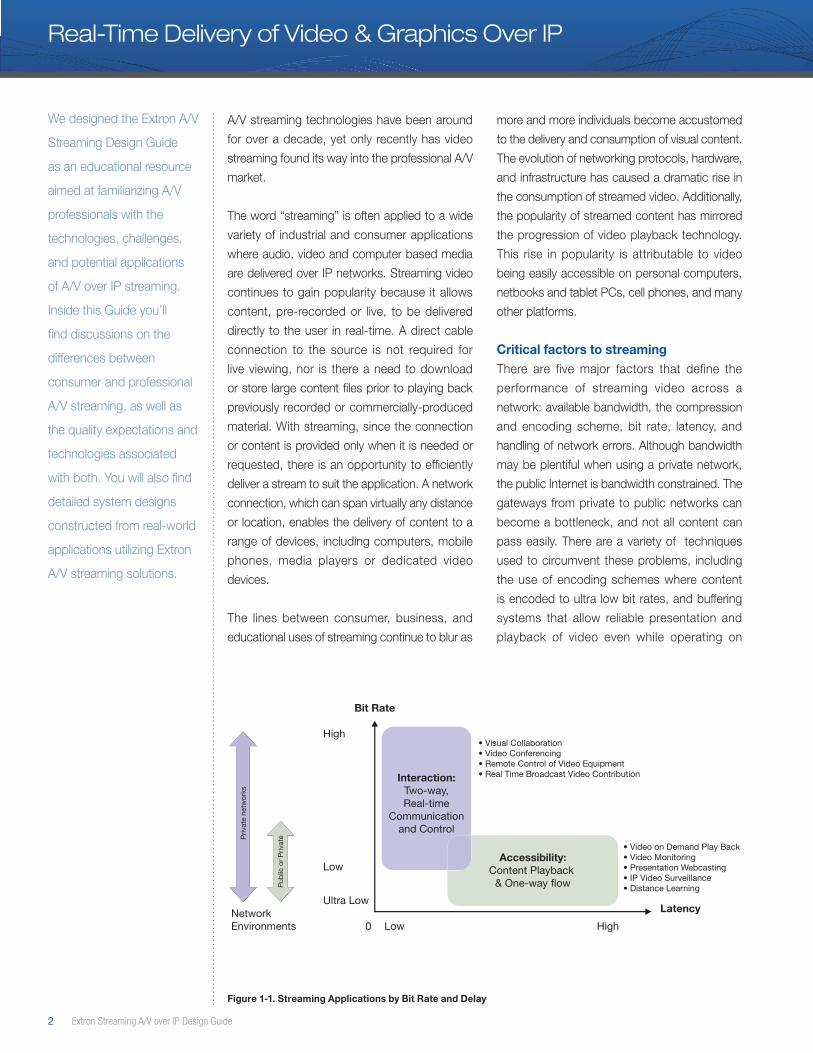
High• Visual Collaboration• Video Conferencing• Remote Control of Video Equipment• Real Time Broadcast Video Contribution
• Video on Demand Play Back • Video Monitoring• Presentation Webcasting• IP Video Surveillance• Distance Learning
Ultra LowLatency
Low
LowNetwork Environments 0 High
Streaming Applications by Bandwidth and Delay
Priv
ate
netw
orks
Pub
lic o
r P
rivat
e
Real-Time Delivery of Video & Graphics Over IP
A/V streaming technologies have been around
for over a decade, yet only recently has video
streaming found its way into the professional A/V
market.
The word “streaming” is often applied to a wide
variety of industrial and consumer applications
where audio, video and computer based media
are delivered over IP networks. Streaming video
continues to gain popularity because it allows
content, pre-recorded or live, to be delivered
directly to the user in real-time. A direct cable
connection to the source is not required for
live viewing, nor is there a need to download
or store large content files prior to playing back
previously recorded or commercially-produced
material. With streaming, since the connection
or content is provided only when it is needed or
requested, there is an opportunity to efficiently
deliver a stream to suit the application. A network
connection, which can span virtually any distance
or location, enables the delivery of content to a
range of devices, including computers, mobile
phones, media players or dedicated video
devices.
The lines between consumer, business, and
educational uses of streaming continue to blur as
more and more individuals become accustomed
to the delivery and consumption of visual content.
The evolution of networking protocols, hardware,
and infrastructure has caused a dramatic rise in
the consumption of streamed video. Additionally,
the popularity of streamed content has mirrored
the progression of video playback technology.
This rise in popularity is attributable to video
being easily accessible on personal computers,
netbooks and tablet PCs, cell phones, and many
other platforms.
Critical factors to streamingThere are five major factors that define the
performance of streaming video across a
network: available bandwidth, the compression
and encoding scheme, bit rate, latency, and
handling of network errors. Although bandwidth
may be plentiful when using a private network,
the public Internet is bandwidth constrained. The
gateways from private to public networks can
become a bottleneck, and not all content can
pass easily. There are a variety of techniques
used to circumvent these problems, including
the use of encoding schemes where content
is encoded to ultra low bit rates, and buffering
systems that allow reliable presentation and
playback of video even while operating on
Figure 1-1. Streaming Applications by Bit Rate and Delay
We designed the Extron A/V
Streaming Design Guide
as an educational resource
aimed at familiarizing A/V
professionals with the
technologies, challenges,
and potential applications
of A/V over IP streaming.
Inside this Guide you’ll
find discussions on the
differences between
consumer and professional
A/V streaming, as well as
the quality expectations and
technologies associated
with both. You will also find
detailed system designs
constructed from real-world
applications utilizing Extron
A/V streaming solutions.

www.extron.com 3
Move beyond the consumer channels of streamed content and the benchmarks for video transport and delivery take on a very different set of requirements.
unreliable networks. The latency of video arrival
due to encoding and buffering delays can affect
the usefulness of the video in some applications;
the impact of latency is often not well understood
until it is personally experienced.
Streaming content may originate as a live signal or
as a stored format that is retrievable for viewing.
Perhaps one of the most common examples
of live content is sports, where game or event
footage is streamed to the desktop or mobile
device in real time. Consumer-focused services,
including Netflix, YouTube, and Hulu, all offer
content that is intended to fit different viewing
niches. These services thrive on their ability to
make content widely accessible to a broad range
of users across the Web. The content is highly
channelized and with streaming offered in formats
suitable to meet the needs of most viewers.
Although YouTube does offer live streaming
capabilities, most of these services deliver video
that is first stored and then played back at the
convenience of the viewer. These services place
an emphasis on high availability and accessibility
from public or private networks.
Streaming is also used in a wide variety of
commercial and educational applications.
IP security cameras, media content servers,
computers, and media encoders are all examples
of devices whose primary function is to transmit
video content as packets of information across
a network. All of these devices have different
encoding, bandwidth, and bit rate consumption
characteristics, and they can all easily co-exist as
resources on the network.
One important question to ask when considering
a particular application for video streaming is,
“What are my application needs and what defines
quality in my streaming application?”
Video streaming is wholly experiential: Quality is
a relative term that depends upon how streamed
video is first encoded and then viewed. What
constitutes an ideal viewing experience for a
consumer application will not always meet the
needs of a commercial one. For example, a
viewer who watches a news event on a mobile
device has a very different expectation of quality
than a medical professional who is viewing and
participating in a medical procedure remotely.
A high quality video signal is certainly the
expectation of both users, but both applications
have taken very different approaches to meet
technical needs and quality expectations of each
user.
Not All Streaming is Equal The consumer world of video content is focused
on easy accessibility with a nearly infinite range
of content and video experiences are built
around those criteria. The content typically uses
ultra-low levels of bandwidth because it must
be transported using the public Internet. In this
environment, users are more interested in the
availability and immediacy of video programming,
and are less concerned with the delay, also
referred to as latency.
Move outside of low-bandwidth consumer-
oriented sources of streaming content and
into commercial and educational applications,
however, and the benchmarks for video transport
and delivery take on a very different set of
requirements.
Meeting spaces and classrooms for commercial
and educational users have long been designed
and installed to offer high resolution images for
many participants. The expectation in these
environments is that content will not only be
widely accessible, but it must be optimized
for very high resolution viewing experiences,
with delay low enough to allow for real time
communication. Figure 1-1 illustrates different
streaming application requirements.
Consider the needs of large, multi-national
organizations with operations separated by
vast geography. Their desire is to integrate their
operations and facilitate communication between
far-flung-staff. Low delay video delivery is the
primary focus of their streaming requirements,
4 Extron Streaming A/V over IP Design Guide
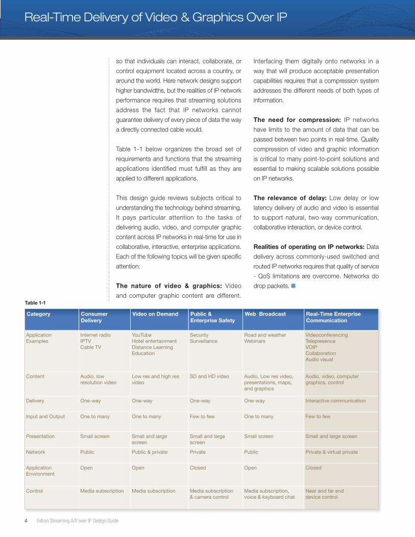
Category Consumer Delivery
Video on Demand Public & Enterprise Safety
Web Broadcast Real-Time Enterprise Communication
Application Examples
Internet radioIPTVCable TV
YouTubeHotel entertainmentDistance LearningEducation
SecuritySurveillance
Road and weatherWebinars
VideoconferencingTelepresenceVOIPCollaborationAudio visual
Content Audio, low resolution video
Low res and high res video
SD and HD video Audio, Low res video, presentations, maps, and graphics
Audio, video, computer graphics, control
Delivery One-way One-way One-way One-way Interactive communication
Input and Output One to many One to many Few to few One to many Few to few
Presentation Small screen Small and large screen
Small and large screen
Small screen Small and large screen
Network Public Public & private Private Public Private & virtual private
Application Environment
Open Open Closed Open Closed
Control Media subscription Media subscription Media subscription & camera control
Media subscription, voice & keyboard chat
Near and far end device control
so that individuals can interact, collaborate, or
control equipment located across a country, or
around the world. Here network designs support
higher bandwidths, but the realities of IP network
performance requires that streaming solutions
address the fact that IP networks cannot
guarantee delivery of every piece of data the way
a directly connected cable would.
Table 1-1 below organizes the broad set of
requirements and functions that the streaming
applications identified must fulfill as they are
applied to different applications.
This design guide reviews subjects critical to
understanding the technology behind streaming.
It pays particular attention to the tasks of
delivering audio, video, and computer graphic
content across IP networks in real-time for use in
collaborative, interactive, enterprise applications.
Each of the following topics will be given specific
attention:
The nature of video & graphics: Video
and computer graphic content are different.
Interfacing them digitally onto networks in a
way that will produce acceptable presentation
capabilities requires that a compression system
addresses the different needs of both types of
information.
The need for compression: IP networks
have limits to the amount of data that can be
passed between two points in real-time. Quality
compression of video and graphic information
is critical to many point-to-point solutions and
essential to making scalable solutions possible
on IP networks.
The relevance of delay: Low delay or low
latency delivery of audio and video is essential
to support natural, two-way communication,
collaborative interaction, or device control.
Realities of operating on IP networks: Data
delivery across commonly-used switched and
routed IP networks requires that quality of service
- QoS limitations are overcome. Networks do
drop packets. ■
Table 1-1
Real-Time Delivery of Video & Graphics Over IP
www.extron.com 5
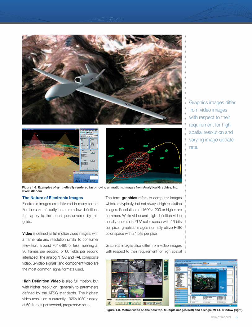
Graphics images differ from video images with respect to their requirement for high spatial resolution and varying image update rate.
Figure 1-2. Examples of synthetically rendered fast-moving animations. Images from Analytical Graphics, Inc. www.stk.com
Figure 1-3. Motion video on the desktop. Multiple images (left) and a single MPEG window (right).
The Nature of Electronic ImagesElectronic images are delivered in many forms.
For the sake of clarity, here are a few definitions
that apply to the techniques covered by this
guide.
Video is defined as full motion video images, with
a frame rate and resolution similar to consumer
television, around 704×480 or less, running at
30 frames per second, or 60 fields per second
interlaced. The analog NTSC and PAL composite
video, S-video signals, and component video are
the most common signal formats used.
High Definition Video is also full motion, but
with higher resolution, generally to parameters
defined by the ATSC standards. The highest
video resolution is currently 1920×1080 running
at 60 frames per second, progressive scan.
The term graphics refers to computer images
which are typically, but not always, high resolution
images. Resolutions of 1600×1200 or higher are
common. While video and high definition video
usually operate in YUV color space with 16 bits
per pixel, graphics images normally utilize RGB
color space with 24 bits per pixel.
Graphics images also differ from video images
with respect to their requirement for high spatial
6 Extron Streaming A/V over IP Design Guide
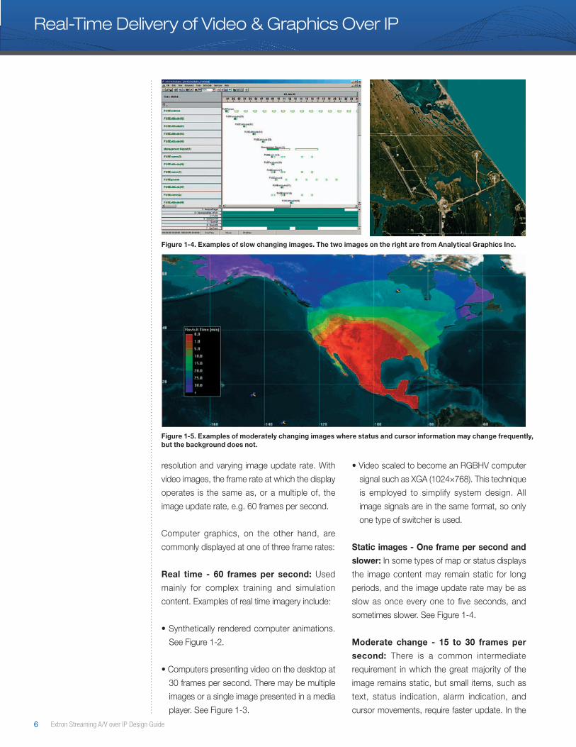
Figure 1-5. Examples of moderately changing images where status and cursor information may change frequently, but the background does not.
resolution and varying image update rate. With
video images, the frame rate at which the display
operates is the same as, or a multiple of, the
image update rate, e.g. 60 frames per second.
Computer graphics, on the other hand, are
commonly displayed at one of three frame rates:
Real time - 60 frames per second: Used
mainly for complex training and simulation
content. Examples of real time imagery include:
• Synthetically rendered computer animations.
See Figure 1-2.
• Computers presenting video on the desktop at
30 frames per second. There may be multiple
images or a single image presented in a media
player. See Figure 1-3.
• Video scaled to become an RGBHV computer
signal such as XGA (1024×768). This technique
is employed to simplify system design. All
image signals are in the same format, so only
one type of switcher is used.
Static images - One frame per second and
slower: In some types of map or status displays
the image content may remain static for long
periods, and the image update rate may be as
slow as once every one to five seconds, and
sometimes slower. See Figure 1-4.
Moderate change - 15 to 30 frames per
second: There is a common intermediate
requirement in which the great majority of the
image remains static, but small items, such as
text, status indication, alarm indication, and
cursor movements, require faster update. In the
Figure 1-4. Examples of slow changing images. The two images on the right are from Analytical Graphics Inc.
Real-Time Delivery of Video & Graphics Over IP

www.extron.com 7
Enterprise and public network bandwidths can vary dramatically depending on budgetary and environmental factors, as well as connections made available by service providers.
Figure 1-6. A transport control room may have 50 or more live video sources derived from remote cameras, combined with a dozen or so computer images derived from several different applications.
special case of cursor tracking, the update of the
cursor movement must be 15 - 30 frames per
second or equivalent, even if the remainder of the
image has a slower frame rate. Figure 1-5.
Defining NetworksFor the purposes of this guide, networks are
defined as computer networks working to IEEE
802.3 Ethernet standards.
Four data rates are currently defined for operation
over optical fiber and twisted-pair cables:
• 10 Mbps - 10Base-T Ethernet (IEEE 802.3)• 100 Mbps - Fast Ethernet (IEEE 802.3u)• 1000 Mbps - Gigabit Ethernet (IEEE 802.3z)• 10-Gigabit - 10 Gbps Ethernet (IEEE 802.3ae).
The availability of 10 Gbps network equipment is
growing, but broad deployment of this bandwidth
is not yet commonplace. Enterprise and public
network bandwidths can vary dramatically
depending on budgetary and environmental
factors, as well as connections made available
by service providers. The following are typical
service types available:
• ISDN: 64–128 kbps
• Cable broadband: 6 Mbps
• LAN switching backbones of 10 - 140 Gbps
Traditional Means of Connecting Images from Source to DisplayUntil very recently, the traditional means of
connecting images from source to display has
been by analog signal distribution using point-
to-point cable connections dedicated to this
single purpose. Video is usually distributed using
a single coaxial cable carrying a composite
signal. Graphics and professional video images
expanded on this scenario also the use multiple
coaxial cables; for example YCbCr or YUV for
professional video and RGBHV for computer
graphics. For convenience, video is often scaled
to computer resolutions such as XGA, and
converted to RGB color space, so it can be
distributed on the same cable as the computer-
generated content. A mature range of equipment
is available for distributing and switching
these signals, including computer interfaces,
distribution amplifiers, simple switchers, and
matrix or routing switchers.
Long distance transmission of video historically
relied upon RF modulation techniques. As cost
drops and infrastructure becomes more common,
fiber optic distribution is becoming increasingly
popular for long distance transmission of both
video and graphics signals.
The use of balun, balanced-unbalanced,
techniques has also allowed these analog signals
to be distributed over twisted pair cables, typically
CAT5 and CAT6 network cables, to simplify and
lower the cost of installation. It is worth noting
that this technology is the basis of most KVM
extender solutions. It is an analog signaling
technique, susceptible to high frequency roll-off
if cables are poor quality or too long.
Digital signal distribution is also common for video
and graphics content. In the broadcast field, well
established standards like SDI and HD-SDI, are
utilized, supporting distances up to 1,000 feet
(330 meters) on a single coaxial cable for SDI,
and up to 330 feet (100 meters), for HD-SDI.
DVI is an accepted standard of delivering a digital
image signal from a source, usually a computer,
to a display. However, the DVI standard supports
only very short distances, typically 16 feet (5
meters) and requires a complex multicore cable.
8 Extron Streaming A/V over IP Design Guide
Real-Time Delivery of Video & Graphics Over IP
Extron offers many product to extend the rand
of DVI signals, each well suited to specific
applications. See the chart below for practical
transmission distance limitations.
HDMI is also increasingly popular as more and
more consumer products such as DVD and
Blu-ray Disc players, and flat panel displays and
projectors, are equipped with this technology.
The current variety of analog and digital
connection options continues to provide design
challenges for A/V professionals. See the Extron
Digital Design Guide for more information on
DVI and HDMI connections.
Multi-Image Systems and Their Distribution NeedsMany professional, corporate, security, industrial,
and defense users now require multiple image
sources and multiple displays within a large
location or spread over several locations.
Utilization is diverse, ranging from sophisticated
presentation and conferencing facilities to
transport and surveillance control rooms in
military applications.
In all of these applications, the conventional
distribution of images requires a lot of dedicated
coaxial cable and/or twisted pair cabling. For
practical and cost reasons the method of image
selection using matrix switchers and interfaces
is customized to each installation and display
location.
Why Networks for Image Distribution?Interfacing and delivering electronic images on a
computer network provides potential economic
and operational advantages. If a facility already
has a network infrastructure in place, then some
of these advantages can be achieved:
• Extend the reach of signal distribution to destinations that are not practical to connect using traditional methods. The destinations could be across a building, campus, country or around the world.
• Reduce the need to install dedicated cable infrastructure, particularly to destinations which may change over time.
• Increase the flexibility in choice of images. If all inputs, video and graphic are distributed on the same cable, greater flexibility will exist for the end point displays.
• Increase the flexibility in the location of displays. Displays could be added or moved at any time to any location a network connection exists.
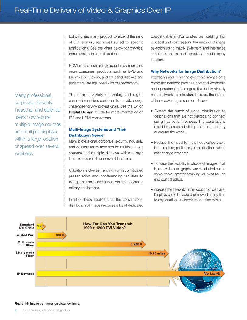
StandardDVI Cable
18.75 miles
No Limit!
How Far Can You Transmit1920 x 1200 DVI Video?How Far Can You Transmit1920 x 1200 DVI Video?
MultimodeFiber
SinglemodeFiber
IP Network
Twisted Pair
3,200 ft
15 ft
100 ft
Figure 1-8. Image transmission distance limits.
Many professional, corporate, security, industrial, and defense users now require multiple image sources and multiple displays within a large location or spread over several locations.

www.extron.com 9
Displays could be added or moved at any time to any location a network connection exists.
Figure 1-7. The main presentation theater at the National Defense University at Fort McNair, Washington DC has a high resolution display able to show multiple images under TV lighting conditions. Photo by Sgt Linda Tsang, Army Visual Information Directorate.
Coax Twisted Pair Fiber IP Networks
Installation Intra-building Intra-building Intra or extra building Intra or extra building
Cabling Fixed plant Fixed plant Fixed plant Flexible plant
Scalability Limited Limited Limited Unlimited
Transmission distance 1m ~150m 20m – 300m 20m - 30km Unlimited
I/O node locations Fixed Fixed Fixed Flexible
Integrated recording No No No Yes
Air-gap possible No No No Yes
Max . Distance (RGBHV) Up to 300m with DA’s 300m with CAT5 > 30km single mode fiber Unlimited
Conduit space Accessible Accessible Accessible Accessible scarce
Transmission Analog Analog Digital Digital
System Passive Active Active Active
Influence from EM fields Yes Yes No No
Radiation Yes / un-secure Yes / un-secure No/Secure Twisted pair, Yes / un-secureOptical, No / secure
Remote Power No need Possible Not possible not possible
Cost Function of cable length Fixed cost for T & R Fixed cost for T & R Encoder and decodercost, plus network
• Increase the capability to exploit available visual imagery in collaborative working arising from the fact that any location can now access any networked image.
• Record content streamed on the network.
• A networked solution has the potential to reduce the amount of conduit, cable, weight and resulting energy use. ■
Table 1-2. Compression of signal transmission methods
Traditional signal distribution technologies continue to provide quality and cost effective connections for audio, video and computer graphics. Streaming solutions expand system capabilities, increase the flexibility of endpoint locations and extend geographic reach. In many applications, existing network infrastructure, the benefits are of real-time collaboration over long distances, and scalability requirements necessitate and IP streaming solution. Successful AV professionals will apply both traditional signal distribution and IP streaming solutions in combination to provide the best current and future value for customers.
10 Extron Streaming A/V over IP Design Guide
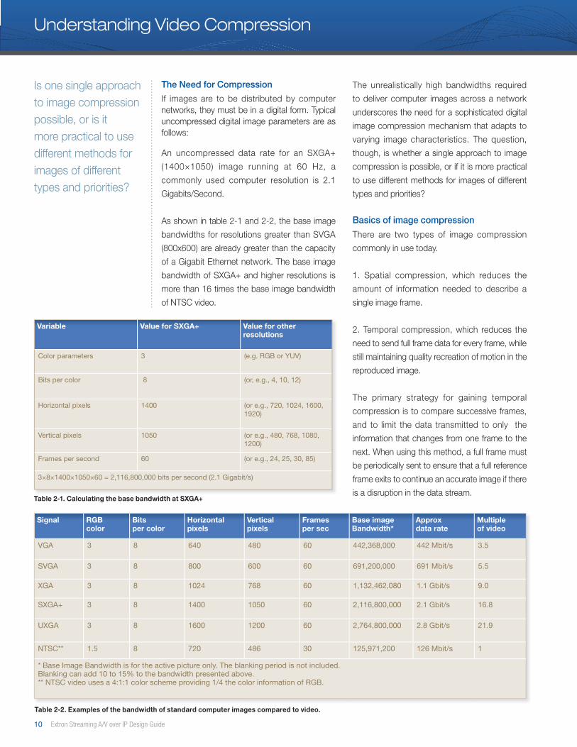
Variable Value for SXGA+ Value for otherresolutions
Color parameters 3 (e .g . RGB or YUV)
Bits per color 8 (or, e .g ., 4, 10, 12)
Horizontal pixels 1400 (or e .g ., 720, 1024, 1600, 1920)
Vertical pixels 1050 (or e .g ., 480, 768, 1080, 1200)
Frames per second 60 (or e .g ., 24, 25, 30, 85)
3×8×1400×1050×60 = 2,116,800,000 bits per second (2 .1 Gigabit/s)
Understanding Video Compression
Is one single approach to image compression possible, or is it more practical to use different methods for images of different types and priorities?
The Need for Compression
If images are to be distributed by computer networks, they must be in a digital form. Typical uncompressed digital image parameters are as follows:
An uncompressed data rate for an SXGA+
(1400×1050) image running at 60 Hz, a
commonly used computer resolution is 2.1
Gigabits/Second.
As shown in table 2-1 and 2-2, the base image
bandwidths for resolutions greater than SVGA
(800x600) are already greater than the capacity
of a Gigabit Ethernet network. The base image
bandwidth of SXGA+ and higher resolutions is
more than 16 times the base image bandwidth
of NTSC video.
The unrealistically high bandwidths required
to deliver computer images across a network
underscores the need for a sophisticated digital
image compression mechanism that adapts to
varying image characteristics. The question,
though, is whether a single approach to image
compression is possible, or if it is more practical
to use different methods for images of different
types and priorities?
Basics of image compression
There are two types of image compression
commonly in use today.
1. Spatial compression, which reduces the
amount of information needed to describe a
single image frame.
2. Temporal compression, which reduces the
need to send full frame data for every frame, while
still maintaining quality recreation of motion in the
reproduced image.
The primary strategy for gaining temporal
compression is to compare successive frames,
and to limit the data transmitted to only the
information that changes from one frame to the
next. When using this method, a full frame must
be periodically sent to ensure that a full reference
frame exits to continue an accurate image if there
is a disruption in the data stream.
Signal RGBcolor
Bitsper color
Horizontalpixels
Verticalpixels
Framesper sec
Base imageBandwidth*
Approxdata rate
Multipleof video
VGA 3 8 640 480 60 442,368,000 442 Mbit/s 3 .5
SVGA 3 8 800 600 60 691,200,000 691 Mbit/s 5 .5
XGA 3 8 1024 768 60 1,132,462,080 1 .1 Gbit/s 9 .0
SXGA+ 3 8 1400 1050 60 2,116,800,000 2 .1 Gbit/s 16 .8
UXGA 3 8 1600 1200 60 2,764,800,000 2 .8 Gbit/s 21 .9
NTSC** 1 .5 8 720 486 30 125,971,200 126 Mbit/s 1
* Base Image Bandwidth is for the active picture only . The blanking period is not included .Blanking can add 10 to 15% to the bandwidth presented above .** NTSC video uses a 4:1:1 color scheme providing 1/4 the color information of RGB .
Table 2-2. Examples of the bandwidth of standard computer images compared to video.
Table 2-1. Calculating the base bandwidth at SXGA+
www.extron.com 11
SOURCEIMAGE TRANSFORM QUANTIZE
ENCODETRANSMIT REORDER
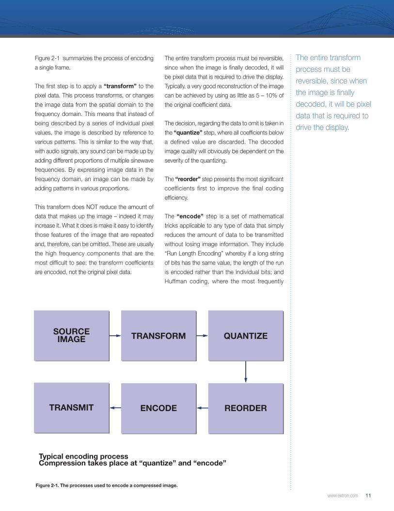
Typical encoding processCompression takes place at “quantize” and “encode”
Figure 2-1. The processes used to encode a compressed image.
Figure 2-1 summarizes the process of encoding
a single frame.
The first step is to apply a “transform” to the
pixel data. This process transforms, or changes
the image data from the spatial domain to the
frequency domain. This means that instead of
being described by a series of individual pixel
values, the image is described by reference to
various patterns. This is similar to the way that,
with audio signals, any sound can be made up by
adding different proportions of multiple sinewave
frequencies. By expressing image data in the
frequency domain, an image can be made by
adding patterns in various proportions.
This transform does NOT reduce the amount of
data that makes up the image – indeed it may
increase it. What it does is make it easy to identify
those features of the image that are repeated
and, therefore, can be omitted. These are usually
the high frequency components that are the
most difficult to see; the transform coefficients
are encoded, not the original pixel data.
The entire transform process must be reversible,
since when the image is finally decoded, it will
be pixel data that is required to drive the display.
Typically, a very good reconstruction of the image
can be achieved by using as little as 5 – 10% of
the original coefficient data.
The decision, regarding the data to omit is taken in
the “quantize” step, where all coefficients below
a defined value are discarded. The decoded
image quality will obviously be dependent on the
severity of the quantizing.
The “reorder” step presents the most significant
coefficients first to improve the final coding
efficiency.
The “encode” step is a set of mathematical
tricks applicable to any type of data that simply
reduces the amount of data to be transmitted
without losing image information. They include
“Run Length Encoding” whereby if a long string
of bits has the same value, the length of the run
is encoded rather than the individual bits; and
Huffman coding, where the most frequently
The entire transform process must be reversible, since when the image is finally decoded, it will be pixel data that is required to drive the display.
12 Extron Streaming A/V over IP Design Guide
Understanding Video Compression
Visually lossless is a subjective term, but is taken to mean that to a trained observer the displayed image is indistinguishable from the original.
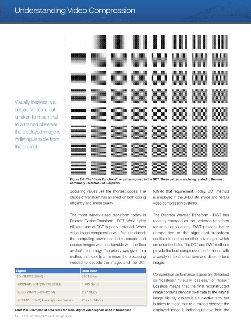
Figure 2-2. The “Basis Functions”, or patterns, used in the DCT. These patterns are being related to the most commonly used block of 8×8 pixels.
occurring values use the shortest codes. The
choice of transform has an effect on both coding
efficiency and image quality.
The most widely used transform today is
Discrete Cosine Transform - DCT. While highly
efficient, use of DCT is partly historical. When
video image compression was first introduced,
the computing power needed to encode and
decode images was considerable with the then
available technology. The priority was given to a
method that kept to a minimum the processing
needed to decode the image, and the DCT
fulfilled that requirement. Today, DCT method
is employed in the JPEG still image and MPEG
video compression systems.
The Discrete Wavelet Transform - DWT has
recently emerged as the preferred transform
for some applications. DWT provides better
compaction of the significant transform
coefficients and some other advantages which
are described later. The DCT and DWT methods
provide the best compression performance with
a variety of continuous tone and discrete tone
images.
Compression performance is generally described
as “lossless,” “visually lossless,” or “lossy.”
Lossless means that the final reconstructed
image contains identical pixel data to the original
image. Visually lossless is a subjective term, but
is taken to mean that to a trained observer the
displayed image is indistinguishable from the
Signal Data Rate
SDI (SMPTE 259M) 270 Mbit/s
HDSDI/HD-SDTI (SMPTE 292M) 1 .485 Gbit/s
3G SDI (SMPTE 424/425 M) 2 .97 Gbit/s
DV (SMPTE314M) Uses light compression 25 or 50 Mbit/s
Table 2-3. Examples of data rates for serial digital video signals used in broadcast

www.extron.com 13
original. Lossy images are acknowledged to be of
lower quality than the original, but are adequate or
better than adequate for the intended application.
Users selecting a lossy compression method
have chosen bandwidth as a priority over image
quality.
Existing Compression Standards for Still Images
Many different compression methods exist. They
have evolved as technology has advanced and
as the underlying techniques have become better
understood. In many applications proprietary
methods provide performance that set them
apart as the most practical option. Even where
standards exist, there are always many variants
within the standard: the compression mechanism
is built based on a standard, but may not be
applied as a standard and therefore may not be
interoperable. This especially applies to moving
image standards. Within a system it will always
be necessary to carry out a compatibility audit.
Let’s take a look at this issue. NTSC is a
standard. If you connect an NTSC source to an
NTSC display with a coaxial cable, the image is
always decoded to present an image. However,
if you are presented with a datastream identified
as “MPEG-4”, you will need to know what
“flavor” or variant of MPEG-4 is being used. You
might find, for example, that the MPEG video
from a surveillance encoder produced by one
manufacturer, though based on the MPEG-4
standard, may not be decoded by an MPEG-4
decoder produced by another manufacturer.
For still, continuous tone-grayscale and color
images, there are two leading standards, both
developed by the Joint Photographic Experts
Group - JPEG of the ISO. Both are intended for
images of any size.
• JPEG, the original standard, is based on the
DCT. The DCT itself works on a “pixel block”
basis, and the block size used is 8×8.
• JPEG2000, a newer standard, is based on
the DWT to achieve better compression. This
standard employs a variable tile concept,
not standardized blocks. This variable can
be defined differently for each application
or image. The selection of the tiling or block
size is based on the source image creation
application, and not the display.
Both standards require symmetrical processing
equal power to encode and decode the
information. Although primarily intended for still
images, the exchange of photographic image
files, JPEG and JPEG2000 can be used for
motion images or the continuous presentation
of computer images, simply by encoding each
frame separately.
Motion JPEG - M-JPEG has been widely used for
video, both in semi-professional video and in the
security surveillance field. Because each frame
is encoded separately, there is no frame inter-
dependence. Editing and random access are
easily facilitated in product designs. Consumer
and semi-professional digital video work on the
same basis, but are not fully JPEG compliant.
JPEG2000 has been chosen by the Digital
Cinema Initiatives - DCI group within the
motion picture industry as the preferred
method of distributing digital cinema programs.
Digitally encoded films are stored, and played
back from hard disk in this application.
Neither M-JPEG nor JPEG2000 has any provision
for temporal compression. If they are applied in a
manner which is compliant with the standard ,
they will be unable to reach the bandwidth targets
to support scalable streaming of many real-time
video/graphics sources on an enterprise network
environment.
Existing Compression Standards for Moving Images
Compression standards for motion images have
evolved from two different approaches but, at
the high end, the two families have now come
together.
Even where standards exist, there are always many variants within the standard. This means the compression mechanism is built based on a standard, but may not be applied as a standard and therefore may not be interoperable.
14 Extron Streaming A/V over IP Design Guide
I1
Original frame sequence
Transmitted frame sequence
I10
B2
B3
B8
B9
B5
B6
P7
P4
I1
B9
P4
B2
I10
B8
P7
B5
P5
B3
Understanding Video Compression
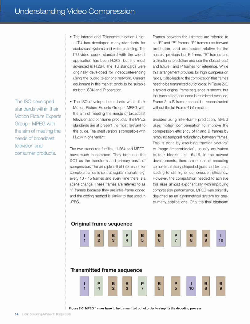
Figure 2-3. MPEG frames have to be transmitted out of order to simplify the decoding process
The ISO developed standards within their Motion Picture Experts Group - MPEG with the aim of meeting the needs of broadcast television and consumer products.
• The International Telecommunication Union
- ITU has developed many standards for
audiovisual systems and video encoding. The
ITU video codec standard with the widest
application has been H.263, but the most
advanced is H.264. The ITU standards were
originally developed for videoconferencing
using the public telephone network. Current
equipment in this market tends to be suitable
for both ISDN and IP operation.
• The ISO developed standards within their
Motion Picture Experts Group - MPEG with
the aim of meeting the needs of broadcast
television and consumer products. The MPEG
standards are at present the most relevant to
this guide. The latest version is compatible with
H.264 in one variant.
The two standards families, H.264 and MPEG,
have much in common. They both use the
DCT as the transform and primary basis of
compression. The principle is that information for
complete frames is sent at regular intervals, e.g.
every 10 - 15 frames and every time there is a
scene change. These frames are referred to as
“I” frames because they are intra-frame coded
and the coding method is similar to that used in
JPEG.
Frames between the I frames are referred to
as “P” and “B” frames. “P” frames use forward
prediction, and are coded relative to the
nearest previous I or P frame. “B” frames use
bidirectional prediction and use the closest past
and future I and P frames for reference. While
this arrangement provides for high compression
ratios, it also leads to the complication that frames
need to be transmitted out of order. In Figure 2-3,
a typical original frame sequence is shown, but
the transmitted sequence is reordered because,
Frame 2, a B frame, cannot be reconstructed
without the full Frame 4 information.
Besides using inter-frame prediction, MPEG
uses motion compensation to improve the
compression efficiency of P and B frames by
removing temporal redundancy between frames.
This is done by ascribing “motion vectors”
to image “macroblocks”, usually equivalent
to four blocks, i.e. 16×16. In the newest
developments, there are means of encoding
complete arbitrary shaped objects and textures,
leading to still higher compression efficiency.
However, the computation needed to achieve
this rises almost exponentially with improving
compression performance. MPEG was originally
designed as an asymmetrical system for one-
to-many applications. Only the final bitstream

www.extron.com 15
is a standard. It determines how a decoder
must work, the aim being that decoding should
be simpler than encoding. Encoding, on the
other hand, uses proprietary methods, and this
approach has seen amazing improvements in
compression performance over the last few years.
The challenge with this type of system is that the
more efficient the method, the more intensive
the processing required. The best performance
comes from either very expensive or non-real time
systems. The MPEG standards have evolved as
technology permitted new applications. The full
standards allow for dramatic variations in image
specification, but practical executions impose
restraints. In general, the following conditions
apply:
• MPEG-1, the original standard, was designed
with the limitations of the standard CD in
mind. It works for progressive scan images of
video resolution, and normal bit rates are up
to around 1.8 Mbps. A common resolution is
352×240 at 29.97 frames per second to carry
an NTSC image.
• MPEG-2 addressed the limitations of MPEG-1
and became a huge success. It is the basis of
satellite and multi-channel cable broadcasting,
and of consumer products such as DVD and
Personal Video Recorders. In its most common
form, MPEG-2 covers both progressive and
interlace scan standard definition video images
(e.g. 720×480 at 30 fps) with bit rates up to 15
Mbps. In practice, excellent results are obtained
using 2 – 6 Mbps. “Higher Level” variants of
MPEG-2 are suitable for High Definition video
at resolutions up to 1920×1080 and bit rates
typically 19 – 80 Mbps. A 4:2:2 version is also
defined with rates up to 300 Mbps.
• MPEG-4, the latest variant, builds on the
previous work with a priority of achieving very
low bit rates, dealing with errors, and meeting
consumer demand for multiplatform support.
With MPEG-4, a content provider is able to
run the same program material on both large
screen televisions and miniature screen cell
phones. MPEG-4 also provides for still image
encoding, including use of the DWT. One part
of the standard, MPEG-4 part 10 AVC, is the
same as H.264.
The H.264 standard offers 17 different sets
of capabilities, referred to as profiles, which
can be applied to many different classes of
applications. H.264 has dramatically increased
the efficiency of this compression technology
and includes a new method of intra-prediction
for encoding I-frames and reducing bandwidth
while maintaining quality. Intra-prediction takes
advantage of the spatial redundancy within a
frame. It checks the macroblocks to the left and
above the macroblock currently being encoded to
determine if there is a close match. Once it finds a
match Intra-prediction uses a vector to point to it
and encodes the difference between the two. For
example, a frame showing a background with a
large surface area will benefit from intraprediction
because the spatial redundancy is exploited,
resulting in increased compression. This has
proven to be far more efficient than prior methods
of I-frame encoding.
H.264 also provides the opportunity to improve
compression by applying block-based motion
compensation used in P and B frames. This
allows the encoder to search for matching blocks
and the search parameters can be adjusted to
improve the odds of a match. Where no matching
blocks can be found in the macroblocking
process, an intra-coding method is again used.
The H.264 standard also provides the means to
include in-loop deblocking filters. These allow
the edges of encoded blocks to be smoothed,
reducing the effect of the commonly seen block
artifacts seen in Motion JPEG and other MPEG
standards.
In principle, of all the MPEG standards result in a
bitstream which can be converted into a file for
non real-time working. So, in principle, any MPEG
bitstream can be sent over a computer network.
However, the characteristics of networks
introduce a number of practical problems. ■
H.264 is quickly replacing MPEG-2 as the more popular compression in many industrial applications.
16 Extron Streaming A/V over IP Design Guide
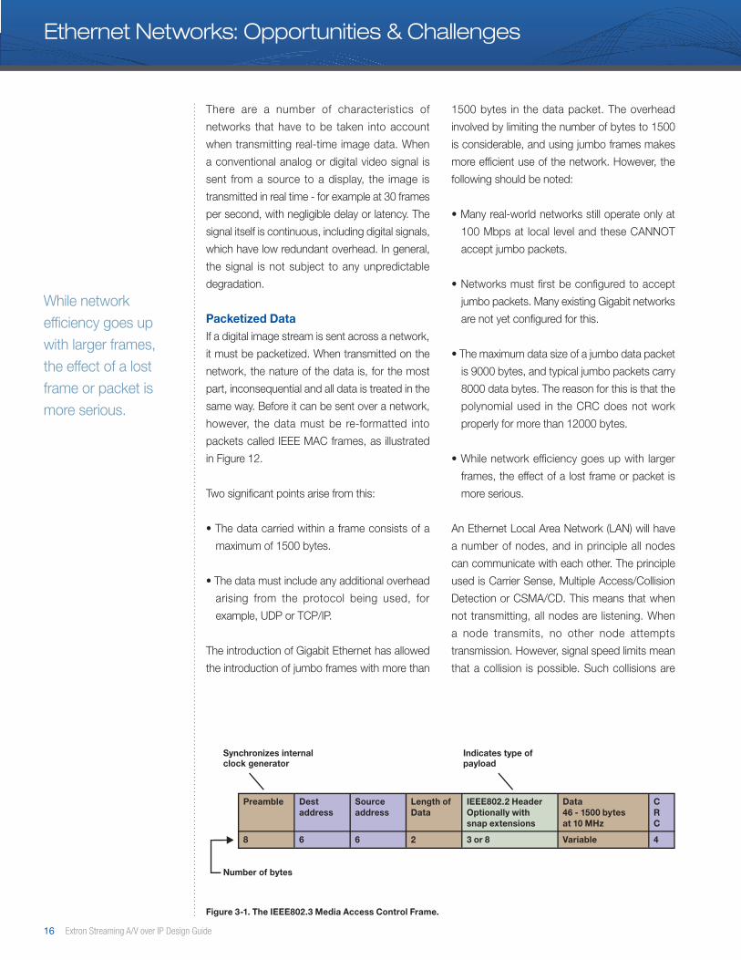
Figure 3-1. The IEEE802.3 Media Access Control Frame.
Preamble
Synchronizes internalclock generator
Indicates type ofpayload
Number of bytes
Destaddress
Sourceaddress
Length of Data
IEEE802.2 HeaderOptionally withsnap extensions
Data46 - 1500 bytesat 10 MHz
CRC
8 6 6 2 3 or 8 Variable 4
Ethernet Networks: Opportunities & Challenges
While network efficiency goes up with larger frames, the effect of a lost frame or packet is more serious.
There are a number of characteristics of
networks that have to be taken into account
when transmitting real-time image data. When
a conventional analog or digital video signal is
sent from a source to a display, the image is
transmitted in real time - for example at 30 frames
per second, with negligible delay or latency. The
signal itself is continuous, including digital signals,
which have low redundant overhead. In general,
the signal is not subject to any unpredictable
degradation.
Packetized DataIf a digital image stream is sent across a network,
it must be packetized. When transmitted on the
network, the nature of the data is, for the most
part, inconsequential and all data is treated in the
same way. Before it can be sent over a network,
however, the data must be re-formatted into
packets called IEEE MAC frames, as illustrated
in Figure 12.
Two significant points arise from this:
• The data carried within a frame consists of a
maximum of 1500 bytes.
• The data must include any additional overhead
arising from the protocol being used, for
example, UDP or TCP/IP.
The introduction of Gigabit Ethernet has allowed
the introduction of jumbo frames with more than
1500 bytes in the data packet. The overhead
involved by limiting the number of bytes to 1500
is considerable, and using jumbo frames makes
more efficient use of the network. However, the
following should be noted:
• Many real-world networks still operate only at
100 Mbps at local level and these CANNOT
accept jumbo packets.
• Networks must first be configured to accept
jumbo packets. Many existing Gigabit networks
are not yet configured for this.
• The maximum data size of a jumbo data packet
is 9000 bytes, and typical jumbo packets carry
8000 data bytes. The reason for this is that the
polynomial used in the CRC does not work
properly for more than 12000 bytes.
• While network efficiency goes up with larger
frames, the effect of a lost frame or packet is
more serious.
An Ethernet Local Area Network (LAN) will have
a number of nodes, and in principle all nodes
can communicate with each other. The principle
used is Carrier Sense, Multiple Access/Collision
Detection or CSMA/CD. This means that when
not transmitting, all nodes are listening. When
a node transmits, no other node attempts
transmission. However, signal speed limits mean
that a collision is possible. Such collisions are
www.extron.com 17
Application
NODE 1
The open systems interconnect 7 layer model
NODE 2
Presentation
Session
Transport
Network
Data Link
Physical
Application
Presentation
Session
Transport
Network
Data Link
Physical
Applicationse.g. SMPT FTP HTTP
TransportTCP UDP
Internetwork
Network Interfaceand hardwaree.g. Ethernet; FDDI; Wireless
IP
ICMP
ARP RARP
Application
NODE 1
The open systems interconnect 7 layer model
NODE 2
Presentation
Session
Transport
Network
Data Link
Physical
Application
Presentation
Session
Transport
Network
Data Link
Physical
Applicationse.g. SMPT FTP HTTP
TransportTCP UDP
Internetwork
Network Interfaceand hardwaree.g. Ethernet; FDDI; Wireless
IP
ICMP
ARP RARP
detected and the competing parties “back off”
for another attempt. The principle works well
for small networks, but introduces inefficiency in
networks with high traffic. Therefore, networks
are in practice, constrained by the use of various
switching and routing devices.
• An Ethernet hub simply allows nodes to be
connected together and CSMA/CD applies.
• An Ethernet switch intelligently routes internode
traffic; i.e. nodes only receive traffic addressed
to them. This reduces or eliminates bus
contention at the local level. A switch can also
allow a node to operate in duplex mode i.e.
simultaneous transmit and receive.
• An Ethernet bridge is a two port switch used
for segmenting networks or joining dissimilar
media.
• An Ethernet router connects multiple networks,
and connects to networks of other types.
Routers and switches use routing tables to
determine how traffic is directed. These can be
dynamic, in the sense that they are generated as
needed by examining the traffic. However, they
can also be static, imposing strict rules about
how traffic is directed. This factor is of great
importance with respect to transmitting image
data over networks. In practice, unless a network
is specifically programmed to carry image data,
it is likely that the data will be blocked at the first
router it encounters.
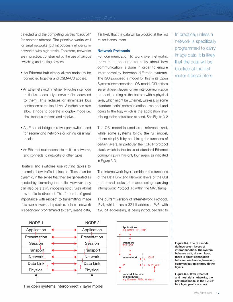
Network ProtocolsFor communication to work over networks,
there must be some formality about how
communication is done in order to ensure
interoperability between different systems.
The ISO proposed a model for this in its Open
Systems Interconnection - OSI model. OSI defines
seven different layers for any intercommunication
protocol, starting at the bottom with a physical
layer, which might be Ethernet, wireless, or some
standard serial communications method and
going to the top, which is the application layer
relating to the actual task at hand. See Figure 3-2
The OSI model is used as a reference and,
while some systems follow the full model,
others simplify it by combining the functions of
certain layers. In particular the TCP/IP protocol
stack which is the basis of standard Ethernet
communication, has only four layers, as indicated
in Figure 3-3.
The Internetwork layer combines the functions
of the Data Link and Network layers of the OSI
model and looks after addressing, carrying
Internetwork Protocol (IP) within the MAC frame.
The current version of Internetwork Protocol,
IPv4, which uses a 32 bit address. IPv6, with
128 bit addressing, is being introduced first to
In practice, unless a network is specifically programmed to carry image data, it is likely that the data will be blocked at the first router it encounters.
Figure 3-2. The OSI model defines seven layers of interconnection. The system behaves as if, at each layer, there is direct connection between each node; however, communication is through the layers.
Figure 3-3. With Ethernet and most data networks, the preferred model is the TCP/IP four layer protocol stack.
18 Extron Streaming A/V over IP Design Guide
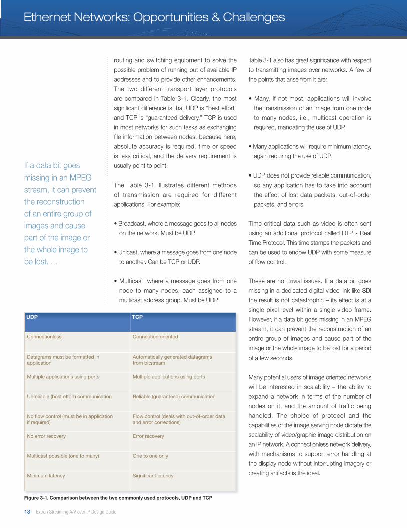
UDP TCP
Connectionless Connection oriented
Datagrams must be formatted in application
Automatically generated datagrams from bitstream
Multiple applications using ports Multiple applications using ports
Unreliable (best effort) communication Reliable (guaranteed) communication
No flow control (must be in application if required)
Flow control (deals with out-of-order data and error corrections)
No error recovery Error recovery
Multicast possible (one to many) One to one only
Minimum latency Significant latency
If a data bit goes missing in an MPEG stream, it can prevent the reconstruction of an entire group of images and cause part of the image or the whole image to be lost. . .
routing and switching equipment to solve the
possible problem of running out of available IP
addresses and to provide other enhancements.
The two different transport layer protocols
are compared in Table 3-1. Clearly, the most
significant difference is that UDP is “best effort”
and TCP is “guaranteed delivery.” TCP is used
in most networks for such tasks as exchanging
file information between nodes, because here,
absolute accuracy is required, time or speed
is less critical, and the delivery requirement is
usually point to point.
The Table 3-1 illustrates different methods
of transmission are required for different
applications. For example:
• Broadcast, where a message goes to all nodes
on the network. Must be UDP.
• Unicast, where a message goes from one node
to another. Can be TCP or UDP.
• Multicast, where a message goes from one
node to many nodes, each assigned to a
multicast address group. Must be UDP.
Table 3-1 also has great significance with respect
to transmitting images over networks. A few of
the points that arise from it are:
• Many, if not most, applications will involve
the transmission of an image from one node
to many nodes, i.e., multicast operation is
required, mandating the use of UDP.
• Many applications will require minimum latency,
again requiring the use of UDP.
• UDP does not provide reliable communication,
so any application has to take into account
the effect of lost data packets, out-of-order
packets, and errors.
Time critical data such as video is often sent
using an additional protocol called RTP - Real
Time Protocol. This time stamps the packets and
can be used to endow UDP with some measure
of flow control.
These are not trivial issues. If a data bit goes
missing in a dedicated digital video link like SDI
the result is not catastrophic – its effect is at a
single pixel level within a single video frame.
However, if a data bit goes missing in an MPEG
stream, it can prevent the reconstruction of an
entire group of images and cause part of the
image or the whole image to be lost for a period
of a few seconds.
Many potential users of image oriented networks
will be interested in scalability – the ability to
expand a network in terms of the number of
nodes on it, and the amount of traffic being
handled. The choice of protocol and the
capabilities of the image serving node dictate the
scalability of video/graphic image distribution on
an IP network. A connectionless network delivery,
with mechanisms to support error handling at
the display node without interrupting imagery or
creating artifacts is the ideal.
Figure 3-1. Comparison between the two commonly used protocols, UDP and TCP
Ethernet Networks: Opportunities & Challenges

www.extron.com 19
Intelligent, Programmable Network Switching and Routing Commonly used enterprise network switching
products can provide very high backbone
bandwidth or “switched fabric” capacity. They
offer the capability to program or learn rules for
efficient routing and switching of network traffic.
These products are referred to as managed,
intelligent switches with Layer 3 – 4 abilities. A
summary of the capabilities available from these
switches is presented below:
• Switched fabric bandwidth for managed routing
and switching equipment can range from
10 Gbps to over 400 Gbps.
• Static routing tables can be programmed,
preventing certain types of traffic from reaching
areas of a network based on the origination or
destination address as well as traffic type, e.g.,
voice, data, and video.
• Dynamic routing tables can be automatically
developed and “learned” by the switches
over time as they work to efficiently distribute
packets across multiple switches or router
hops.
• Redundancy can be designed into switched
networks. Multiple delivery paths ensure
packet delivery if faults are experienced.
• Spanning tree protocol and other methods exist
for preventing undesired loops and “flooding” of
traffic that could develop in architectures with
multiple routing points capable of forwarding
packets. Correct application and configuration
of spanning tree protocol is critical to avoiding
potential congestion or slowdowns. Incorrect
application of products using proprietary layer 3
protocols or standard virtual router redundancy
protocol VRRP, can contribute to unacceptable
network latency.
• Virtual LANs - VLANs, can be established by
segmenting specific capacity on the same
physical media to create different virtual
networks. Defined amounts of bandwidth can
be set aside for different groups of VLANs
based on user groups, IP addresses, or traffic
type. An example of this would be splitting
capacity of a network equally between voice,
data, and video traffic.
• Multicast support ensures that only a single
layer of bandwidth is distributed across the
network per image source, regardless of the
location or number of destinations subscribing
to it. Network traffic is pruned, or removed,
from segments of the network where it is not
required. IGMP snooping, supported in Layer
3 and some Layer 2 switches is one method
used to ensure nodes connected to switches
are not flooded with unnecessary traffic.
Selecting multicast for video transport is
arguably the most important decision to
make. Multicast reduces overall bandwidth
requirements and provides the fastest method
for transporting unrepeatable real-time data,
such as video and voice while ensuring
low latencies. TCP transport is valuable for
applications where less reliable, low bandwidth
connections exist or applications where data
can be repeated and re-requested.
Oversubscription of Layer 2, 3 & 4 switches must
be avoided when transporting video over IP.
Oversubscription or congestion can cause large
swings in latency, which could inhibit support of
reliable video service. The capacity and features
of managed, Layer 3 – 4 intelligent switching
Figure 3-4. Form factor of a 48-port ethernet switch
A connectionless network delivery, with mechanisms to support error handling at the display node without interrupting imagery or creating artifacts, is the ideal.
20 Extron Streaming A/V over IP Design Guide
The ideal is clearly an arrangement in which the overhead for dealing with errors is minimized. The ideal system is resilient in the face of variable error rates, and it does not introduce significant latency.
provides the potential to support distribution of
a large number of real-time, video and graphic
images on an enterprise network. Layer 3 – 4
switches are available that require little or no
programming expertise.
The Challenges of Compressing and Streaming A/V on IP NetworksIt is clear that the IP networks provide great
promise for convenience, scalability, and cost
advantages in A/V systems. The packet-based
delivery used by networks is a means by which
reliable performance can be achieved. However,
in practice, there are some challenges that result
from using the IP network delivery mechanism.
These have been overcome, but they are
important to understand:
UDP - User Datagram Protocol multicast
transmission is used to minimize latency and
to allow multiple end points. This can result in
unreliable delivery, and separate steps must be
taken to eliminate the effects of errors.
• The actual performance of a network
connection cannot be predicted.
• The overhead needed to correct for errors is
difficult to predict. The tendency then may be
to over-correct.
• Over-correction leads to increased latency and
inefficient use of bandwidth. Not only that, there
may still be network conditions that result in
complete loss of image.
• The ideal is an arrangement in which the
overhead for dealing with errors is minimized.
The ideal system is resilient in the face of
unpredictable and variable error rates, and
does not introduce significant latency. In
addition, the system should work over a wide
range of bit rates.
Compression must be used to reduce the
amount of data transmitted because for both
technical and economic reasons most practical
networks do not have the bandwidth to carry
uncompressed images.
Transmission errors are remarkably rare within
a well-structured Ethernet installation that is
working below full capacity. It is feasible to
transmit video over such networks without any
special precautions, provided that the video
stream itself represents only a small proportion of
the network traffic.
However, as soon as there is traffic between
different network segments and different network
types, the likelihood of errors increases. This
is especially true when public networks are
involved, and, here, the Quality of Service - QoS
of such networks is currently defined in ITU
Recommendation Y.1541, “Network performance
objectives for IP-based services.”
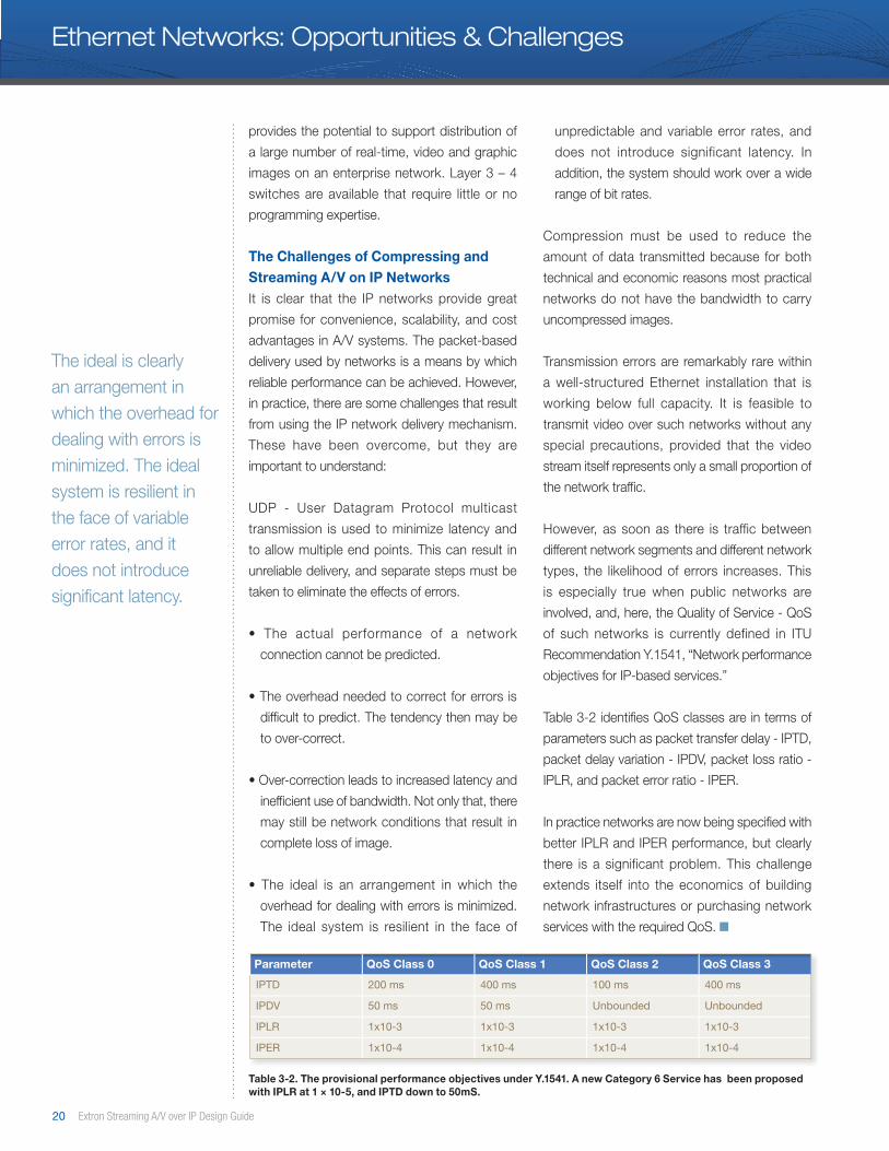
Table 3-2 identifies QoS classes are in terms of
parameters such as packet transfer delay - IPTD,
packet delay variation - IPDV, packet loss ratio -
IPLR, and packet error ratio - IPER.
In practice networks are now being specified with
better IPLR and IPER performance, but clearly
there is a significant problem. This challenge
extends itself into the economics of building
network infrastructures or purchasing network
services with the required QoS. ■
Table 3-2. The provisional performance objectives under Y.1541. A new Category 6 Service has been proposed with IPLR at 1 × 10⁻⁵, and IPTD down to 50mS.
Parameter QoS Class 0 QoS Class 1 QoS Class 2 QoS Class 3
IPTD 200 ms 400 ms 100 ms 400 ms
IPDV 50 ms 50 ms Unbounded Unbounded
IPLR 1x10⁻³ 1x10⁻³ 1x10⁻³ 1x10⁻³
IPER 1x10⁻⁴ 1x10⁻⁴ 1x10⁻⁴ 1x10⁻⁴
Ethernet Networks: Opportunities & Challenges
www.extron.com 21
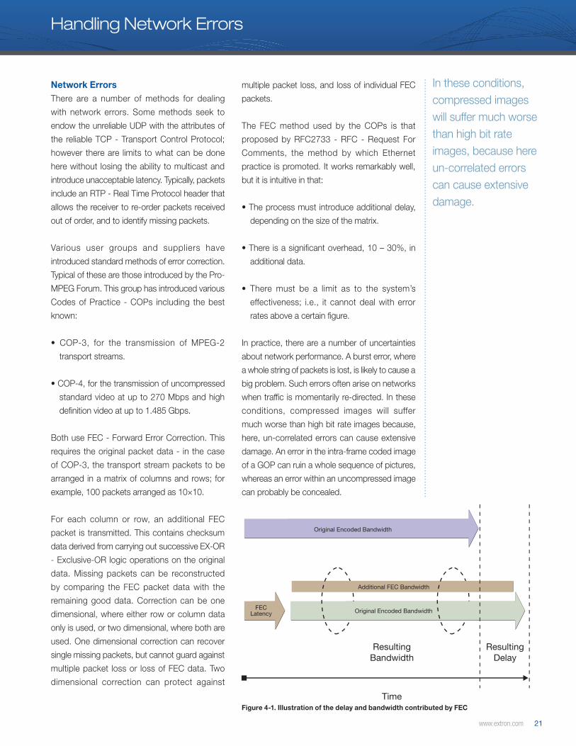
Time
ResultingDelay
ResultingBandwidth
Original Encoded Bandwidth
Original Encoded BandwidthFECLatency
Additional FEC Bandwidth
Handling Network Errors
Figure 4-1. Illustration of the delay and bandwidth contributed by FEC
Network Errors There are a number of methods for dealing
with network errors. Some methods seek to
endow the unreliable UDP with the attributes of
the reliable TCP - Transport Control Protocol;
however there are limits to what can be done
here without losing the ability to multicast and
introduce unacceptable latency. Typically, packets
include an RTP - Real Time Protocol header that
allows the receiver to re-order packets received
out of order, and to identify missing packets.
Various user groups and suppliers have
introduced standard methods of error correction.
Typical of these are those introduced by the Pro-
MPEG Forum. This group has introduced various
Codes of Practice - COPs including the best
known:
• COP-3, for the transmission of MPEG-2
transport streams.
• COP-4, for the transmission of uncompressed
standard video at up to 270 Mbps and high
definition video at up to 1.485 Gbps.
Both use FEC - Forward Error Correction. This
requires the original packet data - in the case
of COP-3, the transport stream packets to be
arranged in a matrix of columns and rows; for
example, 100 packets arranged as 10×10.
For each column or row, an additional FEC
packet is transmitted. This contains checksum
data derived from carrying out successive EX-OR
- Exclusive-OR logic operations on the original
data. Missing packets can be reconstructed
by comparing the FEC packet data with the
remaining good data. Correction can be one
dimensional, where either row or column data
only is used, or two dimensional, where both are
used. One dimensional correction can recover
single missing packets, but cannot guard against
multiple packet loss or loss of FEC data. Two
dimensional correction can protect against
multiple packet loss, and loss of individual FEC
packets.
The FEC method used by the COPs is that
proposed by RFC2733 - RFC - Request For
Comments, the method by which Ethernet
practice is promoted. It works remarkably well,
but it is intuitive in that:
• The process must introduce additional delay,
depending on the size of the matrix.
• There is a significant overhead, 10 – 30%, in
additional data.
• There must be a limit as to the system’s
effectiveness; i.e., it cannot deal with error
rates above a certain figure.
In practice, there are a number of uncertainties
about network performance. A burst error, where
a whole string of packets is lost, is likely to cause a
big problem. Such errors often arise on networks
when traffic is momentarily re-directed. In these
conditions, compressed images will suffer
much worse than high bit rate images because,
here, un-correlated errors can cause extensive
damage. An error in the intra-frame coded image
of a GOP can ruin a whole sequence of pictures,
whereas an error within an uncompressed image
can probably be concealed.
In these conditions, compressed images will suffer much worse than high bit rate images, because here un-correlated errors can cause extensive damage.
22 Extron Streaming A/V over IP Design Guide
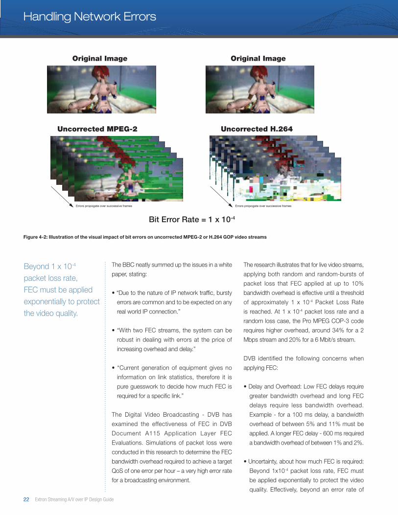
Beyond 1 x 10⁻⁴ packet loss rate, FEC must be applied exponentially to protect the video quality.
Errors propogate over successive frames Errors propogate over successive frames
Uncorrected MPEG-2 Uncorrected H.264
Bit Error Rate = 1 x 10⁻⁴
Original Image Original Image
Figure 4-2: Illustration of the visual impact of bit errors on uncorrected MPEG-2 or H.264 GOP video streams
The BBC neatly summed up the issues in a white
paper, stating:
• “Due to the nature of IP network traffic, bursty
errors are common and to be expected on any
real world IP connection.”
• “With two FEC streams, the system can be
robust in dealing with errors at the price of
increasing overhead and delay.”
• “Current generation of equipment gives no
information on link statistics, therefore it is
pure guesswork to decide how much FEC is
required for a specific link.”
The Digital Video Broadcasting - DVB has
examined the effectiveness of FEC in DVB
Document A115 Application Layer FEC
Evaluations. Simulations of packet loss were
conducted in this research to determine the FEC
bandwidth overhead required to achieve a target
QoS of one error per hour – a very high error rate
for a broadcasting environment.
The research illustrates that for live video streams,
applying both random and random-bursts of
packet loss that FEC applied at up to 10%
bandwidth overhead is effective until a threshold
of approximately 1 x 10⁻⁴ Packet Loss Rate
is reached. At 1 x 10⁻⁴ packet loss rate and a
random loss case, the Pro MPEG COP-3 code
requires higher overhead, around 34% for a 2
Mbps stream and 20% for a 6 Mbit/s stream.
DVB identified the following concerns when
applying FEC:
• Delay and Overhead: Low FEC delays require
greater bandwidth overhead and long FEC
delays require less bandwidth overhead.
Example - for a 100 ms delay, a bandwidth
overhead of between 5% and 11% must be
applied. A longer FEC delay - 600 ms required
a bandwidth overhead of between 1% and 2%.
• Uncertainty, about how much FEC is required:
Beyond 1x10⁻⁴ packet loss rate, FEC must
be applied exponentially to protect the video
quality. Effectively, beyond an error rate of
Handling Network Errors
www.extron.com 23
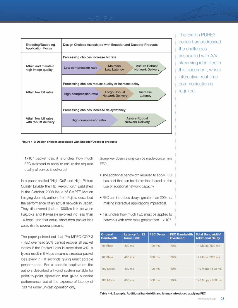
Processing choices increase delay/latency
Processing choices reduce quality or increase delay
Processing choices increase bit rate
High compression ratio
High compression ratio
Assure RobustNetwork Delivery
Assure RobustNetwork DeliveryLow compression ratioAttain and maintain
high image quality
Encoding/DecodingApplication Focus
Design Choices Associated with Encoder and Decoder Products
Attain low bit rateswith robust delivery
Attain low bit rates
MaintainLow Latency
Forgo RobustNetwork Delivery
IncreaseLatency
1x10⁻⁴ packet loss, it is unclear how much
FEC overhead to apply to ensure the required
quality of service is delivered.
In a paper entitled “High QoS and High Picture
Quality Enable the HD Revolution,” published
in the October 2008 issue of SMPTE Motion
Imaging Journal, authors from Fujitsu described
the performance of an actual network in Japan.
They discovered that a 1000km link between
Fukuoka and Kawasaki involved no less than
14 hops, and that actual short term packet loss
could rise to several percent.
The paper pointed out that Pro-MPEG COP-3
- FEC overhead 20% cannot recover all packet
losses if the Packet Loss is more than 4%. A
typical result in 8 Mbps stream is a residual packet
loss every 7 - 8 seconds giving unacceptable
performance. For a specific application the
authors described a hybrid system suitable for
point-to-point operation that gives superior
performance, but at the expense of latency of
700 ms under unicast operation only.
Some key observations can be made concerning
FEC:
• The additional bandwidth required to apply FEC
has cost that can be determined based on the
use of additional network capacity.
• FEC can introduce delays greater than 200 ms,
making interactive applications impractical.
• It is unclear how much FEC must be applied to
networks with error rates greater than 1 x 10⁻⁴.
Figure 4-3: Design choices associated with Encoder/Decoder products
The Extron PURE3 codec has addressed the challenges associated with A/V streaming identified in this document, where interactive, real-time communication is required.
Table 4-1. Example: Additional bandwidth and latency introduced applying FEC
Original Bandwidth
Latency for 12frame GOP
FEC Delay FEC BandwidthOverhead
Total Bandwidth/Additional Delay
10 Mbps 400 ms 100 ms 40% 14 Mbps / 500 ms
10 Mbps 400 ms 500 ms 20% 12 Mbps / 900 ms
100 Mbps 400 ms 100 ms 40% 140 Mbps / 500 ms
100 Mbps 400 ms 500 ms 20% 120 Mbps / 900 ms
24 Extron Streaming A/V over IP Design Guide
• Uncertainty concerning the effectiveness of FEC
applied to video streams grows as the number
of router hops on a delivery path increase.
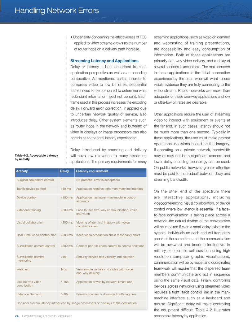
Streaming Latency and ApplicationsDelay or latency is best described from an
application perspective as well as an encoding
perspective. As mentioned earlier, in order to
compress video to low bit rates, sequential
frames need to be compared to determine what
redundant information need not be sent. Each
frame used in this process increases the encoding
delay. Forward error correction, if applied due
to uncertain network quality of service, also
introduces delay. Other system elements such
as router hops in the network and buffering of
video in displays or image processors can also
contribute to the total latency experienced.
Delay introduced by encoding and delivery
will have low relevance to many streaming
applications. The primary requirements for many
streaming applications, such as video on demand
and webcasting of training presentations,
are accessibility and easy consumption of
information. Both of these applications are
primarily one-way video delivery, and a delay of
several seconds is acceptable. The main concern
in these applications is the initial connection
experience by the user, who will want to see
visible evidence they are truly connecting to the
video stream. Public networks are more than
adequate for these one-way applications and low
or ultra-low bit rates are desirable.
Other applications require the user of streaming
video to interact with equipment or events at
the far end. In such cases, latency should not
be much more than one second. Typically in
these applications, the user must make prompt
operational decisions based on the imagery.
If operating on a private network, bandwidth
may or may not be a significant concern and
lower delay encoding technology can be used.
On public networks, however, greater attention
must be paid to the tradeoff between delay and
streaming bandwidth.
On the other end of the spectrum there
are interact ive appl icat ions, including
videoconferencing, visual collaboration, or device
control where low latency is essential. If a face-
to-face conversation is taking place across a
network, the natural rhythm of the conversation
will be impaired if even a small delay exists in the
system. Individuals on each end will frequently
speak at the same time and the communication
will be awkward and become ineffective. In
military or scientific collaboration using high
resolution computer graphic visualizations,
communication will be by voice, and coordinated
teamwork will require that the dispersed team
members communicate and act in sequence
using the same visual data. Finally, controlling
devices across networks using streamed video
requires a tight, tacit control link in the man-
machine interface such as a keyboard and
mouse. Significant delay will make controlling
the equipment difficult. Table 4-2 Illustrates
acceptable latency by application.
Handling Network Errors
Activity Delay Latency requirement
Surgical equipment control 0 No potential error is acceptable
Tactile device control <50 ms Application requires tight man-machine interface
Device control <100 ms Application has lower man-machine control accuracy
Videoconfrencing <200 ms Face to face two-way communication, voice and video
Visual collaboration <200 ms Viewing of identical imagery with voice communication
Real-Time video contribution <500 ms Keep video production chain reasonably short
Surveillance camera control <500 ms Camera pan-tilt-zoom control to coarse positions
Surveillance camera monitoring
<1s Security service has visibility into situation
Webcast 1-5s View simple visuals and slides with voice, one-way delivery
Low bit rate video contribution
5-10s Application driven by network limitations
Video on Demand 5-10s Primary concern is download buffering time
Consider system latency introduced by image processors or displays at the destination .
Table 4-2. Acceptable Latencyby Activity
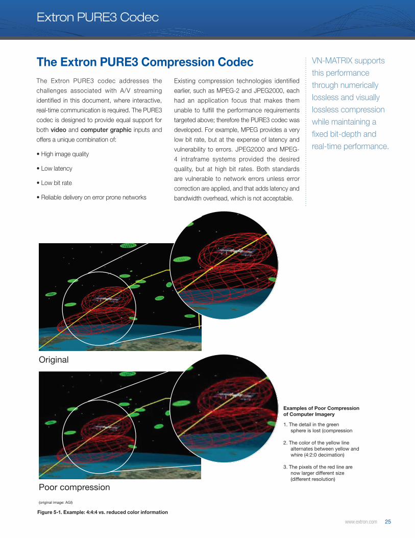
www.extron.com 25
Original
Poor compression
1. The detail in the greensphere is lost (compression
2. The color of the yellow linealternates between yellow andwhire (4:2:0 decimation)
3. The pixels of the red line arenow larger different size(different resolution)
Examples of Poor Compressionof Computer Imagery
(original image: AGI)
The Extron PURE3 Compression Codec
Extron PURE3 Codec
VN-MATRIX supports this performance through numerically lossless and visually lossless compression while maintaining a fixed bit-depth and real-time performance.
Figure 5-1. Example: 4:4:4 vs. reduced color information
The Extron PURE3 codec addresses the
challenges associated with A/V streaming
identified in this document, where interactive,
real-time communication is required. The PURE3
codec is designed to provide equal support for
both video and computer graphic inputs and
offers a unique combination of:
• High image quality
• Low latency
• Low bit rate
• Reliable delivery on error prone networks
Existing compression technologies identified
earlier, such as MPEG-2 and JPEG2000, each
had an application focus that makes them
unable to fulfill the performance requirements
targeted above; therefore the PURE3 codec was
developed. For example, MPEG provides a very
low bit rate, but at the expense of latency and
vulnerability to errors. JPEG2000 and MPEG-
4 intraframe systems provided the desired
quality, but at high bit rates. Both standards
are vulnerable to network errors unless error
correction are applied, and that adds latency and
bandwidth overhead, which is not acceptable.
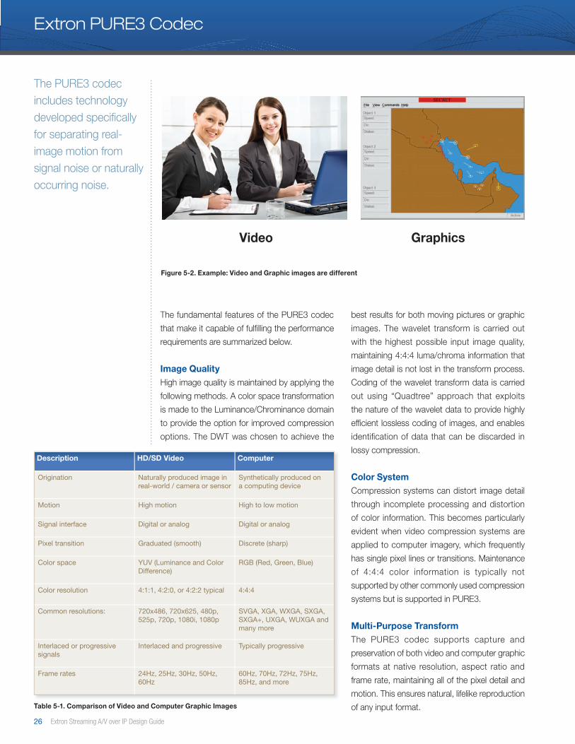
26 Extron Streaming A/V over IP Design Guide
Extron PURE3 Codec
The fundamental features of the PURE3 codec
that make it capable of fulfilling the performance
requirements are summarized below.
Image QualityHigh image quality is maintained by applying the
following methods. A color space transformation
is made to the Luminance/Chrominance domain
to provide the option for improved compression
options. The DWT was chosen to achieve the
best results for both moving pictures or graphic
images. The wavelet transform is carried out
with the highest possible input image quality,
maintaining 4:4:4 luma/chroma information that
image detail is not lost in the transform process.
Coding of the wavelet transform data is carried
out using “Quadtree” approach that exploits
the nature of the wavelet data to provide highly
efficient lossless coding of images, and enables
identification of data that can be discarded in
lossy compression.
Color SystemCompression systems can distort image detail
through incomplete processing and distortion
of color information. This becomes particularly
evident when video compression systems are
applied to computer imagery, which frequently
has single pixel lines or transitions. Maintenance
of 4:4:4 color information is typically not
supported by other commonly used compression
systems but is supported in PURE3.
Multi-Purpose TransformThe PURE3 codec supports capture and
preservation of both video and computer graphic
formats at native resolution, aspect ratio and
frame rate, maintaining all of the pixel detail and
motion. This ensures natural, lifelike reproduction
of any input format.
Description HD/SD Video Computer
Origination Naturally produced image in real-world / camera or sensor
Synthetically produced on a computing device
Motion High motion High to low motion
Signal interface Digital or analog Digital or analog
Pixel transition Graduated (smooth) Discrete (sharp)
Color space YUV (Luminance and Color Difference)
RGB (Red, Green, Blue)
Color resolution 4:1:1, 4:2:0, or 4:2:2 typical 4:4:4
Common resolutions: 720x486, 720x625, 480p, 525p, 720p, 1080i, 1080p
SVGA, XGA, WXGA, SXGA, SXGA+, UXGA, WUXGA and many more
Interlaced or progressive signals
Interlaced and progressive Typically progressive
Frame rates 24Hz, 25Hz, 30Hz, 50Hz, 60Hz
60Hz, 70Hz, 72Hz, 75Hz, 85Hz, and more
Table 5-1. Comparison of Video and Computer Graphic Images
The PURE3 codec includes technology developed specifically for separating real-image motion from signal noise or naturally occurring noise.
Figure 5-2. Example: Video and Graphic images are different
Video Graphics
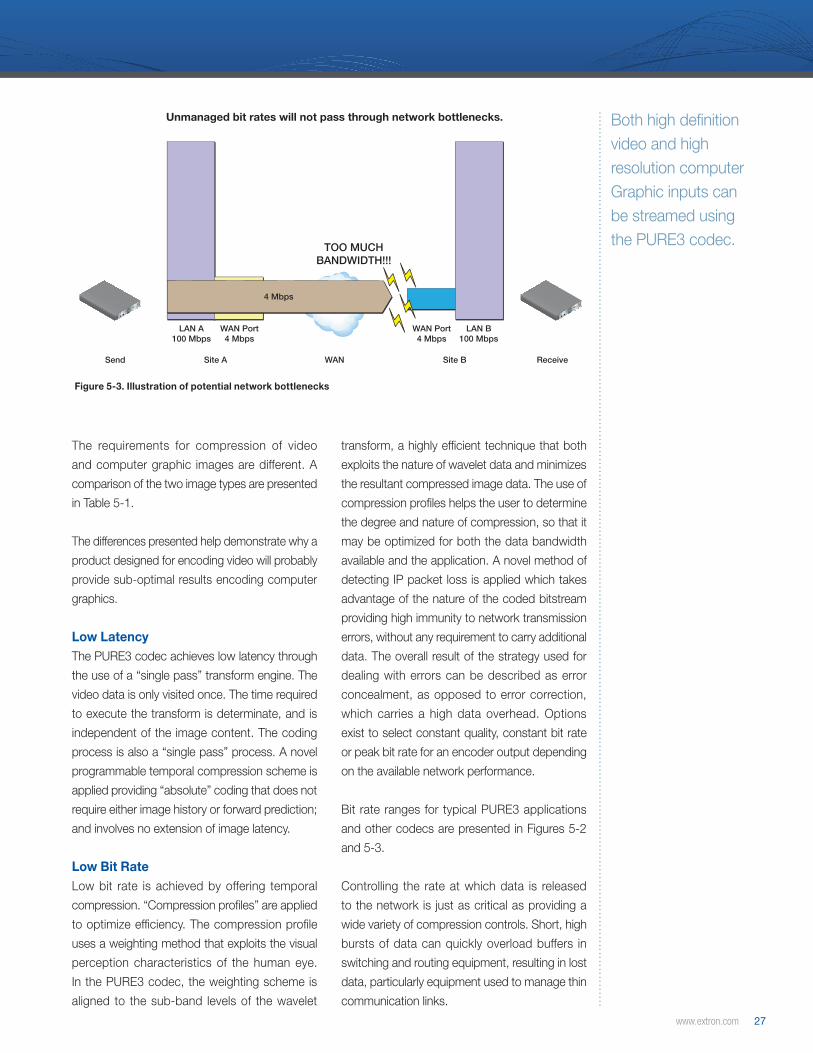
www.extron.com 27
Unmanaged bit rates will not pass through network bottlenecks.
LAN A100 Mbps
LAN B100 Mbps
WAN Port4 Mbps
WAN Port4 Mbps
Send Site A Site B ReceiveWAN
TOO MUCHBANDWIDTH!!!
4 Mbps
12V DC
REG
6A MAX
COM 1
OUT
IN
LOOP
COM 2
12V DC
REG
6A MAX
COM 1
OUT
IN
LOOP
COM 2
Streaming bit rates must be tightly managed to pass from sender to receiver.
LAN A100 Mbps
LAN B100 Mbps
WAN Port4 Mbps
WAN Port4 Mbps
Send Site A Site B ReceiveWAN
2 Mbps
12V DC
REG
6A MAX
COM 1
OUT
IN
LOOP
COM 2
12V DC
REG
6A MAX
COM 1
OUT
IN
LOOP
COM 2
Both high definition video and high resolution computer Graphic inputs can be streamed using the PURE3 codec.
The requirements for compression of video
and computer graphic images are different. A
comparison of the two image types are presented
in Table 5-1.
The differences presented help demonstrate why a
product designed for encoding video will probably
provide sub-optimal results encoding computer
graphics.
Low LatencyThe PURE3 codec achieves low latency through
the use of a “single pass” transform engine. The
video data is only visited once. The time required
to execute the transform is determinate, and is
independent of the image content. The coding
process is also a “single pass” process. A novel
programmable temporal compression scheme is
applied providing “absolute” coding that does not
require either image history or forward prediction;
and involves no extension of image latency.
Low Bit RateLow bit rate is achieved by offering temporal
compression. “Compression profiles” are applied
to optimize efficiency. The compression profile
uses a weighting method that exploits the visual
perception characteristics of the human eye.
In the PURE3 codec, the weighting scheme is
aligned to the sub-band levels of the wavelet
transform, a highly efficient technique that both
exploits the nature of wavelet data and minimizes
the resultant compressed image data. The use of
compression profiles helps the user to determine
the degree and nature of compression, so that it
may be optimized for both the data bandwidth
available and the application. A novel method of
detecting IP packet loss is applied which takes
advantage of the nature of the coded bitstream
providing high immunity to network transmission
errors, without any requirement to carry additional
data. The overall result of the strategy used for
dealing with errors can be described as error
concealment, as opposed to error correction,
which carries a high data overhead. Options
exist to select constant quality, constant bit rate
or peak bit rate for an encoder output depending
on the available network performance.
Bit rate ranges for typical PURE3 applications
and other codecs are presented in Figures 5-2
and 5-3.
Controlling the rate at which data is released
to the network is just as critical as providing a
wide variety of compression controls. Short, high
bursts of data can quickly overload buffers in
switching and routing equipment, resulting in lost
data, particularly equipment used to manage thin
communication links.
Figure 5-3. Illustration of potential network bottlenecks
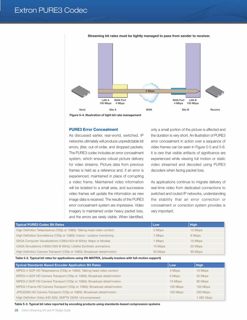
28 Extron Streaming A/V over IP Design Guide
Unmanaged bit rates will not pass through network bottlenecks.
LAN A100 Mbps
LAN B100 Mbps
WAN Port4 Mbps
WAN Port4 Mbps
Send Site A Site B ReceiveWAN
TOO MUCHBANDWIDTH!!!
4 Mbps
12V DC
REG
6A MAX
COM 1
OUT
IN
LOOP
COM 2
12V DC
REG
6A MAX
COM 1
OUT
IN
LOOP
COM 2
Streaming bit rates must be tightly managed to pass from sender to receiver.
LAN A100 Mbps
LAN B100 Mbps
WAN Port4 Mbps
WAN Port4 Mbps
Send Site A Site B ReceiveWAN
2 Mbps
12V DC
REG
6A MAX
COM 1
OUT
IN
LOOP
COM 2
12V DC
REG
6A MAX
COM 1
OUT
IN
LOOP
COM 2
PURE3 Error ConcealmentAs discussed earlier, real-world, switched, IP
networks ultimately will produce unpredictable bit
errors, jitter, out-of-order, and dropped packets.
The PURE3 codec includes an error concealment
system, which ensures robust picture delivery
for video streams. Picture data from previous
frames is held as a reference and, if an error is
experienced, maintained in place of corrupting
a video frame. Maintained video information
will be isolated to a small area, and successive
video frames will update the information as new
image data is received. The results of the PURE3
error concealment system are impressive. Video
imagery is maintained under heavy packet loss,
and the errors are rarely visible. When identified,
only a small portion of the picture is affected and
the duration is very short. An illustration of PURE3
error concealment in action over a sequence of
video frames can be seen in Figure 5-5 and 5-6.
It is rare that visible artifacts of significance are
experienced while viewing full motion or static
video streamed and decoded using PURE3
decoders when facing packet loss.
As applications continue to migrate delivery of
real-time video from dedicated connections to
switched and routed IP networks, understanding
the stability that an error correction or
concealment or correction system provides is
very important.
Extron PURE3 Codec
Tyoical Standards Based Encoder Application Bit Rates Low High
MPEG-4 GOP HD Telepresence (720p or 1080i): Talking head video content 3 Mbps 10 Mbps
MPEG-4 GOP HD Camera Transport (720p or 1080i): Broadcast detail/motion 6 Mbps 25 Mbps
MPEG-2 GOP HD Camera Transport (720p or 1080i): Broadcast detail/motion 15 Mbps 80 Mbps
MPEG I-Frame HD Camera Transport (720p or 1080i): Broadcast detail/motion 100 Mbps 150 Mbps
JPEG2000 HD Camera Transport (720p or 1080i): Broadcast detail/motion 100 Mbps 200 Mbps
High Definition Video (HD-SDI), SMPTE 292M: Uncompressed - 1 .485 Gbps
Table 5-3. Typical bit rates reported by encoding products using standards-based compression systems
Typical PURE3 Codec Bit Rates Low High
High Definition Telepresence (720p or 1080i): Talking head video content 5 Mbps 15 Mbps
High Definition Surveillance (720p or 1080i): Indoor / outdoor monitoring 1 Mbps 6 Mbps
SXGA Computer Visualizations (1280x1024 @ 60Hz): Maps or Models 1 Mbps 15 Mbps
UXGA Simulations (1600x1200 @ 60Hz): Lifelike Synthetic animations 15 Mbps 25 Mbps
High Definition Camera Transport (720p or 1080i), Broadcast detail/motion 50 Mbps 90 Mbps
Table 5-2. Typical bit rates for applications using VN-MATRIX, (visually lossless with full-motion support)
Figure 5-4. Illustration of tight bit rate management
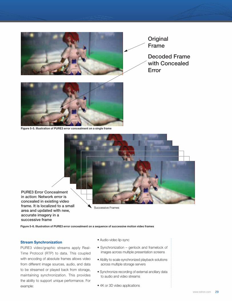
www.extron.com 29
OriginalFrame
Decoded Framewith ConcealedError
PURE3 Error Concealmentin action: Network error isconcealed in existing videoframe. It is localized to a smallarea and updated with new,accurate imagery in asuccessive frame
Successive Frames
OriginalFrame
Decoded Framewith ConcealedError
PURE3 Error Concealmentin action: Network error isconcealed in existing videoframe. It is localized to a smallarea and updated with new,accurate imagery in asuccessive frame
Successive Frames
Figure 5-5. Illustration of PURE3 error concealment on a single frame
Figure 5-6. Illustration of PURE3 error concealment on a sequence of successive motion video frames
Stream SynchronizationPURE3 video/graphic streams apply Real-
Time Protocol (RTP) to data. This coupled
with encoding of absolute frames allows video
from different image sources, audio, and data
to be streamed or played back from storage,
maintaining synchronization. This provides
the ability to support unique performance. For
example:
• Audio-video lip-sync
• Synchronization – genlock and framelock of images across multiple presentation screens
• Ability to scale synchronized playback solutions across multiple storage servers
• Synchronize recording of external ancillary data to audio and video streams
• 4K or 3D video applications
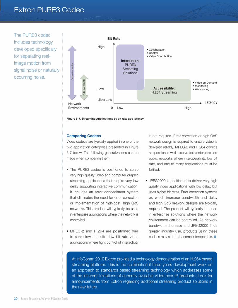
30 Extron Streaming A/V over IP Design Guide
Comparing CodecsVideo codecs are typically applied in one of the
two application categories presented in Figure
5-7 below. The following generalizations can be
made when comparing them.
• The PURE3 codec is positioned to serve
very high quality video and computer graphic
streaming applications that require very low
delay supporting interactive communication.
It includes an error concealment system
that eliminates the need for error correction
or implementation of high-cost, high QoS
networks. This product will typically be used
in enterprise applications where the network is
controlled.
• MPEG-2 and H.264 are positioned well
to serve low and ultra-low bit rate video
applications where tight control of interactivity
is not required. Error correction or high QoS
network design is required to ensure video is
delivered reliably. MPEG-2 and H.264 codecs
are positioned well to serve both enterprise and
public networks where interoperability, low bit
rate, and one-to-many applications must be
fulfilled.
• JPEG2000 is positioned to deliver very high
quality video applications with low delay, but
uses higher bit rates. Error correction systems
or, which increase bandwidth and delay
and high QoS network designs are typically
required. The product will typically be used
in enterprise solutions where the network
environment can be controlled. As network
bandwidths increase and JPEG2000 finds
greater industry use, products using these
codecs may start to become interoperable. ■
Figure 5-7. Streaming Applications by bit rate abd latency
Extron PURE3 Codec
The PURE3 codec includes technology developed specifically for separating real-image motion from signal noise or naturally occurring noise.
Interaction:PURE3
StreamingSolutions
Accessibility:H.264 Streaming
Bit Rate
High• Collaboration• Control• Video Contribution
• Video on Demand • Monitoring• Webcasting
Ultra LowLatency
Low
LowNetwork Environments 0 High
Extron Streaming Solutions
Priv
ate
netw
orks
Pub
lic o
r P
rivat
e
At InfoComm 2010 Extron provided a technology demonstration of an H.264 based streaming platform. This is the culmination if three years development work on an approach to standards based streaming technology which addresses some of the inherent limitations of currently available video over IP products. Look for announcements from Extron regarding additional streaming product solutions in the near future.
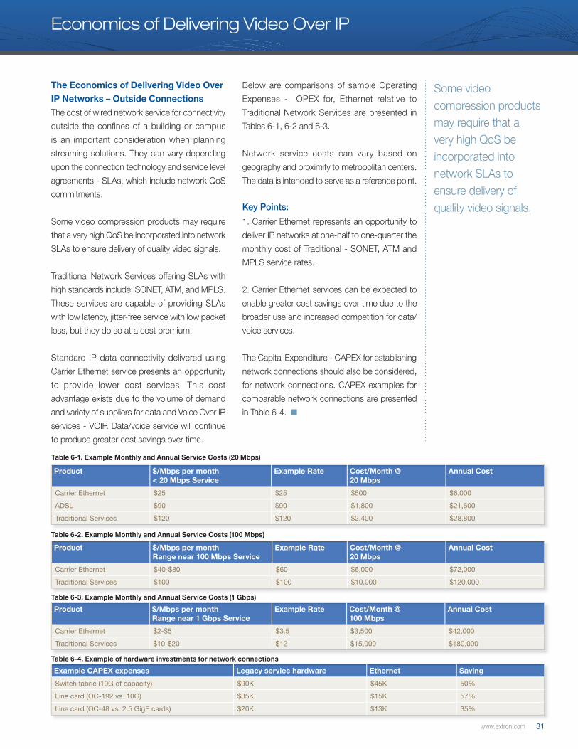
www.extron.com 31
The Economics of Delivering Video Over IP Networks – Outside ConnectionsThe cost of wired network service for connectivity
outside the confines of a building or campus
is an important consideration when planning
streaming solutions. They can vary depending
upon the connection technology and service level
agreements - SLAs, which include network QoS
commitments.
Some video compression products may require
that a very high QoS be incorporated into network
SLAs to ensure delivery of quality video signals.
Traditional Network Services offering SLAs with
high standards include: SONET, ATM, and MPLS.
These services are capable of providing SLAs
with low latency, jitter-free service with low packet
loss, but they do so at a cost premium.
Standard IP data connectivity delivered using
Carrier Ethernet service presents an opportunity
to provide lower cost services. This cost
advantage exists due to the volume of demand
and variety of suppliers for data and Voice Over IP
services - VOIP. Data/voice service will continue
to produce greater cost savings over time.
Below are comparisons of sample Operating
Expenses - OPEX for, Ethernet relative to
Traditional Network Services are presented in
Tables 6-1, 6-2 and 6-3.
Network service costs can vary based on
geography and proximity to metropolitan centers.
The data is intended to serve as a reference point.
Key Points:
1. Carrier Ethernet represents an opportunity to
deliver IP networks at one-half to one-quarter the
monthly cost of Traditional - SONET, ATM and
MPLS service rates.
2. Carrier Ethernet services can be expected to
enable greater cost savings over time due to the
broader use and increased competition for data/
voice services.
The Capital Expenditure - CAPEX for establishing
network connections should also be considered,
for network connections. CAPEX examples for
comparable network connections are presented
in Table 6-4. ■
Table 6-1. Example Monthly and Annual Service Costs (20 Mbps)
Table 6-2. Example Monthly and Annual Service Costs (100 Mbps)
Table 6-3. Example Monthly and Annual Service Costs (1 Gbps)
Table 6-4. Example of hardware investments for network connections
Product $/Mbps per month< 20 Mbps Service
Example Rate Cost/Month @20 Mbps
Annual Cost
Carrier Ethernet $25 $25 $500 $6,000
ADSL $90 $90 $1,800 $21,600
Traditional Services $120 $120 $2,400 $28,800
Product $/Mbps per monthRange near 100 Mbps Service
Example Rate Cost/Month @20 Mbps
Annual Cost
Carrier Ethernet $40-$80 $60 $6,000 $72,000
Traditional Services $100 $100 $10,000 $120,000
Example CAPEX expenses Legacy service hardware Ethernet Saving
Switch fabric (10G of capacity) $90K $45K 50%
Line card (OC-192 vs . 10G) $35K $15K 57%
Line card (OC-48 vs . 2 .5 GigE cards) $20K $13K 35%
Product $/Mbps per monthRange near 1 Gbps Service
Example Rate Cost/Month @100 Mbps
Annual Cost
Carrier Ethernet $2-$5 $3 .5 $3,500 $42,000
Traditional Services $10-$20 $12 $15,000 $180,000
Economics of Delivering Video Over IP
Some video compression products may require that a very high QoS be incorporated into network SLAs to ensure delivery of quality video signals.

32 Extron Streaming A/V over IP Design Guide
Notes

www.extron.com 33
Streaming System DesignsWhere IS Extron A/V Streaming Over IP Used?Extron solutions for streaming A/V over IP are ideally suited for
governmental, corporate, medical, industrial, and entertainment
applications that require streaming and playback of high quality
images. Low delay delivery makes Extron A/V streaming ideal for
interactive and control applications over IP networks, including:
Command and Control - Collaboration
Studio to Studio Video Contribution
Post Production Collaboration, Content
Review and Color Grading
House of Worship
Enterprise Collaboration
Remote Control of Real Time Video Production
Equipment
Control Rooms: For broadcast, surveillance, command and
control, and monitoring
Medical, Contribution & Collaboration: For broadcast, post-
production, scientific, military, product design, and oil and gas
Training, Education and Documentation: For real-time
visualization and simulation environments
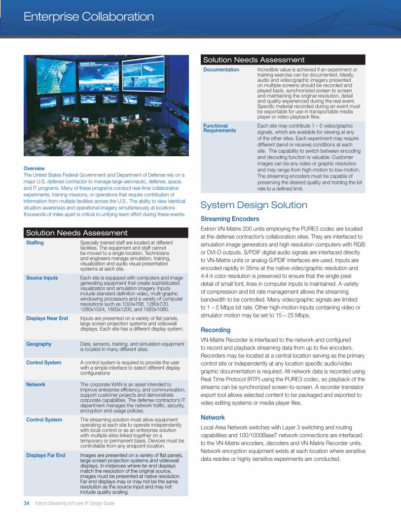
34 Extron Streaming A/V over IP Design Guide
Enterprise Collaboration
Solution Needs AssessmentStaffing Specially trained staff are located at different
facilities. The equipment and staff cannot be moved to a single location. Technicians and engineers manage simulation, training, visualization and audio visual presentation systems at each site.
Source Inputs Each site is equipped with computers and image generating equipment that create sophisticated visualization and simulation imagery. Inputs include standard definition video, multi-graphic windowing processors and a variety of computer resolutions such as 1024x768, 1280x720, 1280x1024, 1600x1200, and 1920x1080.
Displays Near End Inputs are presented on a variety of flat panels, large screen projection systems and videowall displays. Each site has a different display system.
Geography Data, sensors, training, and simulation equipment is located in many different sites.
Control System A control system is required to provide the user with a simple interface to select different display configurations
Network The corporate WAN is an asset intended to improve enterprise efficiency, and communication, support customer projects and demonstrate corporate capabilities. The defense contractor’s IT department manages the network traffic, security, encryption and usage policies.
Control System The streaming solution must allow equipment operating at each site to operate independently with local control or as an enterprise solution with multiple sites linked together on a temporary or permanent basis. Devices must be controllable from any endpoint location.
Displays Far End Images are presented on a variety of flat panels, large screen projection systems and videowall displays. In instances where far end displays match the resolution of the original source, images must be presented at native resolution. Far end displays may or may not be the same resolution as the source input and may not include quality scaling.
OverviewThe United States Federal Government and Department of Defense rely on a major U.S. defense contractor to manage large aeronautic, defense, space, and IT programs. Many of these programs conduct real-time collaborative experiments, training missions, or operations that require contribution of information from multiple facilities across the U.S.. The ability to view identical situation awareness and operational imagery simultaneously at locations thousands of miles apart is critical to unifying team effort during these events.
System Design SolutionStreaming Encoders
Extron VN-Matrix 200 units employing the PURE3 codec are located at the defense contractor’s collaboration sites. They are interfaced to simulation image generators and high resolution computers with RGB or DVI-D outputs. S/PDIF digital audio signals are interfaced directly to VN-Matrix units or analog-S/PDIF interfaces are used. Inputs are encoded rapidly in 35ms at the native video/graphic resolution and 4:4:4 color resolution is preserved to ensure that the single pixel detail of small font, lines in computer inputs is maintained. A variety of compression and bit rate management allows the streaming bandwidth to be controlled. Many video/graphic signals are limited to 1 – 5 Mbps bit rate. Other high-motion inputs containing video or simulator motion may be set to 15 – 25 Mbps.
Recording
VN-Matrix Recorder is interfaced to the network and configured to record and playback streaming data from up to five encoders. Recorders may be located at a central location serving as the primary control site or independently at any location specific audio/video graphic documentation is required. All network data is recorded using Real Time Protocol (RTP) using the PURE3 codec, so playback of the streams can be synchronized screen-to-screen. A recorder translator export tool allows selected content to be packaged and exported to video editing systems or media player files.
Network
Local Area Network switches with Layer 3 switching and routing capabilities and 100/1000BaseT network connections are interfaced to the VN-Matrix encoders, decoders and VN-Matrix Recorder units. Network encryption equipment exists at each location where sensitive data resides or highly sensitive experiments are conducted.
Solution Needs AssessmentDocumentation Incredible value is achieved if an experiment or
training exercise can be documented. Ideally, audio and video/graphic imagery presented on multiple screens should be recorded and played back, synchronized screen to screen and maintaining the original resolution, detail and quality experienced during the real event. Specific material recorded during an event must be exportable for use in transportable media player or video playback files.
Functional Requirements
Each site may contribute 1 – 5 video/graphic signals, which are available for viewing at any of the other sites. Each experiment may require different (send or receive) conditions at each site. The capability to switch between encoding and decoding function is valuable. Customer images can be any video or graphic resolution and may range from high-motion to low-motion. The streaming encoders must be capable of preserving the desired quality and holding the bit rate to a defined limit.
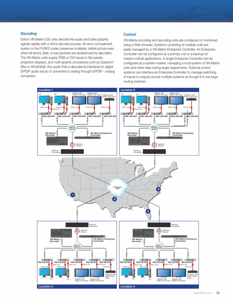
www.extron.com 35
12V DCREG
6A MAX I
IN
OUT
DIGITALAUDIO II
COM 1
OUTPCPERIPH IN
COM 2
DVI-IDVI-I
12V DCREG
6A MAX I
IN
OUT
DIGITALAUDIO II
COM 1
OUTPCPERIPH IN
COM 2
DVI-IDVI-I
12V DCREG
6A MAX I
IN
OUT
DIGITALAUDIO II
COM 1
OUTPCPERIPH IN
COM 2
DVI-IDVI-I
12V DCREG
6A MAX I
IN
OUT
DIGITALAUDIO II
COM 1
OUTPCPERIPH IN
COM 2
DVI-IDVI-I
12V DCREG
6A MAX I
IN
OUT
DIGITALAUDIO II
COM 1
OUTPCPERIPH IN
COM 2
DVI-IDVI-I
12V DCREG
6A MAX I
IN
OUT
DIGITALAUDIO II
COM 1
OUTPCPERIPH IN
COM 2
DVI-IDVI-I
12V DCREG
6A MAX I
IN
OUT
DIGITALAUDIO II
COM 1
OUTPCPERIPH IN
COM 2
DVI-IDVI-I
12V DCREG
6A MAX I
IN
OUT
DIGITALAUDIO II
COM 1
OUTPCPERIPH IN
COM 2
DVI-IDVI-I
12V DCREG
6A MAX I
IN
OUT
DIGITALAUDIO II
COM 1
OUTPCPERIPH IN
COM 2
DVI-IDVI-I
12V DCREG
6A MAX I
IN
OUT
DIGITALAUDIO II
COM 1
OUTPCPERIPH IN
COM 2
DVI-IDVI-I
12V DCREG
6A MAX I
IN
OUT
DIGITALAUDIO II
COM 1
OUTPCPERIPH IN
COM 2
DVI-IDVI-I
12V DCREG
6A MAX I
IN
OUT
DIGITALAUDIO II
COM 1
OUTPCPERIPH IN
COM 2
DVI-IDVI-I
12V DCREG
6A MAX I
IN
OUT
DIGITALAUDIO II
COM 1
OUTPCPERIPH IN
COM 2
DVI-IDVI-I
12V DCREG
6A MAX I
IN
OUT
DIGITALAUDIO II
COM 1
OUTPCPERIPH IN
COM 2
DVI-IDVI-I
12V DCREG
6A MAX I
IN
OUT
DIGITALAUDIO II
COM 1
OUTPCPERIPH IN
COM 2
DVI-IDVI-I
12V DCREG
6A MAX I
IN
OUT
DIGITALAUDIO II
COM 1
OUTPCPERIPH IN
COM 2
DVI-IDVI-I
12V DCREG
6A MAX I
IN
OUT
DIGITALAUDIO II
COM 1
OUTPCPERIPH IN
COM 2
DVI-IDVI-I
12V DCREG
6A MAX I
IN
OUT
DIGITALAUDIO II
COM 1
OUTPCPERIPH IN
COM 2
DVI-IDVI-I
12V DCREG
6A MAX I
IN
OUT
DIGITALAUDIO II
COM 1
OUTPCPERIPH IN
COM 2
DVI-IDVI-I
12V DCREG
6A MAX I
IN
OUT
DIGITALAUDIO II
COM 1
OUTPCPERIPH IN
COM 2
DVI-IDVI-I
VN-Matrix EnterpriseController
VN-Matrix Recorder
Network Encryption
Network Router
VNC 200 DVI VNC 200 DVI VNC 200 DVI VNC 200 DVI VNC 200 DVI
Display with RGB or DVI InputPC PC
Display with RGB or DVI Input Projector with
RGB or DVI Input
RGB or DVIRGB or DVI
RGB or DVI RGB or DVI RGB or DVI RGB or DVI
Location 1
VN-Matrix EnterpriseController
VN-Matrix Recorder
Network Encryption
Network Router
VNC 200 DVI VNC 200 DVI VNC 200 DVI VNC 200 DVI VNC 200 DVI
Display with RGB or DVI InputPC PC
Display with RGB or DVI Input Projector with
RGB or DVI Input
RGB or DVIRGB or DVI
RGB or DVI RGB or DVI RGB or DVI RGB or DVI
Location 2
VN-Matrix EnterpriseController
VN-Matrix Recorder
Network Encryption
Network Router
VNC 200 DVI VNC 200 DVI VNC 200 DVI VNC 200 DVI VNC 200 DVI
Display with RGB or DVI Input
PC PC Display with RGB or DVI Input
Projector with RGB or DVI Input
RGB or DVIRGB or DVI
RGB or DVIRGB or DVI RGB or DVI RGB or DVI
RGB or DVI
Location 4
Layer 3NetworkSwitch
Layer 3NetworkSwitch
Layer 3NetworkSwitch
VN-Matrix EnterpriseController
VN-Matrix Recorder
Network Encryption
Network Router
VNC 200 DVI VNC 200 DVI VNC 200 DVI VNC 200 DVI VNC 200 DVI
Display with RGB or DVI Input
PC PC Display with RGB or DVI Input
Projector with RGB or DVI Input
RGB or DVIRGB or DVI
RGB or DVIRGB or DVI RGB or DVI RGB or DVI
RGB or DVI
Location 3
1
Layer 3NetworkSwitch
EnterpriseWAN 2
4
3
Decoding
Extron VN-Matrix 200 units decode the audio and video/graphic signals rapidly with a 35ms decode process. An error concealment system in the PURE3 codec preserves a reliable, stable picture even when bit errors, jitter, or lost packets are experienced by decoders. The VN-Matrix units supply RGB or DVI inputs to flat panels, projection displays, and multi-graphic processors such as Quantum Elite or WindoWall. Any audio that is decoded is interfaced to digital S/PDIF audio inputs or converted to analog through S/PDIF – analog converters.
Control
VN-Matrix encoding and decoding units are configured or monitored using a Web browser. Systems consisting of multiple units are easily managed by a VN-Matrix Enterprise Controller. An Enterprise Controller can be configured as a primary unit or a backup for mission-critical applications. A single Enterprise Controller can be configured as a system master, managing a local system of VN-Matrix units and other sites during larger experiments. External control systems can interface an Enterprise Controller to manage switching of inputs to outputs across multiple systems as though it is one large routing switcher.
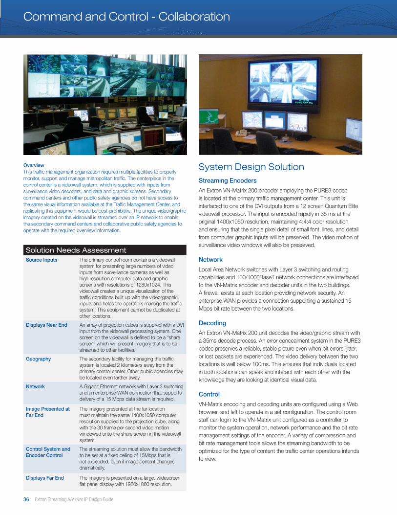
36 Extron Streaming A/V over IP Design Guide
Command and Control - Collaboration
Solution Needs AssessmentSource Inputs The primary control room contains a videowall
system for presenting large numbers of video inputs from surveillance cameras as well as high resolution computer data and graphic screens with resolutions of 1280x1024. This videowall creates a unique visualization of the traffic conditions built up with the video/graphic inputs and helps the operators manage the traffic system. This equipment cannot be duplicated at other locations.
Displays Near End An array of projection cubes is supplied with a DVI input from the videowall processing system. One screen on the videowall is defined to be a “share screen” which will present imagery that is to be streamed to other facilities.
Geography The secondary facility for managing the traffic system is located 2 kilometers away from the primary control center. Other public agencies may be located even farther away.
Network A Gigabit Ethernet network with Layer 3 switching and an enterprise WAN connection that supports delivery of a 15 Mbps data stream is required.
Image Presented at Far End
The imagery presented at the far location must maintain the same 1400x1050 computer resolution supplied to the projection cube, along with the 30 frame per second video motion windowed onto the share screen in the videowall system.
Control System and Encoder Control
The streaming solution must allow the bandwidth to be set at a fixed ceiling of 15Mbps that is not exceeded, even if image content changes dramatically.
Displays Far End The imagery is presented on a large, widescreen flat panel display with 1920x1080 resolution.
System Design SolutionStreaming Encoders
An Extron VN-Matrix 200 encoder employing the PURE3 codec is located at the primary traffic management center. This unit is interfaced to one of the DVI outputs from a 12 screen Quantum Elite videowall processor. The input is encoded rapidly in 35 ms at the original 1400x1050 resolution, maintaining 4:4:4 color resolution and ensuring that the single pixel detail of small font, lines, and detail from computer graphic inputs will be preserved. The video motion of surveillance video windows will also be preserved.
Network
Local Area Network switches with Layer 3 switching and routing capabilities and 100/1000BaseT network connections are interfaced to the VN-Matrix encoder and decoder units in the two buildings. A firewall exists at each location providing network security. An enterprise WAN provides a connection supporting a sustained 15 Mbps bit rate between the two locations.
Decoding
An Extron VN-Matrix 200 unit decodes the video/graphic stream with a 35ms decode process. An error concealment system in the PURE3 codec preserves a reliable, stable picture even when bit errors, jitter, or lost packets are experienced. The video delivery between the two locations is well below 100ms. This ensures that individuals located in both locations can speak and interact with each other with the knowledge they are looking at identical visual data.
Control
VN-Matrix encoding and decoding units are configured using a Web browser, and left to operate in a set configuration. The control room staff can login to the VN-Matrix unit configured as a controller to monitor the system operation, network performance and the bit rate management settings of the encoder. A variety of compression and bit rate management tools allows the streaming bandwidth to be optimized for the type of content the traffic center operations intends to view.
OverviewThis traffic management organization requires multiple facilities to properly monitor, support and manage metropolitan traffic. The centerpiece in the control center is a videowall system, which is supplied with inputs from surveillance video decoders, and data and graphic screens. Secondary command centers and other public safety agencies do not have access to the same visual information available at the Traffic Management Center, and replicating this equipment would be cost-prohibitive. The unique video/graphic imagery created on the videowall is streamed over an IP network to enable the secondary command centers and collaborative public safety agencies to operate with the required overview information.
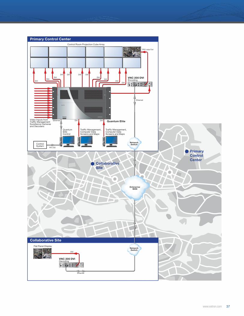
www.extron.com 37
12V DCREG
6A MAX I
IN
OUT
DIGITALAUDIO II
COM 1
OUTPCPERIPH IN
COM 2
DVI-IDVI-I
12V DCREG
6A MAX I
IN
OUT
DIGITALAUDIO II
COM 1
OUTPCPERIPH IN
COM 2
DVI-IDVI-I
POWER
QUANTUM ELITE
DATA
Extron
Primary Control Center
Primary Control Center
Collaborative Site
Collaborative Site
Video Inputs from Traf�c Management Sureillance Cameras and Decoders
Flat Panel Display
Control Room Projection Cube Array
Traf�c Management, Computer Data Screens and Maps
Traf�c Management, Computer Data Screens and Maps
Quantum EliteControl
RS-232
Ethernet
Ethernet
Ethernet
DVI DVI
DVIDVI
DVI
DVI DVI DVI DVI
DVI
DVI
DVIDVI
DVI
DVI Loop Out
Control System
VNC 200 DVIEncoding
VNC 200 DVIDecoding
Quantum Elite
NetworkSwitch
NetworkSwitch
EnterpriseWAN
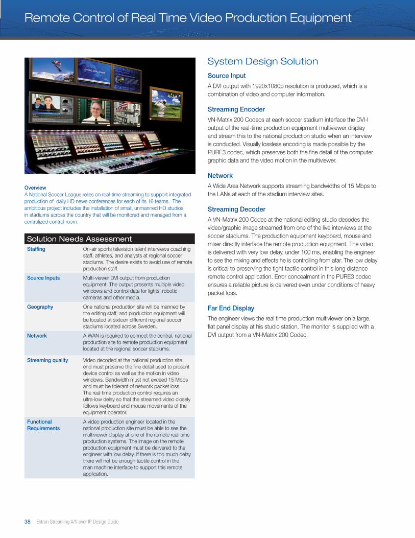
38 Extron Streaming A/V over IP Design Guide
Remote Control of Real Time Video Production Equipment
Solution Needs AssessmentStaffing On-air sports television talent interviews coaching
staff, athletes, and analysts at regional soccer stadiums. The desire exists to avoid use of remote production staff.
Source Inputs Multi-viewer DVI output from production equipment. The output presents multiple video windows and control data for lights, robotic cameras and other media.
Geography One national production site will be manned by the editing staff, and production equipment will be located at sixteen different regional soccer stadiums located across Sweden.
Network A WAN is required to connect the central, national production site to remote production equipment located at the regional soccer stadiums.
Streaming quality Video decoded at the national production site end must preserve the fine detail used to present device control as well as the motion in video windows. Bandwidth must not exceed 15 Mbps and must be tolerant of network packet loss. The real time production control requires an ultra-low delay so that the streamed video closely follows keyboard and mouse movements of the equipment operator.
Functional Requirements
A video production engineer located in the national production site must be able to see the multiviewer display at one of the remote real-time production systems. The image on the remote production equipment must be delivered to the engineer with low delay. If there is too much delay there will not be enough tactile control in the man machine interface to support this remote application.
System Design SolutionSource Input
A DVI output with 1920x1080p resolution is produced, which is a combination of video and computer information.
Streaming Encoder
VN-Matrix 200 Codecs at each soccer stadium interface the DVI-I output of the real-time production equipment multiviewer display and stream this to the national production studio when an interview is conducted. Visually lossless encoding is made possible by the PURE3 codec, which preserves both the fine detail of the computer graphic data and the video motion in the multiviewer.
Network
A Wide Area Network supports streaming bandwidths of 15 Mbps to the LANs at each of the stadium interview sites.
Streaming Decoder
A VN-Matrix 200 Codec at the national editing studio decodes the video/graphic image streamed from one of the live interviews at the soccer stadiums. The production equipment keyboard, mouse and mixer directly interface the remote production equipment. The video is delivered with very low delay, under 100 ms, enabling the engineer to see the mixing and effects he is controlling from afar. The low delay is critical to preserving the tight tactile control in this long distance remote control application. Error concealment in the PURE3 codec ensures a reliable picture is delivered even under conditions of heavy packet loss.
Far End Display
The engineer views the real time production multiviewer on a large, flat panel display at his studio station. The monitor is supplied with a DVI output from a VN-Matrix 200 Codec.
OverviewA National Soccer League relies on real-time streaming to support integrated production of daily HD news conferences for each of its 16 teams. The ambitious project includes the installation of small, unmanned HD studios in stadiums across the country that will be monitored and managed from a centralized control room.

www.extron.com 39
1
2
3
456
7
8109
1112
1314
15
16
12V DC
REG
6A MAX
I
IN
OUT
DIGITAL
AUDIO
II
COM 1
OUT
PC
PERIPH
IN
COM 2
DVI-I
DVI-I
12V DC
REG
6A MAX
I
IN
OUT
DIGITAL
AUDIO
II
COM 1
OUT
PC
PERIPH
IN
COM 2
DVI-I
DVI-I
12V DC
REG
6A MAX
I
IN
OUT
DIGITAL
AUDIO
II
COM 1
OUT
PC
PERIPH
IN
COM 2
DVI-I
DVI-I
H
COMMUN
ICATION
Tx
COMMUN
ICATION
Tx
H
COMMUN
ICATION
Tx
COMMUN
ICATION
Tx
H
COMMUN
ICATION
Tx
COMMUN
ICATION
Tx
Stadium 1
EnterpriseWAN
Remote SiteEditing Equipment
LAN
Central Control
Central Control RemoteEditing Equipment
LAN
Stadium 16
Stadium 15
Stadium 14
Stadium 13
Stadium 12
Stadium 11
Stadium 10
Stadium 9
Stadium 8
Stadium 7
Stadium 6
Stadium 5
Stadium 4
Stadium 3
Stadium 2
Extron VNE 200 DVIVN-Matrix Codec DVI
DVI
Ethernet
DVI
Remote SiteEditing Equipment
To WAN
LAN
Extron VNE 200 DVIVN-Matrix Codec DVI
DVI
Ethernet
Ethernet
Ethernet
DVI
Extron VND 200 DVIVN-Matrix Codec DVI
DVI
Encoding
Encoding Decoding
Remote Control of Real Time Video Production Equipment

40 Extron Streaming A/V over IP Design Guide
Studio – Studio Video Contribution
Solution Needs AssessmentSource Inputs A traffic news presenter from a virtual studio
is chroma-keyed over live traffic maps and surveillance video overlays in a special purpose production facility. The produced output is SDI video with embedded audio.
Geography The broadcaster purchasing the traffic service is located across the country.
Network A cost-effective, secure network connection supporting up to 20 Mbps bandwidth is required from the traffic news service provider to the regional broadcaster.
Production Input A broadcast production studio will accept a serial digital video input with embedded audio into a real-time television production environment.
Control System The network bandwidth must be managed within a maximum bandwidth limit on a DSL connection.
Functional Requirements
Real-time production in the broadcast environment requires that the original 10 Bit video resolution and 4:2:2 color depth be preserved. Event sequencing and interaction is required between the on-air talent in both locations, and low latency video delivery is required to make a natural interaction possible. The DSL connection will not guarantee 100% packet delivery, so the streaming solution must maintain a stable picture and reliable picture quality, even under packet loss.
System Design SolutionSource Input
Broadcast production equipment supplies video traffic news coverage including on-air talent chroma-keyed over traffic condition maps and traffic surveillance feeds. An SDI video signal with 10 bit video depth, embedded audio, and 4:2:2 color resolution is the output signal.
Streaming Video Encoders
Extron VN-Matrix 300 units employing the PURE3 codec interface the video production equipment. SDI with embedded audio is encoded with low, 35ms delay and the encoder preserves the 10 Bit, 4:2:2 color information contained in the serial digital video signal, maintaining unique, editable video frames. The VN-Matrix 300 Codec is interfaced to a Local Area Network to deliver the audio/video streams. A variety of compression and bit rate controls exist to allow delivery of the best picture given the available network bandwidth. The combined video and four channels of embedded audio is capped at 15 Mbps.
Network
A Local Area Network switch with 100BaseT network connections is interfaced to the VN-Matrix 300 encoder. VPN routers at each studio are interfaced to a DSL network connection with 20 Mbps capacity. The VPN routers maintain security of the VN-Matrix 300 encoders as the video is delivered over a public network.
Streaming Video Decoders
Extron VN-Matrix 300 units decode the audio and video signals rapidly with a 35ms decode process. Audio and video are synchronized and the low delay of the total encode to decode path ensures that the individuals at both sites can speak with each other naturally and events can be coordinated between sites. An error concealment system in the PURE3 codec preserves a reliable, stable picture even when bit errors, jitter, or lost packets are experienced across the public network infrastructure. Visually lossless image compression by the VN-Matrix 300 encoders preserve the 10 bit video depth and 4:2:2 color resolution, providing a video signal input consisting of absolute video frames that are editable with the receiving studio equipment.
OverviewVideo contributed to live sports, news or event broadcasts has historically required dedicated point-to-point fiber, satellite or microwave connections. Frequently this type of connection is impractical or a more cost effective connection is required. Video delivered to the studio is desired to maintain the highest qualities so that a quality production can be prepared before it is broadcasted to consumers. This project reviews Live Traffic Analysis delivered from an outsourced studio to regional television broadcasters.

www.extron.com 41
12V DCREG
6A MAX
COM 1
OUT IN LOOP
COM 2
12V DCREG
6A MAX
COM 1
OUT IN LOOP
COM 2
12V DCREG
6A MAX
COM 1
OUT IN LOOP
COM 2
H
COMMUN
ICATION
Tx
COMMUN
ICATION
Tx
H
COMMUN
ICATION
Tx
COMMUN
ICATION
Tx
Layer 3NetworkSwitch
Layer 3NetworkSwitch
Camera
Ethernet
Production Studio
Production Studio
Broadcast Studio 1
Broadcast Studio 1
VND 300 SDI Decoding
VNC 300 SDI Encoding
SDI
SDI
EnterpriseWAN
Production System EquipmentEthernet Layer 3
NetworkSwitch
Broadcast Studio 2
Broadcast Studio 2
VND 300 SDI Decoding SDI
Production System EquipmentEthernet

42 Extron Streaming A/V over IP Design Guide
Post Production Collaboration, Content Review, and Color Grading
Solution Needs AssessmentWork Flow Creative staff in the production facility have
prepared the video or animation material and are prepared to play back the material for review. Account staff at the presentation suite manage the customer discussion and review workflow.
Source Inputs Video or animation production equipment located in the studio output HD-SDI video with embedded audio.
Geography The production staff and customer review facility may be located at opposite ends of a state or, continent or across the globe.
Network Network switches supporting Layer 3 switching in the local area networks and an enterprise WAN will connect the two facilities. Sustained bandwidth of 100 Mbps is required through the full connection path to support streaming of the video at full fidelity.
Control System The encoders and decoders must be configured to operate within defined bit rates when in use.
Functional Requirements
A very low delay must be maintained so that as individuals are discussing and working at each location, they are both referring to identical material. IP networks do not guarantee 100% packet delivery, so the streaming solution must maintain a stable picture, with reliable picture quality, even under heavy packet loss.
System Design SolutionSource Input
Video production equipment is used to prepare and play back high definition video content with embedded audio, which is output and presented on accurate-color HD-SDI flat panel displays. The displays are capable of presenting 10 bit video resolution and 4:2:2 color resolution. The monitors are frequently color corrected to ensure the truest color is presented.
Streaming Video Encoders
Extron VN-Matrix 300 units employing the PURE3 codec interface the video production equipment. HD-SDI with embedded audio is encoded with low, 35ms delay and the encoder preserves the 10 Bit, 4:2:2 color information contained in the serial digital video signal, critical to preserving the image quality that will be delivered to the far location. The VN-Matrix 300 Codec is interfaced to a local area network to deliver the audio/video streams. A variety of compression and bit rate controls exist to allow delivery of the best picture given the available network bandwidth.
Network
Professional, local area network switches with Layer 3 switching and routing capabilities and 1000BaseT network connections are interfaced to the VN-Matrix encoder. A firewall exists at each location and an enterprise WAN ensures that the HD video can be delivered with a sustained throughput of 100 Mbps. Network bandwidth for HD video may range from 50 to 90 Mbps and a block of 4 audio channels will require 16 Mbps. SD video may require 15 to 20 Mbps and a block of four uncompressed audio signals will require 8 Mbps.
Streaming Video Decoders
Extron VN-Matrix 300 units decode the audio and video signals rapidly with a 35ms decode process. Audio and video are synchronized and the low delay of the total encode to decode path ensures that when individuals at both sites discuss the material, they are both referring to the same piece of content. An error concealment system in the PURE3 codec preserves a reliable, stable picture even when bit errors, jitter, or lost packets are experienced on the network. Visually lossless image compression by the VN-Matrix 300 encoders preserve the 10 bit video depth and 4:2:2 color resolution. The post production color grading application in particular is very sensitive to preserving the color quality of the original signal.
Displays
HD-SDI flat panels are positioned at the far end Video Production review suite. The monitors are capable of presenting a full 10 bit color depth and are color corrected to ensure accurate reproduction of the decoded video signal.
OverviewOrganizations offering highly skilled production and animation services often have facilities located great distances from each other. Many times, customers are often not located in the same region where the creative work is prepared. This streaming solution allows the account management and customer to review creative work that has been prepared at locations a great distance away. Work is carried out collaboratively in real time; the customer and production company complete work quicker and more efficiently than before.
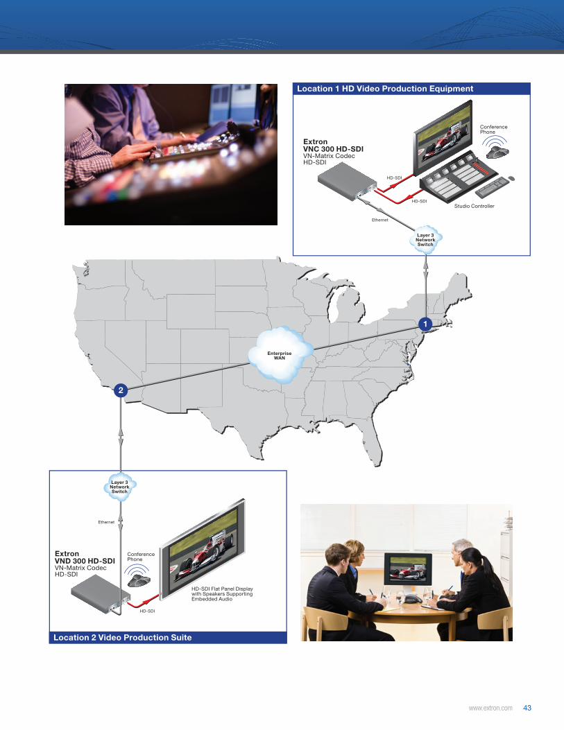
www.extron.com 43
12V DC
REG
6A MAX
COM 1
OUT
IN
LOOP
COM 2
12V DC
REG
6A MAX
COM 1
OUT
IN
LOOP
COM 2
H
COMMUN
ICATION
Tx
COMMUN
ICATION
Tx
Location 1 HD Video Production Equipment
Location 2 Video Production Suite
1
2
Layer 3NetworkSwitch
Layer 3NetworkSwitch
EnterpriseWAN
HD-SDI Flat Panel Display with Speakers Supporting Embedded Audio
Conference Phone
Conference Phone
HD-SDI
HD-SDI
HD-SDI
Ethernet
Ethernet
Extron VND 300 HD-SDI VN-Matrix Codec HD-SDI
Extron VNC 300 HD-SDI VN-Matrix Codec HD-SDI
Studio Controller
Post Production Collaboration, Content Review, and Color Grading
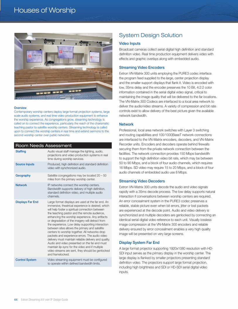
44 Extron Streaming A/V over IP Design Guide
Houses of Worship
Room Needs AssessmentStaffing Audio visual staff manage the lighting, audio,
projections and video production systems in real time during worship services.
Source Inputs Produced, high definition and standard definition video with synchronized audio.
Geography Satellite congregations may be located 20 – 50 miles from the primary worship center.
Network IP networks connect the worship centers. Bandwidth supports delivery of high definition, standard definition video, and multiple audio channels.
Displays Far End Large format displays are used at the far end. An immersive, theatrical experience is desired, which will help foster a spiritual connection between the teaching pastor and the remote audience, enhancing the worship experience. Any artifacts or degradation of the imagery will detract from the experience. Low delay supporting interaction between sites allows the primary and satellite centers to worship together. All networks drop packets and experience errors. The audio video delivery must maintain reliable delivery and quality. Audio and video presented on the far end must maintain lip-sync for the video and if multiple video streams are sent, they should be genlocked and framelocked.
Control System Video streaming equipment must be configured to operate within defined bandwidth limits.
System Design SolutionVideo Inputs
Broadcast cameras collect serial digital high definition and standard definition video. Real time production equipment delivers video with effects and graphic overlays along with embedded audio.
Streaming Video Encoders
Extron VN-Matrix 300 units employing the PURE3 codec interface the program feed supplied to the large, center projection display and the smaller support displays that flank it. Video is encoded with low, 35ms delay and the encoder preserves the 10 Bit, 4:2:2 color information contained in the serial digital video signal, critical to maintaining the image quality that will be delivered to the far locations. The VN-Matrix 300 Codecs are interfaced to a local area network to deliver the audio/video streams. A variety of compression and bit rate controls exist to allow delivery of the best picture given the available network bandwidth.
Network
Professional, local area network switches with Layer 3 switching and routing capabilities and 100/1000BaseT network connections are interfaced to the VN-Matrix encoders, decoders, and VN-Matrix Recorder units. Encoders and decoders operate behind firewalls securing them from the private network connection between the facilities. The network connection provides 150 Mbps bandwidth to support the high definition video bit rate, which may be between 50 to 90 Mbps, and a block of four audio channels, which requires 16 Mbps. SD video may require 15 to 20 Mbps, and a block of four audio channels of embedded audio use 8 Mbps.
Streaming Video Decoders
Extron VN-Matrix 300 units decode the audio and video signals rapidly with a 35ms decode process. The low delay supports natural interaction if conversations between worship centers are required. An error concealment system in the PURE3 codec preserves a reliable, stable picture even when bit errors, jitter or lost packets are experienced at the decode point. Audio and video delivery is synchronized and multiple decoders are genlocked by connecting an identical serial digital video reference to each unit. Visually lossless image compression at the VN-Matrix 300 encoders and reliable delivery ensured by error concealment enables a very high quality image will be presented on very large screens.
Display System Far End
A large format projector supporting 1920x1080 resolution with HD-SDI input serves as the primary display in the worship center. The large display is flanked by smaller projectors presenting standard definition video. The projectors support large format projection, including high brightness and SDI or HD-SDI serial digital video inputs.
OverviewContemporary worship centers deploy large format projection systems, large scale audio systems, and real time video production equipment to enhance the worship experience. As congregations grow, streaming technology is called on to connect the experience, particularly the reach of the charismatic teaching pastor to satellite worship centers. Streaming technology is called upon to connect the worship centers in real time and extend sermons to the second worship center over public networks.

www.extron.com 45
12V DCREG
6A MAX
COM 1
OUT IN LOOP
COM 2
12V DCREG
6A MAX
COM 1
OUT IN LOOP
COM 2
12V DCREG
6A MAX
COM 1
OUT IN LOOP
COM 2
12V DCREG
6A MAX
COM 1
OUT IN LOOP
COM 2
POWER
12V
0.4A MAX
OUTPUTS
INPUTSAudio De-embedder
RL
POWER
12V
0.4A MAX
OUTPUTS
INPUTS
1
2
3
4
MDA 4V HD-SDI
POWER12V .2A MAX
4
3
2
1
6
5
RES
ERVE
D
BLA
CK
BU
RS
T
BLACKBURST
COLORBARS-10
+4
1 2 3
ON
1 kHzAUDIO
BBG 6 A JBLACKBURST AND AUDIOGENERATOR
L R
H
COMMUN
ICATION
Tx
COMMUN
ICATION
Tx
Central Worship Center
Satellite Worship Center
Layer 3NetworkSwitch
Layer 3NetworkSwitch
EnterpriseWAN
VNC 300 HD-SDI Decoding
SDI Reference
Projector
Side Display
Side Display
Center Display
Projector
Projector
VNC 300 HD-SDI Decoding
VNC 300 HD-SDI Encoding
VNC 300 HD-SDI Encoding
HD-SDI or SDI
HD-SDI or SDI
HD-SDI or SDI
HD-SDI or SDI
HD-SDI or SDI
HD-SDI
HD Camera
SD or HD Camera
SD or HD Camera
SD or HD Camera
Real Time Video Mixing and Production System
SDI with Embedded Audio
Ethernet or Optical Ethernet
Ethernet or Optical Ethernet
Ethernet or Optical Ethernet
Ethernet or Optical Ethernet
House Audio
Ethernet or Optical Ethernet
Ethernet or Optical Ethernet
MDA 4V HD-SDI
Audio De-embedder

46 Extron Streaming A/V over IP Design Guide
Notes
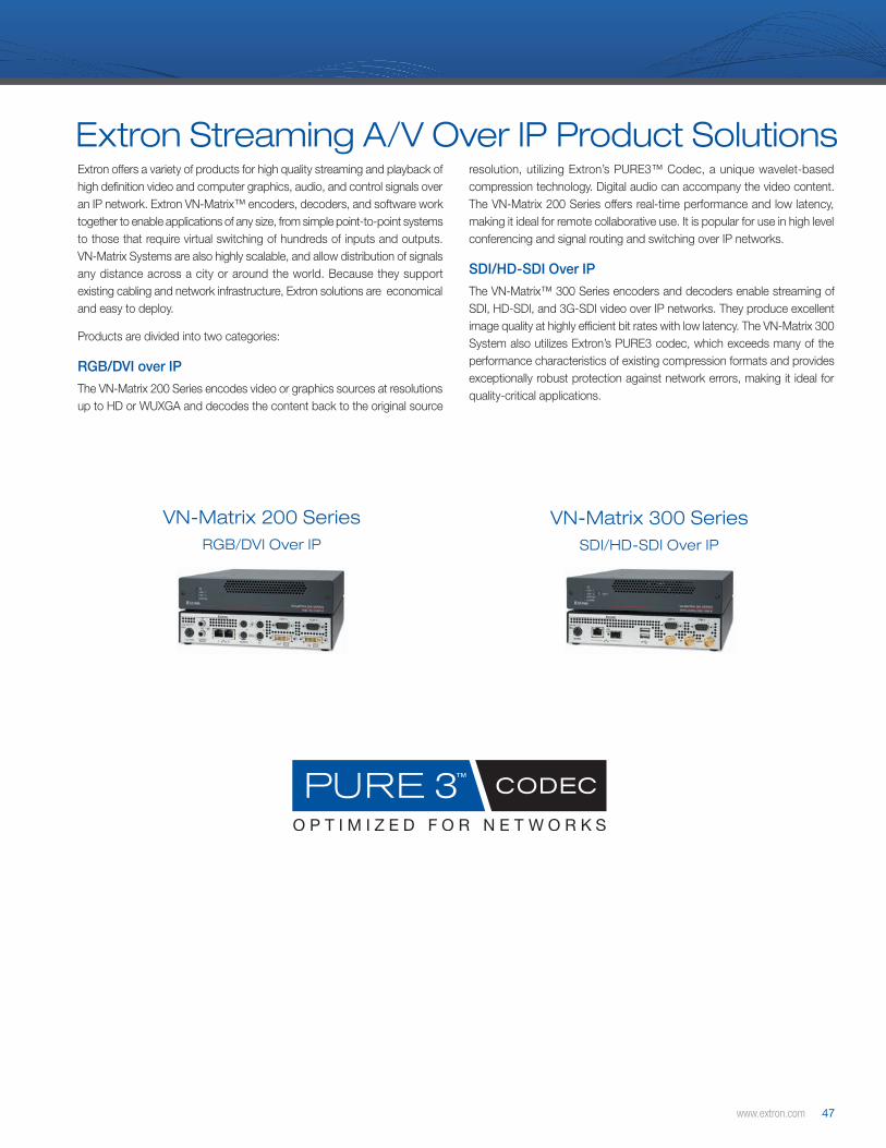
www.extron.com 47
Extron Streaming A/V Over IP Product SolutionsExtron offers a variety of products for high quality streaming and playback of high definition video and computer graphics, audio, and control signals over an IP network. Extron VN-Matrix™ encoders, decoders, and software work together to enable applications of any size, from simple point-to-point systems to those that require virtual switching of hundreds of inputs and outputs. VN-Matrix Systems are also highly scalable, and allow distribution of signals any distance across a city or around the world. Because they support existing cabling and network infrastructure, Extron solutions are economical and easy to deploy.
Products are divided into two categories:
RGB/DVI over IP
The VN-Matrix 200 Series encodes video or graphics sources at resolutions up to HD or WUXGA and decodes the content back to the original source
VN-Matrix 200 SeriesRGB/DVI Over IP
VN-Matrix 300 SeriesSDI/HD-SDI Over IP
resolution, utilizing Extron’s PURE3™ Codec, a unique wavelet-based compression technology. Digital audio can accompany the video content. The VN-Matrix 200 Series offers real-time performance and low latency, making it ideal for remote collaborative use. It is popular for use in high level conferencing and signal routing and switching over IP networks.
SDI/HD-SDI Over IP
The VN-Matrix™ 300 Series encoders and decoders enable streaming of SDI, HD-SDI, and 3G-SDI video over IP networks. They produce excellent image quality at highly efficient bit rates with low latency. The VN-Matrix 300 System also utilizes Extron’s PURE3 codec, which exceeds many of the performance characteristics of existing compression formats and provides exceptionally robust protection against network errors, making it ideal for quality-critical applications.

48 Extron Streaming A/V over IP Design Guide
VNE 200 DVIVN-Matrix Encoder for DVI-I and Digital Audio
VN-Matrix™ 200 SeriesDVI & RGB Video Over IP Encoders & Decoders
VNC 200 DVI-AVN-Matrix Codec for DVI-I, Digital Audio, Keyboard and Mouse
MODEL VERSION PART# VNC 200 DVI Codec for DVI-I, Keyboard & Mouse . . . . . . . . . . . . . . 60-1117-01
MODEL VERSION PART# VNC 200 DVI-A Codec for DVI-I, Audio/Keyboard/Mouse . . . . . . . . 60-1118-01
VNC 200 DVIVN-Matrix Codec for DVI-I, Keyboard and MouseUNIQUE FEATURES:
• Switchable encoder/decoder• Supports DVI-I video
RS-232, and keyboard & mouse command data
The VN-Matrix™ 200 Series provides real-time transmission of high resolution audio visual content across standard IP networks for live viewing, collaboration, storage, and playback. The VN-Matrix 200 Series encodes video or graphics sources at resolutions up to HD or WUXGA, streams the video over an IP network, then decodes the content back to the original source resolution. VN-Matrix applies Extron’s PURE3™ Codec, a unique wavelet-based compression technology. The VN-Matrix 200 Series offers real-time performance and low latency, making it ideal for remote collaborative and interactive or control applications. It can be deployed in live event streaming and high level conferencing for specialized projects.
FEATURES:• Supports up to WUXGA resolution (1920x1200)• HD Video over IP up to 1920x1080p• Low delay streaming - 35ms encode and 35ms
decode• Economical and easy to deploy• Supports refresh rates from 24 to 85 Hz• Dual 1 Gigabit network interfaces• Compatible with the VN-Matrix™ Recorder for
real-time record, store, and playback• S/PDIF digital audio interface• Extensive bit rate management
UNIQUE FEATURES:
• Switchable encoder/decoder• Supports DVI-I video, S/PDIF digital audio,
RS-232, and keyboard & mouse command data
RGB/DVI Over IP
MODEL VERSION PART#VNE 200 DVI Encoder for DVI-I & Digital Audio . . . . . . . . . . . . . . . . . . 60-1119-01
UNIQUE FEATURES:
• Encoder-only model• Supports DVI-I video and S/PDIF digital audio• Requires VNM Enterprise Controller

www.extron.com 49
MODEL VERSION PART# VNM Dual RMK VN-Matrix Dual Rack Mount Kit - Shelf . . . . . . . . . . . 60-1130-01VNM Quad RMK VN-Matrix Quad Rack Mount Kit - Shelf . . . . . . . . . 60-1131-01VNM MBU VN-Matrix Under Desk Mounting . . . . . . . . . . . . . . . . . . 60-1132-01VNM 12 PS 12 Unit Power Supply . . . . . . . . . . . . . . . . . . . . . . . . . . . . . . . . 70-763-01VNM PS VN-Matrix Replacement Power Supply . . . . . . . . . . . 70-761-01
RGB/DVI Over IP
VND 200 DVIVN-Matrix Decoder for DVI-I and Digital Audio
MODEL VERSION PART# VND 200 DVI Decoder for DVI-I & Digital Audio . . . . . . . . . . . . . . . . . . 60-1120-01
MODEL VERSION PART# VNM Software Decoder VN-Matrix 200 Series Software Viewer . . . . . . . . . . . 29-098-01
UNIQUE FEATURES:
• Decoder-only model• Supports DVI-I video and S/PDIF digital audio• Requires VNM Enterprise Controller
VN-Matrix 200 Series Accessories
VNM Primary Enterprise ControllerVN-Matrix Enterprise Controller
MODEL VERSION PART# VNM Enterprise Controller Enterprise Controller-Primary . . . . . . . . . . . . . . . . . . . . . 60-1133-01VNM Enterprise Controller Secondary Enterprise Controller-Secondary . . . . . . . . . . . . . . . . . 60-1134-01
UNIQUE FEATURES:
• Monitor, configure, and manage all VN-Matrix and VN-Matrix Recorder units as a system
• High Level Interface provides single point of control for external control systems
• Manage multiple VN-Matrix systems in a single or independent domain
• Secondary Controller serves as redundant control unit in mission-critical applications
VN-Matrix Software DecoderWindows™ Media Player Viewer
The PURE3 Software Decoder is a plug-in for Windows Media Player that enables a user to view PURE3 streams derived from progressive video inputs to VN-Matrix 200 Encoders. Both live and recorded streams can be viewed and controlled using standard Windows Media Player. This Software Decoder provides a cost-effective alternative to hardware decoding for users who may only need to access a VN-Matrix 200 stream on a casual or intermittent basis.
FEATURES:
• Windows Media Player Plugin for quick and simple installation
• Flexible decoding locations• Cost-effective

50 Extron Streaming A/V over IP Design Guide
SDI/HD-SDI Over IP
VN-Matrix™ 300 SeriesSDI, HD-SDI, & 3G-SDI over IP Encoders & Decoders
VNC 300 SDIVN-Matrix Codec for SDI
VNC 300 3G-SDIVN-Matrix Codec for 3G-SDI
VNC 300 for HD-SDIVN-Matrix Codec for HD-SDI
MODEL VERSION PART# VNC 300 SDI Codec for SDI . . . . . . . . . . . . . . . . . . . . . . . . . . . . . . . . . . . . . . . . . . 60-1122-01
MODEL VERSION PART# VNC 300 3G-SDI Codec for 3G-SDI . . . . . . . . . . . . . . . . . . . . . . . . . . . . . . . . . . . . . 60-1124-01
MODEL VERSION PART# VNC 300 HD-SDI Codec for HD-SDI . . . . . . . . . . . . . . . . . . . . . . . . . . . . . . . . . . . . . 60-1123-01
The VN-Matrix™ 300 Series encoders and decoders enable streaming of SDI, HD-SDI, and 3G-SDI video over IP networks. They produce excellent image quality at highly efficient bit rates with low latency. The VN-Matrix 300 System utilizes Extron’s PURE3 codec that exceeds many of the performance characteristics of existing compression formats and provides exceptionally robust protection against network errors, making it ideal for quality-critical applications.
FEATURES:• Streams serial digital video with embedded
audio• Video bit rates from 6 Mbps to 150 Mbps• 10 Bit YCrCb 4:2:2 encoding• Supports resolutions up to 6 Mbps to 150 Mbps• Low delay streaming - 35ms encode and 35ms
decode• Switchable between encode and decode
operation• Decoders are genlockable and frame-lockable
to external SDI reference
UNIQUE FEATURES:
• Switchable encoder and decoder in one unit• Supports HD-SDI or SDI video and embedded
audio
UNIQUE FEATURES:
• Switchable encoder and decoder in one unit• Supports 3G SDI, HD-SDI or SDI video and
embedded audio
UNIQUE FEATURES:
• Switchable encoder and decoder in one unit• Supports HD-SDI or SDI video and embedded
audio

www.extron.com 51
VND 300 SDIVN-Matrix Decoder for SDI
VND 300 3G-SDIVN-Matrix Decoder for 3G SDI
VND 300 HD-SDIVN-Matrix Decoder for HD-SDI
MODEL VERSION PART# VND 300 SDI Decoder for SDI . . . . . . . . . . . . . . . . . . . . . . . . . . . . . . . . . . . . . . . . 60-1125-01
MODEL VERSION PART# VND 300 HD-SDI Decoder for HD-SDI . . . . . . . . . . . . . . . . . . . . . . . . . . . . . . . . . . 60-1126-01
UNIQUE FEATURES:
• Decoder-only model• Supports SDI video and embedded audio
UNIQUE FEATURES:
• Decoder-only model• Supports 3G-SDI, HD-SDI, SDI video
and embedded audio
UNIQUE FEATURES:
• Decoder-only model• Supports HD-SDI, SDI video and embedded
audio
SDI/HD-SDI Over IP
VN-Matrix 300 Series AccessoriesMODEL VERSION PART# VNM Dual RMK VN-Matrix Dual Rack Mount Kit - Shelf . . . . . . . . . . . 60-1130-01VNM Quad RMK VN-Matrix Quad Rack Mount Kit - Shelf . . . . . . . . . 60-1131-01VNM MBU VN-Matrix Under Desk Mounting . . . . . . . . . . . . . . . . . . 60-1132-01VNM 12 PS 12 Unit Power Supply . . . . . . . . . . . . . . . . . . . . . . . . . . . . . . . . 70-763-01VNM PSR 12 Unit Power Supply with Redundancy . . . . . . . . . 70-762-01VNM PS VN-Matrix Replacement Power Supply . . . . . . . . . . . 70-761-01
MODEL VERSION PART# VND 300 3G-SDI Decoder for 3G-SDI . . . . . . . . . . . . . . . . . . . . . . . . . . . . . . . . . . . 60-1127-01
VNM RecorderVN-Matrix Recorder
MODEL VERSION PART# VN-Matrix Recorder Recorder . . . . . . . . . . . . . . . . . . . . . . . . . . . . . . . . . . . . . . . . . . . . . . . . 60-1121-01
UNIQUE FEATURES:
• Records visually lossless high-resolution encoded VN-Matrix™ streams over IP
• Virtual switching over IP• Record and synchronize up to 5 channels
per unit• Digitally record and playback video, audio,
& data
• 3TByte RAID 5 unformatted storage• 2TByte content storage

52 Extron Streaming A/V over IP Design Guide
Notes
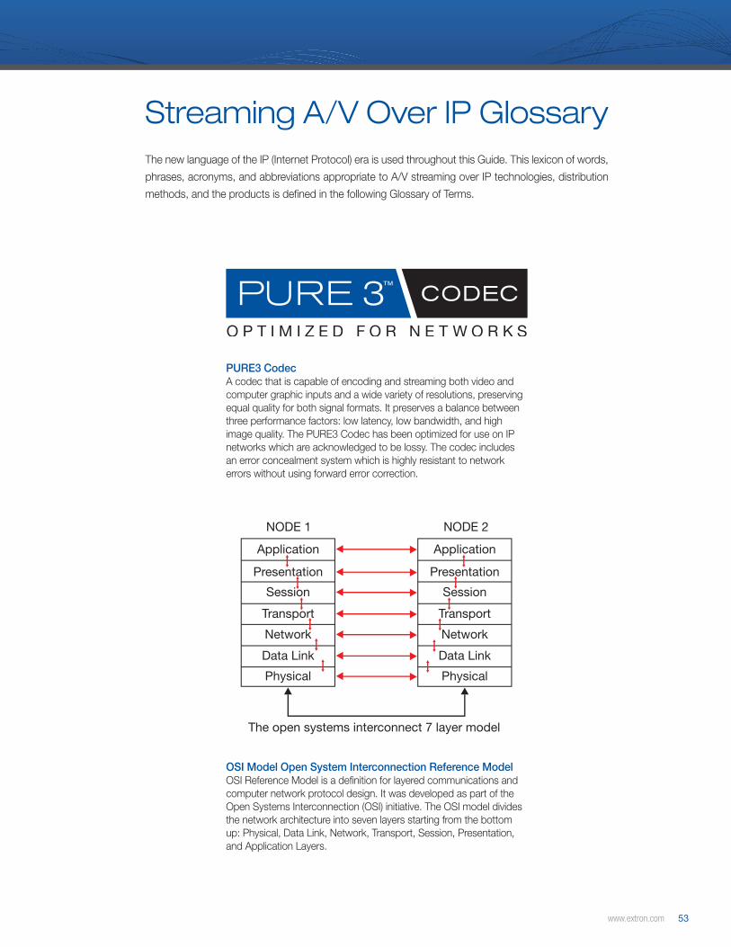
www.extron.com 53
Application
NODE 1
The open systems interconnect 7 layer model
NODE 2
Presentation
Session
Transport
Network
Data Link
Physical
Application
Presentation
Session
Transport
Network
Data Link
Physical
Applicationse.g. SMPT FTP HTTP
TransportTCP UDP
Internetwork
Network Interfaceand hardwaree.g. Ethernet; FDDI; Wireless
IP
ICMP
ARP RARP
OSI Model Open System Interconnection Reference ModelOSI Reference Model is a definition for layered communications and computer network protocol design. It was developed as part of the Open Systems Interconnection (OSI) initiative. The OSI model divides the network architecture into seven layers starting from the bottom up: Physical, Data Link, Network, Transport, Session, Presentation, and Application Layers.
PURE3 CodecA codec that is capable of encoding and streaming both video and computer graphic inputs and a wide variety of resolutions, preserving equal quality for both signal formats. It preserves a balance between three performance factors: low latency, low bandwidth, and high image quality. The PURE3 Codec has been optimized for use on IP networks which are acknowledged to be lossy. The codec includes an error concealment system which is highly resistant to network errors without using forward error correction.
Streaming A/V Over IP GlossaryThe new language of the IP (Internet Protocol) era is used throughout this Guide. This lexicon of words,
phrases, acronyms, and abbreviations appropriate to A/V streaming over IP technologies, distribution
methods, and the products is defined in the following Glossary of Terms.

54 Extron Streaming A/V over IP Design Guide
3G SDIThe new signal standard for serial digital, high definition video with 1920x1080 resolution and a 50Hz or 60Hz progressive frame rate. Up to 32 audio channels can be carried in the ancillary data. The 3G stands for 3 gigabits per second, which is 2 times the bit rate of a 1.485 Gbit HDSDI signal.
4:1:1 color spaceChroma, or color information, is sampled at one-fourth the horizontal resolution of the luminance, or black and white information.
4:2:0 color spaceChroma, or color information, is sampled at half the vertical and half the horizontal resolution of the luminance or black and white information.
4:2:2 color spaceColor information is sampled at half the horizontal resolution of the luminance, black and white information. 4:2:2 color sampling is popular in high-quality broadcast video systems.
4:4:4 color spaceColor information is sampled at the same rate as the luminance, black and white information. Video systems designed for capturing real images typically quantize color information at one-fourth to one-half the detail of luminance information. This is acceptable for real images, where sharp, on-off transitions between colors do not occur. Computer graphic pictures contain sharp, pixel transitions and require maintenance of 4:4:4 color space; otherwise, information is lost.
10BaseTAn Ethernet standard for transmitting data packets at 10 Mbps over twisted wire pair wire. 10Base-T is a shared media. When used with a hub, all network nodes must share the same 10 Mbps capacity. When used with a switch, each connection supports a 10 Mbps duplex capacity.
100BaseTAn Ethernet standard for transmitting at 100 Mbps over twisted pair wire. 100BaseT was also called “Fast Ethernet” when first deployed in 1995. Officially the IEEE 802.3u standard, it is a 100 Mbps version of 10Base-T. Like 10Base-T, 100Base-T is a shared media LAN when used with a hub and 100 Mbps duplex when used with a switch.
1000BaseT / Gigabit EthernetAn Ethernet standard that transmits at 1 Gbps over twisted pair wire. Use of Gigabit Ethernet is becoming commonplace and will eventually be used as frequently as 100BaseT connections.
A
ADSLAsymmetrical Digital Subscriber Line. One of a number of DSL technologies, and the most common one. ADSL is designed to deliver more bandwidth downstream (from the central office to the customer site) than upstream.
AnalogA continuous range of values to represent information. An infinite resolution of values can be established in an analog system.
Streaming A/V Over IP Glossary
AnimationsAnimations consist of motion image sequences produced synthetically on video processing or computing systems.
ArtifactsAny error in the perception or representation of any visual or aural information introduced by the involved equipment. Image artifacts appear as deviations from the original in the delivered image in video streaming systems.
ATMAsynchronous Transfer Mode. A standardized digital data transmission technology that is a cell-based switching technique that uses asynchronous time division multiplexing. This is the core protocol used over the SONET/SDH backbone of the ISDN (Integrated Services Digital Network).
B
B-FrameBi-directionally predictive coded picture. Contains predictive, difference information from the preceding and following I- or P-frame within a GOP. Data preceeding or following the B-frame are required to recreate video information in a B-frame.
BandwidthThe capacity or available bandwidth in bit/s, which typically means the net bit rate, channel capacity, or the maximum throughput of a logical or physical communication path in a digital communication system.
BERBit Error Rate. The rate at which bit errors are experienced across a data connection.
Best EffortDescribes a network service in which the network does not provide any guarantees that data is delivered or that a user is given a guaranteed quality of service level or a certain priority.
BidirectionalThe ability to move, transfer, or transmit in both directions.
Bit DepthThe number of bits used to represent the luminance and chrominance of a single pixel in a bitmapped image or video frame buffer. This concept is also known as bits per pixel (bpp), particularly when specified along with the number of bits used. Higher color depth gives a broader range of distinct colors.
Bit ErrorBit error indicates the number of bits of a data stream over a communication channel that have been altered. A bit error can result in unusable data or the corruption of an image in video streaming solutions
Bit RateThe number of bits that are conveyed or processed per unit of time. The bit rate is quantified using the bits per second (bit/s or bps) unit, often in conjunction with an SI prefix such as kilo- (kbit/s or kbps), mega- (Mbit/s or Mbps), or giga- (Gbit/s or Gbps).
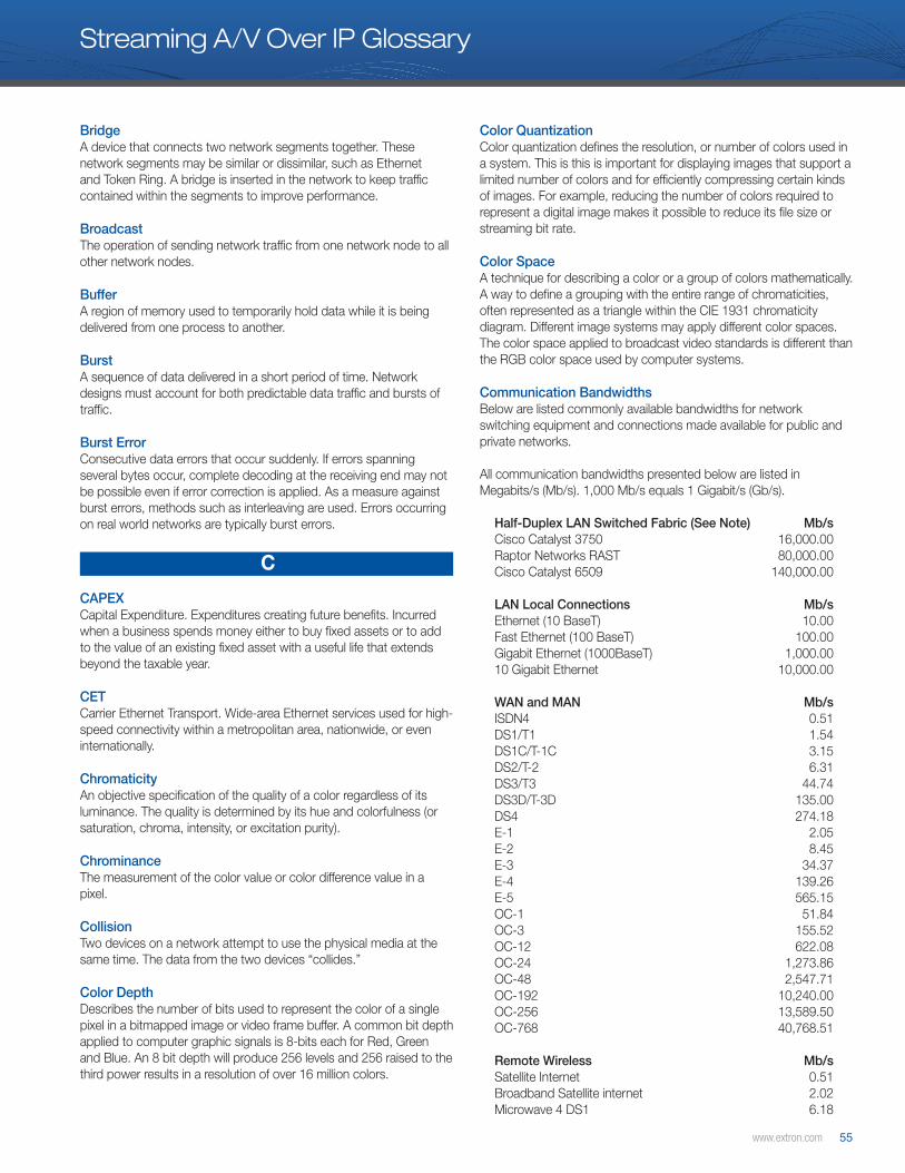
www.extron.com 55
Streaming A/V Over IP Glossary
BridgeA device that connects two network segments together. These network segments may be similar or dissimilar, such as Ethernet and Token Ring. A bridge is inserted in the network to keep traffic contained within the segments to improve performance.
BroadcastThe operation of sending network traffic from one network node to all other network nodes.
BufferA region of memory used to temporarily hold data while it is being delivered from one process to another.
BurstA sequence of data delivered in a short period of time. Network designs must account for both predictable data traffic and bursts of traffic.
Burst ErrorConsecutive data errors that occur suddenly. If errors spanning several bytes occur, complete decoding at the receiving end may not be possible even if error correction is applied. As a measure against burst errors, methods such as interleaving are used. Errors occurring on real world networks are typically burst errors.
C
CAPEX Capital Expenditure. Expenditures creating future benefits. Incurred when a business spends money either to buy fixed assets or to add to the value of an existing fixed asset with a useful life that extends beyond the taxable year.
CETCarrier Ethernet Transport. Wide-area Ethernet services used for high-speed connectivity within a metropolitan area, nationwide, or even internationally.
ChromaticityAn objective specification of the quality of a color regardless of its luminance. The quality is determined by its hue and colorfulness (or saturation, chroma, intensity, or excitation purity).
ChrominanceThe measurement of the color value or color difference value in a pixel.
CollisionTwo devices on a network attempt to use the physical media at the same time. The data from the two devices “collides.”
Color DepthDescribes the number of bits used to represent the color of a single pixel in a bitmapped image or video frame buffer. A common bit depth applied to computer graphic signals is 8-bits each for Red, Green and Blue. An 8 bit depth will produce 256 levels and 256 raised to the third power results in a resolution of over 16 million colors.
Color QuantizationColor quantization defines the resolution, or number of colors used in a system. This is this is important for displaying images that support a limited number of colors and for efficiently compressing certain kinds of images. For example, reducing the number of colors required to represent a digital image makes it possible to reduce its file size or streaming bit rate.
Color SpaceA technique for describing a color or a group of colors mathematically. A way to define a grouping with the entire range of chromaticities, often represented as a triangle within the CIE 1931 chromaticity diagram. Different image systems may apply different color spaces. The color space applied to broadcast video standards is different than the RGB color space used by computer systems.
Communication BandwidthsBelow are listed commonly available bandwidths for network switching equipment and connections made available for public and private networks.
All communication bandwidths presented below are listed in Megabits/s (Mb/s). 1,000 Mb/s equals 1 Gigabit/s (Gb/s).
Half-Duplex LAN Switched Fabric (See Note) Mb/s Cisco Catalyst 3750 16,000.00Raptor Networks RAST 80,000.00Cisco Catalyst 6509 140,000.00
LAN Local Connections Mb/sEthernet (10 BaseT) 10.00 Fast Ethernet (100 BaseT) 100.00 Gigabit Ethernet (1000BaseT) 1,000.00 10 Gigabit Ethernet 10,000.00
WAN and MAN Mb/sISDN4 0.51DS1/T1 1.54 DS1C/T-1C 3.15 DS2/T-2 6.31 DS3/T3 44.74 DS3D/T-3D 135.00 DS4 274.18 E-1 2.05 E-2 8.45 E-3 34.37 E-4 139.26 E-5 565.15 OC-1 51.84 OC-3 155.52 OC-12 622.08 OC-24 1,273.86 OC-48 2,547.71 OC-192 10,240.00 OC-256 13,589.50 OC-768 40,768.51
Remote Wireless Mb/sSatellite Internet 0.51Broadband Satellite internet 2.02Microwave 4 DS1 6.18

56 Extron Streaming A/V over IP Design Guide
Streaming A/V Over IP Glossary
802.11b 11.00IPDirect-Sat 20.00 802.11g 54.00Microwave OC3 155.3110G Laser 10,000.00
Please Note: Full-duplex switched fabric capacity is typically specified by manufacturers. Half-duplex capacity is typically more relevant to multicast video applications as it identifies the one-way sustained throughput directionally. Switched network architecture and intelligent switching features, including hardware or software routing, multicast routing protocol support, latency and other factors can be far more critical to consider than switched fabric capacity when designing switched networks.
CompressionThe art and science of reducing the amount of data required to represent a picture or a stream of pictures and sound before sending or storing it. Compression systems are designed to eliminate redundant or repeated information to the desired data level while allowing the original information to be reproduced to the desired quality.
CongestionOccurs when a link or node is carrying so much data that its quality of service deteriorates. Typical effects include queueing delay, packet loss or the blocking of new connections. A consequence of this is that increases in offered load lead to only small increases in network throughput, or to an actual reduction in network throughput.
Constant Bit Rate (CBR)Constant bit rate encoding means that the rate at which a codec’s output data should be consumed is constant. CBR is useful for streaming multimedia content on data communication channels which operate more efficiently or require the bit rate to remain within a tight tolerance. Typically the constant bit rate is created by stuffing bits into a variable bitrate signal which has a defined peak or maximum limit.
Constant QualityThe quality output from a process, such as video encoding remains constant, while the output, such as a bit rate may vary. Constant quality encoding will result in a variable bit rate if the nature of the video material changes.
ContentionThe media that network devices use to deliver data is overused and “contention” for the media is experienced.
COP-3A Code of Practices established by the MPEG Forum for the transmission of MPEG-2 transport streams which applies a technique known as Forward Error Correction to protect the enclosed data.
COP-4A Code of Practices for the transmission of uncompressed standard video at up to 270 Mbps and High Definition video at up to 1.485 Gbps which applies a technique known as Forward Error Correction to protect the enclosed data.
CoSClass of Service: Method of classifying traffic on a packet-by-packet basis using information in the type-of-service (ToS) byte to provide different service levels to different traffic. See also QoS.
CRC Cyclic redundancy check, CRC or polynomial code checksum is a method used to detect changes or errors in raw data, and is commonly used in digital networks, data communications and storage devices.
CSMA/CDCarrier Sense Multiple Access/Collision Detection. The Media Access Control method applied in Ethernet networks. When a device wants to gain access to the network, it checks to see if the network is quiet (senses the carrier). If it is not, it waits a random amount of time before retrying. If the network is quiet and two devices access the line at exactly the same time, their signals collide. When the collision is detected, they both back off and each waits a random amount of time before retrying.
D
Data Compression RatioThe ratio representing the data output from a compression system relative to the original data. A computer-science term used to quantify the reduction in data-representation size produced by a data compression algorithm.
Data ServicesA telecommunications service that transmits high-speed data rather than voice. Internet access is the most common data service, which may be provided by the telephone and cable companies as well as cellular carriers.
DecoderA device that does the reverse of an encoder, undoing the encoding so that the original information can be retrieved. The same method used to encode is usually just reversed in order to decode. Video over IP decoders accept IP data streams and output an analog or digital video signal.
DigitalA data technology that uses discrete (discontinuous) values.
Discrete Cosine Transform (DCT)A Fourier-related transform that is used to convert an image from a spatial domain to a frequency domain. Video systems then process the information in the frequency domain. Typically, more signal energy is located in the lower frequencies than the higher frequencies. The DCT is used in many video compression codecs including JPEG, MPEG, MPEG-2, MPEG-4 and H.264.
Discrete Wavelet Transform (DWT)A transform used to convert an image from a spatial domain to a wavelet domain. Two filters are involved. The first a “wavelet filter” is a high pass filter, and the second a “scaling filter” is a low pass filter. The DWT provides more efficient image compression than the DCT due to advantages from analyzing signals with sharp discontinuities or spikes.
www.extron.com 57
Streaming A/V Over IP Glossary
DSL Digital Subscriber Line. A generic name for a family of digital lines (also called xDSL) provided by telephone carriers to business and consumers.
Dual-link HDSDIA method applying two HDSDI signals 1920x1080 video at 50 or 60Hz as progressive frames at 12 bit depth or with 4:4:4 color quantization.
DVIDigital Visual Interface. The digital video connectivity standard that was developed by the DDWG – Digital Display Working Group. This connection standard offers two different connectors: one with 24 pins that handles digital video signals only and one with 29 pins that handles both digital and analog video. This standard uses TMDS – Transition Minimized Differential Signal from Silicon Image and DDC – Display Data Channel from VESA – Video Electronics Standards Association.
DVI-DDVI connector that supports digital signals only.
DVI-IConnector that supports both digital and analog signals.
E
EncoderA device, circuit, or algorithm that converts information from one format to another. Video over IP encoders take analog or digital video input signals and convert them to IP data streams which are transmitted over IP networks.
Error ConcealmentA method of concealing and hiding the impact of data lost during transmission. In video streaming systems, error concealment prevents lost network packets from disrupting a video frame or sequence of video frames.
Error CorrectionA method of detecting errors and reconstructing the original information using extra, redundant information sent along with the original data.
Error propagationA single error experienced produces a knock on effect to sequential information. In video streaming solutions, decoding products should provide a method by which a single error encountered affects only a small area of a picture and should not affect an entire frame or sequential frames of video.
EthernetA Local Area Network (LAN) standard officially known as IEEE 802.3. Ethernet and other LAN technologies are used for interconnecting computers, printers, workstations, terminals, servers, etc. within the same building or campus. Ethernet operates over twisted pair and over coaxial cable at speeds starting at 10 Mbps. For LAN interconnectivity, Ethernet is a physical link and data link protocol reflecting the two lowest layers of the OSI Reference Model.
Ethernet MAC FramesA digital data transmission unit or data packet that includes frame synchronization information and a data payload. The synchronization data makes it possible for the receiver to detect the beginning and end of the packet in the stream of symbols or bits.
F
FirewallA device that manages access of devices outside a network into a network, typically into a building or an enterprise. A firewall prevents unauthorized access to a network. It is also used to check on data delivered to and from a network to ensure the information is non-damaging.
Forward Error Correction (FEC)A system of error control for data transmission, whereby the sender adds redundant data to its messages, also known as an error-correction code. This allows the receiver to detect and correct errors (within some bound) without the need to ask the sender for additional data. The amount of FEC required to guarantee delivery is not certain. Each application must consider the predictability of the network and the amount of protection that is desired.
Frame LockMultiple video sources delivered together, that maintain frame synchronization are frame locked. Frame lock is required for delivery of stereoscope 3D imagery consisting of two locked signals or 4K resolution images, which are built up using four, synchronized HD video signals.
Frame RateThe frequency at which an imaging device produces unique, consecutive images called frames. The term applies equally to computer graphics, video cameras, film cameras, and motion capture systems. Frame rate is most often expressed in frames per second (FPS) and sometimes in progressive scan monitors as hertz (Hz). It can also be seen as refresh rate or vertical scan rate.
Frame RelayPublic, connection-oriented packet service based on the core aspects of the Integrated Services Digital Network. It eliminates all processing at the network layer and greatly restricts data-link layer processing. It allows private networks to reduce costs by using shared facilities between the end-point switches of a network managed by a Frame Relay service provider. Individual data-link connection identifiers (DLCIs) are assigned to ensure that each customer receives only its own traffic.
G
GatewayA network node equipped for interfacing with another network that uses different protocols. Also can be described as an entrance and exit into a communications network.
58 Extron Streaming A/V over IP Design Guide
Streaming A/V Over IP Glossary
GenlockA common technique where the video output of one source, or a specific reference signal, is used to synchronize other television picture sources together. Video sources that are genlocked have vertical sync pulses, which are synchronised together.
GOPA Group of successive pictures within a coded video stream. MPEG, MPEG-2, and MPEG-4 compression products apply a GOP structure to their video compression systems. Each coded video stream consists of successive GOPs. The visible frames are generated from the pictures contained in it,. A GOP begins with an I-frame containing the full temporal resolution of the video frame. A series of predictive information is calculated between I-frames. P-frames are predictive and estimate forward. B-frames apply bidirectional prediction and estimate forwards and backwards. Products will apply GOP structures in different manners to support the needs of different applications, whether: low delay, low bit rate or error resilience.
H
H.264 (MPEG-4 AVC)A Block-oriented, motion-compensation-based codec standard developed by the ITU-T Video Coding Experts Group (VCEG) together with the ISO/IEC Moving Picture Experts Group (MPEG). It is the product of a partnership effort known as the Joint Video Team (JVT). H.264 is used in such applications as Blu-ray Disc, videos from YouTube and the iTunes Store, DVB broadcast, direct-broadcast satellite television service, cable television services, and real-time videoconferencing.
HDSDIThe high-definition version of SDI specified in SMPTE-292M. This signal standard transmits audio and video with 10 bit depth and 4:2:2 color quantization over a single coaxial cable with a data rate of 1.485 Gbit/second. Multiple video resolutions exist, including progressive 1280x720 and interlaced 1920x1080 resolution. Up to 32 audio signals are carried in the ancillary data.
High-Definition VideoRefers to any video system of higher resolution than standard-definition (SD) video, and most commonly involves display resolutions of 1280×720 pixels (720p) or 1920×1080 pixels (1080i/1080p).
HubA shared transmission media to which devices on a network are interfaced. Ethernet hubs have mostly given way to Ethernet switches.
HopIn a packet-switching network, a hop is the trip a data packet takes from one router or intermediate point to another in the network.
Hop CountOn the Internet (or a network that uses TCP/IP), the number of hops a packet has taken toward its destination.
Huffman CodingA method of entropy encoding used in lossless data compression where the most frequently occurring values use the shortest codes.
I
IGMPInternet Group Management Protocol. Host-to-router signaling protocol for IPv4 to report their multicast group memberships to neighboring routers and determine whether group members are present during IP multicasting. Similarly, multicast routers, such as E-Series routers, use IGMP to discover which of their hosts belong to multicast groups and to determine if group members are present.
IGMP SnoopingIGMP snooping, as implied by the name, is a feature that allows a switch to “listen in” for multicast join requests on a network and deliver to end-point network devices when requested. A switch which supports IGMP snooping will not flood all of its ports with multicast traffic. IGMP snooping is supported in Layer 3 switches and some Layer 2 switches.
Image NoiseThe random variation of brightness or color information in images produced by the sensor and circuitry of a scanner or digital camera.
InterlaceIn TV, each video frame is divided into two fields with one field composed of odd numbered horizontal scan lines and the other composed of even numbered horizontal scan lines. Each field is displayed on an alternating basis.
Inter-Frame CodingA compression technique that spans multiple frames of video and eliminates redundant information between frames.
Intra-Frame CodingA method of video compression that compresses information within a single frame.
Intra-predictionIntra-prediction is an advanced compression technique applied in H.264 which takes advantage of the spatial redundancy within a frame to reduce the amount of data required to encode an I-frame.
IP (Internet Protocol)Internet Protocol defines addressing methods and structures for datagram encapsulation, allowing delivery of packets from a source to a destination based purely on addressing.
IP AddressA numerical label using the Internet Protocol assigned to devices in a network. The IP address for the source and destination are included in an IP datagram.
IPv4Internet Protocol version 4. The current version of the Internet Protocol, which is the fundamental protocol on which the Internet is based. It is a connectionless protocol for use on packet-switched Link Layer networks (e.g., Ethernet). It operates on a best effort delivery model, in that it does not guarantee delivery, nor does it assure proper sequencing or avoid duplicate delivery.
www.extron.com 59
Streaming A/V Over IP Glossary
IPv6Internet Protocol version 6. This new Internet Protocol is designed to replace and enhance the present protocol, which is called TCP/IP, or officially IPv4. IPv6 has 128-bit addressing, auto configuration, and new security features and supports real-time communications and multicasting. The primary equipment to apply IPv6 to is routing equipment, not source equipment.
J
JPEG (Joint Photographic Experts Group)Commonly used method of lossy compression for photographic images using a discrete cosine transfer function. The degree of compression can be adjusted, allowing a selectable tradeoff between storage size and image quality. JPEG typically achieves 10:1 compression with little perceptible loss in image quality. Produces blocking artifacts.
JPEG2000A wavelet-based image compression standard and coding system. There is a modest increase in compression performance of JPEG 2000 compared to JPEG. The main advantage offered by JPEG 2000 is the significant flexibility of the codestream, which allows for representing the image at various resolutions.
Jumbo FrameEthernet frames with more than 1500 bytes of payload. Network switches typically process packets with a maximum transfer unit, MTU of 1500 bytes. Use of jumbo packets can increase transmission efficiency by reducing the network transmission overhead used for the Ethernet datagram wrapper, which includes items such as the source and destination address.
L
LANLocal Area Network. Supplies networking capability to a group of computers in close proximity to each other such as in an office building, a school, or a home. A LAN is useful for sharing resources including files, printers, games, or other applications. A LAN often connects to other LANs and to the Internet or other WAN.
LatencyA measure of time delay experienced in a system, the precise definition of which depends on the system and the time being measured. In video processing or encoding products, it is a measure of the amount of time used to process an input signal. In a packet-switched network, it is measured either one-way (the time from the source sending a packet to the destination receiving it), or round-trip (the one-way latency from source to destination plus the one-way latency from the destination back to the source).
Layer 2 SwitchLayer 2 switches support functions of the second layer of the ISO model, and provide hardware switching. They are capable of switching packets between devices connected to the switch. A table is built in the switch based on the physical MAC address of the connected devices. A Layer 2 switch does not examine IP packets.
Layer 3 SwitchLayer 3 functionality of the third layer of the ISO model. Layer 3 switches examine network packets and make switching and routing decisions based on information in the Ethernet packets. They are used in networked audio and video network delivery systems and large or complex internetworks, such as the Internet. Layer 3 switches support packet routing, VLANs, IGMP-snooping, and multicast data stream delivery.
Lip SyncA technical term for matching lip movements seen in a video picture with voice. Audio and video is synchronized when lip sync is maintained.
Lossy CompressionMethod that discards (loses) some of the data in order to achieve its goal. The results that decompressing the data yields content that is different from the original, though similar enough to be useful in some way.
LPACLossless Predictive Audio Compression. An improved lossless audio compression algorithm developed by Tilman Liebchen, Marcus Purat, and Peter Noll at Institute for Telecommunications, Technical University Berlin (TU Berlin), to compress PCM audio in a lossless manner, unlike conventional audio compression algorithms, which are lossy. It is no longer developed because an advanced version of it has become an official standard under the name of MPEG-4 Audio Lossless Coding.
LuminanceThe measurement of the black to white value for a pixel.
M
M-JPEGInformal name for a class of video formats where each video frame or interlaced field of a digital video sequence is separately compressed as a JPEG image. Originally developed for multimedia PC applications, where more advanced formats have displaced it, M-JPEG is now used by many portable devices with video-capture capability, such as digital cameras.
MACMedia Access Control. The Media Access Control data communication protocol sub-layer provides addressing and channel access control mechanisms that make it possible for several terminals or network nodes to communicate within a multi-point network, typically a local area network (LAN). Access to the media may be spread out over time, or as in Ethernet, a mechanism is developed which allows random access, but provides a method for re-attempting use of the media if a collision is experienced.
Mathematically Lossless CompressionAllows the exact original data to be reconstructed from the compressed data. Data compacting in mathematically lossless processes is between 2:1 and 3:1. The term lossless is in contrast to lossy compression, which only allows an approximation of the original data to be reconstructed in exchange for better compression rates.

60 Extron Streaming A/V over IP Design Guide
Streaming A/V Over IP Glossary
Media PlayerA software application used for the playback of audio and video files.
M-JPEGMotion JPEG or M-JPEG video compression applies the discrete cosine transform to each video frame independently. No temporal compression is applied in MJPEG and no frame interdependence exists as with MPEG compression. Each video frame is encoded as though it is an MPEG I-frame. Editing and random access are easily facilitated in product designs applying MJPEG.
MPEG (Motion Picture Experts Group)A consortium of suppliers, users, and designers responsible for developing the motion picture video standard for audio and video compression and transmission.
MPEG-2The second generation standard for video compression of audio and video applying the discrete cosine transform. The standard includes a combination of lossy video and audio compression methods which permit storage and transmission of movies using currently available storage media and transmission bandwidth. Commonly used for digital television transmission, DVD, and other similar equipment.
MPEG-4A patented collection of methods defining compression of audio and visual (A/V) digital data. Uses of MPEG-4 include compression of A/V data for Web (streaming media) and CD distribution, voice (telephone, videophone), and broadcast television applications. MPEG-4 absorbs many of the features of MPEG-1 and MPEG-2 and other related standards, adding new features such as (extended) VRML support for 3D rendering, object-oriented composite files (including audio, video and VRML objects), support for externally specified Digital Rights Management, and various types of interactivity.
MPLSMultiprotocol Label Switching. A mechanism in high-performance telecommunications networks which directs and carries data from one network node to the next. MPLS makes it easy to create “virtual links” between distant nodes. It can encapsulate packets of various network protocols.
MTU (Maximum Transfer Unit)Each network has a maximum transfer unit or MTU, the maximum size for an Ethernet frame payload. Typically the MTU for a network is 1500 bytes. Routers break up data segments into two or more segments if the MTU is smaller than the payload in an Ethernet frame.
Multi-Pass TransformMulti-pass transforms return to a data set to carry out a process. Multi-pass transforms are often capable of supporting greater compression ratios, but use a greater amount of time to process the data.
Multi-Purpose TransformA multi-purpose transform is capable of converting more than one type of input format. The PURE3 codec is a multi-purpose transform in respect to its ability to process both video and computer graphic inputs which are different with respect to resolutions, color space, and color information.
MulticastMulticast addressing is a network technology for the delivery of information to a group of destinations simultaneously using the most efficient strategy to deliver the messages over each link of the network only once, and creating copies only when the links to the multiple destinations split. A single stream is sent from the source to a group of recipients.
NAS Network Attached Storage. One or more storage devices associated with a single server which exist as a node on a LAN (Local Area Network).
N
NATNetwork Address Translation. Method of concealing a set of host addresses on a private network behind a pool of public addresses. It allows conservation of registered IP addresses within private networks and simplifies IP address management tasks through a form of transparent routing, and increases network privacy by hiding internal IP addresses from external networks.
Native ResolutionThe native resolution of a LCD, LCoS, or other flat panel display refers to its single fixed resolution. It is the resolution at which an image was originally produced.
NTSCNational Television System Committee. The analog television system used in most of North America, South America, Japan, South Korea, Taiwan, Burma, and some Pacific Island nations and territories.
O
OPEX Operating Expense. An ongoing cost for running a product, business, or system.
Optical EthernetAn optical connection for delivering Ethernet packets. Ethernet signals have been traditionally interfaced on twisted pair cable. Optical Ethernet connections are used to preserve quality delivering the same signal over a greater distance, and for security concerns.
OSI Model Open System Interconnection Reference ModelOSI Reference Model is a definition for layered communications and computer network protocol design. It was developed as part of the Open Systems Interconnection (OSI) initiative. The OSI model divides the network architecture into seven layers, starting from the bottom up: Physical, Data Link, Network, Transport, Session, Presentation, and Application Layers.
Out of Order PacketIn computer networking, the delivery of data packets in a different order from which they were sent. Video decoders must account for out of order packets which may be experienced.

www.extron.com 61
Streaming A/V Over IP Glossary
OverbookingIn the telecommunications industry, overbooking -- such as in the frame relay world -- means that a telephone company has sold access to too many customers which basically floods the telephone company’s lines, resulting in an inability for some customers to use what they purchased.
OverheadAny data which is transferred on a communication link which is in addition to the content or data that is delivered. In IP networks, overhead includes: addressing, control, routing, redundant, error-checking, that error concealment data.
P
P-FramePredictive coded picture. Contains predictive information required to recreate a video frame.
PacketA block of data that is transmitted over a network in a packet-switched system. A packet is also referred to as a frame or datagram.
Packet JitterThe term jitter is used as a measure of the variability over time of the packet latency across a network. In real-time applications such as VoIP and video, variation in the rate at which packets in a stream are received that can cause quality degradation. Video decoders must account for jitter, which may be experienced delivering packets across a network.
Packet LossOccurs when one or more packets of data traveling across a computer network fail to reach their destination. Packet loss is distinguished as one of the three main error types encountered in digital communications; the other two are bit error and spurious packets caused by noise. Packet loss is typically experienced in the real world as a random burst of packet loss.
PALPhase Alternate Line. An analog television encoding system used in broadcast television systems primarily in Europe, Asia, Africa, and Australia .
PixelPicture Element. The smallest unit or area of a video screen image that can be turned on or off, or varied in intensity.
Plug-inA program of data that enhances, or adds to, the operation of a parent program. Software decoders often use a plug-in provided in media players.
Private Network A communication network owned by one or more firms for their exclusive use.
Pro-MPEG ForumAn association of broadcasters, program makers, equipment manufacturers, and component suppliers with interests in realizing the interoperability of professional television equipment, according to the implementation requirements of broadcasters and other end-users. The Forum has been in existence for approximately eight years and has over 130 members.
ProgressiveA method for displaying, storing or transmitting moving images in which all the lines of each frame are drawn in sequence.
Public NetworkA network established and operated by a telecommunications provider, for specific purpose of providing data transmission services for the public. The Internet is a public network.
PURE3 CodecA codec that is capable of encoding and streaming both video and computer graphic inputs and a wide variety of resolutions, preserving equal quality for both signal formats. It preserves a balance between three performance factors: low latency, low bandwidth and high image quality. The PURE3 Codec has been optimized for use on IP networks that are acknowledged to be lossy. The codec includes an error concealment system which is highly resistant to network errors without using forward error correction.
Q
QoSQuality of Service. Performance, such as transmission rates and error rates, of a communications channel or system. A suite of features that configure queuing and scheduling on the forwarding path of an E-Series router. QoS provides a level of predictability and control beyond the best-effort delivery that the router provides by default. (Best-effort service provides packet transmission with no assurance of reliability, delay, jitter, or throughput.) See also CoS.
QuantizationThe procedure of converting a signal from one set of defined values to a new discrete set of values. An analog to digital conversion quantizes a continuous or infinite set of values to a smaller set of discrete, digital values.
R
Random ErrorErrors in measurement that lead to measured values being inconsistent when repeated measures of a constant attribute or quantity are taken.
Real ImagesCollected from the real world through image sensors. Video collected from film or electronic cameras can be considered real images.
62 Extron Streaming A/V over IP Design Guide
Streaming A/V Over IP Glossary
Real-timeA system is said to be real-time if the operation delivers a correct value in the time and frequency in which it is required. The video system applied in North America, NTSC requires a real-time system capable of delivering 30 frames per second.
RedundancyRepeated data or equipment that provides a backup if the primary data or equipment fails.
Refresh RateAlso called “Vertical Scan Frequency” or “Vertical Scan Rate”. The number of times in a second that display hardware draws a new video frame.
RouterA network device that forwards packets from one network to another. Routing is a Layer 3 function. Routers forward packets based on programmed or “learned” routing tables. Each incoming network packet is examined and a decision is made where to forward it. The destination address in the packets determines the port where outgoing packets are needed. In large-scale enterprise routers, the current traffic load, congestion, line costs and other factors determine which line to forward to.
RTPReal-time Transport Protocol, an IETF standard for streaming real-time multimedia over IP in packets.
RTSPReal Time Streaming Protocol. A network control protocol designed for use in entertainment and communications systems to control streaming media servers.
Run Length EncodingSimple form of data compression in which runs of data are stored as a single data value and count, rather than as the original run. This is most useful on data that contains many such runs: for example, relatively simple graphic images such as icons, line drawings, and animations.
S
ScalabilityThe property of a system, a network, or a process, which indicates its ability to handle growing amounts of work in a graceful manner with a limit that is unlikely to be encountered.
ScalerA device for converting video signals from one size or resolution to another: usually “upscaling” or “upconverting” a video signal from a low resolution (e.g. standard definition) to one of higher resolution (e.g. high definition television).
ScalingA conversion of a video or computer graphic signal from a starting resolution to a new resolution. Scaling from one resolution to another is typically done to optimize the signal for input to an image processor, transmission path or to improve its quality when presented on a particular display.
SDHSynchronous Digital Hierarchy. See SONET.
SDISerial Digital Interface. Standard definition video is carried on this 270 Mbps data transfer rate. Video pixels are characterized with a 10-bit depth and 4:2:2 color quantization. Ancillary data is included on this interface and typically includes audio or other metadata. Up to sixteen audio channels can be transmitted. Audio is organized into blocks of four stereo pairs.
SDSLSymmetrical Digital Subscriber Line. Offers bandwidth of up to 2.3 Mbps upstream and downstream over a single twisted pair copper phone line, over distances up to about 10,000 feet on an unrepeatered basis.
SFPSmall Form-factor Pluggable. The SFP is an interface used in fiber optic connections for direct signal connections or packet switched networks.
Signal NoiseA random fluctuation in an electrical signal, a characteristic of all electronic circuits.
Single Pass TransformTransformation process that is carried out making only one examination of a data set. A single pass transform is required to maintain a low delay.
SLA Service Level Agreement. An agreement between a network service provider and the user defining an established set of metrics to measure the service delivered relative to the service delivered. A SLA typically identifies the bandwidth delivered, Quality of Service and service response time.
Software DecoderA software decoder provides a means to decode audio/video streams in software without requiring use of a dedicated hardware appliance. Software decoders are typically used on PCs using a browser page, media player or special purpose application.
SONETSynchronous Optical Networking. A standardized multiplexing protocol that transfers multiple digital bit streams over optical fiber using lasers or light-emitting diodes (LEDs).
Spatial ResolutionA measurement of the resolution in a single frame of video. The horizontal resolution multiplied by the vertical resolution.
Spanning TreeIEEE 802.1d. is a protocol that allows networks to prevent loops, or multiple paths from developing between a source and a destination. Network routers communicate with each other using spanning tree protocol to prevent traffic from reaching unnecessary destinations. Spanning tree and other routing protocols prevent multicast video traffic from flooding networks with unnecessary, disruptive traffic.

www.extron.com 63
Streaming A/V Over IP Glossary
Sub-frame CompressionCompression that is not carried out on an entire frame of video, but only a part of a video frame.
Subnet MaskNumber of bits of the network address used to separate the network information from the host information in a Class A, Class B, or Class C IP address, allowing the creation of subnetworks. In binary notation, a series of 1s followed by a series of contiguous 0s. The 1s represent the network number; the 0s represent the host number. Use of masks can divide networks into subnetworks by extending the network portion of the address into the host portion. Subnetting increases the number of subnetworks and reduces the number of hosts.
SVGASuper VGA. A screen resolution of 800x600 pixels and above.
SwitchA device that cross-connects network devices. Today, switches are broadly deployed on modern industrial and consumer networks. Switching is a Layer 2 function. Ethernet frames are delivered between MAC addresses connected to network switches.
Switched FabricA network topology where network nodes connect with each other via one or more network switches (particularly via crossbar switches, hence the name). The term is in contrast to a broadcast medium, such as early forms of Ethernet.
SXGASuper XGA. A standard screen resolution of 1280x1024 pixels.
SXGA+Super Extended Graphics Array Plus. Commonly used on 14 inch or 15 inch laptop LCD screens with a resolution of 1400 × 1050 pixels.
Symmetrical processingTwo processes are symmetric if the input process is of equal magnitude and complexity to the output process. The encoding and decoding processes in the PURE3 codec are symmetric.
SynchronizationTimekeeping that requires the coordination of events to operate a system in unison. Synchronization in video systems can refer to a number of items. Lip-sync is the synchronization of audio and video. Genlock refers to alignment of vertical sync in video signals. Frame-sync or framelock refers to the alignment of video frames in systems with multiple video sources.
Synthetic ImagesSynthetic images are produced in artificial processes, for example in video processing or computing systems.
T
TelepresenceA set of technologies that allows individuals to feel as if they were present, to give the appearance that they were present, or to have an effect, at a location other than their true location. Telepresence solutions include the delivery of audio, video, data and computer
graphic information over IP networks using video over IP encoders and decoders.
TCP (Transmission Control Protocol)A connection-oriented protocol designed to provide a reliable end-to-end data delivery over an unreliable internetwork.
TCP/IP ModelA set of communications protocols used for the Internet and other similar networks. It is named for two of the most important protocols in it: the Transmission Control Protocol (TCP) and the Internet Protocol (IP). The eight functions of the OSI model have been combined into only four layers in the TCP/IP model.
Temporal ResolutionA measurement of elements occurring in time. Example: the temporal resolution of video may be 50 or 60 frames per second.
Thin ClientA computer or a computer program that depends heavily on some other computer (its server) to fulfil its traditional computational roles.
TransformA method applied to convert a data set from one domain to another. The rationale for transforming the data into a new domain is typically to make handling and processing the information easier. One common example is the RGB to YUV color space transformation. Imagery collected from the real-world using sensors is done in an RGB color space. The RGB information is then transformed to a component YUV domain allowing independent processing of luminance and color information.
TransformationA change or alteration. In the context of still image compression, a picture frame is input as a fixed resolution of rows and columns of pixels and a transformed into a frequency domain applying the Discrete-Cosine Transform.
Transport StreamA defined package for delivering data. Transport Streams are multiplexes of audio, video and other content that are usually broadcast over-the-air, although they can be streamed over IP networks too.
TTLTime To Live. Multicast streaming traffic is typically programmed with a TTL value indicating the number of router hops that are permissible for the packet.
U
UDP (User Datagram Protocol)A connectionless protocol providing “best effort” delivery of packets across networks. UDP is frequently used in real-time streaming applications were best effort delivery is acceptable and the network devices and applications manage data flow control and errors.
64 Extron Streaming A/V over IP Design Guide
Streaming A/V Over IP Glossary
UnicastThe sending of messages to a single network destination host on a packet switching network. Sending a separate copy of the media stream from the server to each recipient.
V
Variable Bit Rate (VBR)Varies the amount of output data per time segment. VBR allows a higher bit rate or storage space to be allocated to more complex segments of video and a lower bit rate to be allocated to less complex segments.
Vertical FrequencySee “Refresh Rate”.
VGAVideo Graphics Array. A widely used analog interface between a computer and monitor that uses a 15-pin plug and socket. The original VGA resolution was 640x480 pixels.
VideoA format for transmitting and storing moving pictures. Video is transmitted and stored in various analog and digital physical formats.
Visually Lossless CompressionAllows the reproduced image to appear to human vision to be identical to the original image.
VLANVirtual LAN. A group of devices on a network with a common set of requirements that communicate as if they were attached to the same broadcast domain, regardless of their physical location. A VLAN is a Layer 3 network function. A group of network devices can be grouped together into a functionally separate logical network. VLAN and their network traffic will be segmented from other devices that may be connected to the same physical system.
VODVideo on Demand. Unicast streaming video offered by service providers that enables the reception of an isolated video session per user with rewind, pause, and similar VCR-like capabilities.
VPNVirtual Private Network. A method of providing a private network connection via a secure communications tunnel over the Internet. VPNs maintain privacy applying tunneling protocol, encryption, and security procedures.
W
WANWide Area Network. A computer network that covers a broad area such as a link across a metropolitan, regional, or national boundary.
X
XGAExtended Graphics Array. A screen resolution of 1024x768 pixels.
Y
YUVA component color system that organises the black and white luminance information separately from the color or chrominance information. YPrPb and YCBCr are also component color systems. YPbPr is the analog version of the YCBCR color space; the two are numerically equivalent.

Worldwide Sales Offices
Extron Electronics, Asia 135 Joo Seng Road #04-01PM Industrial BuildingSingapore 368363
Sales: +800.S3.EXTRON +800.7339.8766 (Inside Asia only) +65.6383.4400 Fax: +65.6383.4664
Extron Electronics, Japan Kyodo Building16 IchibanchoChiyoda-ku, Tokyo 102-0082Japan
Sales: +81.3.3511.7655 Fax: +81.3. 3511.7656
Extron Web Site www.extron.com
Extron Electronics, China 686 Ronghua Road, Songjiang DistrictShanghai 201611China
Sales: +400.883.1568 (Inside China Only) +86.21.3760.1568 Fax: +86.21.3760.1566
Extron Electronics, Middle East United Arab Emirates, DubaiDubai Airport Free ZoneF12, PO Box 293666
Sales: +971.4.2991800 Fax: +971.4.2991880
Extron Electronics, USA - WestHeadquarters
1230 South Lewis StreetAnaheim, California 92805USA
Sales/Tech Support: +800.633.9876 Order Support: +800.633.9873 (Inside USA & Canada only) +1.714.491.1500 Fax: +1.714.491.1517
Extron Electronics, Europe Hanzeboulevard 103825 PH AmersfoortThe Netherlands
Sales: +800.EXTRON.S3 +800.3987.6673 (Inside Europe only) +31.33.453.4040 Fax: +31.33.453.4050
Extron Electronics, USA - East 2205 Westinghouse Boulevard, Suite 102Raleigh, North Carolina 27604USA
Sales: +800.633.9876 (Inside USA & Canada only) +1.919.863.1794 Fax: +1.919.863.1797
S3 Sales & Technical Support Hotline
USA: +800.633.9876 (Inside USA only) +1.714.491.1500Europe: +800.EXTRON.S3 +800.3987.6673 (Inside Europe only) +31.33.453.4040
Asia: +65.6383.4400 Japan: +81.3.3511.7655 China: +400.883.1568 (Inside China Only) Dubai: +971.4.2991800
Normal Office Hours USA: 7:00 am – 5:30 pm (PST) Monday – FridayEurope: 0900 – 1800 (+1 GMT) Monday – FridayAsia: 0900 – 1800 (+8 GMT) Monday – Friday
Japan: 0900 – 1800 (+9 GMT) Monday – Friday China: 8:00 am – 5:00 pm (+8 GMT) Monday – Friday Dubai: 8:30 am – 5:30 pm (+4 GMT) Sunday – Thursday
Order & Support Fax Line USA: +1.714.491.1517 Europe: +31.33.453.4050Asia: +65.6383.4664
Japan: +81.3.3511.7656 China: +86.21.3760.1566 Dubai: +971.4.2991880
24-Hour Technical Support Dial +800.633.9876 (Inside USA & Canada only) then press (3) — 24-Hour Technical Support. Calls are returned within 30 minutes.
Special Orders & Handling Next day shipment for stock items ordered by 2:00 pm (PST) is standard.
Open Account Information Qualified accounts may receive Net 30 day payment terms upon approved credit and acceptance of Extron’s international credit policy. A hard copy Purchase Order (PO) is required by fax or mail.
International Shipping Terms Ex works Extron Anaheim, Ex works Extron Amersfoort, Ex works Extron Singapore, Ex works Extron Shanghai, and Ex works Extron Dubai
Powered Product Warranty Three years parts and laborTouchscreen display and overlay components carry a one year parts and labor warranty, while the electronic components are covered by the Extron three year warranty.
Cable Performance Warranty Limited lifetime. Extron Cable Products will be free from defects in material and workmanship for as long as you or your customer own the cable.
System Integrator® Speaker Warranty
Five years parts and labor
Please refer to Extron business policies for full details.

© 2010 Extron Electronics. All rights reserved. All trademarks mentioned are the property of their respective owners. 06-201068-1952-01
Rev. A English - NP