
StreamDiver Utilizing New Hydropower Potential - Voith | … · hydropower plants Over 85 percent...
6
1 StreamDiver ® Utilizing New Hydropower Potential
Transcript of StreamDiver Utilizing New Hydropower Potential - Voith | … · hydropower plants Over 85 percent...

1
StreamDiver®
Utilizing New Hydropower Potential

32
Challenges for low head hydropower plantsOver 85 percent of all existing dams in the world remain unused for hydropower generation. The StreamDiver turbine was developed to tap this potential, especially at low head sites which so far could not be exploited.
1+2 Typical Power Plant Arrangement with StreamDiver
1 2
Even though hydropower accounts for the largest share of renewable energies worldwide, there is still sufficient potential for energetic development. Until recently, run of river plants with low heads were regarded as uneconomical and therefore often remained unused. In order to take advantage of this unused potential, in cooperation with its subsidiary Kössler, which acts as Voith’s competence center for Small Hydro in Europe, Voith has developed the StreamDiver, a new compact propeller turbine particularly suited to taking over where conventional plants may not be viable. The set-up and eco-friendly features make the power unit especially feasible where weirs or dams already exist. The StreamDiver offers a compact, low-maintenance and oil-free alternative in the field of hydropower.
StreamDiver Features Your benefits
Oil free turbine solution+ environmental acceptance
Simplified technical complexity
+ low maintenance+ high availability+ no turbine peripheral equipment required
Standardized design
+ short delivery times+ approved concept+ minimized spare part administration
Compact and submersible turbine design
+ flexible plant integration+ easy handling for maintenance and service+ reduction of civil costs
1 2
Simplicity as key to reliability Higher availability and less technical complexity: the StreamDiver’s compact and modular design and its maintenance-free operation minimizes costs.
The StreamDiver will allow construction work to be kept at a minimum. The power unit is installed directly in the water with only the power cable exposed. The entire drivetrain, consisting of the turbine, shaft, bearings and generator, is situated in a bulb-turbine-type housing. In addition, the bulb is filled with water, which completely lubricates its bearings, ruling out any risk of water contamination. The turbine itself is designed as a propeller turbine, meaning that neither rotor blades nor guide vanes are movable. These features negate the need for a visible or accessible power house.By switching individual turbines on and off, or by regulating the turbine speed an operator can control the flow of his plant.
For shutdowns a separate gate is used, which simultaneously allows for speed to be controlled in order to start and synchronize the compact turbines. All these design solutions support a comparatively low total cost of ownership.Conventional hydropower plants are designed according to individual requirements. The StreamDiver, in contrast, is an affordable serial product. It has numerous application possi-bilities around the world. The technical features of the Stream-Diver represent the latest developments in the field of small hydropower.
1 Turbine housing with guide vanes
2 Radial and axial bearing coating on shaft ends
3 Shaft
4 Generator
5 Runner
6 Bulb nose
StreamDiver Main Components
1
2 3
4
5
2 2
6

54
• The discharge through turbine for single unit is limited in a range of 2 - 12 m3/s.
• The typical head range for StreamDiver is 2 – 6 m. However, in certain cases the standardized design modules can be engineered for high heads up to 10 m if the project is economically attractive.
• The civil structure shall facilitate the minimum submer-gence of the machine for cavitation free operation of the StreamDiver.
• Unit flow is limited by the runner diameter.
1
3
2
Application diagram:
The application diagram allows a preliminary module size selection based on rated head and flow. To find out the best array and number of compact turbines, conditions such as annual flow, head duration curve and overall physical limitations are also to be considered. For identifying the best project specific solution, the application range of the different modules is overlapping. The following operational criteria should be considered:
A B C1 D E
SD Module mm mm m2 mm mm
SD 7.9 1380 1580 2,2 790 6000
SD 8,95 1560 1790 2,7 900 6700
SD 10.15 1770 2030 3,5 1020 7600
SD 11.55 2020 2310 4,5 1160 8700
SD 13.10 2380 2620 5,7 1310 9900
Main dimensions:
1 Minimum intake gross area in case of penstock or channel applications.2 Dimension F will be defined by Voith. In general the draft tube exit needs to be placed below the minimum tail water level.
The StreamDiver is a non-regulated machine. In order to utilize the complete potential of any site, multiple number of units are required to be installed. Optionally, the StreamDiver can be equipped with a frequency converter to allow variable speed opera-tion. In this case the StreamDiver unit can follow the available flow.
Minimum Tail Water Level
StreamDiver sizing:
The main dimensions of the StreamDiver will vary depending on the selected module size. The setting of the turbine will be given by the minimum tail water level. The below given turbine layout is basis for the preliminary planning. Nevertheless, the final plant and intake layout needs to be adopted to the local requirements with the support of Voith.
Typical multi unit operation diagram:
1.50 2.50 3.50
Net head [m]
4.50 5.50 6.50
StreamDiver Modules SD 13.10 SD 11.55 SD 10.15 SD 8.95 SD 7.90
550 kW
450 kW
350 kW
250 kW
150 kW
12.0
10.0
8.0
6.0
4.0
2.0
0.0
[m3 /
s]
50 kW
500 100
Time [days/year]200 300 400
70
90
110
130
150
170
190
210
230
rate
d un
it flo
w [m
3/s
] Plant flow regulation with fixed speed StreamDiver
Plant flow regulation with variable speed StreamDiver
15°
BE
C
F2
B x
B
øA
øD
76
Nam liber tempor cum nobis.
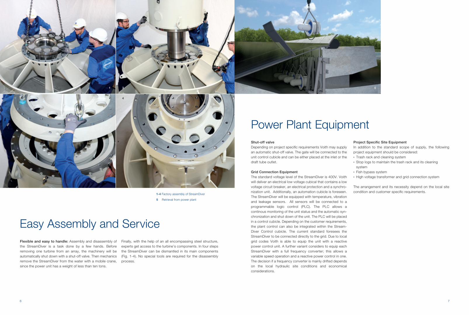
Easy Assembly and ServiceFlexible and easy to handle: Assembly and disassembly of the StreamDiver is a task done by a few hands. Before removing one turbine from an array, the machinery will be automatically shut down with a shut-off valve. Then mechanics remove the StreamDiver from the water with a mobile crane, since the power unit has a weight of less than ten tons.
Finally, with the help of an all encompassing steel structure, experts get access to the turbine’s components. In four steps the StreamDiver can be dismantled in its main components (Fig. 1-4). No special tools are required for the disassembly process.
Power Plant EquipmentShut-off valveDepending on project specific requirements Voith may supply an automatic shut-off valve. The gate will be connected to the unit control cubicle and can be either placed at the inlet or the draft tube outlet.
Grid Connection EquipmentThe standard voltage level of the StreamDiver is 400V. Voith will deliver an electrical low voltage cubical that contains a low voltage circuit breaker, an electrical protection and a synchro-nization unit. Additionally, an automation cubicle is foreseen. The StreamDiver will be equipped with temperature, vibration and leakage sensors. All sensors will be connected to a programmable logic control (PLC). The PLC allows a continous monitoring of the unit status and the automatic syn-chronization and shut down of the unit. The PLC will be placed in a control cubicle. Depending on the customer requirements, the plant control can also be integrated within the Stream-Diver Control cubicle. The current standard foresees the StreamDiver to be connected directly to the grid. Due to local grid codes Voith is able to equip the unit with a reactive power control unit. A further variant considers to equip each StreamDiver with a full frequency converter; this allows a variable speed operation and a reactive power control in one. The decision if a frequency converter is mainly drifted depends on the local hydraulic site conditions and economical considerations.
Project Specific Site EquipmentIn addition to the standard scope of supply, the following project equipment should be considered:• Trash rack and cleaning system• Stop logs to maintain the trash rack and its cleaning
system• Fish bypass system• High voltage transformer and grid connection system
The arrangement and its necessity depend on the local site condition and customer specific requirements.
1
2
3
4
5
1-4 Factory assembly of StreamDiver
5 Retrieval from power plant

98
Lorem ipsum dolor
Hydropower Plant layout examples
The principle idea is to place the StreamDiver under water. The electrical and plant peripheral equipment can be placed safely and is easily acces-sible outside the river stream.
Case Study 1: Integration in existing flood regulation weir
Case Study 2: Residual flow power plant
Case Study 3: Integration in existing Penstock
Control cabinet Existing gate way to access unit with mobile craneHead water level
Hydraulic power unit
Existing flood regulation gate
Existing structure New stream diver power plant
Draft tube gateStreamDiver Draft tube
Tail water level
New gates
Cable channel
Tail water levelDraft tube gate
Draft tube StreamDiverPenstock connection
Cable channel and disassembly slot
Control cabinet
Water level
Trash rack
Cable channel and disassembly slot
StreamDiver
Draft tube gate
Tail water level
Stop logs GateControl cabinet

t339
0e
Voith Hydro Holding GmbH & Co. KGAlexanderstraße 1189522 Heidenheim, GermanyTel. +49 7321 37 0Fax +49 7321 37 7828www.voith.com
A Voith and Siemens Company


