
Strategic Timing Low Impact Development (LID) Guidance Manual€¦ · Bioretention 5.2.6 Inspection...
126
LID LID Strategic Timing Lot Level Conservation Lot Level Treatment Low Impact Development (LID) Guidance Manual Funded by a NOAA grant through North Carolina Coastal Nonpoint Source Program Division of Water Quality North Carolina Division of Coastal Management North Carolina Coastal Federation Conservation Design Pollution Prevention
Transcript of Strategic Timing Low Impact Development (LID) Guidance Manual€¦ · Bioretention 5.2.6 Inspection...

LIDLID
Strategic Timing
Lot Level Conservation
Lot Level Treatment
Low Impact Development
(LID)
Guidance Manual
Funded by a NOAA grant through
North Carolina Coastal Nonpoint Source Program
Division of Water Quality
North Carolina Division of Coastal Management
North Carolina Coastal Federation
Conservation Design
Pollution Prevention


Brunswick County Low Impact Development (LID) Guidance Manual
i
Project Background
This guidance document is part of an ongoing effort to encourage and allow for Low Impact Development (LID) technologies as an alternative and voluntary option for developers to satisfy stormwater requirements and watershed goals. This project was funded by a grant secured by the North Carolina Coastal Federation (NCCF) from the National Oceanic and Atmospheric Administration (NOAA) and includes several public and private partners including Brunswick County, New Hanover County, City of Wilmington, North Carolina Coastal Nonpoint Source Program of the Division of Water Quality, and NCCF. Larry Coffman, a national LID consultant, provided the initial technical support for the project and prepared the first drafts of the LID guidance manual. NCCF worked jointly with the consultant to provide technical support for the project. The scope of the project included the following: 1. Review of current ordinances to determine roadblocks. 2. Comprehensive review of LID principles and practices to determine appropriateness for coastal application. 3. Guidance on LID technologies compliant with local and State requirements. 4. Preparation of an LID guidance manual and resolution to enable developers to use LID on a voluntary basis. 5. Distribution of educational and outreach materials. 6. Development of an LID spreadsheet modeling tool to aid engineers, planners, and developers with design and permitting of LID projects.
Acknowledgements
NCCF and County staff took the lead role in facilitating the County project team, organizing logistics for meetings, and workshops. Special acknowledgment should be given to Brigit Flora, Stormwater Engineer for Brunswick County, for all of her technical support and organization for the meetings. Special thanks must also be given to Lauren Kolodij, Program Director of NCCF, for all her work to obtain grant funding and then to provide technical support throughout the project. Special thanks also to Shawn Ralston, Senior Environmental Planner for New Hanover County Planning Department, and Phil Prete, City of Wilmington Planning Department, for their technical support and editing assistance. The Technical Advisory Committee (TAC) for the project included multiple stakeholders with representatives from various local, County, and State agencies as well as environmental groups and private engineering, consulting, and development firms. The TAC played a vital role in the project with their comments and participation.

Brunswick County Low Impact Development (LID) Guidance Manual
ii
Technical Advisory Committee Members
Cindy Babson, Town of Shallotte
J. Leslie Bell, Brunswick County Planning Director
Mamie Caison, Brunswick Soil and Water Conservation District
Steve Candler, Brunswick County Association of Realtors
Scott Cooke, Nick Garrett Development, Inc.
Amie Drucker, Carolina Site Design
Al Hight, North Carolina Cooperative Extension Service, Brunswick County
Brigit Flora, Brunswick County Stormwater Engineer
Hunter Freeman, Withers & Ravenel
Mark Johnson, Wilmington-Cape Fear Homebuilders Association/Builder
Alan Lewis, East Coast Engineering and Surveying, Brunswick County/Town of Shallotte
Planning Boards
Bobby Lewis, Coastal Communities
Buddy Milliken, The Milliken Company
Rich Peruggi, Association of Brunswick County Property Owners Associations
Jeff Phillips, Brunswick County Director of Engineering Services
Jim Roach, Town of Shallotte
Dara Royal, Town of Oak Island, North Carolina Coastal Resources Advisory Committee
Steve Stone, Brunswick Assistant County Manager
Cameron Weaver, NC Department of Environment and Natural Resources
Cameron Moore, BASE

Brunswick County Low Impact Development (LID) Guidance Manual
iii
Table of Contents Chapter 1 Introduction to LID……………………………………………………………..1 1.1 Purpose and Application of the Manual
Chapter 2 LID Planning and Design Guidance…………………………………………….5 2.1 Considerations in Coastal Situations 2.2 Basic Site Planning Principles for Residential Development 2.3 LID Site Design for High Density and Commercial Development
Chapter 3 Local LID Developments and Retrofits……………………………………….19
3.1 Local Developments Utilizing LID Practices 3.2 Retrofits and Redevelopment 3.3 LID Retrofit Case Studies
Chapter 4 Road and Driveway Design……………………………………………………32 4.1 Open Road Design 4.2 Urban Road Design 4.3 Driveway Design 4.4 Sidewalks and Bike Paths 4.5 Additional Sources for Information
Chapter 5 LID BMPs General Design Guidance…………………………………………40
5.1 Introduction 5.2 Bioretention 5.2.1 General 5.2.2 Performance 5.2.3 Applications and Advantages 5.2.4 General Design Guidance 5.2.5 Site and Construction Considerations for Non-traditional Bioretention 5.2.6 Inspection and Maintenance Requirements 5.2.7 Example Bioretention Design Details 5.3 Vegetated and Grassed Swales 5.3.1 General 5.3.2 Performance 5.3.3 General Design Guidance 5.3.4 Inspection and Maintenance Requirements 5.3.5 Example Swale Design Details 5.4 Permeable Pavement Systems 5.4.1 General 5.4.2 Performance 5.4.3 General Design Guidance 5.4.4 Open-Cell and Open-Joint Block Pavers
5.4.4.1 General 5.4.4.2 Applications and Advantages

Brunswick County Low Impact Development (LID) Guidance Manual
iv
5.4.4.3 Limitations 5.4.4.4 General Design Guidance 5.4.4.5 Inspection and Maintenance Requirements 5.4.5 Porous Concrete and Asphalt 5.4.5.1 General 5.4.5.2 Applications and Advantages 5.4.5.3 Limitations 5.4.5.4 Siting Criteria 5.4.5.5 General Design Guidance 5.4.5.6 Inspection and Maintenance Requirements 5.4.6 Porous Turf Pavement 5.4.6.1 General 5.4.6.2 Applications and Advantages 5.4.6.3 Limitations 5.4.6.4 Siting Criteria 5.4.6.5 General Design Guidance 5.4.6.6 Inspection and Maintenance Requirements 5.4.7 Porous Gravel Pavement 5.4.7.1 General 5.4.7.2 Applications and Advantages 5.4.7.3 Limitations 5.4.7.4 Siting Criteria 5.4.7.5 General Design Guidance 5.4.7.6 Inspection and Maintenance Requirements 5.4.8 Open-Celled Plastic Grids 5.4.8.1 General 5.4.8.2 Applications and Advantages 5.4.8.3 Limitations 5.4.8.4 Siting Criteria 5.4.8.5 General Design Guidance 5.4.8.6 Inspection and Maintenance Requirements 5.5 Rain Water Catchment Systems – Cisterns and Rain Barrels
5.5.1 General 5.5.2 Applications and Advantages 5.5.3 Limitations 5.5.4 Siting Criteria 5.5.5 General Design Guidance 5.5.6 Inspection and Maintenance Requirements
5.6 Tree Box Filters 5.6.1 General 5.6.2 Performance 5.6.3 Applications and Advantages 5.6.4 General Design Guidance 5.6.5 Stormwater Planters
5.7 Surface Sand Filters 5.7.1 General

Brunswick County Low Impact Development (LID) Guidance Manual
v
5.7.2 Applications and Advantages 5.7.3 Limitations 5.7.4 Siting Criteria 5.7.5 General Design Guidance 5.7.6 Inspection and Maintenance Requirements
5.8 Green Roof 5.8.1 General 5.8.2 Performance 5.8.3 General Design Guidance 5.8.4 Applications and Advantages 5.8.5 Limitations 5.8.6 Inspections and Maintenance Requirements
5.9 Stormwater Wetlands 5.9.1 General 5.9.2 General Design Guidance 5.9.3 Inspection and Maintenance Requirements
5.10 Infiltration Trenches and Basins
Chapter 6 Putting LID into Practice……………………………………………………....96 6.1 Introduction 6.2 Permitting LID Projects Using “LID-EZ” 6.3 Constructing LID Projects
6.3.1 Training 6.3.2 Communication 6.3.3 Erosion and Sediment Control 6.3.4 Tree Protection 6.3.5 Construction Sequence
6.3.6 Construction Administration 6.4 Maintenance
Appendixes
Appendix I Sample Maintenance Agreement Appendix II Suggested Plant List

Brunswick County Low Impact Development (LID) Guidance Manual
Page 1
Chapter 1 - Introduction to LID Water quality that meets the designated standards and thriving fisheries are important factors in sustaining quality of life, the unique character of our community and continued economic growth. While protecting water resources is a difficult challenge, the County is committed to implementing their stormwater management policies as well as the Coastal Area Management Act (CAMA) Land Use Plan as a means to maintain and restore water quality. Development practices increase impervious areas. The increase in the amount of impervious area reduces the ground surface available for precipitation to infiltrate into the ground, increases pollutant loads in stormwater runoff, and typically shortens the duration of time it takes for stormwater runoff to reach receiving waters. Riparian buffers and wetlands are often diminished, thereby reducing the likelihood of stormwater filtration through native vegetation.
Though the magnitude of the result is site-specific, the increased volume of runoff and peak discharges can be substantially greater than predevelopment conditions, as shown in Figures 1-1 and 1-2. The increased and new pollutant quantities that are carried by stormwater enter into receiving waters. These pollutants include bacteria, nutrients and metals. Over time, as impacts continue, the receiving waters will experience diminished water quality and lost habitat, thereby dramatically altering the hydrology of receiving waters.
Ironically, many of these adverse impacts are not inevitable, but occur as a result of the methods we choose to collect, convey, concentrate and treat runoff in a manner that creates a highly efficient drainage paradigm. The more efficiently the drainage system moves water away from the site, the higher the cumulative impacts often can be seen. These cumulative impacts often
Figures 1-1 & 1-2. Runoff increases dramatically with the
amount of urbanization. Source Prince George’s County, MD

Brunswick County Low Impact Development (LID) Guidance Manual
Page 2
lead to flooding, erosion and water quality degradation. As urbanization increases, it is now clear that conventional stormwater treatment technology alone is not enough to prevent continued degradation of water quality or prevent adverse impacts to the ecological integrity of our waters and its designated uses. Low impact development (LID) technology provides additional tools designed to optimize the use of the urban landscape to reduce and treat runoff and better meet water quality protection goals. LID is a comprehensive stormwater management technology, first described in 1999 in the Prince George’s County, Maryland, Low-Impact Development Design Strategies, An Integrated Design Approach.1 LID is an approach to site development and stormwater management that minimizes development impacts to the land, water and air. LID may be incorporated into site design with site level planning, design, and control techniques that are focused toward restoring and optimizing the land’s ability to absorb water, capture pollutants and process pollutants in the landscape. This is accomplished through site design techniques that preserve, minimize or restore the landscaped capacity in order to restore vital ecological processes to the fullest extent practical.
LID is comprised of stormwater management principles and practices that utilize a wide range of site planning and treatment techniques to manage both runoff volume and water quality. The LID approach emphasizes the integration of site design and planning techniques that conserve natural systems and the hydrologic functions of a site. LID is not a land use control approach that reduces development potential - it is a stormwater technology that may be integrated into development to reduce environmental impacts. It is a decentralized approach (as opposed to an end-of-pipe approach) where small-scale techniques are distributed and integrated throughout the site to retain, detain, treat, and utilize runoff in a manner that more closely mimics the natural water balance of the land in its pre-developed condition. Coastal areas are often particularly suitable for LID. In coastal areas, the land is relatively flat, the soils are sandy and developable land is located in close proximity to ecologically sensitive resources. While these conditions present difficulties for traditional designs, they present opportunities to develop an LID site design.
The following are the basic principles of LID:
1. Optimize Conservation. Conserve natural resource areas, sensitive areas, vegetation and soils and wisely use them to reduce and treat runoff to maintain the site’s ability to retain and detain runoff. 2. Mimic the Natural Water Balance. Infiltrate water at the same manner and rate as predevelopment water infiltration. This requires careful evaluation of the soils onsite, taking particular notice of the sandier soils. Evaluate where the most permeable, sandy soils are located – these areas are most often the most appropriate for LID control strategies. 3. Decentralize and Distribute Controls. The more LID techniques applied to a site, and the more uniformly those techniques are distributed throughout the landscape, the more
1 Prince Georges County, Maryland Department of Environmental Resources Programs and Planning Division, Low-Impact Development Design Strategies: An Integrated Design Approach, June 1999.

Brunswick County Low Impact Development (LID) Guidance Manual
Page 3
effective LID will be. By making the landscape more amenable to filter and treat runoff, it will take longer for stormwater runoff to leave the site. Increasing runoff time of travel significantly reduces the flows and discharges. 4. Disconnect Impervious Surfaces. Impervious surfaces should be disconnected, rather then connected. The runoff characteristics of the site are completely changed when impervious surfaces are disconnected and drain to a landscape feature or LID practice. This approach prevents the adverse cumulative effects of concentrated flows. 5. Create Multifunctional and Multipurpose Landscapes. Many features of the urban landscape can be designed in a way to provide more functionality and reduce impacts. Every landscape feature should be designed with some beneficial hydrologic or water quality to store, retain detain or treat runoff. 6. Think Small Scale. Integrate multiple, small systems into numerous aspects of the site. The most efficient use of the landscape is to design smaller more numerous techniques. With several LID techniques, the stormwater system is not likely to fail. The disconnection of one or two rain gardens will only have a minor impact on the effectiveness of the entire system. Contrast this with using one large stormwater pond if that fails the entire system fails. 7. Instill Pollution Prevention Programs – All efforts should be made to reduce the introduction of pollutants into the environment. This includes those pollutants generated from construction activities and human activities. LID also includes effective public education and outreach to help ensure proper use, handling and disposal of possible pollutants.
8. Account for Cumulative Impacts – Usually, there is not one single LID technique that is more important. Reliance on any one LID technique for stormwater management ignores the cumulative beneficial impacts of an array of LID planning and design techniques. By combining a series of LID techniques, post-development conditions will be closer to mimicking the natural hydrologic regime.
The ultimate goal of LID is to maintain and restore a watershed’s hydrologic regime by changing conventional site design to create an environmentally and hydrologically functional landscape that mimics natural hydrologic functions. This is accomplished through the cumulative effects of various LID techniques and practices. The more techniques applied, the closer one can come to replicating the natural sponge capacity of the landscape and its ability to capture and cycle pollutants. The uniform distribution of LID controls throughout a site increases runoff time of travel, thus dramatically reducing site discharge flow. All components of the urban environment have the potential to serve as an LID practice. This includes rooftops, streetscapes, parking lots, driveways, sidewalks, medians and the open spaces of residential, commercial, industrial, civic, and municipal land uses.

Brunswick County Low Impact Development (LID) Guidance Manual
Page 4
1.1 Purpose and Application of the Manual
A responsibility of local government is to protect, restore and sustain the environmental integrity and uses of waters – this is especially true in the coastal region. As urbanization increases, conventional stormwater treatment may not be enough to prevent continued degradation of water quality or prevent adverse impacts to the ecological integrity of our waters and their designated uses. Therefore, the County encourages the use of LID to protect or even enhance the overall environmental quality and character of established communities and developing areas. This document provides technical guidance on the application of LID principles, planning, and practices as an acceptable approach to meeting stormwater management objectives. Being that LID is a fairly new method of treating stormwater runoff, an additional tool has been developed to assist with the integration of LID into projects within the County. In an effort to aid engineers, planners, and developers with design and permitting of LID projects, a stormwater management tool that quantifies the effect of the structural and non-structural BMPs on the overall hydrology of residential and commercial developments has been developed. The spreadsheet tool, known as LID-EZ, is described in more detail in Chapter 6.2 of this manual. While reading this manual, it is important to note that all local and state standards must be met during the permitting of any project in the County. The purpose of this manual is not to supersede any local or state ordinances or regulations.

Brunswick County Low Impact Development (LID) Guidance Manual
Page 5
Chapter 2. LID Planning and Design Guidance
When incorporating LID into a site, the design represents a philosophy in which stormwater is used as a resource. Hydrology is the organizing principle which requires designing and engineering a site in a way that attempts to maintain natural water balance and ecological processes. The goal is to minimize development impacts, mimic the natural hydrology, and restore vital ecological processes necessary to restore and maintain the integrity of our waters.2 A well-designed site can minimize the volume of runoff that is generated, and maximize the treatment capabilities of the landscape, while controlling runoff as close to the source as possible. If designed properly, individual LID techniques can be aesthetically pleasing and complement the primary use of the property.
2.1 Considerations in Coastal Situations
Most coastal areas are relatively flat, the soils are sandy, and there is potential for heavy rainfall from coastal storms and seasonal storms. In addition, many development projects are within close proximity to environmentally sensitive amenities such as wetlands, estuaries, and surface water bodies. These conditions present difficulties for conventional site designs but can present opportunities for the introduction of LID. Many areas of the coast considered to be the most developable will have relatively sandy soils. In natural conditions, sandy coastal soils generate very little runoff and provide ample ground water recharge. Areas which have deep, sandy soils present a greater opportunity to infiltrate runoff close to the source. However, while sandy soils drain quickly, this short duration drainage decreases the filtering capacity of the soil. Before runoff is allowed to be infiltrated in these areas, runoff should be routed through vegetated areas such as grassed swales, bioretention areas, filter strips and buffers (discussed in Chapter 5) in order to aid in pollutant removal. While less common, some coastal areas have rolling topography, shallow groundwater, and dense sub-soils with confining layers of clay or hardpan. Typically, the steeper slopes are the result of relic dune ridges, escarpments, or river deposits. Coastal soils which have confining layers such as hardpans or dense clay subsoil will typically be found in areas which present other problems as well. This type of coastal soil is usually found in areas with a shallow fluctuating water table, relatively flat topography, or in areas which were previously much wetter and have been drained over the years. In these areas, preventative conservation measures and filtration systems such as bioretention and sand filters are the most beneficial LID concepts. These methods will reduce both quantity of runoff and the amount of runoff generated. The use of additional smaller, vegetative LID techniques may be incorporated throughout the site to enhance the quality of stormwater runoff.
In areas with a high groundwater table, incorporating LID may be more challenging and may require additional site engineering and creative grading to take advantage of swales, bioretention, sand filters, and infiltration devices for filtration of pollutants. In these situations, it may be
2 Coffman, L; “Discussion of an Ecosystem Functional Basis for Protecting Receiving Waters” pp. 383-391, ASCE Proceedings of the Symposium, June 23-25, 2003, Philadelphia, PA.

Brunswick County Low Impact Development (LID) Guidance Manual
Page 6
more feasible to rely on preventative conservation to the greatest extent possible. This approach will also reduce both quantity of runoff and the amount of pollutants generated. If vegetative LID practices are to be used, they should be at least 2 feet above seasonal high ground water levels. The top two feet is the biologically active zone of a plant and soil complex and is where most of the physical, chemical, and biological pollutant removal occurs. Additionally, plants that tolerate wet conditions should be installed with these LID practices. While infiltration may not be practical in these areas, bioretention systems designed for water filtration are still viable options. Soils and groundwater challenges may make it more attractive to rely on conservation of natural vegetation and use of conservation areas to filter runoff prior to discharging to sensitive waters.
One important consideration in developing a site located within coastal areas is the protection of environmentally sensitive wetlands, estuaries, groundwater, and surface waters. Many of the coastal waters are degraded by high levels of fecal coliform. In coastal waters where bacteria control is important advanced bioretention, filtration / infiltration, or prevention techniques would be most appropriate. They have been shown to be the most effective practices to remove bacteria from runoff. In high ground water areas infiltration may not be practical so bioretention systems designed for filtration and vegetative filtration would be the best choices.
2.2 Basic Site Planning Principles for Residential Development The most important goal of LID is to mimic the predevelopment hydrology. Therefore, the most effective LID projects require a thorough understanding of the site’s soils, drainage patterns, and natural features. To optimize an LID design, it is important to consider a number of site planning principles and follow a systematic design process from the very beginning. Each site has a unique set of characteristics and will require the use of a unique blend of site-specific LID planning and treatment techniques. The integration of LID techniques into every facet of the project will require an interdisciplinary approach. There are several basic LID planning principles that must be followed throughout the site planning and design process. These principles require a different way of thinking about site design. For example, detaining and retaining water on the site and using the landscape to treat runoff without causing flooding problems or interfering with the typical use of the property is in contrast to the current practice of grading and plumbing a site to quickly remove water.
The following is a step-by-step site planning process that factors in the basic LID site design principles and works to allow the landscape to remain a vital, functioning part of the ecosystem. To minimize the runoff potential of the development, hydrology is employed as a design element, and a hydrologic evaluation would be an ongoing part of the design process. It is important to note that an understanding of site drainage can suggest locations both for green areas and for potential building sites. In addition, an open drainage system can help integrate the site with its natural features, creating a more aesthetically pleasing landscape.
Step 1 - Define Project Goals and Objectives
Identify the ecological needs of the site - not just the regulatory needs. These would include the following fundamental aspects of stormwater control:
Brunswick County Low Impact Development (LID) Guidance Manual
Page 7
• Runoff volume
• Peak runoff rate
• Flow frequency and duration
• Water quality
Determine the feasibility for LID techniques to address volume, flows, discharge frequency, discharge duration and water quality. Prioritize and rank objectives, and define the hydrologic controls required to meet objectives such as infiltration, filtration, discharge frequency, discharge volume, and groundwater recharge. It is not necessary to use or rule out a particular style of site development such as traditional neighborhood design, conventional grid patterns, cluster development, conservation design, or new urbanism. LID techniques can be used on all different types of development styles as discussed in the next step.
Step 2 - Thoroughly Evaluate Site’s Potential for LID
A site evaluation will facilitate LID design by providing site details that will help the design team choose the best LID techniques for each project. Special consideration must be given for the individual constraints of each site and the goals for the receiving waters. This step should be completed before any site layout begins. The following are important elements of an evaluation.
1. Conduct a detailed investigation of the site using available documents such as drainage maps, utilities information, soil maps, land use maps and plans, GIS data, and aerial photographs.
2. Evaluate key characteristics that could negatively affect use of LID techniques. These characteristics could include available space, soil infiltration, water table, slope, drainage patterns, sunlight, wind, critical habitat, circulation, and underground utilities.
3. Identify protected areas, setbacks, easements, topographic features, sub drainage divides, floodplains, slopes, wetlands, and other site features that should be protected.
4. Delineate the watershed and micro-watershed areas. Take into account previously modified drainage patterns, roads, and stormwater conveyance systems.
There may be many more unique site features that influence the site design including historical features, viewsheds, climatic factors, energy conservation, noise, watershed goals, onsite wastewater disposal, and off site flows. All of these factors help to define the building envelope and natural features to be integrated into the LID design.
Step 3 - Maximize the Use of Natural Features and Open Space
It is important to conserve and protect natural drainage corridors, such as dry channels that convey water during storm events, areas of native vegetation, and open space. There are many ways to increase the amount of open space within a project. Conserving natural features do not only reduce impacts but they may also preserve natural ecological process and functions that can help maintain the sites water balance and treat runoff.

Brunswick County Low Impact Development (LID) Guidance Manual
Page 8
Figure 2-2 Conservation Design with preserved
vegetation. Source Phil l. Stuepfert, SEC Planning.
.
Figure 2-1 Conventional site design with little
vegetation preserved. Source Phil L. Stuepfert.
The most successful LID designs begin with an understanding of the site’s natural resources and an evaluation of ways to save these features and incorporate them into the stormwater management system. The goal is to use these features in your stormwater plan by continuing to direct water to the natural features in the same manner as the predevelopment conditions. The major challenge with LID is to carefully consider how best to make use of the existing soils, topography and natural features to help reduce and control runoff. The greater the use of the natural features the less clearing and grading that will be needed and more natural process that will be preserved. Figures 2-1 and 2-2 contrast a conventional design with a conservation design where natural features have been saved to reduce impacts and allow for greater use of those features to treat runoff. To the extent practicable wetlands, trees, natural drainage patterns, swales, topography pervious soils, and depressions are conserved. This helps to retain areas to store water and maintain the ability of the landscape to infiltrate and treat water. Integrating natural features into the site plan will improve aesthetics and long-term sustainability as well as minimize the cost of clearing and grading.
Optimizing the site’s green space requires an ability to lay out the site infrastructure in a way that saves sensitive natural features. Locating site infrastructure away from surface waters and directing runoff to buffers, vegetative filters, and existing drainage features will help to reduce the quantity of runoff and improve the quality of surface runoff. Integrating small-scale stormwater management features into the open space and site landscape elements allows multifunctional use of the landscape and improves the efficiency of stormwater management systems. This approach reduces the disturbance of the natural soils and vegetation, allows for many more areas for surface runoff absorption, and slows water down to increase the contact time of water with the landscape. The basic strategy is shown in Figures 2-3 and 2-4.

Brunswick County Low Impact Development (LID) Guidance Manual
Page 9
Figure 2-5 Traditional neighborhood design with
external open space and limited internal open space.
In order to conserve natural features and promote the use of open space, several strategies should be included in the design. These strategies include:
1. Minimize grading and site clearing only for roadways and building pads; 2. Conserve soils that infiltrate well and place LID techniques in these areas (e.g.
hydrologic soil groups A and B); 3. Construct impervious surfaces on less pervious soil groups (e.g. hydrologic soil groups C
and D); 4. Disconnect impervious surfaces by draining them to natural features; Save natural buffer
areas and use to treat runoff; 5. Increase open space.
Traditional Neighborhood Developments
Most traditional neighborhood developments conserve natural features external to the lots (Figures 2-5 & 2-6). This results in much larger common open spaces. Lots are clustered together which can make the addition of LID techniques more challenging and expensive. Most LID techniques will have to be highly engineered to fit in the more densely built areas. These techniques may include bioretention planter boxes along the roadway, expanded use of porous pavements, and underground detention and infiltration systems. In
Figures 2-3 and 2-4 demonstrate conservation site design.

Brunswick County Low Impact Development (LID) Guidance Manual
Page 10
Figure 2-6 Clustered lots with large areas of
open space.
most traditional neighborhood developments, it is likely that there will be insufficient internal space to create enough storage for stormwater, thereby creating the need for a stormwater pond. Figure 2-6 is a schematic of Cline Village in Conover, North Carolina. This neighborhood design is a good example of how traditional neighborhood developments can be designed so that built areas are clustered and larger natural areas are conserved. The result is that, these large conservation areas can be used for multiple LID techniques.
Coving
There are various design methods that can be utilized to conserve natural features. Coving is one of those methods. Coving is an innovative approach to save open space wherein lots sizes are averaged in order to comply with zoning restrictions. Figure 2-7 contrasts a traditional grid lot layout with Figure 2-8, which is a coving lot layout. The natural features are saved internally to create larger lots and common spaces. In this example, when the coving design is compared to the grid design, the result was that there was 42% less roadway, the average lot sizes increased, and there was a 31% increased lot yield. The benefit of this style is that lots sizes are usually larger allowing for more space for the use of lot level LID techniques such as swales and bioretention areas.
Step 4 - Minimize Impacts at the Lot Level
At the individual lot level, impacts should be minimized. In general, conserve wetlands, trees, natural drainage patterns, swales, topography pervious soils and drainage depressions. This
Figure 2-8 Coving Design Figure 2-7 Standard Design

Brunswick County Low Impact Development (LID) Guidance Manual
Page 11
retains areas to store water and maintain the landscape’s ability to infiltrate and treat water and can minimize the cost of clearing and grading.
Once conservation and integration of the natural features in the overall stormwater management strategy for the site have been optimized, more can be accomplished at the lot level to further minimize impacts and increase functionality. The key to preventing excessive runoff from being generated is to slow down velocities by directing it toward areas where it can be absorbed. The reliance on many small measures used throughout the site will serve this purpose better than a single large control measure.
There are many lot level planning and site design techniques that should be considered including the following. It is critical to ensure that these techniques are addressed in homeowners association documents, easements, and covenants to specify who is responsible for maintenance and enforcement in order to ensure sustained operational effectiveness.
• Employ a variety of professionals such as botanists, biologist, arborists, and landscape architects when designing the site.
• Design sites in a way so that development fits into existing contours. Follow existing contours and avoid stands of trees and other valuable vegetation when locating temporary roadways.
• Maintain existing topography, drainage divides, and dispersed flow paths.
• Consider plant and tree health, age, species, space required for growth, aesthetic values, and habitat benefits when locating structures and.
• Design new landscaping to provide consistency with existing vegetation.
• Increase (or augment) the amount of vegetation on the site.
• Restrict ground disturbance to the smallest possible area.
• Minimize compaction or disturbance of highly permeable soils.
• Direct flows from paved areas to stabilized vegetated areas or other permeable surfaces such as open spaces. Encourage sheet flow in these areas.
• Lengthen and increase the number of flow paths. Modify drainage flow paths to increase time of concentration (T
c).
• Make use of an open swale systems.
• Reduce paving and locate paved areas and structures on clay soils.
• Reduce the use of turf and apply more natural land cover.
• Disconnect roof drains.
Step 5 - Utilize Engineered LID Techniques
LID integrated practices are techniques used to store or treat additional volume needed to meet regulatory needs or receiving water goals that were not obtained during the site planning process. In some instances, the soils may be sandy or loamy and due to their depth will provide an opportunity for infiltration if the velocity of runoff can be kept in check.

Brunswick County Low Impact Development (LID) Guidance Manual
Page 12
If site planning is not sufficient to meet the regulatory objectives, additional hydrologic control needs may be addressed through the use of engineered LID practices. Evaluate supplemental needs. If supplemental control for either volume or peak flow is still needed after the use of LID practices, selection and listing of additional management techniques should be considered. For example, where flood control or flooding problems are key design objectives, or where site conditions, such as poor soils or a high water table, limit the use of LID practices, additional conventional end-of-pipe methods, such as large detention ponds or constructed wetlands, should be considered. In some cases their capacity can be reduced significantly by the use of LID upstream. It may be helpful to evaluate several combinations of LID features and conventional stormwater facilities to determine which combination best meets the stated objectives. Use of hydrologic evaluations can assist in identifying the alternative solutions prior to detailed design and construction costs. One important goal of LID is to create additional storage volume to meet regulations. This can be achieved in many cases by increasing the treatment capacity of the landscape using infiltration where feasible. Use of aesthetically pleasing landscape features to store runoff makes multifunctional use of the green space. There are a wide range of engineered LID techniques that can be used to treat the required water quality volume or design storm. The North Carolina stormwater management regulations encourage the use of infiltration, basins/ponds, swales, and vegetative filters. Most LID practices use these same basic principles. However, rather than using these types of practices on a large scale at the end of pipe, LID uses practices on a much smaller scale sometimes integrated into each site as in the sketch in Figure 2-10. If the conservation and
Figure 2-10 LID master plan showing overall LID techniques
including conservation areas.
Figure 2-9 Comparison of pre- and post-development hydrographs.
Source CWP 1992.

Brunswick County Low Impact Development (LID) Guidance Manual
Page 13
minimization techniques do not allow you to provide for the proper surface storage and infiltration methods to capture runoff it will be necessary to engineer more storage and treatment capacity into the site using the LID practices found in Chapter 5.
Step 6 – Create an LID Master Plan
An overall design sketch of the site is an important tool to ensure that all aspects of LID have been employed in a manner that optimizes conservation and the number, types, and placement of LID control practices. It is important to keep all land areas as multifunctional as possible to provide some type of infiltration, filtration, or retention. The master plan helps to identify all key control issues (water quality, water quantity, water conservation) and implementation areas. The Plan specifies selected LID technologies and any connections they have to stormwater overflow units and sub-surface detention facilities. In order to minimize the runoff potential of the development, a hydrologic evaluation should be an ongoing part of the design process. An understanding of site drainage can suggest locations both for green areas and for potential building sites. An open drainage system can help integrate the site with its natural features, creating a more aesthetically pleasing landscape. Integration of LID techniques into every aspect requires an interdisciplinary approach.
• Utilize existing drainage patterns
• Route flow over longer distances
• Use overland sheet flow
• Maximize runoff storage in natural depression
• Flatten slopes where possible
• Re-vegetate cleared and graded areas
Step 7 – Incorporate a Pollution Prevention Plan
Another important part of LID that is often overlooked is that of pollution prevention. Developers, property owners, and property managers all play a role in helping to reduce the introduction of pollutants into the environment and the proper operation and maintenance of LID techniques. Developers are encouraged to work with potential property owners to educate them on the role and function of the LID techniques in their development and located on their property. The ecologically based approach and greater use of conservation and landscaped based practices of LID may be an effective marketing tool. Often developers have found it possible to obtain lot premiums for the landscape amenities of an LID design. Below is a list of activities to promote pollution prevention:
• Create an environmental stewardship mission statement for the development
• Explain the benefits of low impact development on the surrounding properties

Brunswick County Low Impact Development (LID) Guidance Manual
Page 14
• Provide interpretive signage or information for historical and cultural resources.
• Post the mission statement at the main entrance to the development
• Publicize the environmental benefits of project (e.g., protection of natural space, wildlife and habitat protection, water quality)
• Incorporate environmental benefits in marketing literature
• Actively participate with builders in siting and landscaping of individual lots
• Install pet waste stations and educational signage about the natural features and/or best management practices
• Provide interpretive facilities that assist in educating residents and visitors about the natural features of the site
• Develop a program to inform property owners on how to maintain LID practices; conservation areas; use of native plants; water conservation, and the proper use handling and disposal of household hazardous waste, lawn care products, and car care chemicals.
• Publicize the financial and community benefits of low impact development such as aesthetics, passive open space, rain gardens, wildlife conservation, reduced lawn care, maximum tree cover, energy and water savings, and improving water quality.
• Include information about proper use of fertilizers, pesticides, and herbicides and pet waste management.
• Provide information about the importance of proper maintenance of LID techniques by the homeowners or homeowners association.
• Promote the proper use of rain barrel for water conservation and to help promote rainwater as a resource.
Step 8 – Develop an Operation and Maintenance Plan
The first steps in ensuring the long-term effectiveness of any LID practice are the proper selection, location, and design of the practice. Equally important are the construction and long-term maintenance practices and techniques. It should be noted that while these elements are critical to the effectiveness of any stormwater practice, the distributed and small-scale nature of LID practices and techniques make them especially vulnerable to impacts from mass grading, construction practices and maintenance operations. Long-term neglect of LID BMPs that require intensive maintenance is a major concern and must be addressed during the permit phase. Proper planning for location and design of LID practices includes a sequence of construction. The sequence of construction is critical because some LID practices cannot be built until the contributing drainage area has been stabilized. Similarly, if certain areas of the site are to be preserved for post-construction LID practices, the site design must account for adequate access
Figure 2-11 Examples of public education brochures.

Brunswick County Low Impact Development (LID) Guidance Manual
Page 15
Figure 2-12 This high-density residential community in
the Chesapeake Bay watershed is a zero-discharge
design that was constructed for sandy soils and a high
ground water table. The design included infiltration
devices under the buildings, parking lots, and
sidewalks; conservation and buffers areas to treat
runoff; rain gardens and porous pavements.
to the proposed construction areas without impacting those protected areas. Impacts to protected areas, even if only temporary, can cause compaction of the natural soil horizon or contamination with silt, thus reducing the effectiveness and long term function of the practice. If impacting a select area is unavoidable, the plans should include provisions for restoration and preparation of the area for the post-construction use. Therefore, the construction drawings must reflect areas to be preserved and include adequate erosion and sediment control measures to protect those areas, especially since those areas may serve as natural drainage paths. The sequence of construction should be prominently displayed on the plans as a critical element to the site design, and reflect the multiple phases of the construction as related to the implementation of the designed LID practices within the overall construction activity. Interim inspection should be provided by the project engineer to ensure proper construction and adherence to approved design standards of the various LID practices. Post-construction inspections and maintenance of LID structural and non-structural practices are important to ensure effectiveness. Annual inspections are recommended at a minimum, with more frequent inspections during the first year or growing season for vegetated practices, or as required by any permit conditions. Some LID practices may require more frequent inspections, (e.g. after significant rain events, quarterly, during property transfers, etc.). More information about inspections and maintenance is located after each associated LID technique in Chapter 5, and in Chapter 6. A sample maintenance agreement can be found in Appendix I.
2.3 LID Site Design for High Density and Commercial Development The same basic site planning considerations detailed in the steps above can also apply to high density and commercial development. With high density and commercial development, it remains important to conserve natural resources and soils and minimize impacts internal to the site. Grading should be conducted in a manner that ensures runoff will be dispersed and directed to the LID features as opposed to inlets and pipes. In most instances, LID techniques can be incorporated into the site design without significant alterations of traffic flow, parking capacity or building footprint / capacity potential. Not only are the LID techniques effective in meeting stormwater management objectives there are other ancillary benefits, such as heat island reduction, water conservation, and aesthetics. The multifunctional use of landscape for stormwater control does not increase maintenance burdens. Bioretention islands and tree box filters require no more maintenance than typical landscape features.

Brunswick County Low Impact Development (LID) Guidance Manual
Page 16
The selection and sizing of LID techniques depends upon a wide range of factors, including unique site constraints (soils, high ground) and water quality treatment objective. The typical LID techniques used for high-density developments include perimeter buffers, swales and bioretention systems; parking lot bioretention / detention islands, planter boxes, green roofs, porous pavers / pavement, and infiltration devices. Runoff can also be stored, detained, and / or infiltrated under the parking lot using porous pavement with subsurface gravel storage areas.
Figure 2-12 shows a town house development in the Chesapeake Bay watershed. Infiltration devices have been constructed under the buildings and parking lots, alternative paving surfaces such as gravel sidewalks, take the place of paved paths, bioretention areas have been included and several conservation areas have been designated. As a result, the development generates zero discharge and is used as a model for developments discharging to sensitive waters.
The following figure demonstrates how LID can be incorporated into a site developed for an office or retail use. The use of several engineered LID practices can be designed to meet both water quality and water quantity requirements. LID features such as buffers, swales, and bioretention areas are incorporated on site. Proper grading is required to ensure that runoff is dispersed and directed to the various LID landscape features. This design is in contrast to typical site grading where runoff is concentrated and directed to inlets, pipes and a detention pond.
Bioretention
Porous Pavers
Buffer Bioretention Swales
Buffer / Swale
Planter Boxes
Figure 2-13 LID Design for an Office Project. This figure shows how several engineered
LID techniques were incorporated into the site.

Brunswick County Low Impact Development (LID) Guidance Manual
Page 17
The next figure demonstrates how a “big-box” retail store could incorporate LID into the site. Swales, bioretention, buffers, and infiltration practices are incorporated throughout the site. The LID devices are incorporated into the landscape islands and used for filtration, infiltration, and water volume storage. The selection and sizing of the LID techniques that are ultimately chosen will depend upon a wide range of factors, including high ground water tables, soil consistency, and proximity of sensitive water bodies.
The final two figures demonstrate a residential or commercial high-rise building and a townhouse development where LID has been incorporated into the parking area and perimeter buffer areas.
Buffers
Bioretention / Detention
Bioretention
Islands
SwalesSwales
Infiltration
Trench
SwalesSwales
SwalesSwales
SwalesSwales
Buffers
Bioretention
Figure 2-14 LID Design for a “Big Box” Commercial Site. This figure shows swales, bioretention
areas, buffers and infiltration practices. The bioretention islands in the parking lots could be used for
filtration, infiltration and volume storage.

Brunswick County Low Impact Development (LID) Guidance Manual
Page 18
Figure 2-16 LID Design for a Townhouse Development – This figure shows a residential townhouse
development where LID techniques are integrated into the site’s green space and common areas.
Figure 2-15 LID Design for a High Density Residential Site – This figure shows a
residential high-rise development where LID techniques were applied throughout the
parking area and perimeter landscape features.
Bioretention / Rain Gardens
Buffers (Natural) Bioretention
Swales

Brunswick County Low Impact Development (LID) Guidance Manual
Page 19
Figure 3-2 Village of Woodsong constructed
stormwater wetland. Source B. Milliken.
Figure 3-3 Outlet weir and gabions. Source B.
Milliken.
Figure 3-1 Pervious concrete street. Source B.
Milliken.
Chapter 3 – Local LID Developments and Retrofits
3.1 Local Developments Utilizing LID Practices
Brunswick County is a quickly urbanizing community with large tracts of undeveloped land. However, there are areas of the County, especially along the many beaches, that are more densely developed. The County understands that conventional stormwater management practices alone are not always adequate to offset the impacts of rapid urbanization. The following are a few examples of communities in Brunswick County that currently implement various LID techniques.
Example #1 Woodsong, Shallotte, NC
The Village of Woodsong in Shallotte, NC has incorporated various LID practices into the community in an effort to keep natural systems functioning within a healthy range and to conserve site features to the greatest extent possible. The natural areas in the development consist of a neighborhood green, intimate vicinity parks, a constructed wetland water-garden, nature trails and the sanctuary of the preserved wetland forest. Some of the LID practices incorporated into the community include pervious concrete streets (Figure 3-1), a constructed stormwater wetland (Figures 3-2 and 3-3), and bioretention (Figure 3-4). There are also pervious surface walking paths and nature trails (Figure 3-5) throughout the development in the place of sidewalks.

Brunswick County Low Impact Development (LID) Guidance Manual
Page 20
Figure 3-4 Rain garden. Source B. Milliken.
Figure 3-6 Narrow road design. Source
S. Stewart.
Figure 3-5 Pervious surface walk paths.
Source B. Milliken.
Figure 3-7 Ribbon alleyway. Source S. Stewart.
Example #2 Devaun Park, Calabash, NC
The philosophy behind Devaun Park is called "New Urbanism" and it hopes to replace suburban sprawl with Traditional Neighborhood Design (TND). TND developments are mixed-use communities where residents live, work, and play within a mix of various sized homes as well as parks, shops, restaurants, and offices all located within strolling distance. Architects and developers worked together to promote traditional neighborhood patterns as better than conventional suburban development by creating a sense of community, protecting the environment, and providing a higher quality of living.
Devaun Park used many of the principles of LID road and driveway design throughout the community. Some of the LID practices included narrow streets with on-street parking, reduced driveway size and ribbon driveways or alleyways. Figures 3-6 through 3-8 show the LID practices incorporated at Devaun Park. These LID practices will be discussed in detail in Chapter 4 of the Guidance Manual.

Brunswick County Low Impact Development (LID) Guidance Manual
Page 21
Figure 3-8 Narrow road design with on-
street parking. Source S. Stewart.
3.2 Retrofits and Redevelopment Efforts to protect or improve water quality cannot be directed toward new development alone. Impacts from existing stormwater pollution sources must be addressed as well. LID retrofitting can be an effective approach to control stormwater pollution in existing urbanized communities and commercial developments. With LID retrofit projects, micro-scale management techniques are introduced into the existing urban landscape (roads, sidewalks, parking areas, buildings, landscaped areas, etc.) to reduce pollution from existing sources. The most economical way to retrofit existing development is to ensure that infill development, redevelopment, and reconstruction projects include the use of LID practices. Over time as urban areas are redeveloped and rebuilt with LID practices more of the previously untreated urban runoff can be treated thereby reducing water quality degradation. Retrofitting over time through the redevelopment process combined with targeted capital improvement projects can have a significant impact, but it takes time. Several LID techniques may be used for retrofit and redevelopment. Selection should be made on the level of desired pollutant removal as well as the unique constraints of the site. When selecting the most appropriate LID techniques it is important to match the optimum LID technique to meet the goals of the receiving waters.
Figure 3-9 Example of multiple LID retrofit techniques. Source LID Center.

Brunswick County Low Impact Development (LID) Guidance Manual
Page 22
Figure 3-10 Oak Island Lighthouse
landscaping before. Source H. Burkert.
Figure 3-11 Oak Island Lighthouse after bio-cells
were installed. Source H. Burkert.
Figure 3-12 Oak Island Lighthouse bio-cells with
native vegetation. Source H. Burkert.
3.3 LID Retrofit Case Studies
Example #1 Bio-cells - Oak Island Lighthouse, Oak Island, N.C.
The Oak Island Lighthouse, originally completed in 1958, offered an opportunity to incorporate an LID design into the landscaping while also using native plants that could withstand the harsh environment of the dunes. The existing landscaped area around the lighthouse as shown in Figure 3-10 allowed for stormwater runoff to sheet-flow to the street and neighboring properties and did not provide sufficient stabilization of the area. The bio-cells that were installed, as shown in Figures 3-11 and 3-12 serve multiple purposes. The bio-cells serve the same aesthetic purpose of the original landscaping, but now have the added benefit of removing pollutants and reducing the amount of stormwater runoff leaving the site. The native dune plants that were installed also have special characteristics that make them capable of growing in loose, dry, unstable, and nutrient poor soils; and capable of sustaining exposure to wind, salt spray, intense light, and storms. Well-maintained dune areas preserve and enhance the beauty and value of the coast and coastal ecosystems.

Brunswick County Low Impact Development (LID) Guidance Manual
Page 23
Figure 3-13. Port City Java
parking lot prior to retrofit.
Source NCSU.
Figure 3-14 Underdrain installation at Port
City Java. Source NCSU.
Figure 3-15 Completed Port City Java
bioretention cells with plantings. Source NCSU.
Example #2 Bioretention - Port City Java, Wilmington, N.C.
The parking lot at the Port City Java Corporate Headquarters in Wilmington was once a large paved area with no landscape islands. The stormwater from the 15,450 square foot parking area drained directly into Burnt Mill Creek with no treatment or detention.
To retrofit the parking area, a location between wheel stops was retrofitted with two bioretention cells. The two bioretention cells measured 1180 square feet and were installed to intercept stormwater. To construct the bioretention cells, the existing asphalt was removed. Existing soil was excavated to an appropriate depth, and underdrains were installed in order to facilitate water movement and allow for water quality monitoring at the outlet pipe. The existing sandy soil proved ideal as fill material and was able to be utilized for the project. Native plants were installed within the bioretention areas, as well as an access bridge and educational signs.

Brunswick County Low Impact Development (LID) Guidance Manual
Page 24
Figure 3-16 YMCA overflow parking area
prior to retrofit. Source NCSU.
Figure 3-17 Completed porous parking and
bioretention area at YMCA. Source NCSU.
Figure 3-18. Completed YMCA bioretention
area. Source NCSU.
Example #3 Bioretention and Porous Pavement - Wilmington Family YMCA, Wilmington,
N.C.
An area at the Central YMCA on Market Street in Wilmington used primarily for overflow parking was once covered with gravel and did not contain any landscaping. Although the gravel was initially partially pervious, the parking area became impermeable over time as a result of compaction. Rooftop runoff from part of the YMCA roof was also directed into the parking lot, causing runoff from rain events to wash a substantial amount of sediment and gravel into the storm drain system.
Two LID retrofits were designed for the site to control and treat stormwater runoff. Porous
pavement was installed to stabilize the parking area, prevent continued erosion, and allow for infiltration of stormwater. A bioretention area was also constructed to filter pollutants from stormwater runoff through plant uptake. Overflow from the rain garden is channeled into the concrete parking area to maximize storage capability.

Brunswick County Low Impact Development (LID) Guidance Manual
Page 25
Figure 3-19. Gregory Middle school
landscape area before retrofit. Source
NCSU.
Figure 3-20. Completed Gregory
Elementary bioretention area. Source
NCSU.
Example #4 Bioretention - Gregory Elementary School
A bioretention area was installed at Gregory Elementary School in Wilmington to capture and treat runoff from the 9,000 square foot parking lot which is located between the school and Ann Street. Existing soil was excavated 10 inches below the lowest point in the parking lot. Two inches of topsoil was then mixed into the top eight inches of existing soil. Three inches of mulch was spread in the bioretention area and native vegetation was planted.
A grassed forebay with a level spreader was used to slow the runoff from the parking lot and evenly disperse it into the bioretention area. The banks of the bioretention area were covered with sod and a berm was constructed to divert the runoff from the stormwater drain into the bioretention area. Overflow from the bioretention area is routed back into the existing storm drain.

Brunswick County Low Impact Development (LID) Guidance Manual
Page 26
Figure 3-22. Completed Trask bioretention
area. Source New Hanover County Planning.
Figure 3-21. Grass swale at Trask Middle
School before installation. Source NCSU.
Example #5 Bioretention – Trask Middle School, Wilmington, N.C.
With grant funding provided through an Environmental Protection Agency (EPA) cooperative agreement grant, two low impact development techniques were constructed in the Smith Creek watershed in Wilmington. The first location chosen for retrofit was a semi-grassed swale that drains the northern side of Trask Middle School. Runoff from the surrounding faculty parking lot and roof entered this swale, carrying pollutants from the parking lot, sediment from areas surrounding the parking lot, and the eroding swale, into a drainage ditch.
A bioretention area was designed to capture 1 inch of rainfall. The bioretention area was designed so that stormwater runoff would be detained in the area and vegetation would filter pollutants. The bottom of the bioretention area was mulched and the banks were sodded. A variety of native, drought-tolerant plants were installed within, and several flowering varieties were included to improve aesthetics. A grassed forebay was installed to dissipate energy, capture sediment, and disperse flow more evenly across the mulched portion of the bioretention area.

Brunswick County Low Impact Development (LID) Guidance Manual
Page 27
Figure 3-23. Drainage ditch at Laney High
School prior to wetland construction. Source
NCSU.
Figure 3-24. Laney constructed wetland
after completion. Source New Hanover
County Planning.
Example #6 Constructed Wetland – Laney High School, Wilmington, N.C.3
The second project constructed with the EPA cooperative agreement grant was a wetland at Laney High School. The wetland was constructed within an existing drainage ditch in order to reduce the volume of stormwater runoff and associated pollutants from entering into Smith Creek. The watershed draining into the constructed wetland is comprised of athletic fields, parking lots, and rooftops. The runoff flows into a pipe which empties into the existing ditch system.
To construct the wetland, a 0.2-acre area was excavated. The wetland design includes deep pools (11% of the wetland area), shallow water areas (39% of the wetland), and shallow or emergent land areas (50% of the wetland). The pools were designed to trap sediment, provide anaerobic conditions via nitrate removal for most of the year, and to provide habitat diversity for wetland plants, amphibians, and fish. An outlet weir was constructed at the outflow of the wetland to handle the 25-year storm. Since the wetland has been constructed, it has been monitored by North Carolina State, the N.C. Division of Water Quality, and students at Laney High School. The wetland also serves as an outdoor living laboratory that is utilized by Laney High School earth science and biology students.
3 Information taken from Michael R. Burchell II, Ph.D. and W.F. Hunt III, Ph.D., Final Report: Implementation of Two Priority Stormwater Best Management Practice (BMP) Projects for the New Hanover County, NC Local Watershed Plan

Brunswick County Low Impact Development (LID) Guidance Manual
Page 28
Figure 3-25. Wooded area at Stonewthrow
Townhomes prior to retrofit. Source NCSU.
Figure 3-26. Stonesthrow constructed wetland
after completion. Source NCSU.
Example #7 Constructed Wetland - Stonesthrow Townhomes, Wilmington, N.C.
The Stonesthrow Townhomes are located in the headwaters of the Burnt Mill Creek watershed in Wilmington. The site consists of a 5-acre multi-family residential development which drains into a ditch towards the rear of the property.
The wetland was sized at half of the area that would be required to store and treat one inch of rainfall due to site constraints. Site constraints included the location of an inlet pipe, a property boundary on one side, and a utility pole and utility lines on the other side. The wetland was designed with 24% pools, 48% shallow land, and 28% shallow water. The pools were 2.5 feet deep and were designed to store sediment, provide anaerobic conditions to improve nitrogen removal, and provide habitat diversity for wetland flora and fauna. Shallow water areas were intended to have six inches of water at normal pool (the water level between storms) and serve to connect the pools, provide diversity, and allow sunlight penetration for bacteria removal. Shallow water areas were intended to dry out between storms as water leaves the wetland through drainage and the process of evapo-transpiration. The level of the water in the wetland was controlled by a variable outlet control structure.

Brunswick County Low Impact Development (LID) Guidance Manual
Page 29
Figure 3-28 Completed biocell/pond at Victory
Garden. Source H. Burkert.
Figure 3-29. Completed biocell/pond at Victory
Garden. Source H. Burkert.
Example #8 Stormwater Wetland/Pond/Biocell – Victory Garden, Brunswick Community
College, Supply, NC
This project is located at the Brunswick Community College in Supply, NC. The addition of the Victory Garden provided an opportunity to combine the stormwater of the Garden site and the existing adjacent parking lot into an LID treatment system. Originally, the system consisted of an open ditch that discharged untreated into a conventional stormwater system. First, a weir was installed to create a wetlands area at the street and parking discharge point. From there, an open pond was designed to capture sheet flow of the site and for aesthetics and to create bio-diversity. Another weir was employed at the pond discharge point to create a final biocell. The system infiltrates and treats the stormwater before discharging into the existing conventional stormwater system. The native plant material used through out the system provides new habitats while also removing pollutants. Figure 3-27 shows the biocell/pond retrofit under construction. Figures 3-28 and 3-29 show the finished project.
Figure 3-27 Biocell/pond during construction.
Source H. Burkert.

Brunswick County Low Impact Development (LID) Guidance Manual
Page 30
Example #9 Bioretention and Green Roof – Portland, OR
The City of Portland, OR has undertaken an LID retrofit program. The City is now controlling stormwater using LID landscape-level techniques and green roofs rather then traditional stormwater techniques such as pipe and pond controls. Plants and soils are being utilized to slow, cleanse, and infiltrate runoff.
LID techniques are required under the City’s current stormwater management regulations and are designed to enhance the city’s aesthetics, improve air quality, and reduce energy consumption. Figure 3-30 shows a bioretention and detention facility that was required by the City as part of a redevelopment project located in a courtyard of a residential development. Figures 3-31 and 3-32 show residential streets where bioretention and infiltration devices were constructed as retrofit projects by the City.
Figure 3-32 Bioretention planter boxes. Source
Portland, OR BES.
Figure 3-31 Street retrofit with bioretention cell
on both sides of road. Source, Portland, OR
BES.
Figure 3-30 Center landscape feature is a
bioretention cell with detention. Source
Portland, OR BES.

Brunswick County Low Impact Development (LID) Guidance Manual
Page 31
Figure 3-33 shows a green roof which is part of the City of Portland ongoing green roof program.
Example #10 Bioretention - Seattle, WA In Seattle, Washington, the City has an ongoing program to retrofit residential streets in order to protect the Puget Sound. Figures 3-34 (before) and 3-35 (after) depict a residential roadway that was transformed by constructing a series of bioretention areas and detention cells in the public right-of-way. The LID landscaping is maintained by individual home owners.
Figure 3-33 Green Roof. Source Portland, OR
BES.
Figure 3-35 Completed Seattle retrofit streetscape.
Source Larry Coffman.
Figure 3-34 Seattle street prior to retrofit. Source
Larry Coffman.

Brunswick County Low Impact Development (LID) Guidance Manual
Page 32
Chapter 4 - Road and Driveway Design
The majority of impervious surfaces associated with urban development are found within the vehicular travel system including roadways and parking surfaces. These impervious surfaces prevent infiltration, but are also part of a drainage paradigm that conveys, collects, and concentrates runoff to pipes and ponds. To maximize the potential that LID could have on water quality, various LID techniques can be incorporated into overall road design. The chosen techniques will depend on the soils, development density, zoning, and use of the receiving water. However, there are several ways to include LID in road design. When implementing LID in road designs, the goal is not just to reduce impervious surface, but to avoid using the roadway surfaces to collect, concentrate, and covey the runoff. Specific focus should be on offloading the runoff (disconnecting and de-concentrating) into LID treatment systems such as swales, bioretention, buffers, and infiltration devices.
4.1 Open Road Design
The simplest way to disconnect a roadway is to use an open section grass swale roadway design, rather than curb and gutter, when engineering a road for a rural or suburban subdivision. Generally, shallow and broad swales are the best design for open roads as they provide more surface area to treat and absorb runoff. The performance of the swales can be enhanced where you have soils that do not filter well. Figure 4-1 shows an example of a way to design a swale to enhance its ability to treat runoff. In this case, several features have been incorporated into the design, including a culvert as a weir for detention control; check dams to increase retention time and decrease velocities; and a trench drain along the bottom of the swale to encourage infiltration and increase runoff storage in the engineered soil. Swales should be designed so that they are shallow with under drains to encourage good drainage and discourage standing water. If it is possible to reduce road width, there is an opportunity to increase the available green space to be used for a wider open swale section to help achieve greater filtration, infiltration, or storage. Where allowed open-section roadways can reduce the need for costly curb and gutter sections and encourage the filtering and infiltration of storm water. Open section roadways consist of a variable-width gravel or grass shoulder, usually wide enough to accommodate a
Figure 4-1 Example of a dry swale. Source Maryland
Department of Environment.

Brunswick County Low Impact Development (LID) Guidance Manual
Page 33
Figure 4-3 Narrow roadway designs allow for the use of wider swales
and treat runoff more efficiently. Source Residential Streets, NAHB.
parked car, and an adjoining grassed swale that collects, conveys, stores, detains, and treats storm water. Even a narrow street width of 22 feet can still accommodate parking on one side of the roadway and leave ample room for a safe travel lane that is generous enough to accommodate most fire trucks, school buses, and garbage trucks. However, it is possible to design a road section with curb and gutter and still have ways to disconnect the roadway runoff. Figure 4-2 shows an open flume from a curb and gutter section offloading runoff into an adjacent swale. Figure 4-3 shows a table with recommendations for a narrower roadway design to allow for the addition of wider swales and reduce pavement width.
Figure 4-4 shows a standard 60’ roadway design with sidewalks on both sides. The important LID feature is the use of wider swales for treatment and control. Notice that the swales are located between the road surface and sidewalks providing greater protection to pedestrians.
Figure 4-2 Open flume on curb and gutter
section. Source NC DOT.
Figure 4-4 Suggested design standard for a rural 60’ wide road
section. Source Logan, Utah.

Brunswick County Low Impact Development (LID) Guidance Manual
Page 34
Figure 4-5 shows a narrow road section with sidewalks, shallow swale, and porous pavement shoulders. The paver blocks provide a rough surface to alert drivers if their tires leave the road surface. The pavers also protect the edge of the asphalt surface from braking off.
4.2 Urban Road Design
In residential settings it is possible to incorporate LID techniques into road design. For example, Figure 4-6 shows two different types of roadway bioretention filtration systems for high-density urban development. Neither system provides infiltration due to poor soils and high ground water. Where flow, volume and water quality controls are required or desired and the soils permit both systems could be designed as filtration and infiltration systems.
Figure 4-6 Bioretention planter boxes. Sources City of Portland, OR BES and
Ocean City, MD Filterra TM
Figure 4-5 Narrow road section with a shallow swale,
sidewalk, and porous paver shoulder.

Brunswick County Low Impact Development (LID) Guidance Manual
Page 35
The following are the main concepts to consider when designing roads to incorporate LID.
• Maximize natural drainage. Preserve natural drainage patterns and avoid locating streets in low areas or highly permeable soils. When siting streets, consider natural drainage patterns and soil permeability.
• Remove curbs from roads. Where feasible, build roads without curbs, using vegetated swales as an alternative.
• Utilize an urban curb cut and swale system. In this case runoff runs along a curb and enters a surface swale via a curb cut instead of entering a catch basin to the storm drain system.
• Incorporate a dual drainage system. This is a pair of catch basins with the first sized to capture the water quality volume into a swale while the second collects the overflow into a storm drain.
• Build concave medians. With concave medians, the median is depressed below the adjacent pavement and designed to receive runoff by curb inlets or sheet flow. The median can then be designed as a landscaped swale or bioretention area.
• Minimize right-of-way. The right-of-way should reflect the minimum size required to accommodate the travel lane, parking, sidewalk, and vegetation, if present.
• Construct with permeable materials. These materials are especially beneficial for use in alleys and on-street parking, particularly pull out areas.
A typical right-of-way creates wide and often visually unappealing streets that promote speeding and undermine safety. Bioretention can be placed in the right-of-way providing a dual function of stormwater treatment and traffic-calming. By strategically placing bioretention cells, traffic can be funneled into a narrower road section forcing motorists to slow down. Figure 4-8 shows how bioretention cells can be integrated into an urban setting for treatment of roadway runoff and to provide traffic calming. This project was constructed in Portland, Oregon as a retrofit. Infiltration was not possible in this circumstance, therefore the bioretention systems were constructed only as filtration devices that discharge through an under drain into the nearby storm drain system.
Figure 4-8 Bioretention cells used for both stormwater
treatment and traffic calming. Source Portland.
Figure 4-7: Bioretention cells used for stormwater runoff
and traffic calming in Demarest Landing in Wilmington,
NC.

Brunswick County Low Impact Development (LID) Guidance Manual
Page 36
Figure 4-9 also shows an example of a filtration bioretention cell. In this application, attention must be given to the inlet structures. Generally it is desirable to avoid high velocities of water flowing through the bioretention cell, so in this case, a mini detention flow restriction device was used to reduce velocities (highlighted). When curb and gutter is desired or required, it is still possible to incorporate LID. Often there is space between the curb and sidewalk that can be used to treat road runoff. Figure 4-10 shows an example of the curb cut that allows water to drain into the green space. If this approach is used it is important that the curb cut is made wide enough to prevent clogging by trash and debris. Generally curb cuts become blocked with sediment over time so they need to be cleaned periodically and if possible designed with sufficient slope to help create enough velocity to flush sediment into the grass area. The main issue with LID road design is that trash and debris are highly visible and can become unsightly if not routinely removed. Since the treatment area is in the public right-of-way, responsibility for routine maintenance becomes an issue. Typically this area is maintained by the State or City, however, it is possible through easement and covenants to assign the maintenance responsibility to a property owner or homeowners association. It is relatively easy for an association to maintain this type of system. In some cases individual property owner’s agreements can be made. Assigning property owners with maintenance responsibility for some features of the public rights-of-way is analogous to mowing the grass area between the curb and sidewalk.
Figure 4-11 shows a fully contained bioretention system where trash and debris are hidden from view. Runoff carrying trash and debris enters the unit inlet on the curb face depositing it on the surface of the filter media.
Figure 4-9 Example of a bioretention cell within the
road right-of-way. Source Portland, OR.
Figure 4-11 Bioretention system in a concrete box
and used as an infiltration system. Source
Americas Filterra.
Figure 4-10 Curb cut in Mayfaire in Wilmington, NC.
Photo taken after rain event evidencing where water
entered the bioretention area.

Brunswick County Low Impact Development (LID) Guidance Manual
Page 37
Treated water is infiltrated or discharged via an under drain to a pipe or other appropriate outfall. Maintenance is performed periodically (semi-annually) and involves removing the grate to access the trash and replacing the mulch. Inspection and maintenance is relatively easy and safe. Another way to incorporate LID into urban road design is to include it in a cul-de-sac. Depending on a subdivision’s lot size and street frontage requirements, five to ten houses can be located around a standard cul-de-sac perimeter. The bulb shape allows vehicles up to a certain turning radius to navigate the circle. To allow emergency vehicles to turn around, cul-de-sac radii can vary from as narrow as 30 feet to upwards of 60 feet, with right-of-way widths usually extending ten feet beyond these lengths. Figure 4-12 shows how cul-de-sacs can be designed to incorporate a bioretention area in the center for roadway runoff. The table in figure 4-13 below shows the relative difference in impervious surface area for various turnaround configurations.
4.3 Driveway Design
Driveways add a significant amount of impervious coverage to a community and are an element of a site’s design that can be altered to minimize total impervious coverage. Driveways often slope directly to the street and storm drain system. The runoff reaching the storm drain system then contributes to storm water pollution. There are several strategies that can be implemented to reduce this impact.
Figure 4-13: Impervious surface area coverage for selected turnaround options
Turnaround Option Impervious Area (square feet)
40-foot radius cul-de-sac 5,024
40-foot radius with island 4,397
30-foot radius 2,826
30-foot radius with island 2,512
Hammerhead 1,250
Figure 4-12 Example of Cul-de-sac design using
bioretention. Source-Schuler 1995 and ASCE 1990.

Brunswick County Low Impact Development (LID) Guidance Manual
Page 38
• Utilize shared driveways to provide access to several homes.
• Reduce driveway width by allowing tandem parking (one car in front of the other).
• Install a narrowed driveway with a flared entrance for multi-car garage access.
• Disconnect the driveway by directing surface flow from the driveway to a permeable landscaped area, such as a below grade bioretention basin.
• Utilize porous surfaces such as porous concrete or asphalt, permeable pavers, or crushed aggregate (Figure 4-14)
• Install ribbon driveways, which consist of two strips of pavement with grass or some other permeable surface in between the strips (Figure 4-15).
4.4 Sidewalks and Bike Paths
Sidewalks and bike paths can be another source of impervious coverage. Several management opportunities and strategies are available to reduce this impact. Figure 4-16 and Figure 4-17 show two different strategies for sidewalk design. One shows the sidewalk adjacent to the roadway the other shows the swale between the roadway and sidewalk. Figure 4-16 also shows a narrow road section with sidewalks, shallow swale and porous pavement shoulders. The paver blocks provide a rough surface to alert drives if their tires leave the road surface. The pavers also protect the edge of the asphalt surface from breaking off.
Figure 4-14 Porous Pavers in driveway at
Preservation Park in Wilmington, NC. Figure 4-15 Ribbon driveway in Demarest Village
in Wilmington, NC.

Brunswick County Low Impact Development (LID) Guidance Manual
Page 39
Some things to remember when incorporating LID into sidewalk design:
• Reduce sidewalks to one side of the street where allowed.
• Disconnect bike paths from streets. Bike paths separated from roadways by vegetated strips reduce runoff and traffic hazards.
• Utilize pervious materials to infiltrate or increase time of concentration of stormwater flows.
• Reduce sidewalk width when possible.
• Direct sidewalk runoff to adjacent vegetation to capture, infiltrate, and treat runoff.
• Install a bioretention area or swale between the street and sidewalk and grade to direct runoff from the sidewalk to these areas.
• Plant trees between the sidewalk and streets to capture and infiltrate runoff.
4.5 Additional Sources for Information
• Center for Watershed Protection. Better Site Design Fact Sheet: Narrower Residential Streets.
• Gibbons, Jim.1999. Nonpoint Source Education for Municipal Officials: Roads.
• Metropolitan Council Environmental Services. 2003. Urban Small Sites Best Management Practice Manual.
• Milwaukee River Basin Partnership. Protecting Our Waters: Streets and Roads.
Figure 4-17 Example of a shallow roadside swale
system with under drains to felicitate drainage and
reduce ponding time. Source, Portland, OR.
Figure 4-16 Narrow road section with a shallow swale,
sidewalk, and porous paver shoulder.

Brunswick County Low Impact Development (LID) Guidance Manual
Page 40
Chapter 5 LID BMPs General Design Guidance 5.1 Introduction
Chapter 2 provided guidance on general site planning for conservation and impact minimization. This chapter provides general guidance for effective use of several of the most commonly used LID practices on a well-planned site. The reader is reminded that this document is intended as a technical guide and that all local, state, and federal permitting requirements must still be complied with when using these techniques. When designing LID techniques, the primary natural processes that are applied include infiltration, evapotranspiration, and vegetative interception. The combination of BMPs selected for any given site is based on a number of site-specific factors and the desired stormwater controls as summarized in Figure 5-1. Storage is a key LID function. Storing runoff reduces the runoff volume and peak flow rate. It also improves water quality by allowing pollutant removal through settling, absorption, biological processes, and physical filtering. Most LID techniques use a combination of two types of storage – retention and detention. Retention causes water to remain on site through infiltration or absorption of water in the treatment media. Retained water never enters the storm drain system. Between storms, water is lost through infiltration, evaporation, and transpiration and the available storage volume is restored. Infiltration may contribute to groundwater recharge.
Detention temporarily stores water on site for later release into the storm drain system, through an under drain or other device. Partial pollutant removal can occur – primarily through settling with rate of removal depending on detention time.
Figure 5-2: LID BMP Functions. Source – LID Center
LID Technique Slows Runoff
Infiltration Retention Detention Water Quality Control
Bioretention X X X X
Vegetative or Curb outlet Swale/ X X
Permeable Pavement X X X
Cisterns X
Rain Barrels X
Tree Box Filters X
Surface Sand Filters
Green Roofs X X X
Constructed Wetland X X X X
Riparian Buffer X X Soil Amendments X
Figure 5-1: Stormwater Controls Achieved with Various BMPs.
Source – NC BMP Manual

Brunswick County Low Impact Development (LID) Guidance Manual
Page 41
The sizing and placement of an LID technique is fundamentally different from conventional stormwater controls such as ponds. Stormwater ponds are typically placed at the outlet of a drainage network for a relatively large area. By contrast, LID techniques treat drainage areas that are each a small portion of the total site, ranging in size from ¼ acre to a small roof or driveway and are placed as close to the source of runoff as possible. Consequently, these LID techniques are distributed throughout the site, providing decentralized stormwater treatment that mimics the relatively even distribution of natural features in an undeveloped site. This distribution of LID techniques throughout the site changes the time of concentration of the runoff and reduces flow volumes to each technique. LID techniques are generally sized to capture the required water quality volume coming from each drainage area.
5.2 Bioretention
5.2.1 General
Bioretention systems consist of a shallow depressed vegetated area with porous engineered soils designed to capture and treat urban runoff and infiltrate treated water to the subsurface where existing soil conditions allow. Bioretention systems are also known as landscape detention, rain gardens, bio-filters, tree box filters, and storm water planters. This type of LID practice is very versatile and can be implemented in most areas where landscaping is to be incorporated into new development or redevelopment projects. By capturing, detaining, and retaining runoff, bioretention cells reduce the runoff volume, peak flow rate, and pollutant loading. A bioretention cell mimics the ecological functions of an upland forest floor through the use of specific vegetation, mulch, and soils. It is an aerobic plant soil complex system as opposed to anaerobic wetland systems. Figure 5-3 shows a typical cross-section of a bioretention system. It is composed of a surface storage area (1’ to 2’), appropriate plants, mulch (3”), engineered soil mixture (1’ to 3’), an under drain system and an infiltration gallery.
5.2.2 Performance
Bioretention systems are very effective at reducing the volume and removing pollutants from urban runoff because they utilize a combination of porous engineered soils, plants, and their root systems (see figure 5-4). The volume of urban runoff is reduced by retention in the soil, plant uptake, evapotranspiration and infiltration. Pollutants are effectively removed by a number of processes including physical filtering,
Figure 5-3 Typical cross section of a bioretention cell.
Mulch
Moderately pervious soils
Soil mediaSoil media
Existing
ground
Temporary surface ponding
Underdrain pipeStorm
drainGravelGravel
Mulch
Moderately pervious soils
Soil mediaSoil media
Existing
ground
Temporary surface ponding
Underdrain pipeStorm
drainGravelGravel
Figure 5-4 Bioretention performance.
Source: CASQA 2003.

Brunswick County Low Impact Development (LID) Guidance Manual
Page 42
ion exchange, adsorption, absorption, biological degradation, and uptake. Bioretention systems can be installed into existing soils or within concrete enclosures, and with or without under drains.
5.2.3 Applications and Advantages
Bioretention systems can be incorporated into many aspects of urban and suburban development, including residential, commercial, municipal, and industrial areas. They are well suited for planters along buildings (see figure 5-5), within street median strips, parking lot islands, and roadside areas where landscaping is planned. In addition to providing significant water quality benefits, bioretention systems can provide shade and wind breaks, absorb noise, improve an area’s aesthetics, reduce irrigation needs, and reduce or eliminate the need for an underground storm drain system. Bioretention systems can be integrated into a site’s overall landscaping plan to maintain the volume and rate of flow and pollutant loading of runoff to pre-development levels. Examples of bioretention applications include:
• Tree wells, tree box filters (boxed bioretention cells) placed at the curb, depressed street median, driveway perimeters, or within cul-de-sacs;
• Landscaped areas in apartment complexes, multifamily housing, commercial, industrial, and municipal developments (see figure 5-6);
• Individual bioretention or rain gardens on residential lots;
• Planter boxes at rooftop eaves and rooftop gardens particularly on large commercial structures and parking garages.
5.2.4 General Design Guidance
A typical bioretention system design includes a depressed ponding area (at a grade below adjacent impervious surfaces), an engineered soil mix, and often an underdrain system where existing soils have slow infiltration rates. The ponding area is designed to capture, detain, and infiltrate the desired water quality volume into an engineered soil mix consisting of a well-mixed combination of topsoil, clean sand, and certified compost and/or peat moss.
Figure 5-5 This bioretention cell intercepts
downspout and walkway runoff. Note the overflow.
Source LID Center.
Figure 5-6 Grass-lined bioretention cell. This cell
has greater storage depths of 2.5 feet for additional
storage. Source Larry Coffman.

Brunswick County Low Impact Development (LID) Guidance Manual
Page 43
Figure 5-7 Bioretention media specifications by particle size.
Source, Larry Coffman.
• Peat 15 to 20% by volume
• Clay <5% (<0.002 mm)
• Silt <5% (0.002-0.05 mm)
• Very Fine Sand 5-10% (0.05-0.15 mm)
• Fine Sand 15-20% (0.15-0.25 mm)
• Medium to Coarse Sand 60-70% (0.25-1.0 mm)
• Coarse Sand 5-10% (1.0-2.0 mm)
• Fine Gravel <5% (2.0-3.4 mm)
Bioretention cells are excavated to a minimum depth of 1’ to 3’, depending on the infiltration rate, depth to the seasonal high groundwater table or bedrock, and volume to be captured. Deeper excavation allows for additional storage in the soil or gravel layers. When existing soils are excavated and replaced with engineered soils to create a bioretention system, a layer of pea gravel (not filter fabric) should be used at the base of the excavated pit. Although generally not considered necessary, a geotextile filter fabric or an impermeable liner can be placed along the sides of the excavation to separate the engineered soils from the existing site soils. Generally runoff is ponded to a depth of approximately 6-12 inches and then gradually filters through the engineered soils mix, where it is retained in the porous soils, utilized by plants, evapotranspired, and either infiltrated into the underlying soils, or drained into an underdrain system over a period of hours. Erosion control and energy dissipation features should be provided where runoff enters bioretention systems (e.g. cobbles or riprap beneath a curb-cut opening or a splash block beneath a roof drain downspout). In addition, vegetated swales or filter strips can be added to the design to provide pretreatment (e.g. for sediment reduction). Bioretention areas are designed to capture the water quality volume, storing it in surface ponding and voids in the soil media and gravel layers. Any stormwater volume greater than the water quality volume can be detained by providing additional ponding and/or subsurface storage; this reduces the runoff volume and peak flow rate for larger storms. For instance, the depth of the gravel layer may be increased to add additional storage. The depths of ponded water generally can be increased provided it does not cause excessive ponding. The bioretention area should be designed so that ponded water completely drains into the soil within 12 hours (and drains to a level 24 inches below the soil surface in a maximum of 48 hours).4 The temporary ponding area in bioretention systems should be designed to retain the volume necessary to meet water quality requirements. Exfiltration into the subsoil can potentially reduce the volume of stormwater that ultimately enters the conveyance system. The amount of volume reduction depends on the available storage in the gravel layer and ponding area, the maximum flow rate into the subsoil, and the flow rate into the cell, which is related to the storm intensity and drainage area size. A gravel layer provides temporary storage of stormwater, which will exit through the under drain and/or through exfiltration into the subsoil. If an under drain is present, the gravel layer surrounds the under drain pipe to minimize the chance of clogging. Bioretention soil media occupies the remaining excavated space, leaving room for the desired amount of surface ponding (6 – 12”). The area is then mulched and planted with shrubs,
4 N.C. Division of Water Quality allows ponding greater than twelve inches in soils where it can be shown that infiltration rates are sufficient to draw down the water in the specified time frame.

Brunswick County Low Impact Development (LID) Guidance Manual
Page 44
Figure 5-8 Bioretention cell under construction
in a parking lot showing under drains. Source
Bill Hunt, NCSU.
perennials, grasses, and small trees. When shrubs and flowers are use as the plant material a 2” to 3” layer mulch is used on top of the media. The mulch acts as a pretreatment device to protect the underlying media and helps to retain some water in the media for the health of the plant. When existing soils are unsuitable for proper drainage (permeability less than 0.5 in/hr.) or will not support plant material (improper pH or nutrients), an engineered soil mix of primarily course sand and peat moss must be used to ensure proper drainage, prevent excessive ponding that could encourage mosquito breeding, help improve plant productivity, and retain water. If the engineered soil mix is not properly designed (see figure 5-7), it may leach nutrients and salts into the groundwater or the treated effluent that discharges to an underdrain system. Leaching of nutrients and salts may only occur during the first year when the plants and soil system are becoming established. Where underlying existing soils have relatively slow infiltration rates (less than 2 in/hour), an underdrain system consisting of a perforated pipe in a gravel layer should be included in the design to facilitate proper drainage. Under drains are often recommended in areas with low subsoil permeability (e.g. compacted or clay soils) or shallow soil profiles. Under drains must tie into an adequate conveyance system. The underdrain system should consist of a 3 to 4 inch diameter perforated pipe inside the bioretention system, surrounded by an envelope of clean coarse aggregate and pea gravel. Discharge from the underdrain pipe can be routed to a down gradient storm drain pipe or channel or another BMP device. The underdrain pipe system should have a vertical solid section that extends above the surface of the ponding area in the basin to provide a monitoring well and clean out access port (see Figure 5-8). Depending on space constraints and drainage area characteristics, a pretreatment device - most commonly a forebay or vegetated filter strip - can be provided to intercept debris and large particles. If a pretreatment device is to be installed, a minimum of 2 feet between the bottom of the cell and the seasonal high groundwater table or bedrock must be present and will depend on the soil structure, water table, and other site conditions. Bioretention systems should include design features that allow flows from relatively large storm events to either bypass the system or overflow to a conventional storm drain structure such as a channel, a curb and gutter system, or a storm drain inlet. An off-line design is preferred and is best accomplished by only having one inlet opening to allow runoff to enter. Once full the high flows would bypass the inlet (see Figure 5-9). Bypass flows or overflows can also be routed to another downstream storm water treatment system such as a vegetated swale or an extended detention basin.

Brunswick County Low Impact Development (LID) Guidance Manual
Page 45
Bioretention can also be installed within existing natural areas (see Figure 5-10). Generally this is feasible with very sandy soils with permeability rates above 4 in/hr. It is important that natural bioretention areas be designed so they drain within 4 to 6 hours, to avoid a potential nuisance for the property owner. To ensure a fast draining system it is best to reduce the drainage area and size it for the permeability of the soils.
The plant selection and layout should consider aesthetics, maintenance, native versus nonnative, invasive species, and regional landscaping practices. A comprehensive list of plants recommended for bioretention areas is provided in Appendix II.
Additional Considerations when designing and constructing a bioretention area:
• Bioretention systems should include an engineered soil mix consisting of a well mixed combination of 50-60% clean sand, 20-30% topsoil, and 5-20% certified compost and/or peat installed to a minimum depth of 18 inches beneath the temporary ponding area.
• Filter fabric should not be installed at the base of bioretention systems because it can be prone to clogging. Therefore, filter fabric liners should not be placed at the bottom of excavated basins to separate engineered soils from existing site soils or at the bottom of a concrete box that includes drainage holes to facilitate infiltration into existing site soils.
• Layout should be determined based on site constraints such as location of utilities, underlying soil conditions, existing vegetation, and drainage patterns.
• Whenever possible, avoid the use of heavy equipment during construction on areas where bioretention systems are to be installed. If soils are compacted, additional ripping may be necessary to re-establish soil permeability
• After basin excavation, do not compact the native underlying soils. When installing the engineered soil mix, drop it from the bucket and do not compact it.
• An impermeable liner and an underdrain system should be installed in areas where existing soils are expansive clays or where there is outdoor storage or use of chemicals or materials within the drainage area that could threaten groundwater quality if a spill were to occur.
Figure 5-9 Off Line Design – Runoff enters the curb cut.
When the cell is full, water bypasses the bioretention area
and enters the storm drain. Source, Larry Coffman.
Curb Cut Inlet
cell and enter the down grade storm drain inlet.
Flow
Storm Drain Inlet
Figure 5-10 Conservation of existing vegetation to
create a natural bioretention cell. Source University of
Florida.

Brunswick County Low Impact Development (LID) Guidance Manual
Page 46
5.2.5 Site and Construction Considerations for Non-traditional Bioretention
Below are additional bioretention designs for applications where traditional bioretention may be prohibitive.
• Locations where seasonally high groundwater table is within 1 – 2 feet of the ground
surface: In Figure 5-11 a proprietary bioretention system was installed. In this instance, bioretention should not be installed unless enclosed within an impermeable liner or a concrete box with an underdrain system such as the proprietary device shown in this figure.
• Areas where high sediment loads in the
runoff causes clogging within the
bioretention area: In this case, up-gradient pretreatment may be required with sediment traps and/or vegetated swales or filter strips.
• In the vicinity of active construction sites: sediment controls and fencing should be installed to prevent clogging and compaction of engineered and existing site spoils from heavy equipment. The LID construction should be sequenced with site stabilization to prevent sediment loading from active construction.
5.2.6 Inspection and Maintenance Requirements
One of the major advantages of bioretention over any underground BMP is that inspection is easy since the system is in full view to inspect the health of the plant, amount of debris or sedimentation. Once plants are established, only minimal plant maintenance and occasional removal of sediment and debris is necessary. The media should never have to be removed but mulch should be replaced on an annual basis. Other considerations include:
• Upon installation and during the first year, landscape detention basins should be inspected monthly and after relatively large storm events for potential erosion and/or extended ponding.
• Key inspection/maintenance areas include inlet and overflow areas for potential erosion, the ponding area in basin for trash and debris, and the monitoring well/clean out port for potential early signs of stagnant water in the system if an underdrain system is included.
• Inspections can be reduced to a semi-annual schedule once the landscape detention basin has proven to work efficiently and properly and vegetation is established.
• An evaluation of the health of the trees and shrubs should be conducted biannually.
• Pruning, weeding and trash removal should be conducted as necessary.
• Mulch replacement is generally required every year.
• If ponding is observed to exceed 72 hours, particularly during the primary mosquito breeding season (June through October), the cause may be clogged filter fabric (if used, which is not recommend), compacted soils from construction activities, improper
Figure 5-11 Proprietary bioretention system.
Source Americast, Filterra.

Brunswick County Low Impact Development (LID) Guidance Manual
Page 47
placement and compaction of the engineered soil mix, or surface clogging with fines from a heavy loading source in the drainage area (e.g. a dirt lot or a construction site without erosion control). The reason for the extended ponding should de determined and mitigated (e.g. removal of filter fabric, cleaning of the underdrain system, replacement of engineered soils, and/or ripping of underlying native soils to re-establish permeability).
• If a spill occurs and hazardous materials contaminate soils in landscape detention areas, the affected materials should be removed immediately and the appropriate soils and materials replaced as soon as possible.
5.2.7 Typical Bioretention Design Details

Brunswick County Low Impact Development (LID) Guidance Manual
Page 48

Brunswick County Low Impact Development (LID) Guidance Manual
Page 49
References California Stormwater Quality Association (CASQA), 2003. California Stormwater Best Management Practice Handbook, New Development, and Redevelopment. Cheng, Mow-Soung, 2003. Somerset Subdivision Monitoring Program (LID). Maryland Water Monitoring Council Programmatic Coordination Newsletter.
Dietz, M.E. and J.C. Clausen, 2006. Saturation to Improve Pollutant Retention in a Rain Garden. Environmental Science & Technology, Vol. 40, No. 4, 2006, pp 1335-1340. Dietz, M.E. and J.C. Clausen, 2005. A Field Evaluation of Rain Garden Flow and Pollutant Treatment. Water, Air, and Soil Pollution (2005) 167: 123-138. Guillette, Anne, 2005. Low Impact Development Technologies. Whole Building Design Guide. Hager, Mary Catherine, 2003. Low-Impact Development: Lot-level approaches to storm water management are gaining ground. Stormwater: The Journal of Surface Water Quality Professionals, Vol. 4 (1). Hunt, W.F., Jarrett, A. R., Smith J. T, and L. J. Sharkey, 2006. Evaluating Bioretention Hydrology and Nutrient Removal at Three Field Sites in North Carolina. Journal of Irrigation and Drainage Engineering, November/December 2006. Idaho Department of Environmental Quality, 2001. Catalog of Stormwater Best Management Practices for Idaho Cities and Counties. BMP #44 – Bioretention Basin
Kennedy/Jenks Consultants, 2004. Truckee Meadows Structural Controls Design Manual prepared for the Truckee Meadows Regional Storm Water Quality Management Program. Maryland Department of the Environment (MDE), 2000. Maryland Stormwater Design Manual Prince Georges County, Maryland. 2002. Bioretention Manual.
U.S. EPA Stormwater Technology Fact Sheet: Bioretention U.S. Department of Transportation, Federal Highway Administration, Stormwater Best Management Practices in an Ultra-Urban Setting: Selection and Monitoring, Fact Sheet Bioretention. Urban Drainage and Flood Control District (UDFCD), 1999. Urban Storm Drainage Criteria Manual, Volume 3 – Best Management Practices. Denver, Colorado.

Brunswick County Low Impact Development (LID) Guidance Manual
Page 50
5.3 Vegetated and Grassed Swales
5.3.1 General Vegetated swales are broad, shallow channels designed to convey, filter, and infiltrate stormwater runoff. They handle runoff from small drainage areas at low velocities. The bottom and sides of the swale are vegetated, with side vegetation at a height greater than the maximum design depth (see Figure 5-12). Vegetated swales are also known as biofilters, biofiltration swales, landscaped swales, and grass swales. Storm water runoff is conveyed along the length of the low slope channel and vegetation traps sediments, decreases the velocity of overland flows, and reduces erosion. Storm water runoff is treated by filtering sediments and associated pollutants through the vegetation and by infiltration into underlying soils.
5.3.2 Performance
Figure 5-13 shows the range of removal for various pollutants reported in the literature. The large range in pollutant removal efficiencies reflects differences in design, variable influent concentration levels and flow rates, variability in vegetation types, and the permeability of underlying soils. Bacteria removal data is limited; however, most reports show very little, if any bacteria removal. Generally pollutant removal and treatment efficiency improves as contact time and infiltration rate increases. Pollutant removal efficiencies can be increased if the underlying soils provide for infiltration by using flatter slopes or broader swales to reduce runoff velocity.
Figure 5-13 Vegetative Swale
Performance. Source: CASQA 2003.
Figure 5-12 Vegetated swale in a roadway median.
Source LID Center

Brunswick County Low Impact Development (LID) Guidance Manual
Page 51
5.3.3 General Design Guidance
To provide adequate conveyance of larger storms, the cross-section should be sized to accommodate the peak flow from the design storm (Figure 5-14). In addition, subsurface storage may be provided in a gravel layer under the swale. Swales should be located on hydrologic soil group A and B soils unless an adequate permeability rate can be demonstrated. Soil amendments can be used to increase permeability. The side slopes of the swale should be no steeper than 3H:1V. Longitudinal slopes should be 5% or less. Vegetation should be selected in order to provide sufficient surface roughness for filtering and slowing runoff, ensure swale stability (e.g. resistance to erosion), and ensure continued vegetative coverage through dry spells. Check dams (stone, biologs, wood, or concrete) may be used in swales to act as flow spreaders, inducing sheet flow along the swale. They may also be used as a stormwater detention mechanism to encourage infiltration and sedimentation and to reduce runoff velocity. Check dams allow installation of swales in areas of slopes greater than 5% by creating individual drainage sections with shallower slopes (see Figure 5-15). Check dams may complicate swale maintenance activities such as mowing. Swales sited on existing clay or high silt soils with low infiltration rates (less than 0.5 in/hr or 120 min/in) should also include underdrain systems. Under drains may also be used to ensure positive drainage. Swales can provide desirable open space buffers between developed impervious surfaces, the storm drain system, and receiving water bodies. Wherever possible, swales should be incorporated into natural drainage channels. Swales can be accessed by grade design, curb cuts, or they can replace curbs, gutters, and subsurface storm drain pipe systems and municipal land uses. Vegetated swales can be used to convey and treat runoff from parking lots, buildings, roadways, and residential, commercial, industrial, and municipal land uses. They are typically located in parks, parkways or private landscaped areas and public right-of-ways. They can also be used as pretreatment devices for other structural treatment controls.
Figure 5-14 Vegetated swale with broad flat grades
to slow flow. Source, Portland, OR.

Brunswick County Low Impact Development (LID) Guidance Manual
Page 52
5.3.4 Inspection and Maintenance Requirements
With proper inspection and maintenance, vegetated swales can last indefinitely. Proper maintenance includes mowing, weed control, removal of trash and debris, and reseeding of non-vegetated areas. Inspect swales at least twice annually for damage to vegetation, erosion, and sediment accumulation. Periodic litter removal is necessary if the swale is located adjacent to a main road or other public use area. Sediments should be removed when depths exceed 3 inches.
Figure 5-15 Cross section of swale with check dam (adapted from Maryland Department of Natural
Resources, 1984).

Brunswick County Low Impact Development (LID) Guidance Manual
Page 53
If hazardous materials spill and contaminate soils in vegetated swales, the affected soils should be removed, properly disposed of, and replaced.
5.3.5 Example Swale Design Details
Figure 5-16 Infiltration Swale. Source, Maryland 2000 Design Manual.

Brunswick County Low Impact Development (LID) Guidance Manual
Page 54
Figure 5-17 Example of a Vegetative Swale. Source, City of Salinas.

Brunswick County Low Impact Development (LID) Guidance Manual
Page 55
References California Stormwater Quality Association (CASQA), 2003. California Stormwater Best Management Practice Handbook, New Development, and Redevelopment. City of Livermore, 2003. South Livermore Valley Specific Plan, Residential Street Parkway, and Swale Area Planting Policies and Standards. City of Livermore, 2005. Bioswale Design Guidance Standard Detail No. L-21. City and County of Sacramento, 2000. Guidance Manual for Onsite Stormwater Quality Control Measures, Sacramento Stormwater Management Program. Minton, G.R., 2006. Stormwater Treatment, Biological, Chemical, and Engineering Principles. Stormwater Quality Design Manual for the Sacramento and South Placer Regions, February 2007 Public Review Draft. Urban Drainage and Flood Control District (UDFCD), 1999. Urban Storm Drainage Criteria Manual, Volume 3 – Best Management Practices. Denver, Colorado. Maryland 2000 Stormwater Management Design Manual

Brunswick County Low Impact Development (LID) Guidance Manual
Page 56
5.4 Permeable Pavement Systems
5.4.1 General
Permeable pavement includes a wide range of paved or load-bearing surface that allows water to pass rapidly through the surface and into the sub-grade that serves as a reservoir, a filter bed, and a load-bearing layer. Permeable pavement decreases the runoff volume and peak flow rate, captures pollutants, and may be used to recharge groundwater. These systems allow for infiltration of storm water while providing a stable load-bearing surface for walking and driving. Porous pavement detention can be used as a substitute for conventional pavement, but should be limited to parking areas and low traffic volume roadways where little to no truck traffic is anticipated. Example applications include residential driveways, residential street parking lanes, parking stalls in commercial or retail parking lots, overflow parking areas, maintenance walkways/trails, emergency vehicle and fire access lanes, stopping lanes on divided highways, equipment storage areas, and patios. Permeable pavement treats rainfall that falls directly on the surface, as well as runoff from adjacent impervious areas. These systems contain void spaces to provide infiltration of runoff into their underlying engineered porous materials and then into existing site soils. Generally, underlying engineered materials consist of clean sands or gravels separated from existing site soils by a synthetic filter fabric. Underlying engineered materials detain and filter pollutants prior to infiltration into underlying soils or discharge to a conventional storm drain system through an underdrain system. With these systems, it is important to note that the load-bearing sub-grade must be sufficiently thick to support the design load from the intended use and provide storage for volume or detention control. Porous paving systems can preserve natural drainage patterns, enhance groundwater recharge and soil moisture, and can help establish and maintain roadside vegetation. Although a good substitute for conventional concrete and asphalt, porous paving systems are typically not suitable in high-traffic areas.5 The technology for permeable pavement continues to progress and alternatives may be able to handle heavy traffic situations in the future. There are several different types of permeable pavement systems (Figure 5-18) including:
• Open-Celled Block Pavers
• Open-Jointed Block Pavers
• Porous Asphalt Pavement
• Porous Concrete Pavement
• Porous Turf
• Porous Gravel
• Open-Celled Plastic Grids
5 Low traffic volumes are considered to be less than 100 vehicles per day according to the NCDENR Stormwater BMP manual.

Brunswick County Low Impact Development (LID) Guidance Manual
Page 57
Figure 5-19 Cross section of Permeable pavement Parking Lot Design. Source Cahill and
Associates.
Figure 5-18: Various Permeable Pavement Systems. Source – NC State University.

Brunswick County Low Impact Development (LID) Guidance Manual
Page 58
5.4.2 Performance
Effectiveness for removal of various pollutants by permeable pavement systems is shown in Figure 5-21.
Because permeable pavement reduces the runoff volume and peak flow rate by temporarily storing runoff in the sub-grade and allowing it to infiltrate into the subsoil, the storage volume is determined by the sub-grade thickness. The thickness of the aggregate sub-grade depends on several factors including the desired retention volume, the surface area of the permeable pavement, the surface area collecting rainwater, the flow rate into the pavement surface, and the exfiltration rate into the soil. Areas with lower soil permeability will require a greater subsurface storage volume. Infiltration rates as low as 0.1 – 0.5 in/hr are acceptable, as long as adequate storage capacity is provided. The pavement material itself should never become saturated. To avoid this problem, provide a catch basin with an outlet pipe at a higher level than the inlet pipe. The sub-grade should fully drain within 72 hours. Permeable pavement can treat runoff from adjacent impervious areas, but the ratio of impermeable to permeable surface area should not exceed 5:1.
Figure 5-20 Cross-sections of typical permeable pavement installations. Source, City of Sacramento.
Figure 5-21 Performance.
Source CASQA 2003.

Brunswick County Low Impact Development (LID) Guidance Manual
Page 59
5.4.3 General Design Guidance
Permeable and conventional pavements are similar for both asphalt and concrete in that materials and construction techniques are the same. Design differs with regard to the depth of the aggregate sub-grade, the thickness of the pavement to achieve the same design strength, and the use of a geotextile liner below the sub-grade. The aggregate sub-grade consists of uniformly graded stone in order to maximize the void ratio. The stone should be crushed and clean washed. The sub-grade is typically divided into upper and lower filter courses, comprised of fine and larger aggregate, respectively. Geotextile fabric is placed beneath the sub-grade to separate the aggregate from the underlying soil. Perforated pipes may be placed in the sub-grade to allow runoff from adjacent impervious areas to enter the stone bed directly. Permeable pavement should be placed on soils that are not compacted and steps should be taken to ensure that soil is not compacted during the construction process. Erosion control techniques should remain in place until the site has fully stabilized (e.g. vegetation becomes established) to avoid influxes of sediment onto the permeable surface. Overland runoff should be prevented from entering the parking lot in order to decrease the sediment loading, reduce maintenance requirements and maximize the performance and lifespan of the permeable pavement. This can be accomplished by efficient grading techniques and the installation of a perimeter berm or filter strip.
Siting Criteria
• Porous pavement detention installations should be installed in areas that are flat in all directions (i.e. 0% slope).
• If designed to infiltrate storm water into underlying soils, porous pavements are considered indirect infiltration systems. Therefore apply site screening, infiltration testing, separation, and setback standards for indirect infiltration systems.
Figure 5-22 Porous concrete in parking stalls at Costco in
Wilmington.

Brunswick County Low Impact Development (LID) Guidance Manual
Page 60
Design and Construction Criteria
• Follow pavement manufactures specifications and recommendation for design, construction, and maintenance.
• Registered professional civil engineers should design porous pavements.
• Sub-base layers should be capable of bearing an appropriate load without deforming.
• Permeable pavements should be the last thing to install during construction or redevelopment.
• Use an open-graded aggregate base course to provide a permeable reservoir.
• When designing the base course, or base reservoir, to detain the water quality volume select the appropriate porosity value for the material used.
• Strength and durability of materials under saturated conditions must be considered.
• When installing the base course, it must be compacted as it is placed in lifts.
• A bedding layer should be laid over the base course as level bedding for the blocks consisting of relatively small open-graded aggregate meeting criteria for a filter layer, or “choke layer”.
• Appropriate gradations of aggregate material must be used to prevent migration of particles from one layer to the next.
• An overflow, possibly with an inlet to a storm sewer, should be installed at 2 inches above the level of the porous pavement surface.
• Direct sediment-laden runoff away from the porous pavements.
• Filter fabrics should be placed on the bottom and sides of the sub-base layer.
• An impermeable liner should be installed under the base course to inhibit infiltration when installing over expansive soils or if the tributary area contains activities that store, manufacture, or handle fertilizers, chemicals, or petroleum products.
• To allow infiltration and prevent clogging, the filter fabric should be woven geotextile fabric layer such as SI Corporation Geotex 117F or an approved equivalent.
• During construction, do not allow construction or heavy vehicles to traverse excavated recharge beds or areas of completed porous pavement.
• Once porous pavement is in place, ensure contributing drainage areas of the construction site have erosion and sediment control measures in place and are maintained until the site is stabilized.
• The storage capacity of the stone reservoir beneath porous pavements depends upon local detention requirements and can be sized to capture, detain and filter the water quality volume.

Brunswick County Low Impact Development (LID) Guidance Manual
Page 61
References Balades et al., 1995. Permeable Pavements: Pollution Management Tools, Water Science and Technology. Vol. 32, No. 1, pp. 49-56, 1995. California Stormwater Quality Association (CASQA), 2003. Stormwater Best Management Practice Handbook – New Development and Redevelopment. City and County of Sacramento, 2000. Guidance Manual for Onsite Stormwater Quality Control Measures. Legret and Colandini, 1999. Effects of a Porous Pavement with Reservoir Structure on Runoff Water: Water Quality and Fate of Heavy Metals, Water Science and Technology. Vol. 39, No. 2, pp. 111-117, 1999. Newman et al., 2002. Oil Bio-Degradation in Permeable Pavements by Microbial Communities, Water Science, and Technology. Vol. 45, No. 7, pp. 51-56, 2002. Pratt et al., 1999. Mineral Oil Bio-Degradation within a Permeable Pavement: Long Term Observations, Water Science and Technology. Vol. 39, No. 2, pp. 103-109, 1999. Urban Drainage and Flood Control District (UDFCD), 2005. Urban Storm Drainage Criteria Manual, Volume 3 – Best Management Practices.

Brunswick County Low Impact Development (LID) Guidance Manual
Page 62
5.4.4 Open-Cell and Open-Joint Block Pavers
5.4.4.1 General
Open-celled block pavers, also known as modular block pavers, consist of block or slabs made of concrete or brick with open surface voids that penetrate their surface. The modular blocks are placed over a porous sub-base and the openings within and between the blocks are filled with pervious materials (e.g. open-graded aggregate). Porous materials such as clean gravels placed below the porous pavement detain and filter pollutants prior to infiltration into underlying soils or discharge to drainage to a conventional storm drain system. This type of surface reduces runoff from paved areas and the ponding that typically occurs in parking lots during and after storm events.
Open-jointed block pavers consist of solid block units made of concrete, clay, or stone that form an interlocking, flexible pavement surface (refer to Figure 5-23). Open voids are created, by beveling the corners of each block or creating wider spacing between the blocks. The blocks themselves also commonly contain small voids to increase permeability. The modular blocks are placed over a porous sub-base and the openings within and between the blocks are filled with pervious materials (e.g. clean sand). The pavers are placed on a gravel sub-grade to detain and filter pollutants prior to infiltration into underlying soils or discharge to drainage to a conventional storm drain system. This type of surface reduces runoff from paved areas and reduces the ponding that typically occurs in parking lots during and after storm events.
5.4.4.2 Applications and Advantages
Open-celled and open-jointed block pavers may be used as a substitute for conventional pavement, but should be limited to parking areas and low traffic volume roadways where little to no truck traffic is anticipated. Examples include residential driveways, residential street parking lanes, parking stalls in commercial or retail parking lots, overflow parking areas, maintenance walkways/trails, emergency vehicle and fire access lanes, stopping lanes on divided highways, equipment storage areas, and patios as well as alternative to conventional paving in areas where tree protection and preservation is a concern. The storage capacity of the base reservoir beneath porous pavements depends upon local detention requirements and can be sized to capture, detain and filter the water quality volume.
Figure 5-23 Open-jointed block pavers within overflow parking
area at Best Buy in Wilmington.
Brunswick County Low Impact Development (LID) Guidance Manual
Page 63
5.4.4.3 Limitations
• Not to be applied in high traffic areas6 or where speeds exceed 30 miles per hour.
• Care must be taken when installing in commercial or industrial areas.
• Maintenance costs can be relatively high if the blocks frequently become clogged with sediment from offsite sources. Care must be taken during installation to ensure that the surface does not become clogged with sediment.
• Porous pavements may cause uneven driving surfaces and may be problematic for high heel shoes.
• May not be suitable for areas that require wheelchair access because of the pavement texture.
• Porous pavement can be problematic with regard to snow and ice removal. Snow removal may be difficult since plows may damage blocks if not installed correctly or performed above the block surface. During ice and snow events, sand application can result in clogging and use of salt can result in groundwater contamination.
5.4.4.4 General Design Guidance
• All installations should be designed and constructed to pavement manufactures specifications.
• Permeable pavement should be installed on flat surfaces adjacent to gently sloping conventional pavement surfaces. The completed installation should be installed at a grade less then 0.5%.
• Initial installation should not occur during rain or heavy snowfall or when the ground is frozen.
• If designed to infiltrate storm water into underlying soils, permeable pavements are considered indirect infiltration systems. Therefore apply site screening, infiltration testing, separation, and setback standards for indirect infiltration systems.
• Installation is to be accomplished by a qualified contractor experienced in paver applications.
• During construction, do not allow construction equipment or heavy vehicles to traverse excavated recharge beds or areas of completed porous pavement.
• Sub-base layers should be capable of bearing an appropriate load without deforming.
• Permeable pavements should be the last thing to install during construction or redevelopment.
• Block patterns should have a minimum surface area void space of 20 percent for open-block and 8% for open joint.
• An open-graded aggregate base course should be installed to provide a permeable reservoir.
• In order to detain the water quality volume, when designing the base course or base reservoir, select the appropriate porosity value for the material used.
• Strength and durability of materials under saturated conditions must be considered.
• When installing the base course, it must be compacted as it is placed in lifts.
6 Low traffic volumes are considered to be less than 100 vehicles per day according to the NCDENR Stormwater BMP manual.

Brunswick County Low Impact Development (LID) Guidance Manual
Page 64
• A bedding layer should be installed over the base course as level bedding for the blocks consisting of relatively small open-graded aggregate meeting criteria for a filter layer, or “choke layer”.
• Appropriate gradations of aggregate material must be used to prevent migration of particles from one layer to the next. If this cannot be achieved, a woven geotextile should be used under the bedding layer above the base course to prevent migration. A woven geotextile fabric layer such as SI Corporation Geotex 117F or equal can be installed.
• Open-celled block pavers must be vibrated into place within the bedding layer.
• Filter fabrics should be placed on the bottom and sides of the base layer.
• An impermeable liner should be installed under the base course to inhibit infiltration when installing over expansive soils or in an area that contains activities that store, manufacture, or handle fertilizers, chemicals, or petroleum products.
• Edge restraints should be installed on compacted subgrade or base material, not on the bedding.
• For aggregate fill in the cells, material should consist of open-graded sand and can be the same material as the bedding material.
• Do not use concrete sand, which is traditionally used for interlocking concrete pavement bedding layer construction and has been shown to have low permeability.
• Do not sweep sand into the joints after the pavers are installed to fill joints as this can compromise the permeability and porosity of pavers.
• A concrete perimeter wall should be installed to confine the edges of the block installation. The perimeter wall should be 6 inches thick and should extend to 6 inches deeper than the base course.
• Lateral-flow cut-off barriers should be installed using a 16-millimeter or thicker PE or PVC impermeable membrane liner or concrete walls installed normal to flow. This prevents flow of water downstream resurfacing at the toe of the block installation.
• The distance between cut-off barriers shall not exceed: LMAX = D/(1.5*So) LMAX = Max distance between cut-off barriers normal to flow (ft) D = Depth of the aggregate base course (ft/ft) So = Slope of the base course (ft)
• An underdrain should be installed where impermeable liners are installed or when soils inhibit proper infiltration rates. Locate each underdrain pipe just upstream of the lateral flow cut-off barrier.
• For rooting vegetation in the joints, planting medium should be sandy and open-graded. In bedding and base course a limited amount of planting medium could be mixed into open-graded aggregate to deepen rooting.
• Cut pavers with a paver splitter or masonry saw. When cut, pavers should be no smaller than one-third of the full unit size along edges subject to vehicular traffic.
• Plant grass in open-joints as plugs or broadcast seed at a reduced rate to account for concrete grids.
• Follow pavement manufactures specifications.
• Direct sediment-laden runoff from adjacent areas away from the porous pavements.
• Once permeable pavement is in place, ensure contributing drainage areas of the construction site have erosion and sediment control measures in place and are maintained until the site is stabilized.

Brunswick County Low Impact Development (LID) Guidance Manual
Page 65
5.4.4.5 Inspection and Maintenance Requirements
• Open-celled block pavers should not be washed to remove debris and sediment in the openings between pavers, rather sweeping with vacuum should be utilized annually. Replace lost sand infill.
• Joints between block pavers may require occasional weed suppression.
• Pavers can be removed individually and replaced when utility work is needed.
• Top course aggregate can be removed or replaced in pavers if they become clogged or contaminated.
• Replace surface filter layer by vacuuming out sand media from blocks when it becomes evident that runoff does not rapidly infiltrate into the surface.
• For pavers planted with turf, regular turf maintenance will be necessary. However, pesticides, fertilizers and other chemicals can have adverse effects on concrete products and will infiltrate into the system, so their use should be restricted.
• If soils swell or subside, blocks can be removed individually, the base leveled, and blocks reset.
Figure 5-24 Porous Paver Block Design. Source Boulder Stormwater Management Plan

Brunswick County Low Impact Development (LID) Guidance Manual
Page 66
References Balades et al., 1995. Permeable Pavements: Pollution Management Tools, Water Science and Technology. Vol. 32, No. 1, pp. 49-56, 1995. California Stormwater Quality Association (CASQA), 2003. Stormwater Best Management Practice Handbook – New Development and Redevelopment. City and County of Sacramento, 2000. Guidance Manual for Onsite Stormwater Quality Control Measures. Ferguson, B., 2005. Porous Pavements. Boca Raton, FL: CRC Press. Legret and Colandini, 1999. Effects of a Porous Pavement with Reservoir Structure on Runoff Water: Water Quality and Fate of Heavy Metals, Water Science and Technology. Vol. 39, No. 2, pp. 111-117, 1999. Newman et al., 2002. Oil Bio-Degradation in Permeable Pavements by Microbial Communities, Water Science, and Technology. Vol. 45, No. 7, pp. 51-56, 2002. Pratt et al., 1999. Mineral Oil Bio-Degradation within a Permeable Pavement: Long Term Observations, Water Science and Technology. Vol. 39, No. 2, pp. 103-109, 1999. Urban Drainage and Flood Control District (UDFCD), 1999. Urban Storm Drainage Criteria Manual, Volume 3 – Best Management Practices. Florida Department of Environmental Protection. 1988. Florida Development Manual: A Guide to Sound Land and Water Management Volume 2, Chapter 6. City and County of Sacramento, 2000. Guidance Manual for Onsite Stormwater Quality Control Measures.

Brunswick County Low Impact Development (LID) Guidance Manual
Page 67
5.4.5 Porous Concrete and Asphalt
5.4.5.1 General
Porous concrete and asphalt both make a continuous, smooth paving surface like their impervious counterparts. However, they are made by binding open-graded aggregate, and therefore contain void spaces that allow water to pass through to a permeable sub base layer. Porous materials such as clean gravels placed below the porous concrete or asphalt detain and filter pollutants prior to infiltration into the underlying soils or discharge to an underdrain and the conventional storm drain system (see Figure 5-25).
5.4.5.2 Applications and Advantages
Porous concrete and asphalt are ideal for light to medium duty applications such as residential access roads, residential street parking lanes, parking lot stalls in parking lots, overflow parking areas, utility access, sidewalks, bike paths, maintenance walkways/trails, residential driveways, stopping lanes on divided highways, and patios. However, porous asphalt has also been used in heavy applications such as airport runways and highways because it has been found that its porosity creates a favorable driving surface in rainy weather. Porous concrete and asphalt may also reduce icing hazards during winter freeze and thaw cycles as runoff will tend to infiltrate rather than freeze onto the surface of roadways, parking lots, driveways and sidewalks.
5.4.5.3 Limitations
• Porous concrete and asphalt typically should not to be installed on streets where speeds exceed 30 mph or streets that experience high-traffic loads.
• Not recommended for slopes over 0.5%.
• Not recommended where the seasonal high groundwater table is less than 2 feet below the bottom of the gravel sub-base.
• Sand and salt applied to porous roadways, parking lots, and sidewalks in winter can clog void spaces and render permeability ineffective if not removed annually.
• Porous concrete may experience raveling if not properly installed.
• Porous asphalt and concrete may become clogged if not protected from nearby construction activities, bare soil without landscaping, down slope of steep, erosion-prone areas, or when not maintained appropriately.
• Installations that include underdrain systems are typically more expensive than conventional asphalt and concrete.
• Do not install over frozen base materials.
Figure 5-25 Close-up of porous concrete at Costco in
Wilmington.

Brunswick County Low Impact Development (LID) Guidance Manual
Page 68
5.4.5.4 Siting Criteria
• Ideally, permeable pavement should be installed on flat surfaces adjacent to gently sloping conventional pavement surfaces. They can also be installed on gentle slopes that do not exceed 0.5%.
• Do not use in areas where the potential for spills is high (e.g. near service/gas stations, truck stops or industrial sites). The seasonal high water table should be more than 2 feet below the bottom of the gravel sub-base. Care must also be taken when installing in commercial or industrial areas.
• Not to be installed in drainage areas where activities generate highly contaminated runoff.
• Not to be installed in areas where wind erosion supplies significant amounts of windblown sediments.
• Snow and ice control with sand application can result in clogging and use of salt can result in groundwater contamination.
• If designed to infiltrate storm water into underlying soils, porous pavements are considered indirect infiltration systems. Apply site screening, infiltration testing, separation, and setback standards for indirect infiltration systems.
5.4.5.5 General Design Guidance
• Follow pavement manufactures specifications and recommendation for design construction and maintenance.
• Registered professional civil engineers should design porous pavements.
• Avoid installing in high traffic areas.
• Slopes should be flat or very gentle (less than 0.5%).
• Direct sediment-laden runoff from adjacent areas away from the porous pavements.
• Pretreatment can be used to treat runoff from surrounding areas.
• Filter fabric should be placed on the bottom and sides of the sub base reservoir.
• Impermeable liner should be installed under the base course to inhibit infiltration when installing over expansive soils or if the tributary area contains activities that store, manufacture, or handle fertilizers, chemicals, or petroleum products.
• To allow infiltration and prevent clogging, the filter fabric should be woven geotextile fabric layer such as SI Corporation Geotex 117F or an approved equivalent.
• Use an open-graded aggregate to provide open voids in the gravel sub base.
• Erosion and sediment introduction from surrounding areas must be strictly controlled during and after construction to prevent clogging of void spaces in base material and permeable surface.
• Install porous asphalt and concrete towards the end of construction activities to minimize sediment problems.
• Once porous pavement is in place, ensure contributing drainage areas of the construction site have erosion and sediment control measures in place and are maintained until the site is stabilized.
• During construction, do not allow construction equipment or heavy vehicles to traverse excavated recharge beds or areas of completed porous pavement.

Brunswick County Low Impact Development (LID) Guidance Manual
Page 69
• During emplacement of porous concrete, boards should be used to separate individual pours and to produce uniform seams between adjacent pours.
• The surface of each pour should be finished as soon as possible as porous concrete can set up very rapidly in our local arid environment.
• Overall project cost savings can be realized where porous asphalt or concrete is installed in well draining soils (e.g. infiltration rates of 0.5 in/hr (120 min/in) or greater), and conventional storm drain pipes and catch basins can be reduced.
5.4.5.6 Inspection and Maintenance Requirements
• The overall maintenance goal is to avoid clogging of the void spaces.
• Remove accumulated debris and litter as needed.
• Inspect porous asphalt and concrete several times during the first few storms to insure proper infiltration and drainage. After the first year, inspect at least once a year.
• Permeable pavements and materials should be cleaned with a vacuum-type street cleaner a minimum of twice a year (before and after the winter).
• Maintenance such as running a vacuum sweeper is required to prevent clogging of the pervious surface.
• Hand held pressure washers can be effective for cleaning the void spaces of small areas and should follow vacuum cleaning.
• Maintenance personnel must be instructed not to seal or pave with non-porous materials.
References Bay Area Stormwater Management Agencies Association (BASMAA). 1999. Start at the Source: Design Guidance Manual for Stormwater Quality Protection. Prepared by Tom Richman& Associates. Briggs, J.F., Houle, J.P., Roseem, R.M., and Ballestero, T.P. 2005. Hydraulic and Hydrologic Performance of Porous Asphalt Pavement. StormCon 2005. EPA. 1999. Storm Water Technology Fact Sheet: Porous Pavement. Office of Water, Washington, D.C. Hun-Dorris, Tara. 2005. Advances in Porous Pavement. Stormwater, March/April, volume 6(2). Puget Sound Action Team. 2005. Low Impact Development: Technical Guidance Manual for Puget Sound. Olympia, WA. Tool Base Services. Permeable Pavement.

Brunswick County Low Impact Development (LID) Guidance Manual
Page 70
5.4.6 Porous Turf Pavement
5.4.6.1 General
Porous turf pavement is a stabilized grass surface that can support intermittent pedestrian or vehicular traffic, underlain by an open-graded (single-sized) sandy root zone, and a permeable aggregate base course. Porous turf pavement systems should be installed when the appearance of grass is desired, but a load bearing capability of a pavement surface is needed. The turf surface can either be reinforced or unreinforced. Reinforced turf contains synthetic reinforcement that assists the turf in resisting wear and compaction and allows the turf to bear a heavier traffic load. Advantages of porous turf pavement include the appearance of a “green space” when not used for parking, as well as the benefit of a living surface which actively cools by transpiration counteracting the urban heat island effect.
5.4.6.2 Applications and Advantages
Porous turf pavement is suitable for parking areas where parking frequency is up to once per week. Ideal settings are sports fields, overflow parking areas, church and football stadium parking lots, event parking, roadway shoulders, parking lanes, crossover lanes on divided highways, flea market or other large event parking, and maintenance roads and trails. Porous turf applications can also be multiuse facilities - for example, a sports field that also serves as a special event parking lot. Ideally, the porous turf pavement would lead the driver to the porous turf constructed of another type of material such as porous concrete or asphalt pavement (i.e. porous turf parking pads with porous concrete or asphalt lanes). This reduces grass wear from excessive traffic on the porous turf surface, decreasing the porosity and increasing maintenance.
5.4.6.3 Limitations
• Not to be applied in heavily trafficked areas.
• Surface cannot be used until grass is established.
• Requires supplemental irrigation.
• A uniformly graded vegetative cover is required to function properly.
• Excessive traffic can cause soil compaction and reduce infiltration.
• Weed invasion can result from thinning grass cover.
• Turning action of vehicles can be problematic for porous turf, damaging the structure of the leaves and sometimes causing root damage.
• May be problematic for high-heeled shoes and smooth-soled shoes (which can slip on wet grass).
5.4.9.4 Siting Criteria
• Do not use in areas where the potential for spills is high (e.g. near service/gas stations, truck stops or industrial sites).

Brunswick County Low Impact Development (LID) Guidance Manual
Page 71
• Must be installed only in settings that will be free of traffic on a predictable schedule for maintenance.
5.4.6.5 General Design Guidance
• Turf should be installed by laying sod, seeding, or sprigging.
• Root zone material should be tested by a qualified lab and soil treated with appropriate lime or fertilizer as recommended for establishment success.
• Proprietary meshes, mats, and fibers are available for reinforcing turf root zones.
• Once porous pavement is in place, ensure contributing drainage areas of the construction site have erosion and sediment control measures in place and are maintained until the site is stabilized.
• Allow turf at least one full growing season to establish before use.
• If seeding, seed in the fall or early spring to avoid heat stress.
• Grass species should be selected based on wear tolerance and irrigation needs.
• Grass selection, traffic control, and good maintenance for health of the turf grass.
5.4.6.6 Inspection and Maintenance Requirements
• Porous turf requires regular maintenance associated with regular lawns such as irrigation, mowing, fertilization, aeration, topdressing, over-seeding, disease control, insect control, and weed management.
• Soil testing should be conducted at least once every other year to determine proper fertilization, which will help to maintain turf stress tolerance.
• Routine mowing will be required in the growing season.
• Above ground biomass is important in the tolerance of the turf, therefore high mowing can increase resistance to traffic stress. Mowing patterns should also be altered regularly to limit wear from repetitive wheel action.
• Reseeding may be required to maintain a uniform turf cover.
• Topdressing material should be at least as coarse and open-graded as root zone.
• Water is required consistent with typical landscape care.
• Traffic routes can be spread out or rotated to give the turf time to recover between uses. Traffic control can also divert traffic away from areas showing signs of wear.
References Bay Area Stormwater Management Agencies Association (BASMAA). 1999. Start at the Source: Design Guidance Manual for Stormwater Quality Protection. Prepared by Tom Richman & Associates. Ferguson, B. 2005. Porous Pavements. CRC Press, Florida. Hun-Dorris, Tara. 2005. Advances in Porous Pavement. Stormwater, March/April, volume 6(2). Post, C. and M. Mills. 2002. The All Seeing All Knowing Lawn Care Manual. University of Nevada Cooperative Extension SP-93-02 Puget Sound Action Team. 2005. Low Impact Development: Technical Guidance Manual for Puget Sound. Olympia, WA.

Brunswick County Low Impact Development (LID) Guidance Manual
Page 72
5.4.7 Porous Gravel Pavement
5.4.7.1 General
Porous gravel pavement, or crushed aggregate, consists of a loose gravel-surface paving placed over a porous sub-base. Porous materials (such as clean gravels) that are placed below porous pavement detain and filter pollutants prior to stormwater infiltration into underlying soils. This type of pavement reduces runoff from paved areas and the ponding that typically occurs in parking lots during and after storm events.
5.4.7.2 Applications and Advantages
Porous gravel pavement can be used as a substitute for conventional pavement. It is most appropriate for industrial sites, storage yards or for vehicle parking. Other examples or porous gravel pavement application include residential driveways, residential street parking, low vehicle movement zones such as parking lots and maintenance roads, maintenance walkways/trails, and stopping lanes on divided highways.
5.4.7.3 Limitations
• Not to be applied in heavily trafficked areas or where speeds exceed 30 miles per hour.
• Care must be taken when applying in commercial or industrial areas.
• May become clogged if not properly installed and maintained.
• Porous pavements may cause uneven driving surfaces and may be problematic for high heel shoes.
5.4.7.4 Siting Criteria
• Ideally, pervious gravel pavement should be installed on flat surfaces adjacent to gently sloping conventional pavement surfaces. However they can also be placed on gentle slopes that do not exceed 0.5%.
• Do not use in areas where the potential for spills is high (e.g. near service/gas stations, truck stops or industrial sites).
• The seasonal high water table should be more than 2 feet below the ground surface.
5.4.7.5 General Design Guidance
• Once porous pavement is in place, ensure contributing drainage areas of the construction site have erosion and sediment control measures in place and are maintained until the site is stabilized.
5.4.7.6 Inspection and Maintenance Requirements
• Remove accumulated debris and litter as needed.
• Maintenance is required to prevent clogging of the pervious surface.
• Occasional weed suppression may be required.
• Periodic replenishing and/or raking of displaced gravel may be required.

Brunswick County Low Impact Development (LID) Guidance Manual
Page 73
• Inspect sand filter routinely and after storm events to insure proper infiltration and drainage.
• Frequently inspect the pavement to insure proper infiltration and drainage during the first wet season, and then once a year following that time.
• Replacement of surface sand filter layer may be required when runoff does not infiltrate readily into the surface.
• Inspect surface gravels once a year. When inspections show accumulation of sediment and debris on top of gravel or slow infiltration, remove and replace top few inches of gravel.
References Balades et al., 1995. Permeable Pavements: Pollution Management Tools, Water Science and Technology. Vol. 32, No. 1, pp. 49-56, 1995. California Stormwater Quality Association (CASQA), 2003. Stormwater Best Management Practice Handbook - New Development and Redevelopment. City and County of Sacramento, 2000. Guidance Manual for Onsite Stormwater Quality Control Measures. Legret and Colandini, 1999. Effects of a Porous Pavement with Reservoir Structure on Runoff Water: Water Quality and Fate of Heavy Metals, Water Science and Technology. Vol. 39, No. 2, pp. 111-117, 1999. Newman et al., 2002. Oil Bio-Degradation in Permeable Pavements by Microbial Communities, Water Science, and Technology. Vol. 45, No. 7, pp. 51-56, 2002. Pratt et al., 1999. Mineral Oil Bio-Degradation within a Permeable Pavement: Long Term Observations, Water Science and Technology. Vol. 39, No. 2, pp. 103-109, 1999. Urban Drainage and Flood Control District (UDFCD), 1999. Urban Storm Drainage Criteria Manual, Volume 3 –
Best Management Practices.

Brunswick County Low Impact Development (LID) Guidance Manual
Page 74
5.4.8 Open-Celled Plastic Grids
5.4.8.1 General
Open-celled plastic grids, also known as geocells, are manufactured plastic lattices which can be filled with aggregate or topsoil and planted with turf. Many of these systems are made from recycled plastics. The grid systems contain hollow rings or hexagonal cells from 1-2 inches thick and a few inches wide. Since the cells occupy very little surface area, they appear as a turf or gravel surface. Some models are also joined at the bottom by either a perforated plastic sheet or geotextile fused to the bottom of the grid which is placed on the underlying base course. It is important that this area is open for rooting of grasses. Most open celled grid systems are flexible, so they are tolerant of swelling or freezing soils and are applicable on uneven sites.
5.4.8.2 Applications and Advantages
Open-celled grids should be limited to low intensity use and areas with low traffic speeds. Examples include driveways, residential street parking lanes, parking stalls in commercial or retail parking lots, overflow parking areas, maintenance walkways/trails, utility access, ATV and off-road bike trails, golf cart paths, emergency vehicle and fire access lanes, loading areas, and alleys.
5.4.8.3 Limitations
• Sharp turning on grids should be avoided.
• May be problematic for high-heeled shoes.
• Irrigation of porous turf installation in open-celled grids has the potential to require heavier irrigation than normal due to the low water holding capacity of the soil in grids.
• Slopes should not exceed 0.5%.
• Not to be applied in heavily trafficked areas or where speeds exceed 20 miles per hour.
5.4.8.4 Siting Criteria
• Ideally, permeable pavement should be installed on flat surfaces adjacent to gently sloping conventional pavement surfaces. However they can also be placed on gentle slopes that do not exceed 0.5% percent.
• If designed to infiltrate storm water into underlying soils, porous pavements are considered indirect infiltration systems. Therefore apply site screening, infiltration testing, separation, and setback standards for indirect infiltration systems.

Brunswick County Low Impact Development (LID) Guidance Manual
Page 75
5.4.8.5 General Design Guidance
Open-Celled Plastic Grids Filled with Aggregate
• Follow the standard design and construction criteria for general permeable pavement systems.
• Lattices come in pre-assembled panels or rolls in various dimensions, from a few square feet to rolls that can be spread out to cover large areas.
• Grids need to be anchored to the base in some applications (depending on the model) to prevent being jarred by moving traffic. Anchors may consist of plastic spikes, pins, or rods, or even boulders, logs, or wheel stops over the surface.
• A setting bed of smaller aggregate may be needed over the base course to make a uniform surface for the open-celled grids.
• Woven filter fabrics should be placed on the bottom and sides of the base course layer.
• An impermeable liner is required under the base course when installing over expansive soils or if the tributary may have activities that store, manufacture, or handle fertilizers, chemical, or petroleum products.
• To allow infiltration and prevent clogging, the filter fabric should be woven geotextile fabric layer such as SI Corporation Geotex 117F or an approved equivalent.
• Underdrains are required for installations over NRCS type D soils or when an impermeable membrane liner is needed.
• Aggregate fill must be open-graded, with common installation sizes.
• Aggregate is compacted into place with a vibrating plate or roller.
Open-Celled Plastic Grids Planted with Turf
• The planting medium should be settled into cells by vibrating or watering.
• The planting medium should consist of open-graded fine aggregate.
• Sod should only be installed with thin-walled grid systems.
• Sod can be installed by pressing into empty cells. Sod should be cut to a depth of the grid system.
• Anchoring may protect growing grass roots and promote deeper rooting, which will add strength to pavement structure.
• If filter fabric is needed on top of the base course, instead an open-graded aggregate filter layer may be used.
• Traffic should not be allowed on the surface until after turf is established.
• Sections can be removed and replaced for utility access and pavement repair.
• Remove and replace grid segments where three or more adjacent rings are broken or damaged.

Brunswick County Low Impact Development (LID) Guidance Manual
Page 76
5.4.8.6 Inspection and Maintenance Requirements
Open-Celled Plastic Grids Filled with Aggregate
• Remove accumulated debris and litter as needed.
• Maintenance is required to prevent clogging of the pervious surface.
• Occasional weed suppression may be required.
• Periodic replenishing and/or raking of displaced gravel may be required.
• Inspect surface gravels once a year. When inspections show accumulation of sediment and debris on top of gravel or slow infiltration, remove and replace top few inches of gravel.
Open-Celled Plastic Grids Planted with Turf
• For open-celled grids filled with turf, mechanical aeration of must be avoided, as this can damage the plastic material.
References Ferguson, B. 2005. Porous Pavements. Boca Raton, FL: CRC Press. Hun-Dorris, T. 2005. Advances in Porous Pavements. Stormwater, March/April, volume 6(2). Puget Sound Action Team. LID Technical Guidance Manual for the Puget Sound. Urban Drainage and Flood Control District (UDFCD), 2005. Urban Storm Drainage Criteria Manual, Volume 3 –
Best Management Practices.

Brunswick County Low Impact Development (LID) Guidance Manual
Page 77
Figure 5-26 Photograph and schematic of above-ground cistern. Source Larry Coffman.
5.5 Rain Water Catchment Systems – Cisterns and Rain Barrels
5.5.1 General
Cisterns and rain barrels are designed to reuse roof runoff. Cisterns reduce the runoff volume and may reduce the peak flow rate for small, frequently-occurring storms. Water quality benefits will depend on the end use of collected water. Cisterns are especially useful in areas where domestic water is at a premium and where high real estate prices, poor soil infiltration capacity, or little available open space preclude the use of infiltration techniques such as bioretention. Landscape irrigation can account for as much as 40% of domestic water consumption. An advantage of roof water recycling is that roof water is relatively clean, compared to surface runoff, and can provide a source of chemically untreated “soft water,” free of most sediment and dissolved salts. Cisterns or rain barrels can serve as a secondary source of water for applications that do not require potable water, potentially lowering a building’s potable water demand (and water bill). Uses for the water may include: landscape irrigation and air conditioner coolant. For any storm, the runoff volume will be reduced by an amount equal to the available volume of the cistern which may be less than the total storage capacity. The peak discharge rate may be delayed or attenuated, depending on captured volume. Cistern sizing depends on the water demand and the collection volume: in other words, an analysis of the water input and output. Additional storage may be needed if cistern water is not completely drawn down between storms. Per-capita use of cistern water (e.g. toilet flushes per person per day) can be used to calculate the demand or the cistern outflow rate.

Brunswick County Low Impact Development (LID) Guidance Manual
Page 78
5.5.2 Applications and Advantages
Cisterns or rainwater catchment systems can provide a storm water management solution where impervious surfaces are unavoidable and site constraints limit the use of other LID practices. Such situations may include highly urbanized areas (such as downtown centers), or dense housing developments without adequate space for storm water infiltration or detention, or where soil and groundwater conditions do not permit infiltration. In addition to storm water management benefits, rainwater catchment systems can be utilized as a sustainable building approach to reduce a development’s dependence on municipal water supplies.
5.5.3 Limitations
There are several management and maintenance factors for those responsible for the rain water catchment system. The following are management and maintenance factors that should be considered:
• The storage capacity needs to be available to catch the next storm event’s flow. For example, if the water in the storage tank is only used for landscape irrigation and the need for irrigation water during the rainy season is minimal, the tank may fill after the first few storms and the overflow during subsequent storms. Therefore, rainwater catchment systems that are only used for landscape irrigation may not be effective for storm water management during the rainy season. Development of a water budget should be conducted prior to permitting.
• Water standing for more than 72 hours can provide mosquito breeding habitat. To prevent mosquitoes from breeding in rainwater catchment systems, the storage tanks and cisterns need to remain tightly sealed and screened. Mosquitoes can fit into holes as small at 1/16”.
5.5.4 Siting Criteria
• The tanks need to be placed on level pads in areas not vulnerable to settling, erosion or slope failure.
• Underground tanks (Figure 5-27) should be located at least 10 feet from a building to avoid foundation damage if the tank leaks (unless secondary containment and/or foundation waterproofing is provided).
• In addition to storing water, tanks can serve multiple functions such as shading, providing visual screens, and moderating hot and cold temperature extremes within a building.
• The higher above-ground tanks are located, the more gravity-feed pressure will be available. Water can also be distributed by
Figure 5-27: Underground Cistern

Brunswick County Low Impact Development (LID) Guidance Manual
Page 79
gravity flow or by a booster pump via hoses, irrigation systems, channels, or perforated pipes.
• The interior space of the tanks will need to be easily accessible for regular maintenance.
• If a system is to be installed in a basement, a case pumping system will be required.
• Flow splitters can be used to divert a portion of the roof runoff (e.g. the water quality volume) to the cistern.
• If the structural capacity exists, cisterns can be placed on rooftops and drained by gravity.
5.5.5 Design Construction and Materials
• Cisterns may be constructed from raw materials, but prefabricated systems may offer more reliability and greater ease of integration with the building’s plumbing system. Prefabricated tanks include those made of plastic, metal, or concrete.
• Water use will determine the design of the system. The size of the storage tanks, the shape and placement of impervious surfaces, soils composition, slopes, and water use will direct the placement of the of the rainwater catchment system.
• Though rainwater catchment systems can be designed with various materials and configurations, components of a basic system should consist of the following:
o An impervious surface to collect runoff (e.g. roofs or elevated paved surfaces); o Devices to collect and convey water from the impervious surfaces (e.g. gutters,
and downspouts); o A debris screening device (also known as a “First Flush” or “Foul Flush” filter); o Pipes located at least 10’ from the building’s foundation to carry the water to the
tank (e.g. fill pipe); o A locking, removable lid or entry port; o An overflow pipe; o An exit point to distribute the harvested rainwater (e.g. hose bib); o A booster pump if gravity alone cannot deliver the water to its destination
• Tanks should be securely capped with opaque material to prevent evaporation, mosquito breeding, and algae growth. Lock all caps and entry ports for safety.
• Downspouts, inlets and outlets must be screened to keep mosquitoes, animals and debris out of the tank.
• Outlet pipes should be positioned several inches above the bottom of the tank to allow sediment to settle in the bottom.
• All tanks require an overflow pipe of equal or greater capacity than the fill pipe
• Overflow pipes must be able to operate passively (i.e. not be dependent on a pump).
• Below-ground tanks save land area, but typically require substantially more construction and booster pumps to supply the water to its intended uses.
• A booster pump can be added to increase water pressure. Tank water should be filtered before it enters supply pipes, particularly to keep debris from plugging the irrigation system and prior to entering interior building pipes that supply water to toilets.
• Overflow water should be routed into a bioretention basin, adjacent tank, French drain, or other location away from buildings.
• Water in above-ground tanks should be delivered by gravity flow to low-pressure uses.

Brunswick County Low Impact Development (LID) Guidance Manual
Page 80
• Tanks can be constructed individually or in a series with the overflow from one tank filling the adjoining tank, or connected at the bottom to maintain the same water level in all tanks.
• Avoid placing vegetation with intrusive roots near or on top of below-ground tanks
5.5.6 Inspection and Maintenance
Regular maintenance is critical to any dependable rainwater catchment system. The following inspection and maintenance practices are recommended.
• Clean out gutters, inflow and outflow pipes of leaves and debris as needed.
• Gutters and downspouts must be free of debris prior to the rainy season.
• The “first flush”, or the runoff created by the first storm event after a long dry spell, will need to be carefully monitored to ensure that the system is working properly.
• Inspect water tanks periodically and remove debris and sediment that may interfere with the proper function of the system.
• Inspect inlet and outlet pipe screening to insure the system is closed to mosquitoes. No opening should be greater than 1/16” on systems where water will be retained for more than 72 hours.
• Cap and lock tanks for safety. Caps should have access ports for interior inspection and maintenance.
• After the system has stabilized, inspection and maintenance might be needed several times a year - particularly prior to the rainy season and after heavy rainfall events.
• The interior of the storage tank should be accessible for periodic inspection and maintenance.
References American Rainwater Catchment Systems Association City of Tucson Water Harvesting Guidance Manual. Portland Bureau of Environmental Services. Stormwater Management Manual 2004. Rainwater Harvesting. Rainwater Harvesting for Drylands

Brunswick County Low Impact Development (LID) Guidance Manual
Page 81
5.6 Tree Box Filters
5.6.1 General
Tree box filters are bioretention systems enclosed in concrete boxes that drain runoff from paved areas via a standard storm drain inlet structure. They consist of a precast concrete container, a mulch layer, bioretention media mix, observation and cleanout pipes, under-drain pipes, a street tree or large shrub, and a grate cover. The filters are precast or cast-in-place concrete boxes filled with bioretention soil media installed below grade at the curb line. For low to moderate flows, stormwater enters the tree box inlet, percolates through the media, and exits through an under drain into the storm drain. For high flows, stormwater bypasses the tree box filter once it becomes full and flows directly to the downstream curb inlet. As a media-based filter, tree box filters remove pollutants through the same physical, chemical, and biological processes as bioretention cells. Under normal conditions, pretreatment is not necessary. Tree box filters are typically located upstream of a conventional storm drain inlet (see Figure 5-28) and should not be located in sump areas (e.g. topographic low points). Where existing site soils are sufficiently permeable (infiltration rates > 0.5 in/hr), tree box filters can be designed to drain directly to underlying soils via drain holes installed in the base of the concrete box. Where slow draining native soils exist, tree box filters should be designed with an underdrain pipe, which is typically connected to the conventional storm drain system in the street. Most of the general design standards noted previously for vegetated swales and bioretention areas also apply to tree box filters. Tree box filters should generally be designed per the bioretention system design criteria and engineered soils testing requirements.
5.6.2 Performance
Tree box filters provide the same water quality benefits as conventional bioretention designed for filtration (see Figure 5-29). The engineered soil has much higher flow rates than typical bioretention media, thus allowing a much smaller footprint.
The primary goal of a tree box filter is to reduce the annual pollutant loadings, rather than control the quantity of runoff. Tree box filters can reduce the runoff volume and peak flow
Figure 5-28 Tree Box Filter Upstream of
Conventional Storm Drain. Source, Larry
Coffman.
Figure 5-29 Tree box filter
performance. Source CASQA 2003.

Brunswick County Low Impact Development (LID) Guidance Manual
Page 82
rate for small storms by capturing the water quality volume if designed to infiltrate runoff, but this is not their predominant purpose. Larger runoff volumes often bypass the tree box filter.
5.6.3 Applications and Advantages
Tree box filters can be installed throughout the urban landscape to treat parking lots, streets, sidewalks, and roof runoff (Figure 5-30). The concrete container provides the necessary structural integrity to allow the device to be constructed in and around buildings and streets without impacts. This system is ideal for urban retrofits and in areas with clay soils. Tree box filters are well-suited for planters along buildings, street median strips, parking lot islands, and roadside areas. In addition to providing significant water quality benefits, they can provide shade and wind breaks, absorb noise, improve aesthetics, reduce irrigation needs, and reduce or eliminate the need for an underground storm drain system. Bioretention systems should be integrated into the overall landscaping of the site to reduce the volume, rate and pollutant loading of urban runoff to pre-development levels.
5.6.4 General Design Guidance
Due to the high flow rate media to treat 90% of the annual runoff volume, the tree box filter surface area should be approximately 0.33% of the drainage area. Tree boxes must be regularly spaced along the length of a corridor as appropriate to meet the annual treatment target. Safe overflow relief is required to handle overflows when the high storm flows exceed the design flows of the tree box. Tree box filters are off-line devices and should never be placed in a sump position (i.e. low point). Instead, runoff should flow across the inlet. Tree box filters are intended for intermittent flows and must not be used as detention devices.
5.6.5 Storm Water Planters
Storm water planters, also known as infiltration planters or flow through planters, are also bioretention systems in enclosed in concrete structures. They can be designed to drain runoff from paved areas via curb inlet structures or pipes, or they can be located under roof drain downspouts for treatment of roof runoff. Where existing site soils are sufficiently permeable (infiltration rates > 0.5 in/hr), storm water planters can be designed as infiltration systems with concrete walls on four sides and no floor (Figure 5-31). This type of system drains directly to underlying soils and should consider the setbacks when located next to buildings and other structures, or when slow draining native soils exist, they should be designed with an underdrain pipe.
Figure 5-30: Example box filter applications.
Source – Filterra.

Brunswick County Low Impact Development (LID) Guidance Manual
Page 83
Waterproofing should be incorporated into the designs of storm water planters sited near buildings and other structures. When designed with underdrains and waterproofing, storm water planters typically do not need to apply the setback standards and infiltration testing requirements. Most of the general design standards noted above for landscape detention basins also apply to storm water planters. For example, the ponding area in storm water planters should be designed to detain the water quality volume. Plants can also be selected from the bioretention plant list in Appendix II.
Figure 5-31: Stormwater Planters

Brunswick County Low Impact Development (LID) Guidance Manual
Page 84
References California Stormwater Quality Association (CASQA), 2003. California Stormwater Best Management Practice Handbook, New Development and Redevelopment. Cheng, Mow-Soung, 2003. Somerset Subdivision Monitoring Program (LID). Maryland Water Monitoring Council Programmatic Coordination Newsletter.
Dietz, M.E. and J.C. Clausen, 2006. Saturation to Improve Pollutant Retention in a Rain Garden. Environmental Science & Technology, Vol. 40, No. 4, 2006, pp 1335-1340. Dietz, M.E. and J.C. Clausen, 2005. A Field Evaluation of Rain Garden Flow and Pollutant Treatment. Water, Air, and Soil Pollution (2005) 167: 123-138. Guillette, Anne, 2005. Low Impact Development Technologies. Whole Building Design Guide. Hager, Mary Catherine, 2003. Low-Impact Development: Lot-level approaches to storm water management are gaining ground. Stormwater: The Journal of Surface Water Quality Professionals, Vol. 4 (1). Hunt, W.F., Jarrett, A. R., Smith J. T, and L. J. Sharkey, 2006. Evaluating Bioretention Hydrology and Nutrient Removal at Three Field Sites in North Carolina. Journal of Irrigation and Drainage Engineering, November/December 2006. Idaho Department of Environmental Quality, 2001. Catalog of Stormwater Best Management Practices for Idaho Cities and Counties. BMP #44 – Bioretention Basin Kennedy/Jenks Consultants, 2004. Truckee Meadows Structural Controls Design Manual prepared for the Truckee Meadows Regional Storm Water Quality Management Program. Maryland Department of the Environment (MDE), 2000. Maryland Stormwater Design Manual. Prince George’s County, Maryland. 2002. Bioretention Manual. U.S. EPA Stormwater Technology Fact Sheet: Bioretention U.S. Department of Transportation, Federal Highway Administration, Stormwater Best Management Practices in an Ultra-Urban Setting: Selection and Monitoring, Fact Sheet – Bioretention. Urban Drainage and Flood Control District (UDFCD), 1999. Urban Storm Drainage Criteria Manual, Volume 3 – Best Management Practices. Denver, Colorado.

Brunswick County Low Impact Development (LID) Guidance Manual
Page 85
5.7 Surface Sand Filters
5.7.1 General
Surface sand filters, also known as Austin sand filters, are a type of media filter that applies a combination of sedimentation, filtration, and adsorption to remove sediment and associated pollutants. The surface sand filter is constructed of an upstream bypass structure (e.g. a weir), a sedimentation chamber, a flow distribution cell, and a sand filter bed (See Figure 5-32). The purpose of the sedimentation chamber is to remove floatables and heavier suspended sediments. The sand filter bed removes lighter suspended sediments and additional contaminants. This BMP is widely used across the country. Site design configurations can vary significantly depending on local conditions and site constraints.
5.7.2 Applications and Advantages
Surface sand filters can be applied to drainage areas ranging between 0.5 and 50 acres and containing both pervious and impervious surfaces. Surface sand filters are commonly installed at transportation facilities, large parking areas, and around commercial developments. They can also be installed in highly developed areas, on sites with steep slopes, and to retrofit existing sites. However, sand filters should not be installed where high sediment loads are expected unless a pretreatment device is to also be installed. Figure 5-33 shows the pollutant removal effectiveness of sand filters.
5.7.3 Limitations
• Can frequently become clogged in areas with highly erodible or unstable soils
• Clogging of the sand media in surface sand filters installed along roadways commonly occurs 2 – 10 years after installation, if not properly maintained
• Can only be used in areas where sufficient vertical relief in the land topography is available to allow the system to drain by gravity
5.7.4 Siting Criteria
• Sufficient vertical relief in land topography is required to allow the system to drain by gravity.
• Relatively large drainage areas require large surface sand filters. Therefore a significant amount of available open space may be required.
Figure 5-33 Performance for Surface
Sand Filter. Source CASQA.
Figure 5-32: Sand filter installation
Brunswick County Low Impact Development (LID) Guidance Manual
Page 86
• A minimum distance of 2 feet should exist between the high seasonal water table and the bottom of the filter bed.
• Do not install in areas with highly erodible or unstable soils.
5.7.5 General Design Guidance
• Registered professional civil engineers should design surface sand filters.
• Sand and gravel should be rinsed with water prior to installation and construction of the sand filter. Sand and gravel should not be washed with recycled wash water, which typically includes sediment, dissolved pollutants and a high pH.
• In areas where large sediments loads in runoff are present, a pre-treatment BMP should be installed upstream of the surface sand filter.
• In areas of shallow groundwater, a liner may need to be installed below the sand filter to prevent potential groundwater contamination.
• An upstream diversion structure should be used. The diversion structure should effectively isolate the water quality volume and convey flows greater than the water quality volume past the basin.
• The sedimentation basin should be sized to capture and detain the water quality volume - plus a minimum freeboard of 0.5 ft.
• Minimum depth of the sedimentation basin (df) is 3 feet.
• The sedimentation basin length to width ratio should be a minimum of 2 to 1.
• The sedimentation basin should drain in no less then 24 hours but no more then 40 hours.
• The minimum surface area of the sedimentation basin (AS) should be determined using the following equation: AS = WQV / df
AS = Surface area of the sedimentation basin in ft2 WQV = Water Quality Volume in ft3 df = Sediment basin depth in feet
• A trash rack should be provided around the outlet structure from the sedimentation basin. Openings in the trash rack should not exceed 1/3 the diameter of the vertical riser pipe. The trash rack should be made of a durable rust resistant material.
• The primary design parameter of the sand filter basin is the surface area, which is a function of the sand permeability, the sand bed depth, the hydraulic head and the expected sediment loading.
Similar to infiltration trenches, wells, and basins, the NC DENR Stormwater BMP Manual
(2007) provides a thorough design review of sand filters. Please refer to this reference.
5.7.6 Inspection and Maintenance Requirements
• Inspect the system at least 3 times a year, once at the beginning of the rainy season and after major storm events to remove litter and debris and to keep the filter from clogging.
• Access should be provided for maintenance and repairs.
• Excess plant growth within the filter is not recommended.
• Rake the top 3 – 5 inches of sand once per year or when drainage begins to slow or pond. Remove sediments when accumulation exceeds 0.5 inches.

Brunswick County Low Impact Development (LID) Guidance Manual
Page 87
• If a sand filter does not drain within 40 hours, maintenance is required.
• The vegetative cover should be removed for maintenance of the sand filter every 2-5 years.
• Sand and gravel filter media may need to be replaced every 3 to 5 years.
References California Stormwater Quality Association (CASQA), 2003. California Stormwater Best Management Practice Handbook, New Development and Redevelopment. City of Austin, 2003. Environmental Criteria Manual. City and County of Sacramento, 2000. Guidance Manual for Onsite Stormwater Quality Control Measures, Sacramento Stormwater Management Program. Idaho Department of Environmental Quality, 2001. Catalog of Stormwater Best Management Practices: For Idaho Cities and Counties. BMP #40 – Sand Filter. Stormwater Technology Fact Sheet, Sand Filters, U.S. Environmental Protection Agency, Stormwater Management Fact Sheet: Sand and Organic Filter, The Stormwater Manager’s Resource Center Urban Drainage and Flood Control District (UDFCD), 1999. Urban Storm Drainage Criteria Manual, Volume 3 – Best Management Practices. Denver, Colorado. U.S. Department of Transportation, Federal Highway Administration, Stormwater Best Management Practices in an Ultra-Urban Setting: Selection and Monitoring, Fact Sheet – Surface Sand Filters

Brunswick County Low Impact Development (LID) Guidance Manual
Page 88
5.8 Green Roofs
5.8.1 General
A green roof is a vegetated roofing system. Green roofs typically consist of a number of layers: a waterproofing membrane, a drainage system, root protection, growing media (soil) and vegetation. Green roofs provide numerous environmental benefits and offer a valuable tool for integrated storm water management. Green roofs may cover all or part of a building’s roof. Areas for utility access and recreation are not affected. Green roofs retain rainfall from small, frequently-occurring storms through storage in the soil. In turn, this water is lost to evaporation or transpiration by plants. For larger storms, the runoff volume and peak flow rate is reduced because of percolation and temporary storage in the soil. Green roofs improve water quality through a variety of physical, biological and chemical processes in the soil (see Figure 5-34). Green roofs have been a popular sustainable building practice to improve urban environments in Europe since the 1970s. However, it is still an immature market and evolving practice in the United States. Many terms may be used to describe green roof systems. The list below describes some of the related terms:
• Ecoroof is used to describe lightweight vegetated roof systems, implemented as a sustainable building technique that limits impacts on the natural environment.
• Roof garden is a term generally describes a useable garden space that includes some vegetation. This type of roof system typically requires extra structural support and consequently, costs more to build.
• Vegetated roof is a general term that may describe a number of Green Roof objectives.
• Living roof is a general term that may describe a number of green roof objectives. Structurally, there are two types of green roofs: extensive and intensive. Extensive Green Roofs are lightweight vegetated roofs consisting of 4-8 inches of growth media (or soil), planted with hardy, drought-tolerant species to minimize additional irrigation, maintenance, cost and weight. They typically require supplemental irrigation to support growth during initial establishment of vegetation and during extended dry periods. Alternatively, intensive Green Roofs can be designed to support lawns, trees, and create a useable outdoor garden space; often referred to as roof gardens. While these amenities do not preclude environmental benefits of green roofs, they do require extra structural support, cost, and have functional goals in addition to stormwater management objectives. They also typically require supplemental irrigation systems.
Figure 5-34: Green Roof
Performance. Source – CASQA
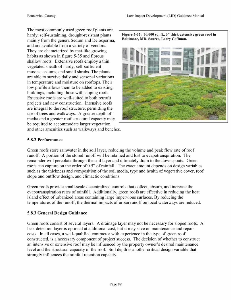
Brunswick County Low Impact Development (LID) Guidance Manual
Page 89
The most commonly used green roof plants are hardy, self-sustaining, drought-resistant plants mainly from the genera Sedum and Delosperma, and are available from a variety of vendors. They are characterized by mat-like growing habits as shown in figure 5-35 and fibrous shallow roots. Extensive roofs employ a thin vegetated sheath of hardy, self-sufficient mosses, sedums, and small shrubs. The plants are able to survive daily and seasonal variations in temperature and moisture on rooftops. Their low profile allows them to be added to existing buildings, including those with sloping roofs. Extensive roofs are well-suited to both retrofit projects and new construction. Intensive roofs are integral to the roof structure, permitting the use of trees and walkways. A greater depth of media and a greater roof structural capacity may be required to accommodate larger vegetation and other amenities such as walkways and benches.
5.8.2 Performance
Green roofs store rainwater in the soil layer, reducing the volume and peak flow rate of roof runoff. A portion of the stored runoff will be retained and lost to evapotranspiration. The remainder will percolate through the soil layer and ultimately drain to the downspouts. Green roofs can capture on the order of 0.5” of rainfall. The exact amount depends on design variables such as the thickness and composition of the soil media, type and health of vegetative cover, roof slope and outflow design, and climactic conditions. Green roofs provide small-scale decentralized controls that collect, absorb, and increase the evapotranspiration rates of rainfall. Additionally, green roofs are effective in reducing the heat island effect of urbanized areas containing large impervious surfaces. By reducing the temperatures of the runoff, the thermal impacts of urban runoff on local waterways are reduced.
5.8.3 General Design Guidance
Green roofs consist of several layers. A drainage layer may not be necessary for sloped roofs. A leak detection layer is optional at additional cost, but it may save on maintenance and repair costs. In all cases, a well-qualified contractor with experience in the type of green roof constructed, is a necessary component of project success. The decision of whether to construct an intensive or extensive roof may be influenced by the property owner’s desired maintenance level and the structural capacity of the roof. Soil depth is another critical design variable that strongly influences the rainfall retention capacity.
Figure 5-35: 30,000 sq. ft., 3” thick extensive green roof in
Baltimore, MD. Source, Larry Coffman.

Brunswick County Low Impact Development (LID) Guidance Manual
Page 90
Green roofs can be incorporated into new construction or as a retrofit to existing buildings. Though several site factors will need to be considered, such as the aspect of the roof, the microclimate of the site, prevailing winds and the building’s functions – most factors can be accommodated in an appropriate green roof design. Extensive green roof systems are composed of several layers. The roof systems may be modular interlocking components or each layer may be installed separately. Either way an extensive green roof is constructed with the following basic layers (starting at the bottom): structural support, a waterproof roofing membrane (including flashing), a root barrier, drainage, a filter fabric (for fine soils), growing medium (soil) and plant materials and mulch (see figure 5-36 and 5-37). Material for the growing medium must be weed seed free and the proper material and depth for the particular roof style. Generally, a building’s structure must be able to support an additional 10-25 pounds per square foot of weight, depending on the growth media and vegetation used. For new construction, the load requirement of the green roof can be addressed as part of the building’s design process. Additional structural support may be necessary for a retrofit project; however, many existing buildings are constructed with adequate structural support to accommodate a green roof. Green roofs can be designed by experienced architects, landscape architects, and building contractors. Green roofs may require maintenance beyond standard roof care, though such care is likely similar in cost. Long-term management should be factored into appropriate siting and design of green roofs. Extensive green roofs in the United States cost $10 to $20 per square foot for all use types (e.g., high density residential, commercial, and industrial). These costs include green roof components, including the waterproofing membrane, soil substrate, and planting. By far, the highest costs associated with green roof construction are the soil media and the specialized plants. Planting costs are higher if plants are installed individually rather than pre-grown on vegetation mats.
Figure 5-36 Typical green roof design elements.
Source, LID Center.
Figure 5-37 Typical green roof design cross-section.
Source, LID Center.

Brunswick County Low Impact Development (LID) Guidance Manual
Page 91
5.8.4 Applications and Advantages
Green roofs provide numerous environmental, economic and social benefits including:
• Absorbs rainfall at the source - 10-100% of roof runoff is absorbed and utilized by the vegetation (peak storm water flow rates are also reduced).
• Improves building insulation, thereby reducing heating and cooling costs and energy consumption.
• Reduces heat island effect and the associated effects on waterway temperatures.
• Increases wildlife habitat for birds and insects that is often scarce in urban areas.
• Absorbs noise pollution through soils, plants, and trapped layers of air.
• Reduces glare that affects adjacent buildings and habitat.
• Increases life-span of roof by as much as twice as long by protecting the roof’s structural elements from UV rays, wind and temperature fluctuations.
• Improves air quality by reducing air temperatures, filtering smog, binding dust particles, and converting carbon dioxide to oxygen through photosynthesis.
• Provides an attractive roof - in urbanized areas, green roofs integrate living systems into the built environment; in less urbanized areas, green roofs can help blend a structure into the surrounding landscape.
5.8.5 Limitations
• Initial costs can be prohibitive, especially for re-roofing a standard roof. However, extensive green roofs can be cost-competitive on a life cycle basis.
• Specific maintenance, such as irrigation and cleaning out drainage features will need to be factored into the long-term building maintenance schedule.
• Untraditional design and installation may prolong the permitting process.
• Green roof systems are still an evolving market and practice that may need economic or policy incentives to support further development.
5.8.6 Inspection and Maintenance Requirements
• Upon installation, the green roof system should be inspected monthly for the first year and after each large storm event for erosion, plant survival, proper drainage and water proofing.
• Inspections can be reduced to a quarterly schedule once the green roof system has proven to work properly and vegetation is established.
• If necessary, irrigate in short bursts only (3-5 minutes) to prevent runoff. Irrigation frequencies should be established by the designer using an automated system.
• Clean out drain inlets as needed.
• Weeding and mulching may be necessary during the establishment period, depending on the planting design.
• Replace or fill in vegetation as needed.
• Inspect soil levels semi-annually to ensure plant survival and rainfall absorption.

Brunswick County Low Impact Development (LID) Guidance Manual
Page 92
• If the vegetation used is flammable during the dry season, it should be mowed or watered as needed to prevent fire.
5.9 Stormwater Wetlands7
5.9.1 General
The most common reason a stormwater wetland is used on an LID site is the presence of high water tables in places where stormwater is most ably treated. Very few LID practices function appropriately when there is a shallow seasonal high water table. In these situations, a shallow backyard wetland is often the most appropriate BMP. The stormwater wetland should be designed so that it intersects the seasonal high water table and possibly also the seasonal low water table. If the difference between the seasonal high and seasonal low water table is substantial, then a drier stormwater wetland will be created, which is reasonable as long as plant selection reflects the hydrology.
5.9.2 General Design Guidance
Plants for backyard wetlands usually need to be aesthetically appealing and mosquito-resistant. Please see Appendix II for a list of appropriate plants for constructed wetlands. At normal pool Cattails (Typha spp.) are conspicuously absent from any constructed wetland plant list. While native, cattails are well adapted to develop monocultures that shelter mosquitoes from their predators. In short, if a stormwater wetland is to be located near a population center, such as a commercial center parking lot or a residential neighborhood, it is advised to keep cattail populations under control. If more than 15% of a stormwater wetland (that is located near people) is populated by cattails, it is recommended to remove the majority – if not all – of the cattails present. However, if stormwater wetlands are to be constructed in rural areas, such as along highways in eastern North Carolina, it is reasonable to allow cattail growth, as these plants are tolerant of relatively high pollutant loads and propagate easily. Stormwater wetlands do have evapotranspiration and infiltration losses. The exact amount of each has not been well quantified. As water ponds in a stormwater wetland immediately following a storm, the level of water is usually above that of the surrounding groundwater table. Along the perimeter of a stormwater wetland, some post-storm infiltration loss would be expected to occur. The volume of water lost from a given storm event would be the result of the height above the water table of the water ponded inside the wetland, the residence time of water inside the wetland, and the surrounding soil’s permeability.
7 This discussion of pocket wetlands is adapted from Hunt, et al. Draft NC LID Manual Chapter 6. February 2008 ver.
Figure 5-38: Performance of Constructed
Wetlands

Brunswick County Low Impact Development (LID) Guidance Manual
Page 93
There are evapotranspiration losses from the stormwater wetland between rainfall events. This amount varies by vegetation type and time of year. A preliminary study revealed that the amount of infiltration loss and evapotranspiration loss annually may range from 22 to 26% and 11 to 26%, respectively. One common concern among designers is the ability of shallow water plants to survive during a drought. As Figure 5-39 shows, once established, shallow water plants can tolerate being dry (i.e., not inundated) during drought periods. Remember that naturally occurring wetlands also become dry occasionally. In fact, wetting and drying cycles are key to the wetland’s ability to treat many pollutants effectively. Even during droughts, soils within the wetland remain moist within a foot of the surface. As long as wetland plant roots are able to reach these moist soils, the wetland plants can survive during droughts. A study was conducted in the mid 2000’s in North Carolina showing that, typically, mosquitoes were not present in high numbers at the majority of stormwater wetlands and wet ponds surveyed.8 However, it was found that mosquitoes can survive and thrive in wetlands with certain characteristics, namely overgrown by monocultures of cattails, heavily wooded, algal mats, and floatage/ debris. It was found that providing habitat for predators and keeping “mosquito habitat” to a minimum that mosquito populations can be mitigated. One major conclusion of the study was to design several small deep pools throughout a stormwater wetland. These pools are refugia for mosquito predators like Gambusia affinis (mosquito fish). If a stormwater wetland is quite small (such as many will be in LID applications) then either one deeper pool (18” of water) or none will be used. A second design recommendation was to include flowering species of vegetation that attract other mosquito predators like dragonflies.
5.9.3 Design and Maintenance Requirements
Some considerations unique to stormwater wetlands include:
• Excavation: If the water table to intersect is near the surface, then very little excavation is required.
• Plant spacing: Many designers desire the minimum spacing - plants on 36-inch centers. However, this spacing will leave the wetland with a barren look for at least a year, and opens the door to cattail infestation. A more densely planted wetland (e.g. one plant on
8
Hunt, W.F., C.S. Apperson, S.G. Kennedy, and W.G. Lord. 2005. Mosquito Control for Stormwater Facilities. NC
Cooperative Extension Publication # AG-588-4, Raleigh, NC.
Figure 5-39 A stormwater wetland in Durham during the
drought of 2002. Source, Larry Coffman.

Brunswick County Low Impact Development (LID) Guidance Manual
Page 94
24-inch centers) results in a better looking wetland in the short term. A tighter spacing usually results in less maintenance and unwanted species removal.
• Outlet Construction: Small “pocket” wetlands may have very simple outlets such as pre-treated lumber.
• Required Aesthetics: If the wetland is “front and center” it needs to be more attractive and therefore specific planting plans must be followed. Maintenance becomes more important.
In addition to design, stormwater wetlands must be maintained to keep mosquitoes from becoming a problem. Some common “mosquito maintenance” requirements include:
• Removing unwanted trees and shrubs: An abundance of woody species was found to provide a safe harbor for mosquitoes. It is reasonable to have a limited number of woody species (one recommendation 1 tree per 3,000 square feet of wetland) but others will volunteer.
• Removing cattails: Cattails, as discussed earlier, are very aggressive and can out-compete other vegetation if given enough time. Removing cattails as they arrive in the wetland is an annual to semi-annual process which need not be time consuming.
• Removing trash and other floatables: Pocket wetlands, like all BMPs, receive water from a larger watershed meaning that not only water comes to wetland, but everything in or carried by the water does, as well. Trash will inevitably collect in a wetland if there is a human population in or adjacent to the wetland’s drainage catchment. Floating trash provides mosquitoes an area free of many predators.
• Trash removal from outlet: In addition to being unsightly, trash can also clog a wetland’s outlet.9 A clogged outlet will necessarily raise the elevation of the water inside the wetland, which may cause desirable vegetation to die. Into these voids of dead vegetation the hardier species (like cattails) will take over.
5.10 Infiltration Trenches and Basins
For a thorough review of Infiltration Wells, Trenches and Basins, please see the Stormwater BMP Manual (NCDENR 2007). Many of the concepts discussed in the bioretention section of this chapter also apply to infiltration trenches and basins, particularly that deeper and oversized basins will “convert” a much higher faction of inflow to infiltration. Also, infiltration trench and basin hydrology is impacted by the geometry of the practice. Maximizing the perimeter to surface area ratio of the practice will improve the infiltration basin’s performance.
9 If the stormwater wetland treats a large enough watershed, there will be a rigorously designed outlet structure. Many small watershed wetlands (those treating less than 1 acre, for example) will not have an intensively designed outlet.
Figure 5-40: Performance of Infiltration
Basins and Trenches.

Brunswick County Low Impact Development (LID) Guidance Manual
Page 95
References Cahill, Tom. Sustainable Site Design – A PowerPoint Presentation presented at CASQA Conference 2006, September 25, 2006. Sacramento, California. Eisenman, Theodore. “Raising the Bar on Green Roof Design.” Landscape Architecture Magazine. November 2006: 22-29. Green Roofs for Healthy Cities. 2006. Website resource: http://www.greenroofs.net Rosenzweig, C., S. Gaffin, and L. Parshall, (Eds.) 2006. Green Roofs in the New York Metropolitan Region; Research Report. Columbia University Center for Climate Systems Research and NASA Goddard Institute for Space Studies. New York. 59 pages.
Hunt, W.F., C.S. Apperson, S.G. Kennedy, B.A. Harrison, and W.G. Lord. 2006b. Occurrence and relative abundance of mosquitoes in stormwater retention facilities in North Carolina, USA. Water Science and Technology, 52(6-7): 315-321.

Brunswick County Low Impact Development (LID) Guidance Manual
Page 96
Chapter 6. Putting LID into Practice
6.1 Introduction
LID involves the use of many practices. Each LID practice requires careful planning and careful construction. Even the best designs can result in failures if the LID practices are improperly constructed. Each LID practice has its own specific permitting and construction requirements. Many of these requirements are discussed in Chapter 5. This chapter deals with the more general permitting and construction issues that should be followed for a successful LID project.
6.2 Permitting LID Projects Using “LID-EZ”
Brunswick County, in a collaborative effort with New Hanover County, City of Wilmington, N.C. Coastal Federation and N.C. Division of Water Quality, has developed a stormwater management tool to aid engineers, planners, and developers with design and permitting of LID projects. The tool, LID-EZ, quantifies the effect of the structural and non-structural BMPs on the overall hydrology of residential and commercial developments. LID-EZ requires the user to enter basic pre and post development information into the software. The software then computes required storage volumes necessary to meet local and state stormwater regulations. The user then inputs all proposed structural storage devices and identifies the non-structural devices, such as disconnected impervious areas. The resulting calculations then quantifies the impacts of all LID components on the post development conditions as they relate to required water quality storage volumes and peak flow rates. While small scale structural and non-structural BMPs can be used to meet many state and local regulation, often the engineer or developer may need to incorporate additional storage areas to fully comply with the regulations. The importance and the benefit of the small scale LID devices cannot be overlooked. If a hybrid approach is used, LID-EZ should still be used to compute the effective post development curve numbers, which can then be used to determine actual volume requirements of the large scale detention structures. In many cases, the size of the large scale devices may be significantly reduced. If the user chooses to use a hybrid approach to stormwater management and include large structural BMPs, such as a wetland or wet pond, additional detention system routings and analysis may be required. LID-EZ is available free of charge from Brunswick County. Contact the Brunswick County Engineering Department for more information.

Brunswick County Low Impact Development (LID) Guidance Manual
Page 97
6.3 Constructing LID Projects
6.3.1 Training
It is very important that contractors, vendors and inspectors have been properly trained in the design specification and construction requirements for all LID practices employed. The success of many LID techniques depend on accurately following the grading plan; the use of proper materials and the appropriate location of practices. Due to the complexities of the practice, it may be necessary for vendors, contractors, and permitters to participate in certification training. For example, the design and construction of bioretention cells requires the knowledge of several disciplines including engineering, landscape architecture and soil science to ensure the proper design and construction of the project. North Carolina Cooperative Extension, through the N.C. State Biological and Agricultural Engineering Program, offers a stormwater BMP inspection and maintenance certification program. The purpose of the workshop is to offer instruction of BMP construction and maintenance activities. Professional development hours are offered for professional engineers and surveyors. More information about the certification program may be found at http://www.bae.ncsu.edu/stormwater or by contacting the N.C. State Biological and Agricultural Engineering Stormwater Program.
6.3.2 Communication LID uses innovative techniques, unique strategies and various combinations of practices. Consequently, each development results in a unique design with its own set of issues and challenges. It is vital that everyone involved in the LID project (contractors, vendors, design engineers and inspectors) understand the unique details of the LID project. A pre-construction meeting is the most useful approach to ensure that the project goals and issues are effectively communicated. Ideally the permit reviewer, contractor, vendor, design engineer and inspector should hold a meeting to go over the plans and discuss all aspects of the project. During the pre-construction meeting, the inspector may evaluate the proposed sequence of construction, sediment control requirements, and indicate when inspection points during construction of the LID practices are required as identified in the design manual. Throughout the construction process, there must be effective communication. No construction project takes place without unforeseen problems and the need to make some field adjustments. Proper lines of communication must be in place throughout the construction phase between the general contractor, site engineer, inspector, and permit staff to address required changes. After construction, a final inspection and walk-through of each LID practice is necessary to ensure its proper function.
6.3.3 Erosion and Sediment Control One of the major advantages to an LID design is that it allows for clearing and grading in stages. Since LID can be a lot-specific approach to stormwater management it is not necessary to completely clear-cut and regrade the site to establish the drainage system. A development can be

Brunswick County Low Impact Development (LID) Guidance Manual
Page 98
constructed on a lot-by-lot basis. This can greatly reduce the amount of sediment generated thus reducing possible damage to LID designated areas. Proper erosion and sediment control during construction is vital for LID practices. If existing vegetation is to be used for treatment (bioretention, swales or buffers), then these areas must be protected from sedimentation. A thin layer of sediment over the root system is enough to suffocate a plant or tree. Additionally, areas that may be used for infiltration must be protected to prevent sediment from clogging soils with silts and clays. Preventing damage from sedimentation is less expensive than cleaning or rehabilitating an area.
6.3.4 Tree Protection Care must be taken to protect tree conservation areas during construction. Tree conservation areas are ineffective if the trees die shortly after the project is completed. Trees can be damage in a number of ways during the construction process. It is important to consider the following during any construction process.
• All types of construction equipment can cause mechanical injury to roots, trunks or branches. This can weaken a tree’s resistance to a number of diseases and insect infestation. Trees should be clearly marked and given wide clearance. Excavation around trees should not be within the drip line of the tree.
• Soil compaction squeezes the air and water out of the soil making it difficult for a tree to absorb oxygen and water. No construction equipment should be allowed to run over the roots within the drip line of the tree.
• Grading practices that deposit soil over the roots of trees eventually suffocates those roots. More than an inch or two of soil over the roots is enough to potentially suffocate the roots of trees and compromise the health of the tree.
• Grading practices that divert too much runoff to a mature stand of trees can result in damage. As a tree matures its ability to adapt to changes decreases. Additionally, if a stand of trees is located in a normally dry area that suddenly becomes very wet, the additional water may kill the trees. An arborist should be consulted these situations to determine the trees’ tolerance to a change in hydrology.
• A tree protection plan with written recommendations for the health and long-term welfare of the trees during the pre-construction, demolition, construction, and post-construction development phases, should be developed. The tree protection plan should include specifics about avoiding injury, information about treatment for damage and specifics about required inspections of protected trees. The tree protection plan should also provide information about caring for damaged trees.
6.3.5 Construction Sequence Construction sequencing is important to avoid problems while constructing LID projects. Proper sequencing decreases the likelihood of damage to the BMP during construction and helps to ensure optimal performance of the BMP. Each LID practice is somewhat different, therefore information should be provided to the contractor on the proper sequencing.

Brunswick County Low Impact Development (LID) Guidance Manual
Page 99
Conservation areas must be identified and protected before any major site grading takes place. Most of the engineered LID practices (bioretention, infiltration trenches, and infiltration swales) should be constructed at the end of the site development process, and preferably when most of the site is stabilized. Any LID practice that relies on filtration or infiltration must be protected throughout the construction phase from sedimentation and should not be activated until the contributing drainage area is stabilized. For example, bioretention areas should be constructed at the time of final grading and landscaping, and these areas should be protected from sedimentation until the drainage routes to the facility are stabilized.
6.3.6 Construction Administration Proper oversight is important to the success of an LID design. Each engineered LID practice should be inspected at the time of installation. The general contractor should have their engineer on site during critical periods during the construction process, and the site manager should follow up with the engineer to ensure proper installation. Inspectors not only need to be well-informed about design and construction speciation of all LID techniques, they also need adequate enforcement tools. Occasionally, it is necessary to stop work and force contractors and vendors to remove and replace improper materials or install practices. It may not be possible to have the project manager on site at all times to make field adjustments. Therefore, it may be necessary to empower inspectors with the ability to make minor field adjustments in order to prevent unnecessary construction delays.
6.4 Maintenance
As with any stormwater management technique, maintenance is essential with LID BMPs to ensure that the designed stormwater benefits continue. Post-construction inspections and maintenance are important to ensure that each technique is functioning effectively. Annual inspections are recommended, with more frequent inspections during the first year to ensure that vegetation is thriving. Inspection and maintenance of structural LID practices such as cisterns, vegetated roofs, permeable pavements, infiltration structures, and manufactured proprietary devices should follow local health department, state or local stormwater minimum standards, as well as manufacturer’s recommendations for maintenance or repair. Any under-drains or outfall structures should be inspected on a regular basis and cleaned out or repaired as necessary. The primary maintenance requirement for vegetative LID structural and non-structural practices is inspection and periodic repair or replacement of the treatment area’s components. This often includes the maintenance of the vegetative cover (pruning), replacing mulch, removing weeds, and possibly removing sediment to preserve the practice’s hydraulic properties. For many LID practices, this generally involves little more than the routine periodic landscape type maintenance. Maintenance requirements are further discussed in Chapter 5 with each associated LID technique.

Brunswick County Low Impact Development (LID) Guidance Manual
Page 100
To ensure continued long-term maintenance, all affected landowners should be made aware of their individual or collective maintenance responsibilities through legal instruments such as agreements and maintenance easements that convey with the property. Outreach materials, such as LID brochures or fact sheets that explain the function of practices and the anticipated maintenance responsibilities of homeowners, should be included in settlement or homeowner association documents. The developer should prepare a maintenance plan that provides clear guidance and instructions to the property owner, property manager, or property owners association about the annual maintenance needs of each LID technique. Maintenance Agreement The developer should record and reference on the recorded plat, a maintenance agreement, or restrictive covenant that sets forth the continuing responsibilities of the property owners association or lot owner for maintenance, including specifying how cost will be apportioned among lot owners when maintenance is provided by a homeowners association. The maintenance agreement should provide that the association and its individual members are jointly and severally liable for maintenance (see Appendix I for an example of an maintenance agreement). Maintenance Easements Where necessary the developer must record easements for access, maintenance, and inspections by any property owners association and by the regulating jurisdiction. Where natural features and conservation practices are used the maintenance easement should also include conservation easements with appropriate limitations to restrict destruction of the conservation areas.

Appendix I
Sample Maintenance Agreement

Brunswick County Low Impact Development (LID) Guidance Manual
Appendix I - 1
Return to: Thomas L. Horstman, CPESC Erosion Control Supervisor New Hanover County 230 Government Center Drive
NORTH CAROLINA WAKE COUNTY
STORMWATER CONTROL STRUCTURE AND ACCESS EASEMENT AND AGREEMENT (Corporate)
THIS STORMWATER CONTROL STRUCTURE AND ACCESS EASEMENT
AND AGREEMENT, made this day ___ of ____________, 20___, (DATE OF AGREEMENT) by 2 (NAMEOF OWNER), a North Carolina corporation whose principal address is 2a , (hereafter “Grantor”), with, to, and for the benefit of the Town of Cary, a municipal corporation of the State of North Carolina, whose address is P.O. Box 8005, Cary North Carolina 27512-8005 (hereinafter “Grantee” or “Town”).
W I T N E S S E T H:
WHEREAS, Grantor is the owner in fee simple of certain real property, situated in the Town of Cary, County of Wake, North Carolina and more particularly described as follows:
3 (LEGAL DESCRIPTION OF PROPERTY)
It being the same land conveyed to the Grantor by deed recorded in Book 3a at
page 3a in the Office of the Register of Deeds for Wake County (hereafter referred to as “Property”); and
WHEREAS, the property is located within the planning jurisdiction of the Town of Cary, and is subject to certain requirements set forth in the Land Development Ordinance of the Town, (hereafter “Cary LDO”), as such may be amended from time to time; and
WHEREAS, one of the conditions for development of Property is the granting or dedication of a Stormwater Control Structure easement, which includes the implementation of certain stormwater practices such as, but not limited to, the construction, operation and maintenance of engineered stormwater control structure(s) as provided in Cary LDO; the dedication of an access easement for inspection and maintenance of the Stormwater Control Structure easement area and engineered structures; and the assumption by Grantor of certain specified maintenance and repair responsibilities; and

Brunswick County Low Impact Development (LID) Guidance Manual
Appendix I - 2
WHEREAS, this Easement and Agreement has been procured in accordance
with the requirements of N.C. G.S. Sec 143-211 et. seq. and Chapter 4, Part 4.6 of the Cary LDO.
NOW, THEREFORE, for a valuable consideration, including the benefits Grantor may derive therefrom, the receipt of which is hereby acknowledged, Grantor has dedicated, bargained and conveyed and by these presents does hereby dedicate bargain, sell, grant and convey unto the Grantee, its successors and assigns, a perpetual, and irrevocable right and easement in, on, over, under, through and across Property (1) for a STORMWATER CONTROL STRUCTURE easement (“hereafter SCS Easement”) of the nature and character and to the extent hereinafter set forth, more particularly shown and described on Attachment 4 (NAME OF AS BUILT DRAWING) which is attached hereto and incorporated herein by reference; upon which Grantor shall construct, maintain, repair and reconstruct stormwater control structure(s), including detention pond(s), pipes and water control structures, berms and dikes, and shall establish and maintain vegetative filters and groundcovers; and (2) an access easement more particularly shown and described on Attachment 4a (ATTACHMENT NUMBER 1 OR 2), , for the purpose of permitting Town inspection and, if necessary, maintenance and repair of the SCS Easement and engineered structure(s) as more fully set forth herein and in Cary LDO.
The terms, conditions, and restrictions of the Stormwater Control Structure Easement and Access Easement are: 1. The requirements pertaining to the SCS Easement are more fully set forth in Chapter Chapter 4, Part 4.6 of Cary LDO and the ”Operation and Maintenance Manual for 5 (hereafter “Operations and Maintenance Manual”), Cary, NC, prepared by 5a, and dated 5b a copy of which is on file in the Town of Cary Engineering Department. Grantor further agrees Grantor shall perform the following, all at its sole cost and expense: I. Monthly or after every runoff producing rainfall, whichever comes first:
a. Remove debris from trash rack. b. Check and clear orifice of any obstructions. c. Check pond side slopes; remove trash, repair eroded areas before next d. rainfall.
II. Quarterly
a. Inspect the collection system (i.e., catch basin, piping, grassed swales) for proper functioning. Clear accumulated trash from basin grates, and basin bottoms, and check piping for obstructions.
b. Check pond inlet pipes for undercutting. Repair if necessary. c. Repair any broken pipes. d. Replace rip rap that is choked with sediment.

Brunswick County Low Impact Development (LID) Guidance Manual
Appendix I - 3
e. Reseed grassed swales twice yearly. Repair eroded areas immediately. III. Semi-Annually
a. Remove accumulated sediment from bottom of outlet structure. b. Check available ponding depths at several locations. If depths are reduced to
75% of original design depths, remove sediment to original design depth. IV. General
a. Mow side slopes according to the season and species of vegetation. b. Cattails and other invasive species shall be removed when they cover the
entire surface area of bioretention area. c. All components of the engineered structures are to be kept in good working
order. d. In case the ownership of the Stormwater Control Structure transfers, the
current owner shall, within thirty (30) days of transfer of ownership, notify the Town of Cary Engineering Department, Stormwater Management Division of such ownership transfer.
e. This property and structure are also subject to the Operation and Maintenance Manual filed with the register of deeds.
2. Grantor represents and warrants that Grantor is financially responsible for construction, maintenance, repair and replacement of all stormwater control structures, appurtenances and vegetation, including the impoundment. Grantor agrees to perform the maintenance as outlined above and in the Operations and Maintenance Manual in consideration of the Certificate of Compliance with stormwater regulations received for Property. 3. If Grantor fails to comply with these requirements, or any other obligations imposed herein, in Cary LDO or Operations and Maintenance Manual the Town of Cary may perform such work as Grantor is responsible for and recover the costs thereof from Grantor. 4. This Easement and Agreement gives the Grantee the following affirmative rights: Grantee, its officers, employees, and agents may enter Stormwater Control Structure and Access Easement whenever reasonably necessary for the purpose of inspecting same to determine compliance herewith, to maintain same and make repairs or replacements to the engineered stormwater control structure(s) and appurtenances and conditions as may be necessary or convenient thereto in the event Grantor defaults in its obligations and to recover from Grantor the cost thereof, and in addition to other rights and remedies available to it, to enforce by proceedings at law or in equity the rights, covenants, duties, and other obligations herein imposed.
The Grantor shall in all other respects remain the fee owner of Property and area subject to these easements, and may make all lawful uses of Property not inconsistent

Brunswick County Low Impact Development (LID) Guidance Manual
Appendix I - 4
with these easements.
The Grantee does not waive or forfeit the right to take action to ensure compliance with the terms, conditions and purposes of this Easement and Agreement by a prior failure to act.
The Grantor agrees that the terms, conditions and restrictions of this easement will be inserted by Grantor in any subsequent deed or other legal instrument by which he divests himself of either the fee simple title to or possessory interests in the subject property. The designation Grantor and Grantee shall include the parties, their heirs, successors and assigns.
TO HAVE AND TO HOLD the aforesaid rights, privileges, and easements herein granted to the Grantee, its successors and assigns forever and the same Grantor does covenant and that Grantor is seized of said premises in fee and has the right to convey the same, that except as set forth below the same are free from encumbrances and that Grantor will warrant and defend the said title to the same against claims of all persons whosoever.
The covenants agreed hereto and the conditions imposed herein shall be binding upon the Grantor and its agents, personal representatives, heirs and assigns and all other successors to Grantor in interest and shall continue as a servitude running in perpetuity with the above described land.
IN WITNESS WHEREOF, the Grantor has caused this instrument to be signed in its corporate name by its duly authorized officers and its seal to be hereunto affixed by authority of its Board of Directors, the day and year first above written.
________________________ (Grantor)
________________________
President Attest: _________________________ __________Secretary (Corporate Seal) NORTH CAROLINA WAKE COUNTY I, the undersigned Notary Public, do hereby certify and State aforesaid, do hereby certify that personally appeared before me this day and acknowledged the execution of the foregoing instrument.

Brunswick County Low Impact Development (LID) Guidance Manual
Appendix I - 5
Witness my hand and official seal this ____day of__________________ , 20____ . My commission expires_______________________:
_____________________________________ Notary Public
[Official Seal] ckc Easement&Deed/Corporate.doc

Appendix II
Suggested Plant List
Contents
Plants for Rain Gardens
Wetland Plants for Coastal NC

Brunswick County Low Impact Development (LID) Guidance Manual
Appendix II - 1
Plants for Rain Gardens Recommended for Southeastern North Carolina
Charlotte Glen, Urban Horticulture Agent,
North Carolina Cooperative Extension –Pender County Center Soil conditions in rain gardens alternate between wet and dry, making them tough places for many plants to grow. The following plants are adapted to these conditions, though some plants will tolerate more moisture than others. Each plant is marked according to its flooding tolerance, with 3’s being tolerant of longer flooding, 2’s only tolerating brief flooding, and 1’s indicate plants that tolerant extended drought once established. All of these plants are native to the southeastern United States in wetland habitats and most are readily available at local nurseries. Wetland plants can generally grow well in moist or well-drained soils, whereas plants adapted to dry soils rarely survive in soggy conditions. How wet a rain garden stays will vary considerably depending on the site where it is installed. Rain gardens created on sandy soils will rarely hold water for more than a few hours. On these sites it is most important to choose plants for their drought tolerance. Rain gardens created on loamy or silty soils could pond water for 1-2 days (if your site ponds water for more than 3 days, you should consider creating a wetland). On these sites, choosing plants tolerant of extended flooding is critical to success. Remember you are not limited to planting just within the excavated area! Extending plantings around this area will help the rain garden to blend in with the overall landscape. Any plants adapted to the site conditions can be used outside of the excavated area. For more information on designing rain gardens and bioretention areas, refer to the following NCSU publication: Designing Rain Gardens (Bioretention Areas), available from your local NC Cooperative Extension office or online at: http://legacy.ncsu.edu/classes-a/bae/cont_ed/bioretention/lecture/design_rain.pdf
North Carolina State University and North Carolina A&T University commit themselves to positive action to secure equal
opportunity regardless of race, color, creed, national origin, religion, sex, age, veteran status, or disability. In addition, the two
Universities welcome all persons without regard to sexual orientation. North Carolina State University, North Carolina A&T
University, U.S. Department of Agriculture, and local governments cooperating.

Brunswick County Low Impact Development (LID) Guidance Manual
Appendix II - 2
Large Trees (over 30’ tall)
Deciduous
Red Maple (2) – Acer rubrum River Birch (1,3) – Betula nigra
Green Ash (3) – Fraxinux pennsylvanica Black Gum (2) – Nyssa sylvatica
Willow Oak (1,2) – Quercus phellos Willows (3) – Salix species
Bald Cypress (1,3) – Taxodium distichum Pond Cypress (1,3) - Taxodium ascendens
Nutall Oak (1,2) – Quercus nuttalii
Evergreen
Atlantic White Cedar (1,3) – Chamaecyparis thyoides Southern Magnolia (1,2) – Magnolia grandiflora
Longleaf Pine (1,2) – Pinus palustris Swamp Laurel Oak (3) – Quercus laurifolia
Small Trees (under 30’ tall)
Deciduous
Red Buckeye (2) – Aesculus pavia Ironwood (1,3) – Carpinus caroliniana
Redbud (1,2) – Cercis canadensis Fringe Tree (2) – Chionanthus virginicus
Washington Hawthorn (3) – Crataegus phaenopyrum Possumhaw (1,3) - Ilex decidua
Evergreen
Dahoon Holly (1,2) – Ilex cassine American Holly (1,2) – Ilex opaca
Red Cedar (1,2) – Juniperus virginiana Sweet Bay (3) – Magnolia virginiana
Devilwood (1,2) – Osmanthus americanus Red Bay (1,2) – Persea borbonia
Evergreen shrubs that can be grown as small trees include Yaupon, Wax Myrtle, and Anise Shrub.
Shrubs
Deciduous
Chokeberry (1,3) – Aronia arbutifolia Beautyberry (2) – Callicarpa americana Sweet Shrub (2) – Calycanthus floridus

Brunswick County Low Impact Development (LID) Guidance Manual
Appendix II - 3
Buttonbush (3) – Cephalanthus occidentalis Pepperbush (2) – Clethra alnifolia
Strawberry Bush (2) – Euonymous americanus Fothergilla (2) – Fothergilla gardenii
Winterberry (3) – Ilex verticillata Virginia Willow (3) – Itea virginica
Spicebush (2) – Lindera benzion Possumhaw (3) – Viburnum nudum
Dusty Zenobia (2) – Zenobia pulverulenta
Evergreen
Florida Leucothoe (2) – Agarista populifolia Inkberry (2) – Ilex glabra
Yaupon (1,2) – Ilex vomitoria Florida Anise Shrub (3) – Illicium floridanum
Anise Shrub (1,2) – Illicium parviflorum Coastal Leucothoe (2) – Leucothoe axillaris
Wax Myrtle (1,2) – Myrica cerifera Dwarf Palmetto (3) – Sabal minor
Perennials Blue Star (3) – Amsonia tabernaemontana
Lady Fern (2) – Athyrium felix-femina Butterflyweed (1) – Asclepias tuberosa
Swamp Milkweed (3) – Asclepias incarnata Climbing Aster (3) – Aster carolinianus
False Indigo (1,2) – Baptisia species Boltonia (3) – Boltonia asteriodes Turtlehead (3) – Chelone glabra
Green and Gold (2) – Chrysongonum virginianum Mouse Ear Coreopsis (2) – Coreopsis auriculata
Tickseed (1,2) – Coreopsis lanceolata Swamp Coreopsis (2) – Coreopsis rosea Joe Pye Weed (3) – Eupatorium dubium
Swamp Sunflower (3) – Helianthus angustifolius Swamp Mallow (3) – Hibiscus moscheutos
Texas Star (3) – Hibiscus coccineus Blue Flag Iris (3) – Iris virginica
Seashore Mallow (3) – Kosteletskya virginica Gayfeather (2) – Liatris spicata
Cardinal Flower (3) – Lobelia cardinalis Cinnamon Fern (3) – Osmunda cinnamomea
Royal Fern (3) – Osmunda regalis Garden Phlox (2) – Phlox paniculata Moss Pinks (1,2) – Phlox subulata
Rudbeckia (1,2) – Rudbeckia fulgida

Brunswick County Low Impact Development (LID) Guidance Manual
Appendix II - 4
Green Headed Coneflower (3) – Rudbeckia laciniata Goldenrod (3) – Solidago rugosa Stoke’s Aster (2) – Stokesia laevis
Ironweed (3) – Vernonia novaboracensis Verbena (1,2) – Verbena canadensis
Ornamental Grasses River Oats (1,3) – Chasmanthium latifolium Muhly Grass (1,2) – Muhlenbergia capillaris
Panic Grass (1,3) – Panicum virgatum Indiangrass (1,2) – Sorghastrum nutans
Sedges and Rushes Lurid Sedge (3) – Carex lurida
Fringed Sedge (3) – Carex crinita Southern Waxy Sedge (3) – Carex glaucescens
White-topped Sedge (3) – Rhynchospora latifolia Woolgrass (3) - Scirpus cyperinus
Non-native perennials and ornamental grasses suitable for rain gardens include: Liriope (1,2) (Liriope muscarii and L. spicata), Siberian Iris (2) (Iris sibirica), Daylily (1,2) (Hemerocallis hybrids), Rain Lilies (3) (Zephyranthes species), Crinum Lilies (3) (Crinum species), Japanese
Painted Fern (2) (Athyrium nipponicum) and Maiden Grass (1,2) (Miscanthus cultivars).
1 Plants that, once established*, can withstand considerable drought (3-4 weeks
without rainfall)
2 Plants that grow best in moist to average soils and will only tolerate short periods
(1-2 days) of flooding.
3 Plants that will tolerate longer periods of flooding (3-5 days), but will also grow in
moist to average soils.
*Establishment usually takes 1-2 years for trees and shrubs and 1 year for perennials.
For more detailed information and images of each plant, visit the Plant Fact Sheets available
on NCSU’s Urban Horticulture website: www.ncstate-plants.net
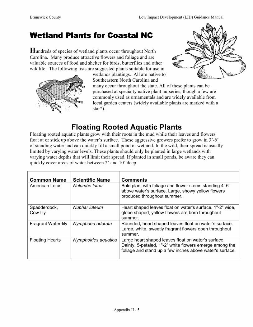
Brunswick County Low Impact Development (LID) Guidance Manual
Appendix II - 5
Wetland Plants for Coastal NCWetland Plants for Coastal NCWetland Plants for Coastal NCWetland Plants for Coastal NC
Hundreds of species of wetland plants occur throughout North
Carolina. Many produce attractive flowers and foliage and are valuable sources of food and shelter for birds, butterflies and other wildlife. The following lists are suggested plants suitable for use in
wetlands plantings. All are native to Southeastern North Carolina and many occur throughout the state. All of these plants can be purchased at specialty native plant nurseries, though a few are commonly used as ornamentals and are widely available from local garden centers (widely available plants are marked with a star*).
Floating Rooted Aquatic Plants Floating rooted aquatic plants grow with their roots in the mud while their leaves and flowers float at or stick up above the water’s surface. These aggressive growers prefer to grow in 3’-6’ of standing water and can quickly fill a small pond or wetland. In the wild, their spread is usually limited by varying water levels. These plants should only be planted in large wetlands with varying water depths that will limit their spread. If planted in small ponds, be aware they can quickly cover areas of water between 2’ and 10’ deep.
Common Name
Scientific Name
Comments
American Lotus Nelumbo lutea Bold plant with foliage and flower stems standing 4'-6' above water's surface. Large, showy yellow flowers produced throughout summer.
Spadderdock, Cow-lily
Nuphar luteum Heart shaped leaves float on water's surface. 1"-2" wide, globe shaped, yellow flowers are born throughout summer.
Fragrant Water-lily Nymphaea odorata Rounded, heart shaped leaves float on water’s surface. Large, white, sweetly fragrant flowers open throughout summer.
Floating Hearts Nymphoides aquatica Large heart shaped leaves float on water's surface. Dainty, 5-petaled, 1"-2" white flowers emerge among the foliage and stand up a few inches above water's surface.

Brunswick County Low Impact Development (LID) Guidance Manual
Appendix II - 6
Emergent Aquatic Perennials This group of plants prefers to grow in 3” to 6” of standing water, with their crowns and roots in the mud but their leaves and flowers emerging up above the water. They can tolerate periods of dryer conditions but in general need saturated soils to grow best. They are perfect for growing at the edges of ponds or in shallow standing water.
Common Name
Scientific Name
Exposure
Comments
Duck Potato* Sagittaria latifolia sun to light shade
Tough emergent aquatic with arrowhead shaped leaves and spikes of white flowers produced throughout summer. Reproduces rapidly.
Arrow Arum Peltandra virginica sun to part shade
Elegant arrowhead shaped leaves and interesting green flowers on a clump forming plant.
Pickerelweed* Pontederia cordata sun to part shade
Upright plant producing numerous 3' tall spikes topped with blue flowers all summer. Tough and attractive.
Lizard's Tail* Saururus cernuus sun to part shade
Spreading perennial that will grow in shallow standing water and wet soils. Pendant spikes of white flowers in late spring and summer.
Blue Flag* Iris virginica sun to part shade
Blue flowering, 3' tall iris that prefers to grow in shallow standing water or water's edge.
Submerged and Free Floating Aquatics Like floating rooted aquatics, these two types of aquatic plants require pools of permanently standing water to grow successfully. Though they are not necessary for the success wetland planting, their inclusion will certainly add interest and increase habitat value. Submerged plants grow completely underwater, though some do produce small flowers that float at the water’s surface. They help to keep the water oxygenated and provide habitat for fish. Examples of native submerged aquatics include Eelgrass (Vallisneria americana), Coontail (Ceratophyllum demersum), and Common Water Nymph (Najas guadalupensis). Free floating aquatics float on top of the water with their roots hanging down into the water below. These plants tend to increase rapidly and can quickly cover the surface of a pond or wetland. Native species include Carolina Water Fern (Azolla caroliniana) and Bladderwort (Utricularia inflata).
CAUTION: Extreme care should be taken when introducing free-floating aquatics so that
only native species are used. Many invasive non-native species are available that are or could
become noxious weeds.

Brunswick County Low Impact Development (LID) Guidance Manual
Appendix II - 7
Sedges and Rushes This large family of grass like plants includes many different moisture loving species. Most will grow happily in shallow standing water or permanently moist soils, though many can tolerate periods of dryer conditions. Sedges and rushes should be used as fillers in the backyard wetland. They are excellent for stabilizing soil and can be used in large sweeps for visual interest. Some of the more attractive species are listed below.
Common Name Scientific Name Comments Hop Sedge Carex lupulina 2'-3' tall sedge producing dramatic clusters of
pineapple shaped light green flowers in early summer.
Soft Rush Juncus effusus Common rush found throughout NC. 2'-3' tall with dark green spiky foliage. Green flowers age to brown seed pods throughout summer.
White-top Sedge Rhynchospora latifolia Showy 2' tall, spreading sedge bearing attractive white bracted flowers throughout summer.
Woolgrass Scirpus cyperinus Large, 3'-4' tall and wide clump forming bulrush producing wooly green flower heads in summer that age to an attractive rusty brown as seeds mature.
Moisture Loving Perennials Many of our most attractive native perennials grow in moist soils or wetlands. These plants return year after year to bring color and seasonal variety to wetlands areas. The flowers of many are excellent nectar sources for butterflies and hummingbirds. Some of these plants increase rather quickly by spreading roots known as rhizomes and stolons while others tend to stay in one place forming large clumps. The growth habit of each is noted below, as well as the average mature size (height x width).
Common Name
Scientific Name
Size
Exposure
Growth
Comments
Swamp Milkweed*
Asclepias incarnata 3'-4' x 2'-3'
sun - part shade
clumping Pink flowers in early summer. Larval host food of monarch butterflies.
Turtlehead Chelone glabra 3' x 3' sun - part shade
spreading Fall bloomer with spikes of white snapdragon shaped flowers.
Swamp Tickseed Coreopsis helianthoides
2'-3' x 2'-3'
sun - part shade
spreading Fall bloomer producing masses of golden sunflower shaped blossoms.

Brunswick County Low Impact Development (LID) Guidance Manual
Appendix II - 8
Common Name
Scientific Name
Size
Exposure
Growth
Comments
Plume Grass Erianthus giganteus 7'-10' x 3'-5'
sun - light shade
clumping Dramatic tall grass with showy flower plumes in fall.
Hatpins, Pipewort Eriocaulon decangulare
1'-2' x 1'-2'
sun - light shade
clumping Small white ball shaped flowers on the end of straight stems actually do resemble hatpins. Flowers all summer.
Joe Pye Weed* Eupatorium fistulosum
5'-7' x 3'-4'
sun - part shade
spreading Masses of rosy-mauve flowers in late summer through fall, attracts hundreds of butterflies.
Swamp Sunflower*
Helianthus angustifolius
5'-7' x 3'-4'
sun - part shade
spreading 6’ + towers topped with 3" wide golden sunflowers in fall - attracts butterflies.
Red Star Hibiscus*
Hibiscus coccineus 4'-6' x 3'-4'
sun - part shade
clumping Tough, clump forming, sturdy plant with star shaped red flowers in summer.
Rose Mallow* Hibiscus moscheutos
4'-6' x 3'-4'
sun - part shade
clumping Tough, durable plants with huge white, pink or rose flowers in summer.
Seashore Mallow Kosteletskya virginica
4'-6' x 3'-4'
sun - part shade
clumping Tall airy plants are covered with 2"-3" pink flowers all summer.
Cardinal Flower* Lobelia cardinalis 2'-4' x 1'-2'
sun - part shade
clumping Tall spikes of crimson red flowers in late summer and fall - attracts hummingbirds and butterflies .
Cinnamon Fern Osmunda cinnamomea
3'-5' x 2'-3'
sun - part shade
clumping Dramatic clump forming fern with rusty fiddleheads in spring.
Royal Fern Osmunda regalis 3'-5' x 2'-3'
sun - part shade
clumping Dramatic clump forming fern with bold textured foliage.
Switch Grass Panicum virgatum 3'-4' x 2'-3'
sun - part shade
spreading Upright fall blooming grass whose airy seedheads persist through winter.
Green Headed Coneflower
Rudbeckia laciniata 4'-6' x 3'-4'
sun - part shade
clumping Yellow flowers in summer on tall plants. Good for butterflies.
Goldenrod Solidago rugosa 3'-5' x 2'-3'
sun - part shade
spreading Multiple spikes of golden yellow flowers in late summer and fall.
Ironweed Vernonia noveboracensis
5'-7' x 3'-4'
sun - part shade
spreading Royal purple flowers atop tall stems in late summer through fall - attracts butterflies.

Brunswick County Low Impact Development (LID) Guidance Manual
Appendix II - 9
Common Name
Scientific Name
Size
Exposure
Growth
Comments
Atamasco Lily Zephyranthes atamasco
1' x 1' sun - part shade
clumping Spring bloomer with large white trumpet shaped flowers. Grows from bulbs.
* = Denotes plants that are commonly available at local garden centers.
Moisture Loving Woody Plants Woody plants are a valuable component of a any wetland, providing shelter for nesting birds, berries for wildlife, and large root systems that hold soil in place. The various wetlands that are found across our state are inhabited by many different species of trees and shrubs. Most of these plants are tough and adaptable, tolerating periods of flooding as well as drier conditions. Many will grow just as happily in average, well-drained soil as they will in wet boggy areas. The majority are deciduous plants (D) that loose their leaves each fall but a few are evergreen (E). The mature size is listed as height (H) x width (W).
Trees
Common Name Scientific Name E/D Exposure H x W Comments
Red Maple* Acer rubrum D sun to light shade
40'-60' x 20'-30'
Medium to large tree with excellent fall color. Produces showy red flowers and seedpods in early spring.
Pawpaw Asimina triloba D sun to part shade
15'-25' x 10'-20'
Suckering multi-stemmed shrub or small tree producing sweet banana like fruit in autumn.
River Birch* Betula nigra D sun to light shade
30'-40’ x 15'-20'
Adaptable tree that produces attractive light colored flaky bark. Often grows with multiple trunks.
Redbud* Cercis canadensis D sun to part shade
15'-25' x 10'-20'
Graceful small tree producing bright rosy purple flowers in early spring.
Atlantic White Cedar
Chamaecyparis thyoides
E sun to light shade
30'-50' x 10'-20'
Tall, slender evergreen formerly used to make log cabins. Smaller growing selections are available.
Fringe Tree Chionanthus virginicus
D sun to part shade
10'-20' x 10'-15'
Large shrub or small multi-stemmed tree bearing fragrant, white flowers in early summer, followed by blue berries on female plants.
Swamp Dogwood Cornus foemina D sun to part shade
15'-25' x 10'-20'
Large shrub or small multi-stemmed tree producing flat clusters of white flowers followed by blue berries. Excellent food source for birds.
TiTi Cyrilla racemiflora Semi E
sun to part shade
10'-20' x 10'
Large shrub or small multi-stemmed tree producing masses of tiny white flowers in drooping spikes in mid summer.
Possumhaw Ilex decidua D sun to light shade
15'-25' x 10'-20'
Small tree whose stems are lined with bright red berries in fall and winter.

Brunswick County Low Impact Development (LID) Guidance Manual
Appendix II - 10
Common Name Scientific Name E/D Exposure H x W Comments
Sweetbay* Magnolia virginiana Semi E
sun to light shade
20'-30' x 10'-15'
Small tree with large, fragrant white flowers in early summer. Often grows with multiple trunks.
Swamp Redbay Persea palustris E sun to part shade
20'-30' x 10'-15'
Evergreen upright tree. Salt tolerant and deer resistant.
Pond Cypress Taxodium ascendens
D sun to light shade
60'-70' x 10'-20'
Columnar habit with fine textured, feathery foliage. Rusty brown fall color.
Bald Cypress* Taxodium distichum
D sun to light shade
50'-70' x 20'-30'
Majestic large tree, synonymous with Southern swamps. Amazingly adaptable and will grow in almost any soil and up to 3' of standing water.
* = Denotes plants that are commonly available at local garden centers.
Shrubs Common Name Scientific Name E/D Exposure H x W Comments Chokeberry Aronia arbutifolia D sun to light
shade 6'-10' x
3'-5' Upright, suckering shrub producing flat cluster of white flowers in early spring - followed by generous clusters of bright red berries in fall and winter.
Beautyberry Callicarpa americana
D sun to part shade
4'-6' x 3'-5'
Striking clusters of magenta berries line stems in late summer and fall. Best cut back to 1' in early spring.
Sweet Shrub Calycanthus floridus
D sun to part shade
5'-8' x 5'-8'
Suckering shrub bearing fragrant maroon flowers in early summer.
Buttonbush Cephalanthus occidentalis
D sun to light shade
6'-12' x 6'-12'
Interesting round clusters of small white flowers in summer attract many butterflies. Adaptable - will grow in standing water or well drained soil.
Pepperbush, Summersweet*
Clethra alnifolia D sun to light shade
4'-6' x 3'-5'
Suckering shrub with extremely fragrant spikes of white or pink flowers in summer and yellow autumn color.
Silky Dogwood Cornus amomum D sun to part shade
6'-10' x 6'-10'
Flat clusters of white flowers are followed in autumn by blue berries which are valuable food source for birds.
Strawberry Bush, Hearts-a-Bustin
Euonymus americanus
D sun to part shade
4'-6' x 3'-5'
Common names refer the attractive red and orange seed pods that decorate this suckering shrub in autumn.

Brunswick County Low Impact Development (LID) Guidance Manual
Appendix II - 11
Common Name Scientific Name E/D Exposure H x W Comments Dwarf Fothergilla Fothergilla gardenii D sun to part
shade 3'-5' x 3'-4'
Small, white, fringy, honey scented flowers in spring. Excellent yellow, orange and red fall color.
Inkberry*
Ilex glabra E Sun 5' x 5' Evergreen shrub with small black berries in fall.
Winterberry* Ilex verticillata D sun to light shade
6'-10' x 6'-10'
Large shrub covered with red berries all winter. Plant several to insure good pollination.
Yaupon* Ilex vomitoria E sun to light shade
10'-20' x 5'-10'
Extremely tough and adaptable upright shrub. Stems of female plants are lined with translucent red berries in fall. Dwarf forms are available.
Virginia Sweetspire*
Itea virginica D sun to part shade
4'-6' x 3'-5'
Suckering shrub producing pendant spikes of white fragrant flowers in late spring. Exceptional autumn color.
Spicebush Lindera benzion D sun to part shade
6'-10' x 6'-10'
Small but attractive bright yellow flowers in early spring. Followed by red berries on female plants. Larval host plant for Spicebush Swallowtail butterflies.
Wax Myrtle* Myrica cerifera E sun to light shade
6'-15' x 6'-12'
Tough, adaptable plant that can be grown as a shrub or small multi-stemmed tree.
Coastal Azalea Rhododendron atlanticum
D sun to part shade
3'-5' x 3'-4'
Produces clusters of white, extremely sweetly scented flowers in early spring before the leaves come out.
Swamp Honeysuckle
Rhododendron viscosum
D sun to part shade
9'-15' x 6'-10'
Large native azalea producing white, fragrant flowers in early summer.
Swamp Rose Rosa palustris D sun to light shade
5'-10' x 5'-7'
Suckering shrub bearing fragrant pink flowers in summer. Red fruits (hips) in fall.
Dwarf Palmetto Sabal minor E sun to shade
5' x 5' Dramatic clumping palm for outer Coastal Plains.
American Snowbell
Styrax americanus D sun to light shade
6'-10' x 5'-8'
Fine textured shrub covered in white bell shaped flowers in spring.
Possumhaw Viburnum*
Viburnum nudum D sun to part shade
6'-10' x 6'-10'
Flat clusters of creamy white flowers are followed by cream to pink berries that mature to blue in fall. Wine and burgundy autumn color.

Brunswick County Low Impact Development (LID) Guidance Manual
Appendix II - 12
Common Name Scientific Name E/D Exposure H x W Comments Honeycups Zenobia
pulverulenta D sun to light
shade 3'-5' x 3'-4'
Gracefully arching shrub whose stems are laden with white bell shaped flowers in spring. Nice autumn color.
Links of Interest: NCSU - Wetland Plant Identification: http://ceres.cals.ncsu.edu/wetland/library/PrefaceNEW.cfm NCDENR - Common Wetland Plants of North Carolina: http://www.esb.enr.state.nc.us/Wetplant/Wetland_Plants.htm NCCE Consumer Horticulture Website: http://www.ces.ncsu.edu/depts/hort/consumer/ NCSU - Aquatic Weed Management Website: http://www.weedscience.ncsu.edu/aquaticweeds/factsheets.html NCSU - Water Gardens and Weeds: http://www.weedscience.ncsu.edu/aquaticweeds/watergarden/WATERGRD2.HTM NCSU - Landscaping for Wildlife with Native Plants: http://www.ces.ncsu.edu/nreos/forest/woodland/ag-636_03.pdf National Wildlife Federation Backyard Wildlife Habitat Program: http://www.nwf.org/backyardwildlifehabitat/ Natural Resources Conservation Service – Backyard Conservation: http://www.nrcs.usda.gov/feature/backyard/
Prepared by: Charlotte Glen, Horticulture Agent
North Carolina Cooperative Extension – Pender County Center
Distributed in furtherance of the acts of Congress of May 8 and June 30,1914. North Carolina State University and North Carolina A&T State University commit themselves to positive action to secure equal opportunity regardless of race, color, creed, national origin, religion, sex, age, or
disability. In addition, the two Universities welcome all persons without regard to sexual orientation. North Carolina State University, North Carolina A&T State University, U.S. Department of Agriculture, and local governments cooperating.
* = Denotes plants that are commonly available at local garden centers.