Strategic Concept of Employment - Joint Air Power ... Strategic Concept of Employment for UAS in...
36
JANUARY 2010 Joint Air Power Competence Centre Joint Air Power Competence Centre Strategic Concept of Employment for Unmanned Aircraft Systems in NATO
Transcript of Strategic Concept of Employment - Joint Air Power ... Strategic Concept of Employment for UAS in...
JANUARY 2010
Joint Air Power Competence Centre
Joint Air Power Competence Centre
Joint Air Power
Strategic Concept of Employmentfor UnmannedAircraft Systems in NATO

Please visit our website www.japcc.org for the latest information on JaPCC. Or, email the JaPCC with your comments
releasable to the Public
Disclaimer: This Concept of Operations is a product of the Joint air Power Competence Centre (JaPCC). It is produced to promote future uaS Operations.
It does not represent the opinions or policies of naTO and is designed to provide an independent analysis, opinion, and position of its authors.
Title picture courtesy of northrop Grumman
10106004f_UASConempReport.indd 2 15.03.2010 00:06:55
iJAPCC | UAS ConemP Report | 2010
Direct Dial: +49 (0) 2824 90 2200
nCn: +234 or 239 2200
FaX (unCLaS): +49 (0) 2824 90 2274
FROM: The Executive Director of the Joint Air Power Competence Centre (JAPCC)
SUBJECT: JAPCC Strategic Concept of Employment for UAS in NATO
DISTRIBUTION:All NATO Organisations – Releasable to the Public
unmanned aerial Systems (uaS) are proliferating across the spectrum of military conflict. naTO
has recognized the importance of these systems and is transforming to take advantage of
them. Various naTO and non-naTO organisations are working the complex issues associated
with uaS operations within the alliance. Principle focus areas include air space management,
integration and interoperability, force development, and command and control. Enclosed you
will find the JaPCC Strategic Concept of Employment for uaS in naTO.
This document describes a capabilities-based approach to uaS employment, which enhances
the joint and coalition operator’s ability to execute assigned missions and tasks. additionally, it
recommends naTO guidance, considerations, and concepts for optimum uaS employment.
Our hope is that this JaPCC document will serve as a stepping stone to the development of
naTO doctrine and pave the way into the future for uaS in the alliance.
Friedrich Wilhelm Ploeger
Lieutenant General, DEu aF
Executive Director
Joint Air Power Competence Centre von-Seydlitz-Kaserne
römerstraße 140
47546 Kalkar (Germany)
Centre de Compétence de la puissance
von-Seydlitz-Kaserne
römerstraße 140
47546 Kalkar (allemagne)
10106004f_UASConempReport.indd 1 15.03.2010 00:06:56

ii JAPCC | UAS ConemP Report | 2010
TaBlE OF CONTENTPREFACEaim .....................................................................................................................................................................................................................iv
Purpose ............................................................................................................................................................................................................iv
application ....................................................................................................................................................................................................iv
acknowledgements ................................................................................................................................................................................iv
Preface Table (applications) ..........................................................................................................................................................v
Target Organisation ....................................................................................................................................................................................v
applicability ....................................................................................................................................................................................................v
Context ..............................................................................................................................................................................................................v
Overview .......................................................................................................................................................................................................vi
CHAPTER I Introduction 1.1 Background .......................................................................................................................................................................................1
1.2 aim ..........................................................................................................................................................................................................1
1.3 Scope .....................................................................................................................................................................................................1
1.4 Implications .......................................................................................................................................................................................1
1.5 What Makes uaS Different .......................................................................................................................................................2
CHAPTER II UAS Family of Systems 2.1 uaS Components ..........................................................................................................................................................................3
2.2 uaS Categories ................................................................................................................................................................................5
2.3 uaS Capabilities and Limitations ..........................................................................................................................................7
2.4 Capabilities / Limitations by Class .......................................................................................................................................7
CHAPTER III Employment Considerations3.1 General .................................................................................................................................................................................................8
3.2 C2 of uaS .............................................................................................................................................................................................8
3.3 Employment Considerations by uaS Categories ....................................................................................................10
3.4 Mission Planning Considerations ........................................................................................................................................10
3.5 ua Emergency Planning .........................................................................................................................................................11
3.6 Manned-unmanned (MuM) Integration ......................................................................................................................11
3.7 Interoperability .............................................................................................................................................................................11
3.8 Direction, Collection, Processing and Dissemination (DCPD) .........................................................................12
3.9 Spectrum Management .........................................................................................................................................................13
3.10 Other Employment Considerations ................................................................................................................................13
10106004f_UASConempReport.indd 2 15.03.2010 00:06:56
.......
...

iiiJAPCC | UAS ConemP Report | 2010
CHAPTER IV UAS Operations in Joint or Coalition Context 4.1 General ..............................................................................................................................................................................................14
4.2 Joint uaS Missions .....................................................................................................................................................................14
4.3 The Maritime Domain ..............................................................................................................................................................15
4.4 The Land Domain .......................................................................................................................................................................15
CHAPTER V DOTMLPFI Considerations 5.1 Doctrine ............................................................................................................................................................................................16
5.2 Organisation ...................................................................................................................................................................................16
5.3 Training ..............................................................................................................................................................................................16
5.4 Materiel .............................................................................................................................................................................................16
5.5 Leadership .......................................................................................................................................................................................16
5.6 Personnel .........................................................................................................................................................................................16
5.7 Facilities .............................................................................................................................................................................................16
5.8 Interoperability .............................................................................................................................................................................17
5.9 network Integration ..................................................................................................................................................................17
ANNEX A Operational Employment Vignettes 1. Operational Scenarios and Joint Mission Vignettes ..............................................................................................18
2. naTO article 5 Operations ....................................................................................................................................................18
3. non-article 5 Operations .......................................................................................................................................................19
ANNEX B Reference ....................................................................................................................................................................................................20
Other references .....................................................................................................................................................................................20
ANNEX C Glossary .......................................................................................................................................................................................................21
ANNEX D Acronyms ....................................................................................................................................................................................................23
10106004f_UASConempReport.indd 3 15.03.2010 00:06:56

iv JAPCC | UAS ConemP Report | 2010
PREFaCEAim
This publication provides the fundamental guidance
and an overarching concept for naTO operations and
employment of unmanned aircraft systems (uaS)
through the full spectrum of military operations.
Purpose
It describes a capabilities-based approach to uaS
employment, which enhances the joint and coalition
operator’s ability to execute assigned missions and
tasks. This document recommends naTO guidance,
considerations, and concepts for optimum uaS
employment across the full spectrum of military
operations. It is intended for use by naTO nations
and coalition forces in preparing their operational
and program plans, in support of service, joint, and
coalition doctrine, and assist in COnOPS develop-
ment. This publication does not restrict the authority
of the Joint Force Commander (JFC) from organising
forces and executing the mission in the most
appropriate manner.
Application
The fundamental principles, guidance, and capabili-
ties presented in this publication support the Minis-
tries of Defence, the commanders of combatant
commands, joint task forces, and subordinate compo-
nents of these commands (see Preface Table, page v).
While this document is not authoritative in nature, the
recommended guidance offered should be followed
except when, in the judgment of the commander,
circumstances dictate otherwise. If conflicts arise be-
tween the contents of this publication and the con-
tents of joint and doctrinal service publications, the
joint publications will take precedence for the activities
of joint forces.
Acknowledgements
The JaPCC would like to express its appreciation for
the outstanding contribution by the united States
Joint uaS Centre of Excellence. Their expertise and
inputs were essential to the completion of this docu-
ment. The authors also very much appreciated the ex-
ceptional contribution and critiques of the entire Joint
uaV Panel community representing all naTO nations
and naTO institutions involved in uaS operations.
10106004f_UASConempReport.indd 4 15.03.2010 00:06:56
vJAPCC | UAS ConemP Report | 2010
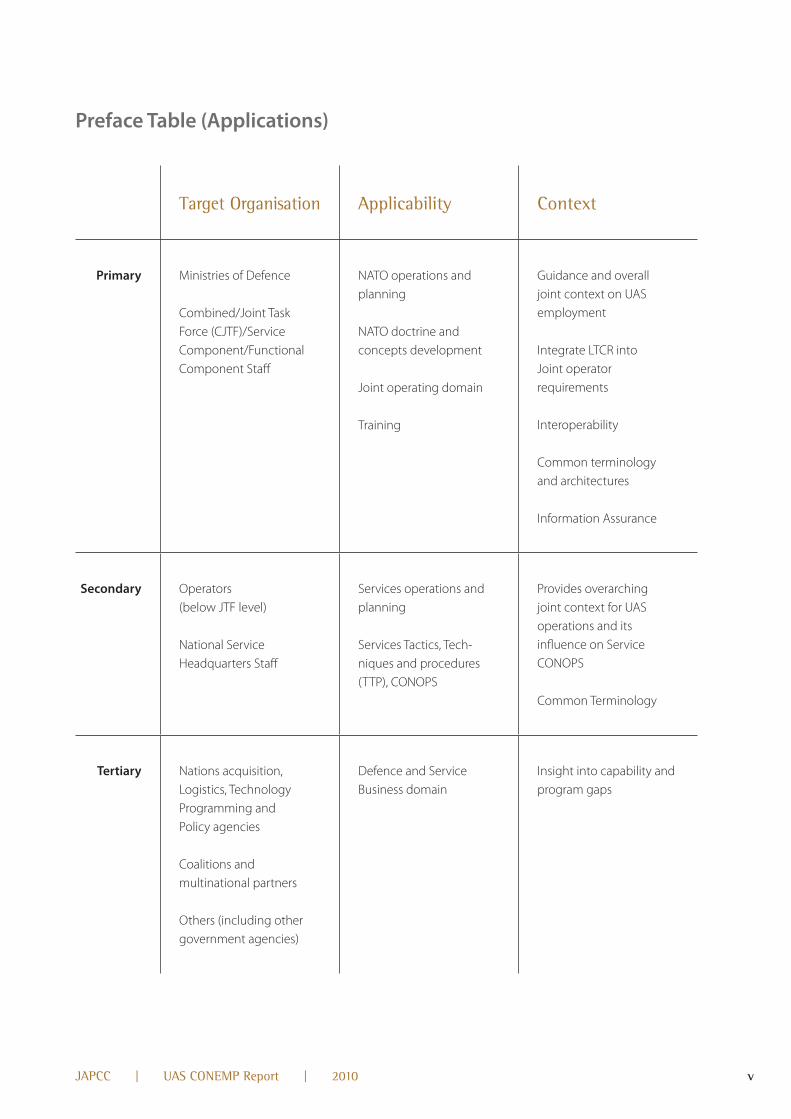
Preface Table (Applications)
Target organisation Applicability Context
Primary Ministries of Defence
Combined/Joint Task Force (CJTF)/Service Component/Functional Component Staff
naTO operations and planning
naTO doctrine and concepts development
Joint operating domain
Training
Guidance and overall joint context on uaS employment
Integrate LTCr into Joint operator requirements
Interoperability
Common terminology and architectures
Information assurance
Secondary Operators (below JTF level)
national Service Headquarters Staff
Services operations and planning
Services Tactics, Tech-niques and procedures (TTP), COnOPS
Provides overarching joint context for uaS operations and its influence on Service COnOPS
Common Terminology
Tertiary nations acquisition, Logistics, Technology Programming and Policy agencies
Coalitions and multinational partners
Others (including other government agencies)
Defence and Service Business domain
Insight into capability and program gaps
10106004f_UASConempReport.indd 5 15.03.2010 00:06:56

vi JAPCC | UAS ConemP Report | 2010
Overview
This publication provides the naTO vision for the opera-
tion, integration, and interoperability of uaS until 2025.
This document describes a capabilities-based approach
to uaS employment, which enhances the joint opera-
tor’s ability to execute assigned missions and tasks. It
emphasizes joint guidance for optimum uaS employ-
ment across a range of military operations. The docu-
ment focuses at the operational (campaign) level of war-
fare and Civil Support (CS) for use by naTO and its
multi- national/coalition partners. additionally, this docu -
ment assists with the development of joint/coalition,
Service doctrine, COnOPS, and operational plans.
Chapter I - Introduction: Sets the stage for a uaS
capability discussion by briefly describing the back-
ground and the necessity for tasking which resulted in
this document development. This chapter also briefly
describes and differentiates uaS from manned aircraft.
Chapter II - UAS Family of Systems: Defines and
describes key uaS terms and related employment
concepts. It begins with a discussion of uaS compo-
nents (aircraft, payload, communications, control,
support, and the human aspect). next it defines naTO
uaS categories. Finally, it provides an overview of uaS
capabilities and limitations by category.
Chapter III - Planning and Employment Consid-erations: Highlights the most important issues
regarding uaS employment in the near term.
Optimal uaS employment presents complex and
unique challenges requiring joint planners to be
educated with the information needed to mitigate
those challenges.
Chapter IV - UAS Support to Joint or Coalition Force Operations: Provides a top-level discussion for
the optimised employment of uaS based on current
doctrine and near- to mid-term concepts. This chapter
also highlights the range of potential operational
missions in which uaS can be employed in support of
the joint force or its component commanders.
Chapter V - Doctrine, Organisation, Training, Materiel, Leadership and Education, Personnel, Facilities, and Interoperability (DOTMLPFI) Con-siderations: Highlights uaS issues that may require
DOTMLPFI changes or new materiel solutions. The
chapter provides issues, discussions, recommenda-
tions, and ongoing efforts that are addressing the issues.
Appendix A - Operational Vignettes: Puts the
discussion of Chapter IV into context by including
vignettes to illustrate how uaS are employed in sup-
port of joint/coalition operations. The vignettes include
a major operation and campaign, a non-combatant
evacuation operation (nEO), urban, Homeland De-
fence (HD), and Civil Support operations.
10106004f_UASConempReport.indd 6 15.03.2010 00:06:57

1JAPCC | UAS ConemP Report | 2010
CHaPTER I Introduction 1.1 Background
uaS are considered to be the system, whose compo-
nents comprise the necessary equipment, network,
and personnel to control an unmanned aircraft (ua).
1.1.1 uaS are recognized as critical assets across all
levels of joint/coalition command. Demand for the ca-
pabilities uaS can provide are likely to grow in con-
flicts. Due to this increased demand, resolving em-
ployment and system integration challenges is more
important than ever.
1.1.2 uaS are just one part of a complex blending of
manned and unmanned aerial systems across Services
and across nations. This concept of employment will
focus on several scenarios where uaS can reduce risk,
increase confidence and enable mission success. The
growing number of uaS potential mission sets and
scenarios demand their comprehensive integration
into present and future combined and joint opera-
tions. It is essential to seamlessly integrate uaS with
manned operations in a joint environment. There is a
pressing need to integrate and fuse the C4ISr data
from uaS with that gathered from existing and future
C4ISr architectures to bring about proper integration
with the Intelligence cycle.
1.2 Aim
This document provides a common approach to the
development of the capabilities of current and future
uaS for operational planning and execution under a
wide range of conditions. It will allow joint operators
and planners to select from the uaS capabilities set to
achieve the desired operational effects and will:
1.2.1 Provide a naTO vision and joint/coalition con-
text for the operation, integration, and interoperability
of uaS in campaigns through the year 2025.
1.2.2 Describe a capabilities based approach to uaS
employment, which enhances the joint operator’s
ability to execute assigned missions and tasks across
the entire range of military operations.
1.2.3 Establish naTO joint guidance for uaS planning
and execution at the operational (campaign) level of
military operations.
1.3 Scope
The scope of this document deals specifically with
uaS and their contribution to joint operational scena-
rios. naTO‘s strategic context and future environment
is mainly taken from the work of the Multiple Future
Project (MFP) and the Defence requirements review
(Drr) process. It uses the MFP implications for future
military engagement within a comprehensive ap-
proach to address complex, dynamic problems. The
Drr process defines several operational scenarios.
The timeframe considers employment principles for
current and future operations as defined by naTO’s
long term capabilities requirements. This document
reflects these operational considerations and employ-
ment scenarios.
1.4 Implications
The implications of uaS employment principles span
several areas for future work. uaS employment must
be integrated into operational design across the full
range of military operations. uaS must be considered
in the development or modification of operating
concepts, doctrine, STanaGs, and tactics, techniques
and procedures. It may also assist the integration of
uaS into naTO education, training, exercises, and
evaluation. These uaS employment principles also
support technology development and procurement
and are linked to capability developmental elements
known as DOTMLPFI . as a baseline for the uaS con-
tribution to the Joint operation (along with future
doctrine de ve lopment) and new Standard Operating
Procedures (SOPs), these principles support com-
manders by enabling the integrated and efficient use
of uaS capabilities.
10106004f_UASConempReport.indd 1 15.03.2010 00:06:57

2 JAPCC | UAS ConemP Report | 2010
1.5 What makes UAS Different
uaS operations resemble those of manned aircraft in
many ways. The similarities include: aerial platforms; dis-
ciplined, professional operators/crews; use of airspace;
requirement for aviation maintenance/logistical support;
and training. However, the major difference of uaS over
manned aircraft is the ability to operate in dangerous
environments without the risk to human life, together
with increased loiter time over the operating area. Con-
versely, there are challenges associated with removing
the human from the airframe, most notably the necessity
for data links for flight control and aircraft monitoring.
This document highlights the specific capabilities and
limitations the joint operator must be aware of when
planning, allocating, integrating, and controlling uaS.
1.5.1 reduced risk. The proliferation of uaS across naTO
provides an enabling capability to the comman der to
minimize risk across the spectrum of conflict within an
established Joint Operational area (JOa). Some specified
and implied joint tasks which may be too “dull, dirty or
dangerous” for direct human involvement may require
unmanned systems to enable the successful accom-
plishment of the task while lowering the risk to per-
sonnel and equipment. The commander’s willingness to
risk an asset will usually be greater when no risk to
human life is involved. uaS can lower the risk and raise
the political acceptance and confidence that high risk
missions will be successful. Even in missions that have
traditionally been performed by manned aircraft, uaS
can improve joint effectiveness and reduce uncertain-
ties by closing the seams between the elements of the
Find, Fix, Track, Target, Engage, assess (F2T2Ea) cycle. The
commander now has an expanded risk envelope in
which combat operations can be conducted. The fol-
lowing are two examples of high risk operations where
uaS is used to reduce mission risk:
1.5.1.1 ua can carry a chemical, biological, radiologi-
cal, and nuclear (CBrn) sensor into areas unsafe for
manned aircraft, allowing detection of such threats
without risking human operators.
1.5.1.2 In recent combat operations, during high pri-
ority missions, commanders have assumed the risk for
potential loss of ua in circumstances that would not
normally be permissible for manned aircraft (e.g.,
adverse weather conditions, maintenance anomalies,
or low fuel states).
1.5.2 Design. Without the requirements associated with
manned flight, ua can be designed to any required size
appropriate to the mission from tactical to strategic.
1.5.3 Mission Flexibility. although possible with
manned aircraft, uaS are routinely employed in multi-
tasked roles in a single sortie. Certain missions may
not be planned before the aircraft launches, but the
flexibility inherent to uaS allows the commander to
re-task the aircraft multiple times on a single sortie.
This gives the JFC operational capabilities where and
when needed and enhances the operational art of
time-space-force considerations.
1.5.4 Endurance and Persistence. Two related terms
where endurance refers to the ability for increased
time on station and persistence refers to the tenacity
of purpose and efficacy of uaS capabilities. For exam-
ple, a ua can be designed to maximize endurance,
which may translate into increased effective mission
time. Depending on payload configurations, some
uaS routinely exceed 20 hours of effective mission
time and future capabilities may exceed months of
operational endurance. Other types of ua can be
launched within minutes, remain aloft for a few
minutes to produce an effect (ISr, Decoy, etc.), land
and be re-tasked for another launch as needed as
needed to provide persistence over the battlefield.
1.5.4.1 Separating the human from the ua introduces
challenges with airspace integration both in a military
role, as well as air traffic control procedures in non-
segregated airspace:
1.5.5 airspace Deconfliction/Integration. The ua ope-
rator has limited visual and situational awareness cues.
To avoid mid-air collisions, the current methodology
employed by manned aviation includes procedural
deconfliction, visual acquisition, and terminal control
avoidance systems. While uaS may communicate with
air traffic control and/or use onboard avoidance systems,
10106004f_UASConempReport.indd 2 15.03.2010 00:06:57

3JAPCC | UAS ConemP Report | 2010
ua operators typically do not have the same visual field
of view and response times as manned aircraft. To over-
come these limitations, ua operators must build and
maintain their situational awareness through utilization
of other resources (e.g., observers, ground radar, electro-
optical/infrared (EO/Ir) cameras, chat, etc.). Today’s
environment uses segregated air space as the means of
ensuring safe operation between manned and un-
manned aviation. The ultimate goal is for full integration
of uaS with manned aviation in all areas of operation.
1.5.6 Standards and Training. uaS operations require
standardized rules, regulations and procedures. naTO
currently lacks many of these standards which may
reduce overall interoperability and integration. STanaG
4670 defines minimum uaS operator training standards.
1.5.7 Data Links. uaS are constrained by data links,
whether conducting line-of-sight (LOS) or beyond line-
of-sight (BLOS) operations. Interruption or loss of the
controlling data link could result in degraded mission
effectiveness, mission failure, and in extreme cases, loss
of the ua. LOS operating distances are affected by uaS
equipment, terrain, and atmospheric conditions. BLOS
operations are sensitive to any anomalies in a complex
communications relay structure. The number of uaS
that can be employed in a common operating area may
be constrained by the available satellite bandwidth. Po-
tential uaS data link vulnerabilities may be mitigated by
encryption, the creation of redundant critical nodes,
and further advances in autonomy/automation.
CHaPTER II UAS Family of Systems
2.1 UAS Components
From an operational perspective, uaS consist of sev-
eral common components. Various documents and
studies have separated uaS into different compo-
nents. The uaS components are: the unmanned air-
craft, payloads, human element, control elements,
data links and support element. The following sec-
tions describe these components. Since these com-
ponents must be integrated into a whole uaS, it could
be argued that what is included in one element could
be of more value included in another (e.g., communi-
cation and payloads). Direction, collection, process-
ing, and dissemination, while not technically part of
the uaS, are critical to integrate and optimize the
capabilities of uaS with the operation.
2.1.1 unmanned aircraft (ua). an aircraft that does not
carry a human operator and is capable of flight under
remote control or autonomous programming. a ua is de-
signed to be recoverable, but can be expendable and can
carry a lethal or non-lethal payload. ua are rotary or fixed-
wing aircraft or lighter-than-air vehicles, capable of flight
without an onboard crew. For the purposes of this docu-
ment, all ua are intended to be recovered (i.e., landed),
Figure 1: Unmanned Aircraft System Components
PayloadSystemUser
UnmannedAircraft
HumanElement
ControlElementsData Links
SupportElement
UnmannedAircraftSystems
C4ISR
10106004f_UASConempReport.indd 3 15.03.2010 00:06:58

4 JAPCC | UAS ConemP Report | 2010
even though they may be expended. ua may be oper-
ated remotely or autonomously. The ua includes the
aircraft and integrated equipment (propulsion, avionics,
fuel, navigation, and communication systems).
2.1.2 Payload. ua payloads include sensors, commu-
nications relay, weapons, and cargo. Payloads may be
internally or externally carried. Modular sensor inter-
faces should conform to naTO interface standards
(STanaG 4586).
2.1.2.1 Sensors. The majority of today’s payloads are
imaging sensors, such as electro-optical (EO), infrared (Ir),
and radar (synthetic aperture radar [Sar], inverse synthet-
ic aperture radar [ISar], and maritime search radar). In
addition, there are ground, surface and maritime moving
target indicators, light detection and ranging (LIDar),
chemical, biological, radiological, nuclear, or high yield
explosive (CBrnE) detection, automated identification
system (aIS), measurement and signature intelligence,
and signals intelligence (SIGInT) sensors. Sensor packages
may also include a laser range finder and/or laser
designator (LrF/D) capability. These pulse laser systems
enable accurate and instantaneous distance and speed
measurement for target location and the ability to pro-
vide target designation for laser guided weapons. Future
technological advancements may include sensor types,
such as environmental, multispectral, and hyper spectral.
2.1.2.1.1 Sensors downlinks include full motion video
(FMV) and still frame imagery. FMV transmissions typi-
cally consume large amounts of bandwidth, while still
frame imagery transmissions may consume less band-
width. Some current narrow field of view sensors may be
replaced by wide area sensors with the ability to cross
cue to multiple points of interest for multiple users. Some
uaS have sensors capable of topographical mapping
and measure the geometric quantities of an object.
2.1.2.2 Communications relay. Communications relay
payloads provide the capability to extend voice and data
transmissions via the ua. For example, these payloads
presently provide relay capabilities for Single Channel
Ground and airborne radio System, Enhanced Position
Location reporting System radios, remote sensors, and
data networks. For operations involving allied/coalition
forces, interoperability will be the primary factor for
successful communications and information sharing.
Future communications gateway payloads may include
bridging, range extension, and translation capabilities
that will allow users to communicate between disparate
types of radios, data links, and networks.
2.1.2.3 Weapons. ua may employ both lethal and non-
lethal weapons in order to achieve the desired effect.
2.1.2.3.1 Lethal Effects: Current weapons employed
by unmanned aircraft are in the 500-pound class or
less and are usually Global Positioning System (GPS) or
laser-guided.
2.1.2.3.2 non-lethal Effects: Some non-lethal capa-
bilities being considered for uaS employment include:
electrical, directed energy, acoustics, chemical, kinetic
energy, barriers and entanglements.
2.1.2.4 Cargo. Some uaS have the capability to utilize
non-expendable payloads for delivery and/or pickup
of supplies and equipment. One example is delivery
of medical supplies to SOF units behind enemy lines,
or, perhaps in the future to transport the wounded as
well as personnel to various locations.
2.1.3 Human Element. This aspect of the uaS is typically
not considered a separate element, but it is perhaps the
most critical to successful uaS employment. The idea that
uaS are “unmanned” is a misnomer. While the aircraft itself
is not manned, the system is manned. uaS require a
certain amount of human involvement to prepare and
execute the mission. For most uaS, primary personnel
tasks include, but are not limited to, the operator (aircraft
and/or payload), maintainer, mission commander, and
intelligence analyst (for some uaS, intelligence analysts
are not considered as part of the system). uaS personnel
must be qualified in their particular area of involvement,
and they must maintain currency in their particular aspect
of operations. Commanders should take into account uaS
operator fatigue and ensure units are sufficiently manned
to accomplish missions without interruption.
2.1.4 Control Element. The control element, whether
ground-based, sea-based, or airborne, handles multiple
10106004f_UASConempReport.indd 4 15.03.2010 00:06:58
5JAPCC | UAS ConemP Report | 2010
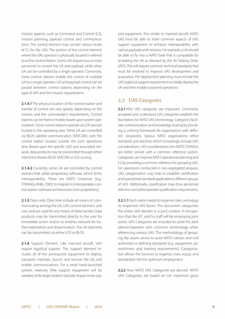
mission aspects, such as Command and Control (C2),
mission planning, payload control, and communica-
tions. The control element may contain various levels
of C2 for the uaS. The portion of the control element
where the uaS operator is physically located is referred
to as the control station. Some uaS require two or more
personnel to control the ua and payload, while other
ua can be controlled by a single operator. Conversely,
some control stations enable the control of multiple
ua by a single operator. ua and payload control can be
passed between control stations depending on the
type of uaS and the mission requirements.
2.1.4.1 The physical location of the control station and
transfer of control can vary greatly, depending on the
mission and the commander’s requirements. Control
stations can be fixed or mobile, based upon system opti-
mization. Some control stations operate via LOS and are
located in the operating area. Other ua are controlled
via BLOS satellite communication (SaTCOM), with the
control station located outside the joint operations
area. Based upon the specific uaS and associated net-
work, data products may be transmitted through either
inter/intra-theatre BLOS SaTCOM or LOS routing.
2.1.4.2 Currently, some ua are controlled by control
stations that utilize proprietary software, which limits
interoperability. There are naTO initiatives (e.g.,
STanaGs 4586, 7085) to migrate to interoperable con-
trol station software architectures (non-proprietary).
2.1.5 Data Links. Data links include all means of com-
municating among the ua, uaS control element, and
user, and are used for any means of data transfer. Data
products may be transmitted directly to the user for
immediate action and/or to another network for fur-
ther exploitation and dissemination. The ua data links
can be transmitted via either LOS or BLOS.
2.1.6 Support Element. Like manned aircraft, uaS
require logistical support. This support element in-
cludes all of the prerequisite equipment to deploy,
transport, maintain, launch, and recover the ua, and
enable communications. For a small hand-launched
system, relatively little support equipment will be
needed, while larger systems typically require more sup-
port equipment. also similar to manned aircraft, naTO
uaS must be able to share common aspects of uaS
support equipment to enhance interoperability with
various payloads and missions. For example, a ua should
be able to fly into a naTO base that is compatible for
re-tasking the ua as directed by the air Tasking Order
(aTO). This will require common technical standards that
must be resolved to improve uaS development and
acquisition. Pre-deployment planning must include the
uaS logistical support requirement to initially deploy the
ua and then enable sustained operations.
2.2 UAS Categories
2.2.1 Why uaS categories are important. Commonly
accepted and understood uaS categories establish the
foundation for naTO uaS terminology. Categories facili-
tate communication and knowledge sharing by provid-
ing a unifying framework for organisations with differ-
ent viewpoints. Various naTO organisations refine
standards and doctrine which increasingly include uaS
considerations. uaS considerations into naTO STanaGs
are better served with a common reference system.
Categories can improve naTO operational planning and
C2 by providing a common reference for grouping uaS.
For operations conducted in non-segregated airspace,
uaS categorization may help to establish certification
and operational standards applicable to different groups
of uaS. additionally, classification may drive personnel
selection and pilot/operator qualification requirements.
2.2.1.1 Each nation needs to organise, train, and equip
its respective uaS forces. This document categorizes
the entire uaS domain in a joint context. In recogni-
tion that the JFC and his staff will be employing joint
assets, uaS Categories are included to assist the joint
planner/operator with common terminology when
referencing various uaS. The methodology of group-
ing like assets serves to assist naTO nations and civil
authorities in defining standards (e.g., equipment, air-
worthiness and training requirements). Categoriza-
tion allows the Services to organise, train, equip, and
standardize uaS for optimum employment.
2.2.2 How naTO uaS Categories are derived. naTO
uaS Categories are based on ua maximum gross
10106004f_UASConempReport.indd 5 15.03.2010 00:06:58
6 JAPCC | UAS ConemP Report | 2010
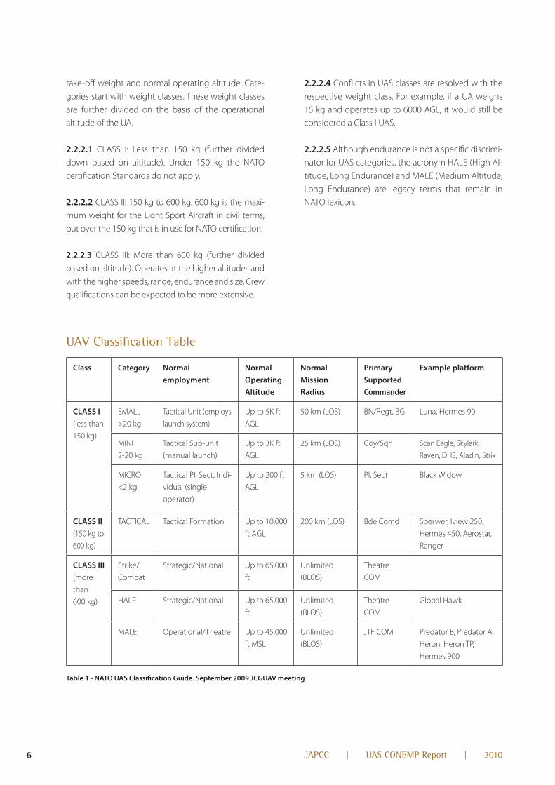
take-off weight and normal operating altitude. Cate-
gories start with weight classes. These weight classes
are further divided on the basis of the operational
altitude of the ua.
2.2.2.1 CLaSS I: Less than 150 kg (further divided
down based on altitude). under 150 kg the naTO
certi fication Standards do not apply.
2.2.2.2 CLaSS II: 150 kg to 600 kg. 600 kg is the maxi-
mum weight for the Light Sport aircraft in civil terms,
but over the 150 kg that is in use for naTO certification.
2.2.2.3 CLaSS III: More than 600 kg (further divided
based on altitude). Operates at the higher altitudes and
with the higher speeds, range, endurance and size. Crew
qualifications can be expected to be more extensive.
2.2.2.4 Conflicts in uaS classes are resolved with the
respective weight class. For example, if a ua weighs
15 kg and operates up to 6000 aGL, it would still be
considered a Class I uaS.
2.2.2.5 although endurance is not a specific discrimi-
nator for uaS categories, the acronym HaLE (High al-
titude, Long Endurance) and MaLE (Medium altitude,
Long Endurance) are legacy terms that remain in
naTO lexicon.
UAV Classification Table
Class Category Normal employment
Normal Operating Altitude
Normal Mission Radius
Primary Supported Commander
Example platform
CLASS I (less than
150 kg)
SMaLL
>20 kg
Tactical unit (employs
launch system)
up to 5K ft
aGL
50 km (LOS) Bn/regt, BG Luna, Hermes 90
MInI
2-20 kg
Tactical Sub-unit
(manual launch)
up to 3K ft
aGL
25 km (LOS) Coy/Sqn Scan Eagle, Skylark,
raven, DH3, aladin, Strix
MICrO
<2 kg
Tactical PI, Sect, Indi-
vidual (single
operator)
up to 200 ft
aGL
5 km (LOS) PI, Sect Black Widow
CLASS II (150 kg to
600 kg)
TaCTICaL Tactical Formation up to 10,000
ft aGL
200 km (LOS) Bde Comd Sperwer, Iview 250,
Hermes 450, aerostar,
ranger
CLASS III (more
than
600 kg)
Strike/
Combat
Strategic/national up to 65,000
ft
unlimited
(BLOS)
Theatre
COM
HaLE Strategic/national up to 65,000
ft
unlimited
(BLOS)
Theatre
COM
Global Hawk
MaLE Operational/Theatre up to 45,000
ft MSL
unlimited
(BLOS)
JTF COM Predator B, Predator a,
Heron, Heron TP,
Hermes 900
Table 1 - NATO UAS Classification Guide. September 2009 JCGUAV meeting
10106004f_UASConempReport.indd 6 15.03.2010 00:06:58
7JAPCC | UAS ConemP Report | 2010
2.3 UAS Capabilities and Limitations
2.3.1 General. unique design features of uaS that
enable a desired capability (e.g., long endurance,
hand-launched) may also impose some limitations
on performance.
2.3.2 Capabilities. uaS provide the commander with
an effective lethal or non – lethal means for achieving
his objectives across the full spectrum of operations.
uaS capabilities may improve situational awareness in
areas such as ISr, and reconnaissance, surveillance,
and target acquisition (rSTa); laser designation; attack;
damage assessment; CBrnE detection and monitor-
ing; cargo delivery and logistics resupply and commu-
nications gateway extension (e.g., communications
relay, network extension); combat search and rescue.
They may also assist in psychological operations (PSyOP);
combat identification; early warning; locating and
monitoring enemy military equipment; monitoring
borders for smuggling; detecting mines (land and sea)
and Improvised Explosive Devices (IED); infrastructure
reconstitution; geospatial intelligence and SIGInT
support; maritime vessel identification; meteorologi-
cal and oceanographic condition (METOC) monitor-
ing support; personnel recovery (Pr); and support to
law enforcement.
2.3.3 Limitations. uaS share many of the limitations of
manned aircraft. The limitations that most frequently
affect uaS are reliance on data links and adverse
atmospheric conditions such as wind, turbulence, and
icing conditions.
2.3.3.1 Data Link. Currently, the most significant limita-
tion associated with uaS involves the unique require-
ment of uaS to be controlled through a data link.
although most uaS can fly pre-programmed auto -
nomous missions, they still require some form of data
link for aircraft systems/mission monitoring and manu-
al flight control. Data link limitations include: vulnera-
bility to electromagnetic interference (EMI), physical
distance and power strength of the signal, physical
obstructions to the signal (e.g., lost link), bandwidth
availability, and frequency allocation and deconfliction
in saturated environments.
2.3.3.2 Winds. ua have crosswind limitations that may
affect launch and recovery operations. The relatively
slow airspeeds of many ua also make them susceptible
to winds at altitude, which may influence the ua’s
effective mission time and increase fuel requirements.
If winds at operating altitude are forecast to be greater
than the ua’s maximum sustainable airspeed, the ua
may not be able to reach, remain on, or return from
station. Winds in the target area may also influence
target acquisition and weapons employment. Targets
may be obscured by blowing smoke, sand, or dust.
2.3.3.3 Turbulence. Turbulence makes ua more diffi-
cult to control during all phases of flight and impact
ua ability to maintain data links for mission execution.
Turbulence may also affect stability of the sensor and
potentially prevent weapons employment. In some
cases, turbulence may cause the flight control servos
to overheat or fail rendering the flight controls inop-
erative. If the turbulence exceeds the structural capa-
bility of the ua, structural failure may occur.
2.3.3.4 Icing. Most ua do not have anti-icing capa-
bilities and cannot fly in freezing precipitation or icing
conditions. This includes climbing or descending
through icing in an attempt to reach non-icing
conditions.
2.3.3.5 Miscellaneous Considerations. Launch and
recovery method, acoustic footprint, day/night (e.g.,
some ua may not have Ir sensors), airspace avail-
ability, special fuels, batteries, space weather effects
(e.g., solar winds) on data link, data storage, fog, smoke,
heavy precipitation, low cloud decks, thermal cross-
over, excessive heat, high altitudes (small uaS), high
humidity and sea state (maritime uaS).
2.4 Capabilities / Limitations by Class
2.4.1 Class I.
2.4.1.1 Capabilities. Class I uaS are typically hand-
launched, self contained, portable systems employed
at the small unit level or for base security. They are
capable of providing “over the hill” or “around the cor-
ner” type reconnaissance and surveillance. Payloads
10106004f_UASConempReport.indd 7 15.03.2010 00:06:59

8 JAPCC | UAS ConemP Report | 2010
are generally fixed EO/Ir, and they have a negligible
logistics footprint.
2.4.1.2 Limitations. Class I ua typically operate within
the operator’s line of sight at low altitudes, generally
less than 5,000 feet aGL and have a limited range/en-
durance.
2.4.2 Class II.
2.4.2.1 Capabilities. Class II ua are typically medium-
sized, often catapult-launched, mobile systems that
usually support brigade and below ISr/rSTa require-
ments. These systems operate at altitudes less than
10,000 feet aGL with a medium range. They usually
operate from unimproved areas and do not usually
require an improved runway. Payloads may include a
sensor ball with EO/Ir and an LrF/D capability. Class II
ua are typically employed within tactical formations
and usually have a small logistics footprint.
2.4.2.2 Limitations. Class II ua usually have less range/
endurance, and less payload capability than Class III
ua. They require a high degree of coordination / inte-
gration in combat and civilian air space.
2.4.3 Class III.
2.4.3.1 Capabilities. Class III ua are typically the largest
systems, operate in the high altitude environment,
and typically have the greatest range/endurance and
airspeed. They perform specialized missions including
broad area surveillance and penetrating attacks. Pay-
loads may include sensor ball with EO/Ir, radars, lasers,
Sar, communications relay, SIGInT, aIS, and weapons.
2.4.3.2 Limitations. Most Class III ua require improved
areas for launch and recovery. The logistics footprint
may approach that of manned aircraft of similar size.
They typically have the most stringent airspace
re quire ments. Lack of SaTCOM would prevent use
when being operated BLOS. These ua typically have
decreased endurance when carrying weapons due
to decreased fuel load capability and aerodynamic
effects associated with external hard points.
CHaPTER III Employment Considerations
3.1 General
Many of the issues that need to be considered when
employing uaS are the same or very similar to those
of manned assets. However, there are some significant
differences that determine how uaS should be em-
ployed. Whilst this document recognizes that nations
may employ uaS based on service–specific concepts,
this chapter aims to provide a standard framework for
uaS employment across the alliance.
3.2 C2 of UAS
The JFC should be given the authority to determine
the use and control of all uaS forces under his com-
mand. The functional component commanders will
maintain C2 of their assigned or attached uaS unless
the JFC transfers operational control (OPCOn) or tacti-
cal control (TaCOn) to another component. The fol-
lowing should be considered;
3.2.1 unique aspects of uaS C2. C2 processes for uaS
are similar to those for manned assets, but several
aspects of uaS can make C2 particularly challenging.
First, the physical separation of the ua from the opera-
tor requires robust C2 data links. Second, most uaS
can be flown both manually and/or in a pre-pro-
grammed mode. In the pre-programmed mode, uaS
still require some form of data link with the aircraft to
allow an operator to monitor aircraft/systems status
and switch to manual flight control. Third, uaS may be
capable of transferring control of the aircraft and/or
payloads to multiple operators while airborne.
3.2.2 C2 of uaS in Joint Operations. Two critical C2
functions in joint air operations are allocation and task-
ing of resources. Those uaS allocated by the JFC to the
air component commander will comply with the task-
ing process described in aJP 3.0. Transfer of uaS C2
within a Service or functional component is handled
through Service or functional command structures.
10106004f_UASConempReport.indd 8 15.03.2010 00:06:59

9JAPCC | UAS ConemP Report | 2010
3.2.3 C2 of Theatre-Capable uaS. Like manned aircraft,
theatre-capable uaS may be used to support the JFC,
component commanders operations, or in support of
other component commanders. as these scarce assets
can be in high demand, careful consideration must be
made by the JFC, when making apportionment and
allocation decisions. The requirements of the compo-
nent commanders should be balanced against the
overall Joint Force requirements. How theatre-capable
uaS operations are managed and planned will vary
based on the type and phase of an operation.
3.2.3.1 Theatre-capable uaS are typically used for
three types of missions: (1) ISr/rSTa, (2) tactical C2,
and (3) Joint Fires. ISr/rSTa, in this context, describes
the process of building activity patterns through
repeated visits to a large set of targets. This data may
require further exploitation to develop actionable
intelligence. The ISr/rSTa planning process aims to
maximize the number of collection targets for each
sortie. Tactical C2 involves the collection of real-time,
actionable, and often perishable data in direct sup-
port of a ground commander. Tactical C2 may involve
many hours of tracking a single target, following
vehicles, or examining planned routes. Support to
Joint Fires involves the development of targeting
data and may include the use of laser designation, or
actual employment of a weapon. Support to Joint
Fires may occur in the course of another mission or
may be pre-planned. Current joint doctrine provides
for parallel planning processes for ISr/rSTa and Joint
Fires. These parallel processes have been sufficient
for manned aircraft, but theatre-capable uaS, with
long dwell times and multi-mission capability, inclu-
ding multiple missions on the same sortie, require
significantly more coordination between the two
processes. The requirement to provide support to C2
further stresses and complicates the use of theatre-
capable uaS.
3.2.4 Factors to Consider When Tasking uaS. Planners
and operators should request a desired condition or
effect and not a specific ua to support a mission. For
example, many different uaS can provide imagery,
so depending on the desired effect, there may be
more than one type of uaS to support the mission.
re-tasking a uaS during mission execution must be
carefully considered; dynamic re-tasking of uaS
should be determined by the appropriate comman-
der (e.g., with OPCOn or TaCOn) after evaluating
the full impact of diverting the capability from the
current mission.
3.2.4.1 Transfer of Control during Mission Execution.
If a uaS is re-allocated to support another command-
er’s objective, the supported commander should, to
the maximum extent feasible, use the established
C2 arrangements. Following uaS transfer of control,
intelli gence collection managers and ISr operations
managers may adjust plans and reprioritize available
ISr assets and capabilities.
3.2.4.2 C2 of uaS in Time-sensitive Targeting (TST).
uaS can be effective in support of TST missions.
Commanders should determine whether they are
responsible for an TST and be aware that they may
be required to act as a supporting commander for
the TST mission. TST situations may require uaS to
support close air support (CaS), strike coordination
and reconnaissance, air interdiction (aI), other joint
fires missions, and personnel recovery (Pr). Specific
tasks for the uaS may include: target acquisition/
marking, terminal guidance of ordnance, providing
precision coordinates for GPS aided munitions, de-
livery of onboard precision-guided ordnance, battle
damage assessment (BDa), and retargeting (i.e.,
shoot-look-shoot). In the TST role, uaS are routed,
controlled, and deconflicted in the same manner as
fixed- and rotary-winged manned aircraft, as out-
lined in joint doctrine.
3.2.5 Future Direction of uaS C2. a networked archi-
tecture is the most likely solution for future joint C2
of uaS. authorized users may be able to direct uaS
missions in their areas of operation. The migration
from current point-to-point data links to networked
data links enables more users to have access to ua
payload and telemetry data. Gateway nodes may dis-
tribute higher bandwidth data streams to selected
users and provide lower bandwidth streams directly
to the warfighter.
10106004f_UASConempReport.indd 9 15.03.2010 00:06:59

10 JAPCC | UAS ConemP Report | 2010
3.2.5.1 Some ground control stations (GCS) are capa-
ble of controlling multiple ua from a single location.
Future network architectures will enable authenticated
users to control multiple ua, and/or access products
being distributed by multiple ua.
3.2.5.2 advances in onboard computational and
stor age capacity may allow for higher levels of ua
autonomy/automation. ua autonomous/automated/
pre-programmed operations will present C2 and
other challenges that must be addressed as the tech-
nology matures.
3.2.5.3 as data dissemination capability expands
requests for support will increase. This may require
support tools to be developed to collect, filter, and
prioritize such requests.
3.3 employment Considerations by UAS Categories
3.3.1 Class I. By virtue of size, Class I uaS are normally
man-portable, hand-launched and operated by an
individual controller, and normally have a range of less
than 20 miles. They may be tracked using a force track-
ing system and typically have an endurance of up to
two hours. Simplicity of launch and recovery allows a
unit to employ Class I uaS assets quickly, within the
constraints of airspace coordination measures.
3.3.2 Class II. By virtue of size, Class II uaS are limited
in range and their ability to support large areas of
operation. They are typically theatre based, require
pre-surveyed launch and recovery areas, and may be
tracked using force tracking systems. Simplicity of
launch and recovery operations allows a unit to em-
ploy Class II uaS assets quickly, within the constraints
of airspace coordination measures.
3.3.3 Class III. Most Class III fixed wing uaS require run-
ways for launch and recovery, although some are cata-
pult launch assisted. Mission focus dictates a forward
or remote split operations (rSO) footprint (e.g., phase
of the operations, major combat operations (MCO)
versus Irregular Warfare (IW)/Counter Insurgency (COIn),
supported commander etc.). Class III uaS are the most
complex and provide the most capability. They will re-
quire more airspace considerations than other classes,
leading to airspace management requirements on
par with manned aircraft. Depending on weight,
power, and size restrictions, this class can be tracked
by either a force tracking system or a transponder.
3.4 mission Planning Considerations
Current doctrinal planning considerations for manned
aircraft are applicable to ua, with modification.
3.4.1 Flight Planning. Every ua flight requires some
degree of flight planning, regardless of the size of the
aircraft, the mission profile, or the flight location. Differ-
ent phases of the mission may be executed by differ-
ent personnel/crewmembers (e.g., takeoff/landing crews
and mission crews). Planners must ensure the mission
briefs, goals, tasks, etc., are coordinated among all per-
tinent crew to ensure mission understanding and suc-
cess. The unique requirements of ua data links re-
quires detailed planning for lost link and/or emer gency
recoveries. Larger Class II and Class III ua increasingly
operate outside military controlled airspace. Planners
must plan the route, determine communication, navi-
gation, and surveillance requirements, verify weather,
weight and balance, and file a flight plan with the
controlling agency in order to obtain a flight clear-
ance. For take off and landing of Class III ua they
should consider the implications of integration with
manned aircraft, if present. uaS operating in inter-
national airspace must comply with international
laws, customs, and practices, and other multinational
and bilateral agreements. Smaller Class II and Class I
ua may have fewer planning requirements, but should
still consider all these factors.
3.4.2 airspace Coordination Order (aCO). uaS air-
space coordination must be included in the aCO
development process.
3.4.3 airspace Management. uaS operate in both
national and international airspace as well as under
military and civilian air traffic control. airspace man-
agement remains one of the top factors impacting
10106004f_UASConempReport.indd 10 15.03.2010 00:06:59

11JAPCC | UAS ConemP Report | 2010
uaS integration with other airspace users. For the
purposes of this document, airspace is divided be-
tween military airspace and civilian airspace. Military
airspace is that airspace controlled by the military with-
out the requirement for airspace users to coordinate
with a civilian airspace control authority or adherence
to civilian airspace policies or regulations. Civilian air-
space is that airspace governed under normal peace-
time policies and regulations. The joint operator must
understand how airspace control measures apply to
their systems.
3.4.4 Military airspace. The airspace Control authority
(aCa), typically the JFaCC, is responsible for airspace
management and should be aware of integration
issues for all uaS. ua that fly above the coordinating
altitude are required to appear in the aTO, and air-
space management is accomplished using the same
positive or procedural control measures in place for
manned systems. Joint operators should be familiar
with where their systems operate, procedural controls
(such as identification manoeuvres), contingencies for
loss of ua control, and clearance of fires procedures.
3.4.4.1 In this case, uaS operators will conduct opera-
tions, in accordance with JFaCC guidance, normally
found in the theatre airspace control plan. Transponder
equipped uaS can be identified by radar with interro-
gator capability. If the uaS has no transponder or space
coordinating measures are required to deconflict the
uaS from other airspace users. Class I and II ua provide
a challenge for identification because they currently
do not carry transponders because of weight and
power limitations, but can be tracked using off-board
command and control systems (e.g., Force Tracking
System, Tactical airspace Integration System).
3.4.5 Civilian airspace. Service or functional compo-
nents are responsible for operation of the ua, within
any civilian airspace control system. If the civil air
traffic control infrastructure does not exist or is sig-
nificantly degraded, the airspace Control authority
may be requested to provide advisories to civil and
commercial users of the airspace system, until the
nation’s aTC system can be reactivated. Similar to
manned aircraft, ua operators must be aware of the
various classes of airspace, requirements for ope-
rating in those airspace classes, and the certification
process for obtaining approval to operate in nation-
al/international airspace, including aircrew qualifi-
cations requirements.
3.5 UA emergency Planning
ua emergency response may be difficult because the
ua operator is dependent on performance parame-
ters transmitted via data link. another factor is that the
operator is interpreting ua data on a monitor and
does not have the benefit of normal sensory inputs.
additionally, a major consideration for all uaS opera-
tions is the potential for losing the data link. all ua
have pre-planned or pre-programmed lost link pro-
files that are created by the operator before flight. Op-
erators must ensure that these lost link profiles are
safe and consistent with all airspace requirements, fol-
low aCO guidance, and deconflicted with other air-
space users. another emergency planning factor is
the potential for recovery of armed ua into an emer-
gency divert base. This divert base may have to be
within LOS of a compatible launch and recovery ele-
ment (LrE) to ensure safe ua recovery.
3.6 manned-Unmanned (mUm) Integration
Manned systems can leverage uaS capabilities, and
vice versa. Efforts are underway to allow for manned
aircraft to control one or more ua. This collaboration
may allow increased situational awareness and ex-
tended sensor coverage over an area. Manned aircraft
may have the capability to control armed ua. MuM
teaming may also include integration of uaS with un-
manned ground vehicles (uGV), unmanned surface
vehicles (uSV), unmanned sea surface vehicles (uSSV),
and unmanned undersea vehicles (uuV).
3.7 Interoperability
Interoperability aims to increase mission flexibility and
efficiency through sharing of assets and information
generated by uaS. The goal of interoperability is to es-
tablish effective standards to enable data transmission
10106004f_UASConempReport.indd 11 15.03.2010 00:06:59

12 JAPCC | UAS ConemP Report | 2010
between the GCS, the ua, and the Command, Control,
Communication, Computer, and Intelligence (C4I)
net work. Currently, the level of interoperability among
uaS varies widely, from systems that can pass full con-
trol of the aircraft and/or payload from one operator
to another, to systems that can only transmit sensor
data to various recipients.
3.7.1 Today, uaS predominantly do not meet levels
of interoperability 3, 4, and 5 described below, but
some are expected to in the future. The LOI from
naTO STanaG 4586 should be used to identify the
flexibility in control for all active uaS.
3.8 Direction, Collection, Processing and Dissemination (DCPD)
The uaS must be able to rapidly disseminate com-
bat information, intelligence, and fire support data
to the appropriate users. DCPD is part of the intelli-
gence process. The following definitions are derived
from naTO Doctrine:
3.8.1 Direction – Direction is the first stage in the
intelligence cycle and consists of determination of
intelligence requirements, planning the collection
effort, issuance of orders and requests to collection
agencies and maintenance of a continuous check
on the productivity of such agencies.
3.8.2 Collection – Collection is the second stage in
the intelligence cycle. It is ‘The exploitation of sourc-
es by collection agencies and the delivery of the in-
formation obtained to the appropriate processing
unit for use in the production of intelligence’. It is
the process in which information and intelligence
are collected in order to meet the commander’s
information and intelligence requirements which
were identified in the Direction stage of the intelli-
gence cycle.
3.8.3 Processing – Processing is the part of the intel-
ligence cycle where the information which has been
collected in response to the direction of the com-
mander is converted into intelligence. Processing is
a structured series of actions which, although set
out sequentially, may also take place concurrently. It
is defined as; ‘The conversion of information into
intelligence through collation, evaluation, analysis,
integration and interpretation’.
3.8.4 Dissemination – Dissemination is defined as
‘The timely conveyance of intelligence, in an appro-
priate form and by any suitable means, to those who
need it’.
3.8.4.1 The Intelligence Cycle is the framework
within which four discrete operations are conducted
culminating in the distribution of the finished intelli-
gence product. The sequence is cyclic in nature
LOI 1 “Indirect receipt of uaS related data.” This is equivalent to a node on a C4I
network. This LOI is mutually
exclusive of all other LOIs.
LOI 2 “Direct receipt of ISr/other data where “direct” covers reception of the uaV data
by the uCS when it has direct communication with the uaV.“
This LOI is mutually exclusive of all
other LOIs.
LOI 3 “Control and monitoring of the uaV payload in addition to direct receipt of
ISr/other data.“
This LOI is includes LOI 2.
LOI 4 “Control and monitoring of the uaV, less launch and recovery.“ This LOI is mutually exclusive of all
other LOIs.
LOI 5 “Control and monitoring of the uaV (Level 4), plus launch and recovery
functions.“
This LOI is includes LOI 4.
Table 2 – Levels of Interoperability (LOI)
10106004f_UASConempReport.indd 12 15.03.2010 00:06:59
13JAPCC | UAS ConemP Report | 2010
since intelligence requires constant reappraisal and
updating if it is to remain current and relevant to the
commander’s needs.
3.8.4.2 not all uaS are connected to a formal Intelli-
gence architecture. Some ua units operate autono-
mously and have no means to transmit their data
outside their GCS.
3.9 Spectrum management
Spectrum management, like airspace management,
may limit uaS employment. required pre-planning
includes conducting early spectrum surveys, data-
base searches, and other methods of examining the
electromagnetic environment to facilitate spectrum
planning efforts. Close coordination with the JFCs
frequency manager is critical to safety and mission
success. Joint operators should be aware of the fre-
quency characteristics of uaS, the bandwidth re-
quirements for sensor products, communication
relay throughput, platform emission patterns and
characteristics for all links, as they relate to the elec-
tromagnetic environment where they plan to oper-
ate. Knowledge of these factors will enable the op-
erator to clearly articulate radio frequency (rF)
requirements to the frequency manager for fre-
quency allocation and deconfliction.
3.9.1 Environmental Interference/Capacity. JuaS op-
erators who use LOS links for control of uaS
and receipt of sensor products must coordinate with
the appropriate spectrum manager to deconflict from
other users. Planners must consider other emitters in
the local areas of both the GCS andua to avoid mu-
tual interference with other systems. While Tactical
Common Data Link/Common Data Link (TCDL/CDL)
may reduce some of the bandwidth requirements, it
is not yet a mature capability and not all uaS use it.
For BLOS operations, regulatory requirements, poten-
tial interference, and availability of military and/or
commercial satellite access should be considered.
Operators have little or no control over how much
satellite capacity is available, but a better understand-
ing of the spectrum environment and bandwidth
limitations can maximize effective use of all assets.
3.9.2 Protecting the Electromagnetic Environment.
Many communications systems (like GPS, other
SaTCOM systems, and even local uHF systems) are
highly susceptible to electro-magnetic impulse
(EMI). Operators should be aware of threats to uaS
operations due to hostile EMI, approved civilian op-
erations, and unintentional Friendly Force EMI. If op-
erating in an area of known interference, the unit
frequency manager may be able to suggest mitiga-
tion techniques.
3.10 other employment Considerations
3.10.1 Optimizing Basing Locations. To the maximum
extent possible, planners should consider basing uaS
as close to mission areas as feasible. Since many
emerging targets and TST events may be concentrat-
ed, closer basing can decrease transit times and in-
crease on-station time. These considerations should
be balanced with other factors such as force protec-
tion and logistics re-supply.
3.10.2 uaS Vulnerability. recent operations have
demonstrated that uaS can be susceptible to counter
uaS measures. Operational risk management proce-
dures should be used during the mission planning
process to evaluate the threat environment. uaS com-
ponents should be evaluated to include susceptibili-
ties and vulnerabilities to the GCS, ua, payloads, and
communications. uaS data links are susceptible to
jamming/interference/manipulation.
10106004f_UASConempReport.indd 13 15.03.2010 00:06:59

14 JAPCC | UAS ConemP Report | 2010
CHaPTER IV UAS Operations in Joint or Coalition Context
4.1 General
uaS can be procured by individual nations but should
be able to integrate into any operation in support of a
naTO mission. This in turn requires full interoperability
that can only be achieved through standardization. at
present uaS are mostly employed in support of oper-
ations that are Land dominant, Maritime dominant
and/or Joint in nature. In the future, uaS might be
used in operations that are uniquely air dominant
(e.g. Combat air Patrol (CaP), Offensive and Defensive
Counter air operations (OCa, DCa)).
4.2 Joint UAS missions
4.2.1 The following missions can be conducted in the
joint environment supporting not only the JFC but
also the various component commanders involved in
the overall campaign.
4.2.2 Intelligence, surveillance, and reconnaissance
(ISr). ISr has been and continues to be the primary
mission of uaS. It enables decision makers to have a
near real time “eyes on” capability on a developing
situation during the operation. It also provides an
immediate assessment post an action (e.g. Battle
Damage assessment (BDa)) and can aid authorities in
dealing with natural disasters (e.g. forest fires).
4.2.3 Strike. unarmed ua can use their payload
(laser designator) to assist in precision strike by third
parties. ua armed with a variety of weapons can be
deployed against targets in any location. These tar-
gets can be either time sensitive or pre-planned.
These engagements are usually conducted by the
armed ua on an ISr sortie. armed ua can be used to
great effect in classic air warfare missions such as
Close air Support, (CaS) and Suppression of Enemy
air Defence (SEaD).
4.2.4 Communications relay. ua can include data
relay node as part of their payload to act as a relay fa-
cility between any assets in the theatre of operation.
These same nodes also enable the operator to control
another ua at extended range.
4.2.5 Electronic Warfare. ua payloads can be used as a
component of electronic warfare (EW). Either to pro-
tect own use of and to engage the opponents use of
the electro magnetic spectrum.
4.2.6 Combat search and rescue (CSar). ua can be
used in support of combat search and rescue through
ISr and Communications relay to assist in the overall
recovery. EO/Ir sensor capability provides exceptional
search and rescue capability. For example, photos take
over time could show changes in the environment
indicating the position and/or intentions of downed
aircrew. This information can be used by the com-
mander to develop his recovery plan, aid in situational
awareness for the rescuing forces and for the political
decision makers to judge wider implications.
4.2.7 Chemical, biological, radiological, nuclear and
explosive events (CBrnE) detection. ua pay-load can in-
clude sensors to assess radiological, biological, chemical
and meteorological activity in an area of operation. ua
are ideally suited for this mission as they do not endanger
human life. radiological sensors can sense the presence
of radiation and the distribution of nuclear yield in a given
area. Biological sensors can detect the airborne presence
of various microorganisms and other biological factors.
Chemical sensors use laser spectroscopy to analyze the
concentrations of each element in the air.
4.2.8 Logistic supply. rotary wing ua can be used for
logistic support of own units in remote and difficult to
reach areas. In the future this might also include battle
field evacuation and extraction.
4.2.9 IED detection. ua payload can be enhanced
with sensors that can detect IEDs in the land and mar-
itime domain.
10106004f_UASConempReport.indd 14 15.03.2010 00:07:00

15JAPCC | UAS ConemP Report | 2010
4.3 The maritime Domain
4.3.1 The operating environment for uaS in the mari-
time domain differs from that of the over land environ-
ment. This environment provides challenges for ua
and sensor payload such as sea state, salt water corro-
sion, high humidity, large stretches of water with very
little land to operate from, limited space on board mar-
itime platforms, etc. Therefore ua and sensors should
be adapted to operate in the maritime domain.
4.3.2 ua should be able to conduct rapid climb and
descent to investigate surface contacts and to avoid
adverse weather. They require modified launch and
recovery gear when operating from maritime plat-
forms. Sensors should be modified to counter the
effects of the sea such as Inverse Synthetic aperture
radar (ISar) with Maritime Moving Target Indicator
(MMTI) and to incorporate the maritime electro mag-
netic spectrum in EW suites.
4.3.3 The following are examples of maritime mis-
sions that uaS could support.
4.3.3.1 under Water Warfare (uWW). uaS can support
uWW by participating in anti Submarine Warfare
(aSW) and Mine Counter Measures (MCM) through
the use of sensors such as ISar/MMTI, EW suite, Laser,
EO and Ir to detect and classify opponents under
water craft (e.g. submarines) and explosive devices
(e.g. mines).
4.3.3.2 anti Surface Warfare (aSuW). anti Surface
Warfare includes Maritime Interdiction Operations
(MIO) in support of a joint campaign but also in coun-
tering other threats such as in Counter Piracy (CP) op-
erations. It is aimed at denying an opponent the use
of the sea in a dedicated area. ua sensor payload is
used in detecting and classifying potential opposing
contacts in the operating area.
4.3.3.3 Strike Warfare. Strike Warfare consists of orga-
nic ship borne aircraft, amphibious forces, missiles,
naval fires support, and naval gunfire to create effects
on land in aid of the overall joint campaign. uaS are
used in the same way as in the over land missions.
4.3.3.4 CSar. ua can aid CSar conducted from mari-
time platforms in the same way as is done during over
land missions.
4.4 The Land Domain
4.4.1 although uaS support for Land dominant ope-
rations is largely compliant with those stated under
Joint uaS missions, operations in urban environment
posses the following unique challenges;
4.4.2 Establishing and maintaining communications
with supported ground forces via voice radio (e.g.,
structures etc can interfere with any communications).
4.4.3 adherence to rules of Engagement (rOE) with
regards to engaging legitimate targets in extreme close
proximity to civilians (e.g., firing a Hellfire missile at a
vehicle parked on the side of a busy road with civilians
entering the missile impact area). This may include the
presence of a FaC who can control and/or coordinate
delivery of air-delivered weapons in this environment.
4.4.4 Maintaining positive identification of moving
vehicles as they transit uncontrolled or congested
inter sections (e.g., tracking a common variant of white
sedan as it approaches an intersection with 50 other
white vehicles) and or conduct evasive manoeuvres
(e. g. if weather or resolution forces the ua to be lower/
closer to target and the vehicle makes a u-turn, ua
may experience sensor/targeting system nadir).
4.4.5 assessing dynamic or rapidly emerging scenarios
(e.g., unknown vehicle drives through own convoy and
multiple fire-fights begin) and getting that information
to the appropriate organisations in a timely manner.
4.4.6 Minimizing ua acoustic signature, especially at
night or when weather forces ua flight at lower alti-
tude (e.g., sound from the ua may prevent high value
targets [HVT] from exiting a safe house).
4.4.7 airspace de-confliction between similar cate-
gories of ua/manned aircraft being controlled by dif-
ferent agencies operating in the same area in support
of the same objective.
10106004f_UASConempReport.indd 15 15.03.2010 00:07:00

16 JAPCC | UAS ConemP Report | 2010
CHaPTER V DOTMLPFI Considerations
5.1 Doctrine
5.1.1 Providing the warfighters with effective and
accurate doctrine is essential to the successful em-
ployment of naTO coalition forces. This doctrine is
promulgated through joint doctrine publications,
service doctrine publications, joint tactics, techniques,
and procedures (TTP), service TTP, and policy. Joint
doctrine standardizes terminology, relationships, re-
sponsibilities, and processes among coalition forces
to free joint force commanders and their staffs to fo-
cus their efforts on solving the strategic, operational,
and tactical problems confronting them.
5.2 organisation
5.2.1 Operating forces, support staffs, and logistical
support systems should be organised to optimize uaS
capabilities at the appropriate echelon and to meet
mission objectives/requirements. Characteristics to
examine when task-organising include, but are not
limited to: training, experience, equipage, sustain ability,
operating environment, enemy threat, and mobility.
5.3 Training
5.3.1 Specific mission essential task (MET) training,
meeting established standards, is critical if personnel
are to provide the capabilities that support the com-
batant commanders and set conditions for mission
success. Training should address joint operations and
concepts across all phases of joint campaigns and
throughout the spectrum of service, joint, interagen-
cy, intergovernmental, and multinational operations.
Training should be appropriate, utilize existing opera-
tional information networks, and occur in realistic en-
vironments and conditions to adequately prepare
personnel to the highest level possible.
5.4 materiel
5.4.1 Each military department shall be equipped to
accomplish all assigned uaS missions and shall have
an equipment procurement and distribution program
that is responsive to the combatant commanders’
mission requirements and sustainable on those joint
and other missions, including homeland defence. Suf-
ficient equipment must be available to support the
annual uaS training readiness requirements of each
component unit and its personnel.
5.5 Leadership 5.5.1 Successful leadership transforms human poten-
tial into effective performance. Effective leaders are
able to influence others to accomplish the uaS mis-
sion by providing a clear purpose, consistent direc-
tion, and inspired motivation. Coupled with leader-
ship, education forms the foundation for achievement.
Service members shall be provided opportunities to
acquire basic educational and academic skills which
are essential to successful uaS mission performance.
5.6 Personnel 5.6.1 naTO military objectives shall be accomplished
using cost effective levels of manpower. They should
refer to the ambition of the contributing nations on the
highest level of integration to enhance human interop-
erability, team activity, and cooperation. Manpower re-
quirements are driven by workload and shall be estab-
lished at the minimum levels necessary to accomplish
uaS mission and performance objectives. Sufficient
manpower positions shall be designated as military to
enable development of combat-related skills or to pro-
mote career development in military competencies.
5.7 Facilities 5.7.1 The acquisition, management, and disposal of uaS
related real property shall be performed to advance the
overall mission of the Department of Defence. This prop-
erty consists of all buildings, structures, utility systems,
pavements, and underlying lands to support training
and operational mission requirements.
10106004f_UASConempReport.indd 16 15.03.2010 00:07:00
17JAPCC | UAS ConemP Report | 2010
5.8 Interoperability
5.8.1 Integration and Interoperability are keys to suc-
cessful coalition operations. naTO’s STanaG 4586 de-
fines various levels of interoperability for uaS. When
selecting uaS for naTO operations, planners should
consider the systems’ level of interoperability.
5.9 network Integration
5.9.1 Command and Control as well as Information
and Data sharing in naTO and Coalition Operations
demand network Enabled Capabilities to achieve
commanders’ desired effects. Interoperability is the
prerequisite also for uaS to successfully be integrated
in naTO’s capability inventory. Future developments
of uaS should address the common ground system
that can operate various uaS in order to achieve full
operational integration with respect to air space man-
agement, C2 of uaS, operational execution and infor-
mation collection and dissemination.
10106004f_UASConempReport.indd 17 15.03.2010 00:07:00

18 JAPCC | UAS ConemP Report | 2010
aNNEX a Operational Employment Vignettes
1. operational Scenarios and Joint mission Vignettes
1.1 To set the scene for deployment of forces under
naTO’s Concept of Operations, two aspects have been
considered. These are Operational Scenarios and Joint
Mission Vignettes which may not be determined only
for uaS but for any capability serving naTO’s and
nations’ intention. Hence there are new quality threats
and risks since dispersion of the security environment
we experienced in the last century, the classical Col-
lective Defence scenario representing article 5 ambi-
tion faces reduced gravity in the security architecture
of naTO nations; it is notwithstanding an essential
capability to protect the alliance.
1.2 Standing Capabilities for threat prevention are
part of the peacetime engagement like air Policing,
which could be supported by uaS, especially in the
area of ISr, but also effective kinetic and non-kinetic
engagement.
1.3 Current developments show significant threats
which can only be encountered by networked internal
and external security architectures including existing
and future capabilities comprehensively. The typical
Crises response Operations (CrO), Peace Support Op-
erations, Peace Enforce Operations, Peace Making Ope-
rations, and Peacekeeping Operations are conducted in
Expedition and Extraction Scenarios. a typical develop-
ment is an expansion of the area of employment which
can be characterized by a greater distance between
home base and engagement zone. uaS architecture is a
response to the special challenges of the circumstances
in modern operations and the estimated future.
1.4 Counter Terrorism Operations add a global
security challenge with asymmetric aspects. There
is a need to develop multinational comprehensive
organisational structures and system architectures as
an appropriate answer. uaS deliver flexibility, persist-
ence, precision, and timeliness in support of a global
security network.
1.5 Piracy as an aspect of organised crime increased
under the circumstances of Weaponization and Profit
Prospect. It can be assessed as a very special scenario
which needs a comprehensive reaction as well. Given
that the political framework of global security sets the
applicable legal framework, uaS can deliver essential
support in challenging this problem.
1.6 The prioritized operations and missions matrix, as
shown in table 3, outlines three environments: mari-
time dominant, land dominant and a full joint envi-
ronment. However, during the course of an operation,
there will very rarely be such well defined boundaries
in the employment of uaS. For instance, entry to the
operational area may be facilitated from the maritime
environment and merge into a period of intense land
operations, whilst all the time being supported from
the air. uaS will be able to operate across all bounda-
ries, however blurred those boundaries may be.
2. nATo Article 5 operations
2.1 Collective Defence Scenario.
2.1.1 The Collective Defence mission tasks the alli-
ance having to respond to a threat and attack on a
naTO member nation by a hostile power. The naTO
political aim is the protection, and if necessary, the
restoration of the threatened alliance member’s terri-
torial integrity together with maintaining the security
of alliance members as a whole.
2.1.2 active air Defence requires an all weather, day
and night, full-spectrum weapons capability. Moreo-
ver, it should be a fully integrated, balanced, synchro-
nised and netted ‘sensor to shooter’ system compris-
ing a mix of surface, air and space based platforms
which will create an optimal multilayered active aD
system with multiple engagement opportunities.
2.2 Territorial Integrity Scenario.
10106004f_UASConempReport.indd 18 15.03.2010 00:07:00
19JAPCC | UAS ConemP Report | 2010
2.2.1 Territorial Integrity supported by air Policing
Operations is an essential part of a countries’ expres-
sion of sovereignty. a naTO nation’s capability to pro-
tect its territorial integrity is especially critical, as the
violation of a country’s borders easily could be inter-
preted as an attack on a naTO Member that would
constitute an attack on naTO itself. Currently, naTO
members without credible means to protect their
borders are supported by other naTO nations.
2.2.2 For the purpose of territorial integrity naTO has
at its disposal a comprehensive system of air surveil-
lance and airspace management measures. By means
of radar sites, remote data transmission and central
C2 centres the alliance ensures constant control of
its entire airspace.
3. non-Article 5 operations
3.1 Counter-Terrorism Scenario.
3.1.1 The Counter-Terrorism mission involves a naTO
force conducting a united nations (un)-mandated
intervention in a failed state that provides a safe bas-
ing area for a trans-national group which has launched
a series of terrorist attacks in naTO member countries.
The failed state has a weak central government with
little or no control over large parts of the country. This
group is affiliated with various indigenous groups op-
erating within the country which oppose the central
government. Together they are conducting a coun-
try-wide insurgency, using subversion and armed
conflict to overthrow the government.
3.2 Expedition Scenario.
3.2.1 In general, non article 5 and crises response ex-
pedition operations, by their nature, may have simi-
larities with article 5 and more “traditional” use of the
assets and capabilities dedicated to the mission.
3.2.2 Expedition missions are characterised as heavy
lift, large scale, combined and joint strike operations.
naTO and national forces are supporting the united
nations (un) or on other request in order to take con-
trol over a limited area of operations.
3.2.3 Peace Keeping Operations – PK (Peace Support
Operations-PSO or Peace Enforcing Operations - PEO)
may be planned and performed as Expeditionary Op-
erations. Other crises response operations may assume
expeditionary nature especially if conducted against
interested of the alliance.
3.3 Extraction Scenario.
3.3.1 The Extraction mission involves a naTO force con-
ducting an operation at the request of the united na-
tions (un) to secure the safe and timely withdrawal of a
un Peace Keeping force. The PK force has been deployed
in a country in which the civil war peace negotiations
between the central government and rebel forces have
collapsed with the consequent return to armed hostili-
ties. The mission also involves the evacuation of non-
combatant personnel from International Organisations
(IOs) and non-Governmental Organisations (nGOs) op-
erating in the country and wishing to leave.
3.4 Counter Piracy.
3.4.1 Counter Piracy and Sea route Monitoring will
gain importance under current global security devel-
opment. The united nation Convention on the Law of
the Open Sea delivers significant legal implications for
this area.
10106004f_UASConempReport.indd 19 15.03.2010 00:07:00

20 JAPCC | UAS ConemP Report | 2010
aNNEX B Reference
STaNags
3809 - Digital Terrain Elevation Data Geographic
Information Exchange Standard
4575 - naTO advanced Data Storage Interface
(if advanced storage is required)
4545 - naTO Secondary Imagery Format
4559 - naTO Standard Image Library Interface
4607 - naTO GMTI Data Format (Emerging Standard)
4609 - naTO Digital Motion Imagery Format
(Emerging Standard)
5500 - naTO Message Test Formatting System adatP-3
7023 - air reconnaissance Imagery Data architecture
7024 - Imagery air reconnaissance
(Digital Tape Storage)
7085 - Interoperable Data Links for Imaging Systems
7074 - Digital Geographic Information Exchange
Standard (Version 2.1)
4670 - recommended Guidance for the Training of
Designated unmanned aerial Vehicle
Operator (DuO)
4671 - uaS air Worthiness requirements
other References
united States Joint Concept of Operations for
unmanned aircraft Systems, november 2008
naTO Joint air Power Competence Centre, The
JaPCC Flight Plan for unmanned aircraft Systems
in naTO, 2008
10106004f_UASConempReport.indd 20 15.03.2010 00:07:00

21JAPCC | UAS ConemP Report | 2010
aNNEX C Glossary
airfieldan area that is used or intended to be used for the
landing and takeoff of uaV, and includes its buildings
and facilities, if any.
automaticThe execution of a predefined process or event that
requires uaV System crew initiation.
autonomousThe execution of predefined processes or events that
do not require direct uaV System crew initiation and/
or intervention.
Communication Systema means that allows aTC communication between
the uaV crew in the remote control station and the air
traffic control service.
Data linka wireless communication channel between one or
more uCS and one or more uaV, or between multiple
uaV. Its utility may include but is not limited to ex-
change of command & control or payload data. a data
link may consist of:
(1) uplink – Transmittal of uaV crew commands from
the uCS to the uaV.
(2) Downlink – Transmittal of uaV status data from the
uaV to the uCS.
Designated UaV OperatorThe uaV system designated uaV operator in the uaV
Control Station tasked with overall responsibility for
operation and safety of the uaV system. Equivalent to
the pilot in command of a manned aircraft.
Emergency Recovery CapabilityProcedure that is implemented through uaV crew
command or through autonomous design means in
order to mitigate the effects of critical failures with the
intent of minimising the risk to third parties. This may
include automatic pre-programmed course of action
to reach a predefined and unpopulated forced land-
ing or recovery area.
Flight Control SystemThe flight control system comprises sensors, actua-
tors, computers and all those elements of the uaV
System,necessary to control the attitude, speed and
flightpath of the uaV.
Flight Control Computera programmable electronic system that operates the
flight controls in order to carry out the intended inputs.
Forced landinga condition resulting from one or a combination of
failure conditions that prevents the uaV from normal
landing on its planned main landing site although the
flight control system is still able to maintain the uaV
controllable and maneuverable.
ground StaffQualified personnel necessary for ground operations
(such as supplying the uaV with fuel and mainte-
nance) as stated in the uaV System Flight Manual or in
the uaV Maintenance Manual.
landingThe phase of a uaV system mission that involves the re-
turn of a uaV to the ground or sea surface. This also in-
cludes the return of the uaV to the surface via parachute.
launchCatapult and rocket assisted Take-off.
line of Sighta visually unobstructed straight line through space
between the transmitter and receiver.
link Budgeta calculation involving the gain and loss factors asso-
ciated with the antennas, transmitters, transmission
lines and propagation environment used to deter-
mine the maximum distance at which a transmitter
and receiver can successfully operate.
10106004f_UASConempReport.indd 21 15.03.2010 00:07:00

22 JAPCC | UAS ConemP Report | 2010
PayloadDevice or equipment carried by the uaV, which per-
forms the mission assigned. The useful payload com-
prises all elements of the air vehicle that are not nec-
essary for flight but are carried for the purpose of
fulfilling specific mission objectives.
Shallused to indicate a mandatory requirement (see
also “must”).
Shouldused to indicate a preferred, but not mandatory,
method of accomplishment.
Take-offThe process by which a uaV leaves the surface and
attains controlled flight (includes launch via catapult
or rocket assistance).
Uaan aircraft which is designed to operate with no hu-
man pilot on board and which does not carry person-
nel. Moreover a ua:
• Is capable of sustained flight by aerodynamic means,
• Is remotely piloted or automatically flies a pre-pro-
grammed flight profile,
• Is reusable,
• Is not classified as a guided weapon or similar one
shot device designed for the delivery of munitions.
Ua Control Stationa facility or device from which the ua is controlled
and/or monitored for all phases of flight.
Ua Crewa ua crew is made up of one or more qualified people
responsible for monitoring and controlling the flight-
path and flight status of one or more ua. Includes the
Designated ua Operator and also all staff responsible
for operating on-board systems (e.g. payload).
Ua Systema ua System comprises individual ua System ele-
ments consisting of the aerial vehicle (ua), the ua
control station and any other ua System elements
necessary to enable flight such as a command and
control data link, communication system and take-off
and landing element. There may be multiple ua, uCS,
or takeoff and landing elements within a ua System.
Workload The amount of work assigned to or expected from a
person in a specified time.
Workstation a computer interface between an individual uaV crew
member and the uaV to perform the functions of
mission planning, flight control and monitoring and
for display and evaluation of the downloaded image
and data (where applicable).
10106004f_UASConempReport.indd 22 15.03.2010 00:07:01

23JAPCC | UAS ConemP Report | 2010
aNNEX D Acronyms ACA airspace Control authority
ACC air Component Command
ACCS air Command and Control System
ACO allied Command Operations
ACO air Coordination Order
ACT allied Command Transformation
ADS-B automatic Dependent
Surveillance-Broadcast
AEW&C airborne Early Warning and Control
AGL above Ground Level
AGS alliance Ground Surveillance
AGSIO aGS Implementation Office
AI air Interdiction
Ain anti Intrusion
AIS automated Identification System
AJCN adaptive Joint C4ISr node
ALTBMD active Layered Theare Ballistic Missile Defence
ANFS assured naval Fire Support
AOI area of Interest
AP air Policing
APCTS assured Precision Counter Terrorism Strike
APS assured Precision Strike
AS airborne Surveillance
ASFAO anti Surface Fighter air Operations
ASM airspace Management
ASOC air Sovereignty Operations Centre
ASuW anti Surface Warfare
ASW anti Submarine Warfare
ATC air Traffic Control
ATO air Tasking Order
AWACS airborne Warning and Control System
BACN Battlefield airborne Communications
node
BAMS Broad area Maritime Surveillance
BDA Battle Damage assessment
BLOS Beyond Line-of-Sight
BP Border Patrol
C2 Command and Control
C2ISR Command, Control, Intelligence, Surveil-
lance and reconnaissance
C4I Command, Control, Communications,
Computers and Intelligence
C4ISR Command, Control, Communications,
Computers, Intelligence, Surveillance, and
reconnaissance
C4ISTAR Command, Control, Communications,
Computers, Intelligence, Surveillance,
Target acquisition and reconnaissance
CAOC Combined air Operations Centre
10106004f_UASConempReport.indd 23 15.03.2010 00:07:01

24 JAPCC | UAS ConemP Report | 2010
CAP Combat air Patrol
CAS Close air Support
CBRNE Chemical, Biological, radiological, nuclear,
or high yield Explosive
CJSOR Combined + Joint Statement
of requirements
CM Counter Mining
CNAD Conference of national armaments Directors
COE Centre of Excellence
COIN Counter Insurgency
CONOPS Concept of Operations
CP Counter Piracy
CS Civil Support
CSAR Combat Search and rescue
C2 Command and Control
DARB Daily asset reconnaissance Board
DCA Defensive Counter air
DCPD Direction, Collection, Processing and
Dissemination
DOTMLPF Doctrine, Organisation, Training, Materiel,
Leadership, Personnel, and Facilities
DPQ Defence Planning Questionnaire
DRR Defence requirements review
EA Electronic attack
ECM Electronic Counter Measures
EMI Electromagnetic Impulse
EMI Electromagnetic Interference
EO Electro-Optical
EW Electronic Warfare
FAA Federal aviation administration
FINAS Flight in non-Segregated air Space
FMSC Frequency Management Sub-Committee
FMV Full Motion Video
FP Force Protection
F2T2EA Find, Fix, Track, Target, Engage, assess
GCS Ground Control Station
GMTI Ground Moving Target Indicator
GPS Global Positioning System
HALE High altitude Long Endurance
HD Homeland Defence
HP Harbour Protection
HVT High Value Target
IC2DL Interoperable Command and
Control Data Link
ICC Integrated Command and Control
IFC Intelligence Fusion Centre
IO International Organisation
IR Infra-red
ISAR Inverse Synthetic aperture radar
10106004f_UASConempReport.indd 24 15.03.2010 00:07:01

25JAPCC | UAS ConemP Report | 2010
ISR Intelligence, Surveillance, reconnaissance
ISRD ISr Division
ISTAR Intelligence, Surveillance, Target
acquisition, and reconnaissance
ITU International Telecommunications union
IW Irregular Warfare
JAPCC Joint air Power Competence Centre
JCGUAV Joint Capabilities Group on unmanned
aerial Vehicles
JFACC Joint Forces air Component
Commander
JFC Joint Forces Command
JOA Joint Operations area
JSTARS Joint Surveillance and Target attack
radar System
LCC Land Component Command
LIDAR Light Detection and ranging
LOAM Laser Obstacle avoidance Monitoring
LOI Levels of Interoperability
LOS Line-of-Sight
LRE Launch and recovery Element
LRF/D Laser range Finder and/or Laser Designator
LTCR Long Term Capabilities requirements
MAJIIC Multi-sensor aerospace-ground Joint ISr
Interoperability Coalition
MALE Medium altitude Long Endurance
MC Military Committee
MCASB Military Committee air
Standardization Board
MCC Maritime Component Command
MCM Mine Counter Measures
MCO Major Combat Operations
MET Mission Essential Task
METOC Meteorological and
Oceanographic Condition
MIO Maritime Interdiction Operations
MMTI Maritime Moving Target Indicator
MSA Maritime Situational awareness
MUM Manned-unmanned Integration
NACMA naTO aCCS Management agency
NADC naTO air Defence Committee
NAGSPO naTO aGS Programme Office
NATO north atlantic Treaty Organisation
NC3A naTO Consultation, Command and
Control agency
NC3B naTO Consultation, Command and
Control Board
NEC CCIS northern European Command,
Command and Control Information System
NEO non-Combatant Evacuation Operation
NGO non-Governmental Organisations
NIIA naTO ISr Interoperability architecture
10106004f_UASConempReport.indd 25 15.03.2010 00:07:01

26 JAPCC | UAS ConemP Report | 2010
NRF naTO response Force
NSA naTO Standardization agency
OCA Offensive Counter air
PCC Prague Capabilities Commitments
PDS Planning/Decision Support
PEO Peace Enforcing Operations
P-ISR Persistent ISr Collection
PK Peace Keeping
PoS Protection of Shipping
PR Personal recovery
PSO Peace Support Operations
PSYOP Psychological Operations
RF radio Frequency
RI renegade Interdiction
ROZ restricted Operating Zone
RMP recognised Maritime Picture
RPV remotely Piloted Vehicle
RSO remote Split Operations
RSTA reconnaissance, Surveillance and
Target acquisition
SAMon Sensitive area Monitoring
SAR Synthetic aperture radar
SATCOM Satellite Communication
SAVDS Sense-and-avoid Display System
SEAD Suppression of Enemy air Defence
SESAR Single European Sky
SIGINT Signals Intelligence
SOF Special Operations Forces
SPINS Special Instructions
STANAG Standardization agreement
TBD To Be Determined
TCDL/CDL Tactical Common Data Link/
Common Data Link
TST Time-Sensitive Target
TTP Tactics, Techniques and Procedures
UA unmanned aircraft
UAS unmanned aircraft Systems
UAV unmanned aerial Vehicle
UCAS unmanned Combat aircraft System
UCAV unmanned Combat aerial Vehicle
UCS uaV Control Systems
UGV unmanned Ground Vehicle
UHF ultrahigh Frequency
UN united nations
USSV unmanned Sea Surface Vehicle
USV unmanned Surface Vehicle
UUV unmanned undersea Vehicle
UWW under Water Warfare
10106004f_UASConempReport.indd 26 15.03.2010 00:07:01

27JAPCC | UAS ConemP Report | 2010
10106004f_UASConempReport.indd 27 15.03.2010 00:07:01

Joint Air Power Competence Centrevon-Seydlitz-Kaserne Römerstraße 140 | 47546 Kalkar (Germany) | www.japcc.org