
STRAIN RATE DEPENDENT MICROPLANE … · overstress’. This long debated ... of projectiles...
12
9th International Conference on Fracture Mechanics of Concrete and Concrete Structures FraMCoS-9 V. Saouma, J. Bolander, and E. Landis (Eds) STRAIN RATE DEPENDENT MICROPLANE CONSTITUTIVE MODEL FOR COMMINUTION OF CONCRETE UNDER PROJECTILE IMPACT KEDAR S. KIRANE * , YEWANG SU *† AND ZDEN ˇ EK P. BA ˇ ZANT *‡ * Northwestern University Evanston, IL USA e-mail: [email protected] † State Key Laboratory of Nonlinear Mechanics, Institute of Mechanics, Chinese Academy of Sciences Beijing, China e-mail: [email protected] ‡ Northwestern University Evanston, IL USA e-mail: [email protected] Key words: Comminution, Microplane model, Concrete, Dynamic fracture Abstract. The pulverization, fracturing and crushing of materials, briefly called comminution, creates numerous cracks which dissipate a large amount of kinetic energy during projectile impact. At high shear strain rates (10/s - 10 6 /s), this causes an apparent large increase of strength, called ‘dynamic overstress’. This long debated phenomenon has recently been explained by the theory of release of local kinetic energy of shear strain rate in finite size particles that are about to form. The theory yields the particle size and the additional kinetic energy density that must be dissipated in finite element codes. In previous research, it was dissipated by additional viscosity, in a model partly analogous to turbulence theory. Here it is dissipated by scaling up the material strength. Microplane model M7 is used and its stress-strain boundaries are scaled up by theoretically derived factors proportional to the -4/3 rd power of the effective deviatoric strain rate and to its time derivative. The crack band model with a random tetrahedral mesh is used and all the artificial damping is eliminated from the finite element program. The scaled model M7 is seen to predict the crater shapes and exit velocities of projectiles penetrating concrete walls as closely as the previous models. The choice of the finite strain threshold for element deletion, which can have a big effect, is also studied. It is proposed to use the highest threshold above which a further increase has a negligible effect. 1 INTRODUCTION The dynamic comminution (i.e., fragmenta- tion, pulverization and crushing) of materials is of interest for many practical purposes, such as explosion effects on concrete structures, impact of metals, composites and ceramics, rock blast- ing and fracturing of gas or oil shale by chemi- cal explosions or electro-hydraulic pulsed arc in a horizontal borehole [1,2,2–5,5–17,17–19,19– 31]. This article deals with the projectile impact onto concrete walls. The key aspect to be captured in predictive models for comminution is the so-called ‘dy- namic overstress’, a physical phenomenon man- ifested at strain rates higher than 1/s. Due to this effect, the material strength needed to fit data on projectile penetration increases enor- mously compared to that predicted by standard 1 DOI 10.21012/FC9.223
Transcript of STRAIN RATE DEPENDENT MICROPLANE … · overstress’. This long debated ... of projectiles...
9th International Conference on Fracture Mechanics of Concrete and Concrete StructuresFraMCoS-9
V. Saouma, J. Bolander, and E. Landis (Eds)
STRAIN RATE DEPENDENT MICROPLANE CONSTITUTIVE MODEL FORCOMMINUTION OF CONCRETE UNDER PROJECTILE IMPACT
KEDAR S. KIRANE∗, YEWANG SU∗† AND ZDENEK P. BAZANT∗‡
∗Northwestern UniversityEvanston, IL USA
e-mail: [email protected]
†State Key Laboratory of Nonlinear Mechanics, Institute of Mechanics, Chinese Academy of SciencesBeijing, China
e-mail: [email protected]
‡Northwestern UniversityEvanston, IL USA
e-mail: [email protected]
Key words: Comminution, Microplane model, Concrete, Dynamic fracture
Abstract. The pulverization, fracturing and crushing of materials, briefly called comminution, createsnumerous cracks which dissipate a large amount of kinetic energy during projectile impact. At highshear strain rates (10/s − 106/s), this causes an apparent large increase of strength, called ‘dynamicoverstress’. This long debated phenomenon has recently been explained by the theory of release oflocal kinetic energy of shear strain rate in finite size particles that are about to form. The theory yieldsthe particle size and the additional kinetic energy density that must be dissipated in finite elementcodes. In previous research, it was dissipated by additional viscosity, in a model partly analogous toturbulence theory. Here it is dissipated by scaling up the material strength. Microplane model M7is used and its stress-strain boundaries are scaled up by theoretically derived factors proportional tothe −4/3rd power of the effective deviatoric strain rate and to its time derivative. The crack bandmodel with a random tetrahedral mesh is used and all the artificial damping is eliminated from thefinite element program. The scaled model M7 is seen to predict the crater shapes and exit velocitiesof projectiles penetrating concrete walls as closely as the previous models. The choice of the finitestrain threshold for element deletion, which can have a big effect, is also studied. It is proposed to usethe highest threshold above which a further increase has a negligible effect.
1 INTRODUCTION
The dynamic comminution (i.e., fragmenta-tion, pulverization and crushing) of materials isof interest for many practical purposes, such asexplosion effects on concrete structures, impactof metals, composites and ceramics, rock blast-ing and fracturing of gas or oil shale by chemi-cal explosions or electro-hydraulic pulsed arc ina horizontal borehole [1,2,2–5,5–17,17–19,19–
31]. This article deals with the projectile impactonto concrete walls.
The key aspect to be captured in predictivemodels for comminution is the so-called ‘dy-namic overstress’, a physical phenomenon man-ifested at strain rates higher than 1/s. Due tothis effect, the material strength needed to fitdata on projectile penetration increases enor-mously compared to that predicted by standard
1
DOI 10.21012/FC9.223

Kedar S. Kirane, Yewang Su and Zdenek P. Bazant
strain rate effects (i.e. activation energy con-trolled bond breakage at crack tips and visco-elasticity of the material between the cracks).In [23, 24], a physical justification of this dy-namic overstress was provided by consideringthe fracturing of concrete to be driven not bythe release of strain energy, as in classical frac-ture mechanics, but by the release of kinetic en-ergy of shear strain rate field with forming par-ticles as the concrete is getting comminuted intosmall fragments. This new theory, which bearssome analogy to turbulence, was shown to givea strain-rate dependent expression for the addi-tional density ∆K of kinetic energy that drivesthe comminution and must be dissipated in thefinite element code. There are various methodsto dissipate it, and apparently it does not matterwhich one is adopted.
Some investigators have dealt with this prob-lem by adjusting the strain-dependent strengthlimits (or boundaries) of the damage model -e.g., in [7] for the microplane model M4. Theadjustment was done so as to fit the exit ve-locities of projectile penetrating a wall. How-ever, lacking physical justification, such anadjustment can hamper predictive capabilityin other loading scenarios, quasi-static or dy-namic. Here, the method of adjusting theboundaries is applied to the microplane modelM7 with an important improvement that theboundaries are raised such that the additionalenergy dissipated equals the theoretically calcu-lated additional kinetic density ∆K of the shearstrain rate field in the forming particles. Thismethod leads to a strength increase dependingon both the first and second time derivatives ofthe deviatoric strain. It is shown to fit well theexit velocities of missiles penetrating concreteslabs. What is important is that this is achievedwithout a loss of predictive capability in otherdynamic, quasi-static and multi-axial loadingscenarios. The present theory can be found indetail in [27] and here it is presented in abbre-viated form.
2 OVERVIEW OF THE KINETIC THE-ORY OF COMMINUTION
The physical source of ‘dynamic overstress’during impact was traced to the dissipation ofthe local kinetic energy of shear strain ratewithin finite size comminuting particles [23].Let εDij denote the deviatoric strain tensor andthe superior dot the derivatives with respect totime t. Then, the density of kinetic energy of ef-fective deviatoric strain rate εD =
√εDij εDij/2
is dissipated by creating interface fractures re-sulting in many particles.
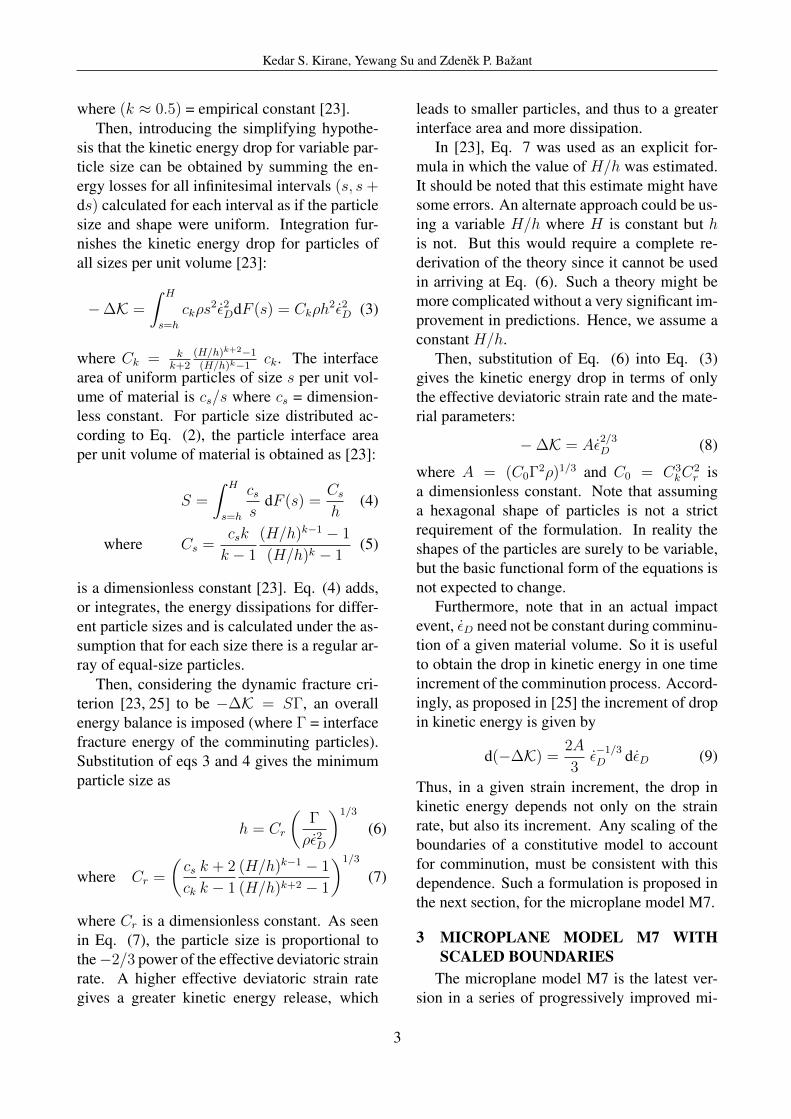
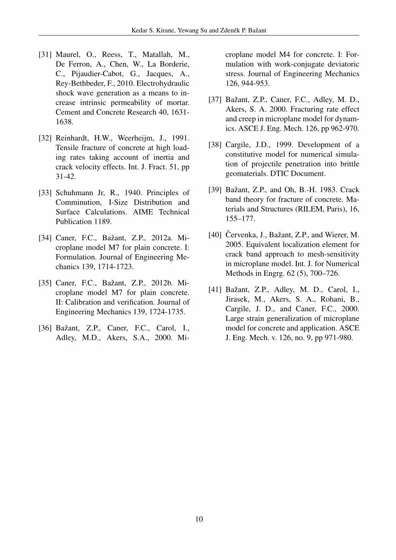
Consider an idealized dynamic fracture pro-cess in which the solid is comminuted to iden-tical prismatic particles of length h and hexag-onal cross section of side h/2, at a deviatoricstrain rate εD (Fig. 1). Analysis of the kine-matics and comparison of the kinetic energy ofparticles before (Fig. 1b) and after (Fig. 1c) theinterface fracture showed [23] that, for a motionin the plane of maximum shear strain, the localkinetic energy of the particles that are about toform, per unit volume of material, ∆K, is ad-ditive to, and separable from, the global kineticenergy.
The global kinetic energy corresponds to themotion of the centers of the particles whose for-mation is imminent. For a given εD, the dropin kinetic energy per unit volume is found tobe [23]:
−∆K = ckρh2ε2D (1)
where ck = Ip/(2hVp), ρ = mass density,Vp = 3
√3h3/8 and Ip = 5
√3h4/128 = volume
and polar moment of inertia of each hexagonalprism about its axis, respectively.
In reality, the size of comminuted particles isnever uniform but varies randomly within a cer-tain range, s ∈ (h,H) where h,H = minimumand maximum sizes, and s = variable particlesize. Schuhmann’s empirical power law [33] isadopted to describe the cumulative distribution.It gives the volume fraction of particles of sizesbetween h to s:
F (s) =sk − hk
Hk − hk, s ∈ (h,H), F (s) ∈ (0, 1)
(2)
2
Kedar S. Kirane, Yewang Su and Zdenek P. Bazant
where (k ≈ 0.5) = empirical constant [23].Then, introducing the simplifying hypothe-
sis that the kinetic energy drop for variable par-ticle size can be obtained by summing the en-ergy losses for all infinitesimal intervals (s, s+ds) calculated for each interval as if the particlesize and shape were uniform. Integration fur-nishes the kinetic energy drop for particles ofall sizes per unit volume [23]:
−∆K =
∫ H
s=h
ckρs2ε2DdF (s) = Ckρh
2ε2D (3)
where Ck = kk+2
(H/h)k+2−1(H/h)k−1
ck. The interfacearea of uniform particles of size s per unit vol-ume of material is cs/s where cs = dimension-less constant. For particle size distributed ac-cording to Eq. (2), the particle interface areaper unit volume of material is obtained as [23]:
S =
∫ H
s=h
css
dF (s) =Cs
h(4)
where Cs =csk
k − 1
(H/h)k−1 − 1
(H/h)k − 1(5)
is a dimensionless constant [23]. Eq. (4) adds,or integrates, the energy dissipations for differ-ent particle sizes and is calculated under the as-sumption that for each size there is a regular ar-ray of equal-size particles.
Then, considering the dynamic fracture cri-terion [23, 25] to be −∆K = SΓ, an overallenergy balance is imposed (where Γ = interfacefracture energy of the comminuting particles).Substitution of eqs 3 and 4 gives the minimumparticle size as
h = Cr
(Γ
ρε2D
)1/3
(6)
where Cr =
(csck
k + 2
k − 1
(H/h)k−1 − 1
(H/h)k+2 − 1
)1/3
(7)
where Cr is a dimensionless constant. As seenin Eq. (7), the particle size is proportional tothe−2/3 power of the effective deviatoric strainrate. A higher effective deviatoric strain rategives a greater kinetic energy release, which
leads to smaller particles, and thus to a greaterinterface area and more dissipation.
In [23], Eq. 7 was used as an explicit for-mula in which the value of H/h was estimated.It should be noted that this estimate might havesome errors. An alternate approach could be us-ing a variable H/h where H is constant but his not. But this would require a complete re-derivation of the theory since it cannot be usedin arriving at Eq. (6). Such a theory might bemore complicated without a very significant im-provement in predictions. Hence, we assume aconstant H/h.
Then, substitution of Eq. (6) into Eq. (3)gives the kinetic energy drop in terms of onlythe effective deviatoric strain rate and the mate-rial parameters:
−∆K = Aε2/3D (8)
where A = (C0Γ2ρ)1/3 and C0 = C3kC
2r is
a dimensionless constant. Note that assuminga hexagonal shape of particles is not a strictrequirement of the formulation. In reality theshapes of the particles are surely to be variable,but the basic functional form of the equations isnot expected to change.
Furthermore, note that in an actual impactevent, εD need not be constant during comminu-tion of a given material volume. So it is usefulto obtain the drop in kinetic energy in one timeincrement of the comminution process. Accord-ingly, as proposed in [25] the increment of dropin kinetic energy is given by
d(−∆K) =2A
3ε−1/3D dεD (9)
Thus, in a given strain increment, the drop inkinetic energy depends not only on the strainrate, but also its increment. Any scaling of theboundaries of a constitutive model to accountfor comminution, must be consistent with thisdependence. Such a formulation is proposed inthe next section, for the microplane model M7.
3 MICROPLANE MODEL M7 WITHSCALED BOUNDARIES
The microplane model M7 is the latest ver-sion in a series of progressively improved mi-
3

Kedar S. Kirane, Yewang Su and Zdenek P. Bazant
croplane models developed first for concreteand then extended to other quasibrittle mate-rials. The microplane model, supplementedby a suitable localization limiter with materialcharacteristic length, has been proven to giverather realistic predictions of the constitutiveand damage behavior of quasi-brittle materialsover a broad range of loading scenarios, in-cluding uniaxial, biaxial and triaxial loadingswith post-peak softening, compression-tensionload cycles, opening and mixed mode fractures,tension-shear failure and axial compression fol-lowed by torsion [34, 35].
The basic idea of the microplane model is toexpress the constitutive law not in terms of ten-sors, but in terms of the vectors of stress andstrain acting on a generic plane of any orien-tation in the material microstructure, called themicroplane. The use of vectors is analogous tothe Taylor models used for plasticity of poly-crystalline metals, but with important concep-tual differences. Firstly, to avoid model insta-bility in post-peak softening, a kinematic con-straint is used instead of a static one [34]. Thus,the strain (rather than stress) vector on each mi-croplane is the projection of the macroscopicstrain tensor. So we have,
εN = εijNij εM = εijMij εL = εijLij (10)
where εN , εM and εL are the magnitudes of thethree strain vectors corresponding to each mi-croplane, and Nij = ninj , Mij = (nimj +minj)/2 and Lij = (nilj + linj)/2, n, m, andl being the three mutually orthogonal normaland tangential vectors characterizing that mi-croplane, and the subscripts i and j=1,2,3. Sec-ondly, a variational principle (principle of vir-tual work) is used to relate the stresses on themicroplanes (σN , σM and σL) to the macro-continuum stress tensor σij , to ensure equilib-rium and is expressed as,
2π
3σijδεij =
∫Ω
σNδεN + σMδεM + σLδεLdΩ
(11)This expression means that, within a unit
sphere, the virtual works of macro-stresses and
micro-stresses must be equal (for details, see[34, 36]). In the microplane model M7, themicro-stresses are subjected to strain dependentboundaries (or strength limits) of four types,viz.:
1. The tensile normal boundary—to captureprogressive tensile fracturing;
2. The compressive volumetric boundary—to capture phenomena such as pore col-lapse under extreme pressures;
3. The compressive deviatoric boundary—to capture softening in compression; and
4. The shear boundary—to capture friction.
The M7 also includes the quasi-static rateeffects [37], which consist of a rate-dependentcrack opening and growth controlled by the ac-tivation energy of bond breakage, and of visco-elasticity of the material between the cracks.However, the quasi-static rate effects sufficeonly up the strain rate of about 1/s, which is in-sufficient for impact.
Since comminution is induced by local shearstrains, we assume that in a given strain incre-ment dεij , the additional energy to be dissipatedmust equal the additional distortional strain en-ergy given by ∆σDij εDij where ∆σDij is theadditional deviatoric stress that results due toscaled boundaries. To express it in terms of themicroplane stresses, we first define the volumet-ric stress on the microplane level, σV , as
2π
3
σkk3δεmm =
∫Ω
σV δεV dΩ (12)
Substituting δεV = δεmm/3 and∫
Ω= 2π, the
volumetric stress on the microplane level canbe expressed as σV = σkk/3. Also, the mi-croplane normal stresses σN = σD + σV whereσD is the deviatoric stress on the microplanelevel. Likewise, for microplane strains, we haveεN = εD +εV . Note that εV = εkk/3 is the samefor all microplanes.
Then, subtracting Eq. (12) from (11) and
4
Kedar S. Kirane, Yewang Su and Zdenek P. Bazant
noting that∫
ΩσDδεV =
∫ΩσV δεD = 0, we get
2π
3σDijδεij =
∫Ω
σDδεD + σMδεM + σLδεLdΩ
(13)Then, since δεD = δεN − δεV = δεijNij −
δεijδij/3, δεM = δεijMij and δεL = δεijLij , weget an expression for the macroscale deviatoricstress tensor as,
2π
3σDij =∫
Ω
σD
(Nij −
δij
3
)+ σMMij + σLLijdΩ
(14)
This expression implies that a change in themacro-scale deviatoric stress can be achievedby scaling only the deviatoric and frictionalboundaries of M7. Let the change in the mi-croplane deviatoric and shear stresses be ∆σD,∆σM and ∆σL for a change in deviatoric stressof ∆σDij . So we have,
2π
3∆σDij =∫
Ω
∆σD
(Nij −
δij
3
)+ ∆σMMij + ∆σLLijdΩ
(15)
Now, in the interest of simplicity, we assumethat both the deviatoric and frictional bound-aries are scaled by the same amount, on eachmicroplane. So, ∆σD = ∆σM = ∆σL = ∆f ,and
2π
3∆σDij =∫
Ω
∆f
(Nij −
δij
3
)+ ∆fMij + ∆fLijdΩ
(16)
This may be simplified as,
∆σDij = ∆fCij (17)
where,
Cij =3
2π
∫Ω
(Nij −
δij
3
)+Mij + LijdΩ
(18)
which is constant. ∆f may be taken out of theintegral since we assume it to be the same foreach microplane. Now, the next task is to re-late the quantity ∆f to the energy dissipateddue to comminution, ∆K. To ensure the afore-mentioned energy balance, the work of the addi-tional deviatoric stress must dissipate an energyequal to the drop of kinetic energy of strain ratefield caused by comminution in each increment.So,
d(−∆K) = ∆σDijdεDij (19)
where i, j = 1, 2, 3 and d denotes a small incre-ment. So we have
d(−∆K) = ∆f CijdεDij (20)
Next, using eq. 9 and taking the derivativewith respect to time on both sides, we get
2A
3ε−1/3D εD = ∆f Cij εDij (21)
Multiplying both sides by εDij , we obtain
2A
3ε−1/3D εD εDij = 2∆f Cij ε
2D (22)
since εD =√εij εij/2. Thus we have,
∆f Cij =A
3ε−7/3D εD εDij (23)
Note that the right-hand side of this expres-sion is consistent with [25]. To obtain the scalarvalue ∆f , we now calculate the effective valuesof both sides, by taking square root of the innerproduct with itself. So we have,
∆f (CijCij)1/2 =
√2A
3ε−7/3D εD εD (24)
Thus the scalar ∆f is expressed as,
∆f = A1ε−4/3D εD (25)
Here A1 is a constant to be calibrated, and isgiven by A1 =
√2A/3C and C =
√CijCij .
Therefore, the deviatoric and frictional bound-aries of M7 are scaled as F = Fqs(1 +
A1ε−4/3D εD), where Fqs = F0(1 + h(ε)), the
5

Kedar S. Kirane, Yewang Su and Zdenek P. Bazant
boundary that is already scaled to account forthe quasi-static rate effects [37], and F0 is theoriginal unscaled M7 boundary. This expres-sion shows that, to capture the energy dissipa-tion due to comminution, it is necessary to makethe boundary a function of both the first and sec-ond time derivatives of the effective deviatoricstrain.
4 CONCRETE SLAB PERFORATIONBY PROJECTILE IMPACT
The M7 model with scaled boundaries wasevaluated using the tests of projectile perfora-tion, performed at the Geo-technical and Struc-ture Laboratory of the US. Army Engineer Re-search and Development center (ERDC), Vicks-burg [8, 38]. These tests used circular slabs offour thicknesses, 127, 216, 254 mm and 280mm, made of concrete WES-5000, whose stan-dard compression strength was 48 MPa. Theslabs were cast in steel culvert pipes of diam-eter 1.52 m, sufficient to approximate the re-sponse for a semi-infinite radius (in spite ofthat, non-reflecting finite elements producingno backward waves were used at the boundary).The projectiles, which were hollow and madeof steel, had an ogival-nose (caliber radius head3.0, length/diameter ratio 7.0, and diameter 50.8mm) and weight of 2.3 kg. The projectiles im-pacted the concrete slabs with the velocity of310 m/s at the angle of 90 degrees. The perfo-ration tests were carried out two or three timesfor each thickness of the slab.
First, the M7 model was calibrated to fit thetest data for concrete WES-5000, used in thesetests. This concrete had Young’s modulus E =25 GPa, and Poisson’s ratio µ = 0.18. The opti-mum values of M7 parameters, which achievedvery good fits of quasi-static uni-, bi- and tri-axial tests, were k1 = 11x10−5, k2 = 110, k3 =30, k4 = 100 and k5 = 10−4 [34, 35].
The mesh used to discretize the slabs wasrandom but statistically uniform, and consistedof tetrahedral elements of average size 7.5 mm.The projectile was considered rigid since noobvious damage, melt or deformation was ob-served after the test. To prevent spurious
mesh sensitivity, the modeling was performedin the sense of the crack band model, in whichthe finite element size (or mesh size) shouldbe equal to the material characteristic length,which characterizes the size of the representa-tive volume element (RVE) of the material andis used as the localization limiter. The elementsize was considered as 7.5 mm, which is about1-2 times the maximum aggregate size. Notethat if, in quasi-static problems, the element sizeis changed, the crack band model requires ad-justing the post-peak softening of the damageconstitutive law so that the energy dissipatedin the crack band (localized into one elementwidth) would not change [39] (which is what isdone in commercial software such as ATENA orOOFEM [40]). But, in projectile impact prob-lems, the deformation is generally so fast thatthere is not enough time for the cracking dam-age to localize, and so the post-peak of the dam-age law need not, and should not, be adjusted.
Also note that, while the apparent strengthand fracture energy depend on the strain rate,the crack band width itself does not. It is amaterial property that can be measured, e.g., asthe minimum possible spacing of parallel quasi-static macro-cracks. It depends on material het-erogeneity, and is usually equal to 1 to 3 maxi-mum inhomogeneity sizes. In dynamic fracture,where the localization is suppressed by high de-formation rates, the finite element solver basedon the crack band model automatically simu-lates (in a diffuse way, of course) the formationof multiple cracks and crack branching. The ad-ditional energy dissipation at very high strainrates is accounted for by material law adjust-ment, one type of which is presented here.
For these analyses, it was necessary to re-move excessively distorted elements to avoidtermination of analysis due to negative Jaco-bian. This was done using an element dele-tion criterion based on the maximum principalstrain. Thresholds of the criterion were set in-dependently for tension and compression, to avalue such that a further increase of the thresh-old did not make a difference to the predictedexit velocities. These values turned out to be
6

Kedar S. Kirane, Yewang Su and Zdenek P. Bazant
40% for tensile strain and 100% for compres-sive strain as shown in [27].
Next, using the aforementioned elementdeletion criterion, the quasi-static rate effectswere employed, and the projectile exit veloci-ties were predicted (with the same parametersas mentioned in [24]). These effects mainlyrefer to the rate dependence of cohesive crackopening and follow from the activation energytheory of bond ruptures. These effects are ac-counted for by scaling all the boundaries of M7as Fqs = F0(1 + CR2ln(2ε/CR1)) [37], where
ε =√
12εij εij . The parameter values CR1 and
CR2 were determined in [24] to be 4 × 10⁻⁶
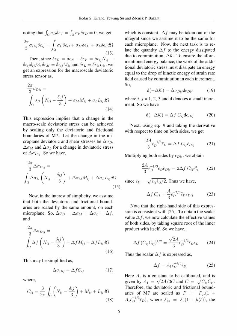
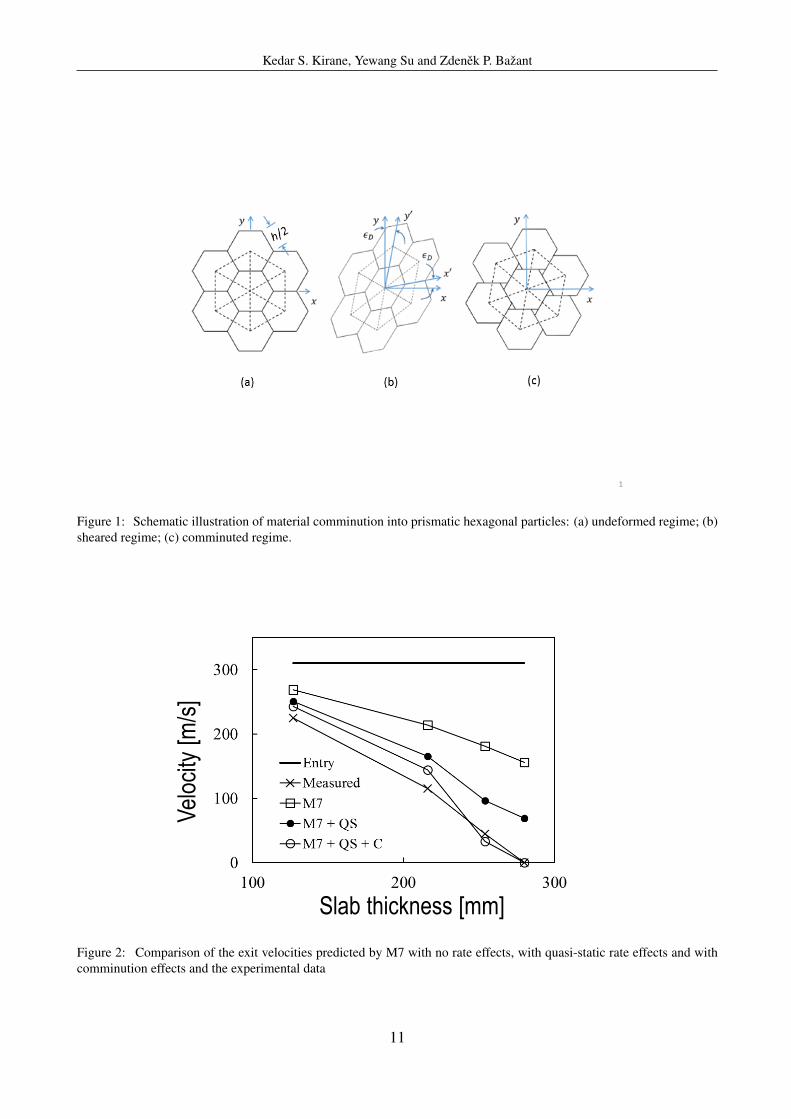
and 0.022 respectively. The exit velocities wereagain predicted by including these effects, asshown in Fig. 3. It is seen that these effectscaused the predicted velocities to change signif-icantly. However, it is seen that the quasi-staticrate effects still do not suffice to correctly pre-dict the exit velocities. So, we now add the ef-fects of comminution by scaling the deviatoricand friction boundaries of M7, as described ear-lier.
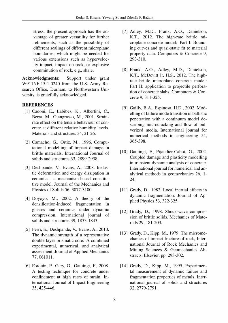
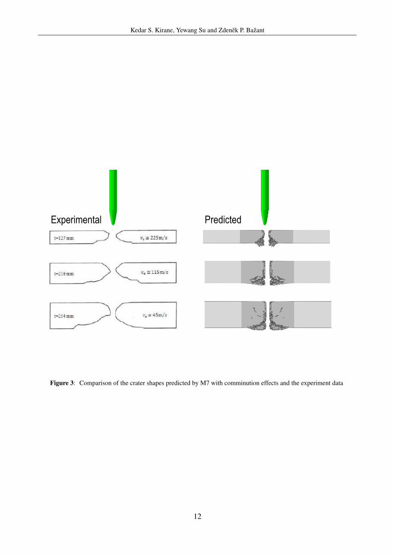
Parameter A1 was calibrated by fitting onedata point in Fig. 2, which led to the valueA1 = 3×10⁻⁷. The remaining points were thenpredicted. Fig. 2 shows the predicted exit ve-locities for all four slabs tested. As can be seen,the predictions of exit velocities are reasonablygood, for all the data points. For the smallerslabs, the exit velocity is slightly overestimatedwhile for the larger slab it is slightly underes-timated. The fit could further be improved byrelaxing the assumption that both the deviatoricand friction boundaries are scaled by the samefactor. But this has not been explored since theerrors are small and the data are too limited forcalibrating two factors. To further assess thepredictions, the predicted crater shapes for theslabs are compared to the measured ones, asshown in Fig. 3. It can be seen that the shapescan be matched very well, especially those atthe exit side. This serves to show that the pro-posed scaling of M7 boundaries accounts forthe phenomenon of comminution quite well.
5 CONCLUSIONS1. The microplane model M7 with bound-
aries modified according to the kineticenergy theory of comminution is an effec-tive approach to simulate projectile im-pact effects on concrete slabs and offerspossibilities of further refinement. It canaccurately predict projectile exit veloci-ties, crater shapes and penetration depths.
2. It is necessary to scale up the deviatoricand friction boundaries of M7, to achievea rate-dependent increase of the macro-scopic deviatoric stress. Greater versatil-ity could be obtained by scaling up thedeviatoric and friction boundaries by dif-ferent factors. But there are not enoughtest data to calibrate two independent fac-tors.
3. The scaling of the boundaries (or strengthlimits) must be proportional to both: 1)the −4/3 power of the effective devia-toric strain rate, and 2) the time derivativeof that rate.
4. The crack band model with a randomtetrahedral mesh leads to accurate predic-tions of the crater shapes.
5. An element deletion threshold is neces-sary to run impact analyses. The choiceof the threshold has a significant effect onthe results. Chosen is high enough thresh-old for maximum principal strain suchthat a further increase would not changethe results appreciably.
6. What is most important is that the finiteelement code dissipate the correct energyrequired by the kinetic theory of com-minution. But how exactly this energy isdissipated does not seem important. Dis-sipation modes in terms of additional vis-cosity, rate dependence of interface frac-ture, and scaling of strength limits givesimilar results. While the viscosity ap-proach is more natural for rate-dependent
7
Kedar S. Kirane, Yewang Su and Zdenek P. Bazant
stress, the present approach has the ad-vantage of greater versatility for furtherrefinements, such as the possibility ofdifferent scalings of different microplaneboundaries, which might be needed forvarious extensions such as hyperveloc-ity impact, impact on rock, or explosivecomminution of rock, e.g., shale.
Acknowledgments: Support under grantW911NF-15-1-0240 from the U.S. Army Re-search Office, Durham, to Northwestern Uni-versity, is gratefully acknowledged.
REFERENCES[1] Cadoni, E., Labibes, K., Albertini, C.,
Berra, M., Giangrasso, M., 2001. Strain-rate effect on the tensile behaviour of con-crete at different relative humidity levels.Materials and structures 34, 21-26.
[2] Camacho, G., Ortiz, M., 1996. Compu-tational modelling of impact damage inbrittle materials. International Journal ofsolids and structures 33, 2899-2938.
[3] Deshpande, V., Evans, A., 2008. Inelas-tic deformation and energy dissipation inceramics: a mechanism-based constitu-tive model. Journal of the Mechanics andPhysics of Solids 56, 3077-3100.
[4] Doyoyo, M., 2002. A theory of thedensification-induced fragmentation inglasses and ceramics under dynamiccompression. International journal ofsolids and structures 39, 1833-1843.
[5] Ferri, E., Deshpande, V., Evans, A., 2010.The dynamic strength of a representativedouble layer prismatic core: A combinedexperimental, numerical, and analyticalassessment. Journal of Applied Mechanics77, 061011.
[6] Forquin, P., Gary, G., Gatuingt, F., 2008.A testing technique for concrete underconfinement at high rates of strain. In-ternational Journal of Impact Engineering35, 425-446.
[7] Adley, M.D., Frank, A.O., Danielson,K.T., 2012. The high-rate brittle mi-croplane concrete model: Part I: Bound-ing curves and quasi-static fit to materialproperty data. Computers & Concrete 9,293-310.
[8] Frank, A.O., Adley, M.D., Danielson,K.T., McDevitt Jr, H.S., 2012. The high-rate brittle microplane concrete model:Part II: application to projectile perfora-tion of concrete slabs. Computers & Con-crete 9, 311-325.
[9] Gailly, B.A., Espinosa, H.D., 2002. Mod-elling of failure mode transition in ballisticpenetration with a continuum model de-scribing microcracking and flow of pul-verized media. International journal fornumerical methods in engineering 54,365-398.
[10] Gatuingt, F., Pijaudier-Cabot, G., 2002.Coupled damage and plasticity modellingin transient dynamic analysis of concrete.International journal for numerical and an-alytical methods in geomechanics 26, 1-24.
[11] Grady, D., 1982. Local inertial effects indynamic fragmentation. Journal of Ap-plied Physics 53, 322-325.
[12] Grady, D., 1998. Shock-wave compres-sion of brittle solids. Mechanics of Mate-rials 29, 181-203.
[13] Grady, D., Kipp, M., 1979. The microme-chanics of impact fracture of rock, Inter-national Journal of Rock Mechanics andMining Sciences & Geomechanics Ab-stracts. Elsevier, pp. 293-302.
[14] Grady, D., Kipp, M., 1995. Experimen-tal measurement of dynamic failure andfragmentation properties of metals. Inter-national journal of solids and structures32, 2779-2791.
8

Kedar S. Kirane, Yewang Su and Zdenek P. Bazant
[15] Grady, D.E., 1990. Particle size statisticsin dynamic fragmentation. Journal of ap-plied physics 68, 6099-6105.
[16] Kozar, I., Ozbolt, J., 2010. Some aspectsof load-rate sensitivity in visco-elastic mi-croplane material model. Computers andConcrete 7(4), pp.317-329.
[17] Mescall, J., Weiss, V., 1984. Materialsbehavior under high stress and ultrahighloading ratesPart II, Proceeding of 29thSagamore Army Conference, Army Ma-terials and Mechanics Center, Watertown,MA.
[18] Mott, N., 1947. Fragmentation of shellcases. Proceedings of the Royal Societyof London. Series A. Mathematical andPhysical Sciences 189, 300-308.
[19] Ozbolt, J., Sharma, A., Reinhardt, H.-W.,2011. Dynamic fracture of concrete com-pact tension specimen. International Jour-nal of Solids and Structures 48, 1534-1543.
[20] Shih, C., Nesterenko, V., Meyers, M.,1998. High-strain-rate deformation andcomminution of silicon carbide. Journal ofapplied physics 83, 4660-4671.
[21] Wei, Z., Evans, A., Deshpande, V., 2009.The influence of material properties andconfinement on the dynamic penetrationof alumina by hard spheres. Journal of Ap-plied Mechanics 76, 051305.
[22] Bazant, Z.P., Caner, F.C., 2013. Com-minution of solids caused by kinetic en-ergy of high shear strain rate, with im-plications for impact, shock, and shalefracturing. Proceedings of the NationalAcademy of Sciences 110, 19291-19294.
[23] Bazant, Z.P., Caner, F.C., 2014. Impactcomminution of solids due to local kinetic
energy of high shear strain rate: I. Contin-uum theory and turbulence analogy. Jour-nal of the Mechanics and Physics of Solids64, 223-235.
[24] Caner, F.C., Bazant, Z.P., 2014. Impactcomminution of solids due to local kineticenergy of high shear strain rate: II. Mi-croplane model and verification. Journalof the Mechanics and Physics of Solids 64,236-248.
[25] Su, Y., Bazant, Z.P., Zhao, Y., Salviato.M., Kirane., K., 2015. Viscous energydissipation of kinetic energy of particlescomminuted by high-rate shearing in pro-jectile penetration, with potential ramifi-cation to gas shale. Int. J. Fract. 51, pp 31-42.
[26] Bazant, Z.P., Su, Y., 2015. Impact com-minution of solids due to progressivecrack growth driven by kinetic energy ofhigh-rate shear. ASME J. of Applied Me-chanics 82, 031007-1–031007-5.
[27] Kirane, K., Su, Yewang, Bazant, Z.P.(2015). Strain-rate-dependent microplanemodel for high-rate comminution of con-crete under impact based on kinetic en-ergy release theory. Proc. Royal Soc. A,471 (2182), 20150535.
[28] Freund, L.B. (1990). Dynamic FractureMechanics. Cambridge University Press,Cambridge, U.K.
[29] Shockey, D. A., Curran, D. R., Seaman,L., Rosenberg, J. T., Petersen, C. F., 1974.Fragmentation of Rock under DynamicLoads. Int. J. Rock Mech. Sci. and Ge-omech. Abstr. Vol. 11, pp. 303-317.
[30] Hemmert, D.J., Smirnov, V.I., Awal, R.,Lati, S., Shetty, A., 2010. Pulsed powergenerated shockwaves in liquids from ex-ploding wires and foils for industrial ap-plications, Proceedings of the 16th In-ternational Symposium on High CurrentElectronics (Tomsk, Russia), pp. 537-540.
9
Kedar S. Kirane, Yewang Su and Zdenek P. Bazant
[31] Maurel, O., Reess, T., Matallah, M.,De Ferron, A., Chen, W., La Borderie,C., Pijaudier-Cabot, G., Jacques, A.,Rey-Bethbeder, F., 2010. Electrohydraulicshock wave generation as a means to in-crease intrinsic permeability of mortar.Cement and Concrete Research 40, 1631-1638.
[32] Reinhardt, H.W., Weerheijm, J., 1991.Tensile fracture of concrete at high load-ing rates taking account of inertia andcrack velocity effects. Int. J. Fract. 51, pp31-42.
[33] Schuhmann Jr, R., 1940. Principles ofComminution, I-Size Distribution andSurface Calculations. AIME TechnicalPublication 1189.
[34] Caner, F.C., Bazant, Z.P., 2012a. Mi-croplane model M7 for plain concrete. I:Formulation. Journal of Engineering Me-chanics 139, 1714-1723.
[35] Caner, F.C., Bazant, Z.P., 2012b. Mi-croplane model M7 for plain concrete.II: Calibration and verification. Journal ofEngineering Mechanics 139, 1724-1735.
[36] Bazant, Z.P., Caner, F.C., Carol, I.,Adley, M.D., Akers, S.A., 2000. Mi-
croplane model M4 for concrete. I: For-mulation with work-conjugate deviatoricstress. Journal of Engineering Mechanics126, 944-953.
[37] Bazant, Z.P., Caner, F.C., Adley, M. D.,Akers, S. A. 2000. Fracturing rate effectand creep in microplane model for dynam-ics. ASCE J. Eng. Mech. 126, pp 962-970.
[38] Cargile, J.D., 1999. Development of aconstitutive model for numerical simula-tion of projectile penetration into brittlegeomaterials. DTIC Document.
[39] Bazant, Z.P., and Oh, B.-H. 1983. Crackband theory for fracture of concrete. Ma-terials and Structures (RILEM, Paris), 16,155–177.
[40] Cervenka, J., Bazant, Z.P., and Wierer, M.2005. Equivalent localization element forcrack band approach to mesh-sensitivityin microplane model. Int. J. for NumericalMethods in Engrg. 62 (5), 700–726.
[41] Bazant, Z.P., Adley, M. D., Carol, I.,Jirasek, M., Akers, S. A., Rohani, B.,Cargile, J. D., and Caner, F.C., 2000.Large strain generalization of microplanemodel for concrete and application. ASCEJ. Eng. Mech. v. 126, no. 9, pp 971-980.
10
Kedar S. Kirane, Yewang Su and Zdenek P. Bazant
1
Figure 1: Schematic illustration of material comminution into prismatic hexagonal particles: (a) undeformed regime; (b)sheared regime; (c) comminuted regime.
Vel
ocity
[m
/s]
Slab thickness [mm]
3
Figure 2: Comparison of the exit velocities predicted by M7 with no rate effects, with quasi-static rate effects and withcomminution effects and the experimental data
11
Kedar S. Kirane, Yewang Su and Zdenek P. Bazant
Experimental Predicted
4
Figure 3: Comparison of the crater shapes predicted by M7 with comminution effects and the experiment data
12