Lexington-Fayette County as a Study Area for Examining Urban Growth Management Policies

Stormwater Manual
Lexington-Fayette Urban County Government Lexington, Kentucky
January 1, 2009

CHAPTER 1 PURPOSE AND OVERVIEW

STORMWATER MANUAL 1-1 January 1, 2009 LEXINGTON-FAYETTE CO., KY.
1.1 Introduction Chapter 1 gives the purpose of this manual and an overview of the standards for stormwater management in Fayette County. Three concepts, the public drainage system, the waters of Fayette County, and post-development floodplains are important to the management of stormwater and are discussed in this chapter. The chapter also includes several general criteria required for the management of stormwater in new development. Finally, the chapter includes a summary of the specific criteria for managing water quantity and water quality. Many of the criteria presented in Chapter 1 are discussed in more detail in later chapters.
The manual is applicable to all stormwater infrastructure owned or regulated by the Lexington-Fayette Urban County Government (LFUCG). This includes infrastructure on commercial and industrial property. The only stormwater infrastructure not covered by the manual is farm facilities used for agricultural purposes.

STORMWATER MANUAL 1-2 January 1, 2009 LEXINGTON-FAYETTE CO., KY.
1.2 Purpose The regulated stormwater in Fayette County lies on both public and private property. Portions of the stormwater infrastructure are constructed through the LFUCG capital improvement projects and portions are constructed through private residential, commercial, and industrial development. In many cases, the LFUCG may ultimately become the owner of the stormwater infrastructure constructed by private development. To responsibly regulate the stormwater infrastructure, a consistent quality of construction is necessary regardless of the entity financing and managing the construction. The purpose of this manual is to provide standards to assure quality in the design and construction of stormwater infrastructure that becomes a part of that owned or regulated by the LFUCG by providing standard design criteria to the engineers who design the infrastructure. The manual establishes uniformity in design assumptions and general methods of design. The manual also sets policy regarding design standards and specifications and provides for uniform interpretation of the specifications. Finally, the manual outlines the required calculations and design details applicable to all stormwater infrastructure. This manual draws heavily on technical information and design criteria used in numerous city and state manuals and is thus similar in many instances to those manuals. However, this manual has been tailored to fit Lexington and Fayette County and contains important provisions that are unique to this area. The manual includes requirements for the stormwater infrastructure that is routinely designed and constructed, including rational engineering principles and practices. However, more comprehensive methods of analysis and design may be required for unusual conditions not specifically covered in this manual or where otherwise appropriate from an engineering standpoint to assure public safety and quality in infrastructure design and construction.
STORMWATER MANUAL 1-3 January 1, 2009 LEXINGTON-FAYETTE CO., KY.
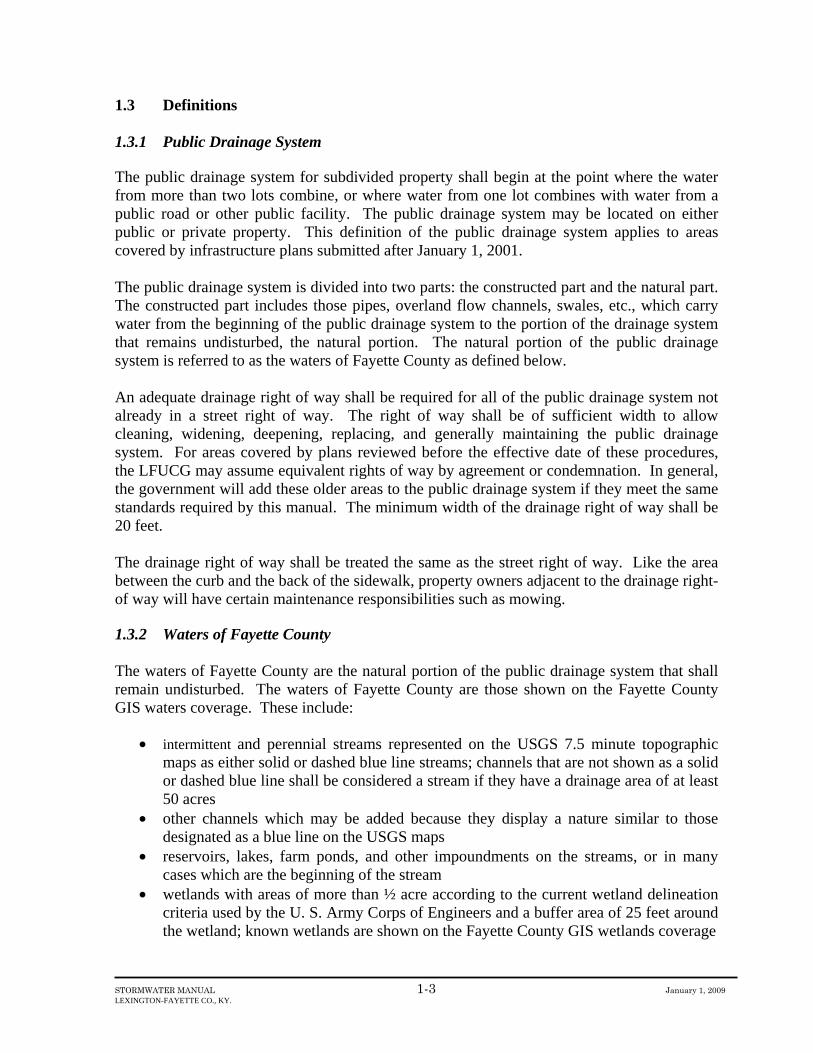
1.3 Definitions 1.3.1 Public Drainage System The public drainage system for subdivided property shall begin at the point where the water from more than two lots combine, or where water from one lot combines with water from a public road or other public facility. The public drainage system may be located on either public or private property. This definition of the public drainage system applies to areas covered by infrastructure plans submitted after January 1, 2001. The public drainage system is divided into two parts: the constructed part and the natural part. The constructed part includes those pipes, overland flow channels, swales, etc., which carry water from the beginning of the public drainage system to the portion of the drainage system that remains undisturbed, the natural portion. The natural portion of the public drainage system is referred to as the waters of Fayette County as defined below. An adequate drainage right of way shall be required for all of the public drainage system not already in a street right of way. The right of way shall be of sufficient width to allow cleaning, widening, deepening, replacing, and generally maintaining the public drainage system. For areas covered by plans reviewed before the effective date of these procedures, the LFUCG may assume equivalent rights of way by agreement or condemnation. In general, the government will add these older areas to the public drainage system if they meet the same standards required by this manual. The minimum width of the drainage right of way shall be 20 feet. The drainage right of way shall be treated the same as the street right of way. Like the area between the curb and the back of the sidewalk, property owners adjacent to the drainage right-of way will have certain maintenance responsibilities such as mowing. 1.3.2 Waters of Fayette County The waters of Fayette County are the natural portion of the public drainage system that shall remain undisturbed. The waters of Fayette County are those shown on the Fayette County GIS waters coverage. These include:
• intermittent and perennial streams represented on the USGS 7.5 minute topographic
maps as either solid or dashed blue line streams; channels that are not shown as a solid or dashed blue line shall be considered a stream if they have a drainage area of at least 50 acres
• other channels which may be added because they display a nature similar to those designated as a blue line on the USGS maps
• reservoirs, lakes, farm ponds, and other impoundments on the streams, or in many cases which are the beginning of the stream
• wetlands with areas of more than ½ acre according to the current wetland delineation criteria used by the U. S. Army Corps of Engineers and a buffer area of 25 feet around the wetland; known wetlands are shown on the Fayette County GIS wetlands coverage
STORMWATER MANUAL 1-4 January 1, 2009 LEXINGTON-FAYETTE CO., KY.
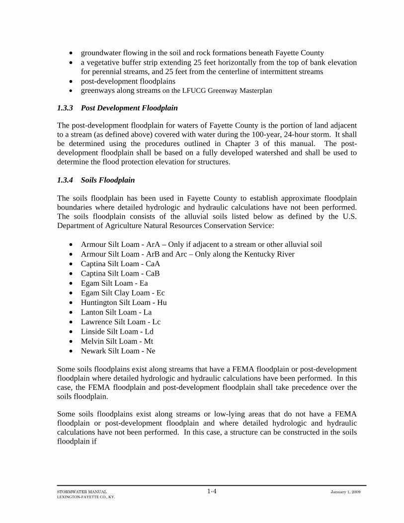
• groundwater flowing in the soil and rock formations beneath Fayette County • a vegetative buffer strip extending 25 feet horizontally from the top of bank elevation
for perennial streams, and 25 feet from the centerline of intermittent streams • post-development floodplains • greenways along streams on the LFUCG Greenway Masterplan
1.3.3 Post Development Floodplain The post-development floodplain for waters of Fayette County is the portion of land adjacent to a stream (as defined above) covered with water during the 100-year, 24-hour storm. It shall be determined using the procedures outlined in Chapter 3 of this manual. The post-development floodplain shall be based on a fully developed watershed and shall be used to determine the flood protection elevation for structures. 1.3.4 Soils Floodplain The soils floodplain has been used in Fayette County to establish approximate floodplain boundaries where detailed hydrologic and hydraulic calculations have not been performed. The soils floodplain consists of the alluvial soils listed below as defined by the U.S. Department of Agriculture Natural Resources Conservation Service:
• Armour Silt Loam - ArA – Only if adjacent to a stream or other alluvial soil • Armour Silt Loam - ArB and Arc – Only along the Kentucky River • Captina Silt Loam - CaA • Captina Silt Loam - CaB • Egam Silt Loam - Ea • Egam Silt Clay Loam - Ec • Huntington Silt Loam - Hu • Lanton Silt Loam - La • Lawrence Silt Loam - Lc • Linside Silt Loam - Ld • Melvin Silt Loam - Mt • Newark Silt Loam - Ne
Some soils floodplains exist along streams that have a FEMA floodplain or post-development floodplain where detailed hydrologic and hydraulic calculations have been performed. In this case, the FEMA floodplain and post-development floodplain shall take precedence over the soils floodplain. Some soils floodplains exist along streams or low-lying areas that do not have a FEMA floodplain or post-development floodplain and where detailed hydrologic and hydraulic calculations have not been performed. In this case, a structure can be constructed in the soils floodplain if

STORMWATER MANUAL 1-5 January 1, 2009 LEXINGTON-FAYETTE CO., KY.
• the Division of Engineering determines that the proposed structure will not flood for the 100-year storm, will not create a drainage problem, and will not aggravate an existing problem
• a foundation design, stamped by a professional engineer licensed in Kentucky, is submitted as part of the application for a building permit to the Division of Building Inspection

STORMWATER MANUAL 1-6 January 1, 2009 LEXINGTON-FAYETTE CO., KY.
1.4 General Criteria for New Development 1.4.1 Watershed Studies Watershed studies are necessary to evaluate the impacts of a given development on the public drainage system and to define the post-development floodplain. The criteria for conducting watershed studies are given in Chapter 3. The LFUCG has a program for inventorying the stormwater system, collecting physical and chemical data describing the waters, and developing watershed models. The program also includes collecting information on the physical nature of the stream or channel, detail of the natural vegetation in the floodplain, the riparian vegetation, the nature and extent of any unique features like wetlands, and the biological community in the water. In watersheds where the models are completed, the LFUCG shall define the post development floodplain and set the other stormwater criteria for the development. In areas where the models are not completed, the LFUCG may require the Developer to conduct the study. 1.4.2 Regional Stormwater Management The LFUCG shall require regional stormwater management facilities when practicable. This is more cost effective than requiring each small development project to construct its own stormwater facilities. In addition, the long-term maintenance requirements will be less because there will be fewer of these small facilities to maintain. The LFUCG may require two or more developers to jointly fund the construction of a common water quality and/or water quantity practice by requiring cooperation between the developers or using a fee-in-lieu of constructing stormwater BMPs as defined later in this chapter. 1.4.3 Existing Stormwater Master Plans Expansion Area 2 The regional stormwater master plan for Expansion Area 2 is contained in a report prepared by Commonwealth Technology, Inc. entitled “Preliminary Engineering Report – Stormwater Management in Expansion Area 2.” This report can be obtained from the Division of Engineering. The report contains the location and size of stormwater management structures to control flooding and to protect water quality.
Stormwater Master Plans Prepared by Developers The following developments currently have a regional stormwater master plan to control flooding:
• Beaumont Centre • Coldstream • Hamburg • Reynolds Road
STORMWATER MANUAL 1-7 January 1, 2009 LEXINGTON-FAYETTE CO., KY.
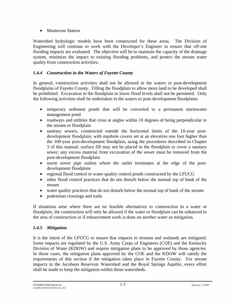
• Masterson Station Watershed hydrologic models have been constructed for these areas. The Division of Engineering will continue to work with the Developer’s Engineer to ensure that off-site flooding impacts are evaluated. The objective will be to maintain the capacity of the drainage system, minimize the impact to existing flooding problems, and protect the stream water quality from construction activities. 1.4.4 Construction in the Waters of Fayette County In general, construction activities shall not be allowed in the waters or post-development floodplains of Fayette County. Filling the floodplain to allow more land to be developed shall be prohibited. Excavation in the floodplain to lower flood levels shall not be permitted. Only the following activities shall be undertaken in the waters or post-development floodplains
• temporary sediment ponds that will be converted to a permanent stormwater
management pond • roadways and utilities that cross at angles within 10 degrees of being perpendicular to
the stream or floodplain • sanitary sewers, constructed outside the horizontal limits of the 10-year post-
development floodplain, with manhole covers set at an elevation one foot higher than the 100-year post-development floodplain, using the procedures described in Chapter 3 of this manual; surface fill may not be placed in the floodplain to cover a sanitary sewer; any excess material from excavation of the sewer must be removed from the post-development floodplain
• storm sewer pipe outlets where the outlet terminates at the edge of the post-development floodplain
• regional flood control or water quality control ponds constructed by the LFUCG • other flood control practices that do not disturb below the normal top of bank of the
stream • water quality practices that do not disturb below the normal top of bank of the stream • pedestrian crossings and trails
If situations arise where there are no feasible alternatives to construction in a water or floodplain, the construction will only be allowed if the water or floodplain can be enhanced in the area of construction or if enhancement work is done on another water as mitigation. 1.4.5 Mitigation It is the intent of the LFUCG to ensure that impacts to streams and wetlands are mitigated. Some impacts are regulated by the U.S. Army Corps of Engineers (COE) and the Kentucky Division of Water (KDOW) and require mitigation plans to be approved by those agencies. In those cases, the mitigation plans approved by the COE and the KDOW will satisfy the requirements of this section if the mitigation takes place in Fayette County. For stream impacts in the Jacobson Reservoir Watershed and the Royal Springs Aquifer, every effort shall be made to keep the mitigation within those watersheds.

STORMWATER MANUAL 1-8 January 1, 2009 LEXINGTON-FAYETTE CO., KY.
In cases where neither the COE nor the KDOW regulate a stream or wetland impact, the following mitigation guidelines shall be followed: Fills Along a Stream > 200 Feet Fill for road crossings and embankments shall be mitigated by establishing a riparian buffer zone on each side of the stream for a length equal to the width of the post-development floodplain. Stream Relocations > 200 Feet The relocated stream shall be designed to:
• restore the geomorphic function, including the meandering pattern • include measures to enhance aquatic habitat • use natural or bioengineering techniques to stabilize banks • include a minimum 25 foot vegetative buffer strip on each side
Wetlands > 0.5 acre Mitigation shall take the form of creating another wetland at a ratio of 1:1, or obtaining credits in a LFUCG wetland bank. 1.4.6 Ownership of Stormwater Facilities For Improvement Plans submitted on or after January 1, 2001, the LFUCG shall own and maintain the facilities listed below in single family residential and two family residential developments:
• Dry Detention Ponds • Wet Detention Ponds • Extended Detention Ponds • Infiltration Basins • Constructed Wetlands
These facilities shall be on a separate lot with adequate access for maintenance and dedicated to the LFUCG. In multi-family residential developments, these facilities shall be owned and maintained by the LFUCG if they are on a separate lot with access to a public street. The property owner shall own and maintain stormwater Best Management Practices (BMPs) in commercial and industrial developments. The BMPs shall not be subdivided into multiple lots. Furthermore, they shall be connected to at least one building lot, but no more than one building lot. The purpose of these requirements is to ensure that:
• a citizen, group of citizens, or neighborhood association does not own or maintain a new detention pond or other BMP

STORMWATER MANUAL 1-9 January 1, 2009 LEXINGTON-FAYETTE CO., KY.
• only one corporation or business owns and maintains a detention pond or other BMP 1.4.7 Lot Drainage in Residential Development Constructed channels shall be provided for drainage areas greater than 1 acre in residential developments. The channel shall be designed to carry the 100-year storm to the stream. The drainage easement along the channel shall be 20 feet wide, or the width of the 100-year flow plus 5 feet on each side, whichever is wider. The Engineer shall design these channels as part of the Improvement Plans. The design criteria are contained in Chapter 8. Channels in back yards and side yards that receive runoff from a storm sewer or culvert shall have a paved (generally concrete) trickle channel designed to carry 50% of the 1 year storm. The design criteria for the trickle channel are contained in Chapter 8. 1.4.8 Maintenance of Drainage Easements The LFUCG shall be responsible for maintaining the major structural items in the public drainage system easement. These items include pipes, paved channels, and headwalls. In residential areas, minor maintenance like mowing shall be the responsibility of the property owner. For commercial and industrial areas, the property owner shall be responsible for all maintenance. Property owners shall not construct anything in the public drainage system, including the waters and post-development floodplains of Fayette County adjoining their property, that will impede the flow of water. 1.4.9 Class C Impoundments Construction of Class C Impoundments as defined by the Kentucky Division of Water shall be prohibited. Proposed new impoundments shall be evaluated to determine the hazard classification. The evaluation shall be based on fully developed conditions downstream of the structure in accordance with the Comprehensive Plan. 1.4.10 Development Downstream of Existing Impoundments Impoundments that are classified as Class A (Low Hazard) may sometimes become a Class B or C (Moderate or High Hazard) when vacant land below the impoundment is developed. Class B and Class C impoundments have to meet design standards of the Kentucky Division of Water. These classifications apply to structures that temporarily or permanently hold water. More information on hazard classifications can be found in Chapter 2. The Developer shall be responsible for making improvements to upstream structures, in accordance with the Kentucky Division of Water criteria, if the proposed development would cause the structure to be reclassified as a Class B or Class C impoundment. The appropriate agreements between the Developer and the owner of the impoundment shall be submitted to the LFUCG. Rather than improve the upstream structure, the Developer may choose to

STORMWATER MANUAL 1-10 January 1, 2009 LEXINGTON-FAYETTE CO., KY.
establish an easement to ensure that the impact area downstream of a failed impoundment is not developed. 1.4.11 Offsite Drainage Problems Where offsite stormwater problems are known to exist, development projects shall consider these problems and integrate solutions determined through the Watershed Studies discussed above. Development projects shall help mitigate these existing problems. For example, in areas where downstream flooding is known to be a problem, LFUCG may require that peak flows from a new development be less than pre-development peak flows. 1.4.12 Coordination with the National Flood Insurance Program Construction within the FEMA Special Flood Hazard Area shall comply with Article 19 of the Zoning Ordinance, the requirements of the Commonwealth of Kentucky, and the requirements of the National Flood Insurance Program (44 CFR 59 - 44 CFR 75). For developments that contain the FEMA Special Flood Hazard Area, the Developer shall determine the 1% Annual Chance “Post-developed floodplain” (defined in Section 1.3.3) using the procedures in this manual. For developments containing the FEMA Special Flood Hazard Area, the following minimum requirements shall apply:
• The 1% Annual Chance Special Flood Hazard Area and the 1% Annual Chance Post-Development floodplain shall be shown on the Improvement Plans, Record Drawings, and Plats.
• No construction that would affect the hydrologic or hydraulic characteristics of a flooding source and thus result in the modification of the existing regulatory floodway, the effective base flood elevations, or the Special Flood Hazard Area (SFHA) are permitted unless a CLOMR or a CLOMR-F, is obtained prior to construction (44 CFR 72.1).
• Upon completion of the construction described in the CLOMR or CLOMR-F, the developer must obtain the final LOMR or LOMR-F from FEMA (44 CFR 72.1).
• Any other physical change which may affect flooding conditions must be submitted to FEMA for a Letter of Map Revision (LOMR) within six (6) months of the change being made (44 CFR 65.3).
• The Director of Engineering is the Local Floodplain Administrator. All CLOMR, CLOMR-F, LOMR, LOMR-F and any other applications to FEMA for map changes must be reviewed and signed by the Local Floodplain Administrator before being submitted to FEMA.
• All other provisions of the National Flood Insurance Program, whether, specifically listed above or not, are applicable to all proposed development within Fayette County.
• In the event of conflict between Local, State, and Federal regulations, the more stringent regulation shall govern.
1.4.13 Erosion Control Requirements The erosion control requirements in Chapter 11 shall apply to all construction activities.

STORMWATER MANUAL 1-11 January 1, 2009 LEXINGTON-FAYETTE CO., KY.
1.5 Water Quantity Criteria for New Development 1.5.1 Quantity Impacts The runoff from impervious services created by development can result in impacts to property and the aquatic community caused by increases in the rate of flow and volume of water. Aquatic community impacts are addressed in Section 1.6. Impacts to property may occur because of
• flooding from loss of channel capacity caused by sediment deposition • flooding due to an increase in peak flow from the addition of impervious areas • flooding due to the capacity of the drainage network being exceeded • increases in the area subject to flooding
1.5.2 Exemptions from Quantity Controls Development sites that are part of a regional stormwater master plan are exempted from quantity controls. Other sites are exempted as described below. 1. In general, runoff controls shall not be required if it can be shown by a detailed watershed
study that any of the following exists:
• The construction of detention ponds would have insignificant (< 0.1’) effects on reducing downstream flood levels, or
• Detention ponds are not needed to protect downstream property and the downstream drainage system has sufficient capacity to receive any increase in runoff for the 100-year storm, or
• Detention ponds are not necessary to control runoff at the exit of a proposed development and constructing such detention ponds would increase flood levels at some point downstream, or
• The Division of Engineering determines that detention ponds are not needed to control runoff and installing such facilities would not be in the best interest of the LFUCG
Therefore, detention shall not be required for a site if the effect of uncontrolled runoff for the 100-year 1-hour and 100-year 6-hour storms can be shown to have an insignificant effect on water levels on the receiving stream (solid or dashed blue line).
To evaluate the effect on the receiving stream, the Engineer shall conduct a watershed study to determine the flood levels using the 100-year 1-hour and 100-year 6-hour storms. The study area of the receiving stream shall extend downstream to, but no more than, 10 times the area of the proposed development. This means that when the receiving stream combines with another stream, and the combined watershed is more than 10 times the development site area, then the study area shall stop immediately before the confluence with the other stream. The Division of Engineering may conduct this study if their watershed model for that area has been completed.

STORMWATER MANUAL 1-12 January 1, 2009 LEXINGTON-FAYETTE CO., KY.
The study area shall be based on fully developed conditions assuming no detention on any of the remaining parcels of land within the study area. If the cumulative effect of the additional runoff from the undeveloped sites within the study area, without detention, increases the water level less than 0.1’ for each storm, then no detention shall be required on the development site in question. If the cumulative effect increases the water level greater than 0.1’ for either storm within the study area, no detention shall be required on the site in question if all of the following apply:
• The increase in water level for each storm at the downstream end of the study area is
less than 0.1’. • The drainage system has sufficient capacity to carry the flow for both storms from the
site in question to the receiving stream. Sufficient capacity for a pipe system shall be defined as no overflows at inlets or manholes. Sufficient capacity for an open channel system shall be defined as a drainage easement wide enough to carry the flow.
2. Small “bathtub” detention ponds for small drainage areas are generally ineffective at
reducing peak flows because they clog easily. Therefore, small drainage areas shall not be required to have detention ponds if they meet the following conditions:
a. The drainage area is residential, less than 5 acres in size, and the pipe/open channel
drainage system from the site to the blue line stream has sufficient capacity, as defined above, to carry the 100-year storm.
b. The drainage area is commercial or industrial, less than 1.0 acres in size, and the
pipe/open channel drainage system from the site to the blue line stream has sufficient capacity, as defined above, to carry the 100-year storm.
1.5.3 Peak Flow Design Criteria Stormwater BMPs shall be designed and constructed to maintain existing peak flows from new development projects. The design storms used for this analysis are contained in Chapter 5. BMPs for controlling peak flows are contained in Chapter 10. The BMPs that can be used for residential and commercial/industrial development are shown in Table 1-1.

STORMWATER MANUAL 1-13 January 1, 2009 LEXINGTON-FAYETTE CO., KY.
TABLE 1- 1 OPTIONS FOR STORMWATER MANAGEMENT
Best Management Practice Residential Development Commercial and
Industrial Development Quantity Quality Quantity Quality
Bioretention Systems • Infiltration Systems Downspouts to Grass • • Modular Pavement • Swales • • Bermed Swales • • Biofiltration Swales • Terraforming • Infiltration Basins • • Vegetated Filter Strips • Riparian Buffers • • Sand/Organic Filters • Prefabricated Treatment Devices • Detention Ponds • • Extended Detention Ponds • • • • Wet Ponds • • • • Constructed Wetlands • • • •

STORMWATER MANUAL 1-14 January 1, 2009 LEXINGTON-FAYETTE CO., KY.
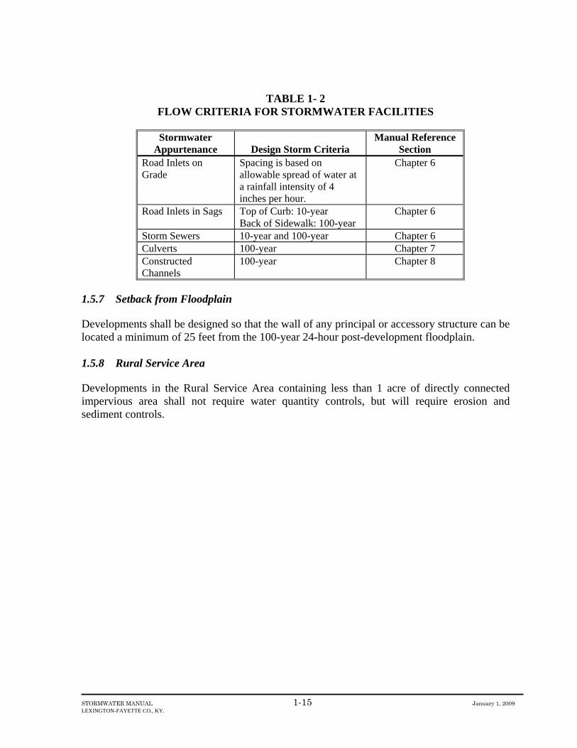
1.5.4 Downstream Study Limits Stormwater facilities for future development shall be designed so that the capacity of the existing and proposed pipes, culverts, channels, and other components of the drainage system are not exceeded. The study limits for a proposed development site shall extend downstream to a point where the drainage area is 10 times the area of the proposed development. The Engineer shall determine the existing flow capacity of the downstream drainage system impacted by the proposed development if the LFUCG has not conducted such a study. Table 1-2 lists the flow criteria for these drainage system components. 1.5.5 Capacity of the Proposed Drainage System Storm sewers, inlets, culverts, and constructed channels shall be designed to meet the design criteria in Table 1-2. 1.5.6 Flood Protection Elevation All residential, commercial, and industrial structures shall be constructed at or above the Flood Protection Elevation. The Flood Protection Elevation (FPE) shall be determined by the Engineer and shall be all of the following
• two feet above the calculated 100-year-post development floodplain elevation, or two feet above the FEMA base flood (100-year) elevation, whichever is higher
• two feet above the 100-year storm elevation in constructed channels • two feet above the 100-year storm elevation at low points in streets if there is no
overflow channel • two feet above the 100-year, 24-hour storm elevation in detention ponds and wet
ponds • two feet above the embankment crest of detention ponds and wet ponds
STORMWATER MANUAL 1-15 January 1, 2009 LEXINGTON-FAYETTE CO., KY.
TABLE 1- 2 FLOW CRITERIA FOR STORMWATER FACILITIES
Stormwater
Appurtenance Design Storm Criteria Manual Reference
Section Road Inlets on Grade
Spacing is based on allowable spread of water at a rainfall intensity of 4 inches per hour.
Chapter 6
Road Inlets in Sags Top of Curb: 10-year Back of Sidewalk: 100-year
Chapter 6
Storm Sewers 10-year and 100-year Chapter 6 Culverts 100-year Chapter 7 Constructed Channels
100-year Chapter 8
1.5.7 Setback from Floodplain Developments shall be designed so that the wall of any principal or accessory structure can be located a minimum of 25 feet from the 100-year 24-hour post-development floodplain. 1.5.8 Rural Service Area Developments in the Rural Service Area containing less than 1 acre of directly connected impervious area shall not require water quantity controls, but will require erosion and sediment controls.

STORMWATER MANUAL 1-16 January 1, 2009 LEXINGTON-FAYETTE CO., KY.
1.6 Water Quality Criteria for New Development 1.6.1 Impairment of Uses The runoff from impervious surfaces created by new development can result in impacts to the water quality of Fayette County. Impairment to aquatic life may occur because of the loss of aquatic habitat caused by
• the destruction of riparian vegetation • decreases in the base flow during non-runoff periods • increases in stream bank erosion from higher stages caused by additional runoff
volume • bottom scour from higher velocities through culverts and other conveyance
mechanisms • increased toxicity from the increased chemical content • the nuisance growth of algae and other aquatic plants resulting from the nutrients in
runoff • decreased light penetration from suspended material • increases in the sediment deposited on the stream bottom
Impairment to secondary contact recreation uses may result from
• increases in bacteriological content due to small animal wastes • increases in the presence of petroleum products
Impairment to public water supply uses may result from the
• growth of algae and other nuisance aquatic plants resulting from the nutrients in runoff • increases in bacteriological content due to small animal wastes • increases in the presence of petroleum products • increases in suspended solids resulting in an increased cost of water treatment • decreases in reservoir water storage capacity resulting from sedimentation
1.6.2 Exemptions from Quality Controls Development sites that are part of a regional stormwater master plan are exempted from quality controls. Sites less than one acre are also exempted. Water quality BMPs are not required for sites with less than ten percent imperviousness. 1.6.3 Water Quality Volume Criteria The impact of the increase in the volume of water that becomes runoff rather than infiltration from a development site shall be mitigated through the capture, storage, and release of a volume of water proportional to the amount of impervious area. This volume is referred to as the water quality volume. The procedures for calculating the water quality volume are

STORMWATER MANUAL 1-17 January 1, 2009 LEXINGTON-FAYETTE CO., KY.
contained in Chapter 10. The water quality volume from development projects greater than 1 acre shall be treated using BMPs described in Chapter 10. The practice of discharging downspouts to grass provides an infiltration volume credit. The use of swales also provides an infiltration credit. These credits are calculated as described in Chapter 10 and can be used to satisfy a portion of the water quality volume. The remaining water quality volume shall be provided in one or more of the BMPs shown in Table 1-1. For commercial and industrial areas, at least fifty percent of the site shall be treated with bioretention or infiltration. The remaining area shall be treated using one of the options in Table 1-1. 1.6.4 Infiltration Credit for Floodplains Proposed developments that contain a floodplain shall receive an infiltration credit of 0.5 acre-feet/acre of floodplain. The credit can be used against the required water quality volume. 1.6.5 Culvert Outlet Velocity Criteria The design velocity at the culvert outlet shall be reduced to match the natural stream velocity in accordance with the BMPs in Chapter 11 and the design procedures in Chapter 7. 1.6.6 Erosion Controls Non-structural and structural erosion and sediment control BMPs shall be designed and constructed in accordance with an erosion and sediment control plan, as described in Chapter 11. 1.6.7 Rural Service Area Developments in the Rural Service Area containing less than 1 acre of directly connected impervious area shall not require any water quality BMPs, but will require erosion and sediment controls.

STORMWATER MANUAL 1-18 January 1, 2009 LEXINGTON-FAYETTE CO., KY.
1.7 Stormwater Standards for Redevelopment Projects 1.7.1 Objectives The objectives of these standards are to (1) demonstrate UCG compliance with federal stormwater quality regulations and (2) prevent causing new flooding problems. Constructing water quality best management practices (BMPs) on redevelopment sites is typically more difficult and more expensive than on new development sites. To encourage redevelopment, the water quality requirements for redevelopment are less stringent than those for new development. Whereas new development sites must treat 100% of the runoff to meet the water quality requirements in this manual, redevelopment sites must treat a maximum of 20% of the runoff. Redevelopment projects generally do not increase the impervious area; thus, water quantity BMPs are not required if the impervious area stays the same or is reduced. 1.7.2 Application The stormwater standards for redevelopment shall apply to preliminary development plans initially submitted to LFUCG on or after January 1, 2005. Stormwater standards for redevelopment shall apply to sites that previously contained structures or parking lots, where one acre or more of land (including buildings and parking lots) will be disturbed. Disturbance is defined as construction that exposes soil; it does not include remodeling or pavement surfacing. Proposed development of infill parcels that never contained buildings or parking lots shall be considered new development. Proposed development of parcels containing a residence where the land use is agricultural shall also be considered new development. 1.7.3 Water Quantity Criteria for Redevelopment Water quantity BMPs are not required if the impervious area is not increased. If the impervious area is increased less than 1 acre, water quantity BMPs are not required if the downstream drainage system (to a blue-line stream) has sufficient capacity to carry the 100-year 1-hour and 100-year 6-hour storms (this is intended to prevent the construction of small bathtub detention basins because they are usually ineffective). Sufficient capacity for a pipe system shall be defined as no overflows at inlets or manholes. Sufficient capacity for an open channel system shall be defined as a drainage easement wide enough to carry the flow. If a drainage easement does not exist, sufficient capacity shall be defined as an insignificant (<0.1’) rise in the water surface elevation for each storm. Where required, BMPs shall be implemented to reduce peak flows to January 1, 2004 conditions for the design storms in Chapter 5. A fee in lieu may be allowed as described in Section 1.8.

STORMWATER MANUAL 1-19 January 1, 2009 LEXINGTON-FAYETTE CO., KY.
1.7.4 Water Quality Criteria for Redevelopment The water quality criteria shall require a 20% reduction in the impervious area that has existed on the site (based on historical maps or other documentation provided by the developer), or implement stormwater quality BMPs for 20% of the site impervious area, or a combination thereof. A fee in lieu of constructing water quality BMPs may be allowed as described in Section 1.8. It is anticipated that sites less than five acres will pay the fee, and sites of 5 acres or more will construct on-site BMPs. 1.7.5 Erosion and Sediment Control Erosion and sediment control BMPs shall be installed as described in Chapter 11.

STORMWATER MANUAL 1-20 January 1, 2009 LEXINGTON-FAYETTE CO., KY.
1.8 Fee-In-Lieu for New Development and Redevelopment Development projects and redevelopment projects are required to control the effects of stormwater runoff, including water quantity and water quality, in accordance with this manual. LFUCG recognizes that constructing on-site best management practices (BMPs) may not be the most effective method for controlling stormwater runoff. Therefore, LFUCG has established a fee-in-lieu of constructing on-site BMPs in such a way to facilitate development and redevelopment, reduce costs for stormwater management, and avoid unnecessary delays for the developer. The fee-in-lieu program is described below: 1. Where water quantity or water quality BMPs are required by this manual, LFUCG may
allow the Developer to pay a fee instead of constructing on-site BMPs whenever the Director of the Division of Engineering (Director) determines that on-site BMPs are not the most effective method of controlling stormwater runoff. This includes, but is not limited to, the following situations:
a. The Director has reviewed studies and evaluations conducted by the developer and
determined that constructing on-site BMPs • will not effectively improve water quality • will not effectively reduce peak flows • is not feasible because of design constraints, such as the inability for a below
ground structure to drain by gravity
b. Existing downstream homes and businesses that experience structure flooding are being removed from the floodplain by the UCG.
c. Flood control or water quality control BMPs are being planned or implemented in the
watershed.
d. Drainage improvements such as storm sewer replacement or enlargement in the watershed are funded.
2. LFUCG will enter into an agreement with each developer participating in the fee-in-lieu
program. Funds collected will be placed in a government account to be used for government water quality projects within or benefiting the watershed from which the funds originated.
3. The Director shall establish the fee for water quantity based on studies and evaluations
conducted by the developer.
The fee shall not be applied to the following because water quantity BMPs are not required as explained in previous sections of this manual:
• new development residential sites less than 5 acres if the downstream drainage system
has the capacity to carry the 100-year storm

STORMWATER MANUAL 1-21 January 1, 2009 LEXINGTON-FAYETTE CO., KY.
• new development commercial sites less than 1 acre if the downstream drainage system has the capacity to carry the 100-year storm
• redevelopment sites that do not increase the impervious area • redevelopment sites that increase the impervious area less than 1 acre if the
downstream drainage system has the capacity to carry the 100-year storm 4. The fee for water quality shall be based on the table below.
Disturbed
Area (acres)
Fee-in-Lieu of Constructing On-Site Water Quality BMPs
New Development Redevelopment
Less than 1.00
Not applicable because water quality BMPs are not required for sites that disturb less than 1 acre
Not applicable because water quality BMPs are not required for sites that disturb less than 1 acre
1.01- 5.00
Determined by the Director based on the developer’s cost estimate for constructing BMPs to treat 100% of the impervious area, including land costs if applicable.
Determined by the Director based on the developer’s cost estimate for constructing BMPs to treat 20% of the impervious area, including land costs if applicable.
Greater than 5.00
Generally not applicable. On-site BMPs will typically be required.
Generally not applicable. On-site BMPs will typically be required
STORMWATER MANUAL 1-22 January 1, 2009 LEXINGTON-FAYETTE CO., KY.
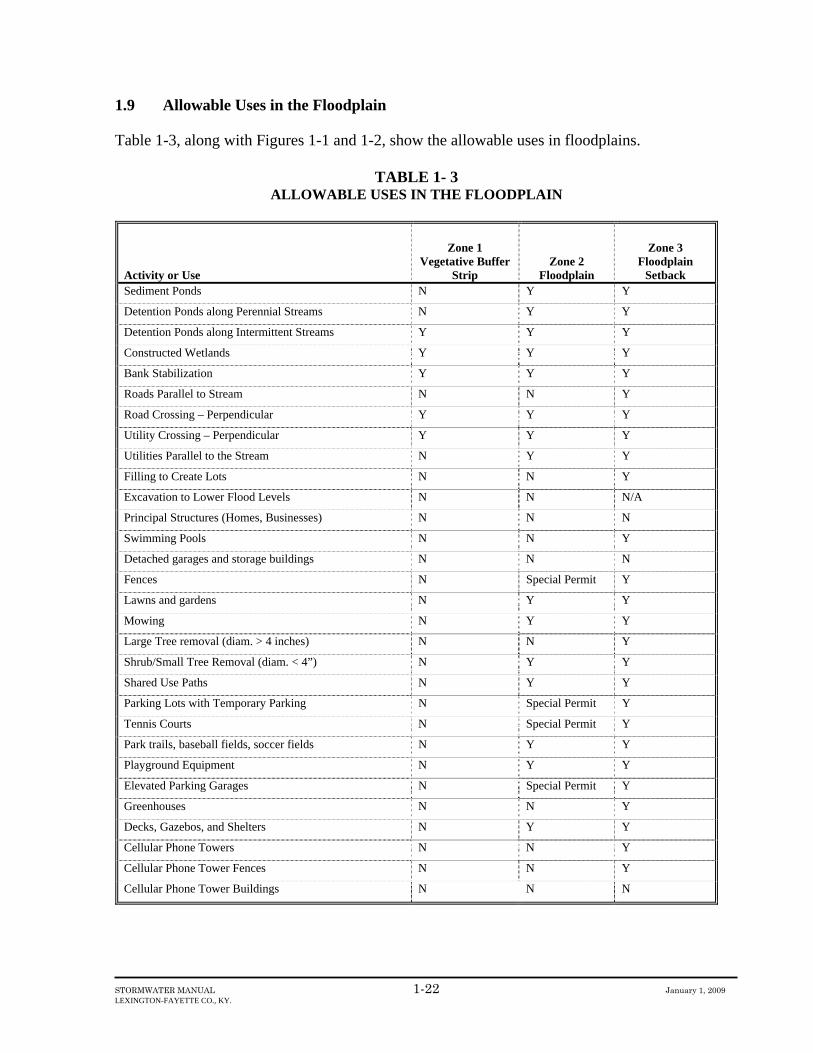
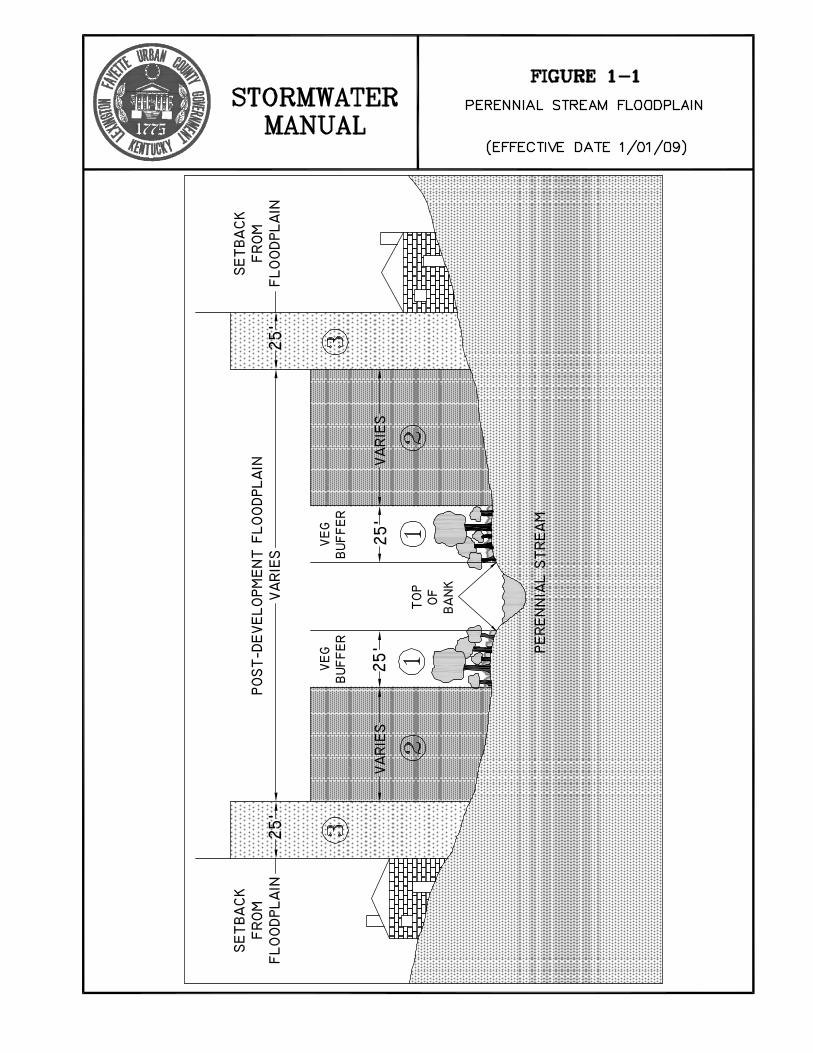
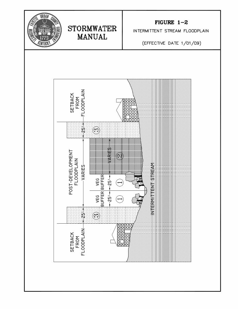
1.9 Allowable Uses in the Floodplain Table 1-3, along with Figures 1-1 and 1-2, show the allowable uses in floodplains.
TABLE 1- 3 ALLOWABLE USES IN THE FLOODPLAIN
Activity or Use
Zone 1 Vegetative Buffer
Strip Zone 2
Floodplain
Zone 3 Floodplain
Setback Sediment Ponds N Y Y
Detention Ponds along Perennial Streams N Y Y
Detention Ponds along Intermittent Streams Y Y Y
Constructed Wetlands Y Y Y
Bank Stabilization Y Y Y
Roads Parallel to Stream N N Y
Road Crossing – Perpendicular Y Y Y
Utility Crossing – Perpendicular Y Y Y
Utilities Parallel to the Stream N Y Y
Filling to Create Lots N N Y
Excavation to Lower Flood Levels N N N/A
Principal Structures (Homes, Businesses) N N N
Swimming Pools N N Y
Detached garages and storage buildings N N N
Fences N Special Permit Y
Lawns and gardens N Y Y
Mowing N Y Y
Large Tree removal (diam. > 4 inches) N N Y
Shrub/Small Tree Removal (diam. < 4”) N Y Y
Shared Use Paths N Y Y
Parking Lots with Temporary Parking N Special Permit Y
Tennis Courts N Special Permit Y
Park trails, baseball fields, soccer fields N Y Y
Playground Equipment N Y Y
Elevated Parking Garages N Special Permit Y
Greenhouses N N Y
Decks, Gazebos, and Shelters N Y Y
Cellular Phone Towers N N Y
Cellular Phone Tower Fences N N Y
Cellular Phone Tower Buildings N N N

CHAPTER 2
PERMITS
STORMWATER MANUAL 2-i August 29, 2011
LEXINGTON-FAYETTE CO., KY.
TABLE OF CONTENTS
2.1 Land Disturbance Permit ............................................................................................ 1
2.1.1 Purpose ................................................................................................................ 1
2.1.2 Procedure ............................................................................................................ 1
2.2 Kentucky Division of Water Floodplain Construction Permits ................................. 2
2.2.1 Purpose ................................................................................................................ 2
2.2.2 Procedure ............................................................................................................ 2
2.2.3 Determination of Need for Permit....................................................................... 2
2.2.4 Fills ...................................................................................................................... 4
2.3 Kentucky Division of Water KPDES Stormwater Permit .......................................... 5
2.3.1 Purpose ................................................................................................................ 5
2.3.2 Procedure ............................................................................................................ 5
2.4 Federal Emergency Management Agency (FEMA) ................................................... 6
2.4.1 Purpose ................................................................................................................ 6
2.4.2 Procedure ............................................................................................................ 6
2.4.3 Estimating Base Flood Elevations ...................................................................... 6
2.5 401 and 404 Permits – Kentucky Division of Water and U.S. Army Corps of
Engineers ................................................................................................................... 7
2.5.1 Purpose ................................................................................................................ 7
2.5.2 Procedure ............................................................................................................ 7

STORMWATER MANUAL 2-1 August 29, 2011
LEXINGTON-FAYETTE CO., KY.
2.1 Land Disturbance Permit
2.1.1 Purpose
A Land Disturbance Permit shall be obtained from the Division of Engineering in accordance
with Chapter 16, Article X, Division 5 of the LFUCG Code of Ordinances. Checklists and
other information can be found on the LFUCG stormwater webpage.
2.1.2 Procedure
See Chapter 11.
STORMWATER MANUAL 2-2 August 29, 2011
LEXINGTON-FAYETTE CO., KY.
2.2 Kentucky Division of Water Floodplain Construction Permits
2.2.1 Purpose
Pursuant to Kentucky law, dams or other improvements obstructing the movement of water
in the floodplain are often regulated by the Kentucky Division of Water (KDOW). The
purpose of the procedure described here is to comply with the provisions of Chapter 19 in the
Zoning Ordinance requiring that the KDOW first review obstructions to the flow of water in
floodplains. Implementation of the procedure should prevent a situation where the Urban
County Government would allow construction of and ultimately assume operation and
maintenance of a structure that did not meet the standards of the KDOW.
A Floodplain Construction Permit is required from the KDOW of the Environmental and
Public Protection Cabinet prior to the construction, reconstruction, relocation, or
improvement of any dam, embankment, levee, dike, bridge, fill, or other obstructions across
or along any stream or in the floodway of any stream. Permits are required for any such
activity in designated 100-year floodplains or areas known to be flood prone. Exemptions
may exist for activities in watersheds of less than one square mile of drainage. A permit
from the KDOW is also required to deposit or cause to be deposited any matter that will in
any way restrict or disturb the flow of water in the channel or in the floodway of any stream.
In addition, a KDOW permit is required prior to the construction of structures qualifying as
dams.
2.2.2 Procedure
In instances where KDOW permits are required, construction shall not begin until evidence
of the Floodplain Construction Permit, or a determination that no permit is required, is
provided to the Division of Engineering. In the case of dams, where water will be
impounded on a temporary basis, construction shall not begin on facilities dependent upon
the dam until an approval by the KDOW to impound water has been obtained. The
permitting requirements apply to dams constructed for sediment and erosion control,
stormwater detention, or just aesthetic amenities. The requirements also apply to other flow
obstructions like pump stations. The following procedure outlines the process for deciding
whether a KDOW permit is required.
2.2.3 Determination of Need for Permit
This section describes the process for determining whether a KDOW permit is required.
Step 1: Determine 100-year Post-Development Floodplain Boundaries
Post-development floodplain boundaries for the 100-year flood are defined in Chapter 1 of
this manual.
STORMWATER MANUAL 2-3 August 29, 2011
LEXINGTON-FAYETTE CO., KY.
If the analysis described in the definition of post-development floodplains indicates that the
construction is not in the floodplain, it can be submitted to the Division of Engineering as
evidence of compliance with KDOW procedures.
Step 2: Determine the Hazard Classification of the Obstruction per DOW Criteria
Hazard Classification A - This classification may be applied for structures located such that
failure would cause loss of the structure itself, but little or no additional damage to other
property. Such structures will generally be located in rural or agricultural areas where failure
may damage farm buildings other than residences, agricultural lands, or county roads.
Hazard Classification B - This classification may be applied for structures located such that
failure may cause significant damage to property and project operation, but loss of human life
is not envisioned. Such structures will generally be located in predominantly rural agricultural
areas where failures may damage isolated homes, main highways or major railroads, or cause
interruption of use or service of relatively important public utilities.
Hazard Classification C - This classification must be applied for structures located such that
failure may cause loss of life, or serious damage to homes, industrial or commercial buildings,
important public utilities, main highways or major railroads. This classification must be used if
failure would cause probable loss of human life.
The Division of Engineering methodology for characterizing the hazard is based on the height
of the structure. If the height is less than 15 feet, an A classification may be assumed if no
roadways, walkways, residences, commercial buildings, or agricultural buildings are located,
or could be located in the future, in the downstream floodplain within a distance from the
structure defined by the equation given below, unless visual analysis indicates that a higher
hazard classification is more appropriate.
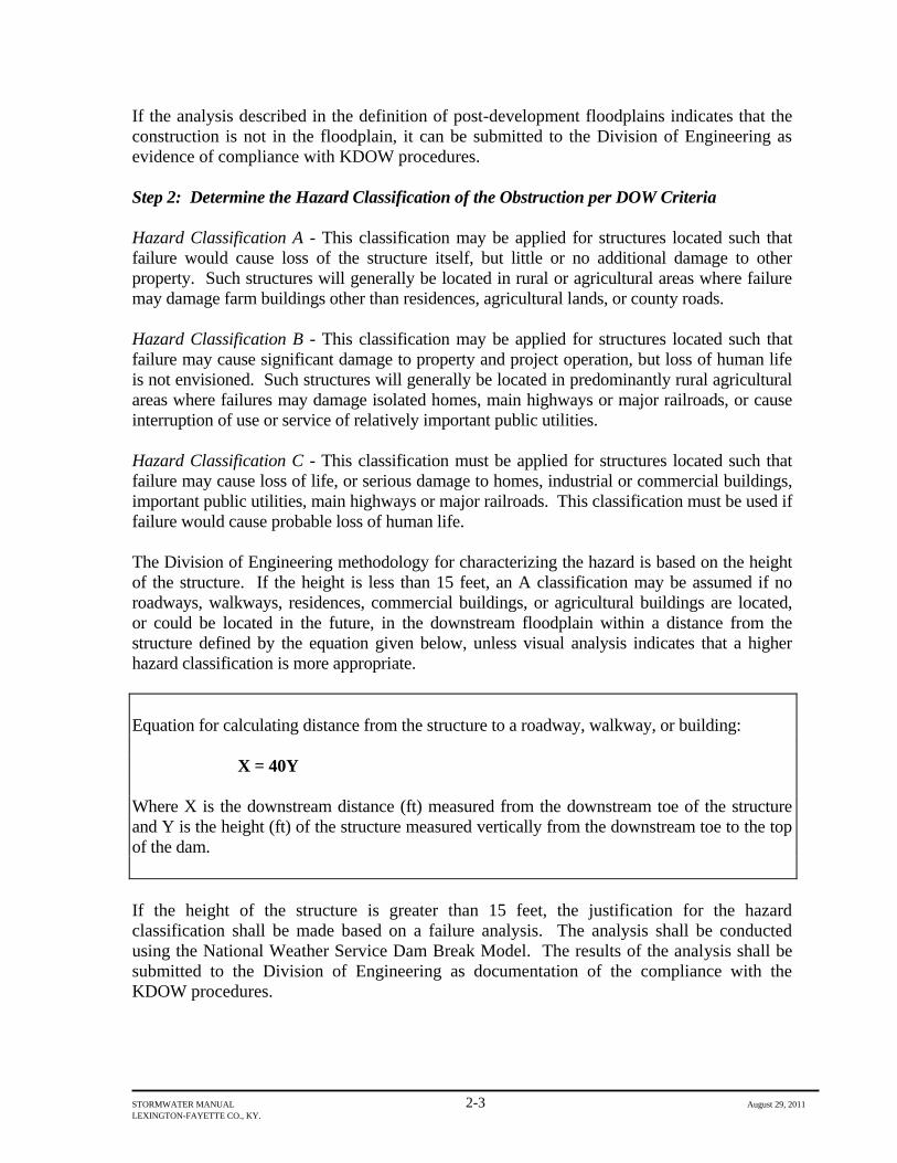
Equation for calculating distance from the structure to a roadway, walkway, or building:
X = 40Y
Where X is the downstream distance (ft) measured from the downstream toe of the structure
and Y is the height (ft) of the structure measured vertically from the downstream toe to the top
of the dam.
If the height of the structure is greater than 15 feet, the justification for the hazard
classification shall be made based on a failure analysis. The analysis shall be conducted
using the National Weather Service Dam Break Model. The results of the analysis shall be
submitted to the Division of Engineering as documentation of the compliance with the
KDOW procedures.

STORMWATER MANUAL 2-4 August 29, 2011
LEXINGTON-FAYETTE CO., KY.
Step 3: Determine if the Structure is a Dam
A structure is defined by the KDOW as a dam if the distance from the downstream toe to the
crest of the embankment is 25 feet or greater or if the structure has the potential for
impounding, either temporarily or permanently, 50 acre feet or more, measured to the crest of
the embankment.
A KDOW Permit is required if:
(1.) From step 3, the obstruction is a dam
(2.) From step 2, the hazard classification is a C
(3.) From step 2, the hazard classification is an A or B and the drainage area above the
obstruction is greater than 1 square mile
2.2.4 Fills
Fills not impounding water are a class of obstruction that are covered under this requirement.
A KDOW Floodplain Construction Permit is not required for a fill if the drainage area above
the fill is less than or equal to 1 square mile. However, in accordance with the requirements
given in Chapter 1 of this manual, fill may only be placed in the floodplain if the fill is
related to the construction of a stormwater management practice, roadway, or utility and the
fill does not cause an increase in the 100-year post development flood level as calculated
using the procedures given in Chapter 3 of this manual.
STORMWATER MANUAL 2-5 August 29, 2011
LEXINGTON-FAYETTE CO., KY.
2.3 Kentucky Division of Water KPDES Stormwater Permit
2.3.1 Purpose
Erosion and Sediment Control on construction sites of one acre or greater is controlled by the
Kentucky KPDES General Permit for Stormwater Point Sources (Construction). The
KPDES General Permit requires, among other things
1. the submission of a Notice of Intent to the Division of Water before construction
begins
2. the preparation of a stormwater best management practices plan, which includes
an erosion and sediment control plan, to be kept on-site at all times
3. a description of procedures to maintain erosion and sediment control measures
during the period of construction
4. the identification of each contractor or subcontractor who will install each erosion
and sediment control measure
5. the signing by each contractor or subcontractor of a statement certifying the
awareness of the requirements of the KPDES Stormwater Permit for the site
6. the inspection by qualified personnel, provided by the developer, of the site at
least once every seven calendar days and within 24 hours of the end of a storm of
0.5” or greater
7. the submission of a Notice of Termination to the Division of Water with a
statement certifying that all stormwater discharges associated with the
construction activity have been eliminated
2.3.2 Procedure
Construction shall not begin until the Notice of Intent and items 2.-5. above are provided to
the Division of Water with a copy to the Division of Engineering. During the construction
process, evidence of the inspection listed in item 6 above shall be submitted to the Division
of Water with a copy to the Division of Engineering.
STORMWATER MANUAL 2-6 August 29, 2011
LEXINGTON-FAYETTE CO., KY.
2.4 Federal Emergency Management Agency (FEMA)
2.4.1 Purpose
FEMA manages the National Flood Insurance Program (NFIP) based on maps showing
floodplains and flood hazard areas. As part of the agreement for making flood insurance
available in Fayette County, the NFIP required the LFUCG to adopt floodplain management
ordinances containing certain minimum requirements intended to reduce future flood losses.
LFUCG is also responsible for submitting data to FEMA reflecting revised flood hazard
information so that the NFIP maps can be revised as appropriate. Up to date maps allow risk
premium rates and floodplain management requirements to be based on current data.
In instances where construction in the floodplain changes the floodplain elevations or the
shape of the floodplain as shown on the NFIP maps, FEMA has a procedure for revising the
maps. In general, construction in floodplains is not envisioned in Fayette County except for
road and utility crossings and the construction of sanitary sewer and stormwater management
facilities. In some instances, construction of these facilities may change the floodplain
elevations, necessitating the filing of documents with FEMA to correct the floodplain maps.
In other instances, the FEMA maps may incorrectly show the floodplains. Where a
floodplain is shown incorrectly, the filing of documents with FEMA is required to correctly
define the floodplains.
2.4.2 Procedure
Construction activities within the FEMA floodplain shall comply with the requirements of
Article 19 of the Zoning Ordinance.
For projects that change the FEMA floodplain, the Engineer shall submit the appropriate
technical data to FEMA. The requirements for submitting the data can be obtained from the
LFUCG FEMA coordinator.
2.4.3 Estimating Base Flood Elevations
Areas designated as Zone A on Flood Insurance Rate Maps do not have Base Flood
Elevations (BFEs). It is acceptable to estimate the BFE by superimposing the Zone A limits
on a 2-foot contour map and interpolating between the contours.

STORMWATER MANUAL 2-7 August 29, 2011
LEXINGTON-FAYETTE CO., KY.
2.5 401 and 404 Permits – Kentucky Division of Water and U.S. Army Corps of
Engineers
2.5.1 Purpose
The KDOW Floodplain Construction Permit addressed above only relates to the potential
flooding from the construction of an obstruction to the flow of water in the stream or
floodplain. The KDOW has another permitting program (401 permit) related to construction
which impacts the stream channel and areas below the ordinary high water level. In general,
construction below the ordinary high water level is not envisioned in the waters of Fayette
County. However, if situations arise where construction is necessary below the ordinary high
water level or in wetlands, the Kentucky Division of Water (KDOW) has requirements for
projects that impact these waters. In addition, the U.S. Army Corps of Engineers (COE) has
requirements for projects that impact waters of the United States, including wetlands. Where
the KDOW 401 or COE 404 permits, including coverage under the COE Nationwide
Permits, are required, construction shall not begin until evidence of the 401 and/or 404
permits or a determination that no permit is required is provided to the LFUCG.
2.5.2 Procedure
Permit applications and related plans shall be submitted to the Corps of Engineers and
KDOW. Copies shall also be submitted to the LFUCG Division of Engineering.

CHAPTER 3 WATERSHED STUDIES
STORMWATER MANUAL 3-1 January 1, 2009 LEXINGTON-FAYETTE CO., KY.
3.1 Introduction Watershed studies shall be conducted to:
• determine the effects of a proposed development on the public drainage system • establish the post-development 100-year floodplain • identify existing drainage problems • identify potential locations for regional stormwater facilities that address both flood
control and water quality • establish design criteria over and above the design criteria specified elsewhere in this
manual to correct or improve existing drainage problems • develop a stormwater management plan for the watershed to minimize future
drainage problems and reduce existing problems
STORMWATER MANUAL 3-2 January 1, 2009 LEXINGTON-FAYETTE CO., KY.
3.2 Data Collection 3.2.1 Data Sources Appendix A lists numerous sources for obtaining mapping and other reference materials required as part of a watershed study. 3.2.2 Required Data The following data shall be collected: Watershed Characteristics Determine the size of the contributing drainage area, expressed in acres, from the following:
• 2’ contour maps with field checks to determine any significant changes in the contributing drainage area such as:
lakes sinkholes flood control structures grade changes which have occurred since preparation of the map
Watershed Land Use Document the existing and future land use. Information on existing land use can be obtained from:
• aerial photographs (conventional and infrared) • LFUCG zoning maps and the most current LFUCG Comprehensive Plan • USGS and other maps • landsat (satellite) images • soil maps
Existing land use data for small watersheds can best be determined or verified from a field survey. Use field surveys to update information on maps and aerial photographs, especially in basins that have experienced changes in development since the maps or photos were prepared. The Comprehensive Plan Land Use Map, Zoning Map, and the current Comprehensive Master Plan can be obtained from the LFUCG Division of Planning. Streams, Rivers, Ponds, Lakes, and Wetlands At all streams, rivers, ponds, lakes, and wetlands that will affect or may be affected by future development, collect the following data:
• boundary (perimeter) and elevation of the water surface • water elevation for design storms specified in this manual

STORMWATER MANUAL 3-3 January 1, 2009 LEXINGTON-FAYETTE CO., KY.
• detailed description of any natural or manmade spillway or outlet works including dimensions, elevations, material, and operational characteristics
• detailed description of any emergency spillway works including dimensions, materials, and elevations
• profile along top of any dam and a typical cross section of the dam • use of the water resource (stock water, aquatic habitat, recreation, power, irrigation,
municipal or industrial water supply, etc.) • riparian rights and/or ownership(s) • applicable water quality standards • existing data describing the physical, chemical, and biological water quality • identification of wetlands and sinkholes within the project boundaries or downstream
of project in a location which may be impacted by storm water runoff Roughness Coefficients Estimate roughness coefficients, in the form of Manning’s n values, for the entire flood limits of the stream within the reach to be evaluated. A tabulation of Manning’s n values with descriptions of their applications can be found in Chapter 8. Stream Profile Obtain streambed profile data to determine the average slope. Where there is a stream gage relatively close, obtain the discharge, with date and time of the reading corresponding to the stream level. Stream Cross-Sections Obtain stream cross-section data where stage-discharge-volume relationships will be necessary. Existing Structures
• Investigate any structures that may cause backwater or retard stream flow. • Evaluate the manner in which existing structures have been functioning with regard to
such things as scour, overtopping, damage, and debris. • For bridges, determine span lengths, height, type of piers, and substructure
orientation. • For culverts, determine the size, inlet and outlet geometry, slope, end treatment,
culvert material, and flow line profile. • Take photographs of high water debris lines. • Determine outlet structure (principal and emergency spillway) dimensions, material,
inlet condition, headwater and backwater conditions, slope, and invert elevations. • Determine an elevation profile along the top of the embankment for simple outlet
structures. • For water quality calculations, determine the storage volume below permanent pools. • Identify local sources of contamination, such as livestock, siltation, junk piles, and
other point sources. • Make a record of the condition of the structure concerning erosion, degradation, and
damage. • Take photographs of all structures to document their overall and detailed condition.

STORMWATER MANUAL 3-4 January 1, 2009 LEXINGTON-FAYETTE CO., KY.
• Inventory the sinkholes and their condition, and identify any sources of obstruction or local contamination. Take photographs to document the conditions of the sinkholes.
Acceptable Flood Levels Determine the lowest opening elevation of structures where flooding is known to occur. Flood History Evaluate the history of past floods and their effect on existing structures. Information may be obtained from newspaper accounts, local residents, flood marks, or other evidence of the height of historical floods. Obtain recorded flood data from the following agencies:
• U.S. Army Corps of Engineers • U.S.G.S. • Kentucky Division of Water • LFUCG
3.2.3 Documentation Document the field review with dated field notes and photographs initialed by the reviewer. Include the documentation with the project plans and calculations submitted to LFUCG. Collect field data in accordance with GIS requirements of the LFUCG. An example field inventory form is contained in Appendix B.
STORMWATER MANUAL 3-5 January 1, 2009 LEXINGTON-FAYETTE CO., KY.
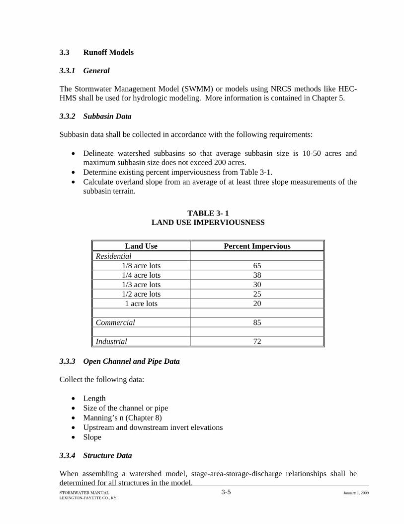
3.3 Runoff Models 3.3.1 General The Stormwater Management Model (SWMM) or models using NRCS methods like HEC-HMS shall be used for hydrologic modeling. More information is contained in Chapter 5. 3.3.2 Subbasin Data Subbasin data shall be collected in accordance with the following requirements:
• Delineate watershed subbasins so that average subbasin size is 10-50 acres and maximum subbasin size does not exceed 200 acres.
• Determine existing percent imperviousness from Table 3-1. • Calculate overland slope from an average of at least three slope measurements of the
subbasin terrain.
TABLE 3- 1 LAND USE IMPERVIOUSNESS
Land Use Percent Impervious
Residential 1/8 acre lots 65 1/4 acre lots 38 1/3 acre lots 30 1/2 acre lots 25 1 acre lots 20
Commercial 85 Industrial 72
3.3.3 Open Channel and Pipe Data Collect the following data:
• Length • Size of the channel or pipe • Manning’s n (Chapter 8) • Upstream and downstream invert elevations • Slope
3.3.4 Structure Data When assembling a watershed model, stage-area-storage-discharge relationships shall be determined for all structures in the model.

STORMWATER MANUAL 3-6 January 1, 2009 LEXINGTON-FAYETTE CO., KY.
• Calculate the stage-discharge curve for each structure. • Using the 2-foot contour lines and field information, calculate a stage-area-storage
relationship for each structure in the model. Include storage below the permanent pools. The stage-area information will allow the model to account for evaporation during continuous simulation.
• Combine the stage-discharge curve with the stage-area-storage curve to make one table for input into the model.
3.3.5 Error Analysis When all the data is entered, run the model and check for errors in the run. Look for mass balance problems, model connectivity, correct data input, and proper model execution. 3.3.6 Calibration The model should be calibrated against historic stream flow data if available.

STORMWATER MANUAL 3-7 January 1, 2009 LEXINGTON-FAYETTE CO., KY.
3.4 Post-Development Floodplain Analysis 3.4.1 General Once the runoff model is complete, post-development floodplains shall be determined with the United States Army Corps of Engineers’ HEC-RAS computer program. This program will also provide results to indicate roadway and structure flooding. The design storm for floodplain analysis is contained in Chapter 5. This portion of the chapter details how to build the HEC-RAS input file for a watershed study. 3.4.2 Post-Development Floodplain Definition The post-development floodplain shall be determined for streams shown as waters on Fayette County GIS waters coverage. The post-development watershed condition shall be based on future land use. 3.4.3 Cross-Sections HEC-RAS determines floodplains based on cross-section data provided by the user. The following methodology shall be employed when developing cross-sections.
• Starting at the most downstream end of the study area, locate a cross-section at least every 200 feet until the upstream end of the study area is reached.
• Orient the cross section so that it is perpendicular to the contour lines. • Using a 2’ contour map, determine stations and elevations along each cross-section. • Determine the station along the left side and the station along the right side of each
cross-section that corresponds to the top of bank. • Determine the downstream reach length from each cross-section to the preceding
cross-section along the left bank, centerline, and right bank. The data outlined above are required for each cross-section. If a cross-section happens to fall where a tributary intersects the channel, then employ one of the following two options.
• Delete the tributary-impacted cross-section from the analysis. • Copy the stations and elevations from the downstream cross-section to the tributary-
impacted cross-section, but increase all the elevations along the tributary-impacted cross-section by the difference in elevation of the centerline of the two cross-sections.
If tributaries are to be modeled, treat them similarly to the main stream by working from downstream to upstream and spacing cross-sections at 200’ intervals. 3.4.4 Roughness Values and Coefficients Working from downstream to upstream, specify the following roughness values and coefficients:
• left bank = Manning’s n from Chapter 8

STORMWATER MANUAL 3-8 January 1, 2009 LEXINGTON-FAYETTE CO., KY.
• right bank = Manning’s n from Chapter 8 • stream channel = Manning’s n from Chapter 8 • contraction coefficient = 0.10 • expansion coefficient = 0.30
If the entire stream reach has the same set of roughness values from downstream to upstream, then only specify these values at the beginning of the input file. 3.4.5 Flow and Water Surface Elevations The results from SWMM or HEC-HMS will provide the flows and water surface elevations at flow control structures for each HEC-HMS run. 3.4.6 Rounding of Water Surface Elevations The water surface elevations from HEC-RAS shall be rounded to the nearest 0.1’.

APPENDIX 3-A – SOURCES OF DATA

STORMWATER MANUAL 3-A-1 January 1, 2009 LEXINGTON-FAYETTE CO., KY.
• Flood Plain Delineations and Studies Federal Emergency Management Agency Flood Map Distribution Center 6930 (A-F) San Tomas Road Baltimore, Maryland 21227-6227 www.fema.gov/msc/femahome.htm
Lexington-Fayette Urban County Government Division of Engineering 200 E. Main Street Lexington, Kentucky 40507 (859) 258-3410 Kentucky Department for Environmental Protection Division of Water 14 Reilly Road Frankfort, Kentucky 40601 (502) 564-3410
• Hydraulic Studies Kentucky Transportation Cabinet
Department of Highways State Office Building Frankfort, Kentucky 40601 (502) 564-4890
Lexington-Fayette Urban County Government Division of Engineering 200 E. Main Street Lexington, Kentucky 40507 (859) 258-3410 U.S. Army Corps of Engineers
Louisville District P.O. Box 59 Louisville, Kentucky 40201
(502) 582-5601 Kentucky Department for Environmental Protection Division of Water 14 Reilly Road Frankfort, Kentucky 40601 (502) 564-3410
• Meteorological Data Midwestern Climate Center 2204 Griffith Drive Champaign, Illinois 61820-7493 (217) 244-8226 mcc.sws.uiuc.edu

STORMWATER MANUAL 3-A-2 January 1, 2009 LEXINGTON-FAYETTE CO., KY.
National Oceanography and Atmospheric Agency (NOAA) Climate Data Center Ashville, North Carolina 28801 www.crh.noaa.gov/lmk/climate.htm U.S. Geological Survey, Water Resources Division 9818 Bluegrass Parkway Louisville, Kentucky 40299-1906 (502) 493-1900 www.usgs.gov/public/data.html
• Water Quality Data Kentucky Department for Environmental Protection
Division of Water 14 Reilly Road Frankfort, Kentucky 40601 (502) 564-3410
U.S. Geological Survey, Water Resources Division 9818 Bluegrass Parkway Louisville, Kentucky 40299-1906 (502) 493-1900 www.usgs.gov/public/data.html Lexington-Fayette Urban County Government Division of Engineering 200 E. Main Street Lexington, Kentucky 40507 (859) 258-3410

APPENDIX 3- B – EXAMPLE FIELD INVENTORY FORM

Pond/Culvert Inventory Data Sheet
STORMWATER MANUAL 3-B-1 January 1, 2009 LEXINGTON-FAYETTE CO., KY.
Pond/Culvert ID: _________ Wet or Dry Location: _____________________ Purpose of Structure: Sediment/Retention Farm pond Road crossing Usage of Structure: Crew: Date: Project: Roll # Picture # Photograph Description _____ ______ Upstream looking at dam _____ ______ Inlet _____ ______ Outlet _____ ______ Emergency spillway (if applicable)
Physical Data Dominant ground surface in water storage area: Bare soil Riprap Light vegetation Concrete Dense vegetation Length to Width Ratio: 0.5-1 1-1 2-1 > 2-1 SKETCH approximate geometry on back.
Structure Data Impoundment: Earthen Concrete Natural Basin Other ______ Outlet Condition: Little or no erosion Fairly eroded Severely eroded
Damaged Debris Present Inlet Condition: Little or no erosion Fairly eroded Severely eroded
Damaged Debris Present Signs of Water Flowing Over Dam: Yes No Describe: Primary Inlet Type Size (in.) # Outlets Material Circular Pipe _______ _______ Concrete Box Culvert _______ _______ Metal Instream Weir _______ _______ PVC Hor. Elliptical Pipe _______ _______ Other _________ Vert. Elliptical Pipe _______ _______ Manning’s n Other _____________ _______ _______ _______ Primary Outlet Type Size (in.) # Outlets Material Circular Pipe _______ _______ Concrete Box Culvert _______ _______ Metal Instream Weir _______ _______ PVC Hor. Elliptical Pipe _______ _______ Other _________ Vert. Elliptical Pipe _______ _______ Manning’s n Other _____________ _______ _______ _______ Emergency Spillway Dimensions (if applicable) Depth: _____ in. Material: Riprap Concrete Width: _____ in. Vegetation Other _________ Additional Comments: (ex: livestock access to stream/pond; silt present in culvert, etc.) Survey required? Yes No

CHAPTER 4 DESIGN DOCUMENTATION

STORMWATER MANUAL 4-1 January 1, 2009 LEXINGTON-FAYETTE CO., KY.
4.1 Overview 4.1.1 Introduction An important part of the design or analysis of any hydraulic facility is the documentation. Appropriate documentation is essential because of:
• the importance of public safety • future reference by engineers (when improvements, changes, or rehabilitations are
made to the drainage facilities) • information leading to the development of defense in matters of litigation • public information
Frequently, it is necessary to refer to plans, specifications and analysis long after the actual construction has been completed. Documentation permits evaluation of the performance as anticipated or to establish the cause of unexpected behavior, if such is the case. In the event of a failure, it is essential that contributing factors be identified in order that recurring damage can be avoided. 4.1.2 Definition The definition of hydrologic and hydraulic documentation as used in this chapter is the compilation and preservation of the design and related details as well as all pertinent information on which the design and decisions were based. This includes maps, field survey information, source references, photographs, engineering calculations and analyses, measured and other data, and flood history including narratives from newspapers and individuals such as highway maintenance personnel and local residents who witnessed or had knowledge of an unusual event.

STORMWATER MANUAL 4-2 January 1, 2009 LEXINGTON-FAYETTE CO., KY.
4.2 Purpose The purpose of this chapter is to present the documentation that will be included in the design files and on the construction plans. This chapter focuses on the documentation of the findings obtained in using the other chapters of this manual, and thus engineers should be familiar with the hydrologic and hydraulic design procedures associated with this manual. This chapter identifies LFUCG’s system for organizing the documentation of hydraulic designs and reviews so as to provide as complete a history of the design process as is practical. The major purpose of providing good documentation is to define the design procedure that was used and decisions that were made to arrive at the final design. Documentation should be viewed as the record of reasonable and prudent design analysis based on the best available technology. Thus, good documentation can provide the following:
• identification of the situation at the time of design which might be very important if legal action occurs in the future
• protection for the engineer by proving that reasonable and prudent actions were, in fact, taken (such proof should certainly not increase a potential court award and may decrease it by disproving claims of negligence by the plaintiff)
• documentation that generally accepted procedures and analysis were used at the time of the design which were commensurate with the perceived site complexity and flood hazard (this should further disprove negligence claims)
• a continuous site history to facilitate future reconstruction • the file data necessary to quickly evaluate future site problems that might occur
during the facility’s service life • expedited plan development by clearly providing the reasons and rationale for
specific design decisions

STORMWATER MANUAL 4-3 January 1, 2009 LEXINGTON-FAYETTE CO., KY.
4.3 Improvement Plans 4.3.1 50 Percent Design The following information shall be submitted on a 2’ contour map at a scale of 1”=50’. The drawing size shall be 24” x 36”.
• a map showing all drainage areas and subareas used to size hydraulic structures • proposed inlet, storm sewer, culvert, and manhole system and their sizing calculations • proposed stormwater best management practices • proposed constructed channels and their sizing calculations • 10-year and 100-year post development floodplains • FEMA floodplain • sinkholes • caves • springs • ponds • streams • wetlands • tree stands • steep slopes greater than 15% • greenways shown in the Greenway Master Plan • existing and proposed underground utilities • the sinkhole surface drainage analysis as described in the Subdivision Regulations
4.3.2 Final Design Final design drawings shall be 24 x 36” in size. Plan view drawings shall be at a scale of 1”=50’ with 2’ contours. Profile sheets shall be at a scale of 1”=50’ horizontal and 1”=5’ vertical. Hydrology Submit the following items:
• watershed area size • peak discharge and hydrographs for design storms • expected level of development in upstream watershed over the anticipated life of the
facility (include sources of basis for these development projections)
Inlets, Storm Sewers, and Manholes Submit the following items:
• computations for inlets and pipes, including hydraulic grade lines • complete drainage area map • a schematic indicating storm drain system layout

STORMWATER MANUAL 4-4 January 1, 2009 LEXINGTON-FAYETTE CO., KY.
• pipe lengths, slopes, diameters, and material • structure types, labels • grate elevations • existing and proposed 2’ contours • separate sheets for details
Plan View:
• street layout, lot lines • catch basins: type, designation (station and number), invert elevation, and station
offset • pipes: sizes, type, class, slope, and designation • manholes: size and type, station and offset • headwalls: type and invert elevation • sanitary sewer crossings • culvert size and shape • other utility line crossings
Profile View:
• underground utility crossings • existing and proposed ground surfaces • curb inlets: elevations and type • manholes: elevations and type • pipes with size, grade, type, class, length • headwall type and elevation • all crossings (with elevations) of sanitary sewers and underground utilities • all street sections at crossings and all regrade contours • capacity and proposed flows in pipes • hydraulic grade lines • manholes • inlet and outlet elevations of pipes • copies of all computer analyses, with input data listed and output clearly identified
Culverts and Bridges Submit the following items:
• culvert performance curves • allowable headwater elevation and basis for its selection • cross-section(s) used in the design highwater determinations • roughness coefficient assignments (n values) • observed highwater, dates, and discharges • stage discharge curves • performance curves showing the calculated backwater elevations and outlet velocities
for the design storms • type of culvert entrance condition

STORMWATER MANUAL 4-5 January 1, 2009 LEXINGTON-FAYETTE CO., KY.
• culvert outlet appurtenances and energy dissipation calculations and designs • copies of all computer analyses, with input data listed and output clearly identified • roadway geometry (plan and profile)
Constructed Channels Submit the following items:
• profiles • cross-section(s) used in the design water surface determinations and their locations • roughness coefficient assignments (n values) • channel velocities • water surface profiles through the reach for the design 100-year storm • design analysis of materials proposed for the channel bed and banks • energy dissipation calculations and designs • copies of all computer analyses, with input data listed and output clearly identified
Stormwater Best Management Practices Submit the following items:
• design calculations and schematics • complete drainage area map, delineating area draining to each practice and denoting
total area and impervious area draining to each device • separate detail sheet for detention/retention basins • detail sheets for water quality treatment devices • water quality treatment practice (designate type of device, total area and impervious
area draining to device, and volume used to size device) • embankment cross section • top of embankment elevation • peak stages • emergency spillway details • principal spillway details • 1’-contour plan view of detention volume • other utilities
Erosion and Sediment Control Plan Submit the Erosion and Sediment Control Plan described in Chapter 11. 4.3.3 Composite Drainage Plan This plan is intended to aid homebuilders and commercial/industrial builders in preparing their application for a building permit. The following information shall be shown on the Composite Drainage Plan.
• surface drainage easements on each lot

STORMWATER MANUAL 4-6 January 1, 2009 LEXINGTON-FAYETTE CO., KY.
• flow arrows that indicate the direction of surface drainage through each surface drainage easement
• sanitary sewers and manholes • storm sewers and manholes • surface inlets, curb inlets, constructed channels, and stormwater best management
practices • Flood Protection Elevation for
Lots adjacent to or containing a post-development floodplain Lots adjacent to or containing a constructed channel Lots at the low point of a street Lots adjacent to a detention/retention pond
• Environmentally sensitive areas • Non-buildable areas such as sinkholes, floodplains, vegetation buffer strips, and
wetlands • Alluvial soils

STORMWATER MANUAL 4-7 January 1, 2009 LEXINGTON-FAYETTE CO., KY.
4.4 Record Drawings A record drawing of all stormwater structures shall be submitted at the end of construction. Plan view drawings shall be at a scale of 1”=50’ with 2’ contours. Profile sheets shall be at a scale of 1”=50’ horizontal and 1”=5’ vertical. Drawings shall be 24” x 36” in size.

CHAPTER 5 HYDROLOGY
STORMWATER MANUAL 5-1 January 1, 2009 LEXINGTON-FAYETTE CO., KY.
5.1 Introduction 5.1.1 Purpose The analysis of the peak flow, volume of runoff, and time distribution of flow is fundamental to the design of storm water drainage facilities. Errors in the estimates can result in a structure that is either undersized and causes drainage problems or oversized and costs more than necessary. On the other hand, it must be realized that any hydrologic analysis is only an approximation. The relationship between the amount of precipitation on a drainage basin and the amount of runoff from the basin is complex, and too little data are available on the factors influencing the rural and urban rainfall-runoff relationship to expect exact solutions. The purpose of this chapter is to describe approved methods of hydrological analysis for watershed studies and for the design of sediment ponds, stormwater best management practices, inlets, storm sewers, culverts, and channels. 5.1.2 Continuous Simulation as the Standard LFUCG’s approach is to manage both water quantity and water quality in a manner consistent with the development of new, more scientific techniques that take advantage of the computing power now available through the use of personal computers. The available computing power allows the use of continuous simulation models using actual historical rainfall events rather than the synthetic single-event storms currently used. This chapter describes both currently approved single event models and continuous simulation models. The single event models can be used on an interim basis as the LFUCG moves toward the exclusive use of continuous simulation models.

STORMWATER MANUAL 5-2 January 1, 2009 LEXINGTON-FAYETTE CO., KY.
5.2 Approved Methods 5.2.1 Single Event Modeling Two models are approved for single event hydrologic modeling. They are the Corps of Engineers HEC-HMS program and the U.S. Environmental Protection Agency’s Stormwater Management Model (SWMM). More information is given later on these models. Other computer programs may be used for designing storm sewers, open channels, culverts, inlets, and detention ponds if they use the methods in this chapter for determining runoff hydrographs and peak flows. 5.2.2 Continuous Simulation SWMM shall be the model used when conducting continuous simulations. The LFUCG will provide the Lexington rainfall record for use in such a simulation. 5.2.3 Rational Method The Rational Method may be used to compute peak flows for drainage areas less than or equal to 25 acres when designing inlets, storm sewers, culverts, and channels.

STORMWATER MANUAL 5-3 January 1, 2009 LEXINGTON-FAYETTE CO., KY.
5.3 Design Rainfall Event 5.3.1 Single Event Modeling Stormwater facilities shall be designed using the design storms in Table 5-1. The design storm distributions are contained in Appendix 5A. 5.3.2 Continuous Simulation The LFUCG will provide the rainfall record for continuous simulation.
TABLE 5- 1 APPLICATION OF DESIGN STORMS
Design Storm Stormwater Facility
Floodplains Detention Ponds1
Inlets Storm Sewers
Culverts Constructed Channels
Sediment Ponds4
1-year 1-hour • 2 10-year 1-hour • • 10-year 6-hour • • •10-year 24-hour •100-year 1-hour • • • 3 • 100-year 6-hour • •100-year 24-hour • • • 3 June 18, 1992 • June 26, 1995 •
1. Detention ponds shall be designed to reduce post-development peak
flows to pre-development peak flows for the 10-year 6-hour, 100-year 6-hour, June 18, 1992, and June 26, 1995 storms. The emergency spillway shall be designed to pass the 100-year 24-hour storm.
2. Constructed channels in back yards and side yards of residential areas
shall be designed with a paved trickle channel. The trickle channel shall be designed to carry 50% of the 1-year 1-hour storm.
3. The storm producing the largest peak flow shall be used to design
culverts.
4. Sediment ponds shall be designed to: • remove 80% of total suspended solids for the 10-year 24-hour
storm (or achieve a detention time of 24-48 hours) • reduce peak flows to pre-development levels for the 10-year 6-hour
and 100-year 6-hour storms

STORMWATER MANUAL 5-4 January 1, 2009 LEXINGTON-FAYETTE CO., KY.
5.4 HEC-HMS Model 5.4.1 Input Parameters Runoff Volume
• The Green-Ampt method or Curve Number method may be used to determine the runoff volume.
• Green-Ampt soil parameters are shown in Table 5-2 for each soil group listed in the NRCS Soil Survey for Fayette County.
• Curve Numbers are based on the type of land use. Typical values are given in
Table 5-3. Unit Hydrograph
• The NRCS Unit Hydrograph Method shall be used. The time of concentration shall be determined using the method described in Technical Release No. 55 published by the U.S. Department of Agriculture, Natural Resources Conservation Service.
Storage Routing
• Use the stage-discharge-volume relationship for the structure.
Watershed Delineation
• Watersheds shall be subdivided into areas with homogenous land use. The subwatersheds shall have an average size of 10-50 acres, and a maximum size of 200 acres.

STORMWATER MANUAL 5-5 January 1, 2009 LEXINGTON-FAYETTE CO., KY.
TABLE 5- 2 GREEN-AMPT INFILTRATION PARAMETERS
FOR FAYETTE COUNTY SOILS
NRCS Soil Series NRCS Hydrologic Soil Group
Saturated Hydraulic Conductivity
(inches/hour)
Wetting Front Suction (inches)
Initial Moisture Deficit (in/in)
Armour B 0.20 6.6 0.17
Braxton C 0.10 8.6 0.14
Captina C 0.10 8.6 0.14
Culleoka B 0.20 6.6 0.17
Donerail C 0.10 8.6 0.14
Egam C 0.10 8.6 0.14
Fairmount D 0.03 12.5 0.08
Huntington B 0.20 6.6 0.17
Lanton D 0.03 12.5 0.08
Lawrence C 0.10 8.6 0.14
Lindside C 0.10 8.6 0.14
Loradale C 0.10 8.6 0.14
Loudon C 0.10 8.6 0.14
Lowell C 0.10 8.6 0.14
Maury B 0.20 6.6 0.17
McAfee C 0.10 8.6 0.14
Melvin D 0.03 12.5 0.08
Mercer C 0.10 8.6 0.14
Newark C 0.10 8.6 0.14
Russellville C 0.10 8.6 0.14
Salvisa C 0.10 8.6 0.14
For areas where there is no detailed NRCS soil survey, use the following values:
• Saturated Hydraulic Conductivity – 0.15 • Wetting Front Suction – 7.6 • Initial Moisture Deficit – 0.155

STORMWATER MANUAL 5-6 January 1, 2009 LEXINGTON-FAYETTE CO., KY.
TABLE 5- 3 CURVE NUMBERS
Land Use
Percent
ImperviousHydrologic Soil Group
A B C D Urban Areas
Parking Lots, Roofs, Driveways, and Streets
100 98 98 98 98
Commercial Development
85 89 92 94 95
Industrial Development
72 81 88 91 93
Residential Development:
1/8 acre lots or less
65 77 85 90 92
1/4 acre lots
38 61 75 83 87
1/3 acre lots
30 57 72 81 86
1/2 acre lots
25 54 70 80 85
1 acre lots 20 51 68 79 84
Pervious Areas
Lawns, Parks, Golf Courses, Cemeteries, etc.
- 39 61 74 80
Pasture for Grazing (not mowed)
- 39 61 74 80
Meadows (mowed for hay)
- 30 58 71 78
Brushy Areas
- 30 48 65 73
Woods
- 30 55 70 77
1. For urban areas that have a different percent impervious than those shown above,
calculate a composite Curve Number using a Curve Number of 98 for impervious areas and the associated Curve Number for the pervious area from the table above.
2. For areas where there is no detailed NRCS Soil Survey, assume the subwatershed
is 50% Group B soils and 50% Group C soils.

STORMWATER MANUAL 5-7 January 1, 2009 LEXINGTON-FAYETTE CO., KY.
5.5 Stormwater Management Model (SWMM) 5.5.1 Input Parameters Infiltration
• Green-Ampt soil parameters are shown in Table 5-2 for each soil group listed in the NRCS Soil Survey.
Overland Flow
• Use the values in Table 5-4 for N.
Depression Storage
• Impervious depression storage = 0.02 inches • Pervious depression storage = 0.10 inches
Monthly Evaporation
• Use the values in Table 5-5.
Storage Routing
• Use the stage-discharge-volume relationship for the structure.
Watershed Delineation
• Watersheds shall be subdivided into areas with homogenous land use. The subwatersheds shall have an average size of 10-50 acres, and a maximum size of 200 acres.

STORMWATER MANUAL 5-8 January 1, 2009 LEXINGTON-FAYETTE CO., KY.
5.5.2 Subwatershed Width Calculation The following method shall be used to calculate the subwatershed width:
Subwatershed Boundary
A1
A2L
Subwatershed Width = W = (2 - Sk) x L Where Sk = skew factor (0<Sk<1) = (A2 - A1)/(A1 + A2) A1 = Area on one side of the channel A2 = Area on the other side of the channel L = Length of the channel

STORMWATER MANUAL 5-9 January 1, 2009 LEXINGTON-FAYETTE CO., KY.
TABLE 5- 4 MANNINGS N FOR OVERLAND FLOW
Surface N
Asphalt or Concrete 0.015 Gravelled Surface 0.02 Short Grass Pasture 0.15 Dense Shrubbery and Forest Litter 0.40 Heavily Wooded 0.40 Bluegrass Sod 0.45
TABLE 5- 5 MONTHLY EVAPORATION RATES FOR FAYETTE COUNTY
Month Inches / Month January 1.31 February 1.52
March 2.97 April 3.83 May 5.23 June 6.71 July 6.96
August 6.62 September 4.97
October 3.55 November 2.14 December 1.39

STORMWATER MANUAL 5-10 January 1, 2009 LEXINGTON-FAYETTE CO., KY.
5.6 Rational Method The following equation may be used for drainage areas less than or equal to 25 acres. Q = CIA where:
Q = peak flow in cubic feet per second C = 0.95 for impervious areas 0.20 for pervious areas A = drainage area I = rainfall intensity
The rainfall intensity shall be determined based on Table 5-6:
TABLE 5- 6 TIME OF CONCENTRATION VERSUS RAINFALL INTENSITY
Time of Concentration
(minutes) Intensity
(inches/hour) 1 yr. 10 yr. 100 yr.
10 3.2 5.3 6.9 15 2.8 4.4 5.7 30 1.9 3.1 4.2 60 1.2 2.0 2.9
The time of concentration shall be determined using the method described in Technical Release No. 55 published by the U.S. Department of Agriculture, Natural Resources Conservation Service. The minimum time of concentration shall be 10 minutes.

APPENDIX 5 A DESIGN STORM DISTRIBUTIONS
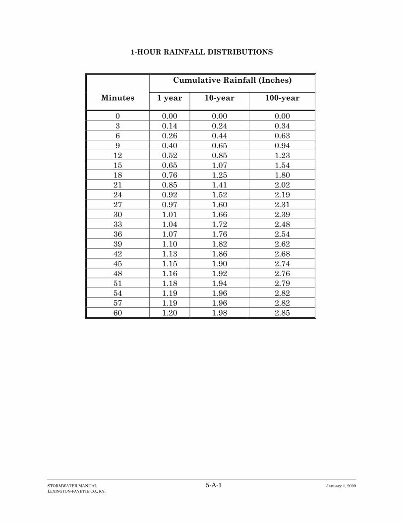
STORMWATER MANUAL 5-A-1 January 1, 2009 LEXINGTON-FAYETTE CO., KY.
1-HOUR RAINFALL DISTRIBUTIONS
Cumulative Rainfall (Inches)
Minutes 1 year 10-year 100-year
0 0.00 0.00 0.00 3 0.14 0.24 0.34 6 0.26 0.44 0.63 9 0.40 0.65 0.94 12 0.52 0.85 1.23 15 0.65 1.07 1.54 18 0.76 1.25 1.80 21 0.85 1.41 2.02 24 0.92 1.52 2.19 27 0.97 1.60 2.31 30 1.01 1.66 2.39 33 1.04 1.72 2.48 36 1.07 1.76 2.54 39 1.10 1.82 2.62 42 1.13 1.86 2.68 45 1.15 1.90 2.74 48 1.16 1.92 2.76 51 1.18 1.94 2.79 54 1.19 1.96 2.82 57 1.19 1.96 2.82 60 1.20 1.98 2.85
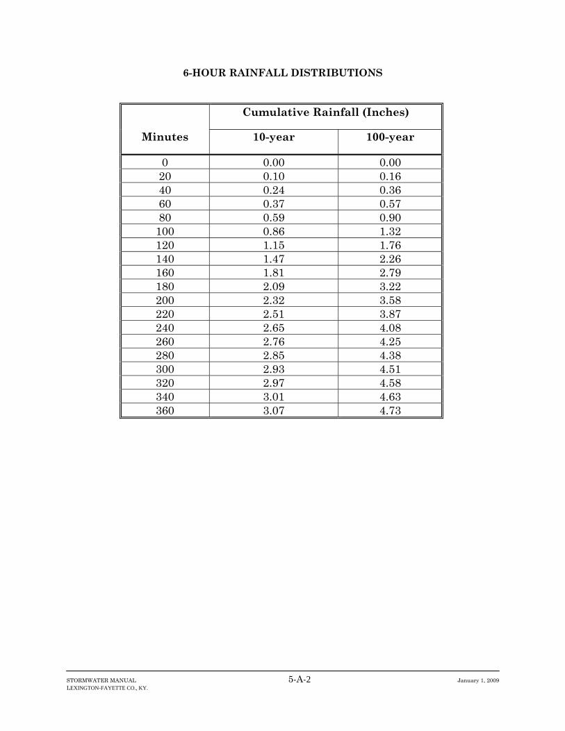
STORMWATER MANUAL 5-A-2 January 1, 2009 LEXINGTON-FAYETTE CO., KY.
6-HOUR RAINFALL DISTRIBUTIONS
Cumulative Rainfall (Inches)
Minutes 10-year 100-year
0 0.00 0.00 20 0.10 0.16 40 0.24 0.36 60 0.37 0.57 80 0.59 0.90
100 0.86 1.32 120 1.15 1.76 140 1.47 2.26 160 1.81 2.79 180 2.09 3.22 200 2.32 3.58 220 2.51 3.87 240 2.65 4.08 260 2.76 4.25 280 2.85 4.38 300 2.93 4.51 320 2.97 4.58 340 3.01 4.63 360 3.07 4.73

STORMWATER MANUAL 5-A-3 January 1, 2009 LEXINGTON-FAYETTE CO., KY.
10-YEAR – 24-HOUR RAINFALL DISTRIBUTION
Hours
10-year Cumulative Rainfall (Inches)
Hours
10-year Cumulative
Rainfall (Inches)0.0 0.00 12.5 3.21 0.5 0.02 13.0 3.38 1.0 0.05 13.5 3.49 1.5 0.07 14.0 3.58 2.0 0.10 14.5 3.66 2.5 0.12 15.0 3.73 3.0 0.15 15.5 3.79 3.5 0.18 16.0 3.85 4.0 0.21 16.5 3.90 4.5 0.24 17.0 3.94 5.0 0.28 17.5 3.98 5.5 0.31 18.0 4.02 6.0 0.35 18.5 4.06 6.5 0.39 19.0 4.10 7.0 0.43 19.5 4.13 7.5 0.48 20.0 4.16 8.0 0.53 20.5 4.19 8.5 0.58 21.0 4.22 9.0 0.64 21.5 4.25 9.5 0.71 22.0 4.27
10.0 0.79 22.5 4.30 10.5 0.89 23.0 4.32 11.0 1.03 23.5 4.35 11.5 1.24 24.0 4.37 12.0 2.90

STORMWATER MANUAL 5-A-4 January 1, 2009 LEXINGTON-FAYETTE CO., KY.
100-YEAR – 24-HOUR RAINFALL DISTRIBUTION
Hours
100-year Cumulative Rainfall (Inches)
Hours
100-year Cumulative
Rainfall (Inches)0.0 0.00 12.5 5.01 0.5 0.04 13.0 5.26 1.0 0.07 13.5 5.44 1.5 0.11 14.0 5.58 2.0 0.15 14.5 5.71 2.5 0.19 15.0 5.81 3.0 0.24 15.5 5.91 3.5 0.28 16.0 5.99 4.0 0.33 16.5 6.07 4.5 0.38 17.0 6.14 5.0 0.43 17.5 6.21 5.5 0.48 18.0 6.27 6.0 0.54 18.5 6.33 6.5 0.60 19.0 6.38 7.0 0.67 19.5 6.43 7.5 0.74 20.0 6.48 8.0 0.82 20.5 6.53 8.5 0.90 21.0 6.57 9.0 1.00 21.5 6.62 9.5 1.11 22.0 6.66
10.0 1.23 22.5 6.70 10.5 1.39 23.0 6.74 11.0 1.60 23.5 6.77 11.5 1.93 24.0 6.81 12.0 4.52

STORMWATER MANUAL 5-A-5 January 1, 2009 LEXINGTON-FAYETTE CO., KY.
HISTORIC RAINFALL DISTRIBUTIONS
Cumulative Rainfall (Inches) Minutes June 18, 1992 June 26, 1995
0 0.00 0.00 20 0.01 0.03 40 0.03 0.11 60 0.05 0.25 80 0.07 0.60 100 0.08 1.36 120 0.08 2.05 140 0.08 2.43 160 0.08 2.70 180 0.08 2.95 200 0.08 3.57 220 0.08 4.03 240 0.08 4.20 260 0.08 4.23 280 0.08 4.24 300 0.09 4.25 320 0.55 340 1.73 360 2.24 380 2.28 400 2.31 420 2.32 440 2.32 460 2.32 480 2.32 500 2.32 520 2.32 540 2.32 560 2.32 580 2.32 600 2.32 620 2.32 640 2.32 660 2.32 680 2.32 700 2.32 720 2.32 740 2.32 760 2.32 780 2.32 800 2.32 820 2.32 840 2.32 860 2.38 880 2.56 900 2.87 920 3.49 940 4.37 960 4.69 980 4.72
1000 4.74 1020 4.74 1040 4.82 1060 4.94 1080 4.99

CHAPTER 6 INLETS / STORM SEWERS / MANHOLES

STORMWATER MANUAL 6-1 January 1, 2009
6.1 Design Criteria 6.1.1 General The primary objective of street drainage design is to limit the amount of water flowing along the gutters or ponding at the low points to quantities that will not interfere with the passage of traffic for the design frequency. This is accomplished by placing inlets at such points and at such intervals to intercept flows and control spread. 6.1.2 Curb Inlets Curb inlets used for street drainage shall be designed as follows:
• Space inlets on grade to limit the spread of water as follows, based on an intensity of 4 inches per hour: Local streets – ¾ of the driving lane Collector streets – ½ of the driving lane Arterial streets – 4 feet in the driving lane
• The depth of water in a sag shall be limited to the Top of curb using an intensity of 4 inches per hour Back of sidewalk using an intensity of 6.9 inches per hour (100 year storm with a
10 minute time of concentration) • Space inlets to prevent concentrated water from flowing across the road • Place inlets on the upstream side of intersection radii • Design the inlet assuming flow only through the curb opening, if a grate is present • Provide an overflow channel assuming that inlets in low points are 50% obstructed.
The channel shall be designed to carry the portion of the 100-year storm that does not enter the inlets.
6.1.3 Surface Inlets Surface inlets in grassed areas, parking lots, and roadside channels shall be designed as follows:
• Inlets in grass areas shall be constructed in a sump condition so that the top elevation of the berm around the inlet is at least 1 foot above the 100-year storm elevation.
• Limit the depth of water for the 100-year storm to at least 2 feet below the elevation of the lowest opening of adjacent structures.
• Provide a clear path for water to flow overland to a channel or the street assuming that inlets in low points are obstructed.
• For roadside channels, limit the depth of water to the edge of pavement or sidewalk, whichever applies, for the 100-year storm.
Surface inlets shall not be used within a roadway for street drainage.

STORMWATER MANUAL 6-2 January 1, 2009
6.1.4 Storm Sewers Storm sewers shall be designed as follows:
• Size the pipes to flow under gravity (not under pressure) for the 10-year storm. • Size the pipes so that overflows at inlets and manholes do not occur for the 100-year
storm. • Use a minimum pipe size of 15 inches. • Use open channels for flows greater than 100 cfs for the 100-year storm. • Limit the cumulative discharge from storm sewers in a 200 feet section of channel to
less than 100 cfs, calculated for the 100-year storm. • Provide a minimum slope of 0.5% • Provide a minimum velocity of 3 feet per second at full flow. • Provide a minimum cover of 18 inches. • Construct storm sewers of reinforced concrete pipe.
Outfalls shall be extended to the rear property line in residential developments where possible. Streams that are part of the waters of Fayette County shall not be routed to flow through storm sewers. Storm sewers shall not be used to channel flows from areas upstream of a development unless the 100-year peak flow is less than 100 cfs. 6.1.5 Manholes
• Place manholes at the following locations: where 2 storm sewers intersect at changes in pipe size where the slope changes where horizontal alignment changes
• Space manholes no more than 300 feet apart for pipes 42” diameter or less, and no more than 400’ apart for pipes 48” diameter and larger
• Match the crown line of the upstream pipe to the crown line of the downstream pipe 6.1.6 Passthrough Drainage Runoff from off-site areas shall be evaluated based on future land use as shown in the Comprehensive Plan. Pass through systems shall be designed for the 100-year storm. The upstream area shall be assumed to have detention unless it is exempted as described in Chapter 1.

STORMWATER MANUAL 6-3 January 1, 2009
6.2 Inlet Design Procedures 6.2.1 Curb Inlets on Grade Use a software program based on the hydraulic methods used by the KYTC or FHWA for highway drainage. For more information, go to the FHWA Urban Drainage Design Manual (HEC22). 6.2.2 Curb Inlets in Low Points Use the weir flow equation for depths less than or equal to the curb opening.
Q = CLd1.5 where: Q = flow in cfs C = 3.0 L = curb opening length (ft) d = depth of water at curb measured from the normal cross slope gutter flow line (ft)
Use the orifice equation for depths greater than the curb opening.
Q =CA(2gd) 0.5 where: Q = flow (cfs) C = 0.67 A = clear area of opening (ft2) d = head on center of opening (ft) g = 32.2 (ft/sec)
6.2.3 Surface Inlets Use the weir flow and orifice flow equation to compute flow through the grate: For d ≤ 0.4’, use the weir flow equation:
Q = C Pd 1.5 where: Q = flow in cfs C = 3.0 d = depth of water in feet P = perimeter of the grate in feet

STORMWATER MANUAL 6-4 January 1, 2009
For d ≥ 1.0’, use the orifice flow equation:
Q = CA where: C = 0.67 A = clear opening area of the grate (ft2) g = 32.2 ft/sec d = depth of water in feet
For 0.4’ < d < 1.0’, compute the flow using both the weir flow and orifice flow equations. Use the smallest flow for a given depth.
2gd

STORMWATER MANUAL 6-5 January 1, 2009
6.3 Storm Sewer Design Procedures Use a software program based on the hydraulic methods used by KYTC or FHWA for highway drainage.

STORMWATER MANUAL 6-6 January 1, 2009
6.4 Construction Specifications All storm drainage structures, including storm sewer pipe, curb box inlets, surface inlets, culvert pipe, and manholes, shall be installed in accordance with the LFUCG Standard Drawings and the KYTC Standard Specifications for Road and Bridge Construction, latest edition.

CHAPTER 7 CULVERTS AND BRIDGES

STORMWATER MANUAL 7-1 January 1, 2009 LEXINGTON-FAYETTE CO., KY.
7.1 Introduction As used in this manual, bridges are defined as structures 20’ wide or greater (support to support) that transport vehicles over streams or constructed channels. Culverts are structures narrower than 20’ wide that transport vehicles over streams or constructed channels.

STORMWATER MANUAL 7-2 January 1, 2009 LEXINGTON-FAYETTE CO., KY.
7.2 Culvert Design Criteria 7.2.1 General Culverts shall be located and designed to present a minimum hazard to traffic and people. 7.2.2 Alignment and Slope The culvert shall be designed to approximate the existing alignment and slope of the stream. A culvert shall not be placed within 50 feet of a bend in a stream or channel greater than 20 degrees. 7.2.3 Allowable Headwater The culvert shall be designed so that:
• HW/D (headwater/barrel height) is no greater than 1.2 for the 100-year storm for drainage areas less than or equal to one square mile
• HW/D is no greater than 1.0 for the 100-year storm for drainage areas greater than one square mile
• The headwater is at least 12 inches below the edge of pavement for the 100-year storm
• The headwater is at least 24 inches below the lowest opening of upstream structures for the 100-year storm
7.2.4 Culvert Size and Shape A minimum culvert diameter of 15 inches shall be used to avoid maintenance problems and clogging. 7.2.5 Multiple Barrels and Staged Culverts Culverts with a drainage area of greater than 1.0 square miles shall be designed using multiple barrels at different elevations according to the following:
• Develop a stage-discharge curve for the existing floodplain to determine the discharge associated with bank full flow and the flow distribution for events greater than bank full flow.
• Design the culvert pipe within the main channel to pass bankfull flow as a minimum. • Where practical, use additional barrels in the floodplain so that the flow distribution
after construction of the culverts approximates the distribution prior to construction. For example, if 30 percent of the 100-year storm passes through the main channel cross-section with 35 percent passing in the floodplain on each side, use staged culverts to approximate that distribution.

STORMWATER MANUAL 7-3 January 1, 2009 LEXINGTON-FAYETTE CO., KY.
7.2.6 Culvert Skew A culvert shall be designed with a maximum skew of 45 degrees as measured from a line perpendicular to the roadway centerline. 7.2.7 End Treatments All culverts shall be designed with inlet and outlet headwalls. The parapet wall shall be parallel to the road. 7.2.8 Outlet Protection The outlet of culverts shall be protected with gabion mattresses or impact stilling basins in accordance with Chapter 11.

STORMWATER MANUAL 7-4 January 1, 2009 LEXINGTON-FAYETTE CO., KY.
7.3 Culvert Design Procedures 7.3.1 Approved Methods Culverts shall be designed in accordance with methods described in “Hydraulic Design of Highway Culverts” (Hydraulic Design Series (HDS) No. 5) of the Federal Highway Administration (FHWA). HDS No. 5 is based on the concept of analyzing a culvert for both inlet and outlet control and designing for the control that produces the minimum performance. 7.3.2 Inlet Control Inlet control occurs when the culvert barrel is capable of conveying more flow than the inlet will accept. For inlet control, the control section is at the upstream end of the barrel (the inlet). The flow passes through critical depth near the inlet and becomes shallow, high velocity (supercritical) flow in the culvert barrel. Depending on the tailwater, a hydraulic jump may occur downstream of the inlet. Factors which affect the flowrate for a given headwater depth during inlet control are inlet area, inlet edge configuration and inlet shape. The following definitions are important for inlet control:
• The control section is the location where there is a unique relationship between the flow rate and the upstream water surface elevation.
• Headwater depth is measured from the inlet invert of the inlet control section to the surface of the upstream pool.
• Inlet area is the cross-sectional area of the face of the culvert. Generally, the inlet face area is the same as the barrel area.
• Inlet edge configuration describes the entrance type. Some typical inlet edge configurations are thin edge projecting, mitered, square edges in a headwall, and beveled edge.
• Inlet shape is usually the same as the shape of the culvert barrel. Typical shapes are rectangular, circular, elliptical, and arch.
7.3.3 Outlet Control Outlet control occurs when the culvert barrel is not capable of conveying as much flow as the inlet opening will accept, and the downstream end of the culvert controls the flow. Outlet control has depth and velocity that are subcritical. The tailwater depth is either assumed to be critical depth near the culvert outlet or the downstream channel depth, whichever is higher. In addition to the inlet control factors, the following factors also affect outlet control flow: Barrel Roughness Barrel roughness is a function of the material used to fabricate the barrel. The roughness is represented by a hydraulic resistance coefficient such as the Manning n value.
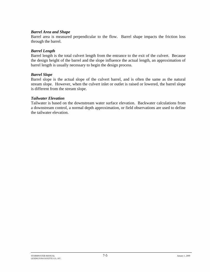
STORMWATER MANUAL 7-5 January 1, 2009 LEXINGTON-FAYETTE CO., KY.
Barrel Area and Shape Barrel area is measured perpendicular to the flow. Barrel shape impacts the friction loss through the barrel. Barrel Length Barrel length is the total culvert length from the entrance to the exit of the culvert. Because the design height of the barrel and the slope influence the actual length, an approximation of barrel length is usually necessary to begin the design process. Barrel Slope Barrel slope is the actual slope of the culvert barrel, and is often the same as the natural stream slope. However, when the culvert inlet or outlet is raised or lowered, the barrel slope is different from the stream slope. Tailwater Elevation Tailwater is based on the downstream water surface elevation. Backwater calculations from a downstream control, a normal depth approximation, or field observations are used to define the tailwater elevation.
STORMWATER MANUAL 7-6 January 1, 2009 LEXINGTON-FAYETTE CO., KY.
7.4 Bridge Design Criteria 7.4.1 General Bridges shall be designed to:
• pass the 100-year flow with one foot of freeboard below the bottom of the bridge structure
• not damage the road or increase damages to adjacent property because of high velocities
• maintain existing flow distribution in the floodplain to the extent practicable • minimize flow disruption and potential scour from pier spacing, pier orientation, and
abutment • avoid failure by scour • pass anticipated debris • provide measures to counteract the sometimes unstable or unpredictable nature of
alluvial streambeds or demonstrate that the risk of damage is low • produce minimal disruption of ecosystems and values unique to the floodplain and
stream • accommodate pedestrian access
7.4.2 Backwater Increases Bridges shall be designed so that flooding to upstream properties is not increased over existing levels. Verify this by conducting a flow profile analysis for the waterway, using the 100-yr storm flow, for conditions prior to and following construction of the bridge. Limit the allowable increase in backwater at the bridge to 1 foot during passage of the 100-yr flow.

STORMWATER MANUAL 7-7 January 1, 2009 LEXINGTON-FAYETTE CO., KY.
7.5 Bridge Design Procedures Use HEC-RAS to evaluate the effects of the bridge.

STORMWATER MANUAL 7-8 January 1, 2009 LEXINGTON-FAYETTE CO., KY.
7.6 Construction Specifications 7.6.1 Circular Culvert Pipe Circular culvert pipe shall be reinforced concrete pipe and shall be installed in accordance with the LFUCG Standard Drawings and KYTC Standard Specifications for Road and Bridge Construction, latest edition. 7.6.2 Box Culverts Box culverts shall be constructed in accordance with the LFUCG Structures Manual.

CHAPTER 8 CONSTRUCTED CHANNELS

STORMWATER MANUAL 8-1 January 1, 2009 LEXINGTON-FAYETTE CO., KY.
8.1 Introduction Constructed channels include permanent constructed channels and temporary diversions. Temporary diversions shall be designed in accordance with requirements of Chapter 11. This chapter describes permanent constructed channels, including paved channels.

STORMWATER MANUAL 8-2 January 1, 2009 LEXINGTON-FAYETTE CO., KY.
8.2 Permanent Constructed Channels Constructed channels include roadside channels and stormwater drainage channels with regular geometric cross-sections and lining of natural or synthetic materials to protect against erosion Safety of the general public shall be an important consideration in the selection of cross-sectional geometry of constructed channels. The design of channels shall consider the frequency and type of maintenance expected and make allowance for access of maintenance equipment. 8.2.1 Design Criteria Constructed channels shall be designed with stable side slopes. Vegetated channels shall have sideslopes of 3:1 or flatter. Constructed channels in residential areas that receive runoff from a storm sewer or culvert shall be constructed with a paved trickle channel. The trickle channel shall be designed to carry 50% of the 1-year storm. A detail is shown in Figure 8-1. Channel freeboard shall be one foot or two velocity heads (velocity head = V2/2g), whichever is larger. Channels with bottom widths greater than 10 feet shall have a minimum bottom cross slope of 12 to 1. Maximum design depth shall be based on the 100-year storm. 8.2.2 Channel Lining Use channel linings to stabilize the slopes and bottoms of constructed channels. Evaluate vegetative lining first. If a vegetated channel is not stable, other alternatives shall be considered in the order shown below:
• vegetative with a turf reinforced mat (TRM) • other hard armor such as gabion mattress, dry stone masonry, tri-loc, etc. • concrete
Where there is a base flow and the channel does not have a natural rock bottom, the bottom of the channel shall have a non-vegetative lining. 8.2.3 Manning’s Equation Use the Manning Equation to design open channels.
STORMWATER MANUAL 8-3 January 1, 2009 LEXINGTON-FAYETTE CO., KY.
Q = (1.49/n)AR2/3 S1/2 Where: Q = discharge, cfs n = Manning’s roughness coefficient A = cross-sectional area of flow, ft2 R = hydraulic radius = A/P, ft P = wetted perimeter, ft S = channel slope, ft/ft Select Manning’s n from Tables 8-1 and 8-2. 8.2.4 Tractive Force After sizing the channel and determining the normal flow depth corresponding to the design storm, check the suitability of the channel lining using the tractive force method. The maximum tractive force at normal flow depth, τd, is calculated as: τd (lbs/ft2) = 62.4yS Where: y = normal depth (ft) S = channel slope. The critical tractive force, τc, for many linings can be found in Table 8-3. If τd < τc, the lining is acceptable. Options for redesign include selecting a more resistant lining or decreasing the flow velocity by decreasing the channel bed slope or side slopes or increasing the width. For linings not listed in Table 8-3, use the manufacturer’s literature to determine the critical tractive force and submit documentation with the design. For mats, nets, or TRMs use the critical tractive force in the unvegetated condition. 8.2.5 Construction Specifications All ditches or other depressions to be crossed shall be filled before construction begins or as part of construction, and the earth fill used to fill the depressions shall be compacted using the treads of the construction equipment. All old terraces, fence rows, or other obstructions that will interfere with the successful operation of the channel shall be removed. The earth materials used to construct the earth fill portions of the channel shall be obtained from the excavated portion of the channel or other approved source.

STORMWATER MANUAL 8-4 January 1, 2009 LEXINGTON-FAYETTE CO., KY.
The earth fill materials used to construct the channel shall be compacted by running the construction equipment over the fill in such a manner that the entire surface of the fill will be traversed by at least one tread track of the equipment. The completed channel shall conform to the cross section and grade shown on the design plans.
TABLE 8- 1 MANNING’S n FOR CONSTRUCTED CHANNELS
Lining Type Manning’s n
Concrete 0.013 Grouted Stone 0.030 Stone Masonry 0.032 Bare Soil 0.020 Rock Cut 0.035 Jute Net 0.022 Straw with Net 0.033 Curled Wood Mat 0.035 6-inch D50 Riprap 0.050 12-inch D50 Riprap 0.060 Grass 0.045
TABLE 8- 2
MANNING’S n FOR STREAMS AND FLOODPLAINS
Manning’s n Streams 0.045 Floodplains Pasture, no brush 0.035 Brush 0.10 Trees 0.120

STORMWATER MANUAL 8-5 January 1, 2009 LEXINGTON-FAYETTE CO., KY.
TABLE 8- 3 SUMMARY OF CRITICAL TRACTIVE FORCES FOR VARIOUS PROTECTION
MEASURES
Protective Cover τc(lbs/ft2) Grass or Grass-legume Mixture Good Stand
1.0
Jute Net 0.45 Straw with Net 1.45 Curled Wood Mat 1.55 Turf Reinforcement Matting (TRM) 6-10 Riprap D50 = 6 inches D50 = 12 inches
2.50 5.00
8.2.6 Maintenance Channels shall be inspected regularly to check for points of scour or bank failure; rubbish or channel obstruction; rodent holes; breaching; and excessive wear from pedestrian or construction traffic. Channels shall be repaired at the time damage is detected. Sediment deposits shall be removed from adjoining vegetative filter strips when they are visible. Channels shall be reseeded and fertilized as needed to establish vegetative cover.

STORMWATER MANUAL 8-6 January 1, 2009 LEXINGTON-FAYETTE CO., KY.
8.3 Paved Channels A paved channel shall be used when the flow velocity at design capacity (using vegetative lining) exceeds 12 fps. 8.3.1 Design Criteria Paved channels shall be designed to carry the peak flow from the 100-year storm. The outlets of paved channels shall be protected from erosion using gabion mattresses. The length of the gabion mattress shall be one foot for each one fps of velocity. The width of the gabion mattress shall extend one foot in elevation beyond the top elevation of the paved channel. Cutoff walls shall be constructed at the beginning and end of each channel except where the channel connects with a catch basin or inlet. 8.3.2 Material Specifications Paved channels shall be constructed of concrete or interlocking concrete blocks. 8.3.3 Construction Specifications The subgrade shall be constructed to the required elevations. All soft sections and unsuitable material shall be removed and replaced with suitable material. The subgrade shall be thoroughly compacted and shaped to a smooth, uniform surface. The subgrade shall be moist when pouring concrete. 8.3.4 Maintenance Before permanent stabilization of the slope, the structure shall be inspected after each rainfall. Any damages to the channel or slope shall be repaired immediately.


CHAPTER 9 STREAMBANK STABILIZATION AND RESTORATION
STORMWATER MANUAL 9-1 January 1, 2009 LEXINGTON-FAYETTE CO., KY.
9.1 Introduction The streams of Fayette County are part of the waters of Fayette County as discussed in Chapter 1. They are shown on the Fayette County GIS waters coverage. The streams of Fayette County are typically those shown on the USGS 7.5 minute quadrangle map with a solid or dashed blue line. However, in some instances streams not shown as blue lines have been found to exhibit the same characteristics as blue line streams and have been added to the Fayette County waters GIS coverage. In general, streams are:
• natural channels with their size and shape determined by natural forces • compound in cross section with a main channel for conveying low flows and a
floodplain to transport flood flows • shaped geomorphologically by the long-term history of sediment load and water
discharge which they experience As indicated in Chapter 1, construction is only allowed in the floodplain and stream for certain activities. The practices listed in this chapter are to be used for two purposes:
• protecting the streambank and floodplain from the construction that must occur • enhancing the stream and floodplain as part of the overall development or stream
restoration plan

STORMWATER MANUAL 9-2 January 1, 2009 LEXINGTON-FAYETTE CO., KY.
9.2 Vegetative Streambank Stabilization 9.2.1 General In some instances, certain allowable construction will result in excavation into the streambank. In those instances when the natural streambank must be disturbed, first consider vegetative streambank stabilization methods. If those methods are not applicable, use bioengineering techniques. Use structural streambank stabilization techniques as a last resort for permanent stabilization except in instances where a small gabion mattress is needed for outlet protection. In no case will gabions be allowed within a stream unless bioengineering methods are not suitable. In other instances, increased runoff may cause the deterioration of a natural streambank. Similarly, a natural streambank that has been previously degraded due to past impacts may be further deteriorated by new development. In these cases, the streambank shall be restored to prevent further degradation using vegetative methods and/or bioengineering techniques. 9.2.2 Design Criteria Planned protective measures shall be compatible with the adjacent land use and the improvements that will be carried out by others. The selection of native vegetation to be established shall be based on the soil type and chemistry, land use, flooding periods, and stream velocity. A list of recommended species is provided in Table 9-1. Soil tests shall be conducted prior to land disturbance activity to determine if soil amendments and/or fertilizers are needed. If soil tests determine that fertilization is required, then application of recommended fertilizer shall not occur until after the vegetation has germinated and established growth. Where necessary, erosion control matting or turf reinforcement matting shall be used along with the vegetative measures to stabilize the streambanks. If traditional vegetative measures described in this section are not effective, bioengineering techniques shall be considered. Special attention shall be given to maintaining or improving habitat for fish and wildlife. On smaller streams where a good seedbed can be prepared, herbaceous plants may be used alone to stabilize the banks. On larger streams and more difficult sites, woody shrubs and trees with herbaceous plants shall be considered. All requirements of state law and permit requirements of local, state, and federal agencies must be met.
STORMWATER MANUAL 9-3 January 1, 2009 LEXINGTON-FAYETTE CO., KY.
9.2.3 Material Specifications Vegetation shall consist of herbaceous ground cover and/or woody shrubs and trees. Installation methods shall include direct seeding and/or the planting of bare root seedlings, hardwood cuttings, and/or containerized plants. Direct seeding shall only be conducted during March 1 to May 15 or August 1 to September 30. Bare root and cutting installation shall only be conducted during December 1 to March 15. Installation of containerized plants shall only be conducted during March 1 to May 15 and September 1 to December 31. The surface shall be mulched with clean wheat straw at a rate of 2 tons per acre. Mulch shall be secured as described in the section on mulch. If mulch tackifiers or related methods are not applicable then erosion control matting or turf reinforcement matting (TRMs) shall be used. Many types of erosion control mats and TRMs are available from various manufacturers. Some are considered temporary because they are manufactured of organic materials that will degrade over time. Due to wildlife endangerment problems associated with the UV resistant mesh in some erosion control matting, only materials with fully degradable mesh shall be used as mulch blankets. Non-degradable products (TRMs) are appropriate where turf reinforcement is necessary. The material shall be chosen based on calculated tractive forces in accordance with manufacturers’ recommendations (See Chapter 8). If nursery stock (bare root or containerized) is used, the species listed in Table 9-1 shall be used for establishing vegetation. Direct seeding of the herbaceous species listed below shall also be used. Selected species shall be based upon the native vegetation of the watershed where work is proposed and shall reflect the original stream bank species. Exotic or pest species shall not be used. See Section 9.4.2 for recommended species and installation requirements of hardwood cuttings. 9.2.4 Construction Specifications Prior to seeding or planting, only fallen trees, stumps, and other debris that may force stream flow into the streambank shall be removed. Leaving other debris may be desirable for aquatic habitat. Where feasible, the streambank side slope shall be cut back to 3:1 slope or flatter and overhanging bank edges shall be removed. Direct seeding areas shall be roughened with a rake or similar tool. Seeding rates shall be a minimum of 10 lbs. per 1000 square feet of disturbed area. Erosion control matting or turf reinforcement matting shall be installed in accordance with manufacturers’ requirements. Erosion control fabrics, blankets, mats and nettings shall be

STORMWATER MANUAL 9-4 January 1, 2009 LEXINGTON-FAYETTE CO., KY.
anchored at the top of streambanks by excavating a shallow trench. The material shall be laid in the bottom of trench with overlap. The trench shall be backfilled with excavated soil. The overlap material shall be laid on top of backfill and secured with dead stout stakes, metal staples, or according to manufacturer’s specifications (see Figure 9-1). Bare root or containerized stock shall be planted at the same depth as planted in the nursery. The stock shall be planted in a hole large enough to accommodate the root system when well spread. Trees and shrubs shall be planted to achieve a minimum density of 300 live stems per acre after three years. 9.2.5 Maintenance Banks shall be checked after every high water event. Gaps in vegetative cover shall be repaired at once with new plants and mulched if necessary. Exotic and pest species that become established on the bank shall be removed.

STORMWATER MANUAL 9-5 January 1, 2009 LEXINGTON-FAYETTE CO., KY.
TABLE 9- 1 SUGGESTED RIPARIAN SPECIES LIST
The species on the list are only suggestions. Native species that are appropriate for a given site may be proposed.
Tree Species Pin Oak Quercus palustris Cherrybark Oak Quercus pagoda Bur Oak Quercus macrocarpa Swamp Chestnut Oak Quercus michauxii Shingle Oak Quercus imbricaria Northern Red Oak Quercus rubra Post Oak Quercus stellata Red Maple Acer rubrum Green Ash Fraxinus pennsylvanica Shellbark Hickory Carya laciniosa Blackgum Nyssa sylvatica American Elm Ulmus americana Eastern Cottonwood Populus deltoides Black Walnut Juglans nigra River Birch Betula nigra Yellow Poplar Liriodendron tulipifera Persimmon Diospyrus virginiana Black Walnut Juglans nigra Ohio Buckeye Aesculus glabra Sugar Maple Acer saccharum Sycamore Plantanus occidentalis Persimmon Diospyros virginiana Shrubs
Arrow-wood Viburnum dentatum American Plum Prunus americana Deciduous Holly Ilex decidua Gray Dogwood Cornus racemosa Silky Dogwood Cornus amomun Spicebush Lindera benzoin Sassafrass Sassafras albinum American Elder Sambucus canadensis Button Bush Cephalanthus occidentalis River Cane Arundinaria gigantea Coralberry Symphoricarpos orbiculatus
STORMWATER MANUAL 9-6 January 1, 2009 LEXINGTON-FAYETTE CO., KY.
Herbaceous Species
Rice cutgrass Leersia oryzoides Managrass Glyceria striata Spangle grass Chasmanthium latifolium Barnyard grass Echinochloa crus-galli Switchgrass Panicum virgatum Annual rye Secale cereale Wild rye Elymus virginicus Deertongue grass Panicum clandestinum Panic grass Panicum microcarpon Giant Cane Bambo Arundinaria gigantea Boneset Eupatorium perfoliatium Big Bluestem Andropogon gerardii Prairie cordgrass Spartina pextinata Water Plantain Alisima subcordatum Common Milkweed Asclepias syracia Beggar’s Ticks Biden polyeps Canada Brome Bromus pubescens American Bellflower Campanula americana Frank’s Sedge Carex frankii Sedge Carex granularis Shallow Sedge Carex lurida Hop Sedge Carex lupulina River Oats Chasmanthium latifolium Riverbank Wild rye Elymus riparius Downy Wild rye Elymus villosus Joe-pie Weed Eupatorium maculatum Fowl Manna Grass Glyceria striata Rush Juncus sp. Western Panic grass Panicum acuminatum Switchgrass Panicum virginica Foxglove Beardtongue Penstemon digitalis Leafcup Polymnia canadensis Brown-eyed Susan Rudbeckia triloba Dark Green Bulrush Scirpus cyprinus Yellow Wingstem Verbesina alternafolia White Wingstem Verbesina virginica

STORMWATER MANUAL 9-7 January 1, 2009 LEXINGTON-FAYETTE CO., KY.
9.3 Riparian Buffer Zones 9.3.1 General Riparian buffer zones are areas of trees and/or shrubs located adjacent to and up-gradient from perennial or intermittent streams, lakes, ponds, wetlands, and areas with groundwater recharge. They may be constructed by Developers to satisfy some or all of the required water quality volume (see Chapter 10). The purpose of riparian buffer zones are:
• to reduce excess amounts of sediment, organic material, nutrients, pesticides, and other pollutants in surface runoff and reduce excess nutrients and other chemicals in shallow groundwater flow
• create shade to moderate water temperatures to improve habitat for fish and other aquatic organisms
• to provide a source of detritus and large woody debris for fish and other aquatic organisms
• to provide riparian habitat and corridors for wildlife 9.3.2 Design Criteria The buffer shall consist of a zone (identified as Zone 1) that begins at the top of bank, and extends a minimum distance of 15 feet, measured horizontally on a line perpendicular to the water course or water body and planted with tree species selected from Table 9-1. An additional strip or area of land (Zone 2) will begin at the edge and up-gradient of Zone 1 and extend a minimum distance of 20 feet, measured horizontally on a line perpendicular to the water course or water body. Zone 2 shall be planted with shrubs and herbaceous ground cover species selected from Table 9-1. The combined width of Zones 1 and 2 shall be 100 feet or 30 percent of the geomorphic floodplain, whichever is less. A geomorphic floodplain is defined as the area adjacent to a river or stream that is built of alluvial sediments that are associated with the present depositional activity. Figures 9-1 and 9-2 illustrate examples of Zone 1 and 2 widths for water courses and water bodies. Zone 2 may need to be adjusted to include important resource features such as wetlands, steep slopes, or critical habitats. Buffers shall be established or maintained from top of bank to waterline along water courses and bodies where practical. The buffer canopy shall be established to achieve at least 50 percent crown cover with average canopy heights equal to or greater than the width of the water course, or 30 feet for water bodies. (See Figure 9-3). Dominant vegetation shall consist of existing or planted trees and shrubs suited to the site and the intended purpose. Selection of locally native species shall be a priority when feasible. Plantings shall consist of six or more species in an attempt to achieve greater diversity. Individual plants selected shall be suited to the seasonal variation of soil moisture
STORMWATER MANUAL 9-8 January 1, 2009 LEXINGTON-FAYETTE CO., KY.
status of individual planting sites. Plant types and species shall be selected based on their compatibility in growth rates and shade tolerance. Necessary site preparation and planting for establishing new buffers shall be done at a time and manner to insure survival and growth of selected species. Refer to Section 9.2 for care, handling, and planting requirements for woody planting stock. Only viable, high quality, and adapted planting stock shall be used. The method of planting for new buffers shall include hand or machine planting techniques, suited to achieving proper depths and placement for intended purpose and function of the buffer. Site preparation shall be sufficient for establishment and growth of selected species and be done in a manner that does not compromise the intended purpose. Refer to Section 9.2 for woody planting stock quality requirements and planting rate densities. Supplemental moisture shall be applied if and when necessary to assure early survival and establishment of selected species. Livestock shall be controlled or excluded as necessary to achieve and maintain the intended purpose. Water course crossings and livestock watering shall be located and sized to minimize impact to buffer vegetation and function. 9.3.3 Maintenance The riparian forest buffer shall be inspected periodically, protected, and restored as needed, to maintain the intended purpose and protect it from adverse impacts such as excessive vehicular and pedestrian traffic, pest infestations, pesticide use on adjacent lands, livestock damage, and fire. Replacement of dead trees or shrubs and control of undesirable vegetative competition shall be continued until the buffer has reached, or will progress to, a fully functional condition. To maintain buffer function, control of erosion and sedimentation shall be continued in the upgradient area immediately adjacent to Zone 2 until the upgradient area is permanently stabilized. For purposes of moderating water temperatures and providing detritus and large woody debris, riparian forest buffer management must maintain a minimum of 50 percent canopy cover. To achieve benefits provided by large woody debris, natural mortality of trees and shrubs may need to be supplemented by periodically falling and placing selected stems or large limbs within water courses and water bodies
STORMWATER MANUAL 9-9 January 1, 2009 LEXINGTON-FAYETTE CO., KY.
9.4 Bioengineering Techniques Bioengineering techniques for streambank protection utilize native vegetation in combination with inert structural materials to stabilize soils that are subject to erosion and shallow mass movement. 9.4.1 Design Criteria Establishing permanent vegetation is the preferred method for stabilizing soils along streambanks. With proper installation and maintenance, the planting of rooted stock, cuttings and direct seeding of native vegetation, in combination with erosion control fabrics, will effectively stabilize soils on slopes of 3:1 or flatter along streams with low flows and no concentrated discharges over the face of the streambank. On streambank slopes of 3:1 or steeper, the techniques described in the following sections (with exception of the Live Staking technique) shall be employed as needed. Each technique is discussed in order of increasing effectiveness of protection based upon the slope of the streambank. The combined use of two or more techniques to accomplish streambank stabilization and protection may be applicable for some sites. When streambanks must be disturbed, slopes shall be regraded to match the adjoining upstream and downstream slopes, if they are stable. If the adjoining slopes are not stable, the disturbed portion shall be regraded to the least gradient possible. Reinforcement shall be provided at the base or toe of the streambank below the mean low waterline prior to implementing bioengineering techniques. Several techniques discussed are applicable for base reinforcement. All work shall begin at the base of the streambank and continue up gradient. For sites involving the discharge of concentrated flow through a streambank and directly into a stream, protection shall be provided for the streambank opposite of the concentrated discharge. Most of the techniques discussed below will be applicable for those sites and are duly noted. 9.4.2 Live Stake Live stakes shall be used in limited situations for streambank slopes of 3:1 or flatter with low flows and no surficial overbank discharge. This technique consists of inserting (tamping) fresh hardwood cuttings into the streambank. This technique is more applicable as a preventive measure before severe erosion problems occur. Live hardwood cuttings shall be collected and installed during the dormant season (November through March) from areas near the site. Drainage ditches, detention ponds, and construction sites can be good sources for materials. The following table provides recommended species for hardwood cuttings. Table 9-1 provides the recommended species for rooted seedlings.

STORMWATER MANUAL 9-10 January 1, 2009 LEXINGTON-FAYETTE CO., KY.
TABLE 9- 2
NATIVE PLANT SPECIES SUITABLE FOR HARDWOOD CUTTING IN CENTRAL KENTUCKY
Common Name Scientific Name
Primary Species: Black willow Salix nigra Sandbar willow Salix interior Heart-leaf willow Salix rigida Silky dogwood Cornus amomum Redosier dogwood Cornus sericea American elderberry Sambucus canadensis Secondary Species: Tall pussy willow Salix discolor Silky willow Salix sericea Dwarf willow Salix humilis var. macrophylla Alternate-leaf dogwood Cornus alternifolia Gray dogwood Cornus racemosa Rough-leaf dogwood Cornus drummondii Boxelder Acer negundo Nannyberry Viburnum lentago Swamp Haw Viburnum nudum Arrowwood Viburnum dentatum
Other practices, in combination with live stakes, shall be used for streambanks that receive high flow fluctuations or consist of fill soils. Stakes (cuttings) shall be 2 to 3 feet in length and 0.5 to 2 inches in diameter with all outer branches removed. Basal end (inserted into ground) shall be sawed clean at an angle. Blunt end (exposed end) shall be cut square. See Figure 9-4A for a live stake detail. Stakes shall be installed within 24 hours of cutting. Temporary storage shall occur in a moist, cool location. Stakes shall be installed at right angles to the slope with 20 percent (1/5) of the stake left exposed. Stakes shall be spaced at a minimum of 2 to 4 per square yard and in a random configuration. Installation shall begin at the base of the streambank working up gradient. Dead blow hammers work the best for installing stakes in soft soils. In cases where stiff soils exist, then pre-drilled holes must be used to accommodate cutting installation. The ground at the base of each stake shall be tamped firm. When erosion control fabrics are necessary, the live stakes shall be used to help secure the material to the face of the streambank.

STORMWATER MANUAL 9-11 January 1, 2009 LEXINGTON-FAYETTE CO., KY.
9.4.3 Root Wad Revetment Root wad revetment techniques can be used for opposite bank protection from concentrated flow discharge and as toe of slope reinforcement with a high flow fluctuation in the stream. This technique is excellent for restoring and improving fish habitats and, when used in combination with proper vegetative methods, is highly effective for stabilizing streambanks. Root wads are tree stumps with a minimum of 6 feet of bole (trunk) above the root flare. The root wads shall be built on top of footer logs and secured with a header log. Footer and header logs shall be secured to the root wad by iron rebar. The bole shall be inserted or placed in the bank at a 30 to 45 degree angle from the downstream line of streamflow, i.e. the root flare shall face upstream. Placed stone shall be used to further secure the root wad system. Filter fabrics may be required in loamy silts or sandy soils. Root wads shall be backfilled with soil and planted with live stakes. Streambank above root wad shall be covered with erosion control fabrics and planted. Figure 9-5 shows the typical construction detail for root wad revetment. 9.4.4 Coir Log Revetment Coir (coconut fiber) log revetments can be used for slope stabilization at the toe of slopes of 2:1 or flatter and as protection for streambanks opposite concentrated discharge points. Coir log revetments shall be used in combination with coir mats or jute netting, planted vegetation and/or live staking. Figure 9-6 provides a detail of staked coir log revetment. Coir logs shall be secured with dead stout stakes inserted down gradient and against logs. Live stakes should be inserted directly into logs. Coir twine should be wrapped around dead stout stakes and over logs to hold them securely to the bank face. Dead stout stakes are 2.5 feet long and 2 inches thick by 4 inches wide (2x4) of untreated lumber that have been cut diagonally across the 4 inch width with a 0.25 inch tip. Figure 9-4B shows in detail how the stakes are cut. 9.4.5 Live Fascine The live fascine technique is applicable on slopes of 2:1 or flatter and utilizes cylindrical bundles of freshly cut willow (Salix spp.), or dogwood (Cornus spp.) branches placed in trenches excavated along the contours of the streambank. Live fascines can also be used to reinforce the toe of streambank slopes. Fascines shall not be used when surficial concentrated flows are discharged over the face of the streambank or where high flow fluctuations occur. When used in combination with coir mats or jute netting and planted vegetation, live fascines can be used on slopes of 2:1 or flatter.

STORMWATER MANUAL 9-12 January 1, 2009 LEXINGTON-FAYETTE CO., KY.
Coir logs shall be used in place of live fascines when bundle materials are not available; however, the coir logs shall be planted with rooted willow, dogwood, or alder. Live fascine bundles can be 5 to 30 feet in length by 7 to 10 inches in diameter and tied together with jute or bailing twine. The bundles are secured with both dead stout stakes and live stakes of fresh cut willow. The cuttings are composed of branches 0.5 to 1 inch in diameter and must be arranged in the bundle with growing tips in the same direction and staggered to evenly distribute growth along the bundle. See Figure 9-7 for construction detail. Small trenches (12 inch by 12 inch) shall be constructed starting at the base of the slope, parallel to the stream channel, and spanning the entire streambank. Parallel trenches shall be constructed along the face of the slope according to the following table:
TABLE 9- 3 LIVE FASCINE TRENCH DISTANCES
Bank Slope
Slope Distance Between Trenches
Maximum Slope Length
2:1 to 2.5:1 5 to 6 feet 20 feet 2.5:1 to 3:1 6 to 7 feet 30 feet 3:1 to 3.5:1 7 to 8 feet 40 feet 3.5:1 to 4:1 8 to 9 feet 50 feet Source: Wright, 1995.
Live fascines shall be placed end to end inside the trenches starting at the base of the slope and working up gradient. Dead stout stakes shall be tamped into bundles every 3 feet along the length and at bundle connections. Trenches shall be backfilled with soil and tamped firm around the fascine. Live stakes shall be tamped in down gradient and against the bundles at right angles to the slope. The live stake procedures in Section 9.4.1 shall be used. 9.4.6 Brush Mattress Brush mattresses are applicable for 1:1 slopes or flatter along streams subject to high flow fluctuations. They can also be used for opposite streambank protection. This technique is limited to streambank faces of 10 feet or less. Brush mattresses require substantial amounts of materials, which including live fascines, live stakes, dead stout stakes, and cut branches. The slope face shall be prepared by smoothly grading the surface and constructing a small trench (12 inch by 12 inch) at the base of the slope, parallel to the stream channel, and spanning the entire streambank. Live fascines shall be installed in the trench as described in Section 9.4.4.

STORMWATER MANUAL 9-13 January 1, 2009 LEXINGTON-FAYETTE CO., KY.
Dead stout stakes shall be installed 3 feet on center in rows parallel to the channel for the entire slope face. Six inches of stake shall be left exposed above the surface. Figure 9-8 shows in detail the layout of the trench and stakes. Pieces of willow and/or dogwood cuttings 8 – 10 feet long shall be placed along the bank with basal ends towards the trench. Enough brush shall be used to create a 6-inch thick mattress. The mattress shall be secured by wrapping wire or coir rope around dead stout stakes in a criss cross pattern between stakes. Work shall begin at bottom of the slope and proceed upgradient. The stakes shall be tapped further into ground to secure the mattress to the bank face. Live stakes shall be inserted between dead stout stakes similar to Section 9.4.1. Cover area lightly with soil and tamp. Do not bury branches. 9.4.7 Branch Packing Branch packing consists of alternating layers of live willow and/or dogwood cuttings and compacted soil secured with wooden poles along a trench. Branch packing is applicable for slopes of 1:1 or flatter that receive surficial discharge over the face of the streambank and high flow fluctuations in the stream channel. This technique can also be used for opposite streambank protection and in areas where severe erosion has resulted in shallow mass movement of the streambank. The trench dimensions for this technique are limited to 12 feet long by 5 feet high and 4 feet deep. Biodegradable filter fabrics shall be used to reinforce soil layers along streams with high flow fluctuations. Placed stone or log cribs shall be used for toe of slope reinforcement at mean low waterline. See Figure 9-9 for a detail on this technique. Wooden poles (4 inches in diameter) shall be untreated and cut at lengths to accommodate the specific depth of the site plus 4 feet. Branch cuttings shall be cut to lengths to accommodate the depth of trench plus 3 feet. The trench shall be excavated clean and the bottom of the site sloped towards the bank from the stream channel. A stone or log crib shall be placed at the outer edge of the excavated area into and below mean low waterline. Dead stout stakes shall be inserted 4 feet deep into the bottom of the trench on 1.5-foot centers. The first layer of brush shall be placed in the bottom of the trench with basal ends towards the bank in a criss-cross pattern 6 inches thick. The first brush layer shall be backfilled with 12 inches of equal parts soil and large gravel. The soil/gravel layer shall be compacted.

STORMWATER MANUAL 9-14 January 1, 2009 LEXINGTON-FAYETTE CO., KY.
This process shall be repeated until the trench is filled. The amount of rock mixed with the soil can be reduced with each successive layer. The compacted bank face should correspond to the adjoining streambank slopes. 9.4.8 Live Cribwall and Log Crib Revetment Live cribwalls are rectangular frameworks of logs or timbers backfilled with soil, rock and live branch cuttings. They are applicable for a bank of any gradient that receives surficial discharge over the bank and high flow fluctuations and where space is limited to stabilize the streambank. This technique is limited in overall height of 6 feet and shall not be used where the adjoining streambed is subject to severe degradation. Figure 9-10 shows a detail for live cribwall. Branch cuttings shall be 0.5 to 2 inches in diameter and 4 to 6 feet long. Logs or timbers shall be 4 to 6 feet long in varying lengths to accommodate site conditions. Timber shall be untreated. Stone shall be 2 to 4 inches in diameter. The work area shall be over excavated 2 to 3 feet below the streambed or toe of bank and sloped back towards bank. Long log or timber shall be placed parallel to the channel and then short logs placed on top and perpendicular. Short logs shall extend to the back of the work area (bank). The logs shall be secured with rebar or spikes. This layer shall be backfilled, covered with 12 inches of rock, and compacted. Build successive layers using rock as backfill until cribwall is above mean low waterline. Use soil backfill in layers above mean low waterline. Compact each soil layer. The layer building process shall be repeated placing live brush cuttings on top of each compacted soil layer. The cuttings shall be placed with basal end towards the bank and the growth ends protruding out from the cribwall. The slope of cribwall shall correspond to the adjoining streambank slope and the final layer shall reach to the top of the original streambank not to exceed 6 feet in overall height. Log crib revetment techniques can be very effective for opposite bank protection or toe of bank reinforcement, especially where high concentrated discharges and high stream flow fluctuations occur. They are similar in construction to live cribwalls with the exception that they are lower in height and no vegetation is used. See Figure 9-11 for a construction detail. 9.4.9 Joint Planting Joint planting is applicable to sites where the use of gabion mattresses or rubble stone to stabilize a streambank has been determined to be the only practical method. This technique is accomplished by inserting live willow stakes between the placed stone. This technique is also applicable where stone is used for toe of bank reinforcement.

STORMWATER MANUAL 9-15 January 1, 2009 LEXINGTON-FAYETTE CO., KY.
Willow tree species are the best for live cutting and shall be a minimum length of 3 to 3.5 feet and 1 to 2 inches in diameter. Planting time and storage specifications are similar to live staking. The stakes shall be inserted in random configuration at a spacing of 3 to 6 stakes per square yard. At least two thirds of the stakes shall extend in to the soil below the stone layer. 9.4.10 Maintenance and Monitoring Streambanks shall be checked after every high water event for six months after completion. Noticeable failures in bioengineering techniques shall be repaired as necessary. Vegetation growth shall be monitored for one year after completion to determine survival rates of planted vegetation. A minimum of 75 percent of designed density must be established by end of the first year after completion. Volunteer species will be considered towards the survival density. Areas of erosion or undermining of streambank adjoining the stabilized portion of the stream shall be noted and monitored to assess whether retrofitting or repairs will be needed. Signs shall be posted indicating a natural area that should not be mowed.
STORMWATER MANUAL 9-16 January 1, 2009 LEXINGTON-FAYETTE CO., KY.
9.5 Structural Streambank Stabilization Structural stream-bank stabilization refers to the stabilization of banks of live steams with permanent structural measures. Generally, the materials and processes are proprietary and include things like interlocking concrete blocks, gabions, gabion mattresses, crib walls, synthetic cellular confinement grids, and dry stone masonry. 9.5.1 Design Criteria Structural stream-bank stabilization shall be used only in cases where vegetative stabilization in conjunction with turf reinforcement matting and vegetative bioengineering will not be effective. Structural stabilization measures shall be planned and designed by an engineer and shall be used, only as necessary, in conjunction with vegetative techniques. Rip-rap may be used if other measures are not feasible. The protective measures shall be compatible with improvements planned or being carried out by others. The bottom scour shall be controlled before any permanent type of bank protection can be considered feasible unless the protection can be safely and economically constructed to a depth well below the anticipated lowest depth of bottom scour. Streambank protection shall start and end at a stabilized or controlled point on the stream. Changes from a natural channel alignment shall not generally be made. Alignment changes in previously modified channels shall be made to take the channel to a more natural alignment and shall consider the effect upon land use, hydraulic characteristics, and the existing channel. Special attention shall be given to maintaining and improving habitat for fish and wildlife. Structural measures must be effective for the design flow and be capable of withstanding greater flows without serious damage. All requirements of state law and permit requirements of local, state, and federal agencies must be met. 9.5.2 Specifications All structural stream-bank protection measures shall be designed and installed in accordance with manufacturer’s standards and specifications.

STORMWATER MANUAL 9-17 January 1, 2009 LEXINGTON-FAYETTE CO., KY.
9.5.3 Maintenance All structures shall be maintained in an “as built” condition. Inspection shall occur each month for the first 6 months after construction and at least every 6 months thereafter. Structural damage caused by storm events shall be repaired as soon as possible to prevent further damage to the structure or erosion of the streambank.

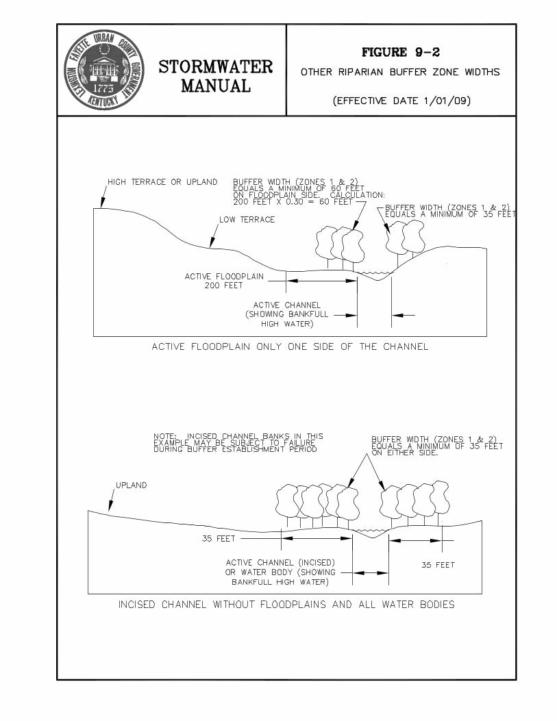
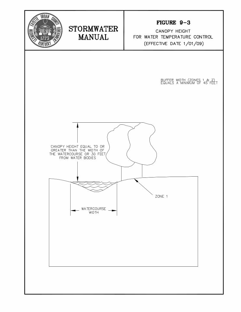
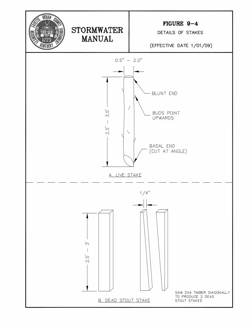

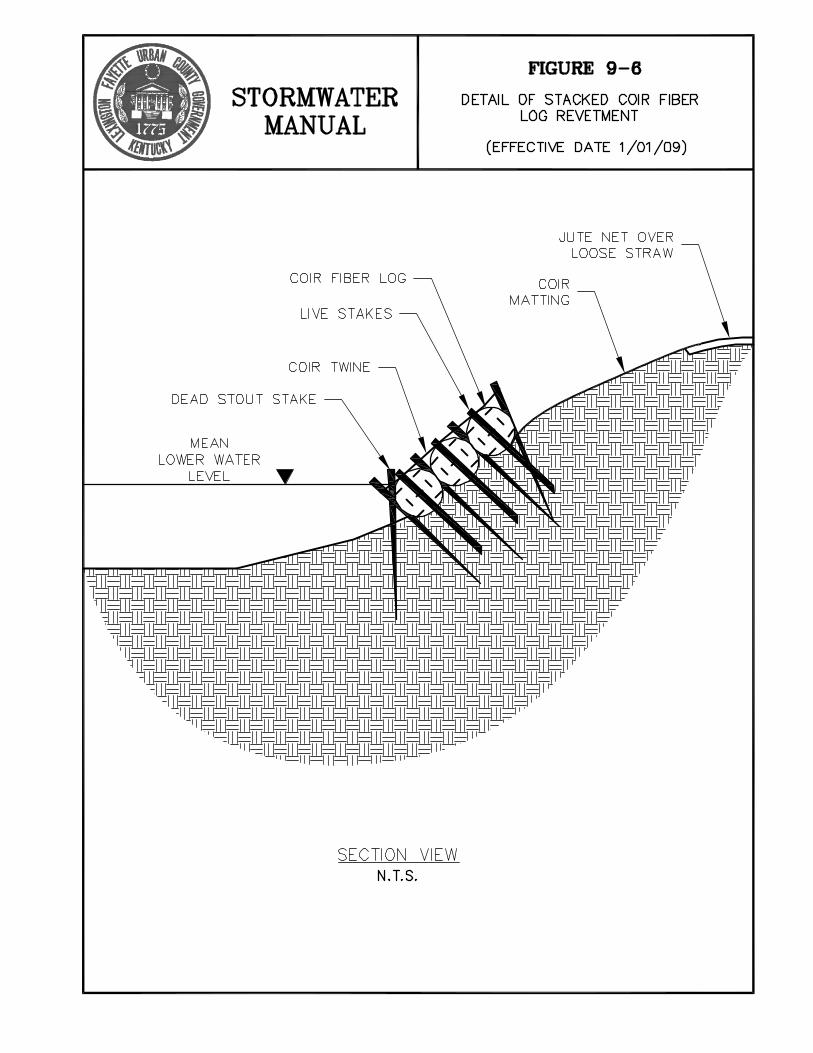

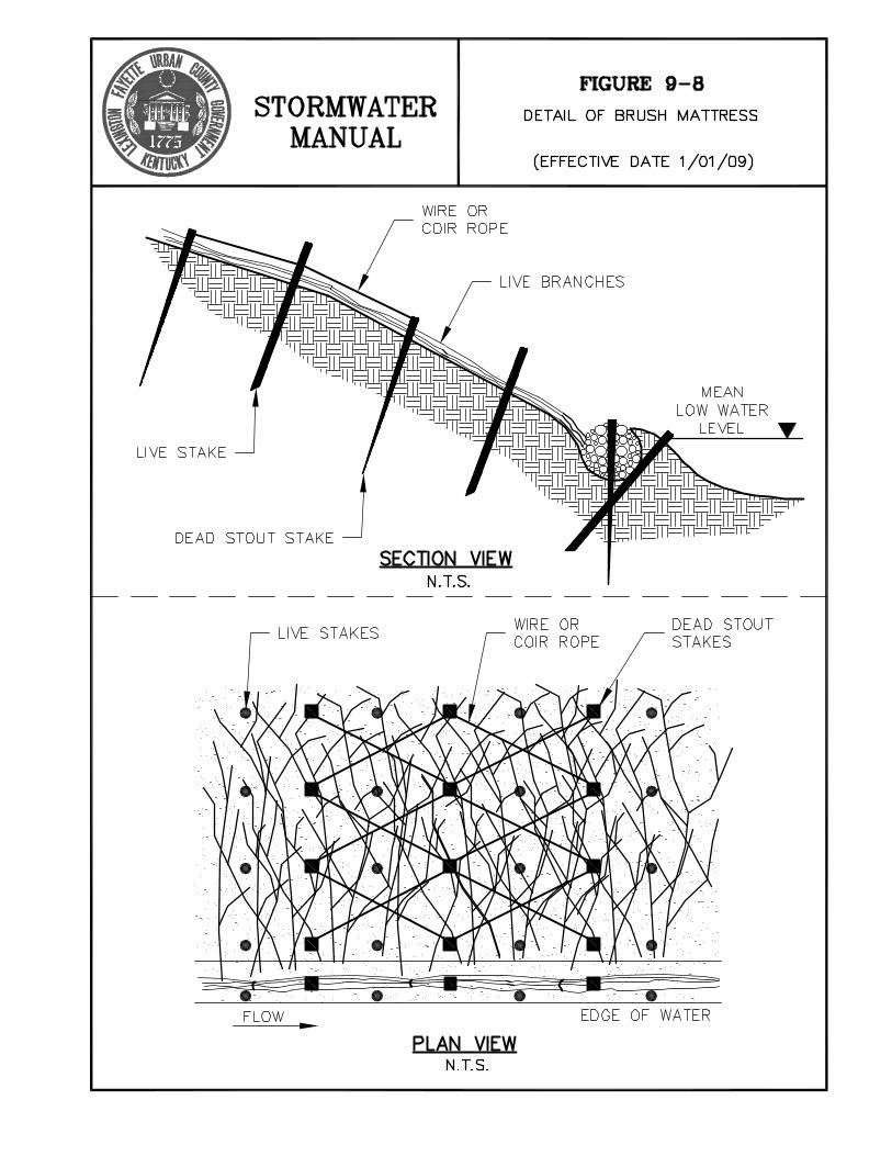
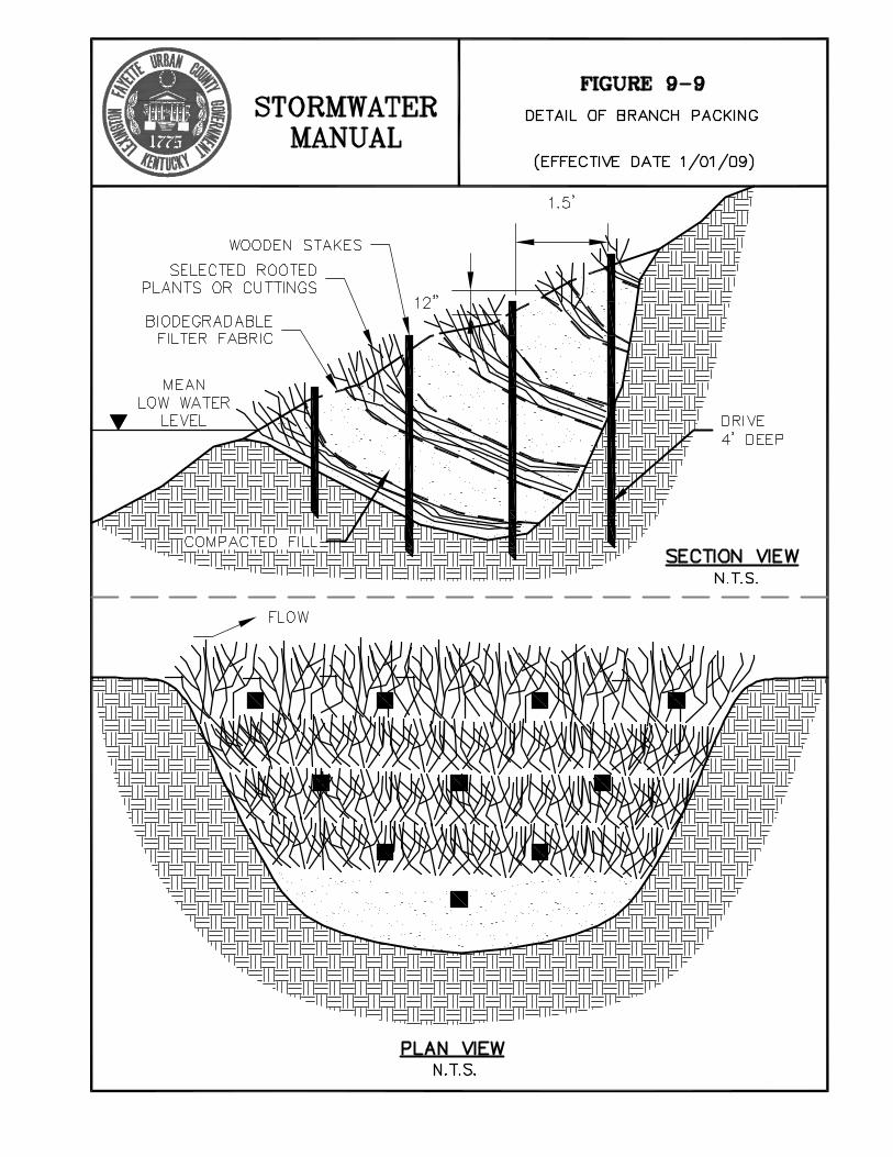


CHAPTER 10 STORMWATER BEST MANAGEMENT PRACTICES FOR WATER
QUANTITY AND WATER QUALITY CONTROL
STORMWATER MANUAL 10-1 January 1, 2009 LEXINGTON-FAYETTE CO., KY.
10.1 Introduction Non-point source pollution is now responsible for up to 80 percent of pollution in waters of the U.S., which include streams, lakes, rivers, and wetlands. This is true, in part, due to significant reductions in direct discharges of pollutants by industry that have been achieved since passage of the Clean Water Act (CWA) of 1972. In urban areas, non-point source pollution occurs because stormwater runoff collects impurities while passing over rooftops, streets, parking lots, landscaping and gutters. This polluted stormwater runoff typically enters a storm drain system and is rapidly conveyed to a lake, stream, or river. The percentage of impervious land cover in urban and suburban watersheds generally indicates the level of pollutant impact on receiving waters. In most cases, impervious cover in excess of 30 percent results in streams that are considered “degraded,” while impervious cover between 10 and 30 percent causes “impacts” on the receiving streams. Typical residential development results in approximately 35 percent of a watershed being impervious, which is more than enough to degrade the receiving waters. Realization of this fact is important, because healthy (non-impacted) streams are important for a healthy ecosystem, and a healthy ecosystem is important for all living creatures including people. To protect our natural resources, the CWA of 1972, as amended in 1987, prohibits the discharge of pollutants to waters of the U.S. and mandates that stormwater not be discharged unless it is in compliance with a National Pollutant Discharge Elimination System (NPDES) permit. LFUCG is responsible for ensuring that discharges of stormwater from public stormwater systems into waters of the state comply with CWA requirements. The implementation of the requirements contained in this manual will be a primary mechanism for accomplishing this objective. Stormwater management in Fayette County shall include management for quality as well as quantity (flood protection). The general policies for control of quality and quantity were given in Chapter 1. This chapter gives detailed design information on the structural water quality and water quantity best management practices (BMPs) to implement these policies. Permanent water quality treatment measures described in this chapter should not be confused with erosion and sediment controls required during construction, which are described in Chapter 11.

STORMWATER MANUAL 10-2 January 1, 2009 LEXINGTON-FAYETTE CO., KY.
10.2 General Design Criteria Stormwater management in Fayette County shall include management for quality and quantity. This section provides the general design criteria for both. 10.2.1 Water Quantity Control Water quantity controls shall be implemented so that post-development peak discharges do not exceed pre-development discharges for those storms listed in Table 5-1. 10.2.2 Water Quality Controls Research has indicated that capturing and treating 90 percent of the total annual runoff volume provides effective water quality treatment volume based on removal of particulates. Effective removal of solid particles in the runoff also provides for removal of significant amounts of nitrogen, phosphorus, and oil and grease. Ninety percent of the annual runoff seems to be a large volume, but the storm events that cumulatively produce this runoff volume in Fayette County produce less than 1.6 inches of runoff each. Using historical rainfall records, typical soil parameters, and the SWMM model, the runoff depth necessary for 90 percent runoff capture was approximated as a function of percent impervious area. These values, which are shown in Table 10-1, represent the water quality depth that shall be treated for each development. For example, a 20-acre development that is 40 percent impervious has a water quality depth of 0.7 inches over the whole area (not just the impervious area), resulting in a water quality volume (WQV) of 50,820 cubic feet. In addition to carrying pollutants, stormwater runoff from developed areas increases the frequency and duration of bankfull flows in the receiving streams, causing increased erosion of the stream banks and further degradation of in-stream water quality. On-site infiltration, designed for the increased runoff due to development, is the preferred solution to this impact.

STORMWATER MANUAL 10-3 January 1, 2009 LEXINGTON-FAYETTE CO., KY.
TABLE 10- 1 WATER QUALITY DEPTH VERSUS PERCENT IMPERVIOUS SURFACE
% Impervious Surface Water Quality Depth (inches)
0 to 9 0 10 0.4 20 0.5 30 0.6 40 0.7 50 0.85 60 1.0 70 1.15 80 1.3 90 1.45
100 1.6 Notes: 1) The Water Quality Volume (WQV) is the volume resulting from applying the prescribed
Water Quality Depth to the drainage area to be developed. 2) For % impervious values between those given use linear interpolation. 3) Water quality controls are not required for sites that are less than 10% impervious.

STORMWATER MANUAL 10-4 January 1, 2009 LEXINGTON-FAYETTE CO., KY.
10.3 Bioretention Systems Bioretention is a practice to treat stormwater runoff using a conditioned planting soil bed and planting materials to filter runoff stored within a shallow depression. The method combines physical filtering and adsorption with biological processes. The system consists of a structure to spread flow, a pretreatment filter strip or grass channel, a sand bed, pea gravel overflow curtain drain, a shallow ponding area, a surface organic layer of mulch, a planting soil bed, plant material, a gravel underdrain system, and an overflow system. Figure10-1 shows a diagram of a bioretention system designed to receive runoff from a paved area. 10.3.1 Applicability Bioretention systems are very effective for water quality treatment. Bioretention systems are particularly well suited for use in parking lot islands, roadside swales, and median strips. 10.3.2 Design Criteria Size the area of the filter bed in accordance with the design WQV corresponding to the area draining to it. (See the next section for procedure). Design the bioretention system to be on-line with an overflow catch basin, as shown in Figure 10-1, to handle volumes exceeding the design WQV. Design the bioretention system to have a longitudinal slope of 0 to 1 percent. Provide a pretreatment system composed of a pea gravel diaphragm and a grassed filter strip. The pea gravel diaphragm also serves as a flow spreader. Dimensions of the gravel diaphragm and grass filter strip shown in Figure 10-1 are minimums. When flow into a bioretention system is parallel to its long dimension (i.e., from a drainage swale), omit the gravel diaphragm shown in Figure 10-1 and provide a berm across the downstream end of the system to impede the flow. The top of the berm shall be level across the base of the bioretention system and be 12 to 18 inches high in the center. Provide a planting soil bed with a minimum width of 4 feet and a minimum depth of 4 feet (including a 12-inch sand bed). The planting soil bed can be as wide as 15 feet. The area of the system is determined by the required area of the filter bed. The minimum length is 15 feet. For widths greater than 10 feet, maintain at least a 2:1 length to width ratio. Provide a pea gravel curtain drain, as shown in Figure 10-1. The minimum width of the curtain drain is 8 inches. Provide a 2 to 3 inch thick mulch layer above the planting soil bed.

STORMWATER MANUAL 10-5 January 1, 2009 LEXINGTON-FAYETTE CO., KY.
Grade the top of the planting soil bed to provide a shallow ponding area with a maximum depth of 6 inches. Provide an underdrain system of gravel and perforated pipe. Design the gravel bed to be at least 8 inches deep. Connect the underdrain to the storm drainage system or design it to daylight to a suitable non-erosive outfall. 10.3.3 Design Procedures Size the filter bed using the following equation: Af = V*(df)/[k*(hf + df)(tf)] where: Af = surface area of the sand filter bed (ft2) V = treatment or infiltration volume (ft3) df = planting bed depth (ft) k = coefficient of permeability for planting bed (ft/day) hf = average height of water above the planting bed (ft); hf = 0.5 * hmax tf = time required for V to filter through the planting bed (days). Note: df = 4 feet (including sand filter) unless it is increased by designer k = 0.5 feet/day (median value of a silt loam) hf = 0.5 * hmax = 3 inches = 0.25 feet tf = 3 days. Design the bioretention system to provide the minimum filter area required and to meet the design criteria. 10.3.4 Specifications Provide planting soil with the following characteristics: • pH of 5.2 to 7.0 • organic content of 1.5 to 4 percent • magnesium of 35 pounds per acre minimum • phosphorus (as P2O5) of 75 pounds per acre minimum • potassium (as K2O) at 85 ponds per acre minimum • soluble salts less than 500 ppm • clay content of 10 to 25 percent by volume • silt content of 30 to 55 percent by volume • sand content of 35 to 60 percent by volume • free of stones, stumps, roots, or other woody material greater than 1 inch in diameter Place planting soil in lifts of 12 to 18 inches and loosely compact or tamp lightly with backhoe bucket.

STORMWATER MANUAL 10-6 January 1, 2009 LEXINGTON-FAYETTE CO., KY.
Provide shredded hardwood mulch aged at least 2 months. Place mulch layer 2 to 3 inches deep. Provide clean river pea gravel for the curtain drain and diaphragm sized to meet ASTM D-448 size no. 6 with diameter ranging from 1/8 to ¼ inch. Provide gravel for the underdrain sized to meet AASHTO M-43 with size range of ½ to 2 inches in diameter. Provide PVC piping for the underdrain satisfying AASHTO M-278 standard for rigid schedule 40 pipe. Provide 3/8 inch diameter perforations on 6-inch centers with four holes per row. Plant base of bioretention system (planting soil bed) in herbaceous ground cover and shrubs. Plant side slopes of bioretention system in herbaceous ground covers, vines, and shrubs. Trees may also be used in the bioretention system. Use direct seeding for herbaceous varieties and nursery stock for vines, shrubs, and trees. Areas to be seeded with herbaceous varieties shall be roughened with a rake or similar tool. Seeding rates shall be minimum of 10 pounds of seed mix per 1000 square feet of area. Bare root or containerized stock shall be planted at the same depth as planted in the nursery. The stock should be planted in a hole large enough to accommodate the root system when well spread. Shrubs and vines shall be planted at a minimum density of 1,700 stems per acre (one stem per 25 square feet at 5 feet on center). Select herbaceous species for the planting soil bed from the following list. Use a minimum of two species.
Common Name Scientific Name Barnyard grass Echinochloa crusgalli Switch Grass Panicum virgatum Swamp Milkweed Asclepias incarnata Giant Cane Arundinaria gigantea Jewelweed Impatiens capensis River oats Chasmanthium latifolia Deertongue Panicum clandestinum Boneset Eupatorium perfoliatum
Select herbaceous species for the side slopes from Table 9-1 in Chapter 9. Also, select vines, shrubs, and trees from Table 9-1.
STORMWATER MANUAL 10-7 January 1, 2009 LEXINGTON-FAYETTE CO., KY.
10.4 Infiltration Systems Infiltration practices and/or bioretention systems reduce the adverse impacts on the receiving waters that result from increasing the impervious area. This chapter describes several infiltration practices that can be used in many different situations. Many of the practices cannot function as the sole water quality infiltration and treatment device, but will provide significant “credits” toward reducing the magnitude of the runoff that must be detained and treated. Infiltration practices include a variety of practices such as directing downspouts to grassed areas and using modular pavement. Infiltration practices also include swales, terraforming, infiltration, and vegetative filters. Terraforming is a term for special grading practices such as terracing and berming that are intended to promote infiltration. This section presents infiltration practices and describes the minimum requirements that must be met to obtain credits to reduce water quality treatment volumes. The infiltration volume credit listed for each practice can be used to satisfy an equal amount of water quality volume. 10.4.1 Downspouts to Grass Discharging downspouts from roofs onto grassed yards encourages infiltration and reduces direct discharge to impervious areas such as driveways. The grass area shall be greater than or equal to the roof area. Infiltration Credit When downspouts are discharged onto grass, the infiltration credit is 0.225 acre-feet per acre of roof area. Design Criteria The lot must be graded so that the downspout discharge travels at least 30 feet over grass before reaching a driveway, roadway, paved ditch, or any other impervious conveyance. 10.4.2 Modular Pavement Modular pavement consists of strong structural materials, typically concrete, having regularly interspersed void spaces that are filled with pervious materials such as sand, gravel, or sod. These pavements can be used as driveways or as overflow parking in areas that are used less frequently than the main parking areas for civic, commercial, and industrial facilities. Modular pavement can be used for any portion of parking up to that amount allowed by the LFUCG Planning Commission. Infiltration Credit Any area that is paved using modular pavement can be treated as pervious for purposes of calculating WQV and post-development peak runoff, as long as appropriate design criteria and construction specifications are satisfied.

STORMWATER MANUAL 10-8 January 1, 2009 LEXINGTON-FAYETTE CO., KY.
Design Criteria Large void spaces in modular pavement shall represent at least 30 percent of the total surface area of the pavement. Voids shall be filled with silty soil and vegetated with permanent grass. If vegetation is inappropriate, voids may be filled with sand or gravel, but the material shall be clean and uniform (poorly graded) to ensure high permeability. Construction Specifications Install all modular pavements following manufacturer’s specifications. To prevent premature clogging and/or failure, modular pavements shall not be placed into service until the entire contributing surface drainage area has been completely stabilized. Clearly mark the planned area for modular pavement to prevent heavy equipment from compacting the underlying soils. Excavate the subgrade soil using equipment with tracks or oversized tires to minimize compaction. 10.4.3 Swales Swales are typically vegetated parabolic or trapezoidal channels with a large width to depth ratio that are used for conveying stormwater runoff. Swales can act both as vegetated filters and infiltration practices because they tend to slow runoff rates and allow for both particle settling and stormwater infiltration. Swales are encouraged wherever they can be used as an alternative to narrower, deeper channels that tend to convey flow at higher velocities. Swales are especially effective in reducing water quality impacts when used for roadside drainage instead of the traditional curb inlet/storm sewer system. In this application, curb cuts are used instead of drop inlets in the gutter. See Figure 10-2. Swales can be even more effective when constructed using berms or infiltration beds to encourage additional ponding and infiltration. These cases are discussed in subsequent sections. Infiltration Credits When swales are used, the infiltration credit is 0.25 acre-feet per acre of swale. To obtain this credit, the area draining to the swale must be at least three times the area of the swale considering that the swale itself is part of the drainage area. To calculate the area of the swale, the width will be the average water surface width corresponding to the flowrate associated with the 100-year storm.
STORMWATER MANUAL 10-9 January 1, 2009 LEXINGTON-FAYETTE CO., KY.
Design Criteria To be considered a swale, a channel must have a width to depth ratio of at least 6:1, have a bed slope of not greater than 4 percent, and be vegetated. When swales are used for roadside drainage, curb cuts shall be provided no less frequently than one per each 100 feet of curb. Drop inlets in swales shall be spaced no closer than once per each 300 feet in order to obtain the infiltration credit. Grassed channels that do not satisfy the design criteria to be considered swales may be given an infiltration credit only for the channel bottom, if the bed slope does not exceed 4 percent. 10.4.4 Bermed Swales A bermed swale or infiltration swale is a grassed swale constructed with berms or swale blocks across the swale to impound shallow pools of water, slowing flow and providing additional opportunities for particle settling and stormwater infiltration. Infiltration Credit Infiltration credit for a bermed swale is calculated in the same manner as the credit for a swale, except that the calculated infiltration credit can be increased by 50 percent of the water volume that can be impounded by the berms. Design Criteria Swale blocks or earthen berms built across the swale shall be constructed with a 2-inch diameter PVC pipe through the berm to prevent long-term ponding of water. Berms shall be no taller than 8 inches and spaced no closer than 60 feet. Drop inlets in swales shall be spaced no closer than once per each 300 feet in order to obtain the infiltration credit. Grassed channels that do not satisfy the design criteria to be considered swales may be given an infiltration credit only for the channel bottom, if the bed slope does not exceed 4 percent. 10.4.5 Biofiltration Swales A biofiltration swale is a version of a bioretention system without the pipe underdrain system. This practice encourages infiltration from the swale bottom, through a planting bed, to the underlying soil. See Figure 10-3. Infiltration Credit Infiltration credit for a biofiltration swale is 0.50 acre-feet per acre of swale plus 100 percent of the volume of the ponded water, when designed according to the following criteria. If biofiltration swales are designed consistent with the procedures for bioretention systems, the infiltration credit equals the design treatment volume.

STORMWATER MANUAL 10-10 January 1, 2009 LEXINGTON-FAYETTE CO., KY.
Design Criteria Biofiltration swales shall be designed to have the following characteristics:
• trapezoidal or parabolic shape • bottom width of 2 feet • side slopes no steeper than 3:1 • longitudinal slope of 1 to 2 percent (up to 4 percent slope can be used with berms
constructed as required for bermed swales) • length, width, depth, and slope necessary to provide surface storage of the design
volume with a maximum ponded depth of 18 inches • vegetated in accordance with requirements for vegetated channels with grass lining • capacity to convey the 100-year design storm with at least 6 inches of freeboard • a soil bed 36 inches deep having the width of the swale bottom
Plan the soil bed to consist of soils that have a permeability of at least 0.5 feet per day (USCS soils ML, SM, or SC). If native soils do not satisfy this criterion, a prepared soil bed can be designed. An alternative to the above criteria is to size the filter bed (i.e., planting soil bed) for a biofiltration swale consistent with a bioretention system. Then the infiltration credit would be calculated in the same manner as the credit for bioretention. 10.4.6 Terraforming Terraforming is a term for special grading practices such as terracing and berming that are intended to promote infiltration. Bermed swales are a special case of terraforming. Terraforming can range from a small depression in permeable soil to an extensive series of bermed terraces. A simple example is given in Figure 10-4. Infiltration Credit The infiltration credit for terraforming is 0.25 acre-feet per acre of area terraformed plus 100 percent of the impounded water. 10.4.7 Infiltration Basins Infiltration basins may be used in locations that have at least 5 feet of soil, with a permeability of at least 0.5 inches/hour underlying the device. The underlying 5 feet of soil must also be above the seasonal high water table. If soils do not meet the permeability requirement, they can be modified by mixing sand and gravel in the top 5 feet of the soil underlying the device. If native soils are to be modified with sand or gravel, provide a design that shows the depth of soil to be modified and the total quantity of gravel or soil to be added. Include soil test data documenting the permeability of the soils before and after modification.

STORMWATER MANUAL 10-11 January 1, 2009 LEXINGTON-FAYETTE CO., KY.
If desired, large infiltration basins can be designed much like an extended detention pond for storm peak control. The outlet structure and detention storage volumes are designed to be above the level needed to store the design WQV. The difference is that an infiltration basin does not have an extended detention outlet. Instead, the WQV is allowed to infiltrate into the soils underlying the basin. If the infiltration basin is not intended for peak flow control, it shall be designed so that volumes exceeding the WQV can discharge through an overflow weir or pipe. For small excavated basins of less than one-fourth acre, volumes exceeding the WQV may be allowed to overflow onto the ground surface without use of an overflow structure, if proper erosion control measures are implemented. The infiltration credit for an infiltration basin is simply the volume designed to be impounded before overflow or discharge to a spillway. Design Criteria Test soils prior to designing an infiltration basin to ensure that the site is capable of infiltration. Obtain a minimum of three soil test borings or test pits to verify that the soil is at least 5 feet deep below the base elevation and has a permeability of at least 0.5 inch/hour. Design the floor of the basin to be as flat as possible to promote infiltration. Provide side slopes not greater than 3:1 (h:v). Provide a sediment forebay at the inlet to the basin with a depth of at least 4 feet and a volume of at least 10 percent of the WQV. Size the basin to store the design WQV before discharging through the peak flow control outlet. If the basin is intended only for water quality treatment, design an outlet that allows volumes in excess of the WQV to discharge to a surface water conveyance. If a base flow will be discharged into the infiltration basin, design a low flow orifice to allow base flow to pass through. Adjust the storage depth so that the basin will completely drain the WQV in 72 hours. When using an infiltration basin for peak flow control, provide a minimum of 1 foot of freeboard above the 100-year design storm high water elevation. Impoundment depths shall not exceed 15 feet and storage volumes shall not exceed 25 acre-feet. Design earthen embankments with side slopes not steeper than 3:1 (horizontal to vertical). Design basins to be placed outside the receiving stream except when a basin is designed as a regional detention basin and LFUCG has approved its use as a regional basin. Reserve adequate access from public or private right-of-way by establishing a maintenance easement. Design the access to be at least 10 feet wide, with a slope not greater than 5:1

STORMWATER MANUAL 10-12 January 1, 2009 LEXINGTON-FAYETTE CO., KY.
(h:v). Design the access way to connect to the embankment so that equipment can access the top of the embankment on a slope not greater than 5:1 (h:v). Provide a minimum 25-foot wide buffer strip between the basin and the nearest lot. Landscape the buffer strip with low-maintenance native grasses, shrubs, and trees. Provide a landscaping plan for the basin and the buffer. Objectives of landscaping include improving the appearance for adjacent residents and providing wildlife habitat. Specifications Embankment, outlet, and emergency spillway specifications are consistent with those for detention basins. Excavate the basin with light equipment having tracks or over-sized tires to minimize compaction of the underlying soils. After the basin is excavated to the final design depth, deeply till the basin floor with a rotary tiller or disc harrow to restore infiltration rates. After tilling, apply a leveling drag. Establish vegetation immediately after achieving final grade and preparing the infiltration bed. Stabilize the floor of the basin with a dense cover of water-tolerant herbaceous species consistent with requirements of bioretention systems. 10.4.8 Vegetated Filter Strips A vegetated filter is a practice that relies upon the use of vegetation to filter out sediment and other pollutants from stormwater runoff. These filters also provide an opportunity for stormwater runoff to infiltrate. Vegetated filters can be used as water quality devices. Vegetated filters can be used for small subareas of a larger development in order to reduce the total volume to be treated by other devices in the development. A filter strip is a practice that relies upon sheet flow across the entire width of the vegetated area. The vegetation is typically grass; however, other ground cover can be used if it provides for dense vegetation. Filter strips are typically used at the edge of a parking lot or other paved surface. Design Criteria Design a filter strip to have a width matching the width of the area draining to the filter. Design a filter strip to have a smooth transition with the area draining to it so that sheet flow can be developed across the filter. Design filter strips to have a minimum slope of 2 percent and a maximum slope of 6 percent. Provide a dense turf or other comparable vegetated ground cover over the whole filter area. When the contributing area draining to the filter strip is impervious, do not allow the overland flow length of the impervious surface to exceed 75 feet.

STORMWATER MANUAL 10-13 January 1, 2009 LEXINGTON-FAYETTE CO., KY.
When the contributing area draining to the filter strip is pervious, do not allow the overland flow length of the contributing surface to exceed 150 feet. Infiltration Credit The infiltration credit for vegetated filters is 0.075 acre-feet per acre of filter. 10.4.9 Riparian Buffers Riparian buffers are vegetated zones of trees and/or shrubs adjacent to and upgradient from perennial or intermittent streams, lakes, ponds, and wetlands. See Chapter 9 for more information. In the ideal scenario, native riparian buffers would exist adjacent to all receiving waters. However, in many agricultural areas the native riparian buffer has been partially or fully removed to create pasture or cropland right up to the top of streambank. Existing riparian buffers cannot be used for infiltration or water quality credit, but restoration or reforestation of riparian buffers can be used to provide infiltration credit. Design Criteria Design a plan for riparian buffer reforestation/revegetation in accordance with requirements of Chapter 9. In order to obtain infiltration credit for re-establishing a riparian buffer zone, the streambank must also be restored in accordance with Chapter 9. Infiltration Credit The infiltration credit for re-establishing a riparian buffer zone is 0.5 acre-feet per acre of buffer restored. In order to obtain this credit, a buffer zone planting plan must be included with the improvement plans. The plan shall also provide for maintenance of the buffer zone until such time as trees and shrubs are established and the upgradient drainage area is permanently stabilized.

STORMWATER MANUAL 10-14 January 1, 2009 LEXINGTON-FAYETTE CO., KY.
10.5 Sand and Organic Filters In general usage, stormwater filters are a diverse group of techniques for treating stormwater quality with each using some sort of filtering media such as sand, soil, gravel, peat, compost, or vegetation. Filters will include systems with a designed filter bed composed of sand, gravel, compost, or peat and an outlet to the stormwater drainage system or a receiving stream. Systems described in this section include surface sand filters, underground sand filters, perimeter sand filters, and organic filters. 10.5.1 Applicability Filters can be used for water quality treatment, but are not appropriate for peak flow (quantity) control. 10.5.2 General Design Criteria Design criteria in this section apply to all filtration devices in this section. Provide a pretreatment cell to allow sedimentation prior to the filter bed and reduce clogging. Locate inlet and outlet structures at extreme ends of the pretreatment cell. Design the pretreatment or sedimentation cell to have a minimum depth of 3 feet to minimize resuspension and turbulence. Design the bottom of the pretreatment cell to be nearly level to facilitate sedimentation. Design the surface area of the pretreatment cell (in square feet) to be at least 0.0081 times the WQV (in cubic feet) for areas with 75 percent or more impervious surface. For areas with less than 75 percent impervious surface, design the surface area of the pretreatment cell (in square feet) to be at least 0.066 times the WQV (in cubic feet). The order of magnitude difference in the two factors derives from the fact that areas with higher percentages of impervious surface (i.e., 75 percent or more) tend to have a greater proportion of coarse-grained sediments, which have a higher settling velocity. Size the pretreatment cell with a minimum length to width ratio of 2:1. The length to width ratio of the pretreatment cell can be less than 2:1 if baffles are provided to obtain a flow length equivalent to or greater than would be obtained with a 2:1 ratio. Design each filtering device for a capture or storage volume equal to or greater than ¾ times the WQV. Design filtration systems to be off-line by using a flow-splitter or other device to divert flows in excess of the WQV around the filtration systems.
STORMWATER MANUAL 10-15 January 1, 2009 LEXINGTON-FAYETTE CO., KY.
Provide sufficient access to the device for construction and maintenance. Provide an access ramp with a maximum slope of 10 percent for vegetated ramps, 15 percent, if the slope is stabilized with crushed stone, or 25 percent if paved. Construct exposed piping and accessories out of durable, strong materials to avoid susceptibility to damage by vandalism. Provide access manholes and/or grates to underground and below grade structures for each subsurface chamber. Provide manhole diameters of at least 30 inches to meet confined space access criteria. Place manhole steps to allow maintenance personnel easy access to structure bottoms. Provide a 5-foot minimum height clearance (from the top of the sand layer to the bottom of slab) for all fixed permanent underground structures. Provide lifting rings or other suitable elements to lift and replace structure top slabs. Construct the underground sand filter with a dewatering gate valve located just above the top of the sand filter bed. Should the filter bed and/or underdrain system clog completely, the gate valve can be opened to dewater the filter chamber for needed maintenance. 10.5.3 Surface Sand Filter A surface sand filter is shown in Figure 10-5. This system is constructed of reinforced concrete with a pretreatment (sedimentation) chamber and a filter bed chamber with a sand filter and underdrain system. Figure 10-5 also shows a flow diversion chamber at the inlet end of the structure. The filter bed has an 18-inch to 24-inch sand layer which traps or strains pollutants before runoff is collected in an underdrain system (gravel and perforated pipe) and conveyed to the receiving stream, channel or pipe. The filter bed surface may have a sand or grass cover. Surface sand filters are open at the top, which provides easy access for maintenance, but renders these unsuitable in areas easily accessible to the general public, especially small children. Control access to surface sand filters by enclosing them in an eight-foot chain link fence. Such a configuration is most suitable to industrial and warehousing facilities rather than commercial/retail establishments where aesthetic impact is significant. Even for industrial sites, consider proximity to residential areas and other locations frequented by children. In some locations, an eight-foot fence may not provide adequate protection. Design Procedures Size the pretreatment chamber in accordance with design criteria in 10.5.2. Size the area of the filter bed using the following equation: Af = WQV*(df)/[k*(hf + df)(tf)] where: Af = surface area of the sand filter bed (ft2) WQV = water quality treatment volume (ft3) df = sand filter bed depth (ft)

STORMWATER MANUAL 10-16 January 1, 2009 LEXINGTON-FAYETTE CO., KY.
k = coefficient of permeability for sand bed (ft/day) hf = average height of water above the sand bed (ft); hf = 0.5 * hmax tf = time required for the WQV to filter through the sand bed (days). Note:
• set df such that 1.5 feet < df < 2 feet • hf can vary depending on the site conditions, but six feet is the maximum value. • Use 1.7 days (i.e., 40 hours) for the filter bed draw-down time (tf). • Use k = 3.5 ft/day.
Design the underdrain system beneath the filter bed to be at least six inches deep, with at least two inches of gravel over drain pipes and pipe slopes of at least 0.5 percent. Design the underdrain system to ensure that the flow through rate of the filter bed is controlled by the filter media rather than the underdrain system. Calculate the minimum volume which must be stored within the device as Vmin = 0.75 (WQV). Compute the water volume within the filter bed as Vf = Af * 0.35 * (df + du), where df is the depth of the sand bed and du is the depth of the gravel underdrain. The constant 0.35 represents the porosity of the sand and gravel. Figure 10-6 provides an illustration of the parameters used for calculating storage volume. Compute the temporary storage volume above the filter bed as Vf – temp = 2 * hf * Af. Compute the remaining volume required for the pretreatment chamber as Vs = Vmin – (Vf + Vf-temp). Check that Vs is approximately 50 percent of Vmin. If it is not, decrease hf and recompute. Note that changing hf will change the computed Af. Calculate the height in the pretreatment chamber, hs, as hs = Vs/As. Check that hs is greater than 2 * hf and hs is greater than 3 feet. If not, adjust hf and repeat computation. Design a junction box flow splitter with either a pipe or weir overflow to the stormwater system. Set the invert of the overflow to the elevation of the design water level in the pretreatment chamber. Design the overflow to convey the peak discharge anticipated from the 10-year storm. Design the structural concrete components in accordance with design loads and site soil conditions. Specifications Select sand to meet AASHTO M-6 or ASTM C-33 requirements for medium aggregate concrete sand with size range of 0.02 to 0.04 inches.
STORMWATER MANUAL 10-17 January 1, 2009 LEXINGTON-FAYETTE CO., KY.
Select underdrain gravel to meet AASHTO classification M-43 with size range of 0.5 to 2 inches. Select geotextile fabric to have a minimum puncture strength of 125 pounds (ASTM D-751), minimum mullen burst strength of 400 psi (ASTM D-1117), and minimum tensile strength of 300 pounds (ASTM D-1682). Geotextile fabric shall have an opening size equivalent to U.S. sieve size #80 and shall provide a minimum flow rate of 125 gallons/minute per square foot. Select underdrain piping to meet AASHTO M-278 requirements for Schedule 40 PVC pipe. Provide 3/8-inch perforations on 6-inch centers with four holes per row. Construct the base of the sand filter structure on undisturbed soil or rock. If disturbed soil must be used as a base, recompact it to 95 percent of maximum standard dry density in 6-inch compacted lifts. Do not allow runoff to enter the sand filter bed until the upstream drainage area is completely stabilized and site construction is completed. The sedimentation pond may serve as a temporary sediment control pond during site construction with the provision that overflows will bypass the filtration bed. Construct the top of the filter bed completely level. Store materials which might be damaged during construction (such as perforated PVC piping, geotextiles, etc.) in a safe location and handle carefully. Construct overflow weirs, multiple orifices and flow distribution slots completely level to ensure adequate distribution of design flows. Construct the main collector pipe for underdrain systems at a minimum slope of 0.5 percent. Provide observation and clean-out pipes for all underdrain piping. 10.5.4 Underground Sand Filter Underground sand filters are suitable for intensely developed urban areas where space is at a premium. These systems are also suitable in locations that are easily accessible to the public. Figure 10-7 shows an underground sand filter. In this design, the sand filter is placed in a three chamber underground vault accessible by manholes or grate openings. The first chamber is a 3-feet deep sediment chamber used for pretreatment. It is connected to the second chamber (the sand filter bed) by an inverted elbow or submerged slot, which keeps the filter surface free from trash and oil. The filter bed is 18 to 24 inches in depth and has a protective screen of gravel over filter fabric to act as a pre-planned failure plane that can easily be replaced when the filter surface becomes clogged. During a storm, the water quality volume is temporarily stored in both the first and second chambers. Flows in excess of the filter’s capacity are diverted through an overflow weir.
STORMWATER MANUAL 10-18 January 1, 2009 LEXINGTON-FAYETTE CO., KY.
Design Procedures Design procedures are consistent with those described previously for a surface sand filter with the following exceptions. See Figure 10-8 for an illustration of the volume parameters. After computing the minimum volume which must be stored (Vmin) and the volume in the filter bed (Vf), compute the minimum wet pool volume in the settling basin as Vw = 3 ft * As.. Compute the temporary storage volume required within both chambers as Vtemp = Vmin – (Vf + Vw). Compute the total surface area of both chambers as (Af + As). Calculate the height of temporary storage needed as htemp = Vtemp/(Af + As). Check that htemp is greater than or equal to 2hf. If not, decrease hf and recalculate volume requirements. Specifications Specifications are consistent with those provided for surface sand filters with the following addition. To help extend the design life of the sand filter bed for the underground sand filter, place a wide mesh geotextile screen on the surface of the filter bed to trap the large quantities of trash, litter, and organic detritus associated with highly urban areas. During maintenance operations the screen is rolled up, removed and cleaned, and reinstalled. 10.5.5 Perimeter Sand Filters The perimeter sand filter consists of two parallel trench-like chambers that are typically installed along the perimeter of a parking lot. Figure 10-9 shows a perimeter sand filter. Parking lot runoff enters the first chamber that has a shallow permanent pool of water. The first trench provides pretreatment before the runoff spills into the second trench, which consists of an 18-inch deep sand layer over a gravel/perforated pipe underdrain system. During a storm event, runoff is temporarily ponded above the normal pool and sand layer, respectively. When both chambers fill up to capacity, excess parking lot runoff is routed to a bypass drop inlet. Design Procedures Design procedures are consistent with those described previously for a surface sand filter with the following exceptions. See Figure 10-10 for an illustration of the volume parameters. After computing the minimum volume which must be stored (Vmin) and the volume in the filter bed (Vf), calculate the minimum wet pool volume in the pretreatment basin as Vw = As * 2 ft. Calculate the temporary storage volume required as Vtemp = Vmin – (Vf + Vw).

STORMWATER MANUAL 10-19 January 1, 2009 LEXINGTON-FAYETTE CO., KY.
Compute the total surface area of both chambers as (Af + As). Check that htemp is greater than or equal to 2hf. If not, decrease hf and recompute areas and volumes. Note that changing hf will change the required Af. Specifications Specifications are consistent with those given for a surface sand filter. 10.5.6 Organic Filters Organic filters are designed consistent with surface or underground filters except that the sand filter bed is replaced or modified with organic media. There are two basic options for organic filters: a peat-sand system and a compost system. In the peat-sand system, the filter bed is a minimum of 24 inches deep over the underdrain system. This 24-inch bed consists of a 6-inch sand layer overlain by an 18-inch layer of peat-sand mix. The compost filter system consists of a fabricated leaf compost filtration bed overlying the underdrain system. The compost must be mature and humic so that the organic material is no longer rapidly decaying, and it must be locally available at a reasonable cost. Design Procedures Design procedures are consistent with those given previously for surface sand filters or underground sand filters except that the coefficient of permeability, k, for the organic filter is modified. For a peat-sand system, use k = 2.75 ft/day. For a compost system, use k = 8 ft/day. Specifications For peat-sand filter beds, select a fibric peat that is shredded, uniform, and clean. For peat-sand filter beds, combine equal volumes of peat and sand and mix to obtain uniform distribution of peat and sand. Sand specifications are given in Section 10.5.3. For peat-sand filter beds, place a 6-inch layer of sand over the gravel underdrain. Separate the sand layer from the gravel layer with geotextile fabric. Select sand and geotextile consistent with specifications in Section 10.5.3. Above the 6-inch sand layer, place 18 inches of the 50/50 peat-sand mixture. Construct the filter bed so that the surface of each layer is level. Provide nominal compaction of the gravel and sand layers using a mechanical tamper. Do not compact the sand-peat layer. For a compost filter bed, select a compost that is mature and humic, composed of leaf medium rather than general yard waste compost.

STORMWATER MANUAL 10-20 January 1, 2009 LEXINGTON-FAYETTE CO., KY.
For a compost filter bed, place a minimum of 18 inches above the geotextile overlying the underdrain system. Do not compact the compost filter bed.

STORMWATER MANUAL 10-21 January 1, 2009 LEXINGTON-FAYETTE CO., KY.
10.6 Prefabricated Treatment Devices Several manufacturers produce devices that are effective in removing suspended solids and floating oils from stormwater runoff. These devices are typically well-suited to sites that are relatively small and have a high percentage of impervious cover. These devices are not as effective in applications where a majority of the ground cover is pervious and a high percentage of the suspended solids are eroded fine soil particles. Contact the LFUCG Division of Engineering for a list of approved products. 10.6.1 Design Criteria The treatment devices shall be capable of demonstrating 80% capture of particles in a size range of 2 mm (very coarse sand) to 0.125 mm (very fine sand). The design storm shall have an intensity of 2.1 inches/hour (3-month frequency storm with a time of concentration of 10 minutes).

STORMWATER MANUAL 10-22 January 1, 2009 LEXINGTON-FAYETTE CO., KY.
10.7 Detention Ponds A detention pond is a traditional stormwater quantity control device that is designed for peak discharge control. Detention ponds are designed to completely drain after the design storm passes. Figure 10-11 illustrates a detention pond. 10.7.1 Applicability Detention ponds are not effective as water quality treatment devices and can only be used for water quantity control (i.e., detention). 10.7.2 Design Criteria Design detention ponds so that discharge rates do not exceed calculated pre-development peak runoff rates for the storms given in Chapter 5. Design outlet structures so that detention volume is released within 24 hours. Provide an emergency spillway sized to discharge the peak runoff from the 100-year storm assuming the principal spillway is clogged, without overtopping the crest. Provide a minimum of 1 foot of freeboard above the calculated high water elevation for the 100-year storm. Embankment heights shall not exceed 20 feet (measured from the downstream toe) and storage volumes shall not exceed 25 acre-feet and shall not be less than 0.3-acre feet. Regional facilities may exceed these limits, but they must comply with the applicable requirements of the Kentucky Division of Water. Design earthen embankments with side slopes not steeper than 3:1 (horizontal to vertical). Provide anti-seep collars where the spillway barrel passes through the embankment. Stabilize earthen embankments immediately with temporary or permanent vegetation in accordance with requirements of Chapter 11. Design ponds to be placed outside the receiving stream except when a pond is designed as a regional detention pond and LFUCG has approved its use as a regional pond. Reserve adequate access from public or private right-of-way by establishing a maintenance easement. Design the access to be at least 10 feet wide and not steeper than 5:1 (h:v). Design the access way to connect to the embankment so that equipment can access the top of the embankment on a slope not steeper than 5:1 (h:v). Provide a minimum 25-foot wide buffer strip between the pond and the nearest property line. Landscape the buffer strip with low-maintenance native grasses, shrubs, and trees. Provide a

STORMWATER MANUAL 10-23 January 1, 2009 LEXINGTON-FAYETTE CO., KY.
landscaping plan for the pond and the buffer. Objectives of landscaping include improving the appearance for adjacent residents and providing wildlife habitat. Outlet works may be a combination of pipes, weirs, orifices and drop inlets, but design any outlet pipes to be at least 15 inches in diameter to facilitate maintenance. Design ponds to have a minimum bottom slope of two percent with a pilot channel for low flow. 10.7.3 Design Procedures Compute the inflow hydrographs for both pre- and post-developed conditions for the 10-year and 100-year storms given in Chapter 5. Size the outlet structure for the maximum allowable peak discharge at the estimated peak stage. Develop a stage-storage curve for the proposed pond. Develop a stage-discharge curve for all outlet control structures. Perform flood routing calculations using the post-development hydrographs determined for the design storms. If the routed post-development peak discharge(s) from the design storm(s) exceeds the pre-development discharge, or the peak stage varies significantly from the estimated peak stage, revise the pond volume and/or outlet structure design. Develop a revised stage-storage curve and a revised stage-discharge curve and rerun the flood routing. Design the emergency spillway to handle the 100-year peak discharge from the post-development hydrograph with no conveyance through the primary outlet structure. Evaluate the downstream effects of detention outflow to ensure that the routed hydrograph does not cause downstream flooding problems. Evaluate the control structure outlet velocity and provide channel and bank stabilization if the velocities are greater than the natural stream velocities. 10.7.4 Material Specifications Construct embankments of ML, CL, MH, or CH soils as determined in accordance with the Unified Soil Classification System (USCS). Determine the maximum standard dry density (ASTM D698) of at least two distinct samples of the soils to be used for embankment construction.

STORMWATER MANUAL 10-24 January 1, 2009 LEXINGTON-FAYETTE CO., KY.
All conduits used for principal spillways shall be reinforced concrete pipe (RCP). The conduits shall be sealed with rubber gaskets to form a flexible watertight seal under all conditions of service. All pipes shall meet the requirements set forth in the Kentucky Transportation Cabinet’s Standard Specifications for Road and Bridge Construction, latest edition. The Design Engineer shall be responsible for determining the size and grade of pipe to be used. Anti-seep collars shall be provided on all conduits through earthen embankments, foundations, and abutments. The number and size of anti-seep collars shall be determined based on guidance set forth in the Kentucky Department for Environmental Protection, Division of Water’s Engineering Memorandum No. 5, Design Criteria for Dams and Associated Structures. All stone shall meet the requirements set forth in the Kentucky Transportation Cabinet’s Standard Specifications for Road and Bridge Construction, latest edition. Gradation of stone material will be performed in accordance with ASTM C-33. Tests shall be performed on every 5 tons of stone installed or at least once per installation location in locations where less than 5 tons are placed. All geotextiles shall meet the requirements for performance and strength as set forth by the design engineer. Any alternative material used on the project shall be approved by the design engineer. The following tests shall be performed and included in the manufacturer’s certifications for each shipment of geotextile or every 500 square yards (or once per lot if manufacturer’s records show multiple rolls came from same lot), whichever is less:
• Mass per unit area per ASTM D-5261 • Grab tensile strength per ASTM D-4632 • Trapezoidal tear strength per ASTM D-4533 • Burst Strength per ASTM D-3786 • Puncture strength per ASTM D-4833 • Thickness per ASTM D-5199 • Apparent opening size per ASTM D-4751 • Permittivity per ASTM D-4491 • Ultraviolet light resistance per ASTM D-4355
In the case that a more recent testing standard has been released, then that standard shall be used in lieu of the listed testing standards. 10.7.5 Construction Specifications Verify areas to be backfilled are free of debris, snow, ice, or water, and ground surfaces are not frozen.
STORMWATER MANUAL 10-25 January 1, 2009 LEXINGTON-FAYETTE CO., KY.
When necessary, compact subgrade surfaces to density requirements for the backfill material and prepare subgrade or previous layer of compacted fill prior to placement of additional fill by scarifying or disking. Cut out soft areas of subgrade not readily capable of in situ compaction. Backfill with subsoil and compact to density equal to requirements for subsequent backfill material. Backfill areas to contours and elevations. Use materials that are not frozen. The Contractor shall keep the foundation and subgrade free from water or unacceptable materials after the fill operations have started. Backfill systematically, as early as possible, to allow minimum time for natural settlement. Do not backfill over porous, wet, or spongy subgrade surfaces. Place and compact soil fill materials in continuous layers not exceeding eight (8) inches loose depth. Compact soil fill materials to 95 percent of maximum dry density. Field density tests shall be performed on each lift. Areas that fail to meet the requirements will be reworked as necessary to meet the requirements and then tested again. This process shall be repeated until the compaction requirements are met. Tests shall be performed on each 400 square feet of surface area and on each lift of the surface area. Maintain optimum moisture content of backfill material to attain required compaction density as specified. Material deposited on the fill that is too wet shall be removed or spread and permitted to dry, assisted by disking or blading, if necessary, until the moisture content is reduced to the specified limits. All crushed stone fill and crushed stone backfill under structures and pavements adjacent to structures shall be DGA crushed stone per Kentucky Highway Department Standard Specifications for Road and Bridge Construction, unless indicated otherwise. Stone fill and backfill materials shall be placed in layers not exceeding six (6) inches in thickness and compacted to 95 percent of maximum dry density. Backfill shall not be placed against or on structures until they have attained sufficient strength to support all loads to which subjected without distortion, cracking, or damage. Deposit soil evenly around the structure. Slope grade away from structures minimum two (2) inches in ten (10) feet, unless noted otherwise. Make changes in grade gradual. Blend slopes into level areas. Remove surplus excavation materials to designated areas.

STORMWATER MANUAL 10-26 January 1, 2009 LEXINGTON-FAYETTE CO., KY.
Pipe bedding shall meet the requirements set forth in the Kentucky Highway Department Standard Specifications for Road and Bridge Construction, latest edition, and the LFUCG Standard Drawings, latest edition. The pipe trench shall be overexcavated six (6) inches and properly backfilled prior to laying pipe. In no case shall pipe be laid on solid or blasted rock. Pipe bedding material shall be placed in six (6) inch loose lifts and compacted to 95 percent maximum dry density at ± 2 percent of the optimum moisture content. When the subgrade is found to be unstable or to include ashes, cinders, refuse, organic material, or other unsuitable material, such material shall be removed to the depth ordered by the Design Engineer and replaced under the directions of the Design Engineer with clean, stable backfill material. When the bottom of the trench or the subgrade is found to consist of material that is unstable to such a degree that, in the judgment of the Design Engineer it cannot be removed, a foundation for the pipe and/or other appurtenance shall be constructed using piling, timber, concrete, or other materials as the direction of the Design Engineer. All pipe shall be laid with ends abutting and true to the lines and grades indicated on the Drawings. The pipe shall be laid straight between changes in alignment and at uniform grade between changes in grade. Pipe shall be fitted and matched so that when laid to grade, it will provide a smooth and uniform invert. The pipe shall be thoroughly cleaned prior to placement. Any piece of pipe or fitting which is known to be defective shall not be laid. If any defective pipe or fitting shall be discovered after the pipe is laid, it shall be removed and replaced with a satisfactory pipe or fitting. The interior of the pipe, as the work progresses, shall be cleaned of dirt, jointing materials, and superfluous materials of every description. When laying of pipe is stopped for any reason, the exposed end of such pipe shall be closed with a plug fitted into the pipe bell so as to exclude earth or other material. Other precautions shall be taken to prevent flotation of pipe by runoff into trench. All pipe shall be laid starting at the lowest point and installed so that the spigot ends point in the direction of flow. All joint surfaces shall be cleaned immediately before jointing the pipe. The bell or groove shall be lubricated in accordance with the manufacturer’s recommendation. Each pipe unit shall then be carefully pushed into place without damage to pipe or gasket. All pipes shall be provided with home marks to insure proper gasket seating. Details of gasket installation and joint assembly shall follow the direction of the manufacturer’s of the joint material and of the pipe. The resulting joints shall be watertight and flexible. No solvent cement joints shall be allowed.

STORMWATER MANUAL 10-27 January 1, 2009 LEXINGTON-FAYETTE CO., KY.
After the embankment has been built to final grade, scarify or till the top and side slopes to a depth of 6 inches to prepare a seed bed. Immediately seed and mulch with temporary or permanent seed according to the season (see Chapter 11).

STORMWATER MANUAL 10-28 January 1, 2009 LEXINGTON-FAYETTE CO., KY.
10.8 Extended Detention Ponds In this manual, an extended detention pond is a dry detention pond equipped with an outlet structure that provides extended detention time (typically 24 hours) for a specific water quality treatment volume. Figure 10-12 illustrates an extended detention pond. 10.8.1 Applicability Extended detention ponds can be used for both water quality treatment and water quantity management. For water quality treatment, the extended detention volume is at least equal to the WQV derived from Table 10-1 less any credits for infiltration or bioretention. In locations with continuous dry weather flow, an extended detention pond will tend to be continuously wet. In this instance, quantify the base flow so that the peak flow and water quality control structures can be designed accordingly. Design ponds to be located outside the receiving stream except when a pond is designed as a regional detention pond. 10.8.2 Design Criteria The minimum drainage area for extended detention ponds shall be 10 acres. Design the extended detention outlet so that the “design” WQV requires at least 24 hours to discharge. To calculate the design WQV, take the full WQV for the site, minus any credits allowed for bioretention and infiltration practices. Design extended detention ponds with two stages. The lower stage would be the extended detention pool sized for the design WQV. The upper stage would be larger in area and sized for storm peak control. Design the bottom slopes with a two percent minimum slope to promote drainage. When a base flow into the pond exists, design the lower stage as a wetland marsh. In this case, provide a permanent pool of 6 to 12 inches below the design WQV. See section 10.10 for a list of wetland plants. Provide an emergency spillway sized to discharge the peak runoff from the 100-year storm assuming the principal spillway is clogged, without overtopping the crest. Provide a minimum of 1 foot of freeboard above the calculated high water elevation for the 100-year storm.

STORMWATER MANUAL 10-29 January 1, 2009 LEXINGTON-FAYETTE CO., KY.
Embankment heights shall not exceed 20 feet (measured from the downstream toe) and storage volumes shall not exceed 25 acre-feet. The minimum storage volume shall be 0.3 acre-feet. Regional facilities may exceed these limits, but they must comply with the applicable requirements of the Kentucky Division of Water. Design earthen embankments with side slopes not steeper than 3:1 (horizontal to vertical). Provide anti-seep collars where the spillway barrel passes through the embankment. Stabilize earthen embankments immediately with temporary or permanent vegetation in accordance with requirements of Chapter 11. Reserve adequate access from public or private right-of-way by establishing a maintenance easement. Design the access to be at least 10 feet wide and not steeper than 5:1 (h:v) or less. Design the access way to connect to the embankment so that equipment can access the top of the embankment on a slope not greater than 5:1 (h:v). Provide a minimum 25-foot wide buffer strip between the pond and the nearest property line. Landscape the buffer strip with low-maintenance native grasses, shrubs, and trees. Provide a landscaping plan for the pond and the buffer. Objectives of landscaping include improving the appearance for adjacent residents and providing wildlife habitat. 10.8.3 Design Procedures Design procedures for stormwater quantity and peak discharge control are the same for extended detention ponds and traditional dry detention ponds, except that the design WQV will be retained longer in the extended detention pond. To design the storm detention volume and peak control structure for an extended detention pond, follow the procedures given in section 10.7.3 and assume for design purposes that the elevation of the dry pond bottom corresponds to the elevation of the surface of the design WQV (i.e., the top of the extended detention pool). Sand Filter Outlet Figure 10-13 illustrates an outlet configuration that may be used to regulate discharge of the extended detention pool. A perforated riser may also be used. To size this device pick a preliminary configuration and check it using the falling head permeability equation. Set t equal to 24 hours and calculate k. If the calculated k varies significantly from 3.54 ft/hr, adjust the filter dimensions and recalculate. The falling head equation is: k = 2.303 * (aL/At) * log (H/h) where: k = coefficient of permeability (ft/hr), a = average surface area of extended detention pool (ft2), L = depth of sand (ft),

STORMWATER MANUAL 10-30 January 1, 2009 LEXINGTON-FAYETTE CO., KY.
A = surface area of filter = width of sand layer * length of sand layer (ft2), t = time (hr), H = height of water over the perforated pipe with full extended detention pool (ft), and h = height of filter from the top of the perforated pipe to the top of the sand (ft). Size the sand filter trenches relative to the underdrain pipe such that the sand filter controls the discharge rate rather than the drain pipe. Provide calculations demonstrating that the underdrain pipe will convey the design flow rate under gravity flow conditions. 10.8.4 Specifications Specifications are consistent with those provided in section 10.7.

STORMWATER MANUAL 10-31 January 1, 2009 LEXINGTON-FAYETTE CO., KY.
10.9 Wet Ponds In this manual, wet pond refers to a basin designed for both water quality and water quantity management and which has a permanent pool. Figure 10-14 illustrates a wet pond. 10.9.1 Applicability Wet ponds can be used for water quantity management and water quality treatment. For water quality treatment, the WQV is at least equal to the WQV derived from Table 10-1, less any credits earned from bioretention and infiltration. Design ponds to be placed outside the receiving stream except when a pond is designed as a regional detention pond. 10.9.2 Design Criteria Design retention ponds to have a contributing drainage area of at least 10 acres and a surface area of at least one-fourth of an acre. When using a wet pond with a permanent pool for water quality control, size the permanent pool to at least equal the design WQV. To calculate the design WQV, take the full WQV for the site, minus any credits allowed for infiltration and bioretention. Design the permanent pool to have an average depth between 3 feet and 6 feet and a maximum depth of no more than 8 feet. Design wet ponds to be wedge-shaped with the narrow end at the inlet and the wide end at the embankment. Provide a minimum length to width ratio of 3:1 or provide gabion baffles to extend the flow path to a length that meets or exceeds the path that would be achieved using a 3:1 length to width ratio. Provide irregular shorelines so that the permanent pool has a natural appearance. Provide a 10-foot wide, 12-inch deep, underwater bench around the perimeter except at the embankment. Provide safety benches at least 10 feet wide around the perimeter above the permanent pool. Design these benches to have a slope not greater than 10:1 (h:v). Design a liner for the permanent pool using on-site soils or other materials. Document that the proposed soils are suitable for use as a liner by providing soil classification data (Unified

STORMWATER MANUAL 10-32 January 1, 2009 LEXINGTON-FAYETTE CO., KY.
Soil Classification System) and standard moisture-density data (proctor density test). Design soil liners to be at least 6 inches thick. Provide an emergency spillway sized to discharge the peak runoff from the 100-year storm, assuming the principal spillway is clogged. Provide a minimum of 1 foot of freeboard above the calculated high water elevation for the 100-year storm. Embankment heights shall not exceed 20 feet (measured from the downstream toe) and storage volumes shall not exceed 25 acre-feet. Regional facilities may exceed these limits, but they must comply with the applicable requirements of the Kentucky Division of Water. Design earthen embankments with side slopes not steeper than 3:1 (horizontal to vertical). Provide anti-seep collars where the spillway barrel passes through the embankment. Stabilize earthen embankments immediately with temporary or permanent vegetation in accordance with requirements of Chapter 11. Reserve adequate access from public or private right-of-way by establishing a maintenance easement. Design the access to be at least 10 feet wide and no steeper than 5:1 (h:v). Design the access way to connect to the embankment so that equipment can access the top of the embankment on a slope no steeper than 5:1 (h:v). Provide a minimum 25-foot wide buffer strip between the pond and the nearest lot. Landscape the buffer strip with low-maintenance native grasses, shrubs, and trees. Provide a landscaping plan for the pond and the buffer. Objectives of landscaping include improving the appearance for adjacent residents and providing wildlife habitat. 10.9.3 Design Procedures Design of the stormwater detention volume and peak control structure for a wet pond is similar to procedures given for a traditional dry detention pond. The permanent pool is sized to match the design WQV, which allows for effective water quality treatment. For quantity control, the pond must have capacity to hold the stormwater detention volume above the permanent pool. That portion of the stormwater detention volume equal to the design WQV is called the extended detention volume. That volume must be discharged slowly to protect the receiving stream from increased flood frequency. See Figure 10-15. Reverse Slope Pipe This section describes the design procedure for sizing a reverse slope pipe to discharge that portion of the stormwater detention volume equal to the design WQV. Figure 10-15 illustrates a reverse slope pipe. Select a pipe diameter, length, and material and use the energy equation to calculate the discharge. The energy equation can be written as:

STORMWATER MANUAL 10-33 January 1, 2009 LEXINGTON-FAYETTE CO., KY.
Q = A (2gH)0.5/(1 + Ke +Kb + KcL)0.5
where: Q = discharge (ft3/s) A = cross-sectional area of pipe (ft2) g = 32.2 ft/s2 H = head above discharge end of pipe (ft2) Ke = entrance loss coefficient Kb = bend loss coefficient (0 for no bends) Kc = head loss coefficient for pipe L = pipe length (ft) Assume that the design WQV is placed above the permanent pool and calculate the corresponding height above the permanent pool. This is the head value, H, corresponding to the WQV. Calculate the discharge (Q) at 0.25-foot intervals from the top of the design WQV (extended detention pool) to the bottom of the extended detention pool (i.e., top of permanent pool). Calculate the average discharge for each 0.25-foot increment by averaging the Q calculated at the top and bottom of each increment. Use the stage-storage curve for the ponds to determine the storage volume in cubic feet corresponding to each 0.25-foot increment of depth. Divide each incremental storage volume by its corresponding average discharge to calculate the time required for each incremental volume to be discharged through the selected pipe. Sum the incremental discharge durations to determine if the total design WQV required 24 hours to discharge. If not, adjust the pipe size and recalculate. 10.9.4 Specifications Specifications are consistent with those provided in section 10.7.

STORMWATER MANUAL 10-34 January 1, 2009 LEXINGTON-FAYETTE CO., KY.
10.10 Constructed Wetlands Constructed wetlands can provide a very effective management measure for mitigation of pollution from runoff, because they have the ability to assimilate large quantities of suspended and dissolved materials from inflow. The term “constructed wetland” can apply to a wetland which is constructed to mitigate impacts to a natural wetland (per a Corps of Engineers permit), or a wetland which is constructed as part of a wastewater treatment system. In this manual, a constructed wetland is a device constructed in accordance with the following criteria and procedures to treat and control stormwater. 10.10.1 Applicability Constructed wetlands can be used for both water quality and water quantity management or for water quality only. For management of water quantity, a wetland would be constructed much like a wet pond with a 6 to 12 inch deep permanent pool. The most important criterion in determining whether a constructed wetland is applicable is the existence of a base flow that can be used to supply the permanent pool. 10.10.2 Design Criteria For water quality control, size the extended detention pool above the permanent pool equal to the design WQV. Design the extended detention outlet so that at least 24 hours would be required to release the design WQV. To calculate the design WQV, take the full WQV for the site, minus any credits allowed for infiltration and bioretention. For stormwater quantity control, determine the necessary detention volume, and design the peak control outlet consistent with the design criteria and design procedures for detention ponds in Section 10.7. The extended detention volume is a portion of the total detention volume rather than being an addition to it. Size the surface area of the wetland according to procedures described in the following section. Provide a sediment forebay. Design the forebay to be 4 to 6 feet deep and have a volume of at least 10 percent of the design WQV at the inlet to the constructed wetland. Use a reverse slope pipe as the extended detention outlet and protect it from blockage using aggregate as shown in Figure 10-15. Provide a micropool at the extended detention outlet so that the reverse slope outlet pipe can be placed 1 foot below the permanent pool surface. Design the micropool to be 4 to 6 feet deep with a volume of at least 10 percent of the WQV.

STORMWATER MANUAL 10-35 January 1, 2009 LEXINGTON-FAYETTE CO., KY.
Provide a drain with a valve at the base of the micropool. Design the permanent pool, with the exception of the sediment forebay and the outlet micropool, to be 3 to 12 inches deep with an average depth of 6 to 9 inches. Design the grades in the constructed wetland so that the wetland will drain to the micropool at the outlet if the micropool is drained. Providing the ability to drain the wetland will facilitate maintenance and revegetation if necessary. Design the wetland to have low marsh and high marsh in the permanent pool. Low marsh refers to a zone with 6 to 12 inches of permanent pool, while high marsh refers to a zone with zero to 6 inches of permanent pool. Design the wetland so that low marsh and high marsh each represent 35 to 45 percent of the total surface area. Design so that the total deep pool (i.e., the micropool plus the sediment forebay) represent 10 to 20 percent of the surface area. Design the wetland to have a length-to-width ratio of at least 2:1. Reserve adequate access from public or private right-of-way by establishing a maintenance easement. Design the access to be at least 10 feet wide and no steeper than 5:1 (h:v). Design the easement to provide access to the sediment forebay and the outlet micropool. Check the velocity of design storm flows at the inlet to the wetland and provide a stable entrance to prevent erosion. Design a planting plan that shows 40 to 50 percent of the shallow (12 inches or less) wetland planted with wetland vegetation. A list of suitable species is available from the KY Division of Water. Plan to include a minimum of three emergent wetlands species as the majority planting with at least three additional emergent species comprising the remaining planting. 10.10.3 Design Procedures Use Table 10-2 to determine the minimum surface area required based upon the size of the watershed draining to the wetland. Values in Table 10-7 are based upon expected nitrogen and phosphorus loading rates in urban areas and the maximum loading per acre that a constructed wetland can effectively treat. Procedures for sizing the reverse slope pipe outlet at the micropool are consistent with procedures for wet retention ponds given in Section 10.9.

STORMWATER MANUAL 10-36 January 1, 2009 LEXINGTON-FAYETTE CO., KY.
TABLE 10- 2 WETLAND SURFACE AREA
% Impervious Surface
Surface Area in Acres per Acre of Watershed
10 0.025 20 0.031 30 0.037 40 0.042 50 0.049 60 0.055 70 0.060 80 0.066 90 0.072
100 0.078 Note: Use linear interpolation for percent impervious values between those given in the table.
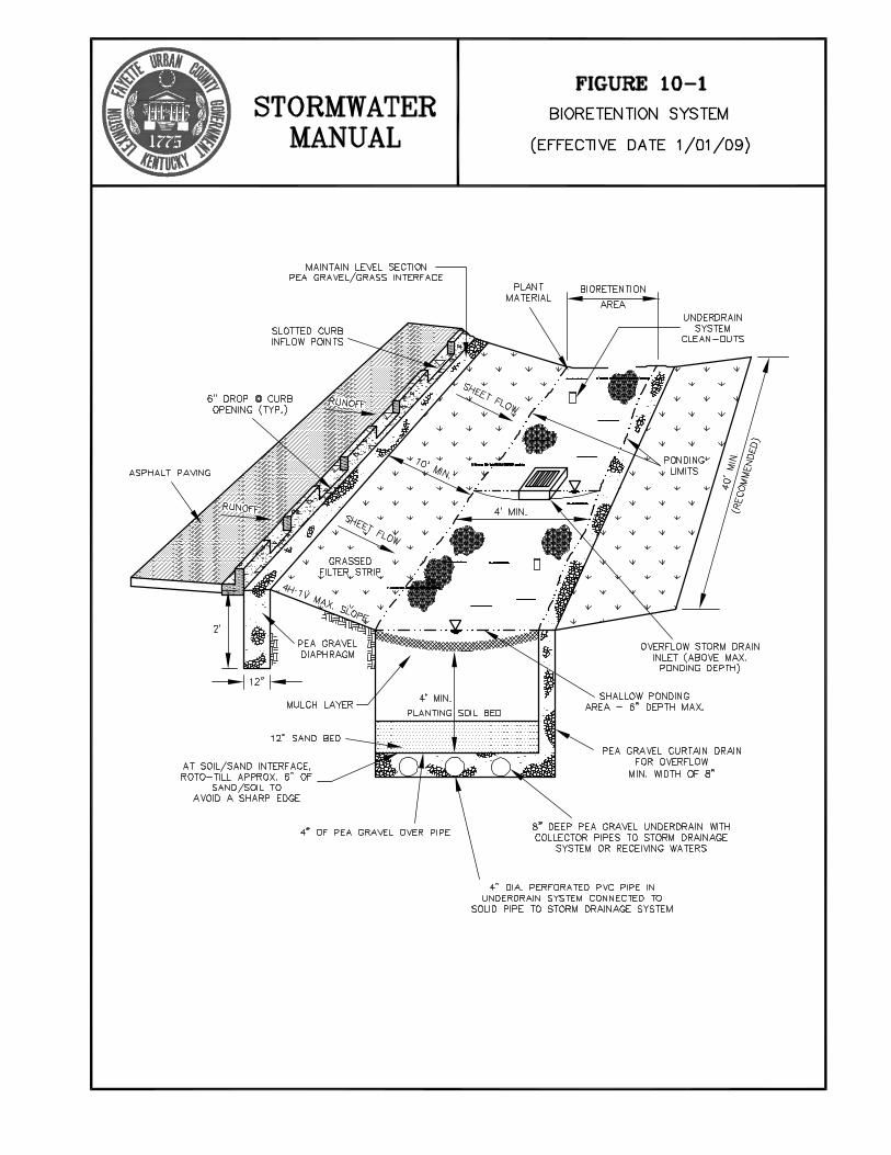
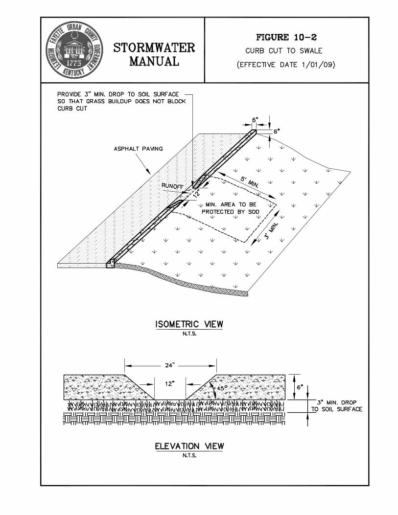
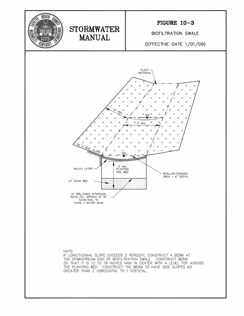


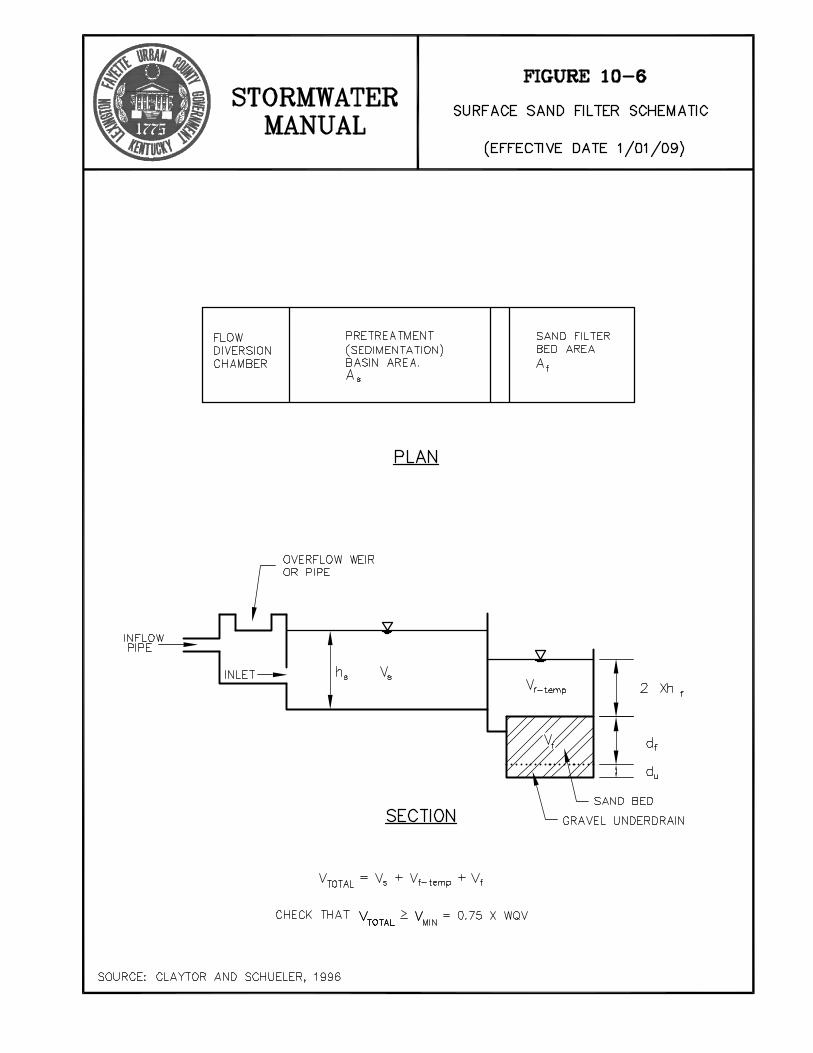
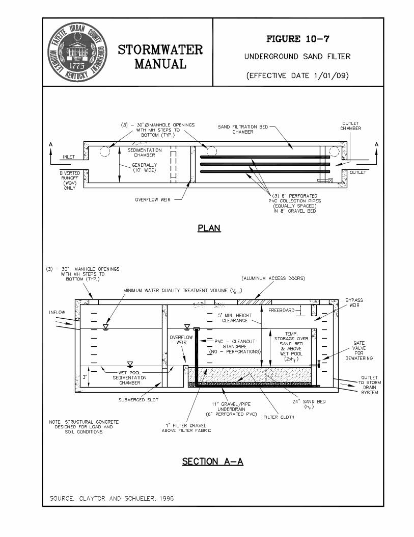
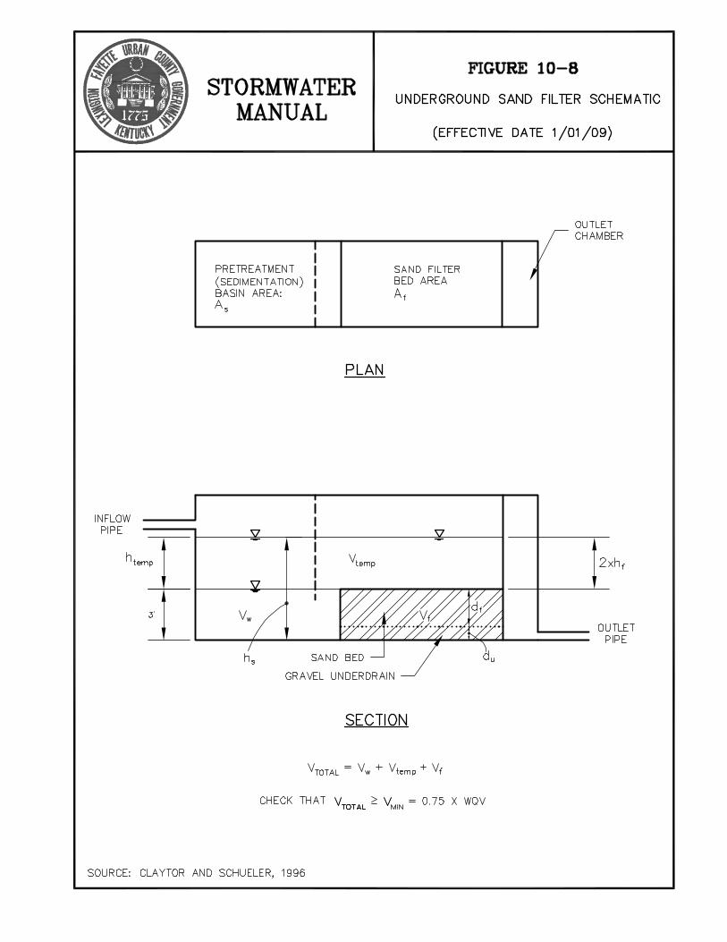
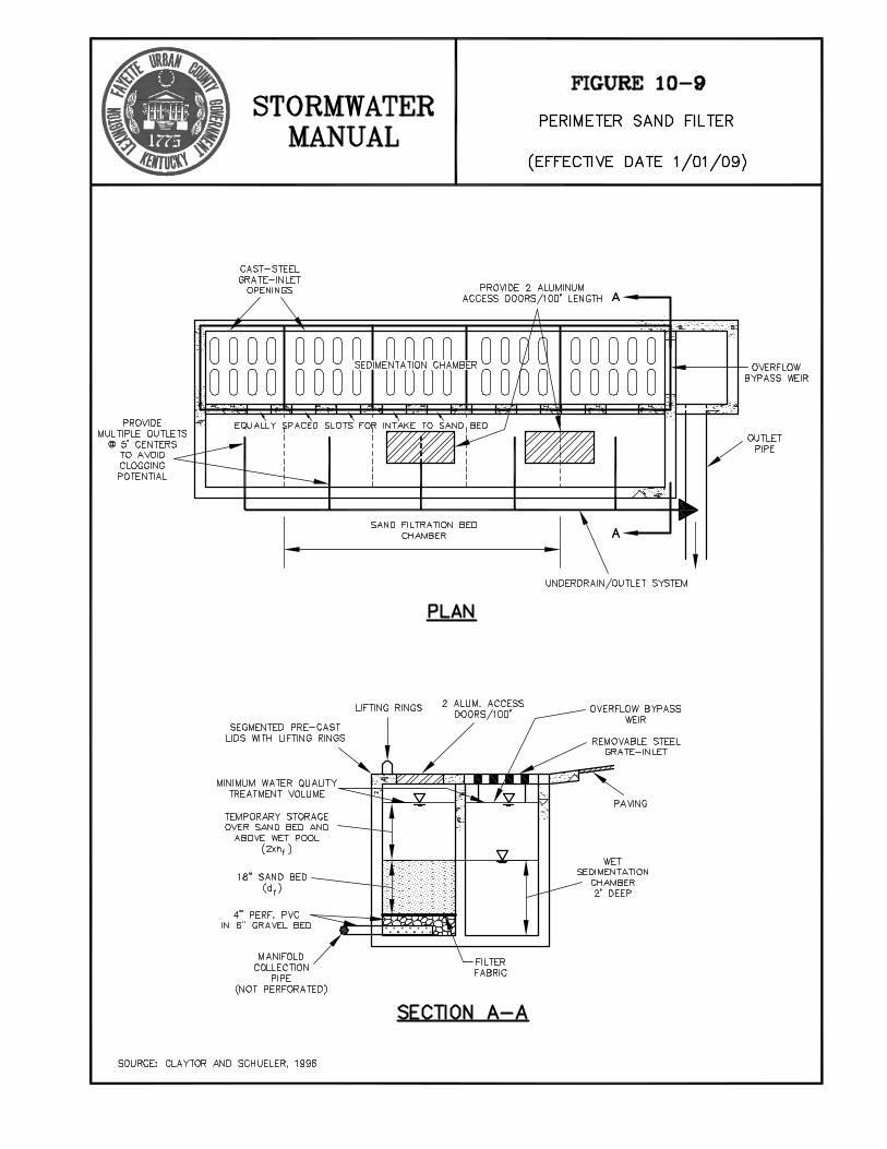

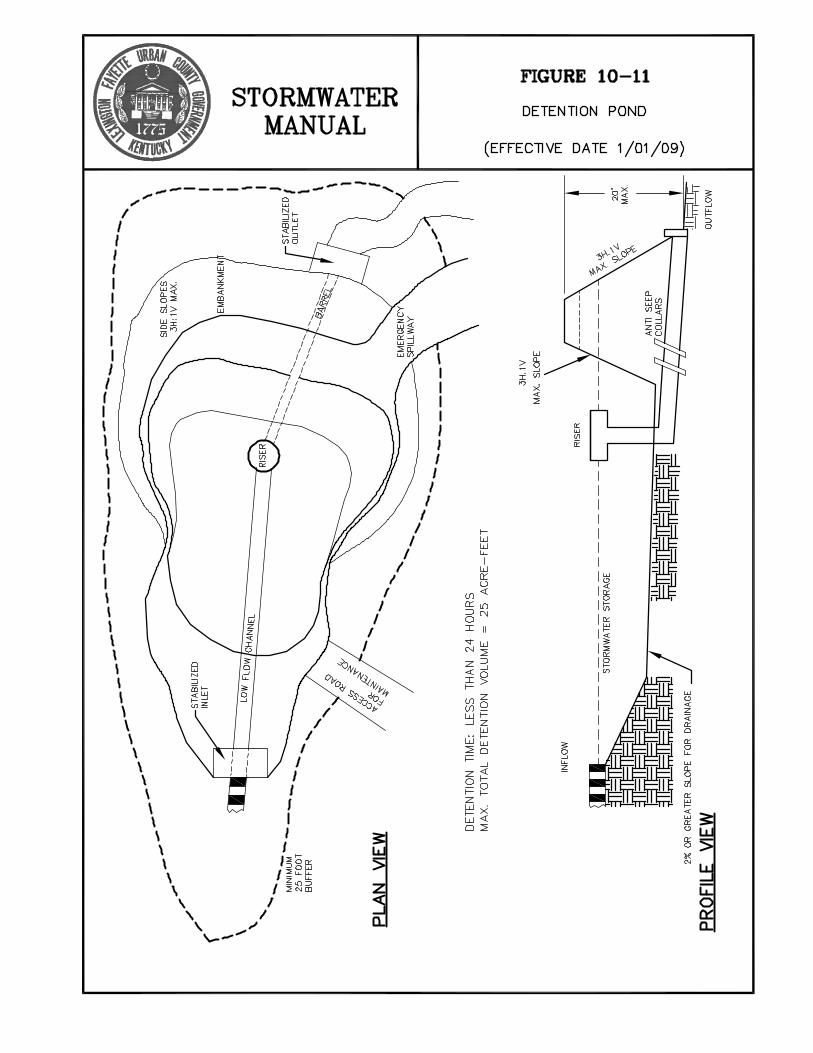

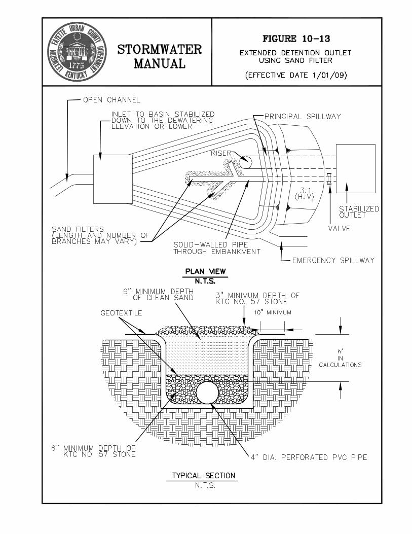
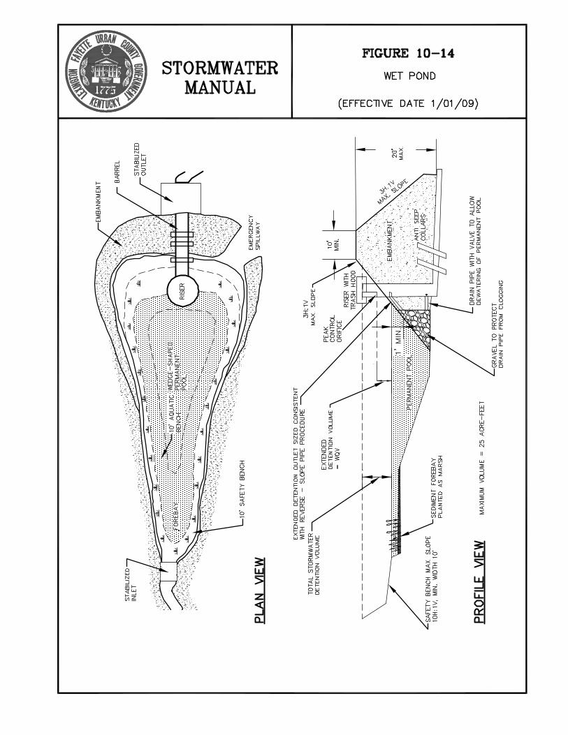
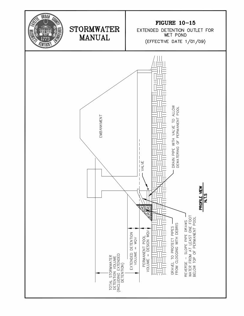

CHAPTER 12 MAINTENANCE MANUAL
FOR STORMWATER BEST MANAGEMENT PRACTICES

STORMWATER MANUAL 12-1 January 1, 2009 LEXINGTON-FAYETTE CO., KY
12.1 Introduction As Fayette County urbanizes, the impact of urbanization on the water resources of the county’s watersheds becomes more apparent. Development has altered stormwater drainage patterns and characteristics, sometimes resulting in flooding. The developed uses of land in the county have resulted in the introduction to the waters of non-desirable substances. These substances are known as nonpoint source pollution and include sediment, nutrients such as phosphorous, motor oil, lawn and garden care products, and anything else that washes from streets and developed property into the county’s streams. Stormwater management efforts in Fayette County have been focused on reducing the risks of downstream flooding. An important tool has been the detention basin, which temporarily stores runoff during large storms and releases it slowly so that peak flows are reduced. In some instances, these detention basins have been combined with amenity ponds or water quality ponds to produce multi-functional ponds. In other instances, water quality ponds with no storage for flood protection have been constructed. In some instances, practices other than ponds have been constructed to mitigate flooding and/or protect water quality. All of these practices are generally referred to as BMPs – Best Management Practices. Fayette County is transitioning from a stormwater management program that only considers flooding to one that considers both flooding and water quality. This transition mandates that more complicated BMPs be installed to control the small storms that occur frequently and impact water quality as opposed to larger, less frequent storms that cause flooding. These BMPs include infiltration areas, wet ponds, sand filters, vegetative swales, oil and grease removal facilities, and constructed wetlands. The water quality practices are inherently more complex, not only in their function and operations, but also in the numbers and types of materials used to construct them. They commonly include natural materials like aquatic vegetation and microorganisms. The increased complexity demands a greater level of maintenance and management to assure safe and effective operation. No two BMPs are the same and their maintenance needs are as different as the BMPs themselves. This requires expertise and judgment to be involved in the BMP maintenance process, thereby requiring a higher level of skill for the majority of the maintenance. This manual for maintaining BMPs has been developed as a part of Lexington’s watershed management program. The manual includes:
• a brief discussion of each BMP • a listing of the mechanisms used to protect water quality • a listing of the maintenance required • a listing of the inspection required • the assigning of responsibility for maintenance between the property owner and the
Lexington-Fayette Urban County Government (LFUCG)

STORMWATER MANUAL 12-2 January 1, 2009 LEXINGTON-FAYETTE CO., KY
The manual also includes a checklist for use in inspection of each practice or type of practice. The completed checklists will be placed in the LFUCG Geographical Information System (GIS) as data tables associated with the location of each BMP.

STORMWATER MANUAL 12-3 January 1, 2009 LEXINGTON-FAYETTE CO., KY
12.2 Dry Detention Pond 12.2.1 Description An area used to detain stormwater for a relatively short period of time to reduce downstream peak discharge rates. The area should go dry between storms. This is the traditional type of detention system used in “drainage” programs for many years to help provide flood protection. Any sediment that collects in the bottom of the basin reduces the capacity for flood control. 12.2.2 Pollutant Removal Mechanisms Settling or sedimentation of larger, heavier particles is the primary mechanism. In some systems, limited infiltration may occur. 12.2.3 Operation, Maintenance, and Inspection Operation Successful operation depends on maintaining the storage volume, the discharge rate, and, in many cases, the system’s infiltration capability. Maintenance Activities necessary to maintain the functioning of a dry detention system include:
• Frequent removal of accumulated solids, debris, and litter from the detention area, especially from the low flow channel; sediments should be removed when they are dry and have cracked, separating from the bottom and vegetation
• Removal of debris from vegetated area to prevent damage to vegetation and to maintain visual appearance
• Removal of debris from the bottom of the pond to reduce clogging of outlet structures, trash racks, and other mechanical components
• Mowing • Removal of vegetation, such as small trees, which can damage the embankment • Vegetative stabilization of eroding sides or bottom
Inspection Inspections are necessary to assure proper discharge, prevention of soggy bottoms, assure healthy vegetative growth, and to monitor accumulation of sediments. Inspections should include the following:
• Obstructions of the inlet or outlet devices by trash and debris • Excessive erosion or sedimentation • Cracking or settling of the dam • Deterioration of pipes • Condition of the emergency spillway • Stability of the side-slopes

STORMWATER MANUAL 12-4 January 1, 2009 LEXINGTON-FAYETTE CO., KY
• Up and downstream channel conditions • Signs of vandalism
12.2.4 Responsibility of Lexington-Fayette Urban County Government (LFUCG)
• Inspect the facility once each year and schedule any appropriate maintenance activities in accordance with the items listed above.
• Conduct all maintenance activities except those of commercial property owner listed below. Removal of deposited sediment is envisioned approximately once every five years.
12.2.5 Responsibility of Commercial Property Owner
• Conduct all required maintenance.

STORMWATER MANUAL 12-5 January 1, 2009 LEXINGTON-FAYETTE CO., KY
12.3 Dry Extended Detention Pond 12.3.1 Description A dry detention system with a discharge structure that is modified to extend the detention time of runoff, typically up to 24 to 48 hours. The modified discharge may also include some type of filtering device (i.e., gravel or sand envelope) to improve the removal of particulate pollutants. Dry extended detention systems may be designed as either on-line or off-line facilities. A dry extended detention pond detains runoff from small, frequent storms and the “first flush” from larger storms in a lower second stage, with a normally dry upper stage for detention of larger storms for flood control. To improve stormwater treatment, the second stage can be designed and managed as a shallow marsh. 12.3.2 Pollutant Removal Mechanisms
• Settling or sedimentation • Plant uptake and bacterial activity in two-stage systems with a shallow marsh • In some systems, limited infiltration may occur.
12.3.3 Operation, Maintenance, and Inspection Operation Successful operation depends on maintaining the storage volume, the discharge rate, and, in many cases, the system’s infiltration capability. Maintenance Activities necessary to maintain the functioning of a dry extended detention system include:
• Frequent removal of accumulated solids, debris, and litter from the detention area, especially the low flow channel if included. Sediments should be removed when they are dry and have cracked, separating from the bottom and vegetation.
• Removal of debris from the control device since it typically will have a small orifice. • Mowing and removal of vegetation. The use of low growing, native grasses is
recommended to minimize mowing frequency and the need for irrigation and fertilizers, which should only be used when necessary.
• Vegetative stabilization of eroding sides or bottom. • Management of aquatic plants if portions of the basin have been designed as a
constructed wetland. Inspection Inspections are necessary monthly and after large storms to assure proper discharge, prevention of soggy bottoms, assure healthy vegetative growth, and to monitor accumulation of sediments. Inspections should include the following:

STORMWATER MANUAL 12-6 January 1, 2009 LEXINGTON-FAYETTE CO., KY
• Obstructions of the inlet or outlet devices by trash and debris • Excessive erosion or sedimentation • Cracking or settling of the dam • Low spots in the bottom of an extended detention facility • Deterioration of pipes • Condition of the emergency spillway • Stability of the side-slopes • Up and downstream channel conditions • Signs of vandalism
12.3.4 Responsibility of Lexington-Fayette Urban County Government (LFUCG)
• Inspect the facility once each year and schedule any appropriate maintenance activities in accordance with the items listed above.
• Conduct all maintenance activities except those of commercial property owner listed below. Removal of deposited sediment is envisioned approximately once every two to five years.
12.3.5 Responsibility of Commercial Property Owner
• Conduct all required maintenance.

STORMWATER MANUAL 12-7 January 1, 2009 LEXINGTON-FAYETTE CO., KY
12.4 Wet Detention Pond 12.4.1 Description A detention system with a permanent pool of water that is completely or partially displaced by stormwater from the contributing drainage area. Water is temporarily stored before it is slowly released. A wet detention system is essentially a small lake with rooted wetland vegetation in the littoral zone. 12.4.2 Pollutant Removal Mechanisms
• Settling or sedimentation • Chemical flocculation, which occurs when heavier sediment particles overtake and
coalesce with smaller, lighter particles to form a still larger particle • Dissolved stormwater pollutants are reduced by a variety of biological processes
including filtering, adsorption onto bottom sediments, uptake by aquatic plants including algae, and metabolism by microorganisms inhabiting bottom sediments and aquatic plants
• Removal of stormwater pollutants primarily occurs during the relatively long quiescent period between storms
12.4.3 Operation, Maintenance, and Inspection Operation Successful operation depends on good design, construction, and maintenance, especially of the discharge structure and littoral zone vegetation. Maintenance Activities necessary to maintain the functioning of wet detention system can be broken down into two categories, routine and corrective. Specific routine maintenance activities include:
• Grass mowing and removal from side slopes and the embankment • Removal of trees, brush, and animal burrows from the embankment • Vegetative cover stabilization to prevent erosion of side slopes and the embankment • Removal and disposal of trash and debris, especially from inlet or outlet structures • Monitoring and periodic removal of nuisance species in the littoral zone • Thinning and transplanting of thriving littoral zone plants as needed to maintain good
growth throughout the littoral zone • Monitoring for mosquitoes and introduction of natural predators as needed • Monitoring of sediment accumulations in forebays or in the pond bottom • Monitoring of channel erosion in downstream conveyances

STORMWATER MANUAL 12-8 January 1, 2009 LEXINGTON-FAYETTE CO., KY
Specific corrective maintenance activities include:
• Pond dewatering and removal of accumulated sediments. The frequency will depend on a variety of factors including use of pretreatment BMPs or forebays, contributing drainage area, land use, sediment loading, etc. A good rule of thumb is to remove sediment when 10 to 20 % of the system’s storage volume has been lost.
• Structural repairs to inlets, outlets, or discharge structure, including the emergency spillway.
• Repairs to the dam, embankment, or slopes to prevent erosion or piping. • Repairs to fences, if applicable.
Inspection Inspections are necessary monthly and after large storms to assure proper discharge, monitor accumulations of trash and debris, monitor sediment accumulations in forebays or inlets, determine mowing or vegetation removal needs, and determine health of littoral zone vegetation. Inspections should include the following:
• Obstructions of the inlet or outlet devices by trash and debris • Excessive erosion or sedimentation • Cracking or settling of the dam • Low spots in the bottom of an extended detention facility • Deterioration of pipes • Condition of the emergency spillway • Stability of the side-slopes • Up and downstream channel conditions • Signs of vandalism
Monitor pond sediment accumulations annually. This can be done by coring, installation of a permanent measuring device such as a “yardstick,” or even by mapping the pond bathymetry in larger ponds. 12.4.4 Responsibility of Lexington-Fayette Urban County Government (LFUCG)
• Inspect the facility once each year and schedule any appropriate maintenance activities in accordance with the items listed above.
• Conduct all maintenance activities except those of commercial property owner listed below. Removal of deposited sediment is envisioned approximately once every five years.
12.4.5 Responsibility of Commercial Property Owner
• Conduct all required maintenance.
STORMWATER MANUAL 12-9 January 1, 2009 LEXINGTON-FAYETTE CO., KY
12.5 Constructed Wetlands 12.5.1 Description A runoff storage and treatment area constructed in uplands that is vegetated with aquatic macrophyte plants native to the area. These systems attempt to incorporate properties of natural wetlands such as shallow, sheet flow through dense, diverse assemblage of wetland plants that also serve as habitat for microorganisms. 12.5.2 Pollutant Removal Mechanisms
• Settling or sedimentation • Adsorption to sediments, vegetation, or detritus • Filtration by plants • Microbial uptake and/or transformations • Uptake by wetland plants or algae • Extended detention • Removal of stormwater pollutants primarily occurs during the relatively long
quiescent period between storms 12.5.3 Operation, Maintenance, and Inspection Operation Successful operation depends on good design, construction, and maintenance, especially of the sediment forebays, wetland vegetation, and the discharge structure. Maintenance Activities necessary to maintain the long term functioning of a constructed wetland system include the following:
• Grass mowing and removal from side slopes and the embankment • Removal of trees, brush, and animal burrows from the embankment • Vegetative cover stabilization to prevent erosion of side slopes and the embankment • Removal and disposal of trash and debris, especially from inlet or outlet structures • Monitoring and periodic removal of nuisance plant and animal species • Thinning and transplanting of thriving wetland plants as needed to maintain good
growth throughout the constructed wetland • Monitoring for mosquitoes • Monitoring and removal of sediment accumulations in forebays or within the
constructed wetland Inspection
• Inspect quarterly and after large storms to assure proper discharge, monitor accumulations of trash and debris, monitor sediment accumulations in forebays or

STORMWATER MANUAL 12-10 January 1, 2009 LEXINGTON-FAYETTE CO., KY
inlets, determine mowing or vegetation removal needs, and determine health of wetland vegetation.
• Closely monitor the wetland plant community, both during the growing season and, if needed, during the dry season, to assure healthy growth of desired plants. Remove exotic or nuisance species as soon as they appear to limit their establishment and areal extent. Thin or transplant plants from areas where they are growing densely and use them to further establishment or growth in areas with less vigorous plant growth.
• Monitor sediment accumulations in forebays semiannually. Sediments should be removed when 25% of the storage volume of the forebay has been lost.
12.5.4 Responsibility of Lexington-Fayette Urban County Government (LFUCG)
• Inspect the facility once each year and schedule any appropriate maintenance activities in accordance with the items listed above.
• Conduct all maintenance activities except those of commercial property owner listed below.
12.5.5 Responsibility of Commercial Property Owner
• Conduct all required maintenance.
STORMWATER MANUAL 12-11 January 1, 2009 LEXINGTON-FAYETTE CO., KY
12.6 Biofiltration Practices 12.6.1 Description Biofiltration is a term used to describe the generally simultaneous processes of filtration, infiltration, adsorption, ion exchange, and biological uptake of pollutants from runoff as it flows through a vegetated stormwater management system. Biofiltration practices include vegetated swales, filter strips, and bioretention areas. Swales are conveyances where the flow passes through vegetation at some specified depth. Filter strips are broad surfaces that receive flow as a well distributed thin sheet. Bioretention practices capture sheet flow from impervious surfaces and treats it by infiltration, filtration, plant uptake, and microbial processes as the runoff flows through native forest or landscaped areas. 12.6.2 Pollutant Removal Mechanisms
• Infiltration, ion exchange, and adsorption • Settling • Vegetative filtration and uptake • Microbial action • The degree to which the various pollutant removal mechanisms operate depends on
soil properties, condition and types of plants, depth, water velocity, slope, and residence time.
12.6.3 Operation, Maintenance, and Inspection Operation Successful operation depends on proper design, especially estimation of hydraulic resistance times and infiltration rates, proper construction and regular maintenance. Maintenance Activities necessary to maintain the functioning of biofiltration practices include:
• Vegetation removal to maintain adequate hydraulic functioning. Biofilter turf grass height should not exceed six inches nor be less than two inches. Excessively long grass can flatten when water flows over it, preventing sedimentation. Additionally, if not removed, decaying vegetation could release captured nutrients and other pollutants.
• Frequent removal of accumulated solids, debris, and litter. Sediments should be removed when they reach 20% of the design depth in any spot, cover or hinder the growth of vegetation, or otherwise interfere with the operation. Maintenance workers should give special attention to sediment accumulation in the upper portion of swales after major storm events. Sediment and large debris should be removed from biofilters at least twice annually and more frequently if needed.
• Vegetative stabilization of eroding sides or bottom or of bare areas created when removing sediments. Fertilizer use should be minimized. Vegetation should be
STORMWATER MANUAL 12-12 January 1, 2009 LEXINGTON-FAYETTE CO., KY
maintained and replanted early enough in the growing season so that it is well established before the rainy season or before the prime growing period ends.
• If swale blocks are used to promote infiltration or sedimentation, special attention needs to be paid to their maintenance. Sediments need to be carefully removed without damaging the swale block or its associated vegetation.
• If curb cuts are used as inflows to biofilters, sediments and vegetation growths should be removed from the curb cut when they begin to interfere with the inflow.
• Roadside shoulder scraping and ditch cleaning should be based on hydraulic necessity, not simply a timed schedule. When these operations are performed, only the amount of sediment to restore hydraulic capacity should be removed. More importantly, the shoulder and swale should be revegetated immediately to minimize erosion and restore treatment effectiveness. Operations should be done in the dry season.
Inspection
• Inspect semiannually and after large storms to assure proper flow, vegetative growth, and to monitor accumulation of sediments, trash, and debris.
12.6.4 Responsibility of Lexington-Fayette Urban County Government (LFUCG)
• Inspect the facility once each year and schedule any appropriate maintenance activities in accordance with the items listed above.
• Conduct all maintenance activities except those of commercial property owner listed below.
12.6.5 Responsibility of Commercial Property Owner
• Conduct all required maintenance.
STORMWATER MANUAL 12-13 January 1, 2009 LEXINGTON-FAYETTE CO., KY
12.7 Infiltration Practices 12.7.1 Description A family of practices in which the “treatment volume” is infiltrated into the soil rather than discharged off-site. Infiltration practices include basins and dry wells. 12.7.2 Pollutant Removal Mechanisms The primary “treatment” mechanism is the infiltration and evaporation of runoff. This reduces the total volume of stormwater leaving the site, thereby reducing the total pollutant loading. Ancillary benefits of reducing stormwater volume include a decrease in stream channel erosion and loss of stream habitat. Pollutant removal occurs as runoff passes through the soil profile and/or the vegetation root mass. Pollutants are trapped, bound, or decomposed in the vegetation, its roots, and in the pore spaces between the soil particles, while runoff passes into the ground. Soils must have an appropriate infiltration rate, contain sufficient organic matter, and maintain aerobic conditions to minimize migration of pollutants into the ground water. 12.7.3 Operation, Maintenance, and Inspection Operation Infiltration practices all depend on the ability of stormwater to pass through the vegetation and soil into the ground. Therefore, long term operation of the practice depends on maintaining its permeability. Maintenance Maintenance activities shall include:
• Removal of accumulated solids • Mowing and removal of vegetation • Vegetative stabilization of eroding sides or bottom • Rototilling, disking, or aerating the bottom or bottom vegetation • Clearing materials that have accumulated in the discharge structure • Cleaning pretreatment BMPs (i.e., swales, sediment sumps) so they can continue to
protect the infiltration practice Inspection
• Inspect the facility semiannually (just before the wet season and at the end of it) and after large storms. If there is still water in the BMP after 72 hours (or after 24-36 hours for vegetated systems), it is time to clean it and restore its percolation capacity. Cleanout frequency will depend on whether the practice is on-line or off-line, vegetated or not vegetated, its design storage capacity, sediment loading, and use of pretreatment BMPs.
• Eroding sides or bottoms shall be revegetated as soon as possible

STORMWATER MANUAL 12-14 January 1, 2009 LEXINGTON-FAYETTE CO., KY
• Revegetate the contributing area where needed to stabilize and reduce generation of particulates
12.7.4 Responsibility of Lexington-Fayette Urban County Government (LFUCG)
• Inspect the facility once each year and schedule any appropriate maintenance activities in accordance with the items listed above.
• Conduct all maintenance activities except those of commercial property owner listed below.
12.7.5 Responsibility of Commercial Property Owner
• Conduct all required maintenance.
STORMWATER MANUAL 12-15 January 1, 2009 LEXINGTON-FAYETTE CO., KY
12.8 Modular Pavement 12.8.1 Description Pavement consisting of strong structural materials having regularly interspersed void areas that are filled with pervious materials such as sand, gravel, or sod. Generally used in low-volume traffic areas such as the outer parts of parking lots or in parking lots serving parks or recreational areas. 12.8.2 Pollutant Removal Mechanisms
• Percolation of rainfall and runoff through the voids into the underlying permeable base and then into the soil
• Filtration of rainfall and runoff by the vegetation that can grow in the voids 12.8.3 Operation, Maintenance, and Inspection Operation Successful operation depends on maintaining the percolation rate of the void spaces and the underlying base and soils. Keys to assuring long-term performance are accurate estimation of the soil’s percolation rate, proper construction, and regular maintenance. Maintenance Activities necessary to maintain the performance of modular pavements include:
• “Good housekeeping” practices by the users to minimize the production and transport of sediment onto the modular pavement. This includes vegetative stabilization of adjacent areas that may erode and become a source of sediments.
• Replacement of base and underlying soils if they become clogged and water ponding persists.
• When turf is incorporated into the installation, normal turf maintenance will be necessary. However, mowing is seldom required in areas of frequent traffic and fertilizers and pesticides should be used sparingly since this may adversely affect concrete products and groundwater.
Inspection
• All modular pavements should be inspected several times in the first few months after construction to assure that they are working correctly and were installed properly. Inspections should be conducted after storms to check for long duration surface ponding that may indicate local or widespread clogging.
12.8.4 Responsibility of Commercial Property Owner
• Conduct all required maintenance.

STORMWATER MANUAL 12-16 January 1, 2009 LEXINGTON-FAYETTE CO., KY
12.9 Stormwater Filters 12.9.1 Description A family of stormwater treatment practices which typically consist of a storage BMP in conjunction with a filtering device. The most common filter media is sand, but filters have been made of peat/sand mixtures and even from leaf compost. 12.9.2 Pollutant Removal Mechanisms
• Settling or sedimentation • Filtration by sand or other filter media • Microbial uptake and/or transformations
12.9.3 Operation, Maintenance, and Inspection Operation Successful operation depends on good design, construction, and most importantly, on regular maintenance, especially of the filter media to prevent clogging. Maintenance Activities necessary to maintain the long term functioning of stormwater filtrations systems include:
• Grass mowing and removal from side slopes and the embankment • Removal of trees, brush, and animal burrows from the embankment • Vegetative cover stabilization to prevent erosion of side slopes and the embankment • Removal and disposal of trash and debris, especially from inlet or outlet structures • Removal of sediments and other materials that accumulate in pretreatment practices,
such as sediment traps and forebays • Periodic scraping and aeration of the filter media, with partial removal
Inspection
• Inspect monthly and after large storms to assure proper discharge, monitor accumulations of trash and debris, monitor sediment, accumulations in forebays or inlets, determine mowing or vegetation removal needs, and determine whether the filter media is clogging.
• Closely monitor clogging of the filter media to determine when maintenance is needed.
• Monitor sediment accumulations in sediment traps semiannually. Sediments should be removed when 25% of the storage volume has been lost.
12.9.4 Responsibility of Commercial Property Owner
• Conduct all required maintenance.

STORMWATER MANUAL 12-17 January 1, 2009 LEXINGTON-FAYETTE CO., KY
12.10 Prefabricated Treatment Devices 12.10.1 Description These BMPs consist of flow-through concrete structures with a settling or separation unit. 12.10.2 Pollutant Removal Mechanisms
• Swirl action • Indirect filtration
12.10.3 Operation, Maintenance, and Inspection Operation Successful operation depends on good design, construction, and, most importantly, on regular cleaning. Maintenance Activities necessary to maintain the long-term functioning of stormwater filtration systems include:
• Removal of sediments and other materials that accumulate in the device Inspection Inspect monthly and after large storms to assure proper operation.

Inspection Checklists

1Lexington-Fayette Urban County Government Operation and Maintenance Inspection Report for Stormwater Management Ponds
BMP Name/GIS Number Subdivision Inspection Name Address Inspection Date Stormwater Pond Normal Pool Normally Dry Watershed
Items Inspected
Checked Maintenance Needed Inspection Frequency
Remarks Yes No Yes No
I, Pond Components A. Embankment and emergency spillway
A,S
1. Vegetation and ground cover adequate
2. Embankment erosion 3. Animal burrows 4. Unauthorized plantings
5. Cracking, bulging, or sliding of dam
a. Upstream face
b. Downstream face c. At or beyond toe
Upstream
Downstream d. Emergency spillway 6. Pond, toe & chimney drains clear and functioning
7. Seeps/leaks on downstream face
8. Slope protection or riprap failures
9. Vertical and horizontal alignment of top of dam as per “As-Built” plans
10. Emergency spillway clear of obstructions and debris
11. Other (specify) B. Riser and principal spillway A Type: Reinforced concrete Corrugated pipe Masonry 1. Low flow orifice obstructed
2. Low flow trash rack a. Debris removal necessary
b. Corrosion control 3. Weir trash rack maintenance a. Debris removal necessary b. Corrosion control 4. Excessive sediment accumulation inside riser
5. Concrete/masonry condition riser and barrels a. Cracks or displacement
Inspection Frequency Key: A = Annual, M = Monthly, S = After major storm

Lexington-Fayette Urban County Government Operation and Maintenance Inspection Report for Stormwater Management Ponds
(continued)
Items Inspected
Checked Maintenance Needed Inspection Frequency
Remarks Yes No Yes No
I, Pond Components b. Minor spalling (< 1”) c. Major spalling (rebars exposed)
d. Joint failures e. Water tightness 6. Metal pipe condition 7. Control valve a. Operational/exercised
b. Chained and locked 8. Pond drain valve
a. Operational/exercised
b. Chained and locked 9. Outfall channels functioning 10. Other (specify) C. Permanent pool (wet pond) M 1. Undesirable vegetative growth 2. Floating or floatable debris removal required
3. Visible pollution 4. Shoreline problems 5. Other (specify) D. Sediment forebays 1. Sedimentation noted 2. Sediment cleanout when depth < 50% design depth
E. Dry pond areas M 1. Vegetation adequate 2. Undesirable vegetative growth 3. Undesirable woody vegetation 4. Low flow channels clear of obstructions
5. Standing water or wet spots 6. Sediment and/or trash accumulation
7. Other (specify) F. Condition of outfalls into pond A,S 1. Riprap failures 2. Slope erosion 3. Storm drain pipes 4. Endwalls/headwalls 5. Other (specify) G. Other M 1. Encroachments on pond or easement area
Inspection Frequency Key: A = Annual, M = Monthly, S = After major storm

2Infiltration Basin Maintenance Inspection Report
Date Time
Project
Location
Individual Conducting the Inspection “As Built” Plans available Y/N
Inspection frequency shown in parentheses after item being considered
Satisfactory Unsatisfactory 1. Debris cleanout (Monthly) Basin bottom clear of debris Inlet clear of debris Outlet clear of debris Emergency spillway clear of debris 2. Sediment traps or forebays (Annual) Obviously trapping sediment greater than 50% of storage volume remaining
3. Vegetation (Monthly) Mowing done when needed Fertilized per specifications No evidence of erosion 4. Dewatering (Monthly) Basin dewaters between storms 5. Sediment cleanout of basin (Annual) No evidence of sedimentation in basin
Sediment accumulation does not yet require cleanout
6. Inlets (Annual) Good condition No evidence of erosion 7. Outlets/overflow spillway (Annual, After Major Storm) Good condition, no need for repair No evidence of erosion 8. Structural repairs (Annual, After Major Storm) Embankment in good repair Side slopes are stable No evidence of erosion 9. Fences/access repairs (Annual) Fences in good condition No damage which would allow undesired entry
Access point in good condition Locks and gate function adequate Inspection Frequency Key Annual, Monthly, After Major Storm

Action to be taken: If any of the answers to the above items are checked unsatisfactory, a time frame shall be established for their correction or repair No action necessary. Continue routine inspections Correct noted facility deficiencies by Facility repairs were indicated and completed. Site reinspection is necessary to verify corrections or improvements. Site reinspection accomplished on Site reinspection was satisfactory. Next routine inspection is scheduled for approximately: Signature of Inspector

3Infiltration Swale Maintenance Inspection Report
Date Time
Project
Location
Individual Conducting the Inspection “As Built” Plans available Y/N
9. Inspection frequency shown in parentheses after item being considered Satisfactory Unsatisfactory 1. Debris cleanout (Monthly) Swales and contributing areas clean of debris
2. Vegetation (Monthly) Mowing done when needed Fertilized per specifications No evidence of erosion Minimum mowing depth not exceeded
3. Dewatering (Monthly) Swale dewaters between storms 4. Check dams or energy dissipators (Annual, After Major Storm) No evidence of flow going around structures
No evidence of erosion at downstream toe
5. Sediment deposition (Annual) Swale clean of sediments 6. Outlets/overflow spillway (Annual, After Major Storm) Good condition, no need for repair No evidence of erosion Inspection Frequency Key Annual, Monthly, After Major Storm
Action to be taken: If any of the answers to the above items are checked unsatisfactory, a time frame shall be established for their correction or repair No action necessary. Continue routine inspections Correct noted facility deficiencies by Facility repairs were indicated and completed. Site reinspection is necessary to verify corrections. Site reinspection accomplished on Site reinspection was satisfactory. Next routine inspection is scheduled for approximately: Signature of Inspector

4Biofiltration Facility Maintenance Inspection Report
Date Time
Project
Location
Individual Conducting the Inspection “As Built” Plans available Y/N
10. Inspection frequency shown in parentheses after item being considered Satisfactory Unsatisfactory 1. Debris cleanout (Monthly) Biofilters and contributing areas clean of debris
No dumping of yard wastes into biofilter
Litter (branches, etc.) have been removed
2. Vegetation (Monthly) Plant height not less than design water depth
Fertilized per specifications No evidence of erosion Grass height not greater than 6 inches
Is plant composition according to approved plans
No placement of inappropriate plants
3. Dewatering (Monthly) Biofilter dewaters between storms No evidence of standing water 4. Check dams or energy dissipators (Annual, After Major Storm) No evidence of sediment buildup Sumps should not be more than 50% full of sediment
No evidence of erosion at downstream toe of drop structures
5. Sediment deposition (Annual) Swale clean of sediments Sediments should not be > than 20% of swale design depth
6. Outlets/overflow spillway (Annual, After Major Storm) Good condition, no need for repair No evidence of erosion No evidence of any blockages 7. Integrity of biofilter (Annual) Biofilter has not been blocked or
filled inappropriately
Inspection Frequency Key Annual, Monthly, After Major Storm

Action to be taken: If any of the answers to the above items are checked unsatisfactory, a time frame shall be established for their correction or repair No action necessary. Continue routine inspections Correct noted facility deficiencies by Facility repairs were indicated and completed. Site reinspection is necessary to verify corrections or improvements. Site reinspection accomplished on Site reinspection was satisfactory. Next routine inspection is scheduled for approximately: Signature of Inspector

5Infiltration Paving Maintenance Inspection Report
Date Time
Project
Location
Individual Conducting the Inspection “As Built” Plans available Y/N
11. Inspection frequency shown in parentheses after item being considered Satisfactory Unsatisfactory 1. Debris on infiltration paving parking area (Monthly) Paving area clean of debris 2. Vegetation (Monthly) Mowing done when needed Fertilized per specifications No evidence of erosion 3. Dewatering (Monthly) Infiltration paving dewaters between storms
4. Sediments (Monthly) Area clean of sediments Area vacuum swept on a periodic basis
5. Structural condition (Annual) No evidence of surface deterioration No evidence of rutting or spalling Inspection Frequency Key Annual, Monthly, After Major Storm
Action to be taken: If any of the answers to the above items are checked unsatisfactory, a time frame shall be established for their correction or repair No action necessary. Continue routine inspections Correct noted facility deficiencies by Facility repairs were indicated and completed. Site reinspection is necessary to verify corrections or improvements. Site reinspection accomplished on Site reinspection was satisfactory. Next routine inspection is scheduled for approximately: Signature of Inspector

6Filtration Facility Maintenance Inspection Report
Date Time
Project
Location
Individual Conducting the Inspection “As Built” Plans available Y/N
12. Warning: If filtration facility has a watertight cover, be careful regarding the possibility of flammable gases within the facility. Care should be taken lighting a match or smoking while inspecting facilities that are not vented.
13. Inspection frequency shown in parentheses after item being considered Satisfactory Unsatisfactory 1. Debris cleanout (Monthly) Contributing areas clean of debris Filtration facility clean of debris Inlets and outlets clear of debris 2. Vegetation (Monthly) Contributing drainage area stabilized
No evidence of erosion Area mowed and clippings removed 3. Oil and grease (Monthly) No evidence of filter surface clogging
Activities in drainage area minimize oil & grease entry
4. Water retention where required (Monthly) Water holding chambers at normal pool
No evidence of leakage 5. Sediment deposition (Annual) Filtration chamber clean of sediments
Water chambers not more than ½ full of sediments
6. Structural components (Annual) No evidence of structural deterioration
Any grates are in good condition No evidence of spalling or cracking of structural parts
7. Outlets/overflow spillway (Annual) Good condition, no need for repair No evidence of erosion (if draining into a natural chamber)
8. Overall function of facility (Annual) No evidence of flow bypassing facility
No noticeable odors outside of facility
Inspection Frequency Key Annual, Monthly, After Major Storm Action to be taken:

If any of the answers to the above items are checked unsatisfactory, a time frame shall be established for their correction or repair No action necessary. Continue routine inspections Correct noted facility deficiencies by Facility repairs were indicated and completed. Site reinspection is necessary to verify corrections or improvements. Site reinspection accomplished on Site reinspection was satisfactory. Next routine inspection is scheduled for approximately: Signature of Inspector

CHAPTER 11
EROSION AND SEDIMENT CONTROL
Revised to be consistent with the new LFUCG ordinance entitled “Reduction of Soil Erosion” in Chapter 16, Article X, Division 5 of the Code of Ordinances; KYR10 permit; and KY BMP Manual

STORMWATER MANUAL 11-i August 29, 2011 LEXINGTON-FAYETTE CO., KY.
TABLE OF CONTENTS
11.1 Purpose ................................................................................................................... 1
11.1.1 Regulatory Basis ............................................................................................... 1
11.2 Requirements .......................................................................................................... 2
11.2.1 Erosion and Sediment Control Plan .................................................................. 2
11.2.2 Non-Structural Practices ................................................................................... 5
11.2.3 Structural Practices for Soil Stabilization ......................................................... 6
11.2.4 Structural Practices for Sediment Control......................................................... 8
11.3 Erosion and Sediment Control Plans .................................................................... 10
11.3.1 Written Description ......................................................................................... 10
11.3.2 Site Map .......................................................................................................... 10
11.3.3 Drawings and Specifications ........................................................................... 11
11.3.4 Design Calculations ........................................................................................ 11
11.3.5 O&M Plan ....................................................................................................... 11
11.3.6 Responsible Parties/Construction Supervisor ................................................. 11
11.3.7 Education/Training .......................................................................................... 11
11.4 Structural Soil Stabilization BMPs ....................................................................... 13
11.4.1 Mulch .............................................................................................................. 13
11.4.2 Temporary Seed .............................................................................................. 15
11.4.3 Permanent Seed ............................................................................................... 16
11.4.4 Sod .................................................................................................................. 18
11.4.5 Road/Parking Stabilization ............................................................................. 21
11.4.6 Construction Entrance ..................................................................................... 22
11.4.7 Dust Control .................................................................................................... 23
11.4.8 Nets and Mats .................................................................................................. 24
11.4.9 Gabion Mattress .............................................................................................. 25
11.4.10 Temporary Diversion Ditch ............................................................................ 27
11.4.11 Level Spreader ................................................................................................ 29
11.4.12 Pipe Slope Drains ............................................................................................ 30
11.4.13 Impact Stilling Basin ....................................................................................... 32
11.5 Structural Sediment Control BMPs ...................................................................... 33
11.5.1 Check Dam ...................................................................................................... 33
11.5.2 Sediment Trap ................................................................................................. 34
11.5.3 Sediment Pond ................................................................................................ 35
11.5.4 Silt Fence ......................................................................................................... 40
11.5.5 Storm Drain Inlet Protection ........................................................................... 42
11.5.6 Filter Strips ...................................................................................................... 43
11.5.7 Temporary Stream Crossing ........................................................................... 46
11.5.8 Pump-Around Flow Diversion ........................................................................ 47
11.5.9 Construction Dewatering ................................................................................ 48
11.5.10 Concrete Washout Pits .................................................................................... 49
11.6 Erosion Control Requirements for Home Builders .............................................. 50

STORMWATER MANUAL 11-1 August 29, 2011 LEXINGTON-FAYETTE CO., KY.
11.1 Purpose
This chapter describes requirements for the planning and implementation of non-structural and structural best management practices (BMPs) to be used for erosion and sediment control during construction activities in Fayette County, Kentucky. Erosion control refers to efforts to maintain soil on a construction site. Sediment control refers to keeping the material that erodes from leaving the site. Sediment leaving a construction site results in the following adverse impacts to the stream environment:
loss of habitat due to decreased light penetration decreases in channel capacity decreases in reservoir storage capacity
Non-structural practices, which are primarily avoidance practices, and structural practices, which require construction, are described in this chapter. A construction site will require the implementation of both types of practices. Details on the structural practices are given in Sections 11.4 and 11.5 of this manual. 11.1.1 Regulatory Basis
Erosion and sediment control on a construction site is regulated by Chapter 16, Article X, Division 5 of the LFUCG Code of Ordinances. Checklists and other information can be found on the LFUCG stormwater webpage.
STORMWATER MANUAL 11-2 August 29, 2011 LEXINGTON-FAYETTE CO., KY.
11.2 Requirements
This section lists the erosion and sediment control requirements. 11.2.1 Permitting Process
Following is a summary of the permitting process for construction sites as described in the LFUCG Code of Ordinances, Chapter 16, Article X, Division 5. Site Disturbance less than 5000 square feet A Land Disturbance Permit is not required for site disturbances less than 5,000 square feet, but the site operator must take reasonable measures to minimize soil erosion. A ten-foot vegetated buffer shall be maintained between the land disturbance activities and the edge of any perennial or intermittent stream, wetland, sinkhole, or municipal storm sewer inlet. If a ten-foot vegetated buffer is not feasible due to the nature or purpose of the activity, a protective alternate erosion control or management practice shall be used. A Land Disturbance Permit is required for new residential or commercial buildings of any size that are not covered under the KYR10 general permit for the common plan of development. The permit application must be submitted to the Division of Engineering. The permit application is on the LFUCG website. Site Disturbance between 5,000 square feet and One Acre A Land Disturbance Permit application must be submitted to the Division of Engineering along with an erosion and sediment control plan for site disturbances between 5,000 square feet and one acre. The permit application and a checklist for preparing the erosion and sediment control plan are on the LFUCG web site. A twenty-five-foot vegetated buffer shall be maintained between the land disturbance activities and the edge of any perennial or intermittent stream, wetland, open throat sinkhole, or municipal storm sewer inlet. Where a twenty-five-foot vegetated buffer is not feasible due to the nature or purpose of the activity, a protective alternate erosion control shall be used as described in the erosion and sediment control plan. In such cases, the permittee shall minimize disturbances in buffer zone areas. In addition, a Land Disturbance Permit is required for new residential or commercial buildings of any size that are not covered under the KYR10 general permit for the common plan of development. The permit application must be submitted to the Division of Engineering. The permit application is on the LFUCG website. Site Disturbance of One Acre and Larger At least 30 days prior to the proposed date of starting construction, the KYR10 Land Disturbance Permit application must be submitted to the Division of Engineering along with a stormwater pollution prevention plan (SWPPP) prepared in accordance with KYR10. The permit application and a checklist for preparing the SWPPP are on the LFUCG website. LFUCG’s permit requirements for sites one acre and larger are the same as the state’s KYR10 general permit with the following exceptions:
STORMWATER MANUAL 11-3 August 29, 2011 LEXINGTON-FAYETTE CO., KY.
1. The limitations on coverage set out in Part I.C. of KYR10 are not applicable. LFUCG will allow permit coverage under KYR10 for all activities subject to Section 16-104 without regard to whether the Kentucky Division of Water requires coverage under an individual KPDES permit in lieu of KYR10. Alternatively, LFUCG will allow permit coverage to be established under an individual permit issued by the Kentucky Division of Water in lieu of KYR10.
2. A SWPPP shall, in addition to satisfying the requirements of KYR10, contain best management practices (“BMPs”) and erosion controls consistent with those described in this manual and Engineering Standard Drawings updated 2008.
3. Inspection reports prepared for all inspections are not required to be certified by a
responsible corporate officer. Inspection reports may be signed by the site operator or the qualified person who conducts the inspection on behalf of the site operator.
4. The requirements for critical areas and buffer zones under KYR10 shall also apply to any municipal storm sewer inlet.
5. The term “as soon as practicable” as used in KYR10 shall mean, for purposes of Section 16-104 and this manual, at the earliest practicable time when external factors beyond the control of the permittee, such as inclement weather, would not prevent completion of the task.
6. Any proposed variances or alternative practices from specific standards that are authorized by KYR10 shall be described in the SWPPP and are subject to review by the Division of Engineering.
7. A SWPPP shall identify any structural water quality control measures that will be retained as part of the post-construction development land use.
8. A SWPPP shall include any special conditions or BMPs required by LFUCG to specifically address streams identified as impaired by sedimentation and/or siltation under Section 303(d) of the Clean Water Act to assure that the discharge is effectively treated to minimize pollution to such impaired water body.
9. A SWPPP shall include any special conditions or BMPs required by the Kentucky Division of Water as KPDES permit conditions to address antidegradation requirements for high quality or exceptional waters.
Linear Utility Line Projects Utility companies that individually disturb less than one acre of land on a regular basis (more than ten times in a year) must submit an Operational Linear Utility Line erosion control plan to the Division of Engineering. Once approved, the Division of Engineering will issue a Linear Utility Line Land Disturbance General Permit with a duration of 24 months.

STORMWATER MANUAL 11-4 August 29, 2011 LEXINGTON-FAYETTE CO., KY.
In addition, the following shall apply:
A Land Disturbance Permit application must be submitted to the Division of Engineering along with an erosion and sediment control plan for an individual project that disturbs 500 linear feet or more of unpaved land surface, but less than one acre, if the project is not covered under an Operational Linear Utility Line erosion control plan.
Individual projects that disturb one or more acres of land must submit a Land Disturbance Permit application to the Division of Engineering.
Utility work that is part of a new development or redevelopment project that disturbs one or more acres of land will be covered by the developer’s KYR10 permit instead of the Linear Utility Line Land Disturbance General Permit.
An erosion control plan is not required for projects that involve the disturbance of 500 linear feet or more of paved land surface and that immediately places all excavated materials into a truck or other transportable soil containment device.
A twenty-five-foot vegetated buffer shall be maintained between the land disturbance activities and the edge of any perennial or intermittent stream, wetland, open throat sinkhole, or municipal storm sewer inlet. Where a twenty-five-foot vegetated buffer is not feasible due to the nature or purpose of the activity, a protective alternate erosion control shall be used as described in the linear utility line erosion control plan. In such cases, the permittee shall minimize disturbances in buffer zone areas.
Inspection and Notification Requirements The permittee shall make regular inspections of all control measures. Regular inspections means at least once every seven calendar days, or at least once every fourteen calendar days and within twenty-four hours after any storm event of one-half-inch or greater. The purpose of such inspections will be to determine the overall effectiveness of the erosion control plan and the need for maintenance and/or additional control measures. Records shall be maintained of each inspection that include:
the date of the inspection the name of the inspector the findings from the inspection any actions taken as a result of the inspection
Records shall be retained for 180 days following termination of the permit after project completion and shall be available for inspection consistent with subsection 16-207(c). For Land Disturbance Permits, the permittee shall notify the Division of Engineering and the Division of Water Quality in writing (email, fax, or letter) at least two working days before the start of construction and at least two working days before the completion of soil stabilization. For utility line projects, the permittee shall notify the Division of Engineering and the Division of Water Quality in writing (email, fax, or letter) at least two working days prior to commencing construction on a project that will result in a disturbance of 500 linear feet or more of existing land surface.
STORMWATER MANUAL 11-5 August 29, 2011 LEXINGTON-FAYETTE CO., KY.
11.2.2 Non-Structural Practices
This section describes the planning and implementation of the required non-structural BMPs to minimize erosion and off-site sedimentation. These BMPs include:
floodplain avoidance stream buffer zones reduced exposure time limits on maximum disturbed area embankment slope minimization
Floodplain Avoidance
No construction or grading activities are permitted in the post-development floodplains, as defined in Chapter 1 of this manual, except for road and utility crossings and permanent stormwater management facilities. Therefore, only erosion and sediment control practices related to allowable construction activities shall be permitted in the post-development floodplain. Temporary sediment control in a permanent pond shall be allowed in the post-development floodplain but not in a stream. Vegetative Buffer Strips
Buffer strips are required adjacent to all streams and wetlands in Fayette County. The buffer strip width shall be 25 feet from the top of each bank and from the edge of a wetland. No grading or land clearing is allowed within the buffer zone, and native vegetation must be preserved. Reduced Exposure Time
All on-site measures required by the Erosion and Sediment Control Plan shall be made functional before other land disturbance takes place. Permanent or temporary soil stabilization, as described under structural practices, shall be applied to disturbed or constructed areas within 14 days after final grade is reached. Soil stabilization shall also be applied to all disturbed areas not at final grade, including soil stockpiles, dams, dikes, and diversions, which have been inactive for 14 days. Limits on Maximum Disturbed Area
The maximum area that may be disturbed at any time during construction, without soil stabilization, is 25 acres. For sites over 25 acres in size, additional land can be disturbed only when an equal amount of land is stabilized. A construction site shall not be broken into individual permits to avoid this requirement. Embankment Slope Minimization
Steep embankment slopes present increased opportunities for erosion and sediment production due to high runoff velocities. To minimize adverse effects of steep embankment slopes, constructed fill slopes and cut slopes shall not be steeper than 3H:1V. For slopes of 4H:1V or steeper with slope lengths of greater than 100 feet, temporary diversion ditches shall be constructed at the top of the slope and every 100 feet horizontally down the slope.

STORMWATER MANUAL 11-6 August 29, 2011 LEXINGTON-FAYETTE CO., KY.
11.2.3 Structural Practices for Soil Stabilization
This section describes the planning and implementation of the required structural BMPs to minimize erosion and off-site sedimentation through the stabilization of soil materials. The BMPs include:
mulch temporary seed permanent seed sod road/parking stabilization construction entrance dust control nets and mats gabion mattress temporary diversion ditch level spreader permanent constructed waterway pipe slope drain impact stilling basin
Mulch
Mulch shall be used as a soil stabilization measure for any disturbed area inactive for 14 days or longer. Areas requiring stabilization during December through February shall receive only mulch held in place with bituminous material. Mulching shall be used whenever permanent or temporary seeding is used. The anchoring of mulch shall be in accordance with Figure 11-1 except all mulch placed in December through February shall be anchored with bituminous materials regardless of the slope. Permanent mulches shall be used in conjunction with planting trees, shrubs, and other ground covers that do not provide adequate soil stabilization. Temporary Seed
Temporary seeding shall be used for soil stabilization when grades are not ready for permanent seeding, except during December through February. The seed shall be applied within 14 days after grading has stopped. Only rye grain or annual rye grass seed shall be used for temporary seeding. The use of mulch and erosion matting and netting with temporary seeding shall be in accordance with Figure 11-1. Permanent Seed
Permanent seeding shall be applied within 14 days after final grade has been reached, except during December through February. Permanent seeding shall also be applied on any areas that will not be disturbed again for a year even if final grades have not been reached. The use of mulch and erosion matting and netting with permanent seeding shall be in accordance with

STORMWATER MANUAL 11-7 August 29, 2011 LEXINGTON-FAYETTE CO., KY.
Figure 11-1. “Seed mats” may be used for permanent seeding in accordance with manufacturers’ recommendations. Sod
Sod shall be used for disturbed areas that require immediate vegetative cover, e.g. the area surrounding a drop inlet in a grassed waterway, the design flow perimeter of a grassed waterway that will convey flow before vegetation can be established, and the inlet of a culvert. Sod may be installed throughout the year. “Seed mats” and seed with geotextiles may be used in place of sod when done in accordance with manufacturers’ recommendations. Road/Parking Stabilization
Gravel or paved material shall be used to stabilize permanent roads or parking areas or roads or parking areas used repeatedly by construction traffic. Stabilization shall be accomplished within 14 days of grading or initiation of use for construction traffic. Unstabilized roads are not acceptable except in instances where the road will be used less than one month. Construction Entrance
A stabilized construction entrance shall be constructed wherever vehicles are leaving a construction site to enter a public road or at any unpaved entrance/exit location where there is a risk of transporting mud or sediment onto paved roads. A construction entrance shall be constructed at the beginning of the project before construction traffic begins to enter and exit the site. Dust Control
Dust control measures shall be implemented on all sites. Nets and Mats
Mulch netting, erosion control matting, or turf reinforcement matting (TRM) shall be used on sloping areas as indicated in Figure 11-1. Mats or nets and permanent seeding may be used as an alternate to sod for culvert entrances and grassed waterways. TRMs shall be used at the water line to control wave action in wet ponds. TRMs shall be used in accordance with manufacturer’s recommendations. Gabion Mattress
Gabion mattresses shall be used at the outlets of all culverts and storm drains with an exit velocity greater than 5 feet per second when flowing full, except where there are paved ditches. Gabion mattresses shall also be used at the outlet of impact stilling basins. Temporary Diversion Ditch
Temporary diversion ditches shall be used to collect sediment-laden runoff from disturbed areas and direct it to a sediment pond where applicable. Temporary ditches are those expected to be in use for less than one year. Temporary diversion ditches do not require stabilization.

STORMWATER MANUAL 11-8 August 29, 2011 LEXINGTON-FAYETTE CO., KY.
Level Spreader
Level spreaders shall be constructed at the outlets of temporary diversion ditches. Level spreaders shall also be constructed at outlets of permanent constructed waterways where they terminate on undisturbed areas. Permanent Constructed Waterway
Permanent constructed waterways shall be used to divert stormwater runoff from upland undisturbed areas around or away from areas to be disturbed during construction. A waterway expected to be in place for at least one year shall be considered permanent. Permanent waterways shall be lined with sod or permanent seeding and nets, mats, or TRMs. Design permanent constructed waterways in accordance with procedures and criteria given in Chapter 8. Pipe Slope Drain
Pipe slope drains shall be used whenever it is necessary to convey water down a steep slope, which is not stabilized or which is prone to erosion, unless paved ditch (flume) is installed. Impact Stilling Basin
Impact stilling basins shall be used at the outlet of culverts and storm sewers with calculated exit velocities greater than 15 feet per second when flowing full. 11.2.4 Structural Practices for Sediment Control
This section describes when and where specific structural sediment control practices are required. The practices include:
check dam sediment trap sediment pond silt fence storm drain inlet protection filter strip stream crossing pump-around flow diversion construction dewatering
Check Dam
Check dams shall be installed in newly-constructed, vegetated, open channels, which drain 10 acres or less. Check dams shall be constructed prior to the establishment of vegetation. Sediment Trap
Sediment traps shall be installed below all disturbed areas of less than 5 acres that do not drain to a sediment pond. Sediment Pond
A sediment pond shall be installed at the outlet of a disturbed area of 5 acres or more. The maximum drainage area for a single pond is 100 acres. The pond shall be designed to reduce
STORMWATER MANUAL 11-9 August 29, 2011 LEXINGTON-FAYETTE CO., KY.
peak discharges during construction to pre-development levels for 10-year and 100-year storms. Silt Fence
Silt fence shall be installed down-slope of areas to be disturbed prior to clearing and grading. Silt fence must be situated such that the total area draining to the fence is not greater than one-fourth acre per 100 feet of fence. Silt fence shall be used for storm drain drop inlet protection and around soil stockpiles. Storm Drain Inlet Protection
Storm drain inlet protection shall only be used around drop inlets when the up-slope area draining to the inlet has no other sediment control. Filter Strip
Filter strips shall be used on each side of permanent constructed channels. The buffer strips described in Section 11.2.2 satisfy the filter strip requirement for streams and wetlands. Stream Crossing
Stream crossings shall be used in cases where construction traffic, permanent traffic, or utilities must cross existing post development floodplains. If the drainage area exceeds 1 square mile and a structure is necessary, the structure must be designed by a professional engineer licensed in Kentucky. If applicable, U.S. Army Corps of Engineers and the Kentucky Division of Water permits, as indicated in Chapter 2 of this manual, may be required. Pump-Around Flow Diversion
A pump-around flow diversion shall be used to divert flow around construction activities occurring in a stream when those activities are reasonably expected to cause the erosion or deposition of sediment in the stream. Construction Dewatering
Sediment-laden water must be pumped to a dewatering structure before it is discharged offsite. Concrete Washout Pits
Concrete washout pits shall be constructed and maintained by the Developer throughout the home building phase of residential development projects. A minimum of one pit per 40 lots shall be constructed prior to plat recording.

STORMWATER MANUAL 11-10 August 29, 2011 LEXINGTON-FAYETTE CO., KY.
11.3 Erosion and Sediment Control Plans (for sites less than one acre)
An erosion and sediment control plan shall be submitted to the Division of Engineering along with a Land Disturbance Permit application for any proposed land disturbance greater than 5,000 square feet and less than 1 acre. In addition, an erosion and sediment control plan shall be submitted to the Division of Engineering along with a Land Disturbance Permit application for a proposed residential or commercial building if the site is not covered under KYR10 as part of the larger common plan of development. For sites one acre and larger, a Stormwater Pollution Prevention Plan must be prepared in accordance with KYR10. The erosion and sediment control plan shall include the items described in the following sub-sections. 11.3.1 Written Description
The erosion and sediment control plan must contain a written description that shall include, at a minimum:
1. A discussion of the land disturbing project including the purpose, location, and size of the area to be disturbed
2. A discussion of the topography, land cover conditions, soils, percent of impervious areas, and drainage patterns both before and after land disturbance
3. An identification of land use and cover conditions of adjacent property
4. A schedule of the work to be conducted including the projected beginning and completion dates of construction activities, and construction sequencing, including clearing, grading, and revegetation activities, as well as any winter shut-downs
5. A listing of erosion and sediment control best management practices, along with location, installation schedule, and the rationale for each use, such as silt fences, diversion ditches, earthen berms, grass strips, or other methods installed in conformance with this manual to prevent, to the maximum extent practicable, sediment from washing into streets, catch basins, storm sewers, grassed open channels, or adjacent seeded or sodded lots
6. A listing of stormwater pollution control and best management practices to minimize pollution during construction (other than erosion) that might result from construction activities
7. A discussion of the permittee’s inspection and maintenance activities for erosion and sediment control best management practices
11.3.2 Site Map
The erosion and sediment control plan must contain a site map showing:
Areas of proposed disturbance

STORMWATER MANUAL 11-11 August 29, 2011 LEXINGTON-FAYETTE CO., KY.
Locations of proposed controls, utilities, paved areas, and construction entrances All perennial or intermittent streams, wetlands, sinkholes, retention basins, retention
ponds, culverts, and storm sewer inlets within one hundred feet of the site Current topography from field surveys or aerial photography at a scale of 1”=50’ with
2-foot contours showing pre-construction topography, property lines, utilities, limits of construction, and trees to be preserved
Finished grades, building locations, paved areas, construction entrances, access or haul roads, stockpile areas, and equipment storage areas overlaid on the site topographic map
Riparian areas and karst features All planned BMPs overlaid on the other features Areas that are not to be disturbed
11.3.3 Drawings and Specifications
Drawings and specifications of the BMPs shall be included in the plan. 11.3.4 Design Calculations
All hydrologic, hydraulic, structural, and geotechnical design calculations shall be included in the plan. 11.3.5 O&M Plan
An operation and maintenance (O & M) plan shall be developed which provides a schedule for inspection, maintenance, and repair of BMPs during construction activities. A maintenance schedule shall also be provided to ensure that permanent measures such as vegetation are properly established after construction is complete. 11.3.6 Responsible Parties/Construction Supervisor
The name, address, and telephone number of the parties responsible for implementing the plan shall be included in the plan. The name of the construction supervisor who will be on-site during construction shall be included in the plan. An on-site construction progress meeting to review erosion prevention and sediment control measures shall be held once the pipe crews have installed the pipe work. The meeting shall be attended by appropriate LFUCG staff, the Engineer, and Contractor. The construction supervisor shall ensure that orange safety fence is placed around each storm sewer manhole and sanitary sewer manhole prior to plat recording to minimize the risk of accidental damage to the manholes. The safety fence may be removed after permanent seeding and sodding has been completed. 11.3.7 Education/Training

STORMWATER MANUAL 11-12 August 29, 2011 LEXINGTON-FAYETTE CO., KY.
The education and training requirements for implementation of the plan shall be accomplished by the Engineer, who shall provide for initial training and continuing education for all construction employees and subcontractors of the contractor to inform them of the plan requirements. As work progresses and various subcontractors and/or new employees are brought onto the work site, each should be familiarized by the Engineer with the plan. At the beginning of each workweek, scheduled items of the plan to be implemented during that week should be brought to the attention of the impacted work force.
STORMWATER MANUAL 11-13 August 29, 2011 LEXINGTON-FAYETTE CO., KY.
11.4 Structural Soil Stabilization BMPs
11.4.1 Mulch
Spreading mulch is a temporary soil stabilization or erosion control practice where materials such as straw, wood chips, wood fibers, or rock are placed on the soil surface. Mulching prevents erosion by protecting the soil surface from raindrop impact and by reducing the velocity of overland flow. Mulch can also be used for dust control. When used with temporary or permanent seeding, mulch can aid in plant growth by holding the seeds, fertilizers, and topsoil in place, by helping to retain moisture, and by insulating against extreme temperatures. Mulch can also improve the aesthetics of the site. Organic mulch materials such as straw, wood chips, bark, recycled paper, and wood fiber are the most effective mulches. Design Criteria
Straw is the mulch most commonly used in conjunction with seeding. The recommended straw should come from wheat, rye, or barley and may be spread by hand or machine. Straw shall be anchored. Wood chips are suitable for areas that will not be closely mowed, and around ornamental plantings. Chips decompose slowly and do not require tacking. Wood chips should be treated with 12 pounds slow-release nitrogen per ton to prevent nutrient deficiency in plants. Bark chips and shredded bark are used in landscaped plantings. Bark is also suitable mulch for areas planted to grasses and not closely mowed. Bark is not usually toxic to grasses or legumes, and additional nitrogen fertilizer is not required. Manufactured wood fiber and recycled paper sold as mulch materials are usually marketed to apply in a hydroseeder slurry with binder/tackifiers. Manufacturer’s recommendations shall be followed during application. A wide range of synthetic, spray-on materials is marketed to stabilize and protect the soil surface. These are emulsions or dispersions of vinyl compounds, asphalt, rubber, or other substances that are mixed with water and applied to the soil. They may be used to tack wood fiber hydromulches or straw, and they usually decompose in 60 to 90 days. A variety of mulch nets and mats are available to use as mulching or to hold mulch in place. Netting and mats shall be used in critical areas such as waterways where concentrated flows are expected. Netting can help retain soil moisture or modify temperature. It stabilizes the soil surface while grasses are being established and is particularly useful in grassed waterways and on slopes. Lightweight netting may also be used to hold other mulches in place. Netting and erosion control mats shall be used in accordance with Figure 11-1. Gravel or crushed stone can be used to provide a long-term protection against erosion, particularly on short slopes. Before the gravel or crushed stone is applied, it should be
STORMWATER MANUAL 11-14 August 29, 2011 LEXINGTON-FAYETTE CO., KY.
washed. Aggregate cover shall only be used in relatively small areas and shall be incorporated into an overall landscaping plan. Material Specifications
Straw shall be applied at two tons per acre or 90 pounds per 1,000 square feet. Straw shall be free from weeds and coarse matter. Wood chips shall be applied at 40 cubic yards per acre or 1 cubic yard per 1,000 square feet and approximately 2 inches deep. Wood chips shall be treated with 20 pounds of nitrogen per acre. Recycled paper (newsprint) or wood fiber shall be mixed at 50 pounds per 100 gallons of water and applied according to manufacturer’s recommendations and model of hydroseeder in use. Bark chips or shredded bark shall be applied at 70 cubic yards per acre or 1.5 to 2 cubic yards per 1,000 square feet and about one-half inch thick. Liquid mulch binders/tackifiers may be asphalt, synthetic, or wood fiber slurries applied according to manufacturer’s recommendations. Chemical soil stabilizers or soil binders/tackifiers/emulsions shall not be used alone. These materials are useful to bind organic mulches together. Construction Specifications
Seed shall be applied prior to mulching except where seed is to be applied as part of a hydroseeder slurry containing mulch. Lime and fertilizer shall be incorporated and surface roughening accomplished as needed prior to mulching in accordance with applicable sections of this manual. Mulch materials shall be spread uniformly by hand or machine. Mulch shall be anchored during or immediately after spreading to prevent being blown by the wind. Mulch may be anchored using a mulch anchoring tool, a liquid binder/tackifier, or mulch nettings. Nets and mats shall be installed to obtain firm, continuous contact between the material and the soil. Without such contact, the material is useless and erosion occurs. A mulch anchoring tool is a tractor-drawn implement that is typically used for anchoring straw and is designed to punch mulch approximately two inches into the soil surface. Machinery shall be operated on the contour and shall not be used on slopes steeper than 3H:1V. When using liquid mulch binders and tackifiers, application shall be heaviest around edges of areas and at crests of ridges and banks to prevent wind blow. Remainder of area shall have binders/tackifiers spread uniformly in accordance with manufacturer’s recommendations.

STORMWATER MANUAL 11-15 August 29, 2011 LEXINGTON-FAYETTE CO., KY.
When using a mulch net, it shall be used in conjunction with an organic mulch and shall be installed immediately after the application and spreading of the mulch. Mulch net shall be installed over the mulch except when the mulch manufacturer recommends otherwise. Excelsior blankets and mats with mulch are considered protective mulches and may be used alone on erodible soils and during all times of year. Erosion control mats shall be installed in accordance with manufacturer’s recommendations. Maintenance
Mulched areas shall be inspected at least weekly and after every rainfall of one-half inch or more. When mulch material is found to be loosened or removed, the mulch cover shall be replaced within 48 hours. 11.4.2 Temporary Seed
Temporary seeding stabilizes disturbed areas by the establishment of a temporary vegetative cover of rapidly growing plants on disturbed areas that are not at final grade. Temporary seeding reduces problems associated with mud or dust from bare soil surfaces during construction, reduces erosion and sediment runoff to downstream areas and/or groundwater basins, and improves the visual appearance of the construction area. Seed, fertilizer, and mulch specifications are listed in the KY Erosion Prevention and Sediment Control Field Guide. Construction Specifications
The site shall be graded as needed to permit the use of conventional equipment for seedbed preparation, seeding, mulch application, and anchoring. The needed erosion control practices shall be installed prior to seeding such as diversions, temporary waterways for diversion outlets, and sediment ponds. Prior to seeding, work the lime and fertilizer into the soil with a disk harrow, springtooth harrow, or similar tools to a depth of two inches. On sloping areas, the final operation shall be on the contour. The seed shall be applied uniformly with a cyclone seeder, drill, cultipacker, seeder, or hydroseeder (slurry may include seed and fertilizer) preferably on a firm, moist seedbed. Seed no deeper than one-fourth inch to one-half inch. When feasible, except where a cultipacker type seeder is used, the seedbed shall be firmed following seeding operations with a cultipacker, roller, or light drag. On sloping land, seeding operations shall be on the contour wherever possible. Mulch shall be applied, in the amounts described in the mulch practice in this chapter, to protect the soil and provide a better environment for plant growth.

STORMWATER MANUAL 11-16 August 29, 2011 LEXINGTON-FAYETTE CO., KY.
The mulch shall be spread uniformly by hand or mechanically so the soil surface is covered. Following application, the mulch shall be anchored or otherwise secured to the ground according to one of the following methods:
Mechanical – Use a disk, crimper, or similar type tool set straight to punch or anchor the mulch material into the soil.
Mulch Tackifiers/Nettings/Emulsions – Use according to the manufacturer’s recommendations. This is a superior method in areas of water concentration to hold mulch in place.
Wood Fiber – Wood fiber hydroseeder slurries may be used to tack straw mulch. This combination treatment is well suited to steep slopes and critical areas, and severe climate conditions.
For more information on mulch application see Section 11.4.1– Mulch. Maintenance
New seed shall have adequate water for growth, through either natural means or irrigation, until plants are firmly established. Seeded areas shall be inspected every two weeks after planting and after each rainfall of 0.5 inches or more. Areas requiring additional seed and mulch shall be repaired within 48 hours. If vegetative cover is not established within 21 days, the area shall be reseeded. 11.4.3 Permanent Seed
Permanent seeding is the stabilization of disturbed areas with the establishment of permanent vegetation by planting seed. The primary purpose of permanent seeding is to permanently stabilize disturbed areas in a manner that is economical, adaptable to site conditions, and allows selection of the most appropriate plant materials. Permanent seeding also reduces the erosion and sediment yield from disturbed areas while the vegetation is becoming established. Design Criteria
Permanent seeding shall be used on disturbed areas where permanent, long-lived vegetative cover is needed to stabilize the soil and on rough graded areas that will not be brought to final grade for one year or more. The area to be seeded shall be protected from excess runoff as necessary with diversions, grassed waterways, terraces, or sediment ponds. Plant species shall be selected on the basis of timing of establishment, planned use of the area, and the amount or degree of maintenance that can be devoted to the area in the future. Vegetative cover alone shall not be used to provide erosion control cover and prevent soil slippage on a soil that is not stable due to its structure, water movement, or excessive slope.

STORMWATER MANUAL 11-17 August 29, 2011 LEXINGTON-FAYETTE CO., KY.
Material Specifications
Seed shall be applied in a mixture based upon the season and ultimate use of the site. Erosion and sediment control plans submitted to LFUCG shall include seed mixtures, rates, and planting dates selected for permanent seeding. Permanent seeding may be done at any time except December through February. Seed, fertilizer, and mulch specifications are listed in the KY Erosion Prevention and Sediment Control Field Guide. Soil material shall be capable of supporting permanent vegetation and have at least 25 percent silt and clay to provide an adequate amount of moisture holding capacity. An excessive amount of sand will not consistently provide sufficient moisture for good growth regardless of other soil factors. Construction Specifications
During site preparation, topsoil shall be stockpiled for use in establishing permanent vegetation. The site shall be graded as needed to permit the use of conventional equipment for seedbed preparation, seeding, mulch application, and anchoring. The needed erosion control practices shall be installed prior to seeding such as diversions, temporary waterways for diversion outlets, and sediment ponds. Prior to seeding, work the lime and fertilizer into the soil with a disk harrow, springtooth harrow, or similar tools to a depth of four inches. On sloping areas, the final operation shall be on the contour. Where compacted soils occur, they should be broken up sufficiently to create a favorable rooting depth of six to eight inches. The seed shall be applied uniformly with a cyclone seeder, drill, cultipacker, seeder, or hydroseeder (slurry may include seed and fertilizer) preferably on a firm, moist seedbed. Seed no deeper than one-fourth inch to one-half inch. When feasible, except where a cultipacker type seeder is used, the seedbed shall be firmed following seeding operations with a cultipacker, roller, or light drag. On sloping land, seeding operations shall be on the contour wherever possible. Mulch shall be applied to protect the soil and provide a better environment for plant growth. The mulch shall be spread uniformly by hand or mechanically so the soil surface is covered. Following application, the mulch shall be anchored or otherwise secured to the ground according to one of the following methods:
Mechanical – Use a disk, crimper, or similar type tool set straight to punch or anchor the mulch material into the soil.
STORMWATER MANUAL 11-18 August 29, 2011 LEXINGTON-FAYETTE CO., KY.
Mulch Tackifiers/Nettings/Emulsions – Use according to the manufacturer’s recommendations. This is a superior method in areas of water concentration to hold mulch in place.
Wood Fiber – Wood fiber hydroseeder slurries may be used to tack straw mulch. This combination treatment is well suited to steep slopes and critical areas, and severe climate conditions.
For more detailed information on mulch application, see Section 11.4.1- Mulch. Maintenance
New seed shall have adequate water for growth, through either natural means or irrigation, until plants are firmly established. Seeded areas shall be inspected every two weeks after planting and after each rainfall of 0.5 inches or more. Areas requiring additional seed and mulch shall be repaired within 48 hours. If vegetative cover is not established within 21 days, the area shall be reseeded. If less than 70 percent groundcover is established, seed and fertilize, using half of rates originally applied, and mulch. If less than 40 percent groundcover occurs, follow original seedbed preparation methods, seeding and mulching recommendations, and apply lime and fertilizer as needed according to soil tests. 11.4.4 Sod
Sod is used to stabilize fine-graded disturbed areas by establishing permanent grass stands. Sod has several purposes or applications including:
establishment of permanent turf immediately prevention of erosion and damage from sediment and runoff by stabilization of the soil
surface reduction of dust and mud associated with bare soil surfaces stabilization of drainageways where concentrated overland flow will occur
Design Criteria
Sodding shall be used for disturbed areas that require immediate vegetative cover. Locations particularly suited to stabilization with sod include waterways carrying intermittent flow and the area around drop inlets in grassed waterways. The species of sod selected shall be based on soil type, planned use of the area, and the amount of maintenance that can be devoted to the area in the future. Sod shall not be used to provide erosion control and prevent soil slippage on a soil that is not stable due to its structure, water movement, or excessive slope. Sod shall be installed within 36 hours of digging and removal from the field. Sod should not be used on slopes steeper than 2H:1V. If it is to be mowed, installation should be on slopes no greater than 3H:1V.

STORMWATER MANUAL 11-19 August 29, 2011 LEXINGTON-FAYETTE CO., KY.
Material Specifications
Soil material shall be capable of supporting permanent vegetation and shall consist of at least 25 percent silt and clay to provide an adequate amount of moisture holding capacity. An excessive amount of sand will not consistently provide sufficient moisture for the sod regardless of other soil factors. Fertilizer shall be applied at a rate of 1,000 pounds per acre of 10-10-10 analysis or equivalent, unless soil test results indicate a different rate is appropriate. Lime shall be applied at a rate of 100 pounds per 1,000 square feet or two tons per acre of agricultural ground limestone, unless soil test results indicate differently. The sod shall consist of strips of live, vigorously growing grasses. The sod shall be free of noxious and secondary noxious weeds and shall be obtained from good, solid, thick-growing stands. The sod shall be cut and transferred to the job in the largest continuous pieces that will hold together and are practical to handle. The sod shall be cut with smooth clean edges and square ends to facilitate laying and fitting. The sod shall be cut to a uniform thickness of not less than three-fourth inch measured from the crown of the plants to the bottom of the sod strips for all grasses except bluegrass. Bluegrass sod shall be cut to a uniform thickness of not less than one and one-half inches. The sod shall be mowed to a height of not less than two inches and no more than four inches prior to cutting. The sod shall be kept moist and covered during hauling and preparation for placement on the sodbed. Construction Specifications
The area to be sodded shall be protected from excess runoff, as necessary, with appropriate BMPs. Lime and fertilizer shall be worked into the soil with a disk harrow, springtooth harrow, or other suitable field equipment to a depth of four inches. Prior to sodding, the soil surface shall be cleared of all trash, debris, and stones larger than one and one-half inches in diameter, and of all roots, brush, wire, and other objects that would interfere with the placing of the sod. Compacted soils must be broken up sufficiently to create a favorable rooting depth of six to eight inches. After the lime and fertilizer have been applied and just prior to the laying of the sod, the soil in the area to be sodded shall be loosened to a depth of one inch. The soil shall be thoroughly dampened immediately after the sod is laid if it is not already in a moist condition.

STORMWATER MANUAL 11-20 August 29, 2011 LEXINGTON-FAYETTE CO., KY.
No sod shall be placed when the temperature is below 32 F. No frozen sod shall be placed nor shall any sod be placed on frozen soil. When sod is placed during the periods of June 15 to September 1 or October 15 to March 1, it shall be covered immediately with a uniform layer of straw mulch approximately one-half inch thick or so the green sod is barely visible through the mulch. Sod shall be carefully placed and pressed together so it will be continuous without any voids between the pieces. Joints between the ends of strips shall be staggered. On gutter and channel sodding, the sod should be carefully placed on rows or strips at right angles to the centerline of the channel (i.e., at right angles to the direction of flow). The edge of the sod at the outer edges of all gutters shall be sufficiently deep so that surface water will flow over onto the top of the sod. On steep graded channels, each strip of sod shall be staked with at least two stakes not more than 18 inches apart. Sod shall be tamped or rolled after placing and then watered. Watering shall consist of a thorough soaking of the sod and of the sodbed to a depth of at least 4 inches. The sod should be maintained in a moist condition by watering for a period of 30 days. On slopes 3H:1V or steeper, or where drainage into a sod gutter or channel is one-half acre or larger, the sod shall be rolled or tamped and then chicken wire, jute, or other netting pegged over the sod for protection in the critical areas. The netting and sod shall be staked with at least two stakes not more than 18 inches apart. The netting shall be stapled on the side of each stake within two inches of the top of the stake. The stake should then be driven flush with the top of the sod. When stakes are required, the stakes shall be wood and shall be approximately ½ inch by ¾ inch by 12 inches. They shall be driven flush with the top of the sod with the flat side against the slope and on an angle toward the slope. Maintenance
In the absence of adequate rainfall, watering shall be performed daily or as often as necessary during the first week to maintain moist soil to a depth of 4 inches. Watering shall be done during the heat of the day to prevent wilting. After the first week, sod shall be watered as necessary to maintain adequate moisture content. The first mowing of sod shall not be attempted until the sod is firmly rooted. No more than one-third of the grass leaf shall be removed by the initial and subsequent cuttings. Grass height shall be maintained between 2 inches and 3 inches. Where sod does not establish properly, the sod should be replaced immediately. Areas requiring resodding should be prepared in the same manner as the original installation.
STORMWATER MANUAL 11-21 August 29, 2011 LEXINGTON-FAYETTE CO., KY.
11.4.5 Road/Parking Stabilization
Road/parking stabilization refers to the stabilization of access roads, subdivision roads, parking areas, and other on-site vehicle routes with stone immediately after grading. The primary purpose of road/parking stabilization is to reduce erosion from roadbeds caused by construction traffic during wet weather. Stabilization also reduces regrading needed for permanent roadbeds by reducing erosion between the time of initial grading and final stabilization. Design Criteria
Road/parking stabilization shall be used wherever roads or parking areas are constructed, whether permanent or temporary, for use by construction traffic. Stabilization shall be accomplished with a minimum depth of six inches of crushed stone. Stabilized construction roadbeds shall be at least 14 feet wide for one-way traffic and at least 20 feet wide for two-way traffic. Figure 11-2 illustrates road/parking stabilization. Temporary roads shall follow the contour of the natural terrain to the extent possible. Slopes shall not exceed 10 percent. Temporary parking areas shall be located on naturally flat areas to minimize grading. Grades shall be sufficient to provide drainage but shall not exceed 4 percent. All cuts and fills shall be 2H:1V or flatter. Drainage ditches shall be provided as needed. Material Specifications
Crushed stone shall be KYTC aggregate No. 2 (1.5 to 3 inches in diameter), or equivalent. Construction Specifications
The roadbed or parking surface shall be cleared of all vegetation, roots, and other objectionable material. All roadside ditches, cuts, fills, and disturbed areas adjacent to parking areas and roads shall be stabilized with appropriate temporary or permanent vegetation according to the applicable standards and specifications contained in this manual. Geotextile filter fabric may be applied beneath the stone for additional stability in accordance with fabric manufacturer’s specifications. Both temporary and permanent roads and parking areas may require periodic top dressing with new gravel. Seeded areas adjacent to the roads and parking areas shall be checked regularly to ensure that a vigorous stand of vegetation is maintained. Roadside ditches and other drainage structures shall be checked once each week to ensure that they do not have silt or other debris that reduces their effectiveness.

STORMWATER MANUAL 11-22 August 29, 2011 LEXINGTON-FAYETTE CO., KY.
11.4.6 Construction Entrance
A stabilized construction entrance is a portion of the construction road that is constructed with filter fabric and large stone. The primary purpose of a stabilized construction entrance is to reduce the amount of soil tracked off of the construction site by vehicles leaving the site. The stabilized entrance will also reduce erosion and rutting on that portion of the road where it is installed. Design Criteria
A stabilized construction entrance shall be constructed in the following locations: wherever vehicles are leaving a construction site and enter onto a public road at any unpaved entrance/exit location where there is risk of transporting mud or
sediment onto paved roads A stabilized construction entrance shall be constructed of crushed stone a minimum of 6 inches thick laid over geotextile (filter fabric). The width shall be at least 20 feet and as wide as the entire width of the access. At sites where traffic volume is high, the entrance shall be wide enough for two vehicles to pass safely. The length shall be at least 50 feet, and where practical, shall be extended to 100 feet. The entrance shall be flared where it meets the existing road to provide a turning radius. A standard drawing for a stabilized construction entrance is provided in Figure 11-3, with notes provided in Figure 11-4. Stormwater and wash water runoff from a stabilized construction entrance shall drain to a sediment trap or sediment pond. If conditions on the site are such that the majority of the mud is not removed by the vehicles traveling over the gravel, then the tires of the vehicles shall be washed before entering a public road. Pipe placed under the entrance to handle runoff shall be protected with a mountable berm. Dust control shall be provided in accordance with Section 11.2.3 and 11.4.7. Material Specifications
Crushed stone shall be KYTC aggregate No. 2 (1.5 to 3 inches in diameter), or equivalent. Geotextile filter fabric shall be KYTC Type III. Construction Specifications
Vegetation, roots, and all other obstructions shall be cleared in preparation for grading. Prior to placing geotextile (filter fabric), the entrance shall be graded and compacted to 80% of standard proctor density.

STORMWATER MANUAL 11-23 August 29, 2011 LEXINGTON-FAYETTE CO., KY.
To reduce maintenance and loss of aggregate, the geotextile shall be placed over the existing ground before placing the stone for the entrance. Stone shall be placed to depth of 6 inches or greater for the entire width and length of the stabilized construction entrance. If wash racks are used, they shall be installed according to manufacturer’s specifications. Maintenance
The stabilized construction entrance shall be inspected once each week and after there has been a high volume of traffic or a storm event greater than 0.2 inches. The entrance shall be maintained in a condition that will prevent tracking or flow of sediments onto public rights-of-way. This may require periodic top dressing with additional stone, as conditions demand, and repair and/or cleanout of any structures used to trap sediment. All materials spilled, dropped, washed, or tracked from vehicles onto roadways or into storm drains must be removed immediately. 11.4.7 Dust Control
Dust control is the reducing of surface and air movement of dust during land disturbing, demolition and other construction activities. The purpose of dust control is to prevent the air movement of sediments to off-site areas or other on-site areas without sediment control where they could subsequently be washed into surface waters. Dust control shall be planned in association with earthmoving/site grading activities and areas with frequent construction traffic. Design Criteria
Construction activities shall be phased to minimize the total area unstabilized at any given time, thereby reducing erosion due to air and water movement. Plans submitted to LFUCG shall illustrate construction phasing and describe dust and erosion control measures to be implemented at each phase. Construction roads shall be watered as needed to minimize dust. Existing trees, shrubs, and ground cover shall be retained as long as possible during the construction. Initial land clearing should be conducted only in those areas to be regraded or where construction is to occur. Areas to be cleared only for new vegetation or landscaping shall be stabilized with seed and mulch immediately following clearing. Vegetative cover is the most effective means of dust and erosion control, when appropriate. See sections on Temporary Seed, Permanent Seed, Mulch, and Sod in this manual. When areas have been regraded and brought to final grade, they shall be stabilized using temporary or permanent seed and mulch or other measures.
STORMWATER MANUAL 11-24 August 29, 2011 LEXINGTON-FAYETTE CO., KY.
Mulch with mulch binders may be used as an interim dust control measure in areas where vegetation may not be appropriate. Material Specifications
See sections on Temporary Seed, Permanent Seed, Sod, Mulch, Construction Road/Parking Stabilization, and Construction Entrance. Construction Specifications
See sections referenced in Material Specifications above. When construction is active on the site, dust control shall be implemented as needed. When using tillage as a dust control measure, begin plowing on windward side of area. Chisel-type plows spaced about 12 inches apart, spring-toothed harrow, and similar plows are examples of equipment that may produce the desired effect. Maintenance
The site shall be observed daily for evidence of windblown dust and reasonable steps shall be taken to reduce dust whenever possible. When construction on a site is inactive for a period, the site shall be inspected at least weekly for evidence of dust emissions or previously windblown sediments. Dust control measures must be implemented or upgraded if the site inspection shows evidence of wind erosion. 11.4.8 Nets and Mats
Mulch netting, erosion control matting, and turf reinforcement matting (TRM) make up a group of materials that are used to stabilize mulch and soil in order to prevent erosion and aid in the establishment of vegetative cover. Some mats and TRMs are manufactured by weaving or bonding fibers made from synthetic materials such as polypropylene, polyester, polyethylene, nylon, polyvinyl chloride, glass, and various mixtures of these. These materials are intended to be longer lasting or even permanent in certain applications. Some nets and mats are formed of biodegradable materials such as jute, coconut, or other wood fibers that have been formed into sheets of mulch that are more stable than loose mulch. Netting is typically made from jute, other wood fiber, plastic, paper, or cotton and can be used to hold the mulching and matting to the ground. Netting can also be used alone to stabilize soils while the plants are growing; however, it does not retain moisture or temperature well. Design Criteria
Erosion control matting can be used to stabilize channels and swales and on recently planted slopes to protect seedlings until they become established. Refer to Figure 11-1 for guidance on using matting on slopes. See Chapter 8 for additional information on stabilizing vegetated channels.

STORMWATER MANUAL 11-25 August 29, 2011 LEXINGTON-FAYETTE CO., KY.
Effective netting and matting require firm, continuous contact between the materials and the soil. If there is no contact, the material will not hold the soil and erosion will occur underneath the material. Material Specifications
Nets and mats shall be suitable for their intended purpose. With the wide variety of materials available, the product used should be determined by the designer according to its application. Construction Specifications
Nets and mats shall be installed according to the manufacturer’s recommendations. In the event that the manufacturer’s recommendations conflict with any requirement of this manual, the most conservative requirement, in terms of protection of public health and the environment, shall govern. See Figure 11-5 for details on placement of straw or mats. See Figures 11-6 and 11-7 for details regarding placement of TRMs. 11.4.9 Gabion Mattress
Gabion mattresses are acceptable when used as water energy dissipating devices placed at the outlets of pipes or paved channel sections. Gabion mattresses are also known as reno mattresses. The purpose of gabion mattresses is to prevent scour at stormwater outlets and to minimize the potential for downstream erosion by reducing the velocity of concentrated stormwater flows. Design Criteria
Gabion mattresses shall be used at the outlets of all pipes, box culverts, stilling basins, and paved ditch sections. For outlets of 36 inches (width or diameter) or less, the length of the gabion mattress shall be 12 feet. For outlets greater than 36 inches, the gabion mattress length shall be 4 times the width or height of the outlet, whichever is greater. See Figure 11-8. If the pipe discharges directly into a well-defined channel, the mattress shall extend across the channel bottom and up the channel banks to an elevation 1 foot above the maximum tailwater depth or to the top of the bank (whichever is less). See Figure 11-9. The side slopes of the channel shall not be steeper than 2:1 (Horizontal:Vertical). If the pipe discharges onto a flat area with no defined channel, the width of the apron shall be in accordance with Figures 11-10 and 11-11. The mattress shall be constructed with no slope along its length (0.0 percent grade). The invert elevation of the downstream end of the mattress shall be equal to the invert elevation of the receiving channel. There shall be no overfall at the end of the mattress. Where the outlet structure is supported by a concrete foundation, the first 3 feet of the mattress shall extend the depth of the foundation. See Figure 11-8.

STORMWATER MANUAL 11-26 August 29, 2011 LEXINGTON-FAYETTE CO., KY.
For calculated outlet velocities of 5 to 10 feet per second when flowing full, the depth of the gabion mattress shall be at least 12 inches. For calculated outlet velocities of greater than 10 feet per second when flowing full, the depth of the gabion mattress shall be at least 18 inches, except when an impact stilling basin is used. In that instance, a minimum depth of 12 inches is required. When the mattress is placed on grades of 5% or greater, #8 reinforcing bar anchors at 18 inches on centers shall be installed. Gabion mattresses shall be secured together in accordance with manufacturer’s recommendations. The mattress shall be located so that there are no bends in the horizontal alignment. For paved channel outlets, the end of the paved channel shall merge smoothly with the gabion mattress in the receiving channel section. There shall be no overfall at the end of the paved section. Where the bottom width of the paved channel is narrower than the bottom width of the receiving channel, a paved transition section shall be provided. Material Specifications
The gabion mattress shall be manufactured from galvanized wire with a minimum tensile strength of 40,000 psi. The stone to be used shall be quarry run crushed limestone 3-6 inches in size. Filter fabric placed below the gabion mattress shall have the minimum material specifications of the geotextile described in the material specifications for a construction entrance. Construction Specifications
The subgrade for the mattress shall be prepared to the required lines and grades. Any fill required in the subgrade shall be compacted to a density approximately that of the surrounding undisturbed material. Brush, trees, stumps, and other objectionable material shall be removed. Placement of the mattress and the fill rock shall follow immediately after subgrade preparation and be in accordance with methods recommended by the manufacturer. The anchors shall be 3 feet long and driven or pushed into the subgrade. Where rock is encountered, the anchors shall be cut off even with the mattress. Filter fabric shall be placed between the mattress and the subgrade.
STORMWATER MANUAL 11-27 August 29, 2011 LEXINGTON-FAYETTE CO., KY.
Maintenance
Outlets shall be inspected at least weekly during the construction process and after every storm of one-half inch or more. If the mattress is damaged or displaced, it shall be repaired immediately. 11.4.10 Temporary Diversion Ditch
A temporary diversion ditch is an earth channel with a supporting ridge or berm on the lower side constructed across the slope. See Figure 11-12 for an illustration. Temporary diversion ditches usually have a life expectancy of one year or less with a low failure hazard. Permanent diversions are called permanent constructed waterways and shall be designed in accordance with requirements in Chapter 8. Diversions can be constructed for various purposes including:
to divert storm runoff away from unprotected slopes to a stabilized outlet to divert sediment-laden runoff from a disturbed area to a sediment pond, to shorten the flow length within a long, sloping drainage area
Design Criteria
Temporary diversion ditches must have stable outlets. The combination of conditions of site, slopes, and soils should be so that the ditch can be maintained throughout its planned life. Temporary diversion ditches shall not be constructed below high sediment-producing areas unless land treatment practices or structural measures, designed to prevent damaging accumulations of sediment in the channels, are installed with or before the diversion. Temporary diversion ditches shall be designed for the 10-year, 24-hour storm in accordance with methods given in the next section for permanent constructed channels. A typical diversion cross section consists of a channel and a supporting ridge. In the case of an excavated-type diversion, the natural ground serves as the diversion ridge. Diversion cross sections must be adapted to the equipment that will be used for their construction and maintenance. The channel may be parabolic or trapezoidal in shape. V-shaped ditches shall not be constructed. A diversion’s location will be dictated by outlet condition, topography, land use, soil type, and length of slope. Diversions must be located so that water will empty onto an established area such as a stable watercourse, waterway, or structure. The channel grade for diversions may be uniform or variable. The permissible velocity for the soil type and vegetative cover will determine the maximum grade. The grade should be such as to minimize standing water and wetness problems. Level diversions with blocked ends may be used when an adequate underground outlet is provided.

STORMWATER MANUAL 11-28 August 29, 2011 LEXINGTON-FAYETTE CO., KY.
Any high sediment-producing area above a diversion should be controlled by good land use management or by structural measures to prevent excessive sediment accumulation in the diversion channel. If movement of sediment into the diversion channel cannot be controlled, one of the following measures should be used: Design the channel to include extra capacity for the storage of sediment, keep the velocity of flow for the design storm greater than 1.5 feet per second, and provide for clean out of the diversion channel when the sediment storage capacity has been depleted. Provide a minimum 15-foot wide filter strip of close-growing sod adjacent to the diversion channel and remove excessive accumulations of sediment to maintain a vigorous growth. Temporary diversions above steep slopes or across graded rights-of-way shall have a berm with a minimum top width of 2 feet, side slopes of 2:1 or flatter and a minimum height of 18 inches measured from the channel bottom. Diversions installed to intercept flow on graded rights-of-way shall be spaced 200 to 300 feet apart. A level lip spreader shall be used at diversion outlets discharging onto areas already stabilized by vegetation. Construction Specifications
All dead furrows, ditches or other depressions to be crossed shall be filled before construction begins or as part of construction, and the earth fill used to fill the depressions will be compacted using the treads of the construction equipment. All old terraces, fencerows, or other obstructions that will interfere with the successful operation of the diversion shall be removed. The base for the diversion ridge is to be prepared so that a good bond is obtained between the original ground and the fill material. Vegetation is to be removed and the base thoroughly disked prior to placement of fill. The earth materials used to construct the earth fill portions of the diversions shall be obtained from the diversion channel or other approved source. The earth fill materials used to construct diversions shall be compacted by running the construction equipment over the fill in such a manner that the entire surface of the fill will be traversed by not less than one tread track of the equipment. When an excess of earth material results from cutting the channel cross section and grade, it shall be deposited adjacent to the supporting ridge unless otherwise directed. The completed diversion shall conform to the cross section and grade shown on the design.
11.4.10.1 Design Criteria
(Continued)

STORMWATER MANUAL 11-29 August 29, 2011 LEXINGTON-FAYETTE CO., KY.
Temporary or permanent seeding and mulch must be applied to the berm or ditch immediately following its construction. Triple-seed areas below the flow line, and use erosion control blankets or turf reinforcement mats as needed. Maintenance
Bare and vegetated diversion channels shall be inspected regularly to check for points of scour or bank failure; rubbish or channel obstruction; rodent holes, breaching, or settling of the ridge; and excessive wear from pedestrian or construction traffic. Damaged channels or ridges shall be repaired at the time damage is detected. Sediment deposits shall be removed from diversion channels and adjoining vegetative filter strips regularly. Diversions shall be reseeded and fertilized as needed to establish vegetative cover. 11.4.11 Level Spreader
Level spreaders are storm flow outlet devices constructed at zero grade across the slope whereby concentrated runoff may be discharged at non-erosive velocities onto undisturbed areas stabilized by existing vegetation. A level spreader is illustrated in Figure 11-13. Level spreaders dissipate storm flow energy at the outlet by converting storm runoff into sheet flow and discharging it onto areas stabilized by existing vegetation without causing erosion. Level spreaders are used at diversion outlets and other locations where sediment free storm runoff is intercepted and diverted from graded areas onto undisturbed stabilized areas. The practice applies only in those situations where the spreader can be constructed on undisturbed soil and where the area directly below the level spreader is stabilized by existing vegetation. The water must not be allowed to reconcentrate below the point of discharge. Design Criteria
The length of the level spreader shall be based on the peak flow from the 100-year storm in accordance with the following table 100-year Peak Flow (cfs) Minimum Length (ft) Up to 10 15 11 to 20 20 21 to 30 30 31 to 40 40 41 to 50 50 Construction Specifications
The minimum acceptable width shall be 6 feet. The depth of the level spreader as measured from the lip shall be at least 6 inches and the depth shall be uniform across the entire length of the measure.

STORMWATER MANUAL 11-30 August 29, 2011 LEXINGTON-FAYETTE CO., KY.
The grade of the channel for the last 15 feet entering the level spreader shall be less than or equal to 1%. The level lip of the spreader shall be constructed on zero percent grade to insure uniform conversion of channel flow to sheet flow. Level spreaders shall be constructed on undisturbed soil. The entrance to the spreader shall be graded in a manner to insure that runoff enters directly onto the zero percent graded channel. Storm runoff converted to sheet flow shall discharge onto undisturbed areas stabilized with vegetation. All disturbed areas shall be stabilized immediately after construction is completed in accordance with the mulching and vegetation requirements of this manual. Maintenance
The level spreader shall be inspected after each storm event and at least once each week. Any observed damage shall be repaired immediately. 11.4.12 Pipe Slope Drains
Pipe slope drains are made of flexible pipe and reduce the risk of erosion on slopes by discharging runoff to stabilized areas. See Figures 11-14 and 11-15. They carry concentrated runoff from the top to the bottom of a slope that has already been damaged by erosion or is at high risk for erosion. They are also used to drain saturated slopes that have the potential for soil slides. Pipe slope drains can be either temporary or permanent depending on the method of installation and material used. Pipe slope drains shall be used whenever it is necessary to convey water down a slope that is steep or otherwise prone to erosion. Pipe slope drains may be used with other devices, including diversion dikes or swales, sediment traps, and level spreaders (used to spread out stormwater runoff uniformly over the surface of the ground). Design Criteria
Use a 10-inch diameter pipe or larger to convey runoff from areas up to one-third acre; 12-inch or larger pipe for up to half-acre drainage areas, and 18-inch pipe for areas up to one acre. Multiple pipes are often required for large areas, spaced as needed. The pipe slope drain shall be designed to handle the peak runoff for the 10-year, 24-hour storm. Material Specifications
The pipe shall be heavy duty flexible tubing designed for this purpose, e.g., nonperforated, corrugated plastic pipe, or specially designed flexible tubing.
STORMWATER MANUAL 11-31 August 29, 2011 LEXINGTON-FAYETTE CO., KY.
A standard flared end section or a standard T-section fitting secured with a watertight fitting shall be used for the inlet. Extension collars shall be 12-inch long sections of corrugated pipe. All fittings shall be watertight. Construction Specifications
The pipe slope drain shall be placed on undisturbed or well-compacted soil. Soil around and under the entrance section shall be hand-tamped in 4-inch to 8-inch lifts to the top of the dike to prevent piping failure around the inlet. Filter cloth shall be placed under the inlet and extended 5 feet in front of the inlet and be keyed in 6 inches on all sides to prevent erosion. Backfilling around and under the pipe with stable soil material hand compacted in lifts of 4 inches to 8 inches shall be done to ensure firm contact between the pipe and the soil at all points. The pipe slope drain shall be securely staked to the slope using grommets provided for this purpose at intervals of 10 feet or less. All slope drain sections shall be securely fastened together and have watertight fittings. The pipe shall be extended beyond the toe of the slope and discharged at a non-erosive velocity into a stabilized area (e.g., gabion mattress) or to a sediment trap or pond. The pipe slope drain shall have a minimum slope of 3 percent or steeper. The height at the centerline of the earth dike shall range from a minimum of 1.0 foot over the pipe to twice the diameter of the pipe measured from the invert of the pipe. It shall also be at least 6 inches higher than the adjoining ridge on either side. At no point along the dike will the elevation of the top of the dike be less than 6 inches higher than the top of the pipe. All areas disturbed by installation or removal of the pipe slope drain shall be immediately stabilized. Maintenance
The pipe slope drain shall be inspected after every rainfall and at least weekly. Any necessary repairs shall be made immediately. Check to see that water is not bypassing the inlet and undercutting the inlet or pipe. If necessary, install headwall or sandbags.

STORMWATER MANUAL 11-32 August 29, 2011 LEXINGTON-FAYETTE CO., KY.
Check for erosion at the outlet point and check the pipe for breaks or clogs. Install additional outlet protection if needed and immediately repair the breaks and clean any clogs. Do not allow construction traffic to cross the pipe slope drain and do not place any material on it. If a sediment trap has been provided, it shall be cleaned out when the sediment level reaches 1/3 the design volume. The pipe slope drain shall remain in place until the slope has been completely stabilized or up to 30 days after permanent slope stabilization. 11.4.13 Impact Stilling Basin
Impact stilling basins are concrete structures placed at the outlets of culverts and storm sewer pipes with calculated exit velocities greater than 15 feet per second. The purpose of an impact stilling basin is to dissipate energy at a high velocity outlet to protect the receiving channel. Design Criteria
Impact stilling basins shall be designed in accordance with LFUCG Division of Engineering Standard Drawings. Construction Specifications
Construction specifications for impact stilling basins are provided in the Standard Drawings

STORMWATER MANUAL 11-33 August 29, 2011 LEXINGTON-FAYETTE CO., KY.
11.5 Structural Sediment Control BMPs
11.5.1 Check Dam
A check dam is a small temporary dam constructed across a swale or drainage ditch. The purpose of a check dam is to reduce the velocity of concentrated stormwater flows, thereby reducing erosion of the swale or ditch. This practice also traps small amounts of sediment generated in the ditch itself. However, this is not a sediment-trapping practice and should not be used as such. Design Criteria
Check dams shall be limited to use in small, open channels that drain 10 acres or less. Check dams shall not be used in streams. Check dams are especially applicable where the gradient of waterways is close to the maximum for a grass lining. Check dams can be constructed of stones, coir logs, or wood fiber logs. See Figures 11-16 and 11-17. The maximum height of a check dam shall be three feet above the ground on which the rock is placed. The center of the portion of the check dam above the flat portion of the channel shall be at least 1 foot lower than the outer edges. The outer edges of the check dam shall extend up the side slopes of the channel to a point 3 feet in elevation above the center portion of the check dam or to the top of the side slopes. The maximum spacing between rock check dams in a ditch should be such that the toe of the upstream dam is at the same elevation as the top of the downstream dam. The spacing of coir and wood fiber check dams is one log every 100 feet for velocities of 5 fps, 50 feet for velocities between 5 and 7.5 fps, and 25 feet for velocities greater than 10 fps. Material Specifications
Stone check dams shall be constructed of KYTC Class II channel lining. Coir log or wood fiber log check dams shall be constructed of a single log with a diameter of at least 20 inches.
Construction Specifications
Stone shall be placed by hand or mechanically as necessary to achieve complete coverage of the ditch and to ensure that the center of the dam is at least 1 foot lower than the outer edges. Stone shall also be placed to extend 3 feet in elevation above the center portion of the check dam or to the top of the channel side slopes.

STORMWATER MANUAL 11-34 August 29, 2011 LEXINGTON-FAYETTE CO., KY.
Coir and wood fiber logs shall be laid on the channel bottom. Check dams must be removed when their useful life has been completed. In temporary ditches and swales, check dams shall be removed and the ditch filled in when it is no longer needed. In permanent channels, check dams shall be removed when a permanent lining can be installed. In the case of grass-lined ditches, check dams shall be removed when the grass has matured sufficiently to protect the ditch or swale. The area beneath the check dams shall be seeded and mulched or sodded (depending upon velocity) immediately after check dams are removed. If stone check dams are used in grass-lined channels that will be mowed, care shall be taken to remove all stone from the channel when the dam is removed. This shall include any stone that has washed downstream. Maintenance
Regular inspections shall be made to ensure that the measure is in good working order and the center of the dam is lower than the edges. Erosion caused by high flows around the edges of the dam shall be corrected immediately, and the dam shall be extended beyond the repaired area. Check dams shall be checked for sediment accumulation after each rainfall. Sediment shall be removed when it reaches one-third of the original height or before. Check dams shall remain in place and operational until the drainage area and channel are completely stabilized or up to 30 days after the permanent site stabilization is achieved. 11.5.2 Sediment Trap
A sediment trap is formed by an excavation of an area in a suitable location to retain sediment and other waterborne debris. Sediment traps are considered temporary structures. This standard establishes minimum acceptable criteria for the design and construction of sediment traps formed by excavation. This standard is limited to sites where the drainage area is less than 5 acres. Sediment traps shall be used where physical site conditions or other restrictions prevent other erosion control measures from adequately controlling erosion and sedimentation. Sediment traps may be used down slope from construction operations that expose areas to erosion. Sediment traps shall be removed after the exposed areas are adequately protected against erosion by vegetative or mechanical means. General Design Criteria
Erosion control practices such as seeding, mulching, sodding, diversion dikes, etc., shall be used in conjunction with sediment traps to reduce the amount of sediment flowing into the trap.
STORMWATER MANUAL 11-35 August 29, 2011 LEXINGTON-FAYETTE CO., KY.
The amount of sediment entering a trap can be reduced by the use of stabilized diversion dikes and ditches. The trap shall not be located in a stream. It shall be located to trap sediment-laden runoff before it enters the stream. The minimum capacity of the sediment trap to the elevation of the crest of the spillway shall be the runoff volume from the 2-year, 24-hour storm of 3.0 inches. The trap dimensions necessary to determine the designed sediment volume shall be clearly shown on the plans to facilitate plan review, construction, operation, and maintenance. Trap depth shall be at least 2 feet at the inlet and 4 feet at the outlet. Effective trap width shall be at least 10 feet and trap length shall be at least 30 feet. See Figure 11-18. The erosion and sediment control plan shall indicate the final disposition of the sediment trap after the upstream drainage area is stabilized. The plans shall indicate methods for the removal of excess water lying over the sediment, stabilization of the pond site, and the disposal of any excess material. Construction Specifications
The area to be excavated shall be cleared of all trees, stumps, roots, brush boulders, sod, and debris. All channel banks and sharp breaks shall be sloped to no steeper than 1:1. All topsoil containing excessive amounts of organic matter shall be removed. Seeding, fertilizing, and mulching of the material taken from the excavation shall comply with the applicable soil stabilization sections of this manual. Any material excavated from the trap shall be placed in one of the following ways so that it will not be washed back into the pond by rainfall:
uniformly spread to a depth not exceeding 3 feet and graded to a continuous slope away from the trap
uniformly placed or shaped reasonably well with side slopes assuming the natural angle of repose for the excavated material behind a berm width not less than 12 feet
Maintenance
Sediment shall be removed from the trap when the capacity is reduced to one third of the design volume. Plans for the sediment trap shall indicate the methods for disposing of sediment removed from the pond. 11.5.3 Sediment Pond
A sediment pond is formed by a barrier or dam constructed across a drainage way or other suitable location to retain sediment and other waterborne debris. Sediment ponds are considered temporary structures. They can be converted to permanent detention ponds or storage structures for runoff control, if they are designed and constructed in accordance with applicable requirements of storage structures given in Chapter 10.

STORMWATER MANUAL 11-36 August 29, 2011 LEXINGTON-FAYETTE CO., KY.
This standard establishes minimum acceptable criteria for the design and construction of sediment ponds formed by an embankment, excavation, or a combination of embankment and excavation. This standard is limited to sites where:
failure of the structure would not result in loss of life; damage to homes; damage to commercial or industrial buildings; damage to highways or railroads; or interruption of public or private utility service (hazard class “A” only)
the height of the dam is 20 feet or less, as measured from the natural streambed at the downstream toe of the dam to the top of the dam
the drainage area is more than 5 acres but less than 120 acres the pond will be removed within a three-year period after construction
Sediment ponds are appropriate where physical site conditions or other restrictions prevent other erosion control measures from adequately controlling erosion and sedimentation. Sediment ponds may be used down slope from construction operations that expose areas to erosion. Sediment ponds shall be removed after the exposed areas are adequately protected against erosion by vegetative or mechanical means. General Design Criteria
Sediment ponds shall be designed to meet one of the following design criteria: remove 80% of the total suspended solids for the 10-year 24-hour storm; a
computer program such as SEDCAD may be used a detention time of 24-48 hours for the 10 year, 24-hour storm
Design and construction shall comply with all federal, state, and local laws, ordinances, rules, and regulations regarding dams. Erosion control practices such as seeding, mulching, sodding, diversion dikes, etc., shall be used in conjunction with sediment ponds to reduce the amount of sediment flowing into the pond. The amount of sediment entering a pond can be reduced by the use of stabilized diversion dikes and ditches. The pond shall not be located in a stream. It shall be located to trap sediment-laden runoff before it enters the stream. A sand filter outlet may be used in the bottom of the pond. See Figure 11-19. A perforated riser may also be used. Permanent ponds designed for stormwater detention or water quality treatment may serve as temporary sediment ponds if site conditions make the use of these structures desirable. At the time of conversion from a sediment pond to a permanent stormwater management pond, excess sediment shall be cleaned from the pond. If the pond is converted to a water quality basin, the sand in the sand filter outlet shall be replaced with clean sand unless it is shown to be clean. The minimum capacity of the sediment pond to the elevation of the crest of the pipe spillway shall be equal to the runoff volume from the 2-year, 24-hour storm of 3.0 inches.

STORMWATER MANUAL 11-37 August 29, 2011 LEXINGTON-FAYETTE CO., KY.
Detention storage shall be provided above the sediment storage volume to reduce peak discharges for the 10-year, 6-hour and 100-year, 6-hour storms during construction to pre-development levels. Pond dimensions necessary to determine the designed sediment volume shall be clearly shown on the plans to facilitate plan review, construction, operation, and maintenance. The pond configuration shall be such that the effective flow length through the pond is at least two times the average width of the pond. Baffles will be used when necessary to prevent short-circuiting by increasing the effective flow length. The minimum freeboard for the maximum applicable design storm shall be 1.0 foot. For embankments of 5 feet or less, the minimum top width shall be 5 feet. For embankments of over 5 feet, the minimum top width shall be 12 feet. Embankment side slopes shall be no steeper than 3H:1V. Sediment pond plans shall indicate the final disposition of the sediment pond after the upstream drainage area is stabilized. The plans shall indicate methods for the removal of excess water lying over the sediment, stabilization of the pond site, and the disposal of any excess material. Vegetation shall be established upon completion of construction of the embankment, emergency spillway and other areas disturbed by construction. Sand Filter Outlet Design Criteria
Figure 11-19 illustrates an outlet that may be used to regulate discharge from the sediment pond. To size this device, pick a preliminary configuration and check it using the falling head permeability equation. Set t equal to 24 hours and calculate k. The calculated k should not be greater than 0.146 ft/hr. If necessary, adjust the filter dimensions and recalculate. The falling head equation is: k = 2.303 * (aL/At) * log (H/h) where: k = coefficient of permeability (ft/hr), a = average surface area of sediment pond at the elevation of the principal spillway (ft2), L = depth of sand (ft), A = surface area of filter = width of sand layer * length of sand layer (ft2), t = time (hr), H = height of water over the perforated pipe with top of pool at principal spillway (ft), and h = height of filter from the top of the perforated pipe to the top of the sand (ft).
STORMWATER MANUAL 11-38 August 29, 2011 LEXINGTON-FAYETTE CO., KY.
Pipe Spillway Design Criteria
The capacity of a pipe spillway shall be sufficient to pass the runoff of a 10-year, 24-hour storm with a detention time of 24-48 hours. The minimum diameter of the conduit shall be 12 inches. The crest elevation of the principal spillway shall be at the elevation of the designed sediment volume. See Figure 11-20. The trickle tube shall discharge at approximately the lowest elevation of the valley cross section at the downstream toe of the dam. Protection using gabion mattresses, concrete aprons, or other acceptable materials will be used to convey pipe discharge to a stable channel or a level spreader in an erosion free manner. Anti-seep collars shall be installed around the pipe barrel for all installations where the height of earth fill over the top of pipe is 5 feet or greater. The combination of the number of collars and the collar projections must increase the length of the line of seepage by at least 15 percent. Where more than one collar is used, they shall be spaced approximately 25 feet apart. Emergency Spillway Design Criteria
For embankments of 5 feet or less in height, the embankment shall be used as an emergency spillway and the downstream slope shall be 5H:1V or flatter. In addition, the downstream slope of the embankment shall be immediately protected with rock riprap. Emergency spillways shall be constructed for all sediment ponds having an embankment height greater than 5 feet. The spillway cross section shall be trapezoidal with a minimum bottom width of 8 feet and side slopes of 2H:1V or flatter. For embankments greater than 5 feet in height, the emergency spillway channel shall be located so that it will not be constructed over fill material. The channel shall be located so there are no sharp turns or bends. The channel shall return the flow of water to a defined channel downstream from the embankment. The crest of the emergency spillway shall be set at the elevation required to pass the 10-year, 24-hour storm through the pipe spillway. In no case shall the difference in elevation between the crests of the pipe spillway and the emergency spillway be less than 1.0 foot. The minimum capacity of the emergency spillway shall be that required to pass the peak-rate of runoff from the 100-year, 24-hourstorm with one foot of freeboard, assuming the pipe spillway is blocked. The maximum allowable velocity of flow in the exit section of vegetated emergency spillways shall be 6 feet per second. For spillways with erosion protection other than vegetation, velocities or critical shear forces shall be in the safe range for the type of protection used.

STORMWATER MANUAL 11-39 August 29, 2011 LEXINGTON-FAYETTE CO., KY.
The emergency spillway shall have a control section at least 20 feet in length. The control section is a level portion of the spillway channel at the highest elevation in the channel. Construction Specifications
The foundation area shall be cleared of all trees, stumps, roots, brush boulders, sod, and debris. All channel banks and sharp breaks shall be sloped to no steeper than 1:1. All topsoil containing excessive amounts of organic matter shall be removed. The surface of the foundation area shall be thoroughly scarified before placement of the embankment material. A cutoff trench shall be backfilled with suitable material. The trench shall be kept free of standing water during backfill operations. The pipe conduit barrel shall be placed on a firm foundation. Selected backfill material shall be placed around the conduit in layers, and each layer shall be compacted to at least the same density as the adjacent embankment. All compaction within 2 feet of the pipe spillway shall be accomplished with hand-operated tamping equipment. All borrow areas outside the pond and in the drainage area shall be graded and left in such a manner that water will not be ponded. The material placed in the fill shall be free of all sod, roots, frozen soil, stones more than 6 inches in diameter, and other objectionable material. The placing and spreading of the fill material shall occur in approximately 6-inch horizontal layers or of such thickness that the required compaction can be obtained with the equipment used. Each layer shall be compacted in a way that will result in achieving 95 percent of the maximum standard dry density. The distribution and gradation of materials throughout the fill shall be such that there will be no lenses, pockets, stakes, or layers of material differing substantially in texture or gradation from the surrounding material. Where it is necessary to use materials of varying texture and gradation, the more impervious material shall be placed in the upstream and center portions of the fill. The moisture content of fill material shall be such that the required degree of compaction can be obtained with the equipment used. Fill shall not be placed on frozen, slick, or saturated soil. The topsoil material saved in the site preparation shall be placed as a top dressing on the surface of the emergency spillways, embankments, and borrow areas. It shall be evenly spread. A protective cover of herbaceous vegetation shall be established on all exposed surfaces of the embankment, spillway, and borrow areas to the extent practical under prevailing soil and climatic conditions.

STORMWATER MANUAL 11-40 August 29, 2011 LEXINGTON-FAYETTE CO., KY.
Seedbed preparation, seeding, fertilizing, and mulching shall comply with the applicable sections of this manual. Any material excavated from the pond shall be placed in one of the following ways so that its weight will not endanger the stability of the side slopes and where it will not be washed back into the pond by rainfall:
uniformly spread to a depth not exceeding 3 feet and graded to a continuous slope away from the pond
uniformly placed or shaped reasonably well with side slopes assuming the natural angle of repose for the excavated material behind a berm width not less than 12 feet
Maintenance
Sediment shall be removed from the pond when the capacity is reduced to one third of the design volume. Plans for the sediment pond shall indicate the methods for disposing of sediment removed from the pond. 11.5.4 Silt Fence
Silt fence is a temporary barrier to trap sediment that consists of a filter fabric stretched between supporting posts, with the bottom entrenched in the soil and with a wire support fence. The purpose of a silt fence is to intercept and detain water allowing the settling of small amounts of sediment from disturbed areas during construction operations to prevent sediment from leaving the site and entering streams or sinkholes. Design Criteria
Silt fences are appropriate where the size of the drainage area is no more than one-fourth acre per 100 feet of silt fence length; the maximum slope length behind the barrier is 100 feet; and the maximum gradient behind the barrier is 50 percent (2H:1V). Silt fences can be used at the toe of stockpiles where the slope exceeds 2H:1V, but in that case, the slope length should not exceed 20 feet. Silt fences can be used in minor swales or ditch lines where the maximum contributing drainage area is no greater than 2 acres Under no circumstances shall silt fences be constructed in streams or in swales or ditch lines where flows are likely to exceed 1 cubic foot per second (cfs). Silt fences composed of synthetic fabric have an expected usable life of 6 months. Material Specifications
Synthetic filter fabric shall be a pervious sheet of propylene, nylon, and polyester or ethylene yarn and shall be certified by the manufacturer or supplier as conforming to the following requirements:

STORMWATER MANUAL 11-41 August 29, 2011 LEXINGTON-FAYETTE CO., KY.
PHYSICAL PROPERTY REQUIREMENTS
Filtering Efficiency 80% (minimum) Tensile Strength at 20% 50 lbs./linear inch (minimum) Flow Rate 0.3 gal./ sq. ft/ min. (minimum) Synthetic filter fabric shall contain ultraviolet ray inhibitors and stabilizers to provide a minimum of 6 months of expected usable construction life at a temperature range of 0 F to 120 F. Posts for synthetic fabric silt fences shall be either 2-inch by 2-inch wood or 1.33 pounds per linear foot steel with a minimum length of 5 feet. Steel posts shall have projections for fastening wire to them. Wire fence reinforcement for silt fences shall be a minimum of 36 inches in height, a minimum of 14 gauge and shall have a mesh spacing of no greater than 6 inches.
Construction Specifications
This section provides construction specifications for silt fences using synthetic fabric. See Figure 11-21 for an illustration and Figure 11-22 for general notes. Posts shall be spaced a maximum of 10 feet apart at the barrier location and driven securely into the ground (minimum of 12 inches). When necessary because of rapid runoff, post spacing shall not exceed 6 feet. A trench shall be excavated at least 6 inches wide and 6 inches deep along the line of posts and upslope from the barrier. A wire mesh support fence shall be fastened securely to the upslope side of the posts using heavy-duty wire staples at least 1 inch long, tie wires or hog rings. The wire shall extend into the trench a minimum of 2 inches and shall not extend more than 36 inches above the original ground surface. The filter fabric shall be stapled or wired to the fence, and 12 inches of the fabric shall be extended into the trench. The fabric shall not extend more than 30 inches above the original ground surface. Filter fabric shall not be stapled to existing trees. At joints, filter fabric should be lapped with terminating posts with a minimum overlap of 3 feet. The trench shall be backfilled and soil compacted over the filter fabric. Silt fences shall be removed when they have served their useful purpose, but not before the upslope area has been permanently stabilized.

STORMWATER MANUAL 11-42 August 29, 2011 LEXINGTON-FAYETTE CO., KY.
Maintenance
Silt fences and filter barriers shall be inspected immediately after each rainfall and at least daily during prolonged rainfall. Any required repairs shall be made immediately. Knocked down fences shall be repaired at the end of each day. Should the fabric on a silt fence or filter barrier decompose or become ineffective prior to the end of the expected usable life and the barrier is still necessary, the fabric shall be replaced promptly. Sediment deposits shall be removed after each storm event or when deposits reach approximately one-third the height of the barrier. Any sediment deposits remaining in place after the silt fence or filter barrier is no longer required shall be dressed to conform with the existing grade, prepared, and seeded. Silt fences shall be replaced every 6 months. 11.5.5 Storm Drain Inlet Protection
A sediment filter installed around a storm drain drop inlet or curb inlet is referred to as storm drain inlet protection. Its purpose is to prevent sediment from entering storm drainage systems prior to permanent stabilization of the disturbed area. This practice should be used when storm drain inlets are to be operational before permanent stabilization of disturbed areas in the watershed. Curb inlet protection is not required if other soil stabilization and sediment control measures are in place to prevent sediment from entering the street. Design Criteria
The drainage area shall be no greater than 1 acre. The inlet protection device shall be constructed in a manner that will facilitate cleanout and disposal of trapped sediment and minimize interference with construction activities. Inlet protection devices shall be constructed in such a manner that any resultant ponding of stormwater will not cause excessive inconvenience or damage to adjacent areas or structures. Specifications-Drop Inlet Filters
For silt fence inlet protection (illustrated in Figure 11-23), the following specifications apply: For stakes, use 2 x 4-inch wood (preferred) or equivalent metal with a minimum
length of 3 feet. Space stakes evenly around the perimeter of the inlet a maximum of 3 feet apart, and
securely drive them into the ground, approximately 18 inches deep. To provide needed stability to the installation, frame with 2 x 4-inch wood strips
around the crest of the overflow area at a maximum of 1.5 feet above the drop inlet crest and brace diagonally.
Place the bottom 12 inches of the fabric in a trench and backfill the trench with at least 4 inches of crushed stone or 12 inches of compacted soil.

STORMWATER MANUAL 11-43 August 29, 2011 LEXINGTON-FAYETTE CO., KY.
Fasten fabric securely to the stakes and frame. Joints must be overlapped to the next stake.
For sod drop inlet protection, sod shall be placed to form a turf mat covering the soil for a distance of 4 feet from each side of the inlet structure. Soil preparation and sod placement shall be in accordance with the section entitled Sodding.
Specifications-Curb Inlet Filters
For gravel curb inlet protection (shown in Figure 11-24), the following specifications apply: Wire mesh with ½-inch openings shall be placed over the curb inlet opening so that at
least 12 inches of wire extends across the concrete gutter from the inlet opening. KYTC No. 2 Coarse Aggregate shall be piled against the wire so as to anchor it
against the gutter and inlet cover and to cover the inlet opening completely. A gravel filtering device has no overflow mechanism, therefore, ponding is likely.
This type of device must never be used where overflow may endanger an exposed fill slope. Consideration should also be given to the possible effects of ponding on traffic movement, nearby structures, working areas, and adjacent property.
For block and gravel curb inlet protection (illustrated in Figure 11-25), the following specifications apply:
Two concrete blocks shall be placed on their sides abutting the curb at either side of the inlet opening to act as spacer blocks.
A 2-inch by 4-inch stud shall be cut and placed through the outer holes of each spacer block to help keep the front blocks in place.
Concrete blocks shall be placed on their sides across the front of the inlet and abutting the spacer blocks.
Wire mesh shall be placed over the outside of the concrete blocks to prevent stone from being washed through the holes in the blocks. Wire with ½-inch openings shall be used.
KYTC No. 2 Coarse Aggregate shall be piled against the wire to the top of the barrier. Maintenance
The structure shall be inspected after each rain, and repairs made as needed. Sediment shall be removed and the device restored to its original dimensions when the sediment has accumulated to one-third the design depth of the filter. Removed sediment shall be deposited in a suitable area and in such a manner that it will not erode. If a stone filter becomes clogged with sediment so that it no longer adequately performs its function, the stone must be pulled away from the blocks, cleaned, and replaced. Structures shall be removed after the drainage area has been properly stabilized. 11.5.6 Filter Strips
A filter strip is a strip of vegetation for removing sediment and related pollutants from runoff. Filter strips are also called vegetative filters. This practice uses infiltration, deposition, absorption, and decomposition to reduce pollution in runoff. Filter strips are applicable to
STORMWATER MANUAL 11-44 August 29, 2011 LEXINGTON-FAYETTE CO., KY.
land undergoing development where this practice can reduce sediment damage to adjacent property, streams, wetlands, or sinkholes. Design Criteria
Filter strips shall only be used to remove sediment from overland flow. Filter strips are not effective in removing sediment from concentrated flows. Vegetative filters cannot be expected to remove all sediment or adequately protect adjacent areas from sediment damage when used alone. Vegetative filters should only be considered as one component of the erosion and sediment control system. If vegetative filters are proposed as a sediment control device and they do not already exist, they shall be planned and established prior to initiating land disturbing activities. Minimum filter strip width shall be 50 feet for streams, wetlands, and sinkholes. The minimum filter strip width shall be ten feet for constructed waterways. See Figure 11-26. Where a post development floodplain or wet weather conveyance is being protected, filter strips shall be provided on each side. When a wetland or sinkhole is being protected, filter strips shall be provided around the perimeter. Plans shall show the location, width, and length of filter strips. The type of vegetation and specifications for soil preparation and seeding shall be included. If existing vegetation is to be used, plans for protecting or improving it shall be provided. Material Specifications
Existing grass or grass/legume mixtures used as filter strips shall be dense and well established, with no bare spots. When establishing new seeding, consideration shall be given to wildlife needs and soil conditions on the site. The following chart provides a list of alternative grass and grass/legume mixtures:
STORMWATER MANUAL 11-45 August 29, 2011 LEXINGTON-FAYETTE CO., KY.
SEEDING MIXTURE AND SITE SUITABILITY CHART
Seeding Mixture
Rate
Lbs./Acre
Soil Suitability
1. Alfalfa 10
Well Drained
or Red Clover 10 Plus Timothy 4 or Orchardgrass 6 or Bromegrass 6 2. Landino Clover ½
Wet or Well Drained Plus Timothy 4 or Orchardgrass 6 or Bromegrass 8
Notes:
1.) All seeding shall be in accordance with the seeding sections of this manual
2.) Well drained sites include sites that are drained with tile as well as naturally well drained and droughty sites. Wet sites include sites that are excessively wet only a portion of the growing season.
Construction Specifications
When planting filter strips, prepare seedbed, incorporate fertilizer, and apply mulch consistent with the seeding sections of this manual. Filter strips using areas of existing vegetation shall be over seeded, as necessary, with the above mixtures to obtain an equivalent density of vegetation. The over seeding shall be accomplished prior to the land disturbing activity. Maintenance
Filter strips shall be inspected regularly to ensure that a healthy vegetative growth is maintained. Any bare spots or spots where sediment deposition could lead to the destruction of vegetation shall be repaired. Filter strips shall be fertilized once each year in the fall. Irrigation shall be used as necessary to maintain the growth of the vegetation in the filter strip. Sediment shall be removed when it becomes visible in the filter. Construction traffic shall not be permitted to drive upon filter strips.

STORMWATER MANUAL 11-46 August 29, 2011 LEXINGTON-FAYETTE CO., KY.
11.5.7 Temporary Stream Crossing
A temporary stream crossing is a temporary structural span installed across a flowing water course for use by construction traffic. Structures may include bridges, round pipes, or pipe arches. The purpose of a temporary stream crossing is to provide a means for construction traffic to cross flowing streams without damaging the channel or banks and to keep sediment generated by construction traffic out of the stream. Design Criteria
Temporary stream crossings are applicable to flowing streams with drainage areas less than one square mile. Structures that must handle flow from larger drainage areas shall be designed as permanent structures by a professional engineer. Temporary stream crossings shall be planned to be in service for the shortest practical period of time and to be removed as soon as their function is completed. Such structures are subject to the rules and regulations of the U.S. Army Corps of Engineers for in-stream modifications (404 permits) and the Kentucky Natural Resources and Environmental Protection Cabinet, Division of Water (401 certification). The span shall be designed to withstand the expected loads from heavy construction equipment that will cross the structure. The structure shall be large enough to convey the peak flow expected from a 2-year storm without appreciably altering the stream flow characteristics. The structure may be a span, a culvert, or multiple culverts. The minimum-sized culvert shall be 18 inches. Where culverts are installed, compacted soil or rock shall be used to form the crossing. The depth of soil or rock cover over the culvert shall be equal to one-half the diameter of the culvert or 12 inches, whichever is greater. The sides of the fill shall be protected from erosion using the mulching and seeding erosion control measures specified in this manual. The slope of the culvert shall be at least 0.25 inches per foot. Material Specifications
When using a culvert crossing, the top of a compacted earth fill shall be covered with six inches of KTC No. 57 stone. No. 57 stone shall also be used for the stone pads forming the crossing approaches. Construction Specifications
Clearing and excavation of the streambed and banks shall be kept to a minimum. The structure shall be removed as soon as it is no longer necessary for project construction.
STORMWATER MANUAL 11-47 August 29, 2011 LEXINGTON-FAYETTE CO., KY.
Upon removal of the structure, the stream shall immediately be reshaped to its original cross section and properly stabilized. The approaches to the structure shall consist of stone pads with a minimum thickness of 6 inches, a minimum width equal to the width of the structure, and a minimum approach length of 25 feet on each side. Maintenance
The structure shall be inspected after every rainfall and at least once a week and all damages repaired immediately. 11.5.8 Pump-Around Flow Diversion
Pump-around flow diversions must be used to divert flow during excavation operations in streams. Pump-around flow diversions provide dry working conditions during construction in streams. Diverting stream flow around the work area prevents suspension of sediment in stream flow by construction activities. See Figure 11-27 for an illustration of a pump-around flow diversion. Design Criteria
Size the diversion pump based on normal stream flow. Dewatering pump should be sized based on the size of the work area, the time allowed for dewatering, and the expected rate of groundwater flow into the excavation. The check dams to form the diversion shall span the banks of the stream. Maintain 1-foot freeboard (minimum) on the upstream and downstream checks. Check dams may be constructed of sandbags or may be a water-filled bladder such as an Aqua-Barrier. The dewatering flow from the work area must be treated in a sediment-trapping device prior to discharge to the stream. Material Specifications
Sandbags shall be woven polypropylene bags with approximate dimensions of 18-1/2 inches by 28 inches. Tie the ends of filled bags closed using either draw strings or wire ties. Construction Procedures and Specifications
Schedule operations such that diversion installation, in-stream excavation, in-stream construction, stream restoration, and diversion removal are completed as quickly as possible. Do not construct in a stream when rainfall is expected during the time excavation will be occurring in the stream. Install check dams across the stream during low flow conditions.
STORMWATER MANUAL 11-48 August 29, 2011 LEXINGTON-FAYETTE CO., KY.
Pump stream flow around the check dams. Install outlet protection as required at the discharge. Dewater the work area and pump into a sediment trapping device. Complete construction activities across the stream. Restore the streambed and banks. Remove sandbags and shut down pumping operation. (Salvage sandbags for future use if multiple stream crossings are required on the project.) Remove all sandbags from the stream, including damaged and empty bags. Pumps shall be manned around-the-clock when the pump-around diversion is in the stream. Maintenance
This control provides short-term diversion of stream flow (typically 1 day to 3 days). Additional sandbags or pumps may be required to maintain 1-foot freeboard on the sandbag checks if flow conditions change. Add sandbags as required to seal leaks in checks. 11.5.9 Construction Dewatering
Dewatering is the pumping of stormwater or groundwater from excavation pits or trenches. The sediment-laden water must be pumped to a dewatering structure before it is discharged offsite. The purpose of a dewatering structure is to remove sediment from the water before it is discharged. Design Criteria
There are several types of dewatering structures that may be used. A well-stabilized vegetated area may serve as a filtering structure if it can withstand the velocity of the discharged water. The minimum filter length must be at least 75 feet. Other methods that may be used include a sediment trap/basin, portable sediment tank, a straw bale/silt fence pit, or a commercial sediment filter bag. The structure must be sized to allow pumped water to flow through the structure without overtopping. Construction Specifications
See the specifications in this manual for sediment traps and basins. The manufacturer’s recommendations should be followed for commercial products. Maintenance
The dewatering structure should be inspected frequently to ensure it is functioning properly and not overtopping. Accumulated sediment should be spread out on site and stabilized, or disposed of offsite.

STORMWATER MANUAL 11-49 August 29, 2011 LEXINGTON-FAYETTE CO., KY.
11.5.10 Concrete Washout Pits
Concrete washout pits shall be constructed to minimize the discharge of pollutants into streams and storm sewers. A minimum of one washout pit per 40 lots shall be constructed. Design Criteria
The washout pits shall be sized approximately 20’x20’x5’. Alternative designs shall be submitted to the Division of Engineering for review and acceptance. Construction Specifications
The pits shall be lined with a 10 mil plastic linter and located outside of the road right-of-way. A #2 stone rock entrance to the pit shall also be constructed. Manufactured signage directing the drivers to the pits shall be installed and maintained by the Developer. Maintenance
The pits shall be maintained in good working order by the Developer throughout the home-building phase of the project. The pits shall be cleaned when they reach approximately 75% of their volume.

STORMWATER MANUAL 11-50 August 29, 2011 LEXINGTON-FAYETTE CO., KY.
11.6 Erosion Control Requirements for Home Builders
The home builder shall install the erosion and sediment controls described below to minimize the sediment washing into streets, inlets, stormwater pipes, open channels, and adjacent lots. Builders who own multiple adjoining lots may treat them as a single project. Enforcement
Home builders who fail to install the erosion and sediment controls will be issued a notice of violation. Failure to correct the problem may lead to additional enforcement action. Silt Fence
A silt fence shall be properly installed prior to clearing and grading the lot. The silt fence is not required around the entire perimeter of the lot but must be installed down-slope of all disturbed areas. The silt fence shall be firmly entrenched and attached to wood or steel posts spaced 6 feet apart. The trench is typically 6”x6”. The posts go on the downhill side of the fence. The posts are typically 2”x2”x36” wood and shall be driven firmly into the ground. The silt fence fabric should be at least 18” in height above the ground. Construction Entrance A construction entrance of No. 2 stone, 6” thick, shall be installed where the driveway will be constructed. The stone should not be placed in the gutter. If a box curb is present, it should be cut and removed. Seed, Sod, and Mulch
The lot shall be seeded and mulched, or sodded, within 14 days after final grading. Areas that have not reached final grade, but will remain inactive for more than 21 days, shall be seeded and mulched. Sod shall be used for channels that require immediate vegetative cover. Mulch without seed may be applied during December, January, and February, but seeding shall occur as soon as possible in the spring. Disposal of Trash
Each day, all scrap building materials and litter that could be carried away by wind or water must be hauled off-site or placed in an on-site dumpster. This includes food packages, cans, bottles, paper, and scrap building materials such as wood, drywall, shingles, etc. Curb Inlet Protection
Rock bags or other devices shall be used to keep sediment from washing into curb inlets. Do not completely block the curb opening because that could lead to flooding during heavy rain. Surface Inlet Protection
A silt fence or other device shall be used to keep sediment from washing into surface inlets.
STORMWATER MANUAL 11-51 August 29, 2011 LEXINGTON-FAYETTE CO., KY.
Inspection of Sediment Controls
The home builder shall inspect the sediment controls each working day and repair them as necessary. In addition, sediment shall be removed from behind silt fences and other sediment controls to keep them functioning properly. Street Cleaning
The home builder shall clean sediment off the street to prevent it from becoming muddy and slick. Alteration of Drainage System
The home builder shall not regrade the lot to move a swale, channel, or stream. The home builder shall not fill in a floodplain, detention/retention pond, swale, channel, or stream. Snow Fence
Snow fence shall be used to keep vehicles off the lot along the street frontage if silt fence is not necessary for sediment control at that location.


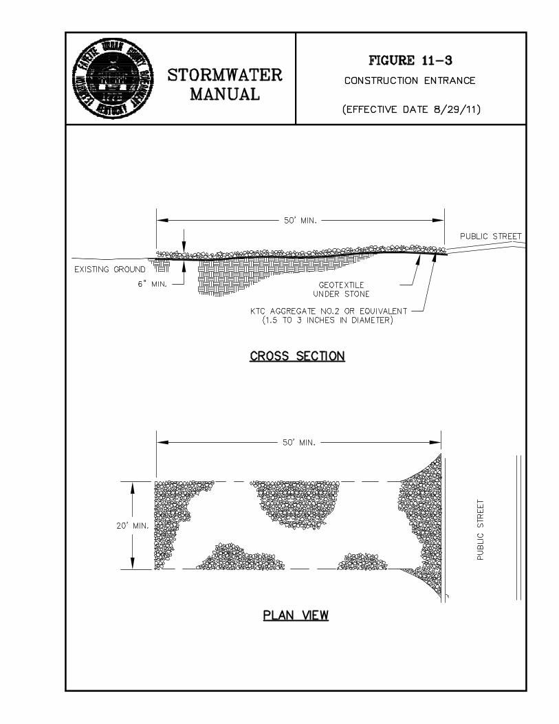
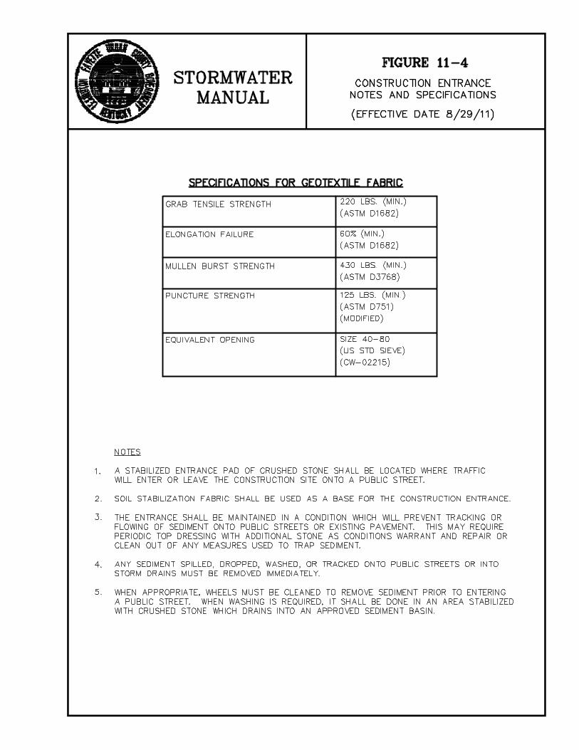
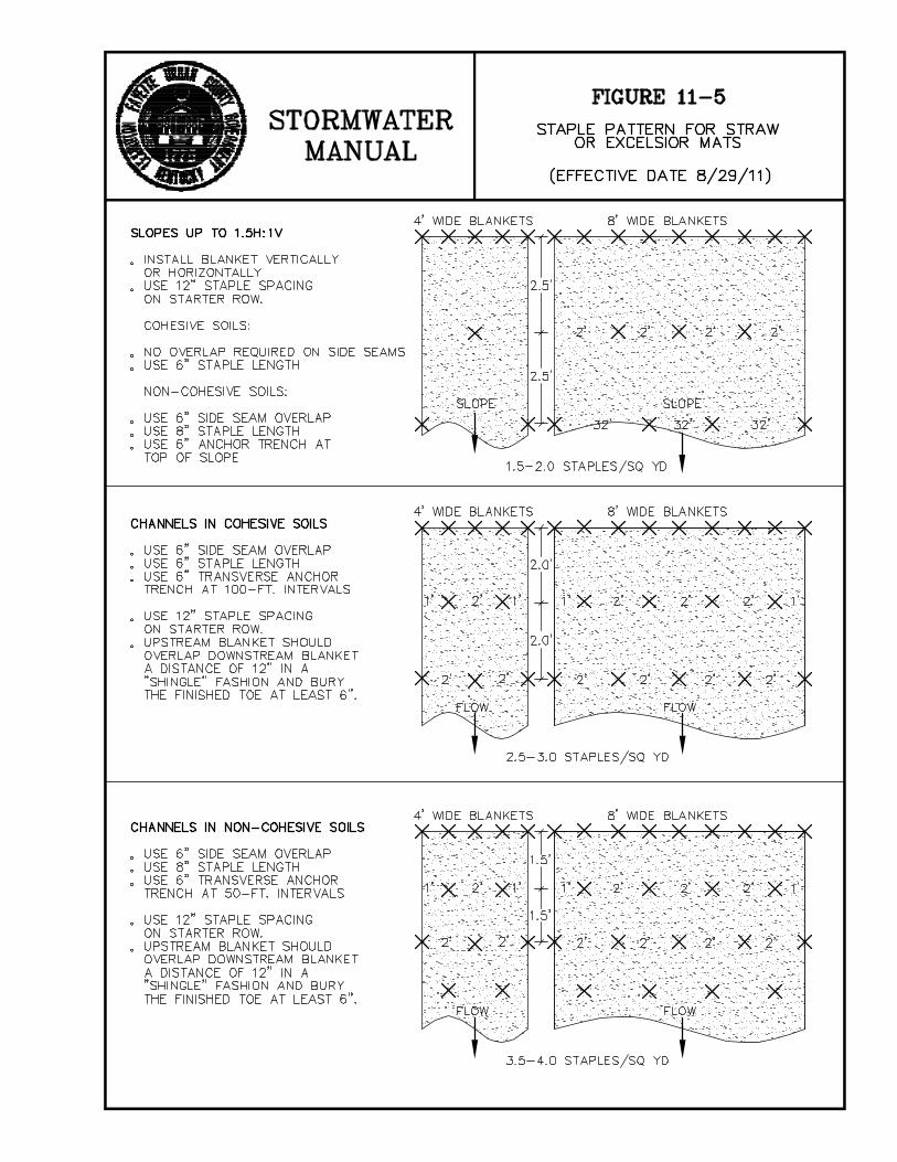

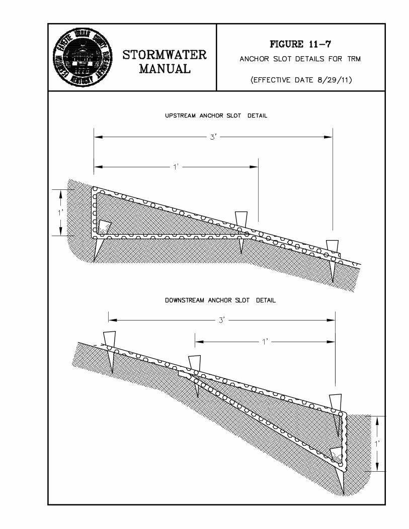
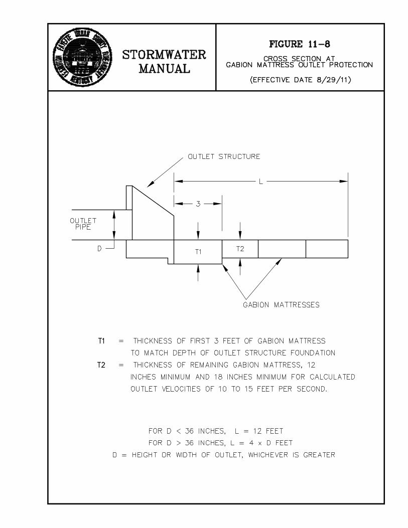
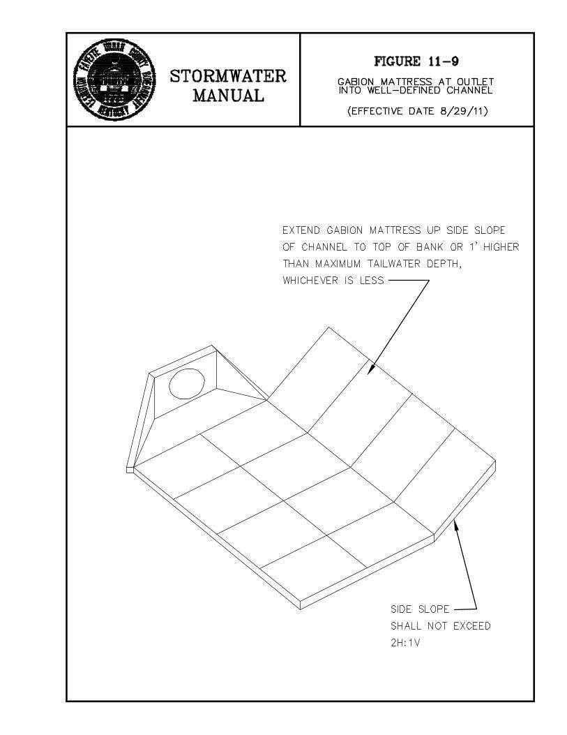


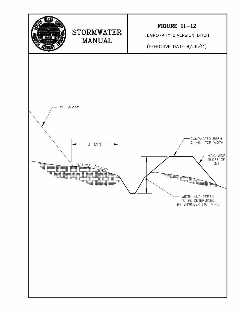
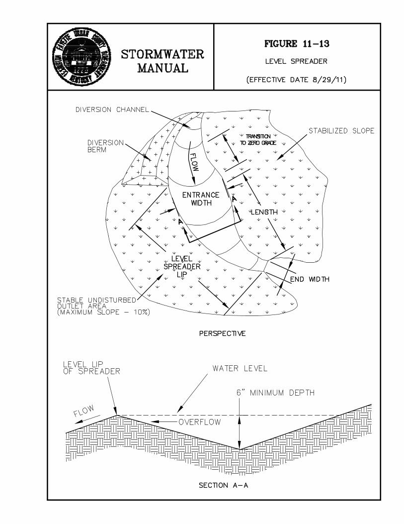
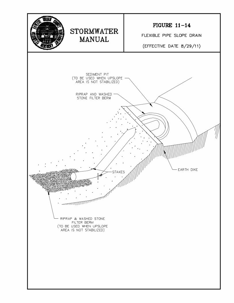


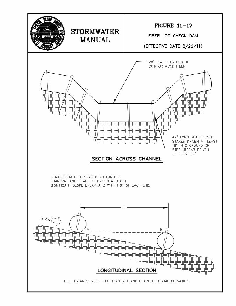
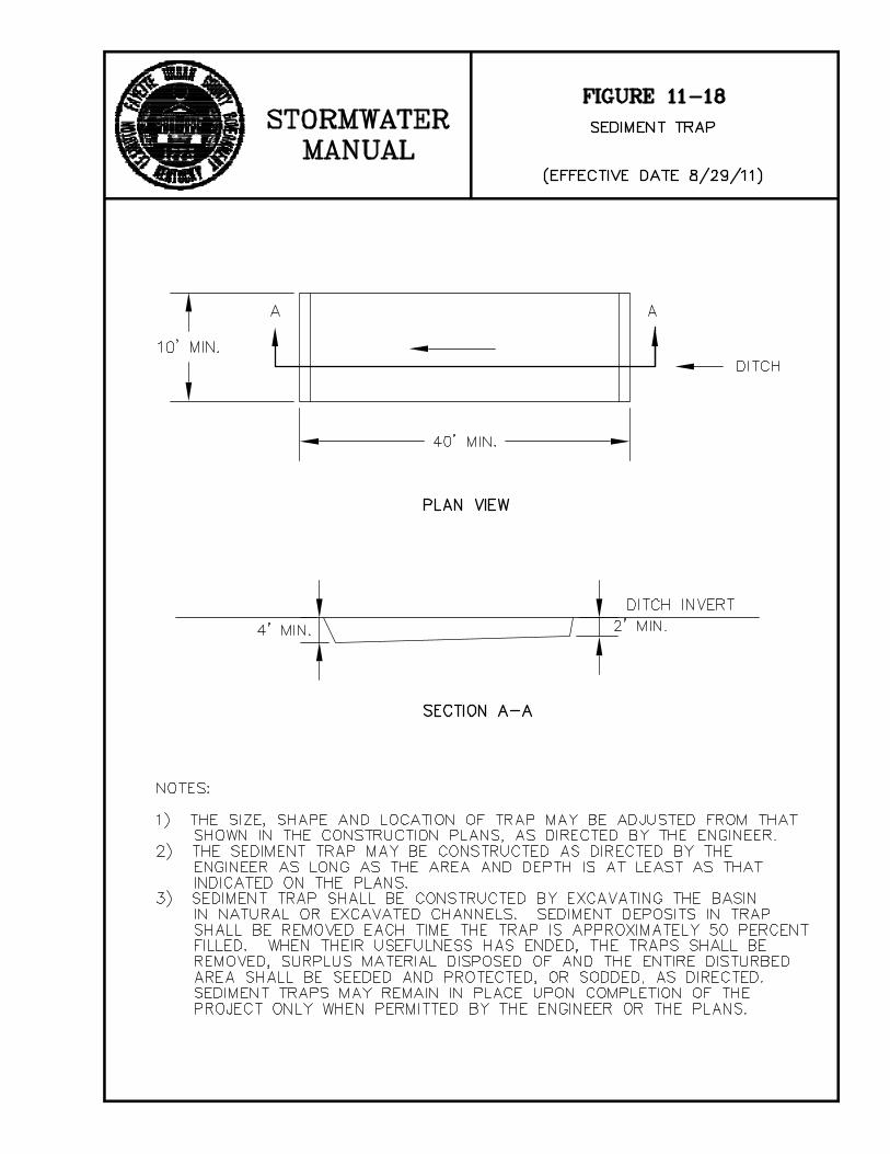
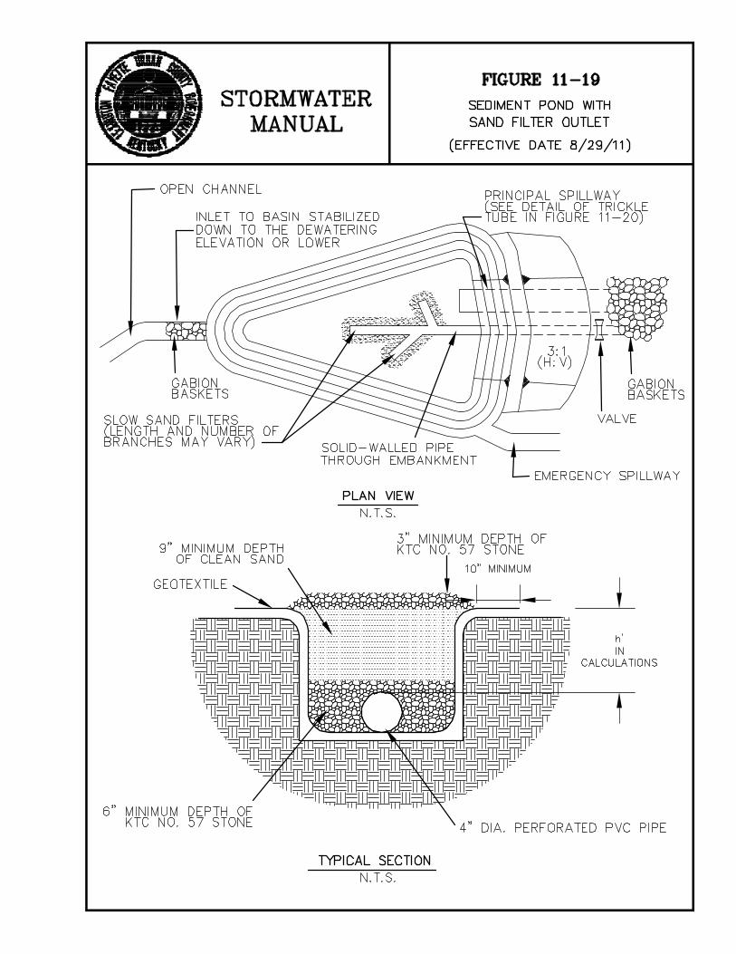


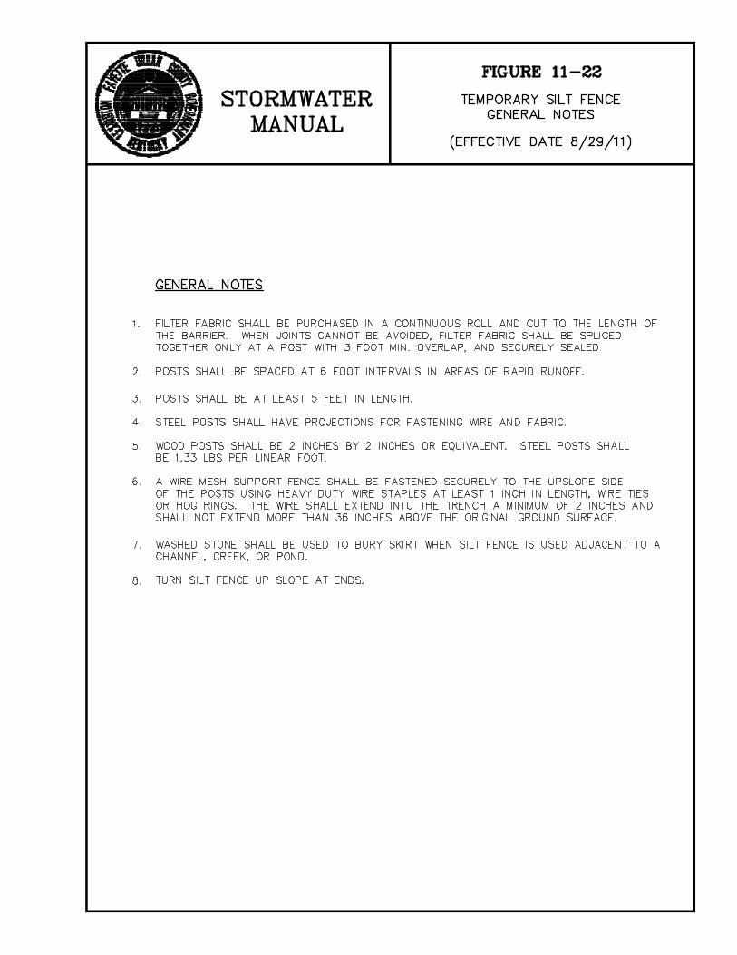

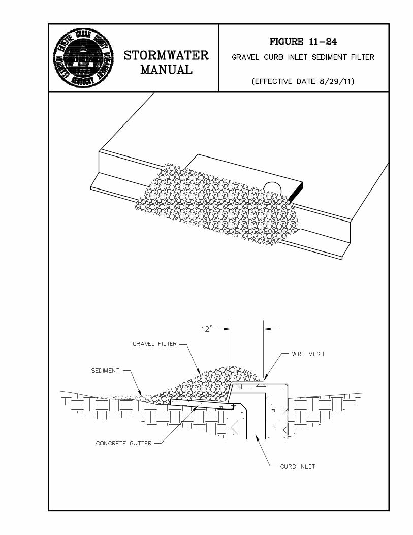


Page 1 of 3
Summary of Changes to the LFUCG Stormwater Manual
August 29, 2011
The changes below have been made to Chapter 2 and 11 of the LFUCG Stormwater Manual to ensure consistency with the new LFUCG ordinance entitled “Reduction of Soil Erosion” in Chapter 16, Article X, Division 5 of the Code of Ordinances; Kentucky’s KYR10 permit for construction activities; and the KY BMP Manual.
2.1 – References to “Grading Permit” were changed to “Land Disturbance Permit”.
11.1.1 Regulatory Basis - Revised the narrative to reference the Code of Ordinances.
11.2.1 Permitting Process – This section was added and the old text was deleted.
11.3 Erosion and Sediment Control Plans – Revised narrative to indicate when an erosion and sediment control plan is needed.
11.3.1 Written Description – Revised to be consistent with the ordinance.
11.3.2 Site Map – Revised to be consistent with the ordinance.
11.4.1 Mulch – material specifications for wood chips revised to conform to the KY BMP Manual.
11.4.3 Permanent Seed – The criteria for requiring reseeding was changed from 85% of groundcover to 70% of groundcover to conform to KYR10.
11.4.4 Sod – Sod application criteria and material specifications revised to conform to the KY BMP Manual.
11.4.10 Temporary Diversion Ditch – Design storm changed from 10 year-6 hour to 10 year-24 hour to conform to the KY BMP Manual. Construction specifications modified to conform to the KY BMP Manual.
11.4.12 Pipe Slope Drains – Design criteria changed to specify pipe size for given drainage area to conform to the KY BMP Manual. The basis for requiring maintenance of sediment

Page 2 of 3
traps was changed from 1/2 of the design volume to 1/3 of the design volume to conform to the KY BMP Manual.
11.5.1 Check Dams – The criteria for requiring maintenance, based on the depth of sediment, was changed from 1/2 of the original height of the dam to 1/3 of the original height to conform to the KY BMP Manual.
11.5.2 Sediment Traps - General design criteria was updated for design storms. The minimum capacity of the sediment trap to the elevation of the crest of the spillway was changed from 3600 cubic feet to the runoff volume from the 2-year, 24-hour storm to conform to KYR10. The maintenance level to require sediment removal was changed from 1/2 of the design volume to 1/3 third of design volume.
11.5.3 Sediment Ponds
• Maximum drainage area was revised from 100 acres to 120 acres to conform to the KY BMP Manual
• Design criteria clarified to require 80 percent removal of total suspended solids for the 10-year, 24-hour storm, or a detention time of 24-48 hours for the 10-year, 24-hour storm, to conform to the KY BMP Manual
• Minimum capacity of the sediment pond to the elevation of the crest of the pipe spillway was changed from 3600 cubic feet to the runoff volume from the 2-year, 24-hour storm to conform to KYR10
• Minimum top width of embankment changed from 10’ to 12’ to conform to the KY BMP Manual
• Minimum size of the pipe spillway was changed to 12” to conform to the KY BMP Manual.
• Basis for requiring maintenance for sediment removal was changed from 1/2 of the design volume to 1/3 of the design volume to conform to KYR10
11.5.4 Silt Fence – Material specifications for ‘Filtering Efficiency’ changed from 75% to 80% to conform to KYR10. Maintenance of silt fence changed to require removal of sediment when deposits reach 1/3 (versus 1/2) of the barrier height to conform to KYR10.

Page 3 of 3
11.5.5 Storm Drain Inlet Protection – Maintenance requirements changed to require maintenance at 1/3 (versus 1/2) of the design depth of the filter to conform to KYR10.