STORAGE BUILDING E512 - Kroftman
16
GSPublisherVersion 75.0.30.100 STORAGE BUILDING E512 14-7-2016 Kroftman Structures B.V. P.O. Box 158 6900AD Zevenaar The Netherlands T +31 26 700 9 700 F +31 84 8672 412 E [email protected] I www.kroftman.nl
Transcript of STORAGE BUILDING E512 - Kroftman

GSPublisherVersion 75.0.30.100
STORAGE BUILDING E512
14 -7 -2016
Kro f tman S t ruc tu res B .V .
P .O . Box 1586900AD ZevenaarThe Nether lands
T + 31 26 700 9 700F + 31 84 8672 412
E sales@ kro f tman.nlI www.kro f tman.nl

GSPublisherVersion 75.0.30.100
DESCRIPTION:
Date:
Drawn by:
Drawing scale:
01 (E512-EN)
A3
Building overview
J. van Dijk
1:100, 1:50
SHEET:
14-7-2016
Format:
TYPE: E512
All dimensions are in milimeters
Kro f tman S t ruc tu res B .V .
P .O . Box 158
6900AD Zevenaar
The Nether lands
T + 31 26 700 9 700
F + 31 84 8672 412
E sales@ kro f tman.nl
I www.kro f tman.nl
1 32
-50
±0
+2.765
+3.370
2.77
5
2.900
38860
38860
38860
3812551
1.050
1.900
metal side panel
metal roof panel
concrete slab
side post
dimensions of roof sheet metal
dimensions of purlins
04
02
01
03
GENERAL NOTES:1. MAXIMUM ALLOWABLE SOIL BEARING PRESSURE IS PER LOCAL CODE.2. MAXIMUM SIZE AGGREGATE SHALL BE AS FOLLOWS: 25.40mm DIA.3. MINIMUM COMPRESSIVE STRENGTH OF CONCRETE AT 28 DAYSPER LOCAL CODE.4. PLACE REINFORCEMENTS AT MID THICKNESS FOR SLABS ON THE GROUND.5. ALL SPLICES IN CONTINUOUS REINFORCEMENT OR REINFORCING AS USEDIN WALLS, FOOTINGS ,ETC. SHALL HAVE A MINIUM LAP OF 40 DIAMETERS.SPLICES IN ADJACENT BARS SHALL NOT BE LESS THAN 1.22m APART.
SCREW PATTERNS:SHEET METAL SCREWS:
SELF DRILLING SCREW HEXAGONALDIN 7504-K STEEL / GALVANIZED +PAINTED / NYLON WASHER4,8 MM TREAD, 25 MM LONG,USE MAGNETIC POWERBIT SIZE 8.
SEE PAGE E509-14-EN
DESIGN CRITERIA:STRUCTURE SIZE: 5.60 X 9.10 X 3.30 M FRAME.
THE STRUCTURE IS BASED ON:- NEN6702, NEN6770, NEN6771, NEN6772- EUROCODE 0, EUROCODE 1, EUROCODE 3- DIN1055-1, DIN1055-4, DIN1055-5
MATERIALS: SEE SEPARATE PARTS LIST
1 2 3
±0
+2.772
+3.370
5.645
garage door man door
metalside panel
note: dimensions including sheet metal
05
07
10 08 09
I H G F E D C B A
12.157
3 2 1
2.775 2.775
A B C D E F G H I
12.158
metal side panel
metal roof panel
transparantroof panel
butyl caulking strip(BC)
butyl caulking strip(BC)
butyl caulking strip(BC)
02
04
01
12.1
58
10 08garage door man door
09
11
A
B
D
C
E
G
F
I
H
1 32
A A
side post 50x50x4 mm
back vertical 50x50x3 mm
corner post 50x50x4 mm
A
B
D
C
E
G
F
I
H
1 32
A A
Section A-A
Front elevation Left side elevationBack elevationRight side elevation
Floor plan Top view

GSPublisherVersion 75.0.30.100
DESCRIPTION:
Date:
Drawn by:
Drawing scale:
02 (E512-EN)
A3
Frame overview
1:100
SHEET:
Format:
TYPE: E512
Kro f tman S t ruc tu res B .V .
P .O . Box 158
6900AD Zevenaar
The Nether lands
T + 31 26 700 9 700
F + 31 84 8672 412
E sales@ kro f tman.nl
I www.kro f tman.nl
50 1.458 50 1.458 50 1.458 50 1.458 50 1.458 50 1.458 50 1.458 50 1.508
12.114
50 1.325 50 2.75050
82501061
50 8250
50 1.800 50 1.800 50 1.800 50
501.
458
501.
458
501.
458
501.
458
501.
458
501.
458
501.
458
501.
458
50
5.600
12.1
14
5.600
13.2
13
A A
side post 50x50x4 mm
back vertical 50x50x3 mm
corner post 50x50x4 mm
38 86038 860
38 86038 125
2.70
3
4.026
5.700
5.700
3.29
8
rafter 50*50*3 mm
collar tie 25*25*2 mm
50 1.325 50 2.750 5082 50
106150 82
50
5.600
502.
600
648
502.126
399
note: dimensions frame only
50 1.800 50 1.800 50 1.800 50
5.600
50 1.458 50 1.458 50 1.458 50 1.458 50 1.458 50 1.458 50 1.458 50 1.458 50
12.114
985
1.02
51.
025
1.02
51.
025
1.02
51.
025
1.02
51.
025
1.02
51.
025
854
metal roof panel-40mmA
B
D
C
E
G
F
I
H
1 32
A A
rafter 50*50*3 mm
purlins 38*38*1,5 mm
transparant roofpanel
Right side elevation
Base rails
Section A-A
Front elevation Back elevation Left side elevation
Roof construction
14-7-2016 Version 1
J. van Dijk date14-08-2020
Alle maatvoering is in millimeters

GSPublisherVersion 75.0.30.100
DESCRIPTION:
Date:
Drawn by:
Drawing scale:
03 (E512-EN)
A3
3D frame
1:50
SHEET:
Format:
TYPE: E512
Kro f tman S t ruc tu res B .V .
P .O . Box 158
6900AD Zevenaar
The Nether lands
T + 31 26 700 9 700
F + 31 84 8672 412
E sales@ kro f tman.nl
I www.kro f tman.nl
B2D
A
G
F
H
E
C
B1
14-7-2016 Version 1
J. van Dijk date14-08-2020
Alle maatvoering is in millimeters

GSPublisherVersion 75.0.30.100
DESCRIPTION:
Date:
Drawn by:
Drawing scale:
04 (E512-EN)
A3
3D Construction details
1:2, 1:50
SHEET:
Format:
TYPE: E512
Kro f tman S t ruc tu res B .V .
P .O . Box 158
6900AD Zevenaar
The Nether lands
T + 31 26 700 9 700
F + 31 84 8672 412
E sales@ kro f tman.nl
I www.kro f tman.nl
no bracket
B4
steel 25x50x3 mm6 x screw B (SC-B)
B1
frame connections:4x bolt set 1 (BO-1)(M12 DIN 603 8.8 ZI)
1x bolt set 3 (BO-3)
frame connections:2x bolt set 6M8x40 (BO-6)
B2
purlin (roof cross profile)38x38x1,5 mm
side post (vertical profile)50x50x4 mm
4 x bolt set 1 (BO-1)
Pre-drill top: 16 mmbottom: 6 mm
- 2 x screw B (SC-B)
rafter (roof profile),50x50x3 mm
B5
BO-2, bolt set 2flat head bolt M12x75 DIN8.8 (50mm straight shaft) + washer + hex nut, all galvanized->End truss connections (top and eaves)
BO-1, bolt set 1hex bolt M12x80 DIN8.8 (60mm straight shaft) + washer + hex nut, all galvanized->Intermediate truss connections (top and eaves):
CONNECTIONS(for blue marked texts: see Kroftman E509 Parts List)
SC-B, screw B4,8 x 20 mm self tapping screw->Horizontal door beam connections->Roof purlin/truss connection->End wall vertical/truss connections inner side-> Vertical support to base rail. See detail 11.
BO-4, bolt set 4hex bolt M8x75 DIN8.8 + washer + hex nut->Collar tie/truss connection
SC-C, Screw Cpan head screw, 4,8 x25 mm->End wall vertical/truss connections out side
BO-3, bolt set 3hex bolt M8x75 DIN8.8 + washer + hex nut, + nylon spacers (outside Ø15.9, insideØ8.5 mm, length 10 mm) all galvanized->Collar tie vertical support/truss connection->Collar tie/truss connection
(BO-1)
(SC-B) = Screw B
= Bolt set 1
= Bracket 5
BO-5, bolt set 5hex bolt M8x35 DIN8.8 + washer + hex nut->Collar tie/collar tie connection
EAB, Expansion Anchor Boltancher bolts 12x180mm galvanized->Foundation anchors
BO-6, bolt set 6hex bolt M8x40 DIN8.8 + washer + hex nut->Vertical support to collar tie connection
SC-A, screw A4,8 x 25 mm self tapping screw, painted + rubber washer-> Steel sheeting
Detail B-2 (outside)
Detail B-1 (inner side)
Detail A
Detail C14-7-2016 Version 1
J. van Dijk date14-08-2020
Alle maatvoering is in millimeters

GSPublisherVersion 75.0.30.100
DESCRIPTION:
Date:
Drawn by:
Drawing scale:
05 (E512-EN)
A3
3D Construction details
1:2, 1:50
SHEET:
Format:
TYPE: E512
Kro f tman S t ruc tu res B .V .
P .O . Box 158
6900AD Zevenaar
The Nether lands
T + 31 26 700 9 700
F + 31 84 8672 412
E sales@ kro f tman.nl
I www.kro f tman.nl
end truss
4 x bolt set 2(BO-2)
B2
2 x bolt set 5(BO-5)
25x25x2 mm
Foundation anchor(EAB)
3 x (screw B)inner side
3 x
B3
25x25x2 mm
bolt set 3,(BO-3)
2 x bolt set 4(BO-4)
B5
40x40x3 mm6x screw B (SC-B)
B5
BO-2, bolt set 2flat head bolt M12x75 DIN8.8 (50mm straight shaft) + washer + hex nut, all galvanized->End truss connections (top and eaves)
BO-1, bolt set 1hex bolt M12x80 DIN8.8 (60mm straight shaft) + washer + hex nut, all galvanized->Intermediate truss connections (top and eaves):
CONNECTIONS(for blue marked texts: see Kroftman E509 Parts List)
SC-B, screw B4,8 x 20 mm self tapping screw->Horizontal door beam connections->Roof purlin/truss connection->End wall vertical/truss connections inner side-> Vertical support to base rail. See detail 11.
BO-4, bolt set 4hex bolt M8x75 DIN8.8 + washer + hex nut->Collar tie/truss connection
SC-C, Screw Cpan head screw, 4,8 x25 mm->End wall vertical/truss connections out side
BO-3, bolt set 3hex bolt M8x75 DIN8.8 + washer + hex nut, + nylon spacers (outside Ø15.9, insideØ8.5 mm, length 10 mm) all galvanized->Collar tie vertical support/truss connection->Collar tie/truss connection
(BO-1)
(SC-B) = Screw B
= Bolt set 1
= Bracket 5
BO-5, bolt set 5hex bolt M8x35 DIN8.8 + washer + hex nut->Collar tie/collar tie connection
EAB, Expansion Anchor Boltancher bolts 12x180mm galvanized->Foundation anchors
BO-6, bolt set 6hex bolt M8x40 DIN8.8 + washer + hex nut->Vertical support to collar tie connection
SC-A, screw A4,8 x 25 mm self tapping screw, painted + rubber washer-> Steel sheeting
Detail E
Detail H
Detail G
Detail FDetail D
14-7-2016 Version 1
J. van Dijk date14-08-2020
Alle maatvoering is in millimeters

GSPublisherVersion 75.0.30.100
DESCRIPTION:
Date:
Drawn by:
Drawing scale:
06 (E512-EN)
A3
Detail 01, 10, 11
1:2
SHEET:
Format:
TYPE: E512
Kro f tman S t ruc tu res B .V .
P .O . Box 158
6900AD Zevenaar
The Nether lands
T + 31 26 700 9 700
F + 31 84 8672 412
E sales@ kro f tman.nl
I www.kro f tman.nl
base rail
horizontal side metal
vertical profile
U-shaped profile
self drilling screw (SC-A)
3 x self drilling screw (SC-B)
end of the concrete slab
optional sheeting ledge
corner post 50x50x4 mm
closure strip (foam seal) (FS-2)
50
50
corner trim (T3)self drilling screw (SC-A)
horizontal side metal
50x50x3mmbase rail down
the length of the building
1
A
-100
±0
+50
125 50
50
150
150 150
300
300 300
600
anchor bolt (EAB)located 127 mm from each post
MKT B12-85-100/180ev
factory drilled 16 mm
concrete slab is optional
concrete slab/footings
(grade)
anchor hold down force 875 kgs. specialinspection is not required for occupancygroup: R-3 and U-1. ES report: ESR-2251
steel reinforcement : seeconstruction rapport
(width including concrete slab)
(width without concrete slab)
300
mm
min
. or t
o fro
st li
ne
base rail downthe length of building
50x50x3 MM STEEL, S355J2
flat washer
horizontal side metal
self drilling screw (SC-A)
butyl caulking strip (BC)
1
11 (top view)
10 (top view)
01 (front view)
275/125
275/125
14-7-2016 Version 1
J. van Dijk date14-08-2020
Alle maatvoering is in millimeters

GSPublisherVersion 75.0.30.100
DESCRIPTION:
Date:
Drawn by:
Drawing scale:
07 (E512-EN)
A3
Detail 02, 03
1:2
SHEET:
Format:
TYPE: E512
Kro f tman S t ruc tu res B .V .
P .O . Box 158
6900AD Zevenaar
The Nether lands
T + 31 26 700 9 700
F + 31 84 8672 412
E sales@ kro f tman.nl
I www.kro f tman.nl
at front and backfasten eave trim withpan head screw (SC-C)
eave trim (T2)
Roof panel
Transparant roof paneel
roof frame 50*50*3
self drilling screw (SC-A)
purlin 38x38x1.5mm
butyl caulking strip (BC)
+2.703
16
28
51
horizontal side metal0.5mm steel, 80 KSI
eave trim (T2)
roof metal,50.8 mm overhang
closure strip (foam seal)(FS-1B)
purlin 38x38x1,5 mm
side post50x50x4 mm
steel, S355J2
16 mm pre-drilled
self drilling hex screw6 mm factory drilled
fram
e 50
*50*
4
steel 6 mm
1
self drilling screw(SC-A)
self drilling screw(SC-A)
16
collar tie 25x25x2steel
bracket, steel 4mm, (B3)
roof metal0.5mm steel, 80 KSI
bolt set 3 (BO-3)
16 mm factory drilled
self drilling screw (SC-A)
purlin 38x38x1.5mm
bolt set 4 (BO-4)
roof frame 50*50*3
frame 25*25*2
02a
03a (front view)02 (front view)
03 (front view)
self drilling screw (SC-B)
14-7-2016 Version 1
J. van Dijk date14-08-2020
Alle maatvoering is in millimeters
GSPublisherVersion 75.0.30.100
DESCRIPTION:
Date:
Drawn by:
Drawing scale:
08 (E512-EN)
A3
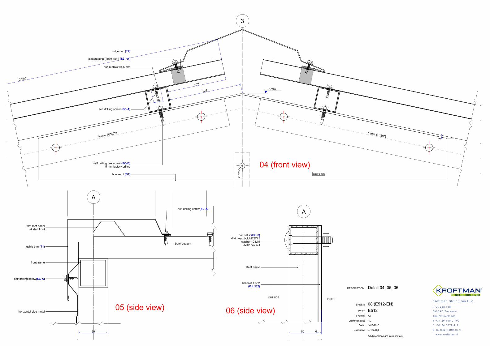
Detail 04, 05, 06
J. van Dijk
1:2
SHEET:
14-7-2016
Format:
TYPE: E512
All dimensions are in milimeters
Kro f tman S t ruc tu res B .V .
P .O . Box 158
6900AD Zevenaar
The Nether lands
T + 31 26 700 9 700
F + 31 84 8672 412
E sales@ kro f tman.nl
I www.kro f tman.nl
3
+3.299
16
125
2.900
102
closure strip (foam seal) (FS-1A)
ridge cap (T4)
self drilling hex screw (SC-B)5 mm factory drilled
self drilling screw (SC-A)
bracket 1 (B1)
frame 50*50*3
25*2
5*2
steel 6 mm
3
frame 50*50*3
purlin 38x38x1.5 mm
butyl sealant
self drilling screw(SC-A)
self drilling screw(SC-A)
50
horizontal side metal
gable trim (T1)
front frame
first roof panelat start front
A
bracket 1 or 2(B1 / B2)
steel frame
bolt set 2 (BO-2)-flat head bolt M12X75
-washer 12 MM-M12 hex nut
OUTSIDE INSIDE
50 6
A
04 (front view)
05 (side view) 06 (side view)

GSPublisherVersion 75.0.30.100
DESCRIPTION:
Date:
Drawn by:
Drawing scale:
09 (E512-EN)
A3
Detail 07, 08, 09, 17A
1:2, 1:5
SHEET:
Format:
TYPE: E512
Kro f tman S t ruc tu res B .V .
P .O . Box 158
6900AD Zevenaar
The Nether lands
T + 31 26 700 9 700
F + 31 84 8672 412
E sales@ kro f tman.nl
I www.kro f tman.nl
5050
150
+2.650
+2.700
250
25 25
50
door opening frame
j-trim (T5)
angle trim(T6)
garage door
horizontal side metal
self drilling screw (SC-A)
tube 50x50x3(17A)
A
garage doorcentered in opening
door opening frame(jamb)
horizontal side metal
angle trim(T-6)
self drilling hex screw (SC-A)
j-trim (T-5)
tube 50x50x3 Length 250 mm(17A)
A
self drilling hex screw (SC-A)
j-trim (T-5)
07 (side view)
08 (top view)
09 (top view)
50 50
250
5050
150
tube 50x50x3,h=250 mm
part 17A inner sidegarage door
bracketgarage door
17A front view
14-7-2016 Version 1
J. van Dijk date14-08-2020
Alle maatvoering is in millimeters

GSPublisherVersion 75.0.30.100
DESCRIPTION:
Date:
Drawn by:
Drawing scale:
10 (E512-EN)
A3
Frame parts
1:50
SHEET:
Format:
TYPE: E512
Kro f tman S t ruc tu res B .V .
P .O . Box 158
6900AD Zevenaar
The Nether lands
T + 31 26 700 9 700
F + 31 84 8672 412
E sales@ kro f tman.nl
I www.kro f tman.nl
151
2.50
0
2.830 2.830
390
2.913 1.113
151
2.50
0
14 15
16
12 12
13 13
151
2.50
0
150 1.275 2.750 182 1061 132
2.750
250 50
2.830 2.830
2.75
4
965
2.53
8
21
3 4
12
13
17 17 22 23
18 20
13
1 2a 2b
12
17A 17A
151
2.50
0
2.830 2.830
151
2.50
0
150 2.650 2.650 150
150 1.700 50 900 900 50 1.700 150
5010
12.
894
2.89
4
89
19 19
11 10
12
1313
12
3.015 1 3.015 1 3.016 1 3.016
50 865 593 50 1.458 50 726 732 50 1.458 50 726 732 50 1.458 50 726 732 50 1.458 50
915 2.877 3.016 3.016 2.290
U-shaped beamat part 7
U-shaped beamat part 6
U-shaped beamat part 7
U-shaped beamat part 9
21 21 21
12 12 12 12 12 12 12
4 6 7R
12 12
7R 9
21
3.016 1 3.016 1 3.015 1 3.015
50 1.458 50 732 726 50 1.458 50 732 726 50 1.458 50 732 726 50 1.458 50 593 865 50
2.290 3.016 3.016 2.877 915
U-shaped beamat part 7
U-shaped beamat part 8
U-shaped beamat part 5
U-shaped beamat part 77L7L8
21 21 21
12 12 12 12 12 12 12 1212
35
21
intermediate truss
front wall
back wall
right wall
left wall
14-7-2016 Version 1
J. van Dijk date14-08-2020
Alle maatvoering is in millimeters

GSPublisherVersion 75.0.30.100
DESCRIPTION:
Date:
Drawn by:
Drawing scale:
11 (E512-EN)
A3
Elevations panel numbering andscrew patterns
1:50, 1:10
SHEET:
Format:
TYPE: E512
Kro f tman S t ruc tu res B .V .
P .O . Box 158
6900AD Zevenaar
The Nether lands
T + 31 26 700 9 700
F + 31 84 8672 412
E sales@ kro f tman.nl
I www.kro f tman.nl
1 2 3
±0
+2.772
+3.370
5.645
1.430
2.900
1.430
garage door man door
metalside panel
note: dimensions including sheet metal
S7
S7
S7
S7
S7 S7
S7S6
S7
S7 S7
05
07
10 08 09
A B C D E F G H I
12.158
2900
1.090
3.080
900
900
900
3.080
3.080
3.080
1.090
829
1.050
metal side panel
metal roof panel
transparantroof panel
butyl caulking strip(BC)
butyl caulking strip(BC)
butyl caulking strip(BC)
S4
S4
S4
S4 S4
S4 S4
S4 S4
S2 S2S1 S1 S1 S3 S1 S1 S3 S1 S1
S4
S4
S4
S2S3 S1 S1
02
04
01
screw pattern wall panelscrew pattern roof panel
Front elevation Right side elevation
2 screws each rib
2 screws each rib
1 screw each rib
1 screw each rib
1 screw above each rib
upper screw below rib
14-7-2016 Version 1
J. van Dijk date14-08-2020
Alle maatvoering is in millimeters

GSPublisherVersion 75.0.30.100
DESCRIPTION:
Date:
Drawn by:
Drawing scale:
12 (E512-EN)
A3
Elevations panel numbering andscrew patterns
1:50, 1:10
SHEET:
Format:
TYPE: E512
Kro f tman S t ruc tu res B .V .
P .O . Box 158
6900AD Zevenaar
The Nether lands
T + 31 26 700 9 700
F + 31 84 8672 412
E sales@ kro f tman.nl
I www.kro f tman.nl
3 2 1
2.775 2.775
1.950 1.950
1.950
S5 S5 S5
S5 S5S5
S5 S5S5
S5 S5S5
I H G F E D C B A
12.157
3.080
3.080
3.080
3.080
S4
S4
S4
S4 S4
S4 S4
S4 S4
S4
S4
S4
screw pattern wall panelscrew pattern roof panel
Back elevation Left side elevation
2 screws each rib
2 screws each rib
1 screw each rib
1 screw each rib
1 screw above each rib
upper screw below rib
14-7-2016 Version 1
J. van Dijk date14-08-2020
Alle maatvoering is in millimeters

GSPublisherVersion 75.0.30.100
DESCRIPTION:
Date:
Drawn by:
Drawing scale:
13 (E512-EN)
A3
Anchor plan type 1 (OPTIONGROUND ANCHOR)
1:5, 1:50
SHEET:
Format:
TYPE: E512
Kro f tman S t ruc tu res B .V .
P .O . Box 158
6900AD Zevenaar
The Nether lands
T + 31 26 700 9 700
F + 31 84 8672 412
E sales@ kro f tman.nl
I www.kro f tman.nl
13
2
12.114
5.600
25152
1.0713.020
441.173
9025
25 12.064 25
12.114
177 1.204 304 1.204 304 1.204 304 1.204 304 1.204 304 1.204 304 1.204 304 1.204 152 25
5.600
255.550
25
25152
1.5461.077
7731.850
15225
A B D EC GF IH
A
A
AAAAA
AA
AA
AA
A
A A AAAA
A
AA
AA
AA
AA
AA
A
AA
AA
AA
AA
50±0
L =
1100
mm
dept
h an
chor
ground anchor Ø 25 mm (GA)pre-drilling in base profile Ø 30 mm
GRADE
BASE RAIL DOWNTHE LENGTH OF BUILDING50x50x3 MM STEEL, S355J2
01a
FRON
T SIDE
REAR SID
E
40 ANCHORS
DEPTH ANCHOR: 1200 MMLENGTH GROUND ANCHOR: 1200 + 100 MM = 1300 MM
14-7-2016 Version 1
J. van Dijk date14-08-2020
Alle maatvoering is in millimeters

GSPublisherVersion 75.0.30.100
DESCRIPTION:
Date:
Drawn by:
Drawing scale:
14 (E512-EN)
A3
Foundation without slab, anchorplan type 2
1:50, 1:10
SHEET:
Format:
TYPE: E512
Kro f tman S t ruc tu res B .V .
P .O . Box 158
6900AD Zevenaar
The Nether lands
T + 31 26 700 9 700
F + 31 84 8672 412
E sales@ kro f tman.nl
I www.kro f tman.nlINSTRUCTION FOUNDATION: SEE STATIC CALCULATION INGENIEURBURÖ FRANK BLASEK (BÜREN), PROJECTNR. 1033N-13EC
13
2
12.114
5.600
25152
1.0713.020
441.173
9025
25 12.064 25
25 12.064 25
25 152 1.204 152 152 1.204 152 152 1.204 152 152 1.204 152 152 1.204 152 152 1.204 152 152 1.204 152 152 1.204 152 25
5.600
252.775
2.77525
25152
1.5461.077
7731.850
15225
6.150
600 11.464 600
12.664
6004.950
600
D
D
DDDDD
DD
DD
DD
D
D D DDDD
D
DD
DD
DD
DD
DD
D
DD
DD
DD
DD
A B D EC GF IH
50
300 300
600
800
800
600 11.464 600
12.664
01b
800
6004.950
600
6.150
01b
Section length
Section
FRON
T SIDE
REAR SID
E
40
anchor type Fischer FAZ II 12/50, L= 180mm
Anchors
14-7-2016 Version 1
J. van Dijk date14-08-2020
Alle maatvoering is in millimeters
GSPublisherVersion 75.0.30.100
DESCRIPTION:
Date:
Drawn by:
Drawing scale:
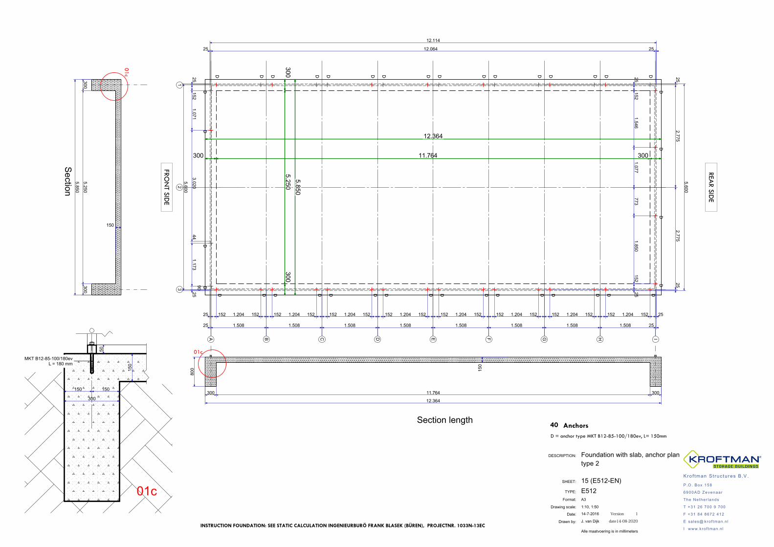
15 (E512-EN)
A3
Foundation with slab, anchor plantype 2
1:10, 1:50
SHEET:
Format:
TYPE: E512
Kro f tman S t ruc tu res B .V .
P .O . Box 158
6900AD Zevenaar
The Nether lands
T + 31 26 700 9 700
F + 31 84 8672 412
E sales@ kro f tman.nl
I www.kro f tman.nlINSTRUCTION FOUNDATION: SEE STATIC CALCULATION INGENIEURBURÖ FRANK BLASEK (BÜREN), PROJECTNR. 1033N-13EC
50
150
150 150
300
MKT B12-85-100/180evL = 180 mm
13
2
12.114
5.600
25152
1.0713.020
441.173
9025
25 12.064 25
25 1.508 1.508 1.508 1.508 1.508 1.508 1.508 1.508 25
25 152 1.204 152 152 1.204 152 152 1.204 152 152 1.204 152 152 1.204 152 152 1.204 152 152 1.204 152 152 1.204 152 25
5.600
252.775
2.77525
25152
1.5461.077
7731.850
15225
300 11.764 300
12.364
5.850300
5.250300
D
D
DDDDD
DD
DD
DD
D
D D DDDD
D
DD
DD
DD
DD
DD
D
DD
DD
DD
DD
A B D EC GF IH
300 11.764 300
12.364
150
01c
3005.250
300
5.850
150
01c
01c
Section length
Section
FRON
T SIDE
REAR SID
E
40D = anchor type MKT B12-85-100/180ev, L= 150mm
Anchors
800
14-7-2016 Version 1
J. van Dijk date14-08-2020
Alle maatvoering is in millimeters