Stoneridge Electronics Digital Tachograph SE5000 User · PDF fileStoneridge Electronics...
63
UK USER MANUAL Page 1 9000-101534_01R01 USER_MANUAL_ENGLISH Copyright © 2005 Stoneridge Electronics AB Part Number 6800-900 Manufacturers of VEEDER-ROOT Tachographs Stoneridge Electronics Digital Tachograph SE5000 User Manual
Transcript of Stoneridge Electronics Digital Tachograph SE5000 User · PDF fileStoneridge Electronics...
UK
USER MANUAL Page 1 9000-101534_01R01 USER_MANUAL_ENGLISH Copyright © 2005 Stoneridge Electronics AB Part Number 6800-900 Manufacturers of VEEDER-ROOT Tachographs
Stoneridge Electronics
Digital Tachograph SE5000
User Manual

UK
USER MANUAL Page 2 9000-101534_01R01 USER_MANUAL_ENGLISH Copyright © 2005 Stoneridge Electronics AB Part Number 6800-900 Manufacturers of VEEDER-ROOT Tachographs
I M P O R T A N T I N F O R M A T I O N
Due to driver and road safety requirements, it is strongly advised that driver interaction with a Digital Tachograph Vehicle Unit (VU) is not carried out whilst a vehicle is in motion (Note: the term ‘VU’ will be used to describe a Digital Tachograph from this point forward). If a driver does not have a valid VU driver smartcard they must not drive a vehicle fitted with the VU described in this manual as it is against EU law. If a card is lost, stolen or faulty, a temporary exemption to drive without a card may be granted by the national enforcement agency of the country in which driving is to be done. Drivers should contact national enforcement agencies directly (as indicated in Appendix 7 - National Enforcement Agencies) for clarification on this matter - drivers are responsible for ensuring that they obey driving laws. Driver smartcards contain a memory storage area that is used to hold driver activity data. Typically 28 days of driver activity can be stored on a driver smartcard. It should be noted that once the data memory storage area on a driver smartcard becomes full then any new driver activity data will still be stored but the oldest data on the smartcard will be overwritten and permanently lost. A description of the types of driver activity data stored are given in Appendix 3 - Driver Card Insertion and Withdrawal and Driver Activity Data. Driver card owners must take care of their personal driving card. Driver cards are not transferable and shall not be made available to any other person. Smartcards must be handled with care – do not flex or bend the cards. Ensure that the card contacts are kept free from dirt – clean with a soft damp cloth if necessary. Dirt ingress can lead to premature failure of a VU. Ensure that Smartcard drawers are closed at all times, except when inserting or removing cards. Also ensure that the paper cassette is closed at all times except when changing the printer paper. When accessing the printer paper do not use excessive force when removing the paper cassette from its compartment. It should also be noted that the printer paper fitted must be a Stoneridge approved type and it must be stored in a cool, dark and dry environment. The VU smartcard drawers are not capable of supporting weight in the open position. Disconnect the electrical supply to the VU if:
• Electrical welding is carried out on the vehicle. • Prolonged boost starting is anticipated.
UK
USER MANUAL Page 3 9000-101534_01R01 USER_MANUAL_ENGLISH Copyright © 2005 Stoneridge Electronics AB Part Number 6800-900 Manufacturers of VEEDER-ROOT Tachographs
High-level transient voltage can cause permanent damage to VU electronic circuits. Similarly, failure of other electrical components on the vehicle, for example the alternator regulator, may result in damage to the VU, which is permanently connected to the battery. Any permanent damage done to a VU in this way will result in the VU warranty being invalidated. The EMC performance of the Stoneridge VU complies with the requirements of EU Commission Directive 95/54/EC. A VU case must never be opened, tampered with or manipulated, even in a Tachograph Workshop – if it is then it will become invalid for use. In the case of any exterior damage to a VU, it is recommended that the VU be presented to a Tachograph Workshop for evaluation. If a VU does not pass an evaluation it will be decommissioned and will require replacing. The Stoneridge VU has a normal operating temperature range of –25°C to +70°C. (Note: ADR version range is –25°C to +65°C). If the VU UTC time is inaccurate by a magnitude of greater than ±20 minutes, then the system must be returned to a Tachograph Workshop for recalibration.
UK
USER MANUAL Page 4 9000-101534_01R01 USER_MANUAL_ENGLISH Copyright © 2005 Stoneridge Electronics AB Part Number 6800-900 Manufacturers of VEEDER-ROOT Tachographs
CONTENTS
I M P O R T A N T I N F O R M A T I O N ...........................................................................................................2 CONTENTS ............................................................................................................................................................4 LIST OF FIGURES .................................................................................................................................................6 1 Introduction ........................................................................................................................................................7 2 Description of the Digital Tachograph System...............................................................................................8 3 Description of the Controls...............................................................................................................................9
3.1 Driver Duty-Change / Smartcard Eject Buttons......................................................................................................10 3.1.1 Duty Change Function.................................................................................................................................................................10 3.1.2 Smartcard Eject Function............................................................................................................................................................10
3.2 Enter Button ..............................................................................................................................................................10 3.3 Cancel Button............................................................................................................................................................11 3.4 Up / Down Buttons....................................................................................................................................................11 3.5 Smartcard Drawers ...................................................................................................................................................11 3.6 Paper Cassette ..........................................................................................................................................................11
3.6.1 Printer Paper Insertion ................................................................................................................................................................12 3.7 Display .......................................................................................................................................................................13
4 Driving...............................................................................................................................................................14 4.1 Inserting a Card.........................................................................................................................................................15 4.2 Manual Entries for Duties and Locations................................................................................................................17
4.2.1 Manual Entry of Duties – Continuation of Current Daily Work Period....................................................................................18 4.2.1.1 Manual Entry of Duties – Modification of Entries ..................................................................................................................19 4.2.2 Manual Entry of Duties – New Daily Work Period .....................................................................................................................20 4.2.2.1 Manual Entry of Duties – New Daily Start Time to Card Insertion Time Only ....................................................................20 4.2.2.2 Manual Entry of Duties – Last Card Withdrawal to Daily Work Period End & New Daily Start to Card Insertion...........21 4.2.3 Manual Entry of Locations ..........................................................................................................................................................22
4.3 Standard ‘Driving’ Display .......................................................................................................................................22 4.4 Duty Setting...............................................................................................................................................................23
UK
USER MANUAL Page 5 9000-101534_01R01 USER_MANUAL_ENGLISH Copyright © 2005 Stoneridge Electronics AB Part Number 6800-900 Manufacturers of VEEDER-ROOT Tachographs
4.5 Alternative Driving Displays ....................................................................................................................................24 4.5.1 Out of Scope Driving ...................................................................................................................................................................24 4.5.2 Ferry/Train Crossing Mode Selection ........................................................................................................................................25
4.6 Ejecting a Card..........................................................................................................................................................25 4.7 Driving Without a Valid Smartcard ..........................................................................................................................26 4.8 Dual-Driver Operation...............................................................................................................................................27
5 Printouts ...........................................................................................................................................................28 5.1 Types of Printout.......................................................................................................................................................28 5.2 How to Initiate a Printout and How to Stop a Printout ...........................................................................................29 5.3 Sample Printout.........................................................................................................................................................29
6 Settings Menu ..................................................................................................................................................31 6.1 UTC Time and Local Time ........................................................................................................................................31
6.1.1 Adjusting VU UTC Time...............................................................................................................................................................32 6.1.2 Setting VU Local Time .................................................................................................................................................................32
6.2 Inverting the Display.................................................................................................................................................32 6.3 Built-In Test ...............................................................................................................................................................33
7 VU Warnings (Events and Faults Conditions) ..............................................................................................34 7.1 General Events Warning Messages.........................................................................................................................34 7.2 VU Related Security Breach Attempt Events Warning Messages ........................................................................36 7.3 Sensor Related Security Breach Attempt Events Warning Messages .................................................................37 7.4 Recording Equipment Faults Warning Messages..................................................................................................37 7.5 Card Faults Warning Messages...............................................................................................................................38 7.6 Manufacturer Specific Events & Faults Warning Messages .................................................................................38
8 Care and Maintenance of a VU .......................................................................................................................42 8.1 Cleanliness ................................................................................................................................................................42 8.2 Protecting the VU System from Damage ................................................................................................................42 8.3 Printer Maintenance..................................................................................................................................................42
9 VU Periodic Inspections and Security Checks .............................................................................................43 10 Stoneridge ADR Digital Tachograph............................................................................................................43
UK
USER MANUAL Page 6 9000-101534_01R01 USER_MANUAL_ENGLISH Copyright © 2005 Stoneridge Electronics AB Part Number 6800-900 Manufacturers of VEEDER-ROOT Tachographs
Appendix 1 - VU Display Symbols ....................................................................................................................45 Appendix 2 - Tachograph Location Countries/Regions .................................................................................49 Appendix 3 - Driver Card Insertion and Withdrawal and Driver Activity Data..............................................50 Appendix 4 - Details of Printing Routines ........................................................................................................51 Appendix 5 - Display Screens Selectable Whilst Driving ...............................................................................56 Appendix 6 - Printer Spare Parts.......................................................................................................................57 Appendix 7 - National Enforcement Agencies.................................................................................................57 Appendix 8 - Troubleshooting (Built-In Tests).................................................................................................59 Appendix 9 - VU Driving Display and Main Menu Navigation ........................................................................60 Appendix 10 - Glossary of Terms......................................................................................................................62 LIST OF FIGURES Figure 1 Illustration of the Controls....................................................................................................................................9 Figure 2 Paper Cassette Removal...................................................................................................................................12 Figure 3 Printer Paper Orientation ...................................................................................................................................13 Figure 4 Flow Chart of Normal Driving Operation .........................................................................................................14 Figure 5 Flow Chart of Smartcard Insertion Procedure ................................................................................................16 Figure 6 Smartcard Insertion in Drawer ..........................................................................................................................16 Figure 7 Smartcard Removal from Drawer.....................................................................................................................26 Figure 8 Sample Printout...................................................................................................................................................31 Figure 9 ADR Identification Symbol.................................................................................................................................43 Figure 10 ADR VU Data Label .........................................................................................................................................44 Figure 11 Driving Displays and Main Menu Navigation................................................................................................62
UK
USER MANUAL Page 7 9000-101534_01R01 USER_MANUAL_ENGLISH Copyright © 2005 Stoneridge Electronics AB Part Number 6800-900 Manufacturers of VEEDER-ROOT Tachographs
1 Introduction This User Manual covers the normal operation of a Stoneridge VU i.e. with a valid driver smartcard inserted. The VU detailed within this user manual comprises two smartcard drawer mechanisms, a printer, an LCD display and user controls located in an ISO standard radio enclosure. The VU has been designed to comply with EU Regulations and thus displays and records speed and distance in metric units (kilometres per hour and kilometres respectively). In addition to displaying and recording the speed of the vehicle and the distance travelled, the VU incorporates an internal clock, which is used to indicate the current time on the VU display. The driver smartcards, upon which driver duties, speed and distance travelled are recorded, are credit card style flexible plastic cards. The VU drawers, when they contain smartcards, are locked in the closed position whilst the vehicle is being driven and can only be opened when a vehicle is stationary. Note: if there is no smartcard inserted, a drawer can be opened at any time. The VU is designed for use by up to two drivers, and thus two driver-specific buttons (‘1’ for driver and ‘2’ for crew) are provided adjacent to the smartcard drawer slots. These buttons have the dual function of being able to set the current duty and to open a smartcard drawer. Four further control buttons are provided on the VU, immediately below the display. The left-hand control is the ‘Cancel’ button, the middle two are ‘Up’ and ‘Down’ buttons and the right hand control is the ‘Enter’ button. The Stoneridge VU has full type approval for use in the European Union. Note: The Approval Certificate number is e50002. This type approval number will be indicated on all Stoneridge VUs. The Stoneridge Electronics VU is security certified in accordance with ITSEC E3 high as per the relevant EU Digital Tachograph legislation.
UK
USER MANUAL Page 8 9000-101534_01R01 USER_MANUAL_ENGLISH Copyright © 2005 Stoneridge Electronics AB Part Number 6800-900 Manufacturers of VEEDER-ROOT Tachographs
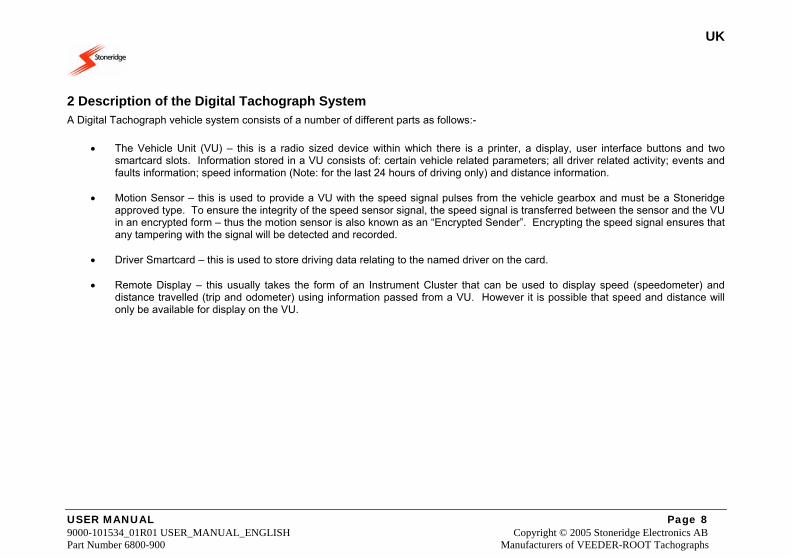
2 Description of the Digital Tachograph System A Digital Tachograph vehicle system consists of a number of different parts as follows:-
• The Vehicle Unit (VU) – this is a radio sized device within which there is a printer, a display, user interface buttons and two smartcard slots. Information stored in a VU consists of: certain vehicle related parameters; all driver related activity; events and faults information; speed information (Note: for the last 24 hours of driving only) and distance information.
• Motion Sensor – this is used to provide a VU with the speed signal pulses from the vehicle gearbox and must be a Stoneridge
approved type. To ensure the integrity of the speed sensor signal, the speed signal is transferred between the sensor and the VU in an encrypted form – thus the motion sensor is also known as an “Encrypted Sender”. Encrypting the speed signal ensures that any tampering with the signal will be detected and recorded.
• Driver Smartcard – this is used to store driving data relating to the named driver on the card.
• Remote Display – this usually takes the form of an Instrument Cluster that can be used to display speed (speedometer) and
distance travelled (trip and odometer) using information passed from a VU. However it is possible that speed and distance will only be available for display on the VU.
UK
USER MANUAL Page 9 9000-101534_01R01 USER_MANUAL_ENGLISH Copyright © 2005 Stoneridge Electronics AB Part Number 6800-900 Manufacturers of VEEDER-ROOT Tachographs
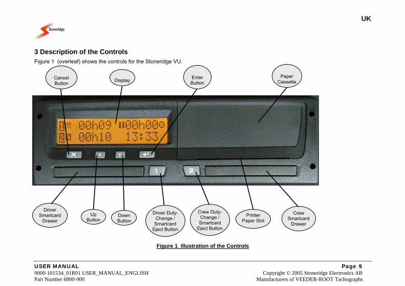
3 Description of the Controls Figure 1 (overleaf) shows the controls for the Stoneridge VU.
Figure 1 Illustration of the Controls
Paper
Cassette
Driver Smartcard
Drawer Down Button
Driver Duty-Change / Smartcard
Eject Button
Display
Cancel Button
Up Button
Crew Smartcard
Drawer
Crew Duty-Change / Smartcard
Eject Button
EnterButton
Printer Paper Slot
UK
USER MANUAL Page 10 9000-101534_01R01 USER_MANUAL_ENGLISH Copyright © 2005 Stoneridge Electronics AB Part Number 6800-900 Manufacturers of VEEDER-ROOT Tachographs
3.1 Driver Duty-Change / Smartcard Eject Buttons These buttons (one for driver and one for crew) have the dual functionality of being used firstly to change the currently selected duty and secondly for ejecting the associated smartcard drawer.
3.1.1 Duty Change Function
Two individual buttons are provided, respectively for the driver and crew (if two drivers are present), for initiating a period of recorded duty. The Driver and is allocated the left hand Duty-change button (“1”), while the Crew and is allocated the right hand Duty-change button (“2”). The duty mode for the Driver or the Crew is selected by ‘short’ pressing the appropriate Duty-change button (see section 4.4 Duty Setting, for a more extensive description). In order to change the mode of activity, the Driver or Crew will press their respective Duty-change button a number of times, until the correct mode of duty is displayed (Note: top line for Driver and bottom line for Crew). It should be noted that when a vehicle begins to move, the VU automatically switches the Driver duty mode to ‘drive’ and the Crew duty mode to ‘available’. When a vehicle stops moving, the Driver duty automatically changes to ‘work’ and the Crew duty will remain at ‘available’. Please note that ‘rest’ mode for both Driver and Crew, ‘available’ mode for the Driver and ‘work’ mode for the Crew all must be explicitly selected.
3.1.2 Smartcard Eject Function
The Driver Duty-Change buttons also have an alternative function in that they can be used to eject the smartcard drawers in order to insert or remove a smartcard (Note: left hand ‘1’ button for Driver smartcard and right hand ‘2’ button for Crew smartcard). To eject a smartcard drawer ‘long-press’ the appropriate button. After a short while the required drawer will latch open. Notes: 1. If a smartcard is inserted in a VU, the associated Eject button is only active when the vehicle is stationary. 2. The Eject buttons are not active when the electrical supply to the VU is interrupted. If it is not possible to restore the power, the drawer will require to be released by a Tachograph Workshop.
3.2 Enter Button The Enter button is pressed to enter the Main Menu of sub-functions whilst the standard Driving Mode screen (or one of the page selection alternatives) is displayed. The button also has the alternative function of being used to confirm selectable options as displayed in the various main menu sub-function screens and Manual duty entry screens etc (as explained throughout the manual). Finally, the Enter button can be used to acknowledge and clear warning messages.
UK
USER MANUAL Page 11 9000-101534_01R01 USER_MANUAL_ENGLISH Copyright © 2005 Stoneridge Electronics AB Part Number 6800-900 Manufacturers of VEEDER-ROOT Tachographs
3.3 Cancel Button The Cancel button is used for returning to the main menu and driving mode screens.
3.4 Up / Down Buttons The Up / Down buttons are used to scroll through the various menu options or to increment or decrement displayed values e.g. hours.
3.5 Smartcard Drawers The Driver (left hand side) and Crew (right hand side) smartcard drawers are used to insert (or remove) smartcards into a VU, as explained in section 3.1.2 Smartcard Eject Function.
3.6 Paper Cassette The paper cassette is used to house the paper roll. The paper cassette should remain closed at all times except when fitting a new paper roll. When taking a printout, the paper will emerge from the slot at the bottom of the cassette and consequently the slot must be kept free from obstructions.
UK
USER MANUAL Page 12 9000-101534_01R01 USER_MANUAL_ENGLISH Copyright © 2005 Stoneridge Electronics AB Part Number 6800-900 Manufacturers of VEEDER-ROOT Tachographs
3.6.1 Printer Paper Insertion
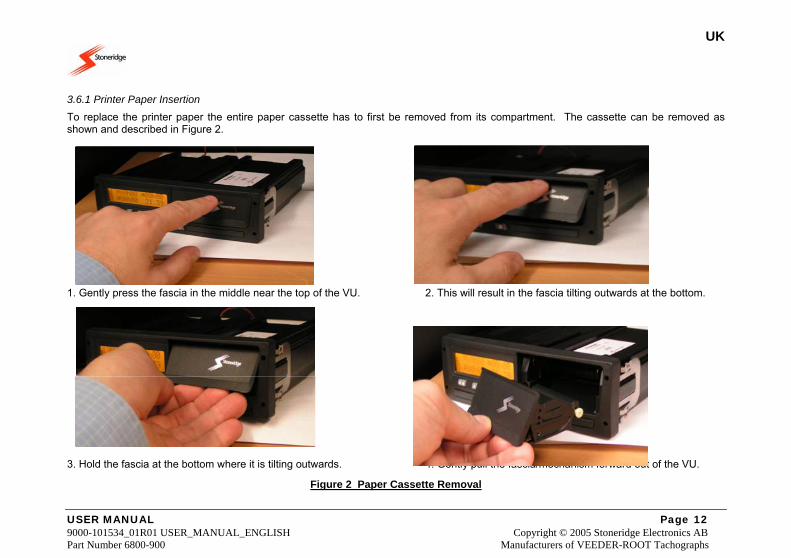
To replace the printer paper the entire paper cassette has to first be removed from its compartment. The cassette can be removed as shown and described in Figure 2.
1. Gently press the fascia in the middle near the top of the VU. 2. This will result in the fascia tilting outwards at the bottom. 3. Hold the fascia at the bottom where it is tilting outwards. 4. Gently pull the fascia/mechanism forward out of the VU.
Figure 2 Paper Cassette Removal
UK
USER MANUAL Page 13 9000-101534_01R01 USER_MANUAL_ENGLISH Copyright © 2005 Stoneridge Electronics AB Part Number 6800-900 Manufacturers of VEEDER-ROOT Tachographs
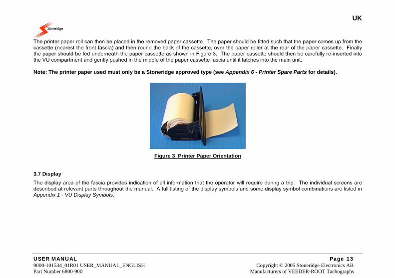
The printer paper roll can then be placed in the removed paper cassette. The paper should be fitted such that the paper comes up from the cassette (nearest the front fascia) and then round the back of the cassette, over the paper roller at the rear of the paper cassette. Finally the paper should be fed underneath the paper cassette as shown in Figure 3. The paper cassette should then be carefully re-inserted into the VU compartment and gently pushed in the middle of the paper cassette fascia until it latches into the main unit. Note: The printer paper used must only be a Stoneridge approved type (see Appendix 6 - Printer Spare Parts for details).
Figure 3 Printer Paper Orientation
3.7 Display The display area of the fascia provides indication of all information that the operator will require during a trip. The individual screens are described at relevant parts throughout the manual. A full listing of the display symbols and some display symbol combinations are listed in Appendix 1 - VU Display Symbols.
UK
USER MANUAL Page 14 9000-101534_01R01 USER_MANUAL_ENGLISH Copyright © 2005 Stoneridge Electronics AB Part Number 6800-900 Manufacturers of VEEDER-ROOT Tachographs
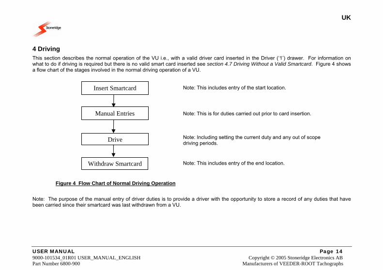
4 Driving This section describes the normal operation of the VU i.e., with a valid driver card inserted in the Driver (‘1’) drawer. For information on what to do if driving is required but there is no valid smart card inserted see section 4.7 Driving Without a Valid Smartcard. Figure 4 shows a flow chart of the stages involved in the normal driving operation of a VU. Note: This includes entry of the start location. Note: This is for duties carried out prior to card insertion. Note: Including setting the current duty and any out of scope driving periods. Note: This includes entry of the end location.
Figure 4 Flow Chart of Normal Driving Operation
Note: The purpose of the manual entry of driver duties is to provide a driver with the opportunity to store a record of any duties that have been carried since their smartcard was last withdrawn from a VU.
Insert Smartcard
Manual Entries
Drive
Withdraw Smartcard
UK
USER MANUAL Page 15 9000-101534_01R01 USER_MANUAL_ENGLISH Copyright © 2005 Stoneridge Electronics AB Part Number 6800-900 Manufacturers of VEEDER-ROOT Tachographs
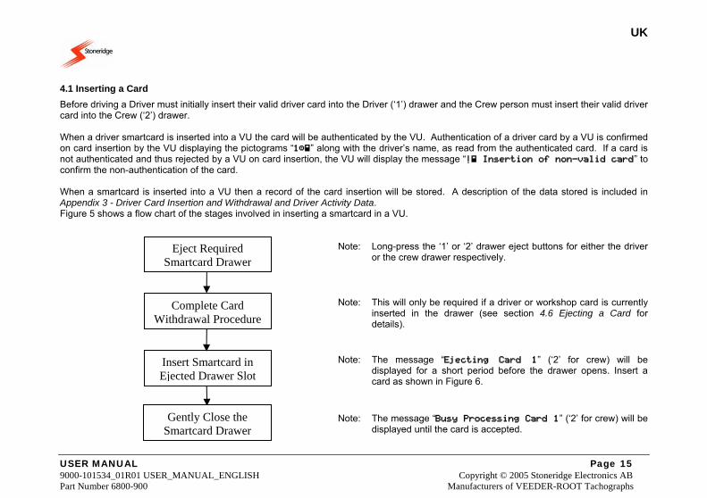
4.1 Inserting a Card Before driving a Driver must initially insert their valid driver card into the Driver (‘1’) drawer and the Crew person must insert their valid driver card into the Crew (‘2’) drawer. When a driver smartcard is inserted into a VU the card will be authenticated by the VU. Authentication of a driver card by a VU is confirmed on card insertion by the VU displaying the pictograms “1” along with the driver’s name, as read from the authenticated card. If a card is not authenticated and thus rejected by a VU on card insertion, the VU will display the message “! Insertion of non-valid card” to confirm the non-authentication of the card. When a smartcard is inserted into a VU then a record of the card insertion will be stored. A description of the data stored is included in Appendix 3 - Driver Card Insertion and Withdrawal and Driver Activity Data. Figure 5 shows a flow chart of the stages involved in inserting a smartcard in a VU. Note: Long-press the ‘1’ or ‘2’ drawer eject buttons for either the driver
or the crew drawer respectively. Note: This will only be required if a driver or workshop card is currently
inserted in the drawer (see section 4.6 Ejecting a Card for details).
Note: The message “Ejecting Card 1” (‘2’ for crew) will be
displayed for a short period before the drawer opens. Insert a card as shown in Figure 6.
Note: The message “Busy Processing Card 1” (‘2’ for crew) will be displayed until the card is accepted.
Complete Card Withdrawal Procedure
Insert Smartcard in Ejected Drawer Slot
Gently Close the Smartcard Drawer
Eject Required Smartcard Drawer
UK
USER MANUAL Page 16 9000-101534_01R01 USER_MANUAL_ENGLISH Copyright © 2005 Stoneridge Electronics AB Part Number 6800-900 Manufacturers of VEEDER-ROOT Tachographs
Figure 5 Flow Chart of Smartcard Insertion Procedure
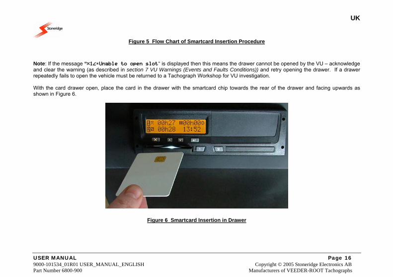
Note: If the message “1Unable to open slot“ is displayed then this means the drawer cannot be opened by the VU – acknowledge and clear the warning (as described in section 7 VU Warnings (Events and Faults Conditions)) and retry opening the drawer. If a drawer repeatedly fails to open the vehicle must be returned to a Tachograph Workshop for VU investigation. With the card drawer open, place the card in the drawer with the smartcard chip towards the rear of the drawer and facing upwards as shown in Figure 6.
Figure 6 Smartcard Insertion in Drawer
UK
USER MANUAL Page 17 9000-101534_01R01 USER_MANUAL_ENGLISH Copyright © 2005 Stoneridge Electronics AB Part Number 6800-900 Manufacturers of VEEDER-ROOT Tachographs
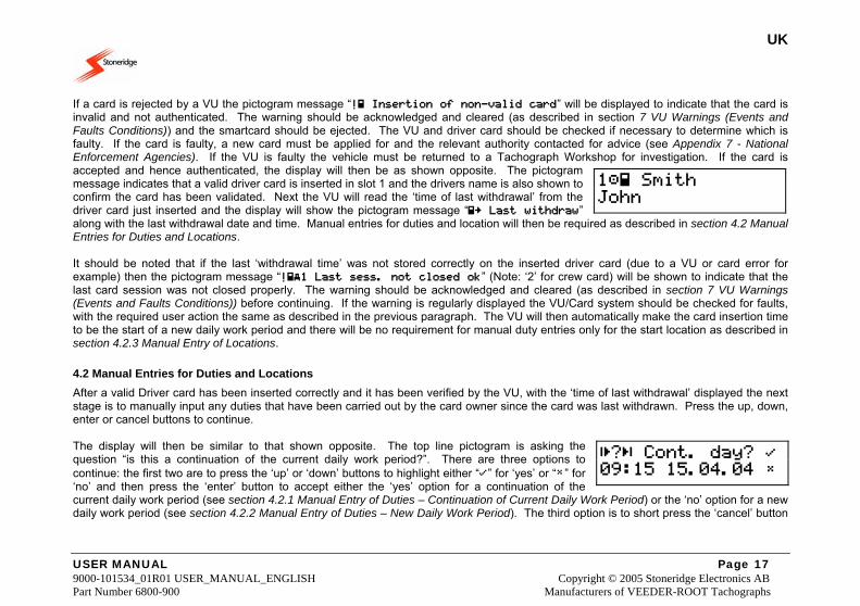
If a card is rejected by a VU the pictogram message “! Insertion of non-valid card” will be displayed to indicate that the card is invalid and not authenticated. The warning should be acknowledged and cleared (as described in section 7 VU Warnings (Events and Faults Conditions)) and the smartcard should be ejected. The VU and driver card should be checked if necessary to determine which is faulty. If the card is faulty, a new card must be applied for and the relevant authority contacted for advice (see Appendix 7 - National Enforcement Agencies). If the VU is faulty the vehicle must be returned to a Tachograph Workshop for investigation. If the card is accepted and hence authenticated, the display will then be as shown opposite. The pictogram message indicates that a valid driver card is inserted in slot 1 and the drivers name is also shown to confirm the card has been validated. Next the VU will read the ‘time of last withdrawal’ from the driver card just inserted and the display will show the pictogram message “ Last withdraw” along with the last withdrawal date and time. Manual entries for duties and location will then be required as described in section 4.2 Manual Entries for Duties and Locations. It should be noted that if the last ‘withdrawal time’ was not stored correctly on the inserted driver card (due to a VU or card error for example) then the pictogram message “!1 Last sess. not closed ok” (Note: ‘2’ for crew card) will be shown to indicate that the last card session was not closed properly. The warning should be acknowledged and cleared (as described in section 7 VU Warnings (Events and Faults Conditions)) before continuing. If the warning is regularly displayed the VU/Card system should be checked for faults, with the required user action the same as described in the previous paragraph. The VU will then automatically make the card insertion time to be the start of a new daily work period and there will be no requirement for manual duty entries only for the start location as described in section 4.2.3 Manual Entry of Locations.
4.2 Manual Entries for Duties and Locations After a valid Driver card has been inserted correctly and it has been verified by the VU, with the ‘time of last withdrawal’ displayed the next stage is to manually input any duties that have been carried out by the card owner since the card was last withdrawn. Press the up, down, enter or cancel buttons to continue. The display will then be similar to that shown opposite. The top line pictogram is asking the question “is this a continuation of the current daily work period?”. There are three options to continue: the first two are to press the ‘up’ or ‘down’ buttons to highlight either “” for ‘yes’ or “” for ‘no’ and then press the ‘enter’ button to accept either the ‘yes’ option for a continuation of the current daily work period (see section 4.2.1 Manual Entry of Duties – Continuation of Current Daily Work Period) or the ‘no’ option for a new daily work period (see section 4.2.2 Manual Entry of Duties – New Daily Work Period). The third option is to short press the ‘cancel’ button
1 Smith John
? Cont. day? 09:15 15.04.04
UK
USER MANUAL Page 18 9000-101534_01R01 USER_MANUAL_ENGLISH Copyright © 2005 Stoneridge Electronics AB Part Number 6800-900 Manufacturers of VEEDER-ROOT Tachographs
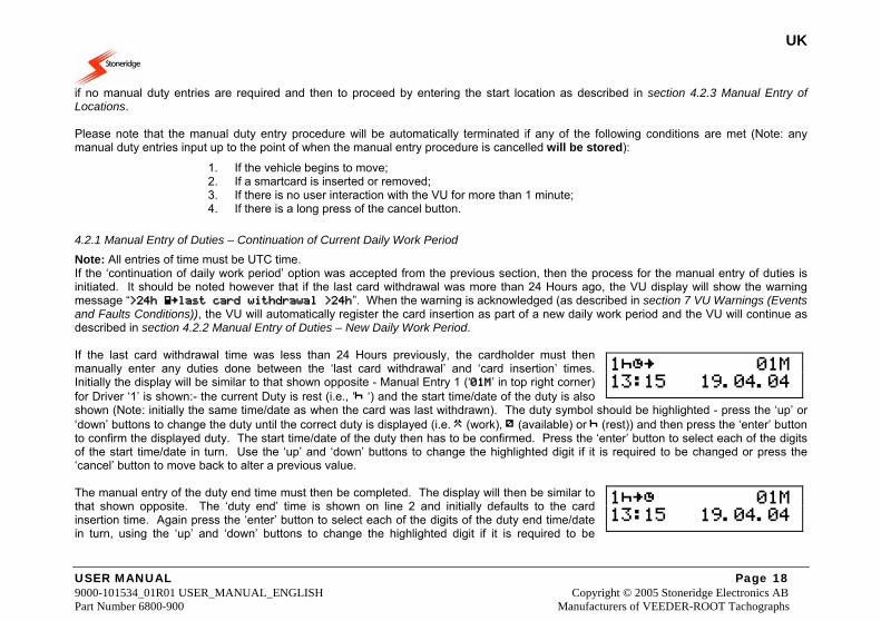
if no manual duty entries are required and then to proceed by entering the start location as described in section 4.2.3 Manual Entry of Locations. Please note that the manual duty entry procedure will be automatically terminated if any of the following conditions are met (Note: any manual duty entries input up to the point of when the manual entry procedure is cancelled will be stored):
1. If the vehicle begins to move; 2. If a smartcard is inserted or removed; 3. If there is no user interaction with the VU for more than 1 minute; 4. If there is a long press of the cancel button.
4.2.1 Manual Entry of Duties – Continuation of Current Daily Work Period
Note: All entries of time must be UTC time. If the ‘continuation of daily work period’ option was accepted from the previous section, then the process for the manual entry of duties is initiated. It should be noted however that if the last card withdrawal was more than 24 Hours ago, the VU display will show the warning message “>24h last card withdrawal >24h”. When the warning is acknowledged (as described in section 7 VU Warnings (Events and Faults Conditions)), the VU will automatically register the card insertion as part of a new daily work period and the VU will continue as described in section 4.2.2 Manual Entry of Duties – New Daily Work Period. If the last card withdrawal time was less than 24 Hours previously, the cardholder must then manually enter any duties done between the ‘last card withdrawal’ and ‘card insertion’ times. Initially the display will be similar to that shown opposite - Manual Entry 1 (‘01M’ in top right corner) for Driver ‘1’ is shown:- the current Duty is rest (i.e., ‘ ‘) and the start time/date of the duty is also shown (Note: initially the same time/date as when the card was last withdrawn). The duty symbol should be highlighted - press the ‘up’ or ‘down’ buttons to change the duty until the correct duty is displayed (i.e. (work), (available) or (rest)) and then press the ‘enter’ button to confirm the displayed duty. The start time/date of the duty then has to be confirmed. Press the ‘enter’ button to select each of the digits of the start time/date in turn. Use the ‘up’ and ‘down’ buttons to change the highlighted digit if it is required to be changed or press the ‘cancel’ button to move back to alter a previous value. The manual entry of the duty end time must then be completed. The display will then be similar to that shown opposite. The ‘duty end’ time is shown on line 2 and initially defaults to the card insertion time. Again press the ‘enter’ button to select each of the digits of the duty end time/date in turn, using the ‘up’ and ‘down’ buttons to change the highlighted digit if it is required to be
1 01M 13:15 19.04.04
1 01M 13:15 19.04.04
UK
USER MANUAL Page 19 9000-101534_01R01 USER_MANUAL_ENGLISH Copyright © 2005 Stoneridge Electronics AB Part Number 6800-900 Manufacturers of VEEDER-ROOT Tachographs
changed or press the ‘cancel’ button to move back to re-edit a value. If the duty end ‘time/date’ is not the card insertion time, then when the end time/date is accepted, the display will automatically update for the manual entry of the next duty. The Manual Duty Counter (top right corner) will be incremented (i.e. ‘02M’ then ‘03M’ etc) and the start ‘time/date’ will be the same as the end time for the previous duty. The next duty and the start and end time/date for the next manual duty entry have to be confirmed using the same method as above. Please note that only up to a maximum of 16 manual duty entries is possible, attempting to enter more than this will result in the warning message “M.....! Memory Full!” being displayed. The warning should be acknowledged and cleared (as described in section 7 VU Warnings (Events and Faults Conditions)) before continuing. This process of manually entering driver duties has to be repeated for all duties up to the card insertion time. When the last manual duty entry has been confirmed (i.e., the end time of the duty is the card insertion time or the number of manual duties entered is 16) then the opportunity to check or modify the manual entry of duties will be given as described in the next section.
4.2.1.1 Manual Entry of Duties – Modification of Entries
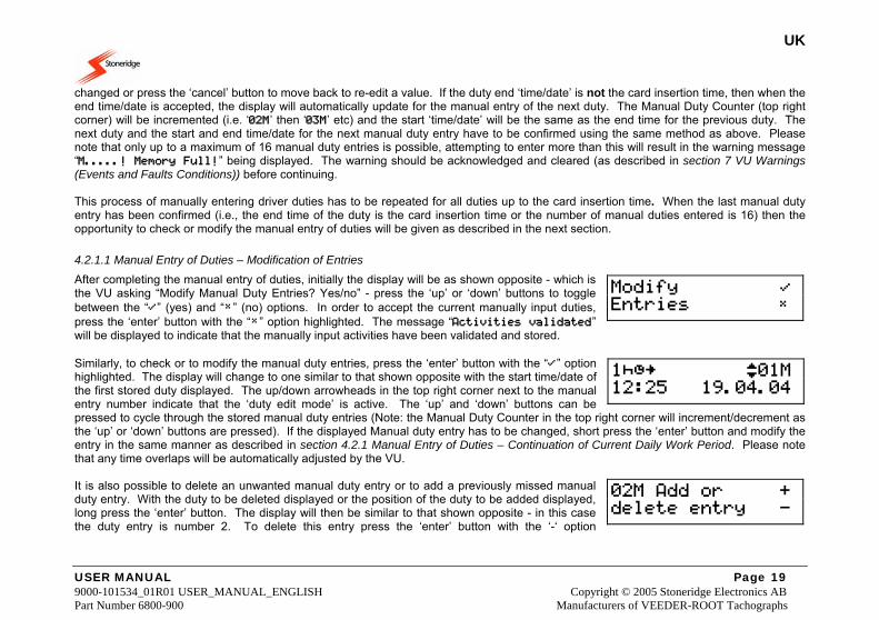
After completing the manual entry of duties, initially the display will be as shown opposite - which is the VU asking “Modify Manual Duty Entries? Yes/no” - press the ‘up’ or ‘down’ buttons to toggle between the “” (yes) and “” (no) options. In order to accept the current manually input duties, press the ‘enter’ button with the “” option highlighted. The message “Activities validated” will be displayed to indicate that the manually input activities have been validated and stored. Similarly, to check or to modify the manual duty entries, press the ‘enter’ button with the “” option highlighted. The display will change to one similar to that shown opposite with the start time/date of the first stored duty displayed. The up/down arrowheads in the top right corner next to the manual entry number indicate that the ‘duty edit mode’ is active. The ‘up’ and ‘down’ buttons can be pressed to cycle through the stored manual duty entries (Note: the Manual Duty Counter in the top right corner will increment/decrement as the ‘up’ or ‘down’ buttons are pressed). If the displayed Manual duty entry has to be changed, short press the ‘enter’ button and modify the entry in the same manner as described in section 4.2.1 Manual Entry of Duties – Continuation of Current Daily Work Period. Please note that any time overlaps will be automatically adjusted by the VU. It is also possible to delete an unwanted manual duty entry or to add a previously missed manual duty entry. With the duty to be deleted displayed or the position of the duty to be added displayed, long press the ‘enter’ button. The display will then be similar to that shown opposite - in this case the duty entry is number 2. To delete this entry press the ‘enter’ button with the ‘-‘ option
Modify Entries
1 01M 12:25 19.04.04
02M Add or + delete entry -
UK
USER MANUAL Page 20 9000-101534_01R01 USER_MANUAL_ENGLISH Copyright © 2005 Stoneridge Electronics AB Part Number 6800-900 Manufacturers of VEEDER-ROOT Tachographs
highlighted or to add a new ‘02’ entry (assuming that less than 16 duties are currently entered) press the ‘enter’ button with the ‘+’ option highlighted (Note: press the ‘up’ or ‘down’ buttons to toggle between ‘+’ and ‘-‘ options). If a duty entry is added (Note: use the same method for duty entry as described in section 4.2.1 Manual Entry of Duties – Continuation of Current Daily Work Period) then this may create a time overlap between duty entries and the VU will then automatically adjust to ensure no time overlap occurs. Once all of the Manual Duty entries have been checked/altered, press the ‘cancel’ button to return to the “Modify Manual Duty Entries? Yes/No” screen previously described above, and then select the no (‘’) option to validate the Manual Entry of duties (Note: the message “Activities validated” will be displayed to confirm validation).
4.2.2 Manual Entry of Duties – New Daily Work Period
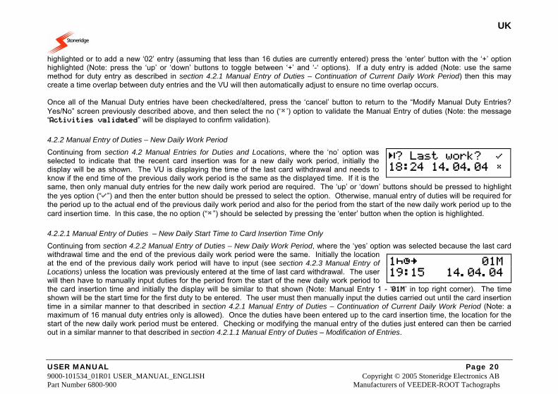
Continuing from section 4.2 Manual Entries for Duties and Locations, where the ‘no’ option was selected to indicate that the recent card insertion was for a new daily work period, initially the display will be as shown. The VU is displaying the time of the last card withdrawal and needs to know if the end time of the previous daily work period is the same as the displayed time. If it is the same, then only manual duty entries for the new daily work period are required. The ‘up’ or ‘down’ buttons should be pressed to highlight the yes option (“”) and then the enter button should be pressed to select the option. Otherwise, manual entry of duties will be required for the period up to the actual end of the previous daily work period and also for the period from the start of the new daily work period up to the card insertion time. In this case, the no option (“”) should be selected by pressing the ‘enter’ button when the option is highlighted.
4.2.2.1 Manual Entry of Duties – New Daily Start Time to Card Insertion Time Only
Continuing from section 4.2.2 Manual Entry of Duties – New Daily Work Period, where the ‘yes’ option was selected because the last card withdrawal time and the end of the previous daily work period were the same. Initially the location at the end of the previous daily work period will have to input (see section 4.2.3 Manual Entry of Locations) unless the location was previously entered at the time of last card withdrawal. The user will then have to manually input duties for the period from the start of the new daily work period to the card insertion time and initially the display will be similar to that shown (Note: Manual Entry 1 - ‘01M’ in top right corner). The time shown will be the start time for the first duty to be entered. The user must then manually input the duties carried out until the card insertion time in a similar manner to that described in section 4.2.1 Manual Entry of Duties – Continuation of Current Daily Work Period (Note: a maximum of 16 manual duty entries only is allowed). Once the duties have been entered up to the card insertion time, the location for the start of the new daily work period must be entered. Checking or modifying the manual entry of the duties just entered can then be carried out in a similar manner to that described in section 4.2.1.1 Manual Entry of Duties – Modification of Entries.
? Last work? 18:24 14.04.04
1 01M 19:15 14.04.04
UK
USER MANUAL Page 21 9000-101534_01R01 USER_MANUAL_ENGLISH Copyright © 2005 Stoneridge Electronics AB Part Number 6800-900 Manufacturers of VEEDER-ROOT Tachographs
4.2.2.2 Manual Entry of Duties – Last Card Withdrawal to Daily Work Period End & New Daily Start to Card Insertion
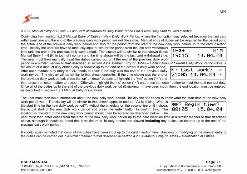
Continuing from section 4.2.2 Manual Entry of Duties – New Daily Work Period, where the ‘no’ option was selected because the last card withdrawal time and the end of the previous daily work period are not the same. Manual entry of duties will be required for the period up to the actual end of the previous daily work period and also for the period from the start of the new daily work period up to the card insertion time. Initially the user will have to manually input duties for the period from the last card withdrawal time until the end of the previous daily work period. The display will be similar to that shown (Note: Manual Entry 1 - ‘01M’ in top right corner) and the time shown will be the last card withdrawal time. The user must then manually input the duties carried out until the end of the previous daily work period in a similar manner to that described in section 4.2.1 Manual Entry of Duties – Continuation of Current Daily Work Period (Note: a maximum of 8 manual duty entries only is allowed up to the end of the previous daily work period). After each manual duty entry the VU needs to know if the duty was the end of the previous daily work period. The display will be similar to that shown opposite. If the time shown was the end of the previous daily work period, press the ‘up’ or ‘down’ buttons to highlight the ‘yes’ option (“”) and then press the ‘enter’ button to accept. Otherwise highlight the ‘no’ option (“”) and press the ‘enter’ button to input the next manual duty. Once all of the duties up to the end of the previous daily work period (8 maximum) have been input, then the end location must be entered, as described in section 4.2.3 Manual Entry of Locations. The user must then input information about the new daily work period. Initially the VU needs to know what the start time of the new daily work period was. The display will be similar to that shown opposite and the VU is asking “What is the start time for the new daily work period?”. Adjust the time/date on the second line until it shows the actual start of the new daily work period and press the ‘enter’ button to confirm this. The location for the start of the new daily work period should then be entered as described below. The user must then enter duties from the start of the new daily work period up to the card insertion time in a similar manner to that described above, although it should be noted that a maximum of 16 duty entries are allowed including any duties just entered up to the end of the previous daily work period. It should again be noted that once all the duties have been input up to the card insertion time, checking or modifying of the manual entry of the duties can be carried out in a similar manner to that described in section 4.2.1.1 Manual Entry of Duties – Modification of Entries.
1 01M 19:15 14.04.04
? Last work? 21:05 14.04.04
? Begin time? 08:05 15.04.04
UK
USER MANUAL Page 22 9000-101534_01R01 USER_MANUAL_ENGLISH Copyright © 2005 Stoneridge Electronics AB Part Number 6800-900 Manufacturers of VEEDER-ROOT Tachographs
4.2.3 Manual Entry of Locations
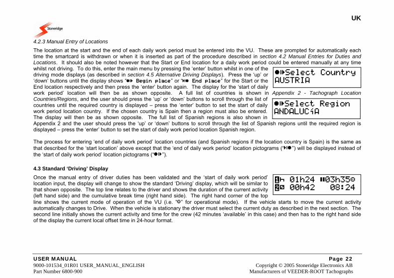
The location at the start and the end of each daily work period must be entered into the VU. These are prompted for automatically each time the smartcard is withdrawn or when it is inserted as part of the procedure described in section 4.2 Manual Entries for Duties and Locations. It should also be noted however that the Start or End location for a daily work period could be entered manually at any time whilst not driving. To do this, enter the main menu by pressing the ‘enter’ button whilst in one of the driving mode displays (as described in section 4.5 Alternative Driving Displays). Press the ‘up’ or ‘down’ buttons until the display shows “ Begin place” or “ End place” for the Start or the End location respectively and then press the ‘enter’ button again. The display for the ‘start of daily work period’ location will then be as shown opposite. A full list of countries is shown in Appendix 2 - Tachograph Location Countries/Regions, and the user should press the ‘up’ or ‘down’ buttons to scroll through the list of countries until the required country is displayed – press the ‘enter’ button to set the start of daily work period location country. If the chosen country is Spain then a region must also be entered. The display will then be as shown opposite. The full list of Spanish regions is also shown in Appendix 2 and the user should press the ‘up’ or ‘down’ buttons to scroll through the list of Spanish regions until the required region is displayed – press the ‘enter’ button to set the start of daily work period location Spanish region. The process for entering ‘end of daily work period’ location countries (and Spanish regions if the location country is Spain) is the same as that described for the ‘start location’ above except that the ‘end of daily work period’ location pictograms (“”) will be displayed instead of the ‘start of daily work period’ location pictograms (“”).
4.3 Standard ‘Driving’ Display Once the manual entry of driver duties has been validated and the ‘start of daily work period’ location input, the display will change to show the standard ‘Driving’ display, which will be similar to that shown opposite. The top line relates to the driver and shows the duration of the current activity (left hand side) and the cumulative break time (right hand side). The right hand corner of the top line shows the current mode of operation of the VU (i.e. ”” for operational mode). If the vehicle starts to move the current activity automatically changes to Drive. When the vehicle is stationary the driver must select the current duty as described in the next section. The second line initially shows the current activity and time for the crew (42 minutes ‘available’ in this case) and then has to the right hand side of the display the current local offset time in 24-hour format.
Select Region ANDALUCíA
Select Country AUSTRIA
01h24 03h35 00h42 08:24
UK
USER MANUAL Page 23 9000-101534_01R01 USER_MANUAL_ENGLISH Copyright © 2005 Stoneridge Electronics AB Part Number 6800-900 Manufacturers of VEEDER-ROOT Tachographs
4.4 Duty Setting
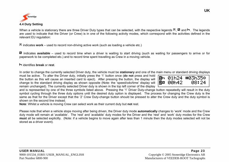
When a vehicle is stationary there are three Driver Duty types that can be selected, with the respective legends , and . The legends are used to indicate that the Driver (or Crew) is in one of the following activity modes, which correspond with the activities defined in the relevant EU regulation: indicates work – used to record non-driving active work (such as loading a vehicle etc.) indicates available – used to record time when a driver is waiting to start driving (such as waiting for passengers to arrive or for paperwork to be completed etc.) and to record time spent travelling as Crew in a moving vehicle. identifies break or rest. In order to change the currently selected Driver duty, the vehicle must be stationary and one of the main menu or standard driving displays must be active. To alter the Driver duty, initially press the ‘1’ button once (do not press and hold the button as this will cause an inserted card to eject). After pressing the button, the display will change to the standard driving display as shown opposite (Note: the ‘speed/odo/time’ display will remain unchanged). The currently selected Driver duty is shown in the top left corner of the display and is represented by one of the three symbols listed above. Pressing the ‘1’ Driver Duty-change button repeatedly will result in the duty symbol cycling through the three duty options until the desired duty option is displayed. The process for changing the Crew duty is the same as that for the Driver except that the ‘2’ Crew Duty-change button should be pressed to alter the Crew duty and the duty symbol is shown on the second line instead. Note: Whilst a vehicle is moving Crew can select work as their current duty but not rest. Please note that when a vehicle stops moving after being driven, the Driver duty mode automatically changes to ‘work’ mode and the Crew duty mode will remain at ‘available’. The ‘rest’ and ‘available’ duty modes for the Driver and the ‘rest’ and ‘work’ duty modes for the Crew must all be selected explicitly. (Note: if a vehicle begins to move again after less than 1 minute then the duty modes selected will not be stored as a driver event).
01h24 03h35 00h42 08:24
UK
USER MANUAL Page 24 9000-101534_01R01 USER_MANUAL_ENGLISH Copyright © 2005 Stoneridge Electronics AB Part Number 6800-900 Manufacturers of VEEDER-ROOT Tachographs
4.5 Alternative Driving Displays Once the vehicle starts to move the Driver duty automatically changes to ‘drive’ and the display will usually be as shown in section 4.3 Standard ‘Driving’ Display. If the ‘Standard Driving Display’ is not shown, press the ‘cancel’ button to return to it. There are 4 other displays that may be selected whilst driving, using the up or down buttons to scroll through the screens. For a full description of the alternative screens see Appendix 5 - Display Screens Selectable Whilst Driving. Whilst driving it is possible that Driver warnings will be periodically displayed – please see section 7 VU Warnings (Events and Faults Conditions) for a full list of possible warnings and details of how to acknowledge and clear warning messages.
4.5.1 Out of Scope Driving
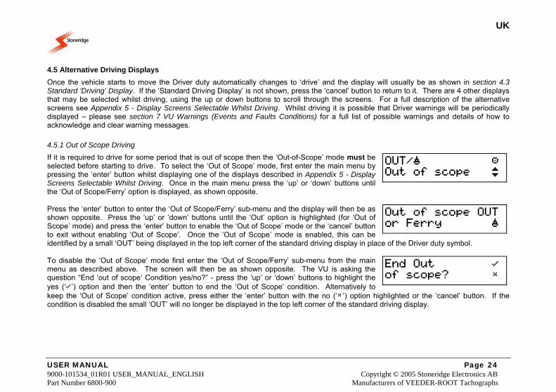
If it is required to drive for some period that is out of scope then the ‘Out-of-Scope’ mode must be selected before starting to drive. To select the ‘Out of Scope’ mode, first enter the main menu by pressing the ‘enter’ button whilst displaying one of the displays described in Appendix 5 - Display Screens Selectable Whilst Driving. Once in the main menu press the ‘up’ or ‘down’ buttons until the ‘Out of Scope/Ferry’ option is displayed, as shown opposite. Press the ‘enter’ button to enter the ‘Out of Scope/Ferry’ sub-menu and the display will then be as shown opposite. Press the ‘up’ or ‘down’ buttons until the ‘Out’ option is highlighted (for ‘Out of Scope’ mode) and press the ‘enter’ button to enable the ‘Out of Scope’ mode or the ‘cancel’ button to exit without enabling ‘Out of Scope’. Once the ‘Out of Scope’ mode is enabled, this can be identified by a small ‘OUT’ being displayed in the top left corner of the standard driving display in place of the Driver duty symbol. To disable the ‘Out of Scope’ mode first enter the ‘Out of Scope/Ferry’ sub-menu from the main menu as described above. The screen will then be as shown opposite. The VU is asking the question “End ‘out of scope’ Condition yes/no?” - press the ‘up’ or ‘down’ buttons to highlight the yes (‘’) option and then the ‘enter’ button to end the ‘Out of Scope’ condition. Alternatively to keep the ‘Out of Scope’ condition active, press either the ‘enter’ button with the no (‘’) option highlighted or the ‘cancel’ button. If the condition is disabled the small ‘OUT’ will no longer be displayed in the top left corner of the standard driving display.
OUT/ Out of scope
Out of scope OUT or Ferry
End Out of scope?
UK
USER MANUAL Page 25 9000-101534_01R01 USER_MANUAL_ENGLISH Copyright © 2005 Stoneridge Electronics AB Part Number 6800-900 Manufacturers of VEEDER-ROOT Tachographs
4.5.2 Ferry/Train Crossing Mode Selection
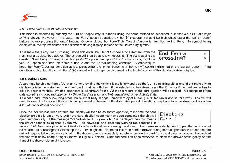
This mode is selected by entering the ‘Out of Scope/Ferry’ sub-menu using the same method as described in section 4.5.1 Out of Scope Driving above. However in this case, the ‘Ferry’ option (identified by the ‘’ pictogram) should be highlighted using the ‘up’ or ‘down’ buttons before pressing the ‘enter’ button. Once enabled, the ‘Ferry/Train Crossing’ mode is identified by the ‘Ferry’ () symbol being displayed in the top left corner of the standard driving display in place of the Driver duty symbol. To disable the ‘Ferry/Train Crossing’ mode first enter the ‘Out of Scope/Ferry’ sub-menu from the main menu as described above. The screen will then be as shown opposite. The VU is asking the question “End ‘Ferry/Crossing’ Condition yes/no?” - press the ‘up’ or ‘down’ buttons to highlight the yes (‘’) option and then the ‘enter’ button to end the ‘Ferry/Crossing’ condition. Alternatively to keep the ‘Ferry/Crossing’ condition active, press either the ‘enter’ button with the no (‘’) option highlighted or the ‘cancel’ button. If the condition is disabled, the small ‘Ferry’ () symbol will no longer be displayed in the top left corner of the standard driving display.
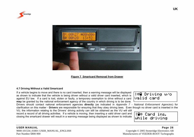
4.6 Ejecting a Card A card may be ejected from a VU at any time providing the vehicle is stationary and also the VU is displaying either one of the main driving displays or is in the main menu. A driver card must be withdrawn if the vehicle is to be driven by another Driver or if the card owner has to drive in another vehicle. When a smartcard is withdrawn from a VU then a record of the card ejection will be stored. A description of the data stored is included in Appendix 3 - Driver Card Insertion and Withdrawal and Driver Activity Data. To eject a card from a VU, long-press the relevant Duty-change / smartcard eject button (i.e. ‘1’ for Driver and ‘2’ for Crew). The VU will need to know the location if the card is being ejected at the end of the daily drive period. Locations may be entered as described in section 4.2.3 Manual Entry of Locations. Once the location has been entered, the display will then be as shown opposite, to indicate the card ejection process is under way. After the card ejection sequence has been completed the slot will open automatically. If the message “1Unable to open slot“ is displayed then this means the drawer cannot be opened by the VU – acknowledge and clear the warning (as described in section 7 VU Warnings (Events and Faults Conditions)) and retry opening the drawer. If a drawer repeatedly fails to open the vehicle must be returned to a Tachograph Workshop for VU investigation. Repeated failure to open a drawer during normal operation will mean that the unit will require to be decommissioned. If the drawer opens successfully, carefully remove the card from the drawer by popping the card out the slot from below using a finger (shown in Figure 7 below). Once the card has been removed, to close the drawer press gently on the front of the drawer slot until it latches.
End Ferry crossing?
Ejecting Card 1
UK
USER MANUAL Page 26 9000-101534_01R01 USER_MANUAL_ENGLISH Copyright © 2005 Stoneridge Electronics AB Part Number 6800-900 Manufacturers of VEEDER-ROOT Tachographs
Figure 7 Smartcard Removal from Drawer
4.7 Driving Without a Valid Smartcard If a vehicle begins to move and there is no card inserted, then a warning message will be displayed as shown to indicate that the vehicle is being driven without a valid driver card inserted, which is against EU law. If a card is lost, stolen or faulty, a temporary exemption to drive without a card may be granted by the national enforcement agency of the country in which driving is to be done. Drivers should contact national enforcement agencies directly (as indicated in Appendix 7 - National Enforcement Agencies) for clarification on this matter - Drivers are responsible for ensuring that they obey driving laws. Even though no driver card is inserted in the VU, the information relating to the Drivers’ driving activity can still be obtained as the VU will still record a record of all driving activities. If a vehicle is moving, then inserting a valid driver card and closing the smartcard drawer will result in a warning message being displayed as shown to indicate
! Driving w/o valid card
! Card ins. while driving
UK
USER MANUAL Page 27 9000-101534_01R01 USER_MANUAL_ENGLISH Copyright © 2005 Stoneridge Electronics AB Part Number 6800-900 Manufacturers of VEEDER-ROOT Tachographs
that a card has been inserted whilst driving – acknowledge and clear the warning (as described in section 7 VU Warnings (Events and Faults Conditions)) and continue. A record of the card being inserted whilst driving will be stored. When driving without a valid driver smartcard, in order to obtain a record of details of driving activity for any ‘driving without a card’ period, a Driver can obtain printouts from the VU. The printout required from the VU for this is the “Daily Driver Activities from VU” printout and for information on how to obtain this printout please see section 5.2 How to Initiate a Printout and How to Stop a Printout. Note: printouts should be taken both before and after driving in order to obtain a complete record of driving without a card activity.
4.8 Dual-Driver Operation Dual-driver operation occurs whenever a vehicle is crewed by two drivers. The current Driver of the vehicle must always use the ‘1’ smartcard drawer and associated duty change button and the Crew must always use the ‘2’ smartcard drawer and associated duty change button. Before driving, both the Driver and Crew should insert their driver smartcards into the appropriate drawer. They should then input any manual duty entries as described in section 4.2 Manual Entries for Duties and Locations. The Driver and Crew should always set their current duty mode using the ‘1’ and ‘2’ duty-change buttons respectively. When a vehicle begins to move, the duty mode for the current Driver automatically changes to ‘drive’ and the duty mode for the Crew automatically changes to ‘available’. If a vehicle stops moving after being driven, the Driver duty mode will automatically change to ‘work’ and the Crew duty will remain at ‘available’. It should be noted that ‘rest’ or ‘available’ duty modes for the Driver and ‘rest’ or ‘work’ duty modes for the Crew should all be explicitly selected when a vehicle is stationary. (Note: if a vehicle begins to move again after less than 1 minute then the duty modes selected will not be stored as an event). Whenever the current Driver and Crew wish to change places, then before the ‘new’ Driver drives, both smartcards must be ejected and then re-inserted into the opposite smartcard drawers as described above.
UK
USER MANUAL Page 28 9000-101534_01R01 USER_MANUAL_ENGLISH Copyright © 2005 Stoneridge Electronics AB Part Number 6800-900 Manufacturers of VEEDER-ROOT Tachographs
5 Printouts A VU has the ability to supply various types of printout relating to the unit itself and to Driver smartcards. The following sections will describe the types of printout available and how to obtain a printout and also show the layout of a sample printout. Note: the ignition switch must be switched on to obtain a printout.
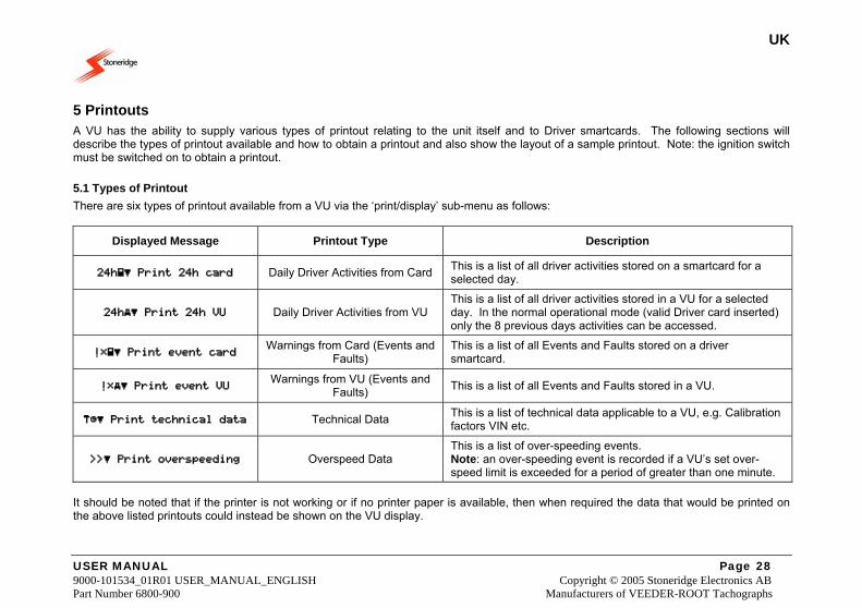
5.1 Types of Printout There are six types of printout available from a VU via the ‘print/display’ sub-menu as follows:
Displayed Message Printout Type Description
24h Print 24h card Daily Driver Activities from Card This is a list of all driver activities stored on a smartcard for a selected day.
24h Print 24h VU Daily Driver Activities from VU This is a list of all driver activities stored in a VU for a selected day. In the normal operational mode (valid Driver card inserted) only the 8 previous days activities can be accessed.
! Print event card Warnings from Card (Events and Faults)
This is a list of all Events and Faults stored on a driver smartcard.
! Print event VU Warnings from VU (Events and Faults) This is a list of all Events and Faults stored in a VU.
Print technical data Technical Data This is a list of technical data applicable to a VU, e.g. Calibration factors VIN etc.
Print overspeeding Overspeed Data This is a list of over-speeding events. Note: an over-speeding event is recorded if a VU’s set over-speed limit is exceeded for a period of greater than one minute.
It should be noted that if the printer is not working or if no printer paper is available, then when required the data that would be printed on the above listed printouts could instead be shown on the VU display.
UK
USER MANUAL Page 29 9000-101534_01R01 USER_MANUAL_ENGLISH Copyright © 2005 Stoneridge Electronics AB Part Number 6800-900 Manufacturers of VEEDER-ROOT Tachographs
5.2 How to Initiate a Printout and How to Stop a Printout Printouts are obtained via the “Print/Display” sub-menu and this can be accessed as follows. From any of the ‘Driving’ display screens (see Appendix 5 - Display Screens Selectable Whilst Driving for details), press the ‘enter’ button to access the ‘Main Menu’. Press the ‘up’ or ‘down’ buttons to scroll through the main menu functions until the “Print/Display Menu” screen is displayed as shown opposite. Press the ‘enter’ button again to enter the “Print/Display” sub-menu and use the ‘up’ or ‘down’ buttons to scroll through the list of six printout types (as described in the section 5.1 Types of Printout) until the required option is displayed on the bottom line. Press the ‘enter’ button once more to select the displayed ‘print/display’ option. If the wrong sub-menu is entered, press the ‘cancel’ button to go to the previous menu. Once a printout has been initiated, it can only be stopped by long-pressing the ‘cancel’ button. A warning message will be displayed as shown to indicate that printing has been cancelled. It should be noted that if there is a problem with the printer then a warning message will be displayed, with the exact message displayed dependant on the problem. A full list of printing instructions for each printout type and a description of printer warning messages is included in Appendix 4 - Details of Printing Routines.
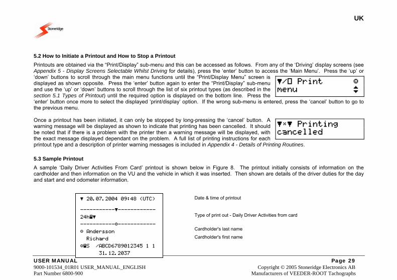
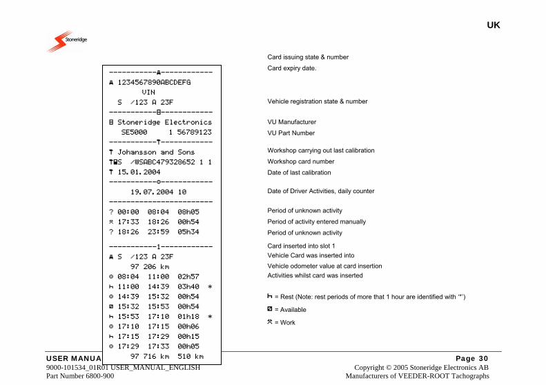
5.3 Sample Printout A sample ‘Daily Driver Activities From Card’ printout is shown below in Figure 8. The printout initially consists of information on the cardholder and then information on the VU and the vehicle in which it was inserted. Then shown are details of the driver duties for the day and start and end odometer information. Date & time of printout
Type of print out - Daily Driver Activities from card
Cardholder's last name
Cardholder's first name
/ Print menu
Printing cancelled
20.07.2004 09:48 (UTC)
-----------------------
24h
-----------------------
Andersson
Richard
S /ABCD6789012345 1 1
31.12.2037
UK
USER MANUAL Page 30 9000-101534_01R01 USER_MANUAL_ENGLISH Copyright © 2005 Stoneridge Electronics AB Part Number 6800-900 Manufacturers of VEEDER-ROOT Tachographs
Card issuing state & number
Card expiry date.
Vehicle registration state & number
VU Manufacturer
VU Part Number
Workshop carrying out last calibration
Workshop card number
Date of last calibration
Date of Driver Activities, daily counter
Period of unknown activity
Period of activity entered manually
Period of unknown activity
Card inserted into slot 1
Vehicle Card was inserted into
Vehicle odometer value at card insertion
Activities whilst card was inserted
= Rest (Note: rest periods of more that 1 hour are identified with ‘*’)
= Available
= Work
-----------------------
1234567890ABCDEFG
VIN
S /123 A 23F
-----------------------
Stoneridge Electronics
SE5000 1 56789123
-----------------------
Johansson and Sons
S /WSABC479328652 1 1
15.01.2004 -----------------------
19.07.2004 10
------------------------
? 00:00 08:04 08h05
17:33 18:26 00h54
? 18:26 23:59 05h34
-----------1------------
S /123 A 23F
97 206 km
08:04 11:00 02h57
11:00 14:39 03h40 *
14:39 15:32 00h54
15:32 15:53 00h54
15:53 17:10 01h18 *
17:10 17:15 00h06
17:15 17:29 00h15
17:29 17:33 00h05
97 716 km 510 km
UK
USER MANUAL Page 31 9000-101534_01R01 USER_MANUAL_ENGLISH Copyright © 2005 Stoneridge Electronics AB Part Number 6800-900 Manufacturers of VEEDER-ROOT Tachographs
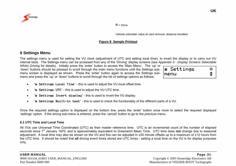
= Drive
Vehicle odometer value at card removal, distance travelled
Figure 8 Sample Printout
6 Settings Menu The settings menu is used for setting the VU clock (adjustment of UTC and setting local time), to invert the display or to carry out VU internal tests. The Settings menu can be accessed from any of the ‘Driving’ display screens (see Appendix 5 - Display Screens Selectable Whilst Driving for details). Initially press the ‘enter’ button to access the ‘Main Menu’. The ‘up’ or ‘down’ buttons should be pressed to scroll through the main menu functions until the Settings sub-menu screen is displayed as shown. Press the ‘enter’ button again to access the Settings sub-menu and press the ‘up’ or ‘down’ buttons to scroll through the list of settings options as follows:
• “ Settings Local Time“ - this is used to adjust the VU local offset time.
• “ Settings UTC” - this is used to adjust the VU UTC time.
• “ Settings Invert display” - this is used to invert the VU display.
• “ Settings Built-in test” - this is used to check the functionality of the different parts of a VU.
Once the required settings option is displayed on the bottom line, press the ‘enter’ button once more to select the required displayed ‘settings’ option. If the wrong sub-menu is entered, press the ‘cancel’ button to go to the previous menu.
6.1 UTC Time and Local Time All VUs use Universal Time Coordinated (UTC) as their master reference time. UTC is an incremental count of the number of elapsed seconds since 1st January 1970, and is approximately equivalent to Greenwich Mean Time. UTC time does not change due to seasonal adjustment. A local time may also be shown on the VU and this can be adjusted in ±30 minute offsets up to a maximum of ±12 hours from the UTC time. It should be noted that all driving event times stored are UTC times - setting a local time on the VU is for display purposes only.
Settings menu
UK
USER MANUAL Page 32 9000-101534_01R01 USER_MANUAL_ENGLISH Copyright © 2005 Stoneridge Electronics AB Part Number 6800-900 Manufacturers of VEEDER-ROOT Tachographs
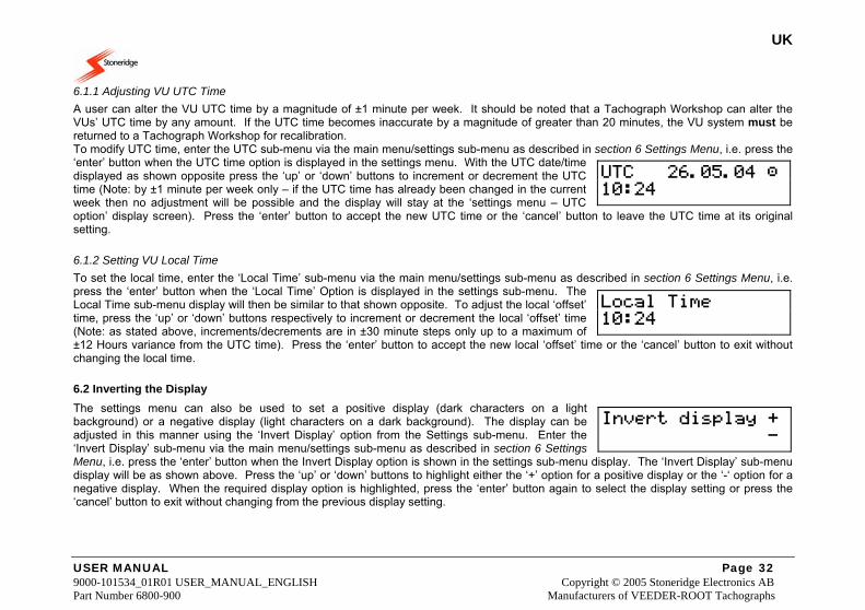
6.1.1 Adjusting VU UTC Time A user can alter the VU UTC time by a magnitude of ±1 minute per week. It should be noted that a Tachograph Workshop can alter the VUs’ UTC time by any amount. If the UTC time becomes inaccurate by a magnitude of greater than 20 minutes, the VU system must be returned to a Tachograph Workshop for recalibration. To modify UTC time, enter the UTC sub-menu via the main menu/settings sub-menu as described in section 6 Settings Menu, i.e. press the ‘enter’ button when the UTC time option is displayed in the settings menu. With the UTC date/time displayed as shown opposite press the ‘up’ or ‘down’ buttons to increment or decrement the UTC time (Note: by ±1 minute per week only – if the UTC time has already been changed in the current week then no adjustment will be possible and the display will stay at the ‘settings menu – UTC option’ display screen). Press the ‘enter’ button to accept the new UTC time or the ‘cancel’ button to leave the UTC time at its original setting.
6.1.2 Setting VU Local Time To set the local time, enter the ‘Local Time’ sub-menu via the main menu/settings sub-menu as described in section 6 Settings Menu, i.e. press the ‘enter’ button when the ‘Local Time’ Option is displayed in the settings sub-menu. The Local Time sub-menu display will then be similar to that shown opposite. To adjust the local ‘offset’ time, press the ‘up’ or ‘down’ buttons respectively to increment or decrement the local ‘offset’ time (Note: as stated above, increments/decrements are in ±30 minute steps only up to a maximum of ±12 Hours variance from the UTC time). Press the ‘enter’ button to accept the new local ‘offset’ time or the ‘cancel’ button to exit without changing the local time.
6.2 Inverting the Display The settings menu can also be used to set a positive display (dark characters on a light background) or a negative display (light characters on a dark background). The display can be adjusted in this manner using the ‘Invert Display’ option from the Settings sub-menu. Enter the ‘Invert Display’ sub-menu via the main menu/settings sub-menu as described in section 6 Settings Menu, i.e. press the ‘enter’ button when the Invert Display option is shown in the settings sub-menu display. The ‘Invert Display’ sub-menu display will be as shown above. Press the ‘up’ or ‘down’ buttons to highlight either the ‘+’ option for a positive display or the ‘-‘ option for a negative display. When the required display option is highlighted, press the ‘enter’ button again to select the display setting or press the ‘cancel’ button to exit without changing from the previous display setting.
UTC 26.05.04 10:24
Local Time 10:24
Invert display + -
UK
USER MANUAL Page 33 9000-101534_01R01 USER_MANUAL_ENGLISH Copyright © 2005 Stoneridge Electronics AB Part Number 6800-900 Manufacturers of VEEDER-ROOT Tachographs
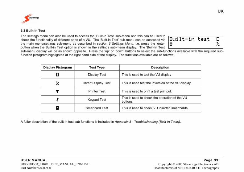
6.3 Built-In Test The settings menu can also be used to access the ‘Built-in Test’ sub-menu and this can be used to check the functionality of different parts of a VU. The ‘Built-in Test’ sub-menu can be accessed via the main menu/settings sub-menu as described in section 6 Settings Menu, i.e. press the ‘enter’ button when the Built-in Test option is shown in the settings sub-menu display. The ‘Built-In Test’ sub-menu display will be as shown opposite. Press the ‘up’ or ‘down’ buttons to select the sub-functions available with the required sub-function pictogram highlighted at the right hand side of the display. The functions available are as follows:
Display Pictogram Test Type Description
Display Test This is used to test the VU display
Invert Display Test This is used test the inversion of the VU display.
Printer Test This is used to print a test printout.
Keypad Test This is used to check the operation of the VU buttons.
Smartcard Test This is used to check VU inserted smartcards.
A fuller description of the built-in test sub-functions is included in Appendix 8 - Troubleshooting (Built-In Tests).
Built-in test
UK
USER MANUAL Page 34 9000-101534_01R01 USER_MANUAL_ENGLISH Copyright © 2005 Stoneridge Electronics AB Part Number 6800-900 Manufacturers of VEEDER-ROOT Tachographs
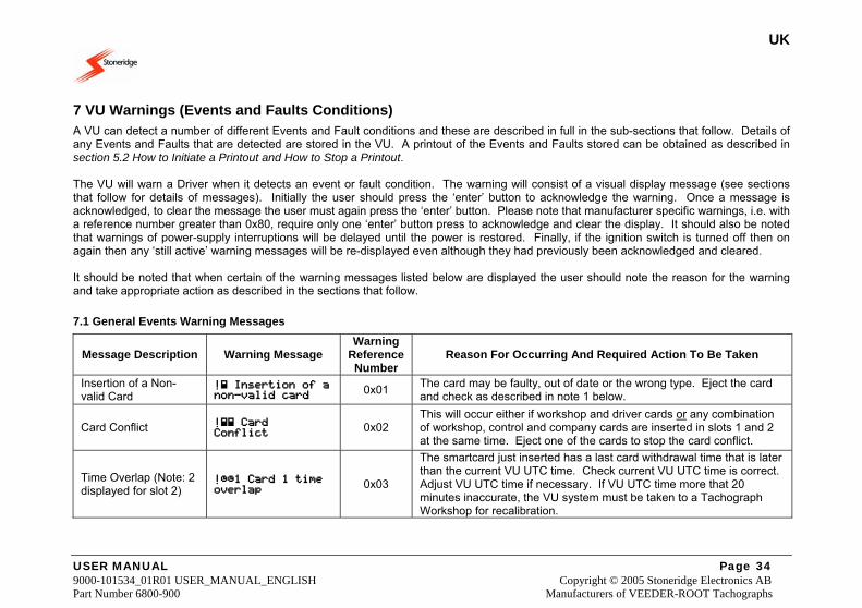
7 VU Warnings (Events and Faults Conditions) A VU can detect a number of different Events and Fault conditions and these are described in full in the sub-sections that follow. Details of any Events and Faults that are detected are stored in the VU. A printout of the Events and Faults stored can be obtained as described in section 5.2 How to Initiate a Printout and How to Stop a Printout. The VU will warn a Driver when it detects an event or fault condition. The warning will consist of a visual display message (see sections that follow for details of messages). Initially the user should press the ‘enter’ button to acknowledge the warning. Once a message is acknowledged, to clear the message the user must again press the ‘enter’ button. Please note that manufacturer specific warnings, i.e. with a reference number greater than 0x80, require only one ‘enter’ button press to acknowledge and clear the display. It should also be noted that warnings of power-supply interruptions will be delayed until the power is restored. Finally, if the ignition switch is turned off then on again then any ‘still active’ warning messages will be re-displayed even although they had previously been acknowledged and cleared. It should be noted that when certain of the warning messages listed below are displayed the user should note the reason for the warning and take appropriate action as described in the sections that follow.
7.1 General Events Warning Messages
Message Description Warning Message Warning
Reference Number
Reason For Occurring And Required Action To Be Taken
Insertion of a Non-valid Card
! Insertion of a non-valid card 0x01 The card may be faulty, out of date or the wrong type. Eject the card
and check as described in note 1 below.
Card Conflict ! Card Conflict 0x02
This will occur either if workshop and driver cards or any combination of workshop, control and company cards are inserted in slots 1 and 2 at the same time. Eject one of the cards to stop the card conflict.
Time Overlap (Note: 2 displayed for slot 2)
!1 Card 1 time overlap 0x03
The smartcard just inserted has a last card withdrawal time that is later than the current VU UTC time. Check current VU UTC time is correct. Adjust VU UTC time if necessary. If VU UTC time more that 20 minutes inaccurate, the VU system must be taken to a Tachograph Workshop for recalibration.
UK
USER MANUAL Page 35 9000-101534_01R01 USER_MANUAL_ENGLISH Copyright © 2005 Stoneridge Electronics AB Part Number 6800-900 Manufacturers of VEEDER-ROOT Tachographs
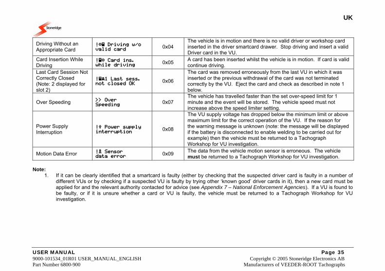
Driving Without an Appropriate Card
! Driving w/o valid card 0x04
The vehicle is in motion and there is no valid driver or workshop card inserted in the driver smartcard drawer. Stop driving and insert a valid Driver card in the VU.
Card Insertion While Driving
! Card ins. while driving 0x05 A card has been inserted whilst the vehicle is in motion. If card is valid
continue driving. Last Card Session Not Correctly Closed (Note: 2 displayed for slot 2)
!1 Last sess. not closed OK 0x06
The card was removed erroneously from the last VU in which it was inserted or the previous withdrawal of the card was not terminated correctly by the VU. Eject the card and check as described in note 1 below.
Over Speeding Over Speeding 0x07
The vehicle has travelled faster than the set over-speed limit for 1 minute and the event will be stored. The vehicle speed must not increase above the speed limiter setting.
Power Supply Interruption
! Power supply interruption 0x08
The VU supply voltage has dropped below the minimum limit or above maximum limit for the correct operation of the VU. If the reason for the warning message is unknown (note: the message will be displayed if the battery is disconnected to enable welding to be carried out for example) then the vehicle must be returned to a Tachograph Workshop for VU investigation.
Motion Data Error ! Sensor data error 0x09 The data from the vehicle motion sensor is erroneous. The vehicle
must be returned to a Tachograph Workshop for VU investigation. Note:
1. If it can be clearly identified that a smartcard is faulty (either by checking that the suspected driver card is faulty in a number of different VUs or by checking if a suspected VU is faulty by trying other ‘known good’ driver cards in it), then a new card must be applied for and the relevant authority contacted for advice (see Appendix 7 – National Enforcement Agencies). If a VU is found to be faulty, or if it is unsure whether a card or VU is faulty, the vehicle must be returned to a Tachograph Workshop for VU investigation.
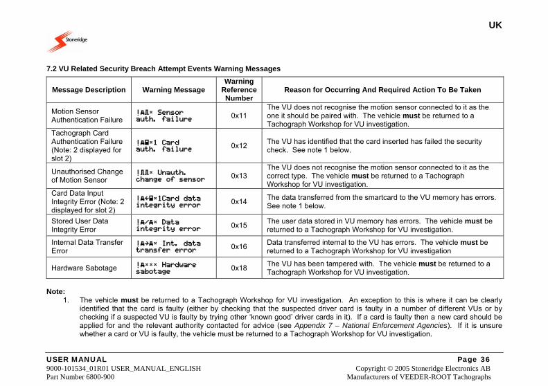
UK
USER MANUAL Page 36 9000-101534_01R01 USER_MANUAL_ENGLISH Copyright © 2005 Stoneridge Electronics AB Part Number 6800-900 Manufacturers of VEEDER-ROOT Tachographs
7.2 VU Related Security Breach Attempt Events Warning Messages
Message Description Warning Message Warning
Reference Number
Reason for Occurring And Required Action To Be Taken
Motion Sensor Authentication Failure
! Sensor auth. failure 0x11
The VU does not recognise the motion sensor connected to it as the one it should be paired with. The vehicle must be returned to a Tachograph Workshop for VU investigation.
Tachograph Card Authentication Failure (Note: 2 displayed for slot 2)
!1 Card auth. failure 0x12 The VU has identified that the card inserted has failed the security
check. See note 1 below.
Unauthorised Change of Motion Sensor
! Unauth. change of sensor 0x13
The VU does not recognise the motion sensor connected to it as the correct type. The vehicle must be returned to a Tachograph Workshop for VU investigation.
Card Data Input Integrity Error (Note: 2 displayed for slot 2)
!1Card data integrity error 0x14 The data transferred from the smartcard to the VU memory has errors.
See note 1 below.
Stored User Data Integrity Error
!/ Data integrity error 0x15 The user data stored in VU memory has errors. The vehicle must be
returned to a Tachograph Workshop for VU investigation.
Internal Data Transfer Error
! Int. data transfer error 0x16 Data transferred internal to the VU has errors. The vehicle must be
returned to a Tachograph Workshop for VU investigation
Hardware Sabotage ! Hardware sabotage 0x18 The VU has been tampered with. The vehicle must be returned to a
Tachograph Workshop for VU investigation. Note:
1. The vehicle must be returned to a Tachograph Workshop for VU investigation. An exception to this is where it can be clearly identified that the card is faulty (either by checking that the suspected driver card is faulty in a number of different VUs or by checking if a suspected VU is faulty by trying other ‘known good’ driver cards in it). If a card is faulty then a new card should be applied for and the relevant authority contacted for advice (see Appendix 7 – National Enforcement Agencies). If it is unsure whether a card or VU is faulty, the vehicle must be returned to a Tachograph Workshop for VU investigation.
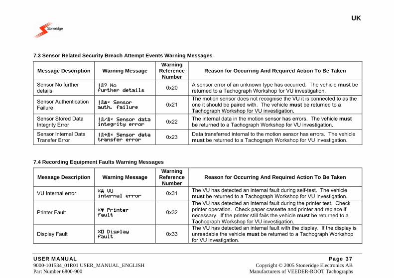
UK
USER MANUAL Page 37 9000-101534_01R01 USER_MANUAL_ENGLISH Copyright © 2005 Stoneridge Electronics AB Part Number 6800-900 Manufacturers of VEEDER-ROOT Tachographs
7.3 Sensor Related Security Breach Attempt Events Warning Messages
Message Description Warning Message Warning
Reference Number
Reason for Occurring And Required Action To Be Taken
Sensor No further details
!? No further details
0x20 A sensor error of an unknown type has occurred. The vehicle must be returned to a Tachograph Workshop for VU investigation.
Sensor Authentication Failure
! Sensor auth. failure 0x21
The motion sensor does not recognise the VU it is connected to as the one it should be paired with. The vehicle must be returned to a Tachograph Workshop for VU investigation.
Sensor Stored Data Integrity Error
!/ Sensor data integrity error 0x22 The internal data in the motion sensor has errors. The vehicle must
be returned to a Tachograph Workshop for VU investigation.
Sensor Internal Data Transfer Error
! Sensor data transfer error 0x23 Data transferred internal to the motion sensor has errors. The vehicle
must be returned to a Tachograph Workshop for VU investigation.
7.4 Recording Equipment Faults Warning Messages
Message Description Warning Message Warning
Reference Number
Reason for Occurring And Required Action To Be Taken
VU Internal error VU internal error 0x31 The VU has detected an internal fault during self-test. The vehicle
must be returned to a Tachograph Workshop for VU investigation.
Printer Fault Printer fault 0x32
The VU has detected an internal fault during the printer test. Check printer operation. Check paper cassette and printer and replace if necessary. If the printer still fails the vehicle must be returned to a Tachograph Workshop for VU investigation.
Display Fault Display fault 0x33
The VU has detected an internal fault with the display. If the display is unreadable the vehicle must be returned to a Tachograph Workshop for VU investigation.
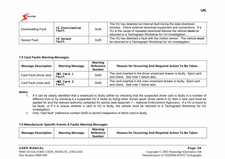
UK
USER MANUAL Page 38 9000-101534_01R01 USER_MANUAL_ENGLISH Copyright © 2005 Stoneridge Electronics AB Part Number 6800-900 Manufacturers of VEEDER-ROOT Tachographs
Downloading Fault Downloading fault 0x34
The VU has detected an internal fault during the data download process. Check external download equipment and connections. If a VU is the cause of repeated download failures the vehicle must be returned to a Tachograph Workshop for VU investigation.
Sensor Fault Sensor fault 0x35 The VU has detected a fault with the motion sensor. The vehicle must
be returned to a Tachograph Workshop for VU investigation.
7.5 Card Faults Warning Messages
Message Description Warning Message Warning
Reference Number
Reason for Occurring And Required Action To Be Taken
Card Fault (driver slot) 1 Card 1 Fault 0x40 The card inserted in the driver smartcard drawer is faulty. Eject card
and check. See note 1 below also.
Card Fault (crew slot) 2 Card 2 fault 0x40 The card inserted in the crew smartcard drawer is faulty. Eject card
and check. See note 1 below also. Notes:
1. If it can be clearly identified that a smartcard is faulty (either by checking that the suspected driver card is faulty in a number of different VUs or by checking if a suspected VU is faulty by trying other ‘known good’ driver cards in it), then a new card must be applied for and the relevant authority contacted for advice (see Appendix 7 – National Enforcement Agencies). If a VU is found to be faulty, or if it is unsure whether a card or VU is faulty, the vehicle must be returned to a Tachograph Workshop for VU investigation.
2. Only “card fault” (reference number 0x40) is stored irrespective of which card is faulty.
7.6 Manufacturer Specific Events & Faults Warning Messages
Message Description Warning Message Warning
Reference Number
Reason for Occurring And Required Action To Be Taken
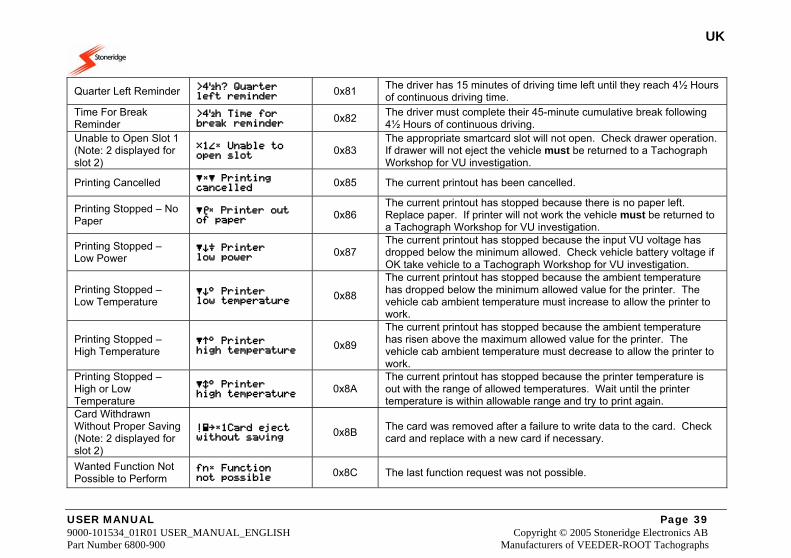
UK
USER MANUAL Page 39 9000-101534_01R01 USER_MANUAL_ENGLISH Copyright © 2005 Stoneridge Electronics AB Part Number 6800-900 Manufacturers of VEEDER-ROOT Tachographs
Quarter Left Reminder >4h? Quarter left reminder 0x81 The driver has 15 minutes of driving time left until they reach 4½ Hours
of continuous driving time. Time For Break Reminder
>4h Time for break reminder 0x82 The driver must complete their 45-minute cumulative break following
4½ Hours of continuous driving. Unable to Open Slot 1 (Note: 2 displayed for slot 2)
1 Unable to open slot
0x83 The appropriate smartcard slot will not open. Check drawer operation. If drawer will not eject the vehicle must be returned to a Tachograph Workshop for VU investigation.
Printing Cancelled Printing cancelled
0x85 The current printout has been cancelled.
Printing Stopped – No Paper
Printer out of paper
0x86 The current printout has stopped because there is no paper left. Replace paper. If printer will not work the vehicle must be returned to a Tachograph Workshop for VU investigation.
Printing Stopped – Low Power
Printer low power
0x87 The current printout has stopped because the input VU voltage has dropped below the minimum allowed. Check vehicle battery voltage if OK take vehicle to a Tachograph Workshop for VU investigation.
Printing Stopped – Low Temperature
Printer low temperature
0x88
The current printout has stopped because the ambient temperature has dropped below the minimum allowed value for the printer. The vehicle cab ambient temperature must increase to allow the printer to work.
Printing Stopped – High Temperature
Printer high temperature
0x89
The current printout has stopped because the ambient temperature has risen above the maximum allowed value for the printer. The vehicle cab ambient temperature must decrease to allow the printer to work.
Printing Stopped – High or Low Temperature
Printer high temperature
0x8A The current printout has stopped because the printer temperature is out with the range of allowed temperatures. Wait until the printer temperature is within allowable range and try to print again.
Card Withdrawn Without Proper Saving (Note: 2 displayed for slot 2)
!1Card eject without saving
0x8B The card was removed after a failure to write data to the card. Check card and replace with a new card if necessary.
Wanted Function Not Possible to Perform
fn Function not possible
0x8C The last function request was not possible.
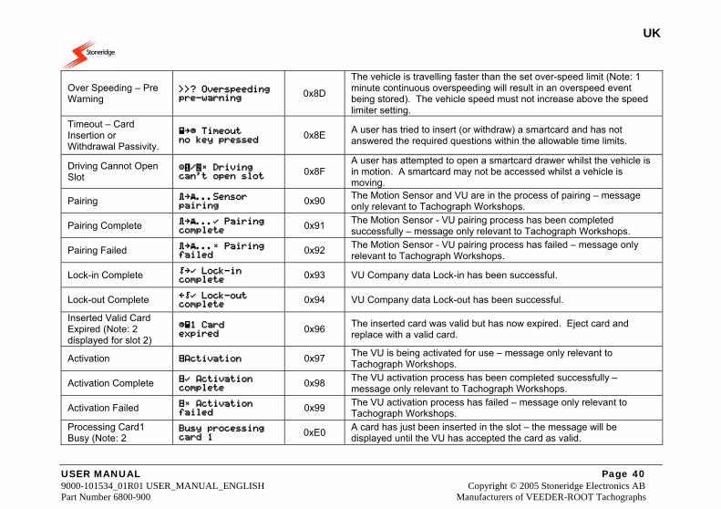
UK
USER MANUAL Page 40 9000-101534_01R01 USER_MANUAL_ENGLISH Copyright © 2005 Stoneridge Electronics AB Part Number 6800-900 Manufacturers of VEEDER-ROOT Tachographs
Over Speeding – Pre Warning
? Overspeeding pre-warning
0x8D
The vehicle is travelling faster than the set over-speed limit (Note: 1 minute continuous overspeeding will result in an overspeed event being stored). The vehicle speed must not increase above the speed limiter setting.
Timeout – Card Insertion or Withdrawal Passivity.
Timeout no key pressed
0x8E A user has tried to insert (or withdraw) a smartcard and has not answered the required questions within the allowable time limits.
Driving Cannot Open Slot
/ Driving can't open slot
0x8F A user has attempted to open a smartcard drawer whilst the vehicle is in motion. A smartcard may not be accessed whilst a vehicle is moving.
Pairing ...Sensor pairing
0x90 The Motion Sensor and VU are in the process of pairing – message only relevant to Tachograph Workshops.
Pairing Complete ... Pairing complete
0x91 The Motion Sensor - VU pairing process has been completed successfully – message only relevant to Tachograph Workshops.
Pairing Failed ... Pairing failed
0x92 The Motion Sensor - VU pairing process has failed – message only relevant to Tachograph Workshops.
Lock-in Complete Lock-in complete
0x93 VU Company data Lock-in has been successful.
Lock-out Complete Lock-out complete
0x94 VU Company data Lock-out has been successful.
Inserted Valid Card Expired (Note: 2 displayed for slot 2)
1 Card expired
0x96 The inserted card was valid but has now expired. Eject card and replace with a valid card.
Activation Activation 0x97 The VU is being activated for use – message only relevant to Tachograph Workshops.
Activation Complete Activation complete
0x98 The VU activation process has been completed successfully – message only relevant to Tachograph Workshops.
Activation Failed Activation failed
0x99 The VU activation process has failed – message only relevant to Tachograph Workshops.
Processing Card1 Busy (Note: 2
Busy processing card 1
0xE0 A card has just been inserted in the slot – the message will be displayed until the VU has accepted the card as valid.
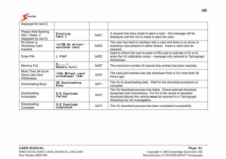
UK
USER MANUAL Page 41 9000-101534_01R01 USER_MANUAL_ENGLISH Copyright © 2005 Stoneridge Electronics AB Part Number 6800-900 Manufacturers of VEEDER-ROOT Tachographs
displayed for slot 2)
Please Wait Ejecting Slot 1 (Note: 2 displayed for slot 2)
Ejecting Card 1
0xEC A request has been made to eject a card – the message will be displayed until the VU is ready to eject the card.
No Driver or Workshop Card Inserted
!/ No driver/ workshop card
0xED The user has tried to interface with a card and there is no driver or workshop card present in either drawer. Insert a valid card as required.
Enter PIN 1 PIN? 0xEE Used to inform the user to enter a PIN code to activate a VU or to enter the VU calibration mode – message only relevant to Tachograph Workshops.
Memory Full M.....! Memory full!
0xEF The maximum number of manual duty entries has been reached.
More Than 24 hours Since Last Card Withdrawal.
>24h last card withdrawal >24h
0xF0 The card just inserted was last withdrawn from a VU more than 24 Hours ago.
Downloading Busy Downloading busy
0xF1 The VU is downloading data. Wait for the download procedure to complete.
Downloading Incomplete
Download failed
0xF2
The VU download process has failed. Check external download equipment and connections. If a VU is the cause of repeated download failures the vehicle must be returned to a Tachograph Workshop for VU investigation.
Downloading Complete
Download completed
0xF3 The VU download process has been completed successfully.
UK
USER MANUAL Page 42 9000-101534_01R01 USER_MANUAL_ENGLISH Copyright © 2005 Stoneridge Electronics AB Part Number 6800-900 Manufacturers of VEEDER-ROOT Tachographs
8 Care and Maintenance of a VU
8.1 Cleanliness Ensure that the Smartcard drawers are closed and latched at all times – except when inserting or removing cards. Also ensure that the paper cassette is closed at all times except when changing the printer paper. These will prevent the ingress of contaminants, which could lead to premature failure of the VU. If it is necessary to clean the outside of the VU use a mild detergent solution. Avoid the use of solvents that could permanently damage the plastic fascia.
8.2 Protecting the VU System from Damage • Disconnect the VU from its electrical supply if electrical welding is carried out on a vehicle or if prolonged boost starting of the
vehicle is anticipated or if high-level transient voltages are anticipated. Note: Failure of other electrical components on a vehicle, for example the alternator regulator, could damage the VU, as it is permanently connected to the battery.
• The Smartcard drawers are not designed to support weight when in the open position. • When removing the paper cassette do not use excessive force as this may cause permanent damage. The correct method for
removing the paper cassette is fully described in section 3.6 Paper Cassette. • Replacement printer paper must be a Stoneridge approved type – failure to use approved printer paper may cause permanent
damage to the printer mechanism. • Smartcards must be handled with care – do not flex or bend the cards. Ensure that the card contacts are kept free from dirt – clean
with a soft damp cloth if necessary.
8.3 Printer Maintenance The only user serviceable parts in the Stoneridge VU are the paper cassette and the printer paper. Do not attempt to service any other VU parts. If the paper cassette is damaged then the complete cassette must be replaced as a single item – see section 3.6 Paper Cassette for information on how to replace the paper cassette and Appendix 6 - Printer Spare Parts for how to obtain spare parts.
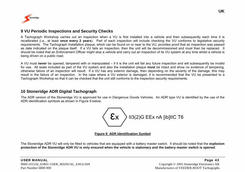
UK
USER MANUAL Page 43 9000-101534_01R01 USER_MANUAL_ENGLISH Copyright © 2005 Stoneridge Electronics AB Part Number 6800-900 Manufacturers of VEEDER-ROOT Tachographs
9 VU Periodic Inspections and Security Checks A Tachograph Workshop carries out an inspection when a VU is first installed into a vehicle and then subsequently each time it is recalibrated (i.e., at least once every 2 years). Part of each inspection will include checking the VU conforms to legislative security requirements. The Tachograph Installation plaque, which can be found on or near to the VU, provides proof that an inspection was passed as date indicated on the plaque itself. If a VU fails an inspection, then the unit will be decommissioned and must then be replaced. It should be noted that an Enforcement Officer might stop a vehicle and carry out an inspection of its VU system at any time whilst a vehicle is being driven on a public road. A VU must never be opened, tampered with or manipulated – if it is the unit will fail any future inspection and will subsequently be invalid for use. All seals included as part of the VU system and also the installation plaque must be intact and show no evidence of tampering, otherwise failure of an inspection will result. If a VU has any exterior damage, then depending on the severity of the damage, this may result in the failure of an inspection. In the case where a VU exterior is damaged, it is recommended that the VU be presented to a Tachograph Workshop so that it can be checked that the unit still conforms to the inspection security requirements.
10 Stoneridge ADR Digital Tachograph The ADR version of the Stoneridge VU is approved for use in Dangerous Goods Vehicles. An ADR type VU is identified by the use of the ADR identification symbols as shown in Figure 9 below. II3(2)G EEx nA [ib]IIC T6
Figure 9 ADR Identification Symbol
The Stoneridge ADR VU will only be fitted to vehicles that are equipped with a battery master switch. It should be noted that the explosion protection of the Stoneridge ADR VU is only ensured when the vehicle is stationary and the battery master switch is opened.
εx
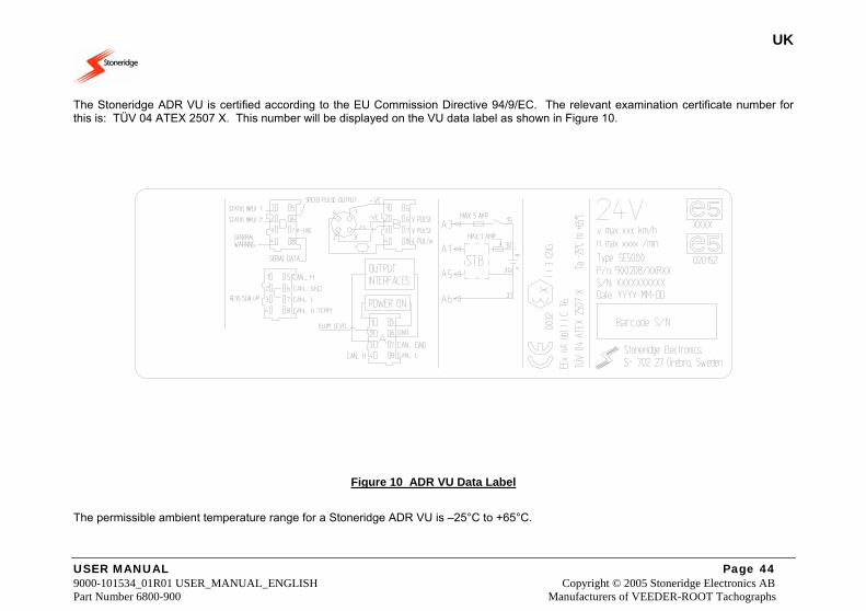
UK
USER MANUAL Page 44 9000-101534_01R01 USER_MANUAL_ENGLISH Copyright © 2005 Stoneridge Electronics AB Part Number 6800-900 Manufacturers of VEEDER-ROOT Tachographs
The Stoneridge ADR VU is certified according to the EU Commission Directive 94/9/EC. The relevant examination certificate number for this is: TÜV 04 ATEX 2507 X. This number will be displayed on the VU data label as shown in Figure 10.
Figure 10 ADR VU Data Label
The permissible ambient temperature range for a Stoneridge ADR VU is –25°C to +65°C.
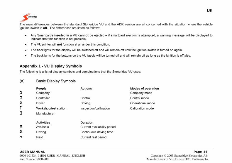
UK
USER MANUAL Page 45 9000-101534_01R01 USER_MANUAL_ENGLISH Copyright © 2005 Stoneridge Electronics AB Part Number 6800-900 Manufacturers of VEEDER-ROOT Tachographs
The main differences between the standard Stoneridge VU and the ADR version are all concerned with the situation where the vehicle ignition switch is off. The differences are listed as follows:
• Any Smartcards inserted in a VU cannot be ejected – if smartcard ejection is attempted, a warning message will be displayed to indicate that this function is not possible.
• The VU printer will not function at all under this condition.
• The backlights for the display will be switched off and will remain off until the ignition switch is turned on again.
• The backlights for the buttons on the VU fascia will be turned off and will remain off as long as the ignition is off also.
Appendix 1 - VU Display Symbols The following is a list of display symbols and combinations that the Stoneridge VU uses: (a) Basic Display Symbols People Actions Modes of operation Company Company mode Controller Control Control mode Driver Driving Operational mode Workshop/test station Inspection/calibration Calibration mode Manufacturer Activities Duration Available Current availability period Driving Continuous driving time Rest Current rest period
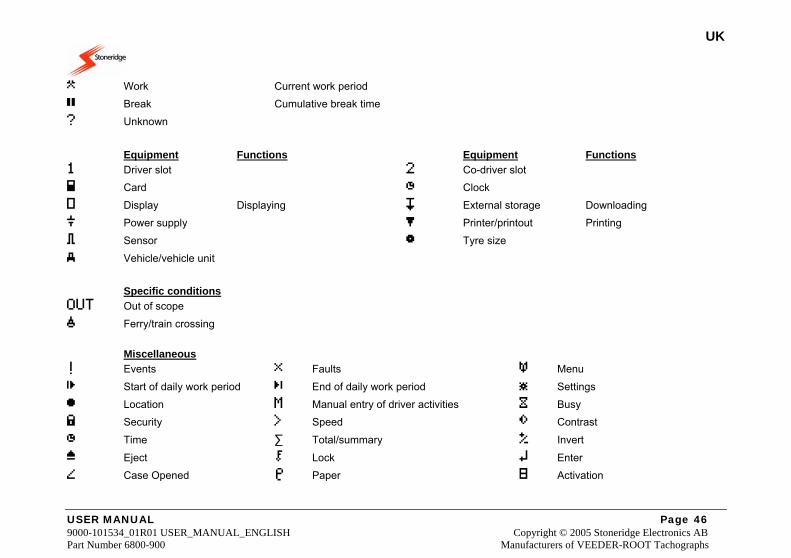
UK
USER MANUAL Page 46 9000-101534_01R01 USER_MANUAL_ENGLISH Copyright © 2005 Stoneridge Electronics AB Part Number 6800-900 Manufacturers of VEEDER-ROOT Tachographs
Work Current work period Break Cumulative break time ? Unknown
Equipment Functions Equipment Functions 1 Driver slot 2 Co-driver slot Card Clock Display Displaying External storage Downloading Power supply Printer/printout Printing Sensor Tyre size Vehicle/vehicle unit Specific conditions OUT Out of scope Ferry/train crossing Miscellaneous ! Events Faults Menu Start of daily work period End of daily work period Settings Location M Manual entry of driver activities Busy Security Speed Contrast
Time ∑ Total/summary Invert
Eject Lock Enter Case Opened Paper Activation
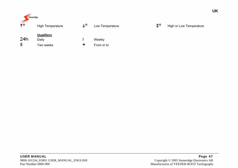
UK
USER MANUAL Page 47 9000-101534_01R01 USER_MANUAL_ENGLISH Copyright © 2005 Stoneridge Electronics AB Part Number 6800-900 Manufacturers of VEEDER-ROOT Tachographs
High Temperature Low Temperature High or Low Temperature Qualifiers 24h Daily I Weekly Two weeks From or to

UK
USER MANUAL Page 48 9000-101534_01R01 USER_MANUAL_ENGLISH Copyright © 2005 Stoneridge Electronics AB Part Number 6800-900 Manufacturers of VEEDER-ROOT Tachographs
(b) Display Symbol Combinations Miscellaneous Control place From vehicle Location start of daily work period Location end of daily work period From time To time OUT Out of scope begin OUT Out of scope end Cards Driver card Company card Control card Workshop card --- No card Driving I Driving time for one week Driving time for two weeks
Printouts 24h Driver activities from card daily printout 24h Driver activities from VU daily printout ! Events and faults from card printout ! Events and faults from VU printout Technical data printout Over speeding printout Manual Entries ? Still same daily work period? ? End of previous work period? ? Enter location of start of work period ? Confirm or enter location of end of work period.
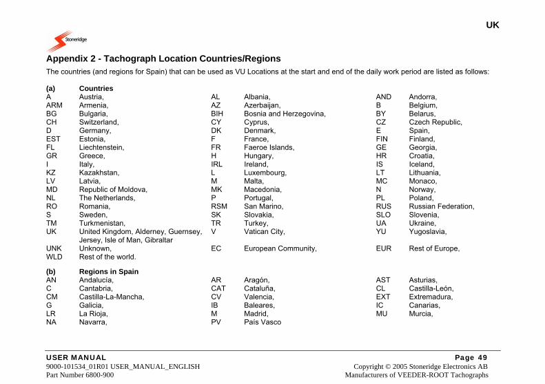
UK
USER MANUAL Page 49 9000-101534_01R01 USER_MANUAL_ENGLISH Copyright © 2005 Stoneridge Electronics AB Part Number 6800-900 Manufacturers of VEEDER-ROOT Tachographs
Appendix 2 - Tachograph Location Countries/Regions The countries (and regions for Spain) that can be used as VU Locations at the start and end of the daily work period are listed as follows: (a) Countries A Austria, AL Albania, AND Andorra, ARM Armenia, AZ Azerbaijan, B Belgium, BG Bulgaria, BIH Bosnia and Herzegovina, BY Belarus, CH Switzerland, CY Cyprus, CZ Czech Republic, D Germany, DK Denmark, E Spain, EST Estonia, F France, FIN Finland, FL Liechtenstein, FR Faeroe Islands, GE Georgia, GR Greece, H Hungary, HR Croatia, I Italy, IRL Ireland, IS Iceland, KZ Kazakhstan, L Luxembourg, LT Lithuania, LV Latvia, M Malta, MC Monaco, MD Republic of Moldova, MK Macedonia, N Norway, NL The Netherlands, P Portugal, PL Poland, RO Romania, RSM San Marino, RUS Russian Federation, S Sweden, SK Slovakia, SLO Slovenia, TM Turkmenistan, TR Turkey, UA Ukraine, UK United Kingdom, Alderney, Guernsey, V Vatican City, YU Yugoslavia,
Jersey, Isle of Man, Gibraltar UNK Unknown, EC European Community, EUR Rest of Europe, WLD Rest of the world. (b) Regions in Spain AN Andalucía, AR Aragón, AST Asturias, C Cantabria, CAT Cataluña, CL Castilla-León, CM Castilla-La-Mancha, CV Valencia, EXT Extremadura, G Galicia, IB Baleares, IC Canarias, LR La Rioja, M Madrid, MU Murcia, NA Navarra, PV País Vasco
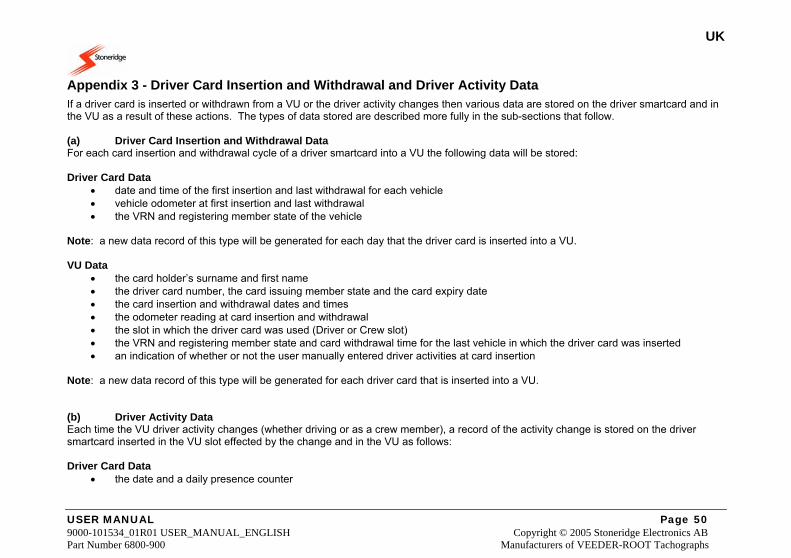
UK
USER MANUAL Page 50 9000-101534_01R01 USER_MANUAL_ENGLISH Copyright © 2005 Stoneridge Electronics AB Part Number 6800-900 Manufacturers of VEEDER-ROOT Tachographs
Appendix 3 - Driver Card Insertion and Withdrawal and Driver Activity Data If a driver card is inserted or withdrawn from a VU or the driver activity changes then various data are stored on the driver smartcard and in the VU as a result of these actions. The types of data stored are described more fully in the sub-sections that follow. (a) Driver Card Insertion and Withdrawal Data For each card insertion and withdrawal cycle of a driver smartcard into a VU the following data will be stored: Driver Card Data
• date and time of the first insertion and last withdrawal for each vehicle • vehicle odometer at first insertion and last withdrawal • the VRN and registering member state of the vehicle
Note: a new data record of this type will be generated for each day that the driver card is inserted into a VU. VU Data
• the card holder’s surname and first name • the driver card number, the card issuing member state and the card expiry date • the card insertion and withdrawal dates and times • the odometer reading at card insertion and withdrawal • the slot in which the driver card was used (Driver or Crew slot) • the VRN and registering member state and card withdrawal time for the last vehicle in which the driver card was inserted • an indication of whether or not the user manually entered driver activities at card insertion
Note: a new data record of this type will be generated for each driver card that is inserted into a VU. (b) Driver Activity Data Each time the VU driver activity changes (whether driving or as a crew member), a record of the activity change is stored on the driver smartcard inserted in the VU slot effected by the change and in the VU as follows: Driver Card Data
• the date and a daily presence counter
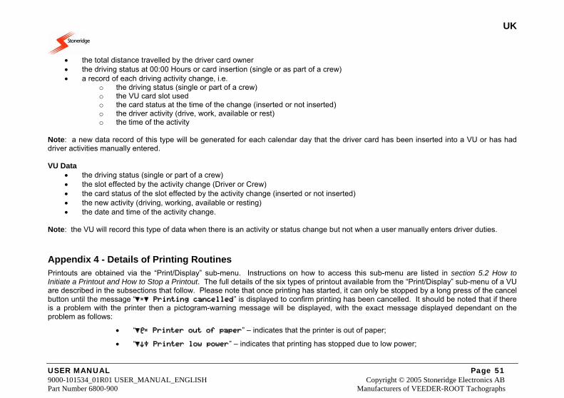
UK
USER MANUAL Page 51 9000-101534_01R01 USER_MANUAL_ENGLISH Copyright © 2005 Stoneridge Electronics AB Part Number 6800-900 Manufacturers of VEEDER-ROOT Tachographs
• the total distance travelled by the driver card owner • the driving status at 00:00 Hours or card insertion (single or as part of a crew) • a record of each driving activity change, i.e.
o the driving status (single or part of a crew) o the VU card slot used o the card status at the time of the change (inserted or not inserted) o the driver activity (drive, work, available or rest) o the time of the activity
Note: a new data record of this type will be generated for each calendar day that the driver card has been inserted into a VU or has had driver activities manually entered. VU Data
• the driving status (single or part of a crew) • the slot effected by the activity change (Driver or Crew) • the card status of the slot effected by the activity change (inserted or not inserted) • the new activity (driving, working, available or resting) • the date and time of the activity change.
Note: the VU will record this type of data when there is an activity or status change but not when a user manually enters driver duties.
Appendix 4 - Details of Printing Routines Printouts are obtained via the “Print/Display” sub-menu. Instructions on how to access this sub-menu are listed in section 5.2 How to Initiate a Printout and How to Stop a Printout. The full details of the six types of printout available from the “Print/Display” sub-menu of a VU are described in the subsections that follow. Please note that once printing has started, it can only be stopped by a long press of the cancel button until the message “ Printing cancelled” is displayed to confirm printing has been cancelled. It should be noted that if there is a problem with the printer then a pictogram-warning message will be displayed, with the exact message displayed dependant on the problem as follows:
• “ Printer out of paper” – indicates that the printer is out of paper;
• “ Printer low power” – indicates that printing has stopped due to low power;
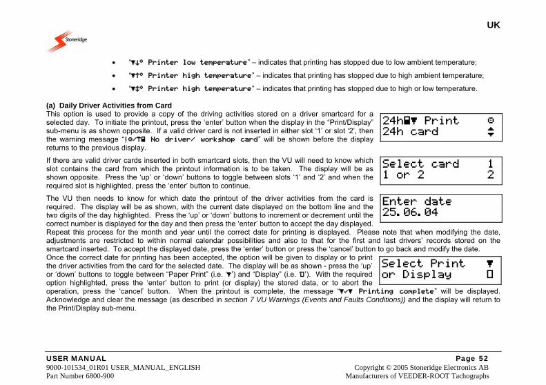
UK
USER MANUAL Page 52 9000-101534_01R01 USER_MANUAL_ENGLISH Copyright © 2005 Stoneridge Electronics AB Part Number 6800-900 Manufacturers of VEEDER-ROOT Tachographs
• “ Printer low temperature” – indicates that printing has stopped due to low ambient temperature;
• “ Printer high temperature” – indicates that printing has stopped due to high ambient temperature;
• “ Printer high temperature” – indicates that printing has stopped due to high or low temperature. (a) Daily Driver Activities from Card This option is used to provide a copy of the driving activities stored on a driver smartcard for a selected day. To initiate the printout, press the ‘enter’ button when the display in the “Print/Display” sub-menu is as shown opposite. If a valid driver card is not inserted in either slot ‘1’ or slot ‘2’, then the warning message “!/ No driver/ workshop card” will be shown before the display returns to the previous display.
If there are valid driver cards inserted in both smartcard slots, then the VU will need to know which slot contains the card from which the printout information is to be taken. The display will be as shown opposite. Press the ‘up’ or ‘down’ buttons to toggle between slots ‘1’ and ‘2’ and when the required slot is highlighted, press the ‘enter’ button to continue.
The VU then needs to know for which date the printout of the driver activities from the card is required. The display will be as shown, with the current date displayed on the bottom line and the two digits of the day highlighted. Press the ‘up’ or ‘down’ buttons to increment or decrement until the correct number is displayed for the day and then press the ‘enter’ button to accept the day displayed. Repeat this process for the month and year until the correct date for printing is displayed. Please note that when modifying the date, adjustments are restricted to within normal calendar possibilities and also to that for the first and last drivers’ records stored on the smartcard inserted. To accept the displayed date, press the ‘enter’ button or press the ‘cancel’ button to go back and modify the date. Once the correct date for printing has been accepted, the option will be given to display or to print the driver activities from the card for the selected date. The display will be as shown - press the ‘up’ or ‘down’ buttons to toggle between “Paper Print” (i.e. ‘’) and “Display” (i.e. ‘’). With the required option highlighted, press the ‘enter’ button to print (or display) the stored data, or to abort the operation, press the ‘cancel’ button. When the printout is complete, the message “ Printing complete” will be displayed. Acknowledge and clear the message (as described in section 7 VU Warnings (Events and Faults Conditions)) and the display will return to the Print/Display sub-menu.
24h Print 24h card
Select card 1 1 or 2 2
Enter date 25.06.04
Select Print or Display
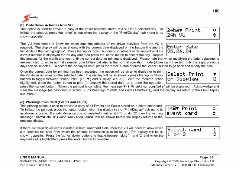
UK
USER MANUAL Page 53 9000-101534_01R01 USER_MANUAL_ENGLISH Copyright © 2005 Stoneridge Electronics AB Part Number 6800-900 Manufacturers of VEEDER-ROOT Tachographs
(b) Daily Driver Activities from VU This option is used to provide a copy of the driver activities stored in a VU for a selected day. To initiate the printout, press the ‘enter’ button when the display in the “Print/Display” sub-menu is as shown opposite. The VU then needs to know for which date the printout of the driver activities from the VU is required. The display will be as shown, with the current date displayed on the bottom line and the two digits of the day highlighted. Press the ‘up’ or ‘down’ buttons to increment or decrement until the correct number is displayed for the day and then press the ‘enter’ button to accept the day. Repeat this process for the month and year until the correct date for printing is displayed. Please note that when modifying the date, adjustments are restricted to within normal calendar possibilities but also in the normal operation mode (driver card inserted) only the eight previous days can be selected. To accept the displayed date, press the ‘enter’ button or press the ‘cancel’ button to go back and modify the date.
Once the correct date for printing has been accepted, the option will be given to display or to print the VU driver activities for the selected date. The display will be as shown - press the ‘up’ or ‘down’ buttons to toggle between “Paper Print” (i.e. ‘’) and “Display” (i.e. ‘’). With the required option highlighted, press the ‘enter’ button to print (or display) the stored data, or to abort the operation, press the ‘cancel’ button. When the printout is complete, the message “ Printing complete” will be displayed. Acknowledge and clear the message (as described in section 7 VU Warnings (Events and Faults Conditions)) and the display will return to the Print/Display sub-menu. (c) Warnings from Card (Events and Faults) This printing option is used to provide a copy of all Events and Faults stored on a driver smartcard. To initiate the printout, press the ‘enter’ button when the display in the “Print/Display” sub-menu is as shown opposite. If a valid driver card is not inserted in either slot ‘1’ or slot ‘2’, then the warning message “!/ No driver/ workshop card” will be shown before the display returns to the previous display. If there are valid driver cards inserted in both smartcard slots, then the VU will need to know which slot contains the card from which the printout information is to be taken. The display will be as shown opposite. Press the ‘up’ or ‘down’ buttons to toggle between slots ‘1’ and ‘2’ and when the required slot is highlighted, press the ‘enter’ button to continue.
24h Print 24h VU
Enter date 25.06.04
Select Print or Display
! Print event card
Select card 1 1 or 2 2
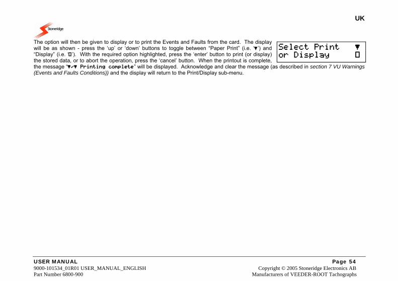
UK
USER MANUAL Page 54 9000-101534_01R01 USER_MANUAL_ENGLISH Copyright © 2005 Stoneridge Electronics AB Part Number 6800-900 Manufacturers of VEEDER-ROOT Tachographs
The option will then be given to display or to print the Events and Faults from the card. The display will be as shown - press the ‘up’ or ‘down’ buttons to toggle between “Paper Print” (i.e. ‘’) and “Display” (i.e. ‘’). With the required option highlighted, press the ‘enter’ button to print (or display) the stored data, or to abort the operation, press the ‘cancel’ button. When the printout is complete, the message “ Printing complete” will be displayed. Acknowledge and clear the message (as described in section 7 VU Warnings (Events and Faults Conditions)) and the display will return to the Print/Display sub-menu.
Select Print or Display
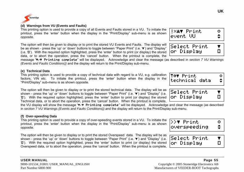
UK
USER MANUAL Page 55 9000-101534_01R01 USER_MANUAL_ENGLISH Copyright © 2005 Stoneridge Electronics AB Part Number 6800-900 Manufacturers of VEEDER-ROOT Tachographs
(d) Warnings from VU (Events and Faults) This printing option is used to provide a copy of all Events and Faults stored in a VU. To initiate the printout, press the ‘enter’ button when the display in the “Print/Display” sub-menu is as shown opposite. The option will then be given to display or to print the stored VU Events and Faults. The display will be as shown - press the ‘up’ or ‘down’ buttons to toggle between “Paper Print” (i.e. ‘’) and “Display” (i.e. ‘’). With the required option highlighted, press the ‘enter’ button to print (or display) the stored data, or to abort the operation, press the ‘cancel’ button. When the printout is complete, the message “ Printing complete” will be displayed. Acknowledge and clear the message (as described in section 7 VU Warnings (Events and Faults Conditions)) and the display will return to the Print/Display sub-menu. (e) Technical Data This printing option is used to provide a copy of technical data with regard to a VU, e.g. calibration factors, VIN etc. To initiate the printout, press the ‘enter’ button when the display in the “Print/Display” sub-menu is as shown opposite. The option will then be given to display or to print the stored technical data. The display will be as shown - press the ‘up’ or ‘down’ buttons to toggle between “Paper Print” (i.e. ‘’) and “Display” (i.e. ‘’). With the required option highlighted, press the ‘enter’ button to print (or display) the stored Technical data, or to abort the operation, press the ‘cancel’ button. When the printout is complete, the VU display will show the message “ Printing complete” will be displayed. Acknowledge and clear the message (as described in section 7 VU Warnings (Events and Faults Conditions)) and the display will return to the Print/Display sub-menu. (f) Over-speeding Data This printing option is used to provide a copy of over-speeding events stored in a VU. To initiate the printout, press the ‘enter’ button when the display in the “Print/Display” sub-menu is as shown opposite. The option will then be given to display or to print the stored Overspeed data. The display will be as shown - press the ‘up’ or ‘down’ buttons to toggle between “Paper Print” (i.e. ‘’) and “Display” (i.e. ‘’). With the required option highlighted, press the ‘enter’ button to print (or display) the stored Overspeed data, or to abort the operation, press the ‘cancel’ button. When the printout is complete,
! Print event VU
Select Print or Display
Print technical data
Select Print or Display
Print overspeeding
Select Print or Display
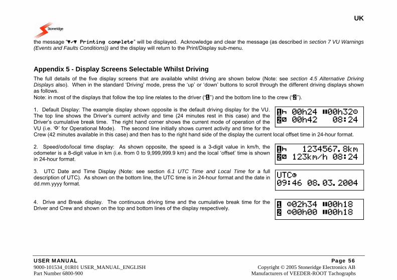
UK
USER MANUAL Page 56 9000-101534_01R01 USER_MANUAL_ENGLISH Copyright © 2005 Stoneridge Electronics AB Part Number 6800-900 Manufacturers of VEEDER-ROOT Tachographs
the message “ Printing complete” will be displayed. Acknowledge and clear the message (as described in section 7 VU Warnings (Events and Faults Conditions)) and the display will return to the Print/Display sub-menu.
Appendix 5 - Display Screens Selectable Whilst Driving The full details of the five display screens that are available whilst driving are shown below (Note: see section 4.5 Alternative Driving Displays also). When in the standard ‘Driving’ mode, press the ‘up’ or ‘down’ buttons to scroll through the different driving displays shown as follows. Note: in most of the displays that follow the top line relates to the driver (“”) and the bottom line to the crew (“”). 1. Default Display: The example display shown opposite is the default driving display for the VU. The top line shows the Driver’s current activity and time (24 minutes rest in this case) and the Driver’s cumulative break time. The right hand corner shows the current mode of operation of the VU (i.e. ‘’ for Operational Mode). The second line initially shows current activity and time for the Crew (42 minutes available in this case) and then has to the right hand side of the display the current local offset time in 24-hour format. 2. Speed/odo/local time display: As shown opposite, the speed is a 3-digit value in km/h, the odometer is a 8-digit value in km (i.e. from 0 to 9,999,999.9 km) and the local ‘offset’ time is shown in 24-hour format. 3. UTC Date and Time Display (Note: see section 6.1 UTC Time and Local Time for a full description of UTC). As shown on the bottom line, the UTC time is in 24-hour format and the date in dd.mm.yyyy format. 4. Drive and Break display. The continuous driving time and the cumulative break time for the Driver and Crew and shown on the top and bottom lines of the display respectively.
00h24 00h32 00h42 08:24
1234567.8km 123km/h 08:24
UTC 09:46 08.03.2004
02h34 00h18 00h00 00h18
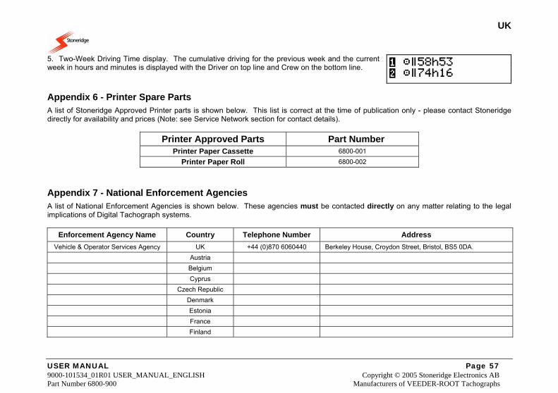
UK
USER MANUAL Page 57 9000-101534_01R01 USER_MANUAL_ENGLISH Copyright © 2005 Stoneridge Electronics AB Part Number 6800-900 Manufacturers of VEEDER-ROOT Tachographs
5. Two-Week Driving Time display. The cumulative driving for the previous week and the current week in hours and minutes is displayed with the Driver on top line and Crew on the bottom line.
Appendix 6 - Printer Spare Parts A list of Stoneridge Approved Printer parts is shown below. This list is correct at the time of publication only - please contact Stoneridge directly for availability and prices (Note: see Service Network section for contact details).
Printer Approved Parts Part Number Printer Paper Cassette 6800-001
Printer Paper Roll 6800-002
Appendix 7 - National Enforcement Agencies A list of National Enforcement Agencies is shown below. These agencies must be contacted directly on any matter relating to the legal implications of Digital Tachograph systems.
Enforcement Agency Name Country Telephone Number Address Vehicle & Operator Services Agency UK +44 (0)870 6060440 Berkeley House, Croydon Street, Bristol, BS5 0DA.
Austria Belgium Cyprus Czech Republic Denmark Estonia France Finland
58h53 74h16
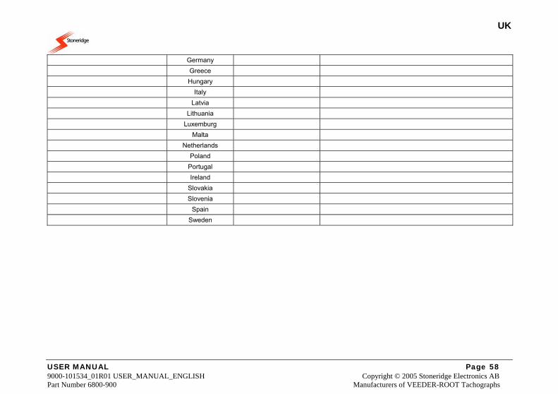
UK
USER MANUAL Page 58 9000-101534_01R01 USER_MANUAL_ENGLISH Copyright © 2005 Stoneridge Electronics AB Part Number 6800-900 Manufacturers of VEEDER-ROOT Tachographs
Germany Greece Hungary Italy Latvia Lithuania Luxemburg Malta Netherlands Poland Portugal Ireland Slovakia Slovenia Spain Sweden
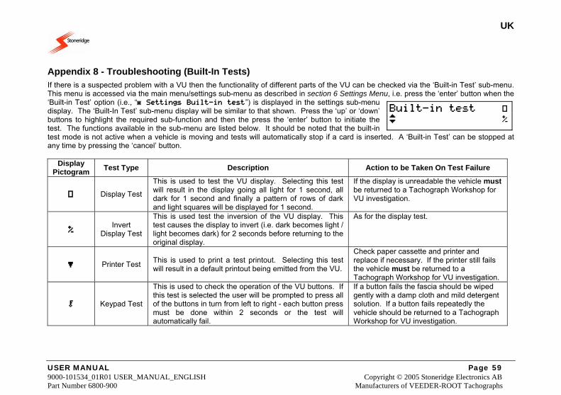
UK
USER MANUAL Page 59 9000-101534_01R01 USER_MANUAL_ENGLISH Copyright © 2005 Stoneridge Electronics AB Part Number 6800-900 Manufacturers of VEEDER-ROOT Tachographs
Appendix 8 - Troubleshooting (Built-In Tests) If there is a suspected problem with a VU then the functionality of different parts of the VU can be checked via the ‘Built-in Test’ sub-menu. This menu is accessed via the main menu/settings sub-menu as described in section 6 Settings Menu, i.e. press the ‘enter’ button when the ‘Built-in Test’ option (i.e., “ Settings Built-in test”) is displayed in the settings sub-menu display. The ‘Built-In Test’ sub-menu display will be similar to that shown. Press the ‘up’ or ‘down’ buttons to highlight the required sub-function and then the press the ‘enter’ button to initiate the test. The functions available in the sub-menu are listed below. It should be noted that the built-in test mode is not active when a vehicle is moving and tests will automatically stop if a card is inserted. A ‘Built-in Test’ can be stopped at any time by pressing the ‘cancel’ button.
Display Pictogram Test Type Description Action to be Taken On Test Failure
Display Test
This is used to test the VU display. Selecting this test will result in the display going all light for 1 second, all dark for 1 second and finally a pattern of rows of dark and light squares will be displayed for 1 second.
If the display is unreadable the vehicle must be returned to a Tachograph Workshop for VU investigation.
Invert Display Test
This is used test the inversion of the VU display. This test causes the display to invert (i.e. dark becomes light / light becomes dark) for 2 seconds before returning to the original display.
As for the display test.
Printer Test This is used to print a test printout. Selecting this test will result in a default printout being emitted from the VU.
Check paper cassette and printer and replace if necessary. If the printer still fails the vehicle must be returned to a Tachograph Workshop for VU investigation.
Keypad Test
This is used to check the operation of the VU buttons. If this test is selected the user will be prompted to press all of the buttons in turn from left to right - each button press must be done within 2 seconds or the test will automatically fail.
If a button fails the fascia should be wiped gently with a damp cloth and mild detergent solution. If a button fails repeatedly the vehicle should be returned to a Tachograph Workshop for VU investigation.
Built-in test
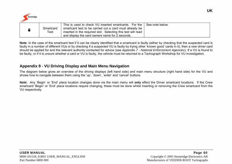
UK
USER MANUAL Page 60 9000-101534_01R01 USER_MANUAL_ENGLISH Copyright © 2005 Stoneridge Electronics AB Part Number 6800-900 Manufacturers of VEEDER-ROOT Tachographs
Smartcard Test
This is used to check VU inserted smartcards. For the smartcard test to be carried out a card must already be inserted in the required slot. Selecting this test will read and display the card owners name for 2 seconds.
See note below.
Note: In the case of the smartcard test if it can be clearly identified that a smartcard is faulty (either by checking that the suspected card is faulty in a number of different VUs or by checking if a suspected VU is faulty by trying other ‘known good’ cards in it), then a new driver card should be applied for and the relevant authority contacted for advice (see Appendix 7 - National Enforcement Agencies). If a VU is found to be faulty, or if it is unsure whether a card or VU is faulty, the vehicle must be returned to a Tachograph Workshop for VU investigation.
Appendix 9 - VU Driving Display and Main Menu Navigation The diagram below gives an overview of the driving displays (left hand side) and main menu structure (right hand side) for the VU and shows how to navigate between them using the ‘up’, ‘down’, ‘enter’ and ‘cancel’ buttons. Note: Any ‘Begin’ or ‘End’ place location changes done via the main menu will only effect the Driver smartcard locations. If the Crew smartcard ‘Begin’ or ‘End’ place locations require changing, these must be done whilst inserting or removing the Crew smartcard from the VU respectively.
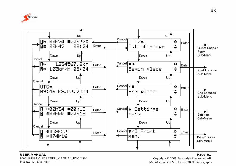
UK
USER MANUAL Page 61 9000-101534_01R01 USER_MANUAL_ENGLISH Copyright © 2005 Stoneridge Electronics AB Part Number 6800-900 Manufacturers of VEEDER-ROOT Tachographs
Cancel
Cancel
Cancel
Cancel
Cancel
Cancel
Cancel
Cancel
Cancel
Enter
Enter
Enter
Enter
Enter Out of Scope / Ferry Sub-Menu
Enter
Start Location Sub-Menu
Enter
End Location Sub-Menu
Enter
Settings Sub-Menu
Enter
Print/Display Sub-Menu
Enter
Up Up
Down Up Down Up
Down Up Down Up
Down Up Down Up
Down Up Down Up
00h24 00h32 00h42 08:24
OUT/ Out of scope
1234567.8km 123km/h 08:24
Begin place
UTC 09:46 08.03.2004
End place
02h34 00h18 00h00 00h18
Settings menu
58h53 74h16
/ Print menu
UK
USER MANUAL Page 62 9000-101534_01R01 USER_MANUAL_ENGLISH Copyright © 2005 Stoneridge Electronics AB Part Number 6800-900 Manufacturers of VEEDER-ROOT Tachographs
Down Down
Figure 11 Driving Displays and Main Menu Navigation
Appendix 10 - Glossary of Terms Listed below are explanations of common terms that are used throughout the manual. VU – this is the Digital Tachograph radio sized vehicle unit. Crew – this is the currently off-duty driver or co-driver in a dual-driver vehicle. Available – this is in-active time spent as Crew in a moving vehicle or time spent whilst a Driver is waiting to start driving (e.g. waiting for passengers to arrive or for paperwork to be completed). Work – this is non-driving active work (e.g. loading a vehicle). Long Press – this is pressing and holding a VU button for two seconds or more. Short Press – this is pressing and releasing a VU button in less than 1 second. Daily Work Period – this is the time from the start to the end of a drivers’ working day. Out of Scope – this is any driving carried out on a road that is not covered by EU Drivers’ hours laws. UTC – this is Universal time coordinated and is an incremental count of the number of elapsed seconds since 1st January 1970. Local Time – this is the time shown on the VU standard driving display and is the current time of the country in which driving is being done. Card Insertion Time – this is the time at which a smartcard was inserted into a VU i.e. when the drawer was closed. Card Withdrawal Time – this is the time at which a smartcard was withdrawn from a VU i.e. when the drawer was opened.

UK
USER MANUAL Page 63 9000-101534_01R01 USER_MANUAL_ENGLISH Copyright © 2005 Stoneridge Electronics AB Part Number 6800-900 Manufacturers of VEEDER-ROOT Tachographs
Tachograph Workshop – for the purposes of this manual, this is defined as any premises that has been approved to fit, replace, calibrate and inspect Stoneridge Vehicle Units.