
Stockham Cast Steel Valves
24
Stockham Cast Steel Valves
Transcript of Stockham Cast Steel Valves

Stockham Cast Steel ValvesStockham Cast Steel Valves


Cast Steel Valves
3
Performance in Any Application ......................................................................................................................4How to Specify and Order Valves ....................................................................................................................4Installation, Marking and Identification ...........................................................................................................5Gate Valves .....................................................................................................................................................6Globe Valves .................................................................................................................................................11Check Valves .................................................................................................................................................16
Figure No. Page15-OF-U ..........................................................................................................................................................830-OF-U ..........................................................................................................................................................960-OF-U ........................................................................................................................................................1015-GPF-U ......................................................................................................................................................1330-GPF-U ......................................................................................................................................................1460-GPF-U ......................................................................................................................................................1515-SF-U ........................................................................................................................................................1830-SF-U ........................................................................................................................................................1960-SF-U ........................................................................................................................................................20
Figure Number Index
Valve Type Class Stockham JenkinsGate 150 15-OF-U J1009B8F 300 30-OF-U J1010B8F 600 60-OF-U J1012B8FGlobe 150 15-GPF-U J1040B2 300 30-GPF-U J1042B2 600 60-GPF-U J1044B2Check 150 15-SF-U J1025B2 300 30-SF-U J1026B2 600 60-SF-U J1028B2
Figure Number Cross Reference
ContentsContents

4
Cast Steel Valves
Performance in Any Application
How to Specify and Order the Correct Valves
Care should be taken to select the most suitable steel valve for your service(s). Exact specification of each valve should be made to avoid ambiguity when requesting quotations or ordering the product.
SizeNominal size of the pipeline into which the valve will be placed must be determined. Comprehensive data on flow characteristics and pipe properties are available upon request from Stockham.
Valve MaterialThe following facts should be considered in determining the correct valve material.• The media to be controlled.• The temperature of the media.• The possible extraordinary stresses affecting the valve.• Safety standards and/or piping codes.
Pressure/Temperature RatingsPlease pay careful attention that the PRESSURE/TEMPERATURE RATINGS shown on page 21 are in keeping with the requirements of the service.
Valve End ConnectionsConsiderations as to pipeline integrity, future maintenance, corrosion factors, field assembly, weight and safety should be given in determining the method of connecting the valve in the pipeline.
CAUTION: When servicing, disassembling or disposing of valves containing asbestos gaskets or packing, avoid breathing dust or fibers from these parts. Disposal of asbestos and asbestos related products should comply with local, state and federal laws and regulations.
In any fluid handling system, valves are the controlling element: starting or stopping flow, regulating or throttling flow, preventing backflow, or relieving and regulating pressure.
Since Stockham valves are used in a variety of applications, the following descriptions may provide a basic guideline in the selection of steel valves.
Gate Valves
Globe Valves
Swing Check Valves
Gate valves serve as efficient stop valves with flow in either direction. They are commonly used where a minimum pressure drop is important. Throttling is not recommended because partially open gate valves exhibit flow characteristics not conducive to accurate and consistent flow control. Also, the valves may be damaged by the high velocity across the seats. They function best fully open or fully closed.
Gear Actuators recommended for Gate valves: Class 150: sizes above 10" Class 300: sizes above 8" Class 600: sizes above 6"
Globe valves are ideal for throttling service. Their flow characteristics permit accurate and repeatable flow control. However, caution must be exercised to avoid extremely close throttling when pressure drop exceeds 20%. This creates excessive noise, vibration and possible damage to valves and piping. When these conditions are anticipated, consult Stockham for recommendations.
Gear Actuators recommended for Globe valves: Class 150: sizes above 6" Class 300: sizes above 6" Class 600: sizes above 4"
Swing Check valves prevent reversal of flow through pipe lines. Most Stockham swing check valves can be installed in horizontal or vertical, upward flow, piping. They offer low resistance to flow and are particularly suited to low velocity service. The proper sizing of Check valves is critical to performance. Please refer to Page 17 or consult Stockham with flow conditions of your piping system for assistance in sizing.

5
Cast Steel Valves
Installation, Marking and Identification
CAST BODY MARKING:STOCKHAMSize 2, 2½, 3, 4...Class 150, 300, 600, 900Material Material Grade SymbolFactory ID Manufacturer's Identification SymbolPattern No. XXXXX (Optional)Foundry Symbol YYYY
NOTES:Cast lettering to be raised Gothic type.All stamped markings to be low stress.
ID TAG
CAST BONNET MARKING:Material SymbolPattern NumberFactory SymbolHeat Number (cast or stamped)(Not on flange edge unless recessed.)
Ring Joint Number (stamped) when applicable
Serial Number (stamped)
Marking and identification of Stockham steel valves conforms to ASME B16.34 and MSS SP-25.
It is important to properly identify valves in service to allow for the ordering of replacement parts or address questions or concerns relating to our products. Body markings and information shown on the identification plate helps to properly identify valves, allowing timely and accurate responses to such inquiries.
Integrally cast body marking data includes the following information and helps to provide traceability: • Stockham name • Pressure class • Valve size • “Steel” symbol for the grade of material (i.e., WCB for carbon steel) • Heat number – on body and bonnet (cast or stamped) • Individual serializationThe body markings are supplemented by an identification plate which, depending on valve type and size, is mounted in the most practicable position. Tag location for
Product Marking
I.D. Tag Marking Information
gate and globe valves is typically on the valve yoke or body/bonnet flange. Check valve tags are typically mounted on the rim of the cap.
Identification plates bear the following information: • Catalog number • Valve size • Body material • Disc material • Stem material • Seat and trim material • Pressure and temperature rating
When purchasing valves, reference should also be made to MSS SP-92 “Valve Users Guide.” Inquiries relating specifically to Stockham products may be referred to our factory or customer service department.
6
Cast Steel Gate Valves
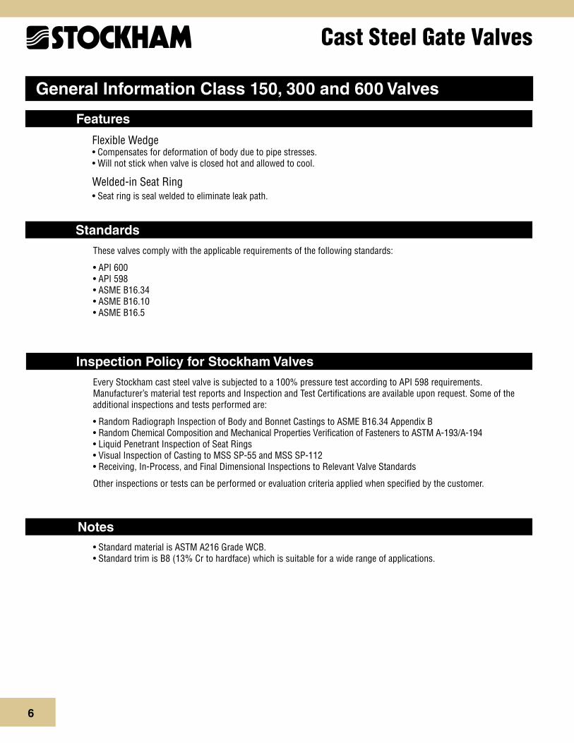
General Information Class 150, 300 and 600 Valves
These valves comply with the applicable requirements of the following standards:
• API 600 • API 598 • ASME B16.34 • ASME B16.10 • ASME B16.5
• Standard material is ASTM A216 Grade WCB. • Standard trim is B8 (13% Cr to hardface) which is suitable for a wide range of applications.
Features
Standards
Notes
Flexible Wedge • Compensates for deformation of body due to pipe stresses. • Will not stick when valve is closed hot and allowed to cool.
Welded-in Seat Ring • Seat ring is seal welded to eliminate leak path.
Every Stockham cast steel valve is subjected to a 100% pressure test according to API 598 requirements. Manufacturer’s material test reports and Inspection and Test Certifications are available upon request. Some of the additional inspections and tests performed are:
• Random Radiograph Inspection of Body and Bonnet Castings to ASME B16.34 Appendix B • Random Chemical Composition and Mechanical Properties Verification of Fasteners to ASTM A-193/A-194 • Liquid Penetrant Inspection of Seat Rings • Visual Inspection of Casting to MSS SP-55 and MSS SP-112 • Receiving, In-Process, and Final Dimensional Inspections to Relevant Valve Standards
Other inspections or tests can be performed or evaluation criteria applied when specified by the customer.
Inspection Policy for Stockham Valves

7
Cast Steel Gate Valves
Typical Bolted Bonnet Gate Features
1. Body: Body is cast to provide liberal strength to meet operating conditions and to permit unobstructed flow. Turbulence, erosion and pressure drop are minimized.
Flanged End - Stockham cast steel gate valves are available in flanged end. All flanged end valves are designed to conform to ASME B16.5 and ASME B16.34 standards.
2. Integral Yoke & Bonnet: Some designs incorporate a two-piece bonnet and yoke. All bonnet assemblies are cast and finished to the same exacting tolerances as the bodies for accurate alignment of stems and ease of sealing. Bonnet joint varies from flat face gasket-joint to ring-type bonnet joint, depending on class.
3. Seat Rings: Seat rings are seal welded to eliminate leak path behind rings and for long trouble-free service. The surfaces are precision ground to fit accurately with the disc.
4. Disc: One piece flexible disc provides accurate alignment of mating seating surfaces so the valve can absorb piping strains without leakage. Also, it avoids any tendency to stick in the seated position.
5. Stem: The tee-head disc-stem connection prevents lateral strain on the stem for smooth, easy operation. Accurately cut threads engage the yoke sleeve for positive control of disc position.
6. Yoke Sleeve
7. Handwheel Nut
8. Yoke Sleeve Retaining Nut
9. Packing: Packing contains corrosion inhibitor to avoid stem pitting. Stuffing box is deep, assuring long packing life.
10. Gland: Gland is a two-piece ball-type which exerts even pressure on the packing without binding the stem.
11. Gland Flange
12. Gland Eye Bolts: Eyebolts swing aside for ease in repacking the stuffing box.
13. Gland Eye Bolt Nuts
14. Bonnet Gasket
15. Bonnet Studs: Number is dependent on valve size and class.
16. Bonnet Nuts: Number is dependent on valve size and class.
17. Gland Eyebolt Pins
18. Bonnet Bushing
19. Handwheel: Stockham gate valves can also be supplied with gear or motor operators.
20. Hydraulic Grease Fitting: Hydraulic grease fitting provides for lubrication of yoke sleeve bearing surfaces (not shown).
Stockham gate valves offer the ultimate in dependable service for steam, air, gas, oil, oil vapor, and high pressure installations. All have straight-through ports to assure minimum turbulence, erosion, and resistance to flow. They are available in a wide variety of trims.
NOTE: Stockham recommends the use of gear assistance for certain multi-turn valves for optimal functional performance in larger sizes and high flow-rate applications. Please refer to the note on specific product pages.

8
Cast Steel Gate ValvesFigure 15-OF-U
Class 150 • Outside Screw & Yoke • Flexible Wedge Disc
Figure 15-OF-UFlanged
Size Range:2 through 24 inches (50 - 600 mm)
Pressure Temperature RatingCarbon SteelASTM A216 Grade WCB285 psi @ -20°F to 100°F(20 bar @ -28°C to 37°C)
Material of Construction*Description Material
Body WCB
Bonnet WCB
Seat Rings Hardfaced
Disc CA-15 or 13% CR Overlay
Stem 410 SS
Packing Graphite
Bonnet Gasket Corrugated Soft Steel or Steel/Stainless Steel w/Graphite
Back Seat 410 SS
Yoke Sleeve D2 Ni-Resist
Retaining Nut Malleable or Steel
Gland Steel
Gland Flange Steel
Eye Bolt Steel
Eye Bolt Nuts Steel
Pins Steel
Bonnet Studs A193 Gr. B7
Bonnet Nuts A194 Gr. 2H
Handwheel Malleable, Ductile or Steel
Handwheel Nut Ductile or Steel
I.D. Tags SS
I.D. Pins Steel
Spacer Steel
Grease Fittings Steel
C
B
A
NOTES: *Standard construction: WCB-Trim 8, other options are available.Stockham recommends the use of manual or powered gear assistance for sizes 10" and larger.
Steel Valves ASME B16.34
Face-to-Face ASME B16.10
Flange Dimensions ASME B16.5
Basic Design API 600
Testing API 598
Industry Standards
Dimensions and WeightsInches (millimeters) - pounds (kilograms) Valves 2 2 ½ 3 4 6 8 10 12 14 16 18 20 24 (50) (65) (80) (100) (150) (200) (250) (300) (350) (400) (450) (500) (600)
A 7.00 7.50 8.00 9.00 10.50 11.50 13.00 14.00 15.00 16.00 17.00 18.00 20.00 (178) (191) (203) (229) (267) (292) (330) (356) (381) (406) (432) (457) (508) B 17 17 19 23 31 39 47 55 61 71 78 90 99 (Open) (432) (432) (483) (584) (787) (990) (1193) (1397) (1549) (1803) (1981) (2286) (2515)
C 8 8 9 10 12 14 16 18 22 24 25 27 30 (203) (203) (229) (254) (305) (356) (406) (457) (559) (610) (635) (686) (762)
Wt. 49 55 74 110 192 300 420 630 905 1260 1590 2580 3240 (22) (25) (33) (50) (87) (136) (190) (285) (410) (571) (721) (1170) (1469)

9
Cast Steel Gate ValvesFigure 30-OF-U
Class 300 • Outside Screw & Yoke • Flexible Wedge Disc
Figure 30-OF-UFlanged
Size Range:2 through 24 inches (50 - 600 mm)
Pressure Temperature RatingCarbon SteelASTM A216 Grade WCB740 psi @ -20°F to 100°F(51 bar @ -28°C to 37°C)
B
A
C
Material of Construction*Description Material
Body WCB
Bonnet WCB
Seat Rings Hardfaced
Disc CA-15 or 13% CR Overlay
Stem 410 SS
Packing Graphite
Bonnet Gasket Stainless Steel spiral wound Graphite
Back Seat 410 SS
Yoke Sleeve D2 Ni-Resist
Retaining Nut Malleable or Steel
Gland Steel
Gland Flange Steel
Eye Bolt Steel
Eye Bolt Nuts Steel
Pins Steel
Bonnet Studs A193 Gr. B7
Bonnet Nuts A194 Gr. 2H
Handwheel Malleable, Ductile or Steel
Handwheel Nut Ductile or Steel
I.D. Tags SS
I.D. Pins Steel
Spacer Steel
Grease Fittings Steel
NOTES: *Standard construction: WCB-Trim 8, other options are available.Stockham recommends the use of manual or powered gear assistance for sizes 8" and larger.
Dimensions and WeightsInches (millimeters) - pounds (kilograms) Valves 2 2 ½ 3 4 6 8 10 12 14 16 18 20 24 (50) (65) (80) (100) (150) (200) (250) (300) (350) (400) (450) (500) (600)
A 8.50 9.50 11.12 12.00 15.88 16.50 18.00 19.75 30.00 33.00 36.00 39.00 45.00 (216) (241) (282) (305) (403) (419) (457) (502) (762) (838) (914) (990) (1143) B 18 18 21 24 33 42 50 58 62 71 79 85 100 (Open) (457) (457) (533) (609) (838) (1066) (1270) (1473) (1574) (1803) (2006) (2154) (2540)
C 8 8 9 10 14 16 18 20 22 24 25 30 30 (203) (203) (229) (254) (356) (406) (457) (508) (559) (610) (635) (762) (762)
Wt. 69 77 112 165 310 500 760 1050 1530 2380 2722 3650 5115 (31) (34) (50) (74) (140) (226) (344) (476) (693) (1079) (1234) (1655) (2320)
Steel Valves ASME B16.34
Face-to-Face ASME B16.10
Flange Dimensions ASME B16.5
Basic Design API 600
Testing API 598
Industry Standards

10
Cast Steel Gate ValvesFigure 60-OF-U
Class 600 • Outside Screw & Yoke • Flexible Wedge Disc
Figure 60-OF-UFlanged
Size Range:2 through 12 inches (50 - 300 mm)
Pressure Temperature RatingCarbon SteelASTM A216 Grade WCB1480 psi @ -20°F to 100°F(102 bar @ -28°C to 37°C)
B
A
C
Steel Valves ASME B16.34
Face-to-Face ASME B16.10
Flange Dimensions ASME B16.5
Basic Design API 600
Testing API 598
Industry Standards
Material of Construction*Description Material
Body WCB
Bonnet WCB
Seat Rings Hardfaced
Disc CA-15 or 13% CR Overlay
Stem 410 SS
Packing Graphite
Bonnet Gasket Ring Type Joint
Back Seat 410 SS
Yoke Sleeve D2 Ni-Resist
Retaining Nut Malleable or Steel
Gland Steel
Gland Flange Steel
Eye Bolt Steel
Eye Bolt Nuts Steel
Pins Steel
Bonnet Studs A193 Gr. B7
Bonnet Nuts A194 Gr. 2H
Handwheel Malleable, Ductile or Steel
Handwheel Nut Ductile or Steel
I.D. Tags SS
I.D. Pins Steel
Spacer Steel
Grease Fittings Steel
Dimensions and WeightsInches (millimeters) - pounds (kilograms) Valves 2 2 ½ 3 4 6 8 10 12 (50) (65) (80) (100) (150) (200) (250) (300)
A 11.50 13.00 14.00 17.00 22.00 26.00 31.00 33.00 (292) (330) (355) (431) (558) (660) (787) (838) B 17 19 23 27 36 42 51 58 (Open) (431) (482) (584) (685) (914) (1066) (1295) (1473)
C 10 10 12 14 18 20 25 27 (254) (254) (304) (355) (457) (508) (635) (685)
Wt. 99 121 170 280 590 1080 1660 2070 (44) (54) (77) (127) (267) (489) (752) (938)
NOTES: *Standard construction: WCB-Trim 8, other options are available.Stockham recommends the use of manual or powered gear assistance for sizes 6" and larger.

11
Cast Steel Globe Valves
General Information Class 150, 300 and 600 Valves
Welded-in Seat Ring • Seat ring is seal welded to eliminate leak path.
• Standard material is ASTM A216 Grade WCB. • Standard trim is B2 (13% Cr to hardface) which is suitable for a wide range of applications.
Features
Basic Standards
Notes
These valves comply with the applicable requirements of the following standards:
• API 598 • ASME B16.34 • ASME B16.10 • ASME B16.5

12
Cast Steel Globe Valves
Typical Globe Valve Features
Stockham globe valves are highly efficient for services requiring frequent operation and throttling when pressure drop across the valve is about 20% of inlet pressure. Closer throttling, creating higher pressure drops may cause cavitation or excessive velocities which could cause high noise levels, vibration and possible damage to the valve or adjacent piping. Globe valves can be equipped with optional operators and are available with a variety of trims to match service requirements.
1. Body: Body is cast with heavy sections reinforced at points subjected to the greatest stress. Valves are available in flanged ends. All conform to referenced ASME specifications.
2. Bonnet
3. Seat Ring
4. Disc
5. Disc Stem Nut: Disc Stem Ring connects the disc to the stem, permitting the disc to swivel and aid in securing tight seating for trouble-free service.
6. Disc Washer
7. Stem: Stem has long engagement with yoke bushing for accurate seating.
8. Bonnet Bushing
9. Yoke Bushing
10. Wheel Nut
11. Packing
12. Gland: Gland is a two-piece, ball-type which exerts even pressure on the packing without binding the stem.
13. Gland Flange
14. Gland Eye Bolts: Eye bolts are securely fastened to the bonnet yet swing away to permit easy access to the stuffing box.
15. Bonnet Gasket: Bonnet gasket provides a positive seal against leakage. Class 150 and 300 valves have a male/female bonnet joint. A ring-type gasket is employed in Class 600.
16. Bonnet Studs
17. Bonnet Nuts
18. Pin
19. Handwheel
NOTE: Stockham recommends the use of gear assistance for certain multi-turn valves for optimal functional performance in larger sizes and high flow-rate applications. Please refer to the note on specific product pages.

13
Cast Steel Globe ValvesFigure 15-GPF-U
Class 150 • Outside Screw & Yoke • Bolted Bonnet
Figure 15-GPF-UFlanged
Size Range:2 through 12 inches(50 - 300 mm)
Pressure Temperature RatingCarbon SteelASTM A216 Grade WCB285 psi @ -20°F to 100°F(20 bar @ -28°C to 37°C)
C
B
A
Steel Valves ASME B16.34
Face-to-Face ASME B16.10
Flange Dimensions ASME B16.5
Testing API 598
Industry Standards
Material of Construction*Description Material
Body WCB
Bonnet WCB
Seat Rings Hardfaced
Disc 13% CR Overlay
Stem 410 SS
Packing Graphite
Bonnet Gasket Corrugated Soft Steel or Steel/Stainless Steel w/Graphite
Back Seat 410 SS
Disc Stem Nut 410 SS
Disc Washer Carbon Steel
Gland 410 SS
Gland Flange WCB
Eye Bolt Steel
Eye Bolt Nuts A563 Gr. A or O
Pins _
Bonnet Studs A193 Gr. B7
Bonnet Nuts A194 Gr. 2H
Handwheel WCB
Handwheel Nut A194 Gr. 2H
I.D. Tags SS
I.D. Pins Steel
Dimensions and WeightsInches (millimeters) - pounds (kilograms) Valves 2 2 ½ 3 4 6 8 10 12 (50) (65) (80) (100) (150) (200) (250) (300)
A 8.00 8.50 9.50 11.50 16.00 19.50 24.50 27.50 (203) (216) (241) (292) (406) (495) (622) (698) B 14 16 16 19 21 24 29 40 (Open) (356) (406) (406) (482) (533) (610) (736) (1016)
C 8 8 10 12 14 18 20 24 (203) (203) (254) (304) (355) (457) (508) (610)
Wt. 48 70 92 132 223 355 640 1100 (21) (31) (41) (59) (101) (161) (290) (498)
NOTES: *Standard construction: WCB-Trim 8, other options are available.Stockham recommends the use of manual or powered gear assistance for sizes 6" and larger.

14
Cast Steel Globe ValvesFigure 30-GPF-U
Class 300 • Outside Screw & Yoke • Bolted Bonnet
Material of Construction*Description Material
Body WCB
Bonnet WCB
Seat Rings Hardfaced
Disc 13% CR Overlay
Stem 410 SS
Packing Graphite
Bonnet Gasket Stainless Steel spiral wound Graphite
Back Seat 410 SS
Disc Stem Nut 410 SS
Disc Washer Carbon Steel
Gland 410 SS
Gland Flange WCB
Eye Bolt Steel
Eye Bolt Nuts A563 Gr. A or O
Pins _
Bonnet Studs A193 Gr. B7
Bonnet Nuts A194 Gr. 2H
Handwheel WCB
Handwheel Nut A194 Gr. 2H
I.D. Tags SS
I.D. Pins Steel
Dimensions and WeightsInches (millimeters) - pounds (kilograms) Valves 2 2 ½ 3 4 6 8 10 12 (50) (65) (80) (100) (150) (200) (250) (300)
A 10.50 11.50 12.50 14.00 17.50 22.00 24.50 28.00 (267) (292) (317) (356) (444) (558) (622) (711) B 15 18 18 21 25 36 41 51 (Open) (381) (457) (457) (533) (635) (914) (1041) (1295)
C 8 10 10 14 18 22 24 25 (203) (254) (254) (355) (457) (559) (610) (635)
Wt. 69 99 128 190 330 330 700 1360 (31) (44) (58) (86) (149) (149) (317) (616)
NOTES: *Standard construction: WCB-Trim 8, other options are available.Stockham recommends the use of manual or powered gear assistance for sizes 6" and larger.
Figure 30-GPF-UFlanged
Size Range:2 through 12 inches(50 - 300 mm)
Pressure Temperature RatingCarbon SteelASTM A216 Grade WCB740 psi @ -20°F to 100°F(51 bar @ -28°C to 37°C)
C
B
A
Steel Valves ASME B16.34
Face-to-Face ASME B16.10
Flange Dimensions ASME B16.5
Testing API 598
Industry Standards

15
Cast Steel Globe ValvesFigure 60-GPF-U
Class 600 • Outside Screw & Yoke • Bolted Bonnet
Material of Construction*Description Material
Body WCB
Bonnet WCB
Seat Rings Hardfaced
Disc 13% CR Overlay
Stem 410 SS
Packing Graphite
Bonnet Gasket Ring Type Joint
Back Seat 410 SS
Disc Stem Nut 410 SS
Disc Washer Carbon Steel
Gland 410 SS
Gland Flange WCB
Eye Bolt Steel
Eye Bolt Nuts A563 Gr. A or O
Pins _
Bonnet Studs A193 Gr. B7
Bonnet Nuts A194 Gr. 2H
Handwheel WCB
Handwheel Nut A194 Gr. 2H
I.D. Tags SS
I.D. Pins Steel
Dimensions and WeightsInches (millimeters) - pounds (kilograms) Valves 2 2 ½ 3 4 6 8 (50) (65) (80) (100) (150) (200)
A 11.50 13.00 14.00 17.00 22.00 26.00 (292) (330) (356) (431) (558) (660) B 19 21 23 27 33 36 (Open) (482) (533) (584) (685) (838) (914)
C 10 10 14 18 20 26 (254) (254) (355) (457) (508) (660)
Wt. 126 154 188 270 890 990 (57) (69) (85) (122) (403) (449)
NOTES: *Standard construction: WCB-Trim 8, other options are available.Stockham recommends the use of manual or powered gear assistance for sizes 4" and larger.
Figure 60-GPF-UFlanged
Size Range:2 through 8 inches(50 - 200 mm)
Pressure Temperature RatingCarbon SteelASTM A216 Grade WCB1480 psi @ -20°F to 100°F(102 bar @ -28°C to 37°C)
C
B
A
Steel Valves ASME B16.34
Face-to-Face ASME B16.10
Flange Dimensions ASME B16.5
Testing API 598
Industry Standards

16
Cast Steel Check Valves
General Information Class 150, 300 and 600 Valves
Disc Type • For class 600 valves, a ring joint bonnet gasket assures positive seal against leakage and accurate alignment of moving parts
Welded-in Seat Ring • Seat ring is seal welded to eliminate leak path.
These valves comply with the applicable requirements of the following standards:
• API 598 • ASME B16.34 • ASME B16.10 • ASME B16.5
• Standard material is ASTM A216 Grade WCB. • Standard trim is B2 (13% Cr to hardface) which is suitable for a wide range of applications.
Features
Standards
Notes

17
Cast Steel Check Valves
Typical Swing Check Valve Features
Body:1. Strong construction assures maximum safety over the recommended pressure and temperature range.
Cap:2. permits access to hinge and disc without removing valve from line.
Disc:3. is designed to close on its own weight to stop backflow from gaining sufficient velocity to create damaging shock.
Disc Nut Pin: 4. retained by physical deformation or welding.
Hinge5.
Cap Stud6.
Cap Stud Nuts7.
Cap Gasket8.
Body Seat Ring9. (welded in)
Disc Washer10.
Disc Nut11.
NOTE: The above sketch is generic. Valve supplied may be internal hung or external hung type units depending upon pressure class and size.
Check valves are automatically actuated. They are opened and sustained in the open position by the force of velocity pressure, and closed by the force of gravity. Seating load and resultant tightness is dependent upon back pressure. The disc and associated moving parts may be in a constant state of movement if the velocity pressure is not sufficient to hold the valve in a wide open and stable position. Premature wear and noisy operation or vibration of the moving parts can be avoided by selecting the size of check valve on the basis of flow conditions. The minimum velocity required to hold a swing check valve in the wide open and stable position has been developed by analysis of extensive test data and is expressed by the formula:
The value for v is equal to flow in feet per second and v is the specific volume of fluid in cubic feet per pound. Sizing swing check valves on this basis may often result in the use of valves that are smaller than the pipe in which they are used, necessitating the use of reducers for installation. The pressure drop will be no greater than that of the larger valve that is only partially open, and valve life will be greatly extended. The added bonus, of course, is the lower cost of the smaller valve.
There is no tendency for the seating surfaces of swing check valves to gall or score, because the disc meets the flat seat squarely without rubbing contact upon closing.
Stockham cast steel swing check valves can be furnished with outside lever and adjustable weight in certain sizes when so ordered. With the lever and weight mounted so that the weight assists the disc in closing, the valve closes more rapidly when flow stops, thus minimizing reversal of flow and resultant surge and shock. With the lever and weight mounted to balance the weight of the disc, the valve becomes more sensitive to low flow velocities. For more information about the size range for which this modification is available, please consult your local sales representative or customer service office.
Swing check valves are used to prevent reversal of flow in horizontal pipelines. Stockham does not recommend the use of swing check valves in vertical pipelines; however when using this style of valve in a vertical application, the valve must be installed for upward flow only.
v = 60 √ v

18
Cast Steel Check ValvesFigure 15-SF-U
Class 150 • Bolted Cap
Figure 15-SF-UFlanged
Size Range:2 through 24 inches(50 - 600 mm)
Pressure Temperature RatingCarbon SteelASTM A216 Grade WCB285 psi @ -20°F to 100°F(20 bar @ -28°C to 37°C)
B
A
Steel Valves ASME B16.34
Face-to-Face ASME B16.10
Flange Dimensions ASME B16.5
Testing API 598
Industry Standards
Material of Construction*Description Material
Body WCB
Cap WCB
Seat Ring Hardfaced
Disc 13% CR Overlay
Hinge WCB
Pins, Hinge 410 SS
Disc Washer Steel
Cap Screw A307 Gr. B
Cap Gasket Corrugated Soft Steel or Steel/Stainless Steel w/Graphite
Cap Studs A193 Gr. B7
Cap Nuts A194 Gr. 2H
I.D. Tags SS
I.D. Pins Steel
NOTE: *Standard construction: WCB-Trim 8, other options are available.
Dimensions and WeightsInches (millimeters) - pounds (kilograms) Valves 2 2 ½ 3 4 6 8 10 12 14 16 18 20 24 (50) (65) (80) (100) (150) (200) (250) (300) (350) (400) (450) (500) (600)
A 8.00 8.50 9.50 11.50 14.00 19.50 24.50 27.50 31.00 34.00 38.50 38.50 51.00 (203) (216) (241) (292) (356) (495) (622) (698) (787) (863) (977) (977) (1295) B 9 7 7 9 11 13 15 17 15 17 18 19 22 (Open) (229) (178) (178) (229) (279) (330) (381) (432) (381) (432) (457) (482) (558)
Wt. 41 57 64 101 170 360 485 765 950 1225 1700 1850 2600 (18) (25) (29) (45) (77) (163) (219) (346) (430) (555) (771) (839) (1179)

19
Cast Steel Check ValvesFigure 30-SF-U
Class 300 • Bolted Cap
Figure 30-SF-UFlanged
Size Range:2 through 24 inches(50 - 600 mm)
Pressure Temperature RatingCarbon SteelASTM A216 Grade WCB740 psi @ -20°F to 100°F(51 bar @ -28°C to 37°C)
B
A
Steel Valves ASME B16.34
Face-to-Face ASME B16.10
Flange Dimensions ASME B16.5
Testing API 598
Industry Standards
Material of Construction*Description Material
Body WCB
Cap WCB
Seat Ring Hardfaced
Disc 13% CR Overlay
Hinge WCB
Pins, Hinge 410 SS
Disc Washer Steel
Cap Screw A307 Gr. B
Cap Gasket Stainless Steel spiral wound Graphite
Cap Studs A193 Gr. B7
Cap Nuts A194 Gr. 2H
I.D. Tags SS
I.D. Pins Steel
Dimensions and WeightsInches (millimeters) - pounds (kilograms) Valves 2 2 ½ 3 4 6 8 10 12 14 16 18 20 24 (50) (65) (80) (100) (150) (200) (250) (300) (350) (400) (450) (500) (600)
A 10.50 11.50 12.50 14.00 17.50 21.00 24.50 28.00 33.00 34.00 38.50 40.00 53.00 (266) (292) (317) (356) (444) (533) (622) (711) (838) (863) (977) (1016) (1346) B 7 8 8 9 11 14 16 19 19 22 23 25 30 (Open) (178) (203) (203) (229) (279) (355) (406) (482) (482) (558) (584) (635) (762)
Wt. 46 66 86 154 276 460 675 860 1500 1850 2250 2900 4350 (20) (29) (39) (69) (125) (208) (306) (390) (680) (839) (1020) (1315) (1973)
NOTE:*Standard construction: WCB-Trim 8, other options are available.
20
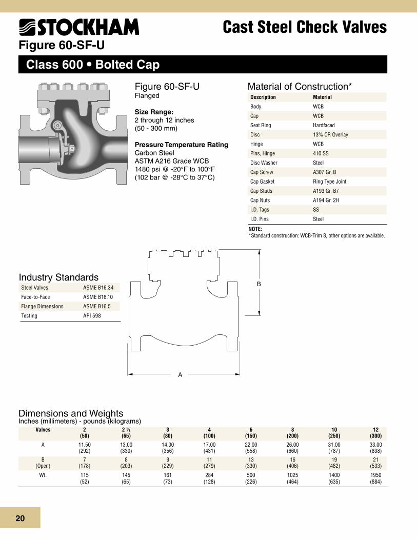
Cast Steel Check ValvesFigure 60-SF-U
Class 600 • Bolted Cap
Figure 60-SF-UFlanged
Size Range:2 through 12 inches(50 - 300 mm)
Pressure Temperature RatingCarbon SteelASTM A216 Grade WCB1480 psi @ -20°F to 100°F(102 bar @ -28°C to 37°C)
B
A
Steel Valves ASME B16.34
Face-to-Face ASME B16.10
Flange Dimensions ASME B16.5
Testing API 598
Industry Standards
Material of Construction*Description Material
Body WCB
Cap WCB
Seat Ring Hardfaced
Disc 13% CR Overlay
Hinge WCB
Pins, Hinge 410 SS
Disc Washer Steel
Cap Screw A307 Gr. B
Cap Gasket Ring Type Joint
Cap Studs A193 Gr. B7
Cap Nuts A194 Gr. 2H
I.D. Tags SS
I.D. Pins Steel
NOTE: *Standard construction: WCB-Trim 8, other options are available.
Dimensions and WeightsInches (millimeters) - pounds (kilograms) Valves 2 2 ½ 3 4 6 8 10 12 (50) (65) (80) (100) (150) (200) (250) (300)
A 11.50 13.00 14.00 17.00 22.00 26.00 31.00 33.00 (292) (330) (356) (431) (558) (660) (787) (838) B 7 8 9 11 13 16 19 21 (Open) (178) (203) (229) (279) (330) (406) (482) (533)
Wt. 115 145 161 284 500 1025 1400 1950 (52) (65) (73) (128) (226) (464) (635) (884)
21
Cast Steel Valves
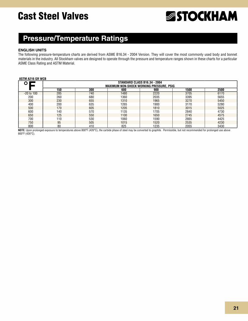
ENGLISH UNITSThe following pressure-temperature charts are derived from ASME B16.34 - 2004 Version. They will cover the most commonly used body and bonnet materials in the industry. All Stockham valves are designed to operate through the pressure and temperature ranges shown in these charts for a particular ASME Class Rating and ASTM Material.
ASTM A216 GR WCBSTANDARD CLASS B16.34 - 2004
MAXIMUM NON-SHOCK WORKING PRESSURE, PSIG150 300 600 900 1500 2500
-20 to 100 285 740 1480 2220 3705 6170200 260 680 1360 2035 3395 5655300 230 655 1310 1965 3270 5450400 200 635 1265 1900 3170 5280500 170 605 1205 1810 3015 5025600 140 570 1135 1705 2840 4730650 125 550 1100 1650 2745 4575700 110 530 1060 1590 2665 4425750 95 505 1015 1520 2535 4230800 80 410 825 1235 2055 3430
°F
NOTE: Upon prolonged exposure to temperatures above 800°F (426°C), the carbide phase of steel may be converted to graphite. Permissible, but not recommended for prolonged use above 800°F (426°C).
Pressure/Temperature Ratings

2222
Cast Steel Valves
Notes


CRANE Energy Global Headquarters19241 David Memorial Drive, Suite 150
Shenandoah, Texas 77385 Tel: +1-936-271-6500Fax: +1-936-271-6510
www.craneenergy.com
CRANE Energy Flow Solutions®
brands you know...technology you want...solutions you need
EG-SC-CT-EN-L11-03-1005 (CV-807)
Aloyco, Center Line, Compac-Noz, Crane, Duo-Chek, Flowseal, Jenkins, Krombach, Noz-Chek, Pacific, Stockham, Triangle, and Uni-Chek are all trademarks of Crane Co. ©2010
Ball, Check, Corrosion Resistant Gate and Globe Valves
Lined Check and Resilient Seated Butterfly Valves
Ball, Bronze, Butterfly, Cast Steel, and Iron Valves
High Performance Wafer Check Valves
High Performance Butterfly and Metal Seated Valves
Ball, Bronze, Butterfly, Cast Steel, and Iron Valves
Nozzle-Type, Severe Service Check Valves
High Pressure and Severe Service Valves
Ball, Bronze, Butterfly, Cast Steel, and Iron Valves
Cast Steel Valves
Certified Valve Repair Services
®
PACIFIC VALVES
Valve System Solutions, Highly Engineered Specialty Valves
STOCKHAM Customer Service2129 3rd Avenue, S.E.
Cullman, Alabama 35055Tel: +1-800-STOCKHAM
Fax: +1-256-775-3860