STMS1U INSTALLATION INSTRUCTIONS - …downloads.chiefmfg.com/manuals-i/STMS1U-I.pdfSTMS1U...
12
INSTALLATION INSTRUCTIONS FUSION SMALL SINGLE STUD FLAT PANEL MOUNT Spanish Product Description /German Product Description Portuguese Product Description Italian Product Description STMS1U
Transcript of STMS1U INSTALLATION INSTRUCTIONS - …downloads.chiefmfg.com/manuals-i/STMS1U-I.pdfSTMS1U...

I N S T A L L A T I O N I N S T R U C T I O N S
FUSION SMALL SINGLE STUDFLAT PANEL MOUNT
Spanish Product Description/German Product Description
Portuguese Product Description Italian Product Description
STMS1U

STMS1U Installation Instructions
2
DISCLAIMERMilestone AV Technologies and its affiliated corporations andsubsidiaries (collectively “Milestone”), intend to make thismanual accurate and complete. However, Milestone makes noclaim that the information contained herein covers all details,conditions or variations, nor does it provide for every possiblecontingency in connection with the installation or use of thisproduct. The information contained in this document is subjectto change without notice or obligation of any kind. Milestonemakes no representation of warranty, expressed or implied,regarding the information contained herein. Milestone assumesno responsibility for accuracy, completeness or sufficiency ofthe information contained in this document.
Chief® is a registered trademark of Milestone AV Technologies.All rights reserved.
DEFINITIONSMOUNTING SYSTEM: A MOUNTING SYSTEM is theprimary Chief product to which an accessory and/or componentis attached.
ACCESSORY: AN ACCESSORY is the secondary Chiefproduct which is attached to a primary Chief product, and mayhave a component attached or setting on it.
COMPONENT: A COMPONENT is an audiovisual itemdesigned to be attached or resting on an accessory or mountingsystem such as a video camera, CPU, screen, display,projector, etc.
WARNING: A WARNING alerts you to the possibility ofserious injury or death if you do not follow the instructions.
CAUTION: A CAUTION alerts you to the possibility ofdamage or destruction of equipment if you do not follow thecorresponding instructions.
IMPORTANT SAFETY INSTRUCTIONS
WARNING: Failure to read, thoroughly understand, andfollow all instructions can result in serious personal injury,damage to equipment, or voiding of factory warranty! It is theinstaller’s responsibility to make sure all mounting systemsare properly assembled and installed using the instructionsprovided.
WARNING: Failure to provide adequate structural strengthfor this mounting system can result in serious personal injuryor damage to equipment! It is the installer’s responsibility tomake sure the structure to which this mounting system isattached can support five times the combined weight of allequipment. Reinforce the structure as required beforeinstalling the mounting system.
WARNING: Exceeding the weight capacity can result inserious personal injury or damage to equipment! It is theinstaller’s responsibility to make sure the combined weight ofall components and accessories attached to the STMS1Udoes not exceed 75 lbs (34.02 kg).
WARNING: Use this mounting system only for its intendeduse as described in these instructions. Do not useattachments not recommended by the manufacturer.
WARNING: Never operate this mounting system if it isdamaged. Return the mounting system to a service center forexamination and repair.
WARNING: Do not use this mounting system outdoors.
IMPORTANT ! : The STMS1U mounts are designed to bemounted to:
• a bare 8" thick concrete or 8"x8"x16" concrete blockwall with NO drywall, or
• a 2" x 4" wood stud wall covered by drywall withmaximum thickness of 5/8":
--SAVE THESE INSTRUCTIONS--

Installation Instructions STMS1U
3
DIMENSIONS
DIMENSIONS: INCHES [MILLIMETERS]
12.00304.8
1.0827.5
6.00152.3
6.00152.4
6.31160.2
0.348.7
3.94100.0
2.9575.0
4.50114.2
SHOWN WITH 100 mm ADAPTER(INCLUDED)
2.049.9
12°

Installation Instructions STMS1U
4
LEGEND
Tighten Fastener
Apretar elemento de fijación
Befestigungsteil festziehen
Apertar fixador
Serrare il fissaggio
Bevestiging vastdraaien
Serrez les fixations
Loosen Fastener
Aflojar elemento de fijación
Befestigungsteil lösen
Desapertar fixador
Allentare il fissaggio
Bevestiging losdraaien
Desserrez les fixations
Phillips Screwdriver
Destornillador Phillips
Kreuzschlitzschraubendreher
Chave de fendas Phillips
Cacciavite a stella
Kruiskopschroevendraaier
Tournevis à pointe cruciforme
Open-Ended Wrench
Llave de boca
Gabelschlüssel
Chave de bocas
Chiave a punte aperte
Steeksleutel
Clé à fourche
By Hand
A mano
Von Hand
Com a mão
A mano
Met de hand
À la main
Hex-Head Wrench
Llave de cabeza hexagonal
Sechskantschlüssel
Chave de cabeça sextavada
Chiave esagonale
Zeskantsleutel
Clé à tête hexagonale
Pencil Mark
Marcar con lápiz
Stiftmarkierung
Marcar com lápis
Segno a matita
Potloodmerkteken
Marquage au crayon
Drill Hole
Perforar
Bohrloch
Fazer furo
Praticare un foro
Gat boren
Percez un trou
Adjust
Ajustar
Einstellen
Ajustar
Regolare
Afstellen
Ajuster
Remove
Quitar
Entfernen
Remover
Rimuovere
Verwijderen
Retirez
Optional
Opcional
Optional
Opcional
Opzionale
Optie
En option
Security Wrench
Llave de seguridad
Sicherheitsschlüssel
Chave de segurança
Chiave di sicurezza
Veiligheidssleutel
Clé de sécurité
STMS1U Installation Instructions
5
TOOLS REQUIRED FOR INSTALLATION
PARTS
7/32" (5.5mm) Wood Stud
#2 3/8" (9.5mm) Concrete
1/8"(included)
3/16" x 10" (included)
C (4) E (4) A (4)M4x12mm
B (4)M4x20mm M4x25mm
D (4)M5x12mm M5x20mm
F (4)M5x25mm
G (4)M6x12mm
H (4)M6x20mm
Universal Hardware Kit
I (4)M6x25mm
K (4) J (4)M8x12mm M8x20mm
L (4)M8x30mm
MA (8)[Nesting
MB (4)[Universal washer]
Wall Mounting Hardware Kit
N (2)5/16 x 2-1/2"
P (2)UX10x60R
Q (2)[Slottedwasher]
X (4)
Tilting Mount Hardware
R (1) 1/8"
S (1)3/16"
T (4)1/4-20 x 3/4"
U (2)3/8-16 x 3/4"
V (2)1/4-20 x 1"
W (2) 1/4-20
[Interface brackets]
[Wall mount]
spacer][Included in hardware box]
[Included in hardware box]
Y (1) Z (1) [left] [right]
AA (1)[100 x 100 Adapter]
BB (4)#10-24 x 3/8"
STMS1U Installation Instructions
6
INSTALLATIONThe STMS1U mounts are designed to be mounted to a bare 8"thick concrete or 8"x8"x16" concrete block wall with NO drywall;or a 2" x 4" wood stud wall covered by drywall of 5/8" maximumthickness.The STMS1U has brackets which allow the TV to be tilted.
Locate Mounting Site
WARNING: IMPROPER INSTALLATION CAN LEAD TOMOUNT FALLING CAUSING SEVERE PERSONAL INJURYOR DAMAGE TO EQUIPMENT! It is the installers responsibilityto make certain the structure to which the mount is beingattached is capable of supporting five times the combinedweight of all components located on the mount, not to exceed75 lbs (34.02 kg).
NOTE: Proceed to either the Installing to a Wood Stud Wallsection or the Installing to a Concrete Wall section.
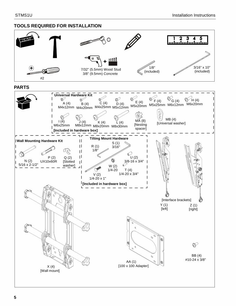
Installing to a Wood Stud Wall1. Determine the center of the TV screen, and where it should
be located on the wall.
2. Locate the stud at the selected location.
3. Line up the notches on wall mount (X) with center of screenmarking to determine vertical center. (See Figure 1)
4. Measure up 6" (152.4 mm) from the center point to marklocation of the upper mounting slots.
Figure 1
5. Mark the wall on the stud to attach the mount through theupper mounting slot. (See Figure 2)
6. Drill one 7/32" (5.5mm) pilot hole in stud.
7. Partially install one 5/16 x 2-1/2" flanged lag bolt (N) intopilot holes but do not tighten to wall.
8. Hang mount (X), aligning upper mounting slot over lag bolt.
9. Place one slotted washer (Q) over flanged lag bolt. (SeeFigure 2)
10. Tighten lag bolt to secure mount (X) to wall at uppermounting slot.
Figure 2
11. Mark the attachment points for the lower mounting slot,making sure the attachment point is located on the stud.(See Figure 2)
12. Drill 7/32" (5.5mm) pilot hole at marking for lower mountinghole. (See Figure 2)
13. Use one 5/16 x 2-1/2" flanged lag bolts (N) and one 5/16"slotted washers (Q) to attach the mount to the wall throughthe lower mounting hole. (See Figure 2)
14. Proceed to Locking Rails section.
Center of screen
6"
Vertical centerof mount
(152.4mm)
(X)
11 12
5 6
(Q)
710
(N)
(X)
9 (Q)
13 (N)
13
Installation Instructions STMS1U
7
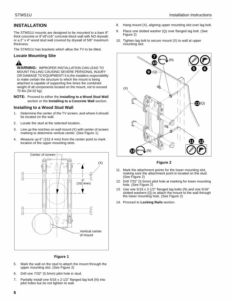
Installing to a Concrete Wall1. Determine the center of the TV screen, and where it should
be located on the wall.
2. Line up the notches on mount (X) with center of screenmarking to determine vertical center. (See Figure 1)
3. Measure up 6" (152.4mm) from the center point to marklocation of the upper mounting slot. (See Figure 1)
4. Mark the wall through upper mounting slot. (See Figure 3)
Figure 35. Drill one 3/8" x 3-1/2" (9.5mm x 88.9mm) pilot hole at each
marking.
6. Install one anchor (P) into pilot hole using a hammer,making sure that the anchor is flush with the wall.
7. Partially install one 5/16 x 2-1/2" flanged lag bolt (N) intopilot hole but do not tighten to wall.
8. Hang mount (X), aligning upper mounting slot over lag bolt.(See Figure 3)
9. Place one slotted washer (Q) over flanged lag bolt. (SeeFigure 3)
10. Tighten lag bolt to secure mount (X) to wall at uppermounting slots.
11. Mark the attachment point for the lower mounting slot. (SeeFigure 3)
12. Drill 3/8" x 3-1/2" (9.5mm x 88.9mm) pilot hole at marking forlower mounting hole. (See Figure 3)
13. Use one 5/16 x 2-1/2" flanged lag bolt (N) and one 5/16"slotted washer (Q) to attach the mount to the wall throughthe lower mounting hole. (See Figure 3)
14. Slide rails to approximate center of screen location.
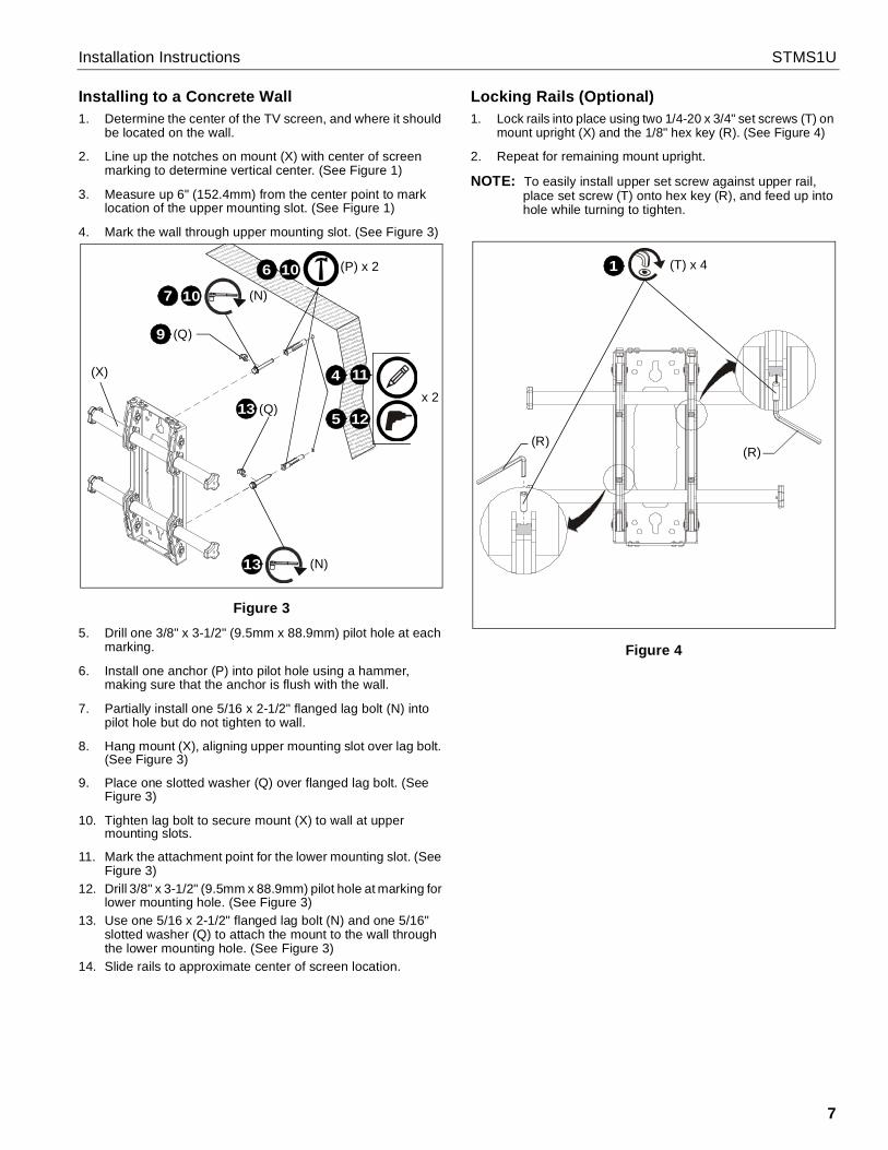
Locking Rails (Optional)1. Lock rails into place using two 1/4-20 x 3/4" set screws (T) on
mount upright (X) and the 1/8" hex key (R). (See Figure 4)
2. Repeat for remaining mount upright.
NOTE: To easily install upper set screw against upper rail,place set screw (T) onto hex key (R), and feed up intohole while turning to tighten.
Figure 4
11
5
6
4
12x 2
(P) x 210
7 10 (N)
(Q)9
(Q)13
13 (N)
(X)
(T) x 41
(R)(R)

STMS1U Installation Instructions
8
Attaching Interface Brackets to ScreenNOTE: For 100x100mm and 75x75mm hole patterns, the
100x100 adapter must be installed. For all other holepatterns, proceed ahead to step 2.
1. (100x100mm and 75x75mm hole patterns ONLY) Usefour #10-24 X 3/8" Phillips pan machine screws (BB) tosecure two interface brackets (Y and Z) to adapter bracket(AA). (See Figure 5)
Figure 5
2. Align the center of the bracket (Y and Z) with center ofscreen. (See Figure 6)
NOTE: The diamond-shape holes in the bracket correspond tothe center of the mount.
WARNING: IMPROPER INSTALLATION CAN LEAD TODISPLAY FALLING CAUSING SERIOUS PERSONALINJURY OR DAMAGE TO EQUIPMENT! Using screws ofimproper size may damage your display. Properly sizedscrews will easily and completely thread into displaymounting holes. If spacers are required, be sure to use longerscrews of the same diameter.
3. Select correct screws, nesting spacers (if necessary) anduniversal washers (if required) from the hardware bag (A-L)and attach brackets to back of screen. (See Figure 6)
Figure 6
IMPORTANT ! : The M8 screws do NOT require awasher. Use the universal washer (MB) only with M4, M5and M6 screws.
NOTE: The nesting spacers (MA) may be used separately, orput two together in different configurations to createdifferent size spacers. (See Figure 7)
Figure 7
(AA)
(Z)
(Y)
(BB) x 41
Center of bracketPull cord
(MA) (MB)
(A-L)
NOTE: Use universal washer (MB) ONLY with M4, M5 and M6 screws.
3
(without adapter)
(with adapter)
Pull cord
(A-L)3
(MA)
(MB)
(Single) (Nested) (Stacked)
0.375 [9.5]
0.563 [14.3]
0.750 [19.1]

Installation Instructions STMS1U
9
Attaching Screen to Wall MountNOTE: Interface brackets (Y and Z) cannot be installed inside
the two upright brackets of wall mount! Both interfacebracket must be installed to the outside of the uprightbrackets. (See Figure 8)
Figure 8
1. Hang screen onto the top rail of the mount (X). (See Figure9)• Move latch on top of interface brackets to OPEN
position and hang top hook of interface bracket (Y andZ) onto the top rail of the mount (X). (See Figure 9)
NOTE: The screen initially installs into the "service mode" toallow easy cable access.
2. Adjust screen and rails to desired viewing position.
3. Route cables between wall and rails.
CAUTION: PINCH POINTS! Keep fingers, hands andcables out of pinch point areas.
4. Pull downward on the pull cords and swing inward towardwall, latching interface brackets to lower rail and fasteningbottom of screen to the mount.
5. Attach end of pull cord (a magnet) to mount so it does notextend beyond bottom of screen. (See Figure 9)
Figure 9
Adjustments Roll/Height Adjustment of Wall Brackets
NOTE: The height adjust wall brackets allow adjustment of+ 1/2".
1. Turn to right (tighten) to raise side of screen. (See Figure 10)
2. Turn to left (loosen) to lower side of the screen.
Figure 10
Interface brackets cannot be installed insidethe two upright brackets of the wall mount!
[Brackets Y and Z shown]
upright brackets
Latch in
6 Pullcords
5
5
2
OPENposition
Raises screen
Lowers screen
1
2
(S)
(Screen not shown for clarity)

STMS1U Installation Instructions
10
Tilt
The interface brackets (Y and Z) allow from -2° to 12° tilt, andcan be locked at 0°, 6° and 12°.
1. Loosen the interface bracket knob.
2. Adjust tilt as required. (See Figure 11)
3. The tilt may be locked at 0°, 6° or 12° using one 1/4-20 x 1"round head carriage bolt (V) and one 1/4-20 hex nut (W) perinterface bracket. (See Figure 11)
4. Tighten interface bracket knob as necessary.
Figure 11
Locking Screen Interface Brackets (Optional)
1. Lock screen interface brackets onto mount rails using one3/8-16 x 3/4" set screw (U) on each interface bracket. (SeeFigure 12)
Figure 12
Locking Mount (Optional)
1. Add padlock (not included) to interface bracket to completesecurity. (See Figure 13)
NOTE: The padlock maximum shackle diameter is 5/16"(7.9 mm).
Figure 13
Latch inCLOSEDposition
3 (W)
(V)2
Lock at 12° tilt
Lock at 6° tilt
Lock at 0° tilt
Interfacebracketknob
1 (U) x 2
1
Padlock shackle
- 5/16" (7.9mm)maximum diameter:

Installation Instructions STMS1U
11

STMS1U Installation Instructions
USA/International A 6436 City West Parkway, Eden Prairie, MN 55344P 800.582.6480 / 952.225.6000F 877.894.6918 / 952.894.6918
Europe A Franklinstraat 14, 6003 DK Weert, NetherlandsP +31 (0) 495 580 852F +31 (0) 495 580 845
Asia Pacific A Office No. 918 on 9/F, Shatin Galleria18-24 Shan Mei StreetFotan, Shatin, Hong Kong
P 852 2145 4099F 852 2145 4477
Chief, a products division ofMilestone AV Technologies
8800-002881 Rev002016 Milestone AV Technologies
www.milestone.com9/16