STM3210E-EVAL evaluation board - st.com · DocID14220 Rev 6 9/50 UM0488 Hardware layout and...
50
August 2013 DocID14220 Rev 6 1/50 UM0488 User manual STM3210E-EVAL evaluation board Introduction The STM3210E-EVAL evaluation board is designed as a complete development platform for STMicroelectronic's ARM Cortex-M3 core-based STM32F103ZGT6 microcontroller with full speed USB2.0, CAN2.0A/B compliant interface, two I2S channels, two I2C channels, five USART channels with smartcard support, three SPI channels, two DAC channels, FSMC interface, SDIO, internal 96 KB SRAM and 1 MB Flash, JTAG and SWD debug support. The STM3210E-EVAL products delivered with the MB672 board versions D-03 or older are based on the STM32F103ZET6 instead of the STM32F103ZGT6 and include 64 KB internal SRAM and 512 KB Flash. The board number and version are on a label on the bottom side of the board. The full range of hardware features on the board helps you to evaluate all peripherals (USB, motor control, CAN, MicroSD Card, smartcard, USART, NOR Flash, NAND Flash, SRAM) and develop your own applications. Extension headers make it easy to connect a daughterboard or wrapping board for your specific application. Figure 1. STM3210E-EVAL evaluation board www.st.com
Transcript of STM3210E-EVAL evaluation board - st.com · DocID14220 Rev 6 9/50 UM0488 Hardware layout and...

August 2013 DocID14220 Rev 6 1/50
UM0488User manualSTM3210E-EVAL evaluation board
IntroductionThe STM3210E-EVAL evaluation board is designed as a complete development platform for STMicroelectronic's ARM Cortex-M3 core-based STM32F103ZGT6 microcontroller with full speed USB2.0, CAN2.0A/B compliant interface, two I2S channels, two I2C channels, five USART channels with smartcard support, three SPI channels, two DAC channels, FSMC interface, SDIO, internal 96 KB SRAM and 1 MB Flash, JTAG and SWD debug support.
The STM3210E-EVAL products delivered with the MB672 board versions D-03 or older are based on the STM32F103ZET6 instead of the STM32F103ZGT6 and include 64 KB internal SRAM and 512 KB Flash. The board number and version are on a label on the bottom side of the board.
The full range of hardware features on the board helps you to evaluate all peripherals (USB, motor control, CAN, MicroSD Card, smartcard, USART, NOR Flash, NAND Flash, SRAM) and develop your own applications. Extension headers make it easy to connect a daughterboard or wrapping board for your specific application.
Figure 1. STM3210E-EVAL evaluation board
www.st.com

Contents UM0488
2/50 DocID14220 Rev 6
Contents
1 Overview . . . . . . . . . . . . . . . . . . . . . . . . . . . . . . . . . . . . . . . . . . . . . . . . . . 61.1 Order code . . . . . . . . . . . . . . . . . . . . . . . . . . . . . . . . . . . . . . . . . . . . . . . . . 6
1.2 Features . . . . . . . . . . . . . . . . . . . . . . . . . . . . . . . . . . . . . . . . . . . . . . . . . . . 6
1.3 Demonstration software . . . . . . . . . . . . . . . . . . . . . . . . . . . . . . . . . . . . . . . 6
2 Hardware layout and configuration . . . . . . . . . . . . . . . . . . . . . . . . . . . . . 72.1 Power supply . . . . . . . . . . . . . . . . . . . . . . . . . . . . . . . . . . . . . . . . . . . . . . . 9
2.2 Boot option . . . . . . . . . . . . . . . . . . . . . . . . . . . . . . . . . . . . . . . . . . . . . . . . 10
2.3 Clock source . . . . . . . . . . . . . . . . . . . . . . . . . . . . . . . . . . . . . . . . . . . . . . . 10
2.4 Reset source . . . . . . . . . . . . . . . . . . . . . . . . . . . . . . . . . . . . . . . . . . . . . . 10
2.5 Audio . . . . . . . . . . . . . . . . . . . . . . . . . . . . . . . . . . . . . . . . . . . . . . . . . . . . .11
2.6 Serial Flash . . . . . . . . . . . . . . . . . . . . . . . . . . . . . . . . . . . . . . . . . . . . . . . .11
2.7 CAN . . . . . . . . . . . . . . . . . . . . . . . . . . . . . . . . . . . . . . . . . . . . . . . . . . . . . .11
2.8 RS-232 connectors . . . . . . . . . . . . . . . . . . . . . . . . . . . . . . . . . . . . . . . . . . 12
2.9 Motor control . . . . . . . . . . . . . . . . . . . . . . . . . . . . . . . . . . . . . . . . . . . . . . 12
2.10 Smartcard . . . . . . . . . . . . . . . . . . . . . . . . . . . . . . . . . . . . . . . . . . . . . . . . . 13
2.11 MicroSD Card . . . . . . . . . . . . . . . . . . . . . . . . . . . . . . . . . . . . . . . . . . . . . . 13
2.12 Temperature sensor . . . . . . . . . . . . . . . . . . . . . . . . . . . . . . . . . . . . . . . . . 14
2.13 Analog input . . . . . . . . . . . . . . . . . . . . . . . . . . . . . . . . . . . . . . . . . . . . . . . 14
2.14 IrDA . . . . . . . . . . . . . . . . . . . . . . . . . . . . . . . . . . . . . . . . . . . . . . . . . . . . . 14
2.15 USB . . . . . . . . . . . . . . . . . . . . . . . . . . . . . . . . . . . . . . . . . . . . . . . . . . . . . 14
2.16 Development and debug support . . . . . . . . . . . . . . . . . . . . . . . . . . . . . . . 15
2.17 Display and input devices . . . . . . . . . . . . . . . . . . . . . . . . . . . . . . . . . . . . . 15
2.18 SRAM . . . . . . . . . . . . . . . . . . . . . . . . . . . . . . . . . . . . . . . . . . . . . . . . . . . . 16
2.19 NAND Flash . . . . . . . . . . . . . . . . . . . . . . . . . . . . . . . . . . . . . . . . . . . . . . . 16
2.20 NOR Flash . . . . . . . . . . . . . . . . . . . . . . . . . . . . . . . . . . . . . . . . . . . . . . . . 17
3 Connectors . . . . . . . . . . . . . . . . . . . . . . . . . . . . . . . . . . . . . . . . . . . . . . . 183.1 Motor control connector CN1 . . . . . . . . . . . . . . . . . . . . . . . . . . . . . . . . . . 18
3.2 Analog input connectors CN2, CN3 and CN5 . . . . . . . . . . . . . . . . . . . . . 19
3.3 CAN D-type 9-pin male connector CN4 . . . . . . . . . . . . . . . . . . . . . . . . . . 19

DocID14220 Rev 6 3/50
UM0488 Contents
3
3.4 QST connector CN6 . . . . . . . . . . . . . . . . . . . . . . . . . . . . . . . . . . . . . . . . . 19
3.5 Trace debugging connector CN7 . . . . . . . . . . . . . . . . . . . . . . . . . . . . . . . 20
3.6 RS-232 connector CN8 with RTS/CTS handshake support . . . . . . . . . . . 21
3.7 JTAG debugging connector CN9 . . . . . . . . . . . . . . . . . . . . . . . . . . . . . . . 21
3.8 Daughterboard extension connectors CN10 and CN11 . . . . . . . . . . . . . . 22
3.9 RS-232 connector CN12 . . . . . . . . . . . . . . . . . . . . . . . . . . . . . . . . . . . . . 28
3.10 MicroSD Card connector CN13 . . . . . . . . . . . . . . . . . . . . . . . . . . . . . . . . 28
3.11 USB type B connector CN14 . . . . . . . . . . . . . . . . . . . . . . . . . . . . . . . . . . 29
3.12 Audio jack CN15 . . . . . . . . . . . . . . . . . . . . . . . . . . . . . . . . . . . . . . . . . . . . 29
3.13 TFT LCD connector CN16 . . . . . . . . . . . . . . . . . . . . . . . . . . . . . . . . . . . . 29
3.14 Power connector CN17 . . . . . . . . . . . . . . . . . . . . . . . . . . . . . . . . . . . . . . 29
3.15 Smartcard connector CN18 . . . . . . . . . . . . . . . . . . . . . . . . . . . . . . . . . . . 30
4 Schematic diagrams . . . . . . . . . . . . . . . . . . . . . . . . . . . . . . . . . . . . . . . . 31
Appendix A STM3210E-EVAL I/O assignment . . . . . . . . . . . . . . . . . . . . . . . . . . . 44
Revision history . . . . . . . . . . . . . . . . . . . . . . . . . . . . . . . . . . . . . . . . . . . . . . . . . . . . 49

List of tables UM0488
4/10 DocID14220 Rev 6
List of tables
Table 1. Power related jumpers . . . . . . . . . . . . . . . . . . . . . . . . . . . . . . . . . . . . . . . . . . . . . . . . . . . . . 9Table 2. Boot related switches . . . . . . . . . . . . . . . . . . . . . . . . . . . . . . . . . . . . . . . . . . . . . . . . . . . . . 10Table 3. Reset related jumper . . . . . . . . . . . . . . . . . . . . . . . . . . . . . . . . . . . . . . . . . . . . . . . . . . . . . 10Table 4. Audio related jumpers. . . . . . . . . . . . . . . . . . . . . . . . . . . . . . . . . . . . . . . . . . . . . . . . . . . . . 11Table 5. CAN related jumpers . . . . . . . . . . . . . . . . . . . . . . . . . . . . . . . . . . . . . . . . . . . . . . . . . . . . . 11Table 6. Motor control related jumpers . . . . . . . . . . . . . . . . . . . . . . . . . . . . . . . . . . . . . . . . . . . . . . . 12Table 7. Connection between ST8024 and STM32F103ZGT6 . . . . . . . . . . . . . . . . . . . . . . . . . . . . 13Table 8. Smartcard related jumpers . . . . . . . . . . . . . . . . . . . . . . . . . . . . . . . . . . . . . . . . . . . . . . . . . 13Table 9. MicroSD Card related jumpers . . . . . . . . . . . . . . . . . . . . . . . . . . . . . . . . . . . . . . . . . . . . . . 14Table 10. IrDA related jumpers. . . . . . . . . . . . . . . . . . . . . . . . . . . . . . . . . . . . . . . . . . . . . . . . . . . . . . 14Table 11. USB related jumpers. . . . . . . . . . . . . . . . . . . . . . . . . . . . . . . . . . . . . . . . . . . . . . . . . . . . . . 15Table 12. LCD modules . . . . . . . . . . . . . . . . . . . . . . . . . . . . . . . . . . . . . . . . . . . . . . . . . . . . . . . . . . . 15Table 13. NAND Flash related jumpers . . . . . . . . . . . . . . . . . . . . . . . . . . . . . . . . . . . . . . . . . . . . . . . 17Table 14. NOR Flash related jumpers . . . . . . . . . . . . . . . . . . . . . . . . . . . . . . . . . . . . . . . . . . . . . . . . 17Table 15. NOR Flash reference . . . . . . . . . . . . . . . . . . . . . . . . . . . . . . . . . . . . . . . . . . . . . . . . . . . . . 17Table 16. Motor control connector CN1 . . . . . . . . . . . . . . . . . . . . . . . . . . . . . . . . . . . . . . . . . . . . . . . 18Table 17. Analog input connector CN2, CN3 and CN5 . . . . . . . . . . . . . . . . . . . . . . . . . . . . . . . . . . . 19Table 18. CAN D-type 9-pins male connector CN4 . . . . . . . . . . . . . . . . . . . . . . . . . . . . . . . . . . . . . . 19Table 19. QST connector CN6 . . . . . . . . . . . . . . . . . . . . . . . . . . . . . . . . . . . . . . . . . . . . . . . . . . . . . . 20Table 20. Trace debugging connector CN7 . . . . . . . . . . . . . . . . . . . . . . . . . . . . . . . . . . . . . . . . . . . . 20Table 21. RS-232 connector CN8 with RTS/CTS handshake support . . . . . . . . . . . . . . . . . . . . . . . . 21Table 22. JTAG debugging connector CN9 . . . . . . . . . . . . . . . . . . . . . . . . . . . . . . . . . . . . . . . . . . . . 21Table 23. Daughterboard extension connector CN10 . . . . . . . . . . . . . . . . . . . . . . . . . . . . . . . . . . . . 22Table 24. Daughterboard extension connector CN11 . . . . . . . . . . . . . . . . . . . . . . . . . . . . . . . . . . . . 25Table 25. RS-232 connector CN12. . . . . . . . . . . . . . . . . . . . . . . . . . . . . . . . . . . . . . . . . . . . . . . . . . . 28Table 26. MicroSD Card connector CN13 . . . . . . . . . . . . . . . . . . . . . . . . . . . . . . . . . . . . . . . . . . . . . 28Table 27. USB type B connector CN14 . . . . . . . . . . . . . . . . . . . . . . . . . . . . . . . . . . . . . . . . . . . . . . . 29Table 28. Smartcard connector CN18 . . . . . . . . . . . . . . . . . . . . . . . . . . . . . . . . . . . . . . . . . . . . . . . . 30Table 29. STM3210E-EVAL I/O assignment . . . . . . . . . . . . . . . . . . . . . . . . . . . . . . . . . . . . . . . . . . . 44Table 30. Document revision history . . . . . . . . . . . . . . . . . . . . . . . . . . . . . . . . . . . . . . . . . . . . . . . . . 49

DocID14220 Rev 6 5/50
UM0488 List of figures
5
List of figures
Figure 1. STM3210E-EVAL evaluation board . . . . . . . . . . . . . . . . . . . . . . . . . . . . . . . . . . . . . . . . . . . 1Figure 2. Hardware block diagram. . . . . . . . . . . . . . . . . . . . . . . . . . . . . . . . . . . . . . . . . . . . . . . . . . . . 7Figure 3. STM3210E-EVAL evaluation board layout . . . . . . . . . . . . . . . . . . . . . . . . . . . . . . . . . . . . . . 8Figure 4. Motor control connector CN1 (top view) . . . . . . . . . . . . . . . . . . . . . . . . . . . . . . . . . . . . . . . 18Figure 5. Analog input connector CN2, CN3 and CN5 bottom view . . . . . . . . . . . . . . . . . . . . . . . . . 19Figure 6. CAN D-type 9-pin male connector CN4 (front view) . . . . . . . . . . . . . . . . . . . . . . . . . . . . . . 19Figure 7. QST connector CN6 (front view). . . . . . . . . . . . . . . . . . . . . . . . . . . . . . . . . . . . . . . . . . . . . 19Figure 8. Trace debugging connector CN7 (top view) . . . . . . . . . . . . . . . . . . . . . . . . . . . . . . . . . . . . 20Figure 9. RS-232 connector CN8 with RTS/CTS handshake support (front view). . . . . . . . . . . . . . . 21Figure 10. JTAG debugging connector CN9 (top view) . . . . . . . . . . . . . . . . . . . . . . . . . . . . . . . . . . . . 21Figure 11. RS-232 connector CN12 (front view) . . . . . . . . . . . . . . . . . . . . . . . . . . . . . . . . . . . . . . . . . 28Figure 12. MicroSD Card connector CN13 (front view) . . . . . . . . . . . . . . . . . . . . . . . . . . . . . . . . . . . . 28Figure 13. USB type B connector CN14 (top view) . . . . . . . . . . . . . . . . . . . . . . . . . . . . . . . . . . . . . . . 29Figure 14. Power supply connector CN17 (front view) . . . . . . . . . . . . . . . . . . . . . . . . . . . . . . . . . . . . 29Figure 15. Smartcard connector CN18 (front view) . . . . . . . . . . . . . . . . . . . . . . . . . . . . . . . . . . . . . . . 30Figure 16. Microcontroller . . . . . . . . . . . . . . . . . . . . . . . . . . . . . . . . . . . . . . . . . . . . . . . . . . . . . . . . . . 32Figure 17. MCU . . . . . . . . . . . . . . . . . . . . . . . . . . . . . . . . . . . . . . . . . . . . . . . . . . . . . . . . . . . . . . . . . . 33Figure 18. Peripherals . . . . . . . . . . . . . . . . . . . . . . . . . . . . . . . . . . . . . . . . . . . . . . . . . . . . . . . . . . . . . 34Figure 19. RS-232 and IrDA . . . . . . . . . . . . . . . . . . . . . . . . . . . . . . . . . . . . . . . . . . . . . . . . . . . . . . . . 35Figure 20. Audio. . . . . . . . . . . . . . . . . . . . . . . . . . . . . . . . . . . . . . . . . . . . . . . . . . . . . . . . . . . . . . . . . . 36Figure 21. LCD and joystick. . . . . . . . . . . . . . . . . . . . . . . . . . . . . . . . . . . . . . . . . . . . . . . . . . . . . . . . . 37Figure 22. SD Card and smartcard . . . . . . . . . . . . . . . . . . . . . . . . . . . . . . . . . . . . . . . . . . . . . . . . . . . 38Figure 23. Motor control . . . . . . . . . . . . . . . . . . . . . . . . . . . . . . . . . . . . . . . . . . . . . . . . . . . . . . . . . . . . 39Figure 24. JTAG and trace connectors . . . . . . . . . . . . . . . . . . . . . . . . . . . . . . . . . . . . . . . . . . . . . . . . 40Figure 25. Power supply . . . . . . . . . . . . . . . . . . . . . . . . . . . . . . . . . . . . . . . . . . . . . . . . . . . . . . . . . . . 41Figure 26. SRAM and Flash. . . . . . . . . . . . . . . . . . . . . . . . . . . . . . . . . . . . . . . . . . . . . . . . . . . . . . . . . 42Figure 27. Color LCD module . . . . . . . . . . . . . . . . . . . . . . . . . . . . . . . . . . . . . . . . . . . . . . . . . . . . . . . 43

Overview UM0488
6/50 DocID14220 Rev 6
1 Overview
1.1 Order codeTo order the STM32F103ZGT6GT6 evaluation board, use the order code STM3210E-EVAL.
1.2 Features• Three 5 V power supply options: power jack, USB connector or daughterboard• Boot from user Flash, system memory or SRAM• I2S audio DAC, stereo audio jack• 128 Mbyte MicroSD CardTM
• Both A and B type smartcard support• 64 or 128 Mbit serial Flash, 512 Kx16 SRAM, 512 Mbit or 1 Gbit NAND Flash and 128
Mbit NOR Flash• I2C/SMBus compatible serial interface temperature sensor• Two RS-232 channels with RTS/CTS handshake support on one channel• IrDA transceiver• USB2.0 full speed connection• CAN2.0A/B compliant connection• Inductor motor control connector• JTAG and trace debug support• 240x320 TFT color LCD• Joystick with 4-direction control and selector• Reset, wakeup, tamper and user buttons• 4 color LEDs• RTC with backup battery
1.3 Demonstration softwareDemonstration software is preloaded in board’s Flash memory for easy demonstration of the device peripherals in stand-alone mode. For more information and to download the latest version available, please refer to the STM3210E-EVAL demonstration software available from www.st.com
To use the STM3210E-EVAL evaluation board, you must have the demonstration software version 1.1 or later. If the version installed on your evaluation board is earlier than version 1.1, you must download the latest version from www.st.com.

DocID14220 Rev 6 7/50
UM0488 Hardware layout and configuration
49
2 Hardware layout and configuration
The STM3210E-EVAL evaluation board is designed around the STM32F103ZGT6 microcontroller in a 144-pin TQFP package. The hardware block diagram Figure 2 illustrates the connections between the STM32F103ZGT6 and peripherals (LCD, SPI Flash, USART, IrDA, USB, audio, CAN bus, smartcard, MicroSD Card, NOR Flash, NAND Flash, SRAM, temperature sensor, audio DAC and motor control) and Figure 3 helps you to locate these features on the actual evaluation board.
Figure 2. Hardware block diagram
MS30067V1
STM32103Z
Audio DACI2S
GPIO
RS-232 transceiver
QST connector
Extension connector for GPIOs
USART 1 DB9 connector
RS-232 transceiver
USART 2 DB9 connector
IrDA transceiver
USART 1 DB9 connector
SmartCard interface
SmartCard connector
CAN transceiver
CAN DB9 connector
3 BNC connectors
Potentiometer
USB type B connector
USART 1
USART 2
USART 4
USART 3
CAN
ADC
USB
Trace
JTAG
Temperature sensor
MicroSD card
MC controlconnector
64 Mbit / 128 Mbit serial Flash
SDIO
I2C
Debug
MC
SPI1
FSMC
3.3 V regulator
512 K x 16 SRAM
1 Gbit NAND
128 Mbit NOR
TFT LCD

Hardware layout and configuration UM0488
8/50 DocID14220 Rev 6
Figure 3. STM3210E-EVAL evaluation board layout
CN10Extension connector
CN8
U1STM32F103ZG
CN2,3,5
U13
CN14
CN12
B1RESET
B2WAKEUP
CN18Smartcard
B3Tamper
U19Joystick
B4User key
CN1
CN4CAN connector
CN6QST
CN7Trace
CN9JTAG
U17Color LCD
CN15Audio jack
RV1Potentiometer
CN11Extension connector
CN13MicroSD
CN17

DocID14220 Rev 6 9/50
UM0488 Hardware layout and configuration
49
2.1 Power supplyThe STM3210E-EVAL evaluation board is designed to be powered by 5V DC power supply and to be protected by PolyZen U15 in the event of wrong power plug-in. It is possible to configure the evaluation board to use any of following three sources for the power supply:• 5V DC power adapter connected to CN17, the power jack on the board (PSU on silk
screen for power supply unit).• 5V DC power with 500 mA limitation from CN14, the type-B USB connector (USB on
silkscreen).• 5V DC power from both CN10 and CN11, the extension connector for daughterboard
(DTB for daughterboard on silkscreen).
The power supply is configured by setting the related jumpers JP13, JP12 and JP1 as described in Table 1. The LED LD5 is lit when the STM3210E-EVAL evaluation board is powered correctly.
Table 1. Power related jumpersJumper Description
JP13
JP13 is used to select one of the three possible power supply resources.For power supply jack(CN17) to the STM3210E-EVAL only, JP13 is set as shown (default setting).
For power supply from the daughterboard connectors(CN10 and CN11) to STM3210E-EVAL only, JP13 is set as shown.
For power supply from USB (CN14) to STM3210E-EVAL only, JP13 is set as shown.
For power supply from power supply jack(CN17) to both STM3210E-EVAL and daughterboard connected on CN10 and CN11, JP13 is set as shown (daughterboard must not have its own power supply connected).
JP12Enables consumption measurements of both VDD and VDDA.Default setting: Fitted
JP1
Vbat is connected to 3.3V power when JP1 is set as shown (default setting).
Vbat is connected to battery when JP1 is set as shown.
PSU
DTB
U
SB
PS
U
DTB
U
SB
PSU
D
TB
US
B
PSU
DTB
USB
1 2 3
1 2 3

Hardware layout and configuration UM0488
10/50 DocID14220 Rev 6
2.2 Boot optionThe STM3210E-EVAL evaluation board can boot from:• Embedded user Flash• System memory with boot loader for ISP• Embedded SRAM for debugging
The boot option is configured by setting the switches BOOT0 and BOOT1.
2.3 Clock sourceTwo clock sources are available on the STM3210E-EVAL evaluation board for STM32F103 and RTC.• X2, 32KHz crystal for embedded RTC.• X1, 8MHz crystal with socket for STM32F103ZGT6 microcontroller, it can be removed
from socket when internal RC clock is used.
2.4 Reset sourceThe reset signal of the STM3210E-EVAL evaluation board is low active and the reset sources include:• Reset button B1• Debugging tools from JTAG connector CN7 and trace connector CN9• Daughterboard from CN11
Table 2. Boot related switches
Switch Boot from Switch configuration
BOOT0BOOT1
STM3210E-EVAL boots from User Flash when BOOT0 is set as shown to the right. BOOT1 is not required in this configuration.(Default setting)
STM3210E-EVAL boot from Embedded SRAM when BOOT0 and BOOT1 are set as shown to the right.
STM3210E-EVAL boot from System Memory when BOOT0 and BOOT1 are set as shown to the right.
0 < > 1
Boot 0
0 < > 1
Boot 0
Boot 1
0 < > 1
Boot 0
Boot 1
Table 3. Reset related jumperJumper Description
JP19Enables reset of the STM32F103ZGT6 embedded JTAG TAP controller each time a system reset occurs. JP19 connects the TRST signal from the JTAG connection with the system reset signal RESET#. Default setting: not fitted

DocID14220 Rev 6 11/50
UM0488 Hardware layout and configuration
49
2.5 AudioThe STM3210E-EVAL evaluation board supports stereo audio play because it provides an audio DAC AK4343 connected to both I2S port and two channels of DAC of microcontroller STM32F103ZGT6. Either external slave mode or PLL slave mode (reference clock BICK or LRCK) of audio DAC can be used by setting the jumper JP18.
The I2S_MCK is multiplexed with smartcard and motor control, and can be enabled by setting the jumper JP15. Refer to Section 2.9: Motor control for details. Audio DAC AK4343 is in power-down mode when PDN pin is pulled-down by PG11.
2.6 Serial FlashA 64 or 128 Mbit serial Flash connected to SPI1 of STM32F103ZGT6 serial Flash chip select is managed by IO-pin PB2. The SPI1_MISO is multiplexed with motor control, it can be enabled by setting the jumper JP3. Refer to Section 2.9: Motor control for details.
2.7 CANThe STM3210E-EVAL evaluation board supports CAN2.0A/B compliant CAN bus communication based on 3.3 V CAN transceiver. High-speed mode, standby mode and slope control mode are available and can be selected by setting JP8.
Table 4. Audio related jumpersJumper Description
JP18
External slave mode (MCK from STM32F103ZGT6) is selected when JP18 is set as shown (default setting).
PLL slave mode (reference clock BICK or LRCK) is selected when JP18 is set as shown.
1 2 3
1 2 3
Table 5. CAN related jumpersJumper Description
JP8
CAN transceiver works in standby mode when JP8 is set as shown.
CAN transceiver works in high-speed mode when JP8 is set as shown (default setting).
CAN transceiver works in slope control mode when JP8 is open.
JP6CAN terminal resistor is enabled when JP6 is fitted.Default setting: not fitted
1 2 3
1 2 3

Hardware layout and configuration UM0488
12/50 DocID14220 Rev 6
2.8 RS-232 connectorsTwo D-type 9-pin connectors CN12 (USART1) and CN8 (USART2) are available on the STM3210E-EVAL evaluation board.• USART1 connector is connected to RS-232 transceiver U7 .• USART2 connector with RTS/CTS handshake signal support is connected to RS-232
transceiver U5. The USART2_CTS is multiplexed with motor control, it can be enabled by setting jumper JP4. Refer to Section 2.9: Motor control for details.
2.9 Motor controlThe STM3210E-EVAL evaluation board supports three-phase brushless motor control via a 34-pin connector CN1, which provides all required control and feedback signals to and from the motor power driving board. Available signals on this connector include emergency stop, motor speed, three-phase motor current, bus voltage, heatsink temperature from the motor driving board and 6 channels of PWM control signals going to the motor driving circuit.
JP 20 selects one of the two synchronization methods for power factor correction (PFC).
The I/O pins used on the motor control connector CN1 are multiplexed with some peripherals on the board; either the motor control connector or multiplexed peripherals can be enabled by setting the jumpers JP3, JP4, JP11, JP15 and JP16 as described in Table 6.
Table 6. Motor control related jumpers
Jumper Description Multiplexed peripherals
JP20JP20 allows to have a PFC synchronization signal redirected to the timer 3 input capture 1 pin, and additionally to the timer 3 external trigger input. JTAG debugging is disabled when JP20 is fitted. Default setting: not fitted
JP2JP2 should be kept on open when encoder signal is input from pin 31 of CN1 while it should be kept on close when analog signal is from pin 31 of CN1 for special motor. Default setting: not fitted
JP4
MC_EnA is enabled when JP4 is set as shown to the right (default setting):USART2_CTS is enabled when JP4 is set as show to the right:
USART2
JP3 MC_EmergencySTOP is enabled when JP3 is closed. The pin PA6 is used as SPI1_MISO when JP3 is open. Default setting: not fitted SPI1
JP11 MC_PFCpwm is enabled when JP11 is open. The pin PB5 will be used as interrupt input from temperature sensor when JP11 is closed.
Temperature sensor
JP15 MC_UH or I2S_MCK are enabled when JP15 is open. The pin PC6 is used as Smartcard_CMDVCC when JP15 is closed.
I2S and smartcard
JP16 MC_VH is enabled when JP16 is open. The pin PC7 is used as Smartcard_OFF when JP16 is closed Smartcard
1 2 3
1 2 3

DocID14220 Rev 6 13/50
UM0488 Hardware layout and configuration
49
2.10 SmartcardSTMicroelectronics smartcard interface chip ST8024 is used on the STM3210E-EVAL board for asynchronous 3 V and 5 V smartcards. It performs all supply protection and control functions based on the connections with STM32F103ZGT6 listed in Table 7. The Smartcard_CMDVCC and Smartcard_OFF are multiplexed with motor control. They can be enabled by setting the jumpers JP15 and JP16. Refer to Section 2.9: Motor control on page 12 for details.
2.11 MicroSD CardThe 128 Mbyte MicroSD Card connected to SDIO of STM32F103ZGT6 is available on the board. MicroSD Card detection is managed by standard IO port PF11. The MicroSD Card_D3 is multiplexed with IrDA. It can be enabled by setting the jumper JP22, as explained in Section 2.14: IrDA on page 14.The MicroSD Card_D0 and MicroSD Card CMD are multiplexed with the motor control connector. They can be enabled by setting the jumpers JP17 and JP20.
Table 7. Connection between ST8024 and STM32F103ZGT6
ST8024 signals Description Connect to STM32F10X
5V/3V Smartcard power supply selection pin PB0
I/OUC MCU data I/O line PB10
XTAL1 Crystal or external clock input PB12
OFF Detect presence of a card, interrupt to MCU, share same pin with motor controller PC7
RSTIN Card reset input from MCU PB11
CMDVCC Start activation sequence input (active low), share same pin with I2S DAC and motor control PC6
Table 8. Smartcard related jumpersJumper Description
JP15The CMDVCC is connected to PC6 when JP15 is closed. It should be kept on open, or the SD Card needs to be removed from the MicroSD Card connector when PC6 is used by I2S or motor control connector. Default setting: not fitted
JP16 The OFF is connected to PC7 when JP16 is closed. It has to be kept on open when PC7 is used by the motor control connector. Default setting: not fitted

Hardware layout and configuration UM0488
14/50 DocID14220 Rev 6
2.12 Temperature sensorOne I2C interface temperature sensor STLM75 (–55°C to +125°C) connected to I2C of STM32F103ZGT6 is available on the board.
2.13 Analog inputThree BNC connectors CN2,CN3 and CN5 are connected to PC3, PC2 and PC1 of the STM32F103ZGT6 as external analog input. The 50 ohm terminal resistor can be enabled by closing the solder bridge JP23, JP24 and JP25 for each BNC connector. A low-pass filter can be implemented for each BNC connector CN5, CN3 and CN2 by replacing R5 and C22, R4 and C13, R3 and C9 with the right resistor and capacitor values, depending on the requirements of your application.
2.14 IrDAIrDA communication is supported by the IrDA transceiver U13 connected to USART3 of STM32F103ZGT6. The IrDA transceiver can be enabled or disabled by JP21.
2.15 USBThe STM3210E-EVAL evaluation board supports USB2.0 compliant full speed communication via a USB type B connector (CN14). The evaluation board can be powered by this USB connection at 5 V DC with a 500 mA current limitation. USB disconnection simulation can be implemented by disconnecting the 1.5 K pull-up resistor from USB+ line. The USB disconnection simulation feature is enabled by setting JP14.
Table 9. MicroSD Card related jumpersJumper Description
JP17JP17 is used to enable MicroSD Card data line D0. MicroSD Card D0 is enabled when JP17 is fitted. The JP17 should be kept on open when motor control connector CN1 is used. Default setting: fitted
JP20JP20 is used by the motor control connector, refer to Table 6 for details. JP20 should be kept on open for MicroSD Card operation. JTAG debugging is disabled when JP20 is fitted.
Table 10. IrDA related jumpersJumper Description
JP21Enables/disables the IrDA transceiver. IrDA is enabled when JP21 is fitted (default setting).IrDA is disabled when JP21 is not fitted.
JP22IrDA_RX is enabled when JP22 is closed.I/O pin PC11 is data line 3 of the MicroSD Card when JP22 is open (default setting).

DocID14220 Rev 6 15/50
UM0488 Hardware layout and configuration
49
2.16 Development and debug supportThe two debug connectors available on the STM3210E-EVAL evaluation board are:• CN9: standard 20-pin JTAG interface connector, compliant with ARM7/9 debug tools.• CN7: SAMTEC 20-pin connector FTSH-110-01-L-DV for both SWD and Trace,
compliant with ARM CoreSight debug tools.
2.17 Display and input devicesThe 240x320 TFT color LCD connected to bank1 NOR/PSRAM4 of FSMC interface of the STM32F103ZGT6 and four general purpose color LEDs (LD 1,2,3,4) are available as display devices. A 4-direction joystick with selection key, general purpose button (B4), wakeup button (B2) and tamper detection button (B3) are available as input devices. The jumper JP4 should be kept open to enable the wakeup button B2 which shares the same I/O with USART2 and motor control connector.
The STM3210E-EVAL evaluation board also supports a second optional 122x32 graphic LCD that can be mounted on the U18 connector. By default, the graphic LCD is not present.
Table 11. USB related jumpersJumper Description
JP14
The USB 1.5K pull-up resistor is always connected to USB+ line when JP14 is set as shown.
The USB 1.5K pull-up resistor can be disconnected by software from USB+ line when JP14 is set as shown. In this case, the USB connect/disconnect feature is managed by standard IO port PB14 (default setting).
1 2 3
1 2 3
Table 12. LCD modules TFT LCD CN16 (default) Graphic LCD U18 (optional)
Pin on CN16 Description Pin connection Pin on
U18 Description Pin connection
1 CS CS of Bank3 of FSMC 1 Vss GND
2 RS FSMC_A0 2 Vcc 3.3V
3 WR/SCL FSMC_NWE 3 VO -
4 RD FSMC_NOE 4 CLK PA5
5 RESET RESET# 5 SID PA7
6 PD1 FSMC_D0 6 CS PF10
7 PD2 FSMC_D1 7 A +5V
8 PD3 FSMC_D2 8 K GND
9 PD4 FSMC_D3

Hardware layout and configuration UM0488
16/50 DocID14220 Rev 6
2.18 SRAM512Kx16 SRAM is connected to bank1 NOR/PSRAM3 of the FSMC interface and both 8-bit and 16-bit access are allowed by BLN0 and BLN1 connected to BLE and BHE of SRAM respectively.
2.19 NAND FlashThe 512 Mbit x8 or 1 Gbit x8 NAND Flash is connected to bank2 of the FSMC interface. The ready/busy signal can be connected to either WAIT signal or FSMC_INT2 signal of the STM32F103ZGT6 depending on the setting of JP7.
10 PD5 FSMC_D4
11 PD6 FSMC_D5
12 PD7 FSMC_D6
13 PD8 FSMC_D7
14 PD10 FSMC_D8
15 PD11 FSMC_D9
16 PD12 FSMC_D10
17 PD13 FSMC_D11
18 PD14 FSMC_D12
19 PD15 FSMC_D13
20 PD16 FSMC_D14
21 PD17 FSMC_D15
22 BL_GND GND
23 BL_control 3.3V
24 VDD 3.3V
25 VCI 3.3V
26 GND GND
27 GND GND
28 BL_VDD 3.3V
29 SDO PA6 via JP26
30 SDI PA7 via JP27
Table 12. LCD modules (continued)TFT LCD CN16 (default) Graphic LCD U18 (optional)
Pin on CN16 Description Pin connection Pin on
U18 Description Pin connection

DocID14220 Rev 6 17/50
UM0488 Hardware layout and configuration
49
2.20 NOR Flash128 Mbit NOR Flash is connected to bank1 NOR/PSRAM2 of the FSMC interface. The 16-bit operation mode is selected by a pull-up resistor connected to the BYTE pin of the NOR Flash. Write protection can be enabled or disabled by jumper JP5.
Three different NOR 128-Mbit references can be present on the evaluation board depending on component availability.
These three references are not identical in terms of ID code, speed, timing or block protection. The demonstration firmware and the software library delivered with the board support these three NOR Flash references. However, during the development of your application software, you must verify which NOR reference is implemented on your board (component referenced as U2 on silkscreen and schematic), and take its characteristics into account.
Table 13. NAND Flash related jumpersJumper Description
JP7
The ready/busy signal is connected to WAIT signal when JP7 is set as shown (default setting)
The ready/busy signal is connected to FSMC_INT2 signal when JP7 is set as shown.
1 2 3
1 2 3
Table 14. NOR Flash related jumpersJumper Description
JP5Write protection is enabled when JP5 is fitted.Write protection is disabled when JP5 is not fitted (default setting).
Table 15. NOR Flash referenceReference Manufacturer
M29W128GL70ZA6E NUMONYX
M29W128GH70ZA6E NUMONYX
S29GL128P90FFIR20 SPANSION

Connectors UM0488
18/50 DocID14220 Rev 6
3 Connectors
3.1 Motor control connector CN1
Figure 4. Motor control connector CN1 (top view)
Table 16. Motor control connector CN1
Description STM32F103ZGT6 pin
CN1 pin #
CN1 pin #
STM32F103ZGT6 pin Description
Emergency stop PA6 1 2 GND
PWM-UH PC6 3 4 GND
PWM-UL PA7 5 6 GND
PWM-VH PC7 7 8 GND
PWM-VL PB0 9 10 GND
PWM-WH PC8 11 12 GND
PWM-WL PB1 13 14 PC0 Bus voltage
Phase A current PC1 15 16 GND
Phase B current PC2 17 18 GND
Phase C current PC3 19 20 GND
NTC bypass relay PB12 21 22 GND
Dissipative brake PWMPA3 through
0 ohm resister unfitted
23 24 GND
+5V power +5V 25 26 PC5 Heatsink temperature
PFC SYNC PB4 and PD2 27 28 3.3V power
PFC PWM PB5 29 30 GND
Encoder A PA0 31 32 GND
Encoder B PA1 33 34 PA2 Encoder index
MS32821V1

DocID14220 Rev 6 19/50
UM0488 Connectors
49
3.2 Analog input connectors CN2, CN3 and CN5
Figure 5. Analog input connector CN2, CN3 and CN5 bottom view
3.3 CAN D-type 9-pin male connector CN4
Figure 6. CAN D-type 9-pin male connector CN4 (front view)
3.4 QST connector CN6The QST connector connects the STM3210E-EVAL to the QST evaluation board to demonstrate the QST function.
Figure 7. QST connector CN6 (front view)
Table 17. Analog input connector CN2, CN3 and CN5Pin number Description Pin number Description
1 GND 4 GND
2 GND5 Analog input PC3, PC2 and PC1
for CN2,CN3 and CN5 respectively3 GND
MS32822V1
Table 18. CAN D-type 9-pins male connector CN4Pin number Description Pin number Description
1,4,8,9 NC 7 CANH
2 CANL 3,5,6 GND
MS32823V1
MS32860V1
13 11 9 7 5 3 1
14 12 10 8 6 4 2

Connectors UM0488
20/50 DocID14220 Rev 6
3.5 Trace debugging connector CN7
Figure 8. Trace debugging connector CN7 (top view)
Table 19. QST connector CN6Pin number Description Pin number Description
1 +5V 2 +5V
3 PB6 4 PA5
5 PB7 6 PA7
7 PB1 8 PA6
9 PF11 10 PB5
11 PA8 12 -
13 GND 14 GND
Table 20. Trace debugging connector CN7Pin number Description Pin number Description
1 3.3V power 2 TMS/PA13
3 GND 4 TCK/PA14
5 GND 6 TDO/PB3
7 KEY 8 TDI/PA15
9 GND 10 RESET#
11 GND 12 TraceCLK/PE2
13 GND 14 TraceD0/PE3 or SWO/PB3
15 GND 16 TraceD1/PE4 or nTRST/PB4
17 GND 18 TraceD2/PE5
19 GND 20 TraceD3/PE6
MS32816V1
19 17 15 13 11 9 7 5 3 1
18 16 14 12 1020 8 6 4 2

DocID14220 Rev 6 21/50
UM0488 Connectors
49
3.6 RS-232 connector CN8 with RTS/CTS handshake support
Figure 9. RS-232 connector CN8 with RTS/CTS handshake support (front view)
3.7 JTAG debugging connector CN9
Figure 10. JTAG debugging connector CN9 (top view)
Table 21. RS-232 connector CN8 with RTS/CTS handshake supportPin number Description Pin number Description
1 NC 6 Connect to Pin 4
2 USART2_PA3 7 USART2_PA1
3 USART2_PA2 8 USART2_PA0
4 Connect to Pin 6 9 NC
5 GND
MS32823V1
Table 22. JTAG debugging connector CN9Pin number Description Pin number Description
1 3.3V power 2 3.3V power
3 PB4 4 GND
5 PA15 6 GND
7 PA13 8 GND
9 PA14 10 GND
11 RTCK 12 GND
13 PB3 14 GND
15 RESET# 16 GND
17 DBGRQ 18 GND
19 DBGACK 20 GND
MS32816V1
19 17 15 13 11 9 7 5 3 1
18 16 14 12 1020 8 6 4 2

Connectors UM0488
22/50 DocID14220 Rev 6
3.8 Daughterboard extension connectors CN10 and CN11Two 70-pin male headers CN10 and CN11 can be used to connect a daughterboard or standard wrapping board to the STM3210E-EVAL evaluation board. All total 112 GPI/Os are available on it. The space between these two connectors and the position of power, GND and RESET pins (marked in gray in Table 23 and Table 24) are defined as a standard which allows to develop common daughterboards for several evaluations boards. The standard width between CN10 pin1 and CN11 pin1 is 2700 mils (68.58 mm). This standard is implemented on the majority of evaluation boards.
Each pin on CN10 and CN11 can be used by a daughterboard after disconnecting it from the corresponding function block on the STM3210E-EVAL evaluation board, as described in Table 23 and Table 24.
Table 23. Daughterboard extension connector CN10
Pin # Description Alternative function How to disconnect from function block on STM3210E-EVAL board
1 GND - -
3 PC7 MC/SmartcardDisconnect STM3210E-EVAL evaluation board from motor power drive board.Keep JP16 on open.
5 PC9 MicroSD Card Remove SD Card from MicroSD Card connector.
7 PA9 UASRT1_TX -
9 PA0 MC/Wakeup/USART2_CTS Keep JP4 on open.
11 - - -
13 PA12 USB_DP Remove R82.
15 PA14 Debug_TCK -
17 PC10 IrDA_TX/MicroSDcard_D2 Remove SD Card from MicroSD Card connector.
19 GND - -
21 PD0 FSMC_D2 -
23 PE2 Trace_CLK/FSMC_A23 -
25 PD2 MicroSDcard_CMD/MCDisconnect STM3210E-EVAL evaluation board from motor power drive board.Remove SD Card from MicroSD Card connector.
27 PD4 FSMC_OEN -
29 PD6 FSMC_WAITN -
31 PD7 FSMC_EBAR0 Remove R22.
33 PG10 FSMC_EBAR2 Remove R15.
35 PG12 FSMC_EBAR3 Remove R77.
37 PG14 Joystick_Left Remove R102.
39 GND - -
DocID14220 Rev 6 23/50
UM0488 Connectors
49
41 PB4 Debug_TRST/MCDisconnect STM3210E-EVAL evaluation board from motor power drive board.Keep JP19 on open.
43 PB6 I2C_SCL/QST Disconnect STM3210E-EVAL evaluation board from QST board.
45 PB8 CAN_RX Remove R32.
47 PE0 FSMC_BLN0 -
49 D5V - -
51 PE4 Trace_D1/FSMC_A20 -
53 PE6 Trace_D3/FSMC_A22 -
55 PC14 OSC32_IN Remove R135, Keep JP9 (solder bridge) on close.
57 PF0 FSMC_A0 -
59 GND - -
61 PF2 FSMC_A2 -
63 PF4 FSMC_A4 -
65 PF6 LD2 Remove R96.
67 PF8 LD4 Remove R98.
69 +3V3 - -
2 PC6 Smartcard/MC/I2S_MCKDisconnect STM3210E-EVAL evaluation board from motor power drive board.Keep JP15 on open.
4 PC8 MicroSDcard_D0/MCDisconnect STM3210E-EVAL evaluation board from motor power drive board.Remove SD Card from MicroSD Card connector.
6 PA8 MCO/LCD_backlight/QST Disconnect STM3210E-EVAL evaluation board from QST board.
8 PA10 USART1_RX Remove R36.
10 GND - -
12 PA11 USB_DM Remove R81.
14 PA13 Debug TMS -
16 PA15 Debug TDI -
18 PC11 IrDA_RX/MicroSDcard_D2Remove SD Card from MicroSD Card connector.Remove R89.
20 PC12 MicroSDcard_CLK Remove SD Card from MicroSD Card connector.
22 PD1 FSMC_D3 -
24 PE1 FSMC_BLN1 -
26 PD3 Joystick_Down Remove R100.
Table 23. Daughterboard extension connector CN10 (continued)
Pin # Description Alternative function How to disconnect from function block on STM3210E-EVAL board

Connectors UM0488
24/50 DocID14220 Rev 6
28 PD5 FSMC_WEN -
30 GND - -
32 PG9 FSMC_EBAR1 Remove R21.
34 PG11 - -
36 PG13 Joystick_Right Remove R103.
38 PG15 Joystick_Up Remove R104.
40 PB3 Debug_TDO -
42 PB5 MC/QST/Temperature sensorDisconnect STM3210E-EVAL evaluation board from motor power drive board and QST board.Remove R46.
44 PB7 I2C_SDA/QST Disconnect STM3210E-EVAL evaluation board from QST board.
46 PB9 CAN_TX -
48 3V3 - -
50 GND - -
52 PE3 Trace_D0/FSMC_A19 -
54 PE5 Trace_D2/FSMC_A21 -
56 PC13 Anti-tamper button Remove R111.
58 PC15 OSC32_OUT Remove R39, Keep JP10 (solder bridge) on close.
60 PF1 FSMC_A1 -
62 PF3 FSMC_A3 -
64 PF5 FSMC_A5 -
66 PF7 LD3 Remove R97.
68 PF9 LD5 Remove R99.
70 GND - -
Table 23. Daughterboard extension connector CN10 (continued)
Pin # Description Alternative function How to disconnect from function block on STM3210E-EVAL board

DocID14220 Rev 6 25/50
UM0488 Connectors
49
Table 24. Daughterboard extension connector CN11
Pin # Description Alternative function How to disconnect from function block on STM3210E-EVAL board
1 GND - -
3 PG7 Joystick_Select Remove R101.
5 PG5 FSMC_A15 -
7 PG3 FSMC_A13 -
9 PC13 Button B3 - -
11 RESET# - -
13 PD12 FSMC_A17 -
15 PD10 FSMC_D15 -
17 PD8 FSMC_D13 -
19 D5V - -
21 PB13 I2S_CLK -
23 PB11 Smartcard_Reset -
25 PE15 FSMC_D12 -
27 PE13 FSMC_D10 -
29 PE11 FSMC_D8 -
31 PD15 FSMC_D1 -
33 PE9 FSMC_D6 -
35 PE7 FSMC_D4 -
37 PG1 FSMC_A11 -
39 GND - -
41 PF14 FSMC_A8 -
43 PF12 FSMC_A6 -
45 PB2 BOOT1/SPI_NSS -
47 PB1 MC/QST Disconnect STM3210E-EVAL evaluation board from motor power drive board and QST board.
49 - - -
51 PB0 Smartcard_3/5V/MC Disconnect STM3210E-EVAL evaluation board from motor power drive board.
53 PC4 Potentiometer Remove R126.
55 PA6 MC/SPI_MISO/QSTDisconnect STM3210E-EVAL evaluation board from motor power drive board and QST board.Remove R37.
57 PA4 Audio_RIN Remove R67.
59 GND - -

Connectors UM0488
26/50 DocID14220 Rev 6
61 PA1 MC/USART2_RTS Disconnect STM3210E-EVAL evaluation board from motor power drive board.
63 PC3 MC/BNC3Disconnect STM3210E-EVAL evaluation board from motor power drive board.Disconnect analog signal from BNC3.
65 PC1 MC/BNC1Disconnect STM3210E-EVAL evaluation board from motor power drive board.Disconnect analog signal from BNC1.
67 PF10 LCD_CS -
69 +3V3 - -
2 PG8 User button B4 Remove R106.
4 PG6 FSMC_INT2 Keep JP7 on open.
6 PG4 FSMC_A14 -
8 PG2 FSMC_A12 -
10 GND - -
12 PD13 FSMC_A18 -
14 PD11 FSMC_A16 -
16 PD9 FSMC_A14 -
18 PB15 I2S_DIN -
20 PB14 USB disconnect Connect pin1 of JP14 to pin2.
22 PB12 Smartcard_CK/MC/I2S_CMD Disconnect STM3210E-EVAL evaluation board from motor power drive board.
24 PB10 Smartcard_IO Remove R94.
26 PE14 FSMC_D11 -
28 PE12 FSMC_D9 -
30 GND - -
32 PD14 FSMC_D0 -
34 PE10 FSMC_D7 -
36 PE8 FSMC_D5 -
38 - - -
40 PG0 FSMC_A10 -
42 PF15 FSMC_A9 -
44 PF13 FSMC_A7 -
46 PF11 QST / MicroSD Card detection Disconnect STM3210E-EVAL evaluation board from QST board. Remove SD Card from card socket CN13.
48 - - -
Table 24. Daughterboard extension connector CN11 (continued)
Pin # Description Alternative function How to disconnect from function block on STM3210E-EVAL board

DocID14220 Rev 6 27/50
UM0488 Connectors
49
50 GND - -
52 PC5 MC Disconnect STM3210E-EVAL evaluation board from motor power drive board.
54 PA7 MC/SPI_MOSI/QST Disconnect STM3210E-EVAL evaluation board from motor power drive board and QST board.
56 PA5 SPI_CLK/DAC_LIN/QSTDisconnect STM3210E-EVAL evaluation board from QST board.Remove R68.
58 PA3 MC/USART2_RXDisconnect STM3210E-EVAL evaluation board from motor power drive board.Remove R29.
60 PA2 MC/USART2_TX Disconnect STM3210E-EVAL evaluation board from motor power drive board.
62 - - -
64 PC2 MC/BNC2Disconnect STM3210E-EVAL evaluation board from motor power drive board.Disconnect analog signal from BNC2.
66 PC0 MCDisconnect STM3210E-EVAL evaluation board from motor power drive board.Remove C7 & R63.
68 - - -
70 GND - -
Table 24. Daughterboard extension connector CN11 (continued)
Pin # Description Alternative function How to disconnect from function block on STM3210E-EVAL board

Connectors UM0488
28/50 DocID14220 Rev 6
3.9 RS-232 connector CN12
Figure 11. RS-232 connector CN12 (front view)
3.10 MicroSD Card connector CN13
Figure 12. MicroSD Card connector CN13 (front view)
Table 25. RS-232 connector CN12Pin number Description Pin number Description
1 NC 6 Connect to Pin 4
2 USART1_PA10 7 Connect to Pin 8
3 USART1_PA9 8 Connect to Pin 7
4 Connect to Pin 6 9 NC
5 GND
MS32823V1
Table 26. MicroSD Card connector CN13Pin number Description Pin number Description
1 MicroSDcard_D2 (PC10) 5 MicroSDcard_CLK (PC12)
2 MicroSDcard_D3 (PC11) 6 Vss/GND
3 MicroSDcard_CMD (PD2) 7 MicroSDcard_D0 (PC8)
4 +3V3 8 MicroSDcard_D1 (PC9)
9 MicroSDcard_detect (PF11)
DocID14220 Rev 6 29/50
UM0488 Connectors
49
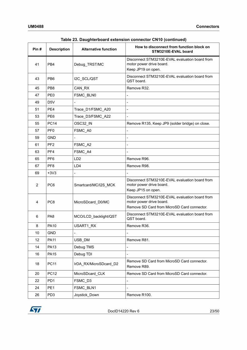
3.11 USB type B connector CN14
Figure 13. USB type B connector CN14 (top view)
3.12 Audio jack CN15A 3.5 mm stereo audio jack CN15 connected to the audio DAC is available on the STM3210E-EVAL board.
3.13 TFT LCD connector CN16One 30-pin male header is available on the board to connect the LCD module board MB895 to the FSMC interface of the STM32F103ZGT6. Refer to Section 2.17: Display and input devices on page 15 for details.
3.14 Power connector CN17Your STM3210E-EVAL board can be powered from a DC 5 V power supply via the external power supply jack (CN17) shown in Figure 14. The central pin of CN17 must be positive.
Figure 14. Power supply connector CN17 (front view)
Table 27. USB type B connector CN14Pin number Description Pin number Description
1 VBUS (power) 4 GND
2 PA11 5,6 Shield
3 PA12
MS32861V1
MS32862V1
DC +5V
GND

Connectors UM0488
30/50 DocID14220 Rev 6
3.15 Smartcard connector CN18
Figure 15. Smartcard connector CN18 (front view)
Table 28. Smartcard connector CN18Pin number Description Pin number Description
1 VCC 5 GND
2 RST 6 NC
3 CLK 7 I/O
4 NC 8 NC
17 Detection pin of card presence 18 Detection pin of card presence
5 6 7 8
1 2 3 4
17 18
MS32814V1

DocID14220 Rev 6 31/50
UM0488 Schematic diagrams
49
4 Schematic diagrams
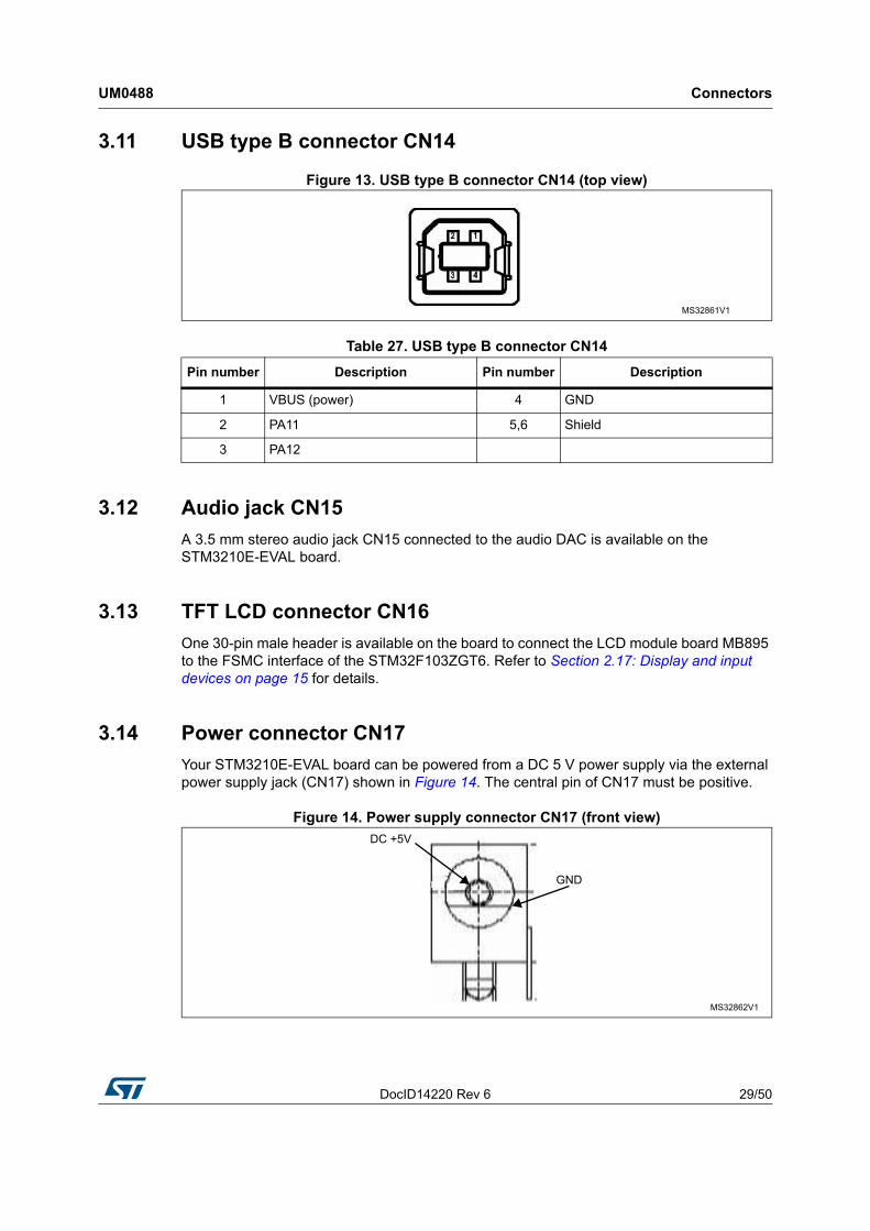
This section provides the design schematics for the STM3210E-EVAL board key features, to help you implement these features in your applications. Schematics are provided for:• Microcontroller connections, see Figure 16• MCU, see Figure 17• Peripherals, see Figure 18• RS-232 and IrDA, see Figure 19• Audio, see Figure 20• LCD and joystick, see Figure 21• SD Card and smartcard, see Figure 22• Motor control, see Figure 23• JTAG and trace, see Figure 24• Power supply, see Figure 25• SRAM and Flash, see Figure 26• Color LCD module, see Figure 27

Schematic diagrams UM0488
32/50 DocID14220 Rev 6
Figure 16. Microcontroller
11
22
33
44
55
66
77
88
DD
CC
BB
AA
STM
icro
elec
troni
csTi
tle:
Num
ber:
Rev
:S
hee
t
of
D.2
(PC
B.S
CH)
Dat
e:6/
4/20
13M
B672
111
STM
3210
E-E
VAL
I2S
_CM
DI2
S_D
INI2
S_C
KM
CO
Aud
io_S
CKA
udio
_SD
AA
udio
_LIN
Aud
io_R
IN
I2S
_MCK
Aud
io_P
DN
U_A
udio
Aud
io.S
chD
oc
A[0.
.23]
D[0
..15]
FSM
C_N
E3FS
MC
_NC
E2FS
MC
_NE2
FSM
C_N
WEFS
MC
_NOE
FSM
C_N
BL0
FSM
C_N
BL1
FSM
C_N
WA
ITFS
MC
_IN
T2
U_S
RA
M&
Flash
SR
AM
&Fla
sh.S
chD
oc US
AR
T2_R
X
US
AR
T2_T
XU
SA
RT2_
RTS
US
AR
T2_C
TS
US
AR
T1_T
XU
SA
RT1
_RX
IrDA
_RX
IrDA
_TX
U_R
S232
&IrD
AR
S23
2&Ir
DA.
Sch
Doc
Flas
h_C
SFl
ash_
SCK
Flas
h_M
ISO
Flas
h_M
OS
I
LED4
LED3
LED1
LED2
US
B_D
MU
SB
_DP
US
B_D
isco
nnec
t
Tem
pera
tureS
enso
r_IN
T
Tem
pera
tureS
enso
r_SC
LTe
mpe
ratu
reSen
sor_
SDAB
NC1
CA
N_T
XC
AN
_RX
Pote
ntio
mete
r
BN
C2B
NC3
U_P
eriph
eral
sPe
riphe
rals
.SchD
oc
MC
_Em
ergen
cyST
OP
MC
_Cur
rent
AM
C_C
urre
ntB
MC
_Cur
rent
C
MC
_PFC
sync
1M
C_P
FCsy
nc2
MC
_WL
MC
_VH
MC
_VL
MC
_UH
MC
_UL
MC
_WH
MC
_NTC
MC
_Dis
sipa
tiveB
rake
MC
_PFC
pwm
MC
_En
AM
C_E
nB
MC
_Hea
tsin
kTem
pera
ture
MC
_Bus
Volta
geM
C_E
nInd
ex
BN
C1B
NC2
BN
C3
U_M
otor
Ctrl
Mot
orC
trl.S
chD
oc
U_P
ower
Pow
er.S
chD
oc
TDI
RE
SE
T#
TRA
CE_
D3
TRA
CE_
D2
TRA
CE_
D1
TRA
CE_
D0
TRA
CE_
CK
TRST
TMS
/SWD
IOTC
K/SW
CLK
TDO
/SWO
U_J
TA
G&
SW
DJT
AG
&SW
D.S
chD
oc
TDI
TRA
CE_
CK
TMS
/SWD
IOTC
K/SW
CLK
TDO
/SWO
US
AR
T2_R
X
US
AR
T2_T
XU
SA
RT2_
RTS
US
AR
T2_C
TS
US
AR
T1_T
XU
SA
RT1
_RX
IrDA
_RX
IrDA
_TX
MC
_Em
ergen
cyST
OP
MC
_Cur
rentA
MC
_Cur
rentB
MC
_Cur
rentC
MC
_PFC
sync1
MC
_PFC
sync2
MC
_WL
MC
_VH
MC
_VL
MC
_UH
MC
_UL
MC
_WH
MC
_NTC
MC
_Dis
sipa
tiveB
rake
MC
_PFC
pw
m
MC
_EnA
MC
_EnB
MC
_Hea
tsin
kTem
pera
ture
MC
_Bus
Volta
geM
C_E
nInd
ex
JOY_
SEL
JOY_
DO
WN
JOY_
LEFT
JOY_
RIG
HTJO
Y_UP
LCD
_CS
LCD
_bac
klig
ht
Ant
i_T
ampe
rW
AKE
UPU
ser_
But
ton
SP
I1_C
SS
PI1
_SC
K
SP
I1_M
ISOS
PI1
_MO
SI
LED
4LE
D3
LED
1LE
D2
US
B_D
MU
SB
_DP
US
B_D
isco
nnec
t
Tem
pera
tureS
enso
r_IN
T
CA
N_T
XC
AN
_RX
Pote
ntio
mete
r
FSM
C_N
E3
A[0.
.23]
D[0
..15]
FSM
C_N
E4
FSM
C_N
CE2
FSM
C_N
E2FS
MC
_NWE
FSM
C_N
OEFS
MC
_NB
L0FS
MC
_NB
L1
FSM
C_N
WA
ITFS
MC
_IN
T2
Mic
roS
DCa
rd_C
LKM
icro
SD
Card
_CM
D
Sm
artC
ard_
3/5V
Sm
artC
ard_
IOS
mar
tCar
d_R
STS
mar
tCar
d_C
LKS
mar
tCar
d_O
FF
Sm
artC
ard_
CM
DV
CC
Mic
roS
DCa
rd_D
0
I2S
_CM
DI2
S_D
INI2
S_C
KM
COI2
C_S
CK
I2C
_SD
A
Mic
roS
DCa
rd_D
1M
icro
SD
Card
_D2
Mic
roS
DCa
rd_D
3
RE
SE
T#
TRA
CE_
D3
TRA
CE_
D2
TRA
CE_
D1
TRA
CE_
D0
TRST
Aud
io_L
INA
udio
_RIN
Mic
roS
DCa
rd_D
etec
t
I2S
_MCK
Aud
io_P
DN
U_M
CUM
CU
.Sch
Doc
Mic
roS
DCa
rd_C
LKM
icro
SD
Card
_CM
D
Sm
artC
ard
_3/5
VS
mar
tCa
rd_I
OS
mar
tCa
rd_R
STS
mar
tCa
rd_C
LKS
mar
tCa
rd_O
FF
Sm
artC
ard
_CM
DV
CC
Mic
roS
DC
ard_
D0M
icro
SD
Card
_D1
Mic
roS
DCa
rd_D
2M
icro
SD
Card
_D3
Mic
roS
DCa
rd_D
etec
t
U_S
D&
Sm
art C
ard
SD&
Sm
art C
ard.
Sch
Doc
JOY_
SEL
JOY_
DO
WN
JOY_
LEFT
JOY_
RIG
HTJO
Y_UP
LCD
_CS
LCD
_CLK
LCD
_DI
RE
SE
T#
LCD
_bac
klig
ht
Ant
i_T
ampe
rW
AKE
UPU
ser_
But
ton
FSM
C_N
E4
D[0
..15]
A[0.
.23]
FSM
C_N
WE
FSM
C_N
OE
LCD
_DO
U_L
CD
&Jo
ystic
kLC
D&
Joys
tick.S
chD
oc

DocID14220 Rev 6 33/50
UM0488 Schematic diagrams
49
Figure 17. MCU
11
22
33
44
55
66
77
88
DD
CC
BB
AA
STM
icro
elec
troni
csTi
tle:
Num
ber:
Rev
:S
hee
t
of
D.2
(PC
B.S
CH)
Dat
e:6/
4/20
13M
B672
211
STM
3210
E-E
VA
L M
CU
MCU
D5V
D5V
PA
0
PA
1P
A2
PA
3P
A4
PA
5P
A6
PA
7
PA
8P
A9
PA
10
PA
11P
A12
PA
13P
A14
PA
15
PB
0
PB
1P
B2
PB
3P
B4
PB
5P
B6
PB
7P
B8
PB
9
PB
10P
B11
PB
12P
B13
PB
14P
B15
PC
0P
C1
PC
2P
C3
PC
4P
C5
PC
6P
C7
PC
8P
C9
PC
10P
C11
PC
12
PC
13P
C14
PC
15
PD
0P
D1
PD
2P
D3
PD
4P
D5
PD
6P
D7
PD
8P
D9
PD
10P
D11
PD
12P
D13
PD
14P
D15
PF0
PF1
PF2
PF3
PF4
PF5
PF6
PF7
PF8
PF9
PF1
0
PF1
1P
F12
PF1
3P
F14
PF1
5
PE3
PE4
PE5
PE6
PE7
PE8
PE9
PE
10
PE
11P
E12
PE
13P
E14
PE
15
PE0
PE1
PE2
PG
0P
G1
PG
2P
G3
PG
4P
G5
PG
6P
G7
PG
8
PG
9P
G10
PG
11P
G12
PG
13P
G14
PG
15
RE
SE
T#R
1482
0R
1182
0P
C13
12
34
56
78
910
1112
1314
1516
1718
1920
2122
2324
2526
2728
2930
3132
3334
3536
3738
3940
4142
4344
4546
4748
4950
5152
5354
5556
5758
5960
6162
6364
6566
6768
6970
CN
11
Head
er 35
X2
12
34
56
78
910
1112
1314
1516
1718
1920
2122
2324
2526
2728
2930
3132
3334
3536
3738
3940
4142
4344
4546
4748
4950
5152
5354
5556
5758
5960
6162
6364
6566
6768
6970
CN
10
Head
er 35
X2
+3V3+3
V3
Ext
ensi
on c
onne
ctor
TDI
TMS
/SWD
IOTC
K/SW
CLK
US
AR
T2_R
X
US
AR
T2_T
X
US
AR
T2_R
TS
US
AR
T2_C
TS
US
AR
T1_T
XU
SA
RT1
_RX
MC
_Em
ergen
cyST
OP
MC
_UL
MC
_Dis
sipa
tiveB
rake
MC
_EnA
MC
_EnB
MC
_EnI
ndex
LCD
_bac
klig
ht
WA
KEUP
SP
I1_S
CK
SP
I1_M
ISO
SP
I1_M
OS
IU
SB
_DM
US
B_D
P
I2S
_CMD
I2S
_DIN
I2S
_CK
MCO
PA
0P
A1
PA
2P
A3
PA
4P
A5
PA
6P
A7
PA
8P
A9
PA
10P
A11
PA
12P
A13
PA
14P
A15
32
1 JP4
Aud
io_R
IN
Aud
io_L
INJP
3
TRST
TDO
/SWO
MC
_PFC
sync1
MC
_WL
MC
_VL
MC
_NTCMC
_PFC
pw
m
SP
I1_C
S
Tem
pera
tureS
enso
r_IN
TC
AN
_TX
CA
N_R
X
Sm
artC
ard_3
/5V
Sm
artC
ard_I
OS
mar
tCard
_RST
Sm
artC
ard_C
LK
I2C
_SCK
I2C
_SDA
PB
0P
B1
PB
2P
B3
PB
4P
B5
PB
6P
B7
PB
8P
B9
PB
10P
B11
PB
12P
B13
PB
14P
B15
R43
10K
+3V3
231
BO
OT1
IrDA
_RX
IrDA
_TX
MC
_Cur
rentA
MC
_Cur
rent
BM
C_C
urre
ntC
MC
_VH
MC
_UH
MC
_WH
Mic
roS
DCa
rd_C
LK
Sm
artC
ard_O
FF
Sm
artC
ard_C
MD
VCC
Mic
roS
DCa
rd_D
0M
icro
SD
Card
_D1
Mic
roS
DCa
rd_D
2
Mic
roS
DCa
rd_D
3
JP16
JP22
MC
_Bus
Volta
ge
MC
_Hea
tsin
kTem
pera
ture
Pote
ntio
mete
r
Ant
i_T
ampe
r
41
32
X2
MC
306-
G-0
6Q-3
2.76
8 (m
anuf
actu
rer
JFV
NY
)
C44
10pF
C43
10pF
R39
0
1
43
2
B1
RE
SET
R11
910
K
+3V3
C94
100n
F
C48
20pF
C47
20pF
X1
8MHz
(w
ith s
ocket
)
R40
390
R45
10K
+3V3
231
BO
OT0
RE
SE
T#
RE
SE
T#
MC
_PFC
sync2
FSM
C_N
CE2
FSM
C_N
WE
FSM
C_N
OE
FSM
C_N
WA
IT
Mic
roS
DCa
rd_C
MD
FSM
C_N
BL0
TRA
CE_
CK
TRA
CE_
D3
TRA
CE_
D2
TRA
CE_
D1
TRA
CE_
D0
Use
r_B
utto
n
LED3
LED1
LED2
US
B_D
isco
nnec
t
JOY_
SEL
JOY_
DO
WN
JOY_
LEFT
JOY_
RIG
HT
JOY_
UP
FSM
C_N
E2
FSM
C_I
NT2
JP11
PC
0P
C1
PC
2P
C3
PC
4P
C5
PC
6P
C7
PC
8P
C9
PC
10P
C11
PC
12P
C13
PC
14P
C15
PD
0P
D1
PD
2P
D3
PD
4P
D5
PD
6P
D7
PD
8P
D9
PD
10P
D11
PD
12P
D13
PD
14P
D15
D2
D3
A16
D13
D14
D15
A17
A18
D0
D1
A19
A20
A21
A22
A23
D4
D5
D6
D7
D8
D9
D10
D11
D12
A0A1A2A3A4A5
LED4
LCD
_CS
A6A7A8A9A10
A11
A12
A13
A14
A15
D[0
..15]
A[0.
.23]
A[0.
.23]
D[0
..15]
PF0
PF1
PF2
PF3
PF4
PF5
PF6
PF7
PF8
PF9
PF1
0P
F11
PF1
2P
F13
PF1
4P
F15
PE2
PE3
PE4
PE5
PE6
PE7
PE8
PE9
PE
10P
E11
PE
12P
E13
PE
14P
E15
PE0
PE1
PG
0P
G1
PG
2P
G3
PG
4P
G5
PG
6P
G7
PG
8P
G9
PG
10P
G11
PG
12P
G13
PG
14P
G15
QST
con
nect
or
PA
5
+5V
PA
6P
A7
PB
1P
F11
PB
5
PB
6P
B7
IC14
9-14
4-04
5-B
5
R31
0
R2
do n
ot fit
PE2
1
PF2
12
OS
C_I
N23
PA
0-W
KUP
34
PC
545
PG
056
PE
1063
PE
1164
PE3
2P
E43
PE5
4P
E65
PC
13-A
NTI_
TA
MP
7
PC
14-O
SC3
2_IN
8
PC
15-O
SC3
2_O
UT9
PF0
10P
F111
PF3
13P
F414
PF5
15P
F618
PF7
19P
F820
PF9
21P
F10
22
OS
C_O
UT
24
NR
ST25
PC
026
PC
127
PC
228
PC
329
PA
135
PA
236
PA
337
PA
440
PA
541
PA
642
PA
743
PC
444
PB
046
PB
147
PB
248
PF1
149
PF1
250
PF1
353
PF1
454
PF1
555
PG
157
PE7
58P
E859
PE9
60
PE
1265
PB
1576
PG
287
PC
898
PA
1410
9
PG
1112
6P
G12
127
PG
1312
8
PE
1366
PE
1467
PE
1568
PB
1069
PB
1170
PB
1273
PB
1374
PB
1475
PD
877
PD
978
PD
1079
PD
1180
PD
1281
PD
1382
PD
1485
PD
1586
PG
388
PG
489
PG
590
PG
691
PG
792
PG
893
PC
696
PC
797
PC
999
PA
810
0
PA
910
1
PA
1010
2
PA
1110
3
PA
1210
4
PA
1310
5
NC10
6
PA
1511
0
PC
1011
1
PC
1111
2
PC
1211
3
PD
011
4P
D1
115
PD
211
6P
D3
117
PD
411
8P
D5
119
PD
612
2P
D7
123
PG
912
4P
G10
125
PG
1412
9
PB
713
7
BO
OT
013
8
PB
813
9
PB
914
0
PE0
141
PE1
142
PG
1513
2
PB
313
3
PB
413
4
PB
513
5
PB
613
6
U8A
STM
32F1
03ZE
T6
PA
8
12
34
56
78
910
1112
1314
CN6
Head
er 7X
2
+5V
Mic
roS
DCa
rd_D
etec
t
TP11
MCO
I2S
_MCKJP
15
Defa
ult
settin
g:2<
->3
Defa
ult
settin
g:O
pen
Defa
ult
settin
g:cl
ose
Defa
ult
settin
g:cl
ose
Defa
ult
settin
g:cl
ose
Defa
ult
settin
g:O
pen
TP1
Gro
und
TP2
Gro
und
JP9
JP10
FSM
C_N
E3
FSM
C_N
E4
FSM
C_N
BL1
Aud
io_P
DN
(Rig
ht)
(Lef
t)
+3V3
JP17
Defa
ult
settin
g:cl
ose
R13
50

Schematic diagrams UM0488
34/50 DocID14220 Rev 6
Figure 18. Peripherals
11
22
33
44
DD
CC
BB
AA
STM
icro
elec
troni
csTi
tle:
Num
ber:
Rev:
Shee
t
ofD
.2(P
CB
.SC
H)D
ate:
6/4/
2013
+3V3
+3V3
C14
100n
F
HO
LD7
VCC
8
S1
Q2
W3
VSS
4D
5C
6U6 M
25P6
4-V
ME
6G
SDA
1
SCL
2
OS
/INT
3
GND
4A2
5A1
6A0
7V
DD8
U9 STL
M75
M2E
+3V3
+3V3
C49
100n
F
U5V
C74
100n
FV
CC1
D-
2
D+
3
GND
4
SH
ELL
0
SH
ELL
0
CN
14U
SB
-type
B co
nnec
tor
R69
1.5K
R70
10K
U5V
R65
36K
2
31
T2 9013
+3V3
I/O1
1
GND
2
I/O2
3I/O
24
Vbus
5I/O
16
U11
US
BLC
6-2P
6
U5V
R95
1MC
784.
7nF
2
31
T1 9013
R66
47K
+3V3
32
1
JP14
D1
GND
2
VCC
3
R4
Vre
f5
CA
NL
6C
ANH
7RS
8U4 SN
65H
VD2
30
1 6 2 7 3 8 4 9 5
CN
4D
B9
-male
CA
N co
nnec
tor
+3V3
+3V3
R28
120
JP6
32
1
JP8
R26
10K
+3V3
C27
100n
F
12
LD3
Red
12
LD2
Ora
nge 1
2
LD4
Blu
e12
LD1
Gre
en
12345
CN3
VB
334
MB
672
311
STM
3210
E-E
VA
L P
erip
hera
ls
R27
0
R35
0R
370
13
2R
V110
KR
126
0
+3V3
R46
0R
440
R38
0
R96
600
R97
600
R98
600
R99
600
R32
0
Flas
h_CS
Flas
h_SC
K
Flas
h_M
ISO
Flas
h_M
OS
I
LED4
LED3
LED1
LED2
US
B_D
M
US
B_D
P US
B_D
isco
nnec
t
Tem
pera
tureS
enso
r_IN
TTe
mpe
ratur
eSen
sor_
SCL
Tem
pera
tureS
enso
r_S
DA
BN
C1
CA
N_TX
CA
N_RX
Pote
ntio
met
er SP
I Fla
sh
BN
C c
onne
ctor
Pot
entio
met
er
Tem
pera
ture
sens
or
CAN
USB
12345
CN5
VB
334
BN
C2
12345
CN
2V
B33
4
BN
C3
R9 0R
10do
not
fit
LED
R82
0
R81
0
Def
ault
setti
ng: 1
<->2
Def
ault
setti
ng: O
pen
R51
4K7
PA
12
PA
11
PB14
PB8
PB9
PB6
PB7
PB5
PF7
PF6
PF9
PF8
PC2
PC1
PC3
PC4
PB2
PA6
PA5
PA7
JP25
R13
650
R13
750
R13
850
JP24
JP23
JP23
-25
Def
ault
setti
ng:op
en
C10
010
nF
DocID14220 Rev 6 35/50
UM0488 Schematic diagrams
49
Figure 19. RS-232 and IrDA
11
22
33
44
DD
CC
BB
AA
STM
icro
elec
troni
csTi
tle:
Num
ber:
Rev:
Shee
t
ofD
.2(P
CB
.SC
H)D
ate:
6/4/
2013
SD
5
TxD
3
GN
D8
Anod
e (V
CC2)
1
Cath
ode
2
RxD
4
VC
C16
Vlo
gic
7
U13
TFD
U430
0
R92
5R
85
47
C68
0.1u
FC
720.
1uF
+3V3
C77
4.7u
FC
714.
7uF
R88
10K
+3V3
JP21
R2o
ut9
R2in
8
T1in
11
R1o
ut12
T1ou
t14
R1in
13
T2in
10T2
out
7
C1+
1
C1-
3C
2+4
C2-
5
V+2
V-
6
VCC
16
GND
15
U5 ST3
232E
CTR
C37
100n
F
C29
100n
F
C30
100n
F
C28
100n
F
C31
100n
F
+3V3
1 6 2 7 3 8 4 9 5
CN
8D
B9-m
ale
US
ART2
R33
do n
ot fit
R2o
ut9
R2in
8
T1in
11
R1o
ut12
T1ou
t14
R1in
13
T2in
10T2
out
7
C1+
1
C1-
3C
2+4
C2-
5
V+2
V-
6
VCC
16
GND
15
U7 ST3
232E
CTR
C52
100n
F
C41
100n
F
C40
100n
F
C39
100n
F
C42
100n
F
+3V3
1 6 2 7 3 8 4 9 5
CN
12D
B9-m
ale
US
ART1
R62
do n
ot fit
RS23
2_TX
2
RS23
2_R
X2
RS23
2_C
TS2
RS23
2_R
TS2
RS23
2_R
X1
RS23
2_TX
1
MB
672
411
STM
3210
E-E
VA
L R
S-2
32 &
IrD
A
R36
0
R89
0
R2
90
R30
0
US
AR
T2_R
X
US
AR
T2_T
X
US
AR
T2_R
TS
US
AR
T2_C
TS
US
AR
T1_T
X
US
AR
T1_R
X
IrDA_
RXIrD
A_TX
conn
ecto
r fo
r U
SA
RT2
conn
ecto
r fo
r U
SA
RT1
IrDA
R34
10K
Def
ault
setti
ng: c
lose
PA0
PA1
PA2
PA3
PA9
PA
10
PC10
PC11

Schematic diagrams UM0488
36/50 DocID14220 Rev 6
Figure 20. Audio
11
22
33
44
DD
CC
BB
AA
STM
icro
elec
troni
csTi
tle:
Num
ber:
Rev:
Shee
t
ofD
.2(P
CB
.SC
H)D
ate:
6/4/
2013
MB
672
511
STM
3210
E-E
VA
L A
udio
I2S_
CM
DI2
S_D
IN
I2S_
CK
32
1 JP18
MCO
Jum
per
to se
lect
PLL
slav
e cl
ock
mod
e:1.
1<-
>2 re
fere
nce
cloc
k M
CKI
2. 2
<->3
refe
renc
e cl
ock
BIC
K or
LRC
K
TP7
MC
KO
+3V3
R72
10K
C59
1uF
Audi
o_SC
KAu
dio_
SDA
I2C
contr
ol i
nterfa
ce s
elect
ed (
share
with
te
mpe
ratu
re s
ensor
) by
con
necti
ng p
in "
I2C
" to
high
, th
e sl
ave a
ddres
s is
set to
"00
1001
1"
by p
ull u
p pi
n "C
AD
0".
C65
10uF
C54
100n
FC
532.
2uF
C34
100n
F
+3V3
C73
10uF
C66
100n
F
C79
10uF
C16
100n
F
+3V3
+3V3
R83
10
C67
0.22
uF
R73
10
C76
0.22
uF
R86
10
R87
6.8
R84
6.8
C80
47uF
C70
47uF
12 3
CN
15
ST-
225-
02
1 2U
14K
SS
-1508
CCL
K/S
CL9
CD
TI/S
DA10
SD
TI11
TES
T212
LRCK
13
BIC
K14
DV
DD15
DV
SS16
MUT
ET25
RO
UT/
RCN
26LO
UT/
RC
P27
MIN
/LIN
328
RIN
2/IN
2-29
LIN
2/IN
2+30
LIN
1/IN
1-31
RIN
1/IN
1+32
TES
T11
VC
OM2
AV
SS3
AV
DD4
VC
OC
/RIN
35
I2C
6
PDN
7
CSN
/CA
D08
MC
KI
17M
CK
O18
SPN
19S
PP20
HV
DD21
HV
SS22
HPR
23H
PL24
U10
AK
4343
Audi
o_RI
NAu
dio_
LIN
C56
1uF
C57
1uF
C58
do n
ot fit
C55
do n
ot fitR
670
R68
0
TP9
RIN
TP6
LIN
TP10
HPL
TP8
HPR
TP12
SPP
TP13
SPN
I2S
_MCK
R56
0
R57 do
not
fit
Def
ault
setti
ng: 1
<->2
PC6
PA8
PB12
PB13
PB15
PB7
PB6
PA5
PA4
R12
80
Audi
o_PD
NP
G11

DocID14220 Rev 6 37/50
UM0488 Schematic diagrams
49
Figure 21. LCD and joystick
11
22
33
44
DD
CC
BB
AA
STM
icro
elec
troni
csTi
tle:
Num
ber:
Rev:
Shee
t
ofD
.2(P
CB
.SC
H)D
ate:
6/4/
2013
R11210KR11410KR11510KR11610K
R11310K
+3V3
C99100nF
C98100nF
C97100nF
C95100nF
C96100nF
R12
510
0C
OM
MON
5
Sel
ectio
n2
DWO
N3
LEFT
1
RIG
HT
4
UP6
U19
MT0
08-
A
R12
322
0K
1
4 3
2
B2 WK
UP
C91
do n
ot fit
+3V3
R12
010
0R
122
4K7
1
43
2
B4 US
ERC
9310
0nF
+3V3
R11
710
0
R12
14K
7
1
43
2
B3 Tamp
erC
9210
0nF
+3V3
R12
410
0
MB
672
611
STM
3210
E-E
VA
L LC
D&J
oyst
ick
Vss
1
Vcc
2
VO3
CLK
4
SID
5
CS6
A7
K8
U18
HX
M12
2032
-GB
1 (d
o no
t fit
)
+3V3
R79
0
R76
do n
ot f
itR
74do
not
fit
+5V
+3V3
C64
100n
F
R10
40
R10
30
R10
20
R10
00
R10
10
R11
033
0
R10
60
R11
10
+3V3
+3V3
JOY_
SEL
JOY_
DO
WN
JOY
_LE
FTJO
Y_R
IGH
TJO
Y_UP
LCD_
CS
LCD_
CLK
LCD_
DI
RE
SE
T#
LCD
_bac
kligh
t
Anti_
Tam
per
WA
KE
UP
Use
r_But
ton
R10
5do
not
fit
R10
70
+3V3
Joys
tick
TFT
LCD G
ray
LCD
Tam
per
But
ton
Wak
eup
But
ton
Use
r But
ton
D[0
..15]
A[0
..23]
A[0
..23]
D[0
..15]
D0
D1
D2
D3
D4
D5
D6
D7
D8
D9
D10
D11
D12
D13
D14
D15
FSM
C_N
WE
FSM
C_N
OE
A0CS
1
RS2
WR
/SCL
3
RD4
RE
SET
5
VDD
24
VCI
25
GND
26
GND
27
BL_
VDD
28
BL_
Con
trol
23B
L_G
ND22
PD1
6
PD2
7
PD3
8
PD4
9
PD5
10
PD6
11
PD7
12
PD8
13
PD
1014
PD
1115
PD
1216
PD
1317
PD
1418
PD
1519
PD
1620
PD
1721
SDO
29
SDI
30
CN
16
Con
nect
or t
o M
othe
r bo
ard
R78
do n
ot f
it
R75
do n
ot f
it
R77
0
R80
0
LCD_
DO
PG7
PD3
PG
14P
G13
PG
15
PG8
PC13
PA0
PG
12P
D5 PD4
PA8
PA6 P
A5P
A7PF
10
FSM
C_N
E4
JP26
JP27

Schematic diagrams UM0488
38/50 DocID14220 Rev 6
Figure 22. SD Card and smartcard
11
22
33
44
DCBA
STM
icro
elec
troni
csTi
tle:
Num
ber:
Rev:
Shee
t
ofD
.2(P
CB
.SC
H)D
ate:
6/4/
2013
MB
672
711
STM
3210
E-E
VA
L S
D &
sm
artc
ard
+3V3
Mic
roS
DCar
d_CL
KM
icro
SDC
ard_
CM
D
Mic
roS
D c
ard
VCC
1
RST
2
CLK
3
NC4
GND
5
NC6
I/O
7
NC8
1817C
N18
C81
6
CLK
DIV1
1
CLK
DIV2
2
5V/3
V3
PG
ND4
C1+
5
Vddp
6
C1-
7
Vup
8
PRE
S9
PRE
S10
I/O
11
AU
X212
AU
X113
CG
ND14
CLK
15R
ST16
Vcc
17P
OR
ADJ
18C
MD
VC
C19
RSTI
N20
Vdd
21G
ND
22O
FF23
XTA
L124
XTA
L225
I/OUC
26A
UX
1UC
27A
UX
2UC
28U
17
ST8
024C
DR
C87
100n
F
C83
100n
FC
8633
0nF
C82
47uF
+5V
C89
100n
F
C90
100n
F
R11
810
0K+3
V3
R90
4K7
+3V3
R10
810
K
R10
910
K
+3V3
C12
100n
FC
8447
uF
+3V3
R91
10K
+3V3
R94
0
R71
0
R93
10K
TP14
AU
X2TP
15A
UX1
Smar
tCar
d_3/
5V
Smar
tCar
d_IO
Smar
tCar
d_R
ST
Smar
tCar
d_C
LKSm
artC
ard_
OFF
Smar
tCar
d_C
MD
VC
C
Sm
artc
ard
SM
S06
4FF
or S
MS
128F
F
12345678
SW2 9
SW1 10
CN
13P
JS00
8-20
00
Mic
roS
DCar
d_D0
Mic
roS
DCar
d_D1
Mic
roS
DCar
d_D2
Mic
roS
DCar
d_D3
Mic
roS
DCar
d_D
etec
t
PB12
PB0 P
C6
PC
7 PB11
PB10
PC8
PC9
PC10
PC11
PD2
PC12
R13
047
KR
131
47K
+3V3
R12
90
R13
347
KR
134
47K
R13
247
K
PF11

DocID14220 Rev 6 39/50
UM0488 Schematic diagrams
49
Figure 23. Motor control
11
22
33
44
DD
CC
BB
AA
STM
icro
elec
troni
csTi
tle:
Num
ber:
Rev:
Shee
t
ofD
.2(P
CB
.SC
H)D
ate:
6/4/
2013
R7 3.3K C8 1n
F
+3V3
+3V3
+5V
R8 0
C7 100n
F
C6 100n
F
R50
C22
do n
ot fit
C13
do n
ot fit
C9 do n
ot fit
MB
672
811
STM
3210
E-E
VA
L M
otor
Con
trol
C60
do n
ot fit
C5 do n
ot fit
C2 10nF
C4 do n
ot fit
C3 do n
ot fit
R40
R30
R6 0 R1 0
JP20
C51
do n
ot fit
EM
ER
GE
NC
Y STO
P1
MC
-UH
3
MC
_UL
5
MC
_VH
7
MC
_VL
9
MC
_WH
11
MC
_WL
13
CU
RRE
NT
A15
CU
RRE
NT
C19
CU
RRE
NT
B17
NTC
BY
PA
SS R
ELA
Y21
DIS
SIP
ATI
VE B
RA
KE23
+5V
POW
ER25
PFC
SY
NC27
PFC
PW
M29
Enco
der
A31
Enco
der
B33
GND
2
GND
4
GND
6
GND
8
GND
10
GND
12
BU
S V
OLT
AG
E14
GND
16
GND
18
GND
20
GND
22
GND
24
Hea
tsink
Tem
pera
ture
26
3.3V
Pow
er28
GND
30
GND
32
Enco
der I
ndex
34
CN1
MC
_con
nect
or
MC
_Em
erge
ncyS
TOP
MC
_Cur
rent
A
MC
_Cur
rent
B
MC
_Cur
rent
C
MC
_PF
Csy
nc1
MC
_PF
Csy
nc2
MC
_WL
MC
_VH
MC
_VL
MC
_UH
MC
_UL
MC
_WH
MC
_NTC
MC
_Dis
sipat
iveB
rake
MC
_PF
Cpw
mM
C_E
nAM
C_E
nB
MC
_Hea
tsin
kTem
pera
ture
MC
_Bus
Volta
ge
MC
_EnIn
dex
R63
100K
JP2
C1 do n
ot fit
Mot
or c
ontro
l co
nnec
tor
Def
ault
setti
ng: O
pen
Def
ault
setti
ng: O
pen
PA6
PC6
PA7
PC7
PB0
PC8
PB1
PA3
PA0
PA1
PA2
PC0
PC3
PB4
PB5
PB12
PD2
PC1
PC2
PC5
BN
C1B
NC2
BN
C3

Schematic diagrams UM0488
40/50 DocID14220 Rev 6
Figure 24. JTAG and trace connectors
11
22
33
44
DD
CC
BB
AA
STM
icro
elec
troni
csTi
tle:
Num
ber:
Rev:
Shee
t
ofD
.2(P
CB
.SC
H)D
ate:
6/4/
2013
1 2 3 4 5 6 7 8 9 10 11 12 13 14 15 16 17 18 19 20
CN7
FTS
H-1
10-0
1-L-
DV
MB
672
911
STM
3210
E-E
VA
L JT
AG
& T
race
+3V3
R58
10K
R54
10K
R53
10K
R59
10K
R55
do n
ot fit
+3V3
1 2 3 4 5 6 7 8 9 10 11 12 13 14 15 16 17 18 19 20
CN9
JTAG
+3V3
+3V3
R48
10K
R47
10K
R52
10K
JP19
R64
10K
R49
0R
50do
not
fitR
600
R61
do n
ot fit
TDI
RE
SE
T#
TRA
CE_
D3
TRA
CE_
D2
TRA
CE_
D1
TRA
CE_
D0
TRA
CE_
CK
TRST
TMS
/SW
DIO
TCK
/SWC
LKTD
O/S
WO
Trac
e c
onne
ctor
JTA
G c
onne
ctor
Def
ault
setti
ng: O
pen
PB4
PB3
PA
15
PA
14P
A13
PE2
PE3
PE4
PE5
PE6
KEY

DocID14220 Rev 6 41/50
UM0488 Schematic diagrams
49
Figure 25. Power supply
11
22
33
44
DD
CC
BB
AA
STM
icro
elec
troni
csTi
tle:
Num
ber:
Rev:
Shee
t
ofD
.2(P
CB
.SC
H)D
ate:
6/4/
2013
Vin
3
GND 1
Vout
2
U12
LD1
086D
2M33
C61
220u
FC
6947
uFC
1110
0nF
+5V
TP5
3V3
SV1
SG2
CV3
CG1
4
CG2
5
CG3
6
U16
BN
X002
-01
C81
10uF
E5V
TP4
5V+5
VR
127
300
12
LD5
red
Jum
per f
or c
hoic
e be
twee
n po
wer
con
nect
or, U
SB
conn
ecto
r or
dau
ghte
r bo
ard
TP16
Gro
und
1 32
CN
17
DC
-10B
Z1 SM
AJ5
.0A
-TRC
8510
0nF
1
2
3
U15
ZEN
056V
130A
24LS
+3V3
12
34
56
JP13
MB
672
1011
STM
3210
E-E
VA
L P
ower
D5V
U5V
E5V
Pow
er r
egul
ator
R42
47
R41
0
VR
EF-
L1 BE
AD
C50
10uF
C46
10nF
JP12
+3V3
VD
DA
VDD
BT1
CR12
20 h
olde
rVb
at3
21
JP1
+3V3
VD
DA
VR
EF+
C45
10nF
TP3
VR
EF
VD
D_7
62
VB
AT6
VS
S_5
16
VD
D_5
17
VS
SA30
VR
EF-
31V
RE
F+32
VD
DA
33
VS
S_4
38
VD
D_4
39
VS
S_6
51V
DD
_652
VS
S_7
61
VS
S_10
120
VS
S_1
71
VD
D_1
72
VS
S_8
83
VD
D_8
84
VS
S_9
94
VD
D_9
95V
SS
_210
7
VD
D_2
108
VD
D_1
012
1
VS
S_3
143
VD
D_3
144
VS
S_11
130
VD
D_1
113
1U
8B
STM
32F1
03Z
ET6
MC
U po
wer
C23
100n
FC
3210
0nF
C38
100n
FC
2610
0nF
C19
100n
F
C17
100n
FC
3610
0nF
C35
100n
FC
3310
0nF
C25
100n
F
C18
100n
F
VDD
VDD
Def
ault
setti
ng: 5
<->6
Def
ault
setti
ng: 2
<->3

Schematic diagrams UM0488
42/50 DocID14220 Rev 6
Figure 26. SRAM and Flash
11
22
33
44
DD
CC
BB
AA
STM
icro
elec
troni
csTi
tle:
Num
ber:
Rev:
Shee
t
ofD
.2(P
CB
.SC
H)D
ate:
6/4/
2013
+3V3
A1A2A3A4A5A6A7A8A9A10
A11
A12
A13
A14
A15
A16
A1A2A3A4A5A6A7A8A9A10
A11
A12
A13
A14
A15
A16
A17
A18
A19
A20
A21
A22
+3V3
A[0
..23]
D[0
..15]
RB7
R8
E9
VDD
12
VSS
13
CL16
AL17
W18
WP
19
I/O0
29
I/O1
30
I/O2
31
I/O3
32
VSS
36
VDD
37
I/O4
41
I/O5
42
I/O6
43
I/O7
44
U3 NA
ND
512W
3A2C
N6E+3
V3
A16
A17
+3V3
FSM
C_N
E3
FSM
C_N
E2
FSM
C_N
CE2
FSM
C_N
WE
FSM
C_N
OEFS
MC_
NWA
IT
R19
10K
D[0
..15]
A[0
..23]
MB
672
1111
STM
3210
E-E
VA
L S
RA
M &
Fla
sh
12
3 JP7
C21
100n
FC
20
100n
F
C88
100n
F
C62
100n
FR
1710
K
+3V3
R20
10K
+3V3
C75
100n
F
C63
100n
F
C24
100n
F
R13
10K
C10
100n
F
R23
10K
+3V3
R24
10K
R12
10K
+3V3
JP5
A0
A0
A17
A18
+3V3
+3V3
D0
D1
D2
D3
D4
D5
D6
D7
D8
D9
D10
D11
D12
D13
D14
D15
D0
D1
D2
D3
D4
D5
D6
D7
D8
D9
D10
D11
D12
D13
D14
D15
D0
D1
D2
D3
D4
D5
D6
D7
R22
0
R16
10K
R15
0
+3V3
R21
0
R18
10K
R25
do n
ot fit
Def
ault
setti
ng: O
pen
Def
ault
setti
ng: 2
<->3
A4B4
A3B3
A2A5
A1A4
A0A3
CEB5
I/O0
B6I/O
1C5
I/O2
C6I/O
3D
5
VCC
D6
VSS
D1
I/O4
E5I/O
5F5
I/O6
F6I/O
7G6
WE
G5
A16
E4
A15
F4
A14
F3
A13
G4
A12
G3
A11
H5
A10
H4
A9H3
A8H2
I/O8
B1I/O
9C1
I/O10
C2I/O
11D
2
VCC
E1
I/O12
E2I/O
13F2
I/O14
F1I/O
15G1
BLE
A1
BHE
B2
OE
A2
A7D
4
A6C4
A5C3
A17
D3
A18
H1
VSS
E6
U1
IS61
WV5
1216
BLL
-10M
LI
A22
B8
A15
D7
A14
C7
A13
A7
A12
B7
A11
D6
A10
C6
A9A6
A8B6
A19
D5
A20
D4
WA5
RPB5
A21
C5
Vpp/
WP
B4
RBA4
A18
C4
A17
B3
A7A3
A6C3
A5D
3
A4B2
A3A2
A2C2
A1D
2
VCC
D8
A0E2
EF2
VSS
E8
GG2
DQ0
E3
DQ8
F3
DQ1
H3
DQ9
G3
DQ2
E4
DQ
10F4
DQ3
H4
DQ
11G4
VCC
F1
DQ4
H5
DQ
12F5
DQ5
E5
DQ
13G6
DQ6
H6
DQ
14F6
DQ7
E6
DQ
15A
-1G7
VSS
H7B
YTE
F7
A16
E7
VCC
G5
VSS
H2
U2
M29
W1
28G
L70Z
A6E
C15
100n
F
M29
W1
28G
H70
ZA6E
NA
ND
512W
3A2B
N6E
PE1
PE0
PD5
PG9
PD6
PD4
PG
10P
D7
PG6
FSM
C_N
BL0
FSM
C_N
BL1
FSM
C_I
NT2
S29
GL1
28P9
0FFI
R20
Rev D
.2 m
odifi
catio
n : re
fere
nces
ofN
OR
Flas
h us
ed f
or U2
upd
ated

DocID14220 Rev 6 43/50
UM0488 Schematic diagrams
49
Figure 27. Color LCD module
11
22
33
44
DD
CC
BB
AA
STM
icro
elec
troni
csTi
tle:
Num
ber:
Rev
:S
heet
of
C.1
(PC
B.S
CH
)D
ate:
1/21
/201
1
Ena
ble
1
Dot
Clk
2
HS
YNC
3
VS
YNC
4
CS5
WR
/SCL
6
SDI
7
RS8
NC9
RD10
RE
SET
11
PD0
12PD
113
PD2
14PD
315
PD4
16PD
517
PD6
18PD
719
PD8
20PD
921
PD10
22PD
1123
PD12
24PD
1325
PD14
26PD
1527
PD16
28PD
1729
VDD
30
VCI
31
VCI
32
NC33
NC34
NC35
NC36
NC37
NC38
NC39
GND
40
NC41
NC42
NC43
NC44
GND
45
SDO
46
NC47
NC48
NC49
GND
50
GND
51
A52
K53
CN3
FH26
-51S
-0.3
SH
W(0
5)
Ena
ble
Dot
Clk
HS
YNC
VS
YNC
CS RSWR
_SCL
RD #RE
SET
A K
PD0
PD1
PD2
PD3
PD4
PD5
PD6
PD7
PD8
PD9
PD10
PD11
PD12
PD13
PD14
PD15
PD16
PD17
CS RS WR
_SCL
RD #RE
SET
VDD
VDD
BLG
ND
BLV
DDBL_C
ontro
l
Enable
DotClkHSYNC
VSYNC
VDD
RP1
10K
C3
4.7u
F/10
V
R8
4K7
R7
4K7
SDO
SDI
SDI
SDO
PD1
PD2
PD3
PD4
PD5
PD6
PD7
PD8
PD10
PD11
PD12
PD13
PD14
PD15
PD16
PD17
AM
-240
320L
DTN
QW
-00H
(S
PI)
CS1
RS2
WR
/SCL
3
RD4
RE
SET
5
VDD
24
VCI
25
GND
26
GND
27
BL_V
DD28
BL_C
ontro
l23
BL_G
ND22
PD1
6
PD2
7
PD3
8
PD4
9
PD5
10
PD6
11
PD7
12
PD8
13
PD10
14
PD11
15
PD12
16
PD13
17
PD14
18
PD15
19
PD16
20
PD17
21
SDO
29
SDI
30
CN2
16-b
it co
nnec
tor
RP2
10K
RP3
10K
RP4
10K
RP5
10K
PD0
PD1
PD2
PD3
PD4
PD5
PD6
PD7
PD8
PD9
PD10
PD11
PD12
PD13
PD14
PD15
PD16
PD17
R6
4K7
R5
4K7
SDO
SDI
R10
4K7
R9
4K7
RD
RS
Z1 STP
S1L
40M
C1
4.7u
F/35
V
L14.7u
H(1
A)
R3
10
BLG
ND
BLV
DD
R2
100K
C2
4.7u
F/10
V
R1
0
R4 [N
/A]
BLV
DD
BL_C
ontro
l
BLG
ND
BLG
ND
BLG
NDV
i1
Rse
t2
GND
3FB
4
NC5
Vo6
EN7
SW
8
PGND
9
U1 STL
D40
DPM
RCS
1
SCL
2
SDI
3
RS4
WR
5
RD6
RE
SET
8
VDD
9
VCI
10
SDO
7
GND
11
GND
12
BL_V
DD13
BL_C
ontro
l14
BL_G
ND15
BL_G
ND16
CN1
SPI
con
nect
or
CS WR
_SCL
SDI
SDO
#RE
SET
VDD
BLG
ND
BLV
DDBL
_Con
trol
AM
-240
320L
DTN
QW
-02H
(16
bit
para
llel)
MB
895
11
2.4
inch
LC
D bo
ard
supp
ort
eith
er S
PI o
r 16
-bit
para
llel
Bac
klig
ht dr
iver
& P
FC c
onne
ctor
for
LC
D pa
nel
Con
nect
or fo
r 16
-bit
para
llel a
pplic
atio
n
Con
nect
or fo
r S
PI s
eria
l app
licat
ion
mou
nt o
nly
for
SP
I app
licat
ion
Mou
nt o
nly
for
16-b
it ap
plic
atio
n
STL
D40
DPUR
C5
10nF
C4
100n
F
C6
100n
F
L2 BE
AD
C7
10nF
TP1
TP2
TP3
TP4
TP5
GND
BLG
ND
VDD
VH VL
VLVH
R15
[N/A
]
R14
[N/A
]
R13
[N/A
]
R12
[N/A
]
R11
[N/A
] BLG
ND
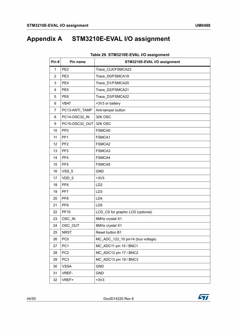
STM3210E-EVAL I/O assignment UM0488
44/50 DocID14220 Rev 6
Appendix A STM3210E-EVAL I/O assignment
Table 29. STM3210E-EVAL I/O assignmentPin # Pin name STM3210E-EVAL I/O assignment
1 PE2 Trace_CLK/FSMCA23
2 PE3 Trace_D0/FSMCA19
3 PE4 Trace_D1/FSMCA20
4 PE5 Trace_D2/FSMCA21
5 PE6 Trace_D3/FSMCA22
6 VBAT +3V3 or battery
7 PC13-ANTI_TAMP Anti-tamper button
8 PC14-OSC32_IN 32K OSC
9 PC15-OSC32_OUT 32K OSC
10 PF0 FSMCA0
11 PF1 FSMCA1
12 PF2 FSMCA2
13 PF3 FSMCA3
14 PF4 FSMCA4
15 PF5 FSMCA5
16 VSS_5 GND
17 VDD_5 +3V3
18 PF6 LD2
19 PF7 LD3
20 PF8 LD4
21 PF9 LD5
22 PF10 LCD_CS for graphic LCD (optional)
23 OSC_IN 8MHz crystal X1
24 OSC_OUT 8MHz crystal X1
25 NRST Reset button B1
26 PC0 MC_ADC_123_10 pin14 (bus voltage)
27 PC1 MC_ADC11 pin 15 / BNC1
28 PC2 MC_ADC12 pin 17 / BNC2
29 PC3 MC_ADC13 pin 19 / BNC3
30 VSSA GND
31 VREF- GND
32 VREF+ +3V3

DocID14220 Rev 6 45/50
UM0488 STM3210E-EVAL I/O assignment
49
33 VDDA +3V3
34 PA0-WKUP MC_TIM2_CH1 pin 31(Ena) / WAKEUP /USART2 CTS
35 PA1 MC_TIM2_CH2 pin 33 (EnB)/USART2 RTS
36 PA2 MC_TIM2_CH3 pin34 (EnIndex)/USART2 TX
37 PA3 MC_TIM6_CH4 pin 23 (dissipative brake)/USART2 RX
38 VSS_4 GND
39 VDD_4 +3V3
40 PA4 DAC1_Audio RIN
41 PA5 SPI_Flash_CLK / DAC2_Audio LIN / QST pin4
42 PA6 MC_STOP pin 1 (Emergency stop) / SPI_Flash_MISO / QST pin8
43 PA7 MC_TIM5_CH1N pin 5 (UL) / SPI_Flash_MOSI / QST pin6
44 PC4 Potentiometer
45 PC5 MC_ADC_12_15 pin 26 (heatsink temperature)
46 PB0 MC_TIM5_CH2N pin 9 (VL) / SmartCard_3/5
47 PB1 MC1_TIM5_CH3N pin 13 (WL) / QST pin7
48 PB2 Boot1/ NSS_SPI_Flash
49 PF11 QST pin9 / MicroSD Card detection
50 PF12 FSMCA6
51 VSS_6 GND
52 VDD_6 +3V3
53 PF13 FSMCA7
54 PF14 FSMCA8
55 PF15 FSMCA9
56 PG0 FSMCA10
57 PG1 FSMCA11
58 PE7 FSMCD4
59 PE8 FSMCD5
60 PE9 FSMCD6
61 VSS_7 GND
62 VDD_7 +3V3
63 PE10 FSMCD7
64 PE11 FSMCD8
65 PE12 FSMCD9
66 PE13 FSMCD10
67 PE14 FSMCD11
Table 29. STM3210E-EVAL I/O assignment (continued)Pin # Pin name STM3210E-EVAL I/O assignment

STM3210E-EVAL I/O assignment UM0488
46/50 DocID14220 Rev 6
68 PE15 FSMCD12
69 PB10 Smart_IO
70 PB11 Smart Reset
71 VSS_1 GND
72 VDD_1 +3V3
73 PB12 Smart_CK / MC_pin21 (NTC) / Audio I2S_CMD
74 PB13 Audio I2S_CK
75 PB14 USB Disconnect
76 PB15 Audio I2S_DIN
77 PD8 FSMCD13
78 PD9 FSMCD14
79 PD10 FSMCD15
80 PD11 FSMCA16
81 PD12 FSMCA17
82 PD13 FSMCA18
83 VSS_8 GND
84 VDD_8 +3V3
85 PD14 FSMCD0
86 PD15 FSMCD1
87 PG2 FSMCA12
88 PG3 FSMCA13
89 PG4 FSMCA14
90 PG5 FSMCA15
91 PG6 FSMC_INT2
92 PG7 JOY_Select
93 PG8 User Button B4
94 VSS_9 GND
95 VDD_9 +3V3
96 PC6 MC_TIM5_CH1 pin 3 (UH) / Smart_ CMD / VCC/I2S_MCK
97 PC7 MC_TIM5_CH2 pin 7(VH) / Smartcard_OFF
98 PC8 MC_TIM5_CH3 pin 11 (WH) / MicroSD Card D0
99 PC9 MicroSD Card D1
100 PA8 MCO / LCD backlight /QST pin11
101 PA9 USART1 TX
102 PA10 USART1 RX
Table 29. STM3210E-EVAL I/O assignment (continued)Pin # Pin name STM3210E-EVAL I/O assignment

DocID14220 Rev 6 47/50
UM0488 STM3210E-EVAL I/O assignment
49
103 PA11 USB DM
104 PA12 USB DP
105 PA13 Debug TMS
106 NC
107 VSS_2 GND
108 VDD_2 +3V3
109 PA14 Debug TCK
110 PA15 Debug TDI
111 PC10 IRDA TX / MicroSD Card D2
112 PC11 IRDA RX /MicroSD Card D3
113 PC12 MicroSD Card CLK
114 PD0 FSMCD2
115 PD1 FSMCD3
116 PD2 Sd card CMD / MC1_TIM3_ETR pin 27 (PFCsync2)
117 PD3 JOY_Down
118 PD4 FSMCNOE
119 PD5 FSMCNWE
120 VSS_10 GND
121 VDD_10 +3V3
122 PD6 FSMCNWAIT
123 PD7 FSMCNE1
124 PG9 FSMCNE2
125 PG10 FSMCNE3
126 PG11 PDN of Audio DAC
127 PG12 FSMCEBAR3
128 PG13 JOY_Right
129 PG14 JOY_Left
130 VSS_11 GND
131 VDD_11 +3V3
132 PG15 JOY_Up
133 PB3 Debug TDO
134 PB4 Debug TRST/MC_TIM3_CH1 pin 27 (PFCsync1)
135 PB5 Temperature SMBIA / MC_TIM3_CH2 pin 29 (PFC pwm)/ QST pin10
136 PB6 Audio I2C_SCL & Temperature SCL / QST pin3
137 PB7 Audio_I2C_SDA & Temperature SDA / QST pin5
Table 29. STM3210E-EVAL I/O assignment (continued)Pin # Pin name STM3210E-EVAL I/O assignment

STM3210E-EVAL I/O assignment UM0488
48/50 DocID14220 Rev 6
138 BOOT0 BOOT0
139 PB8 CAN RX
140 PB9 CAN TX
141 PE0 FSMCBLN0
142 PE1 FSMCBLN1
143 VSS_3 GND
144 VDD_3 +3V3
Table 29. STM3210E-EVAL I/O assignment (continued)Pin # Pin name STM3210E-EVAL I/O assignment

DocID14220 Rev 6 49/50
UM0488 Revision history
49
Revision history
Table 30. Document revision historyDate Revision Changes
5-May-2008 1 Initial release.
2-Jun-2008 2Added information on NOR Flash references in Section 2.20.Updated schematics in Section 4.
20-Nov-2008 3Modified cover page. Inserted a newChapter 1. Modified bank specified in Section 2.17, Section 2.18, Section 2.19 and Section 2.20.
21-Jan-2010 4Modified bank specified in Section 2.19.Modified LCD in Section 3.13 and Figure 27.
01-Jul-2010 5Replaced STM32F103Z with STM32F103ZGT6.64 KB internal SRAM and 512 KB Flash replaced with 96 KB internal SRAM and 1 MB Flash.
12-Aug-2013 6 Replaced schematics.

UM0488
50/50 DocID14220 Rev 6
Please Read Carefully:
Information in this document is provided solely in connection with ST products. STMicroelectronics NV and its subsidiaries (“ST”) reserve theright to make changes, corrections, modifications or improvements, to this document, and the products and services described herein at anytime, without notice.
All ST products are sold pursuant to ST’s terms and conditions of sale.
Purchasers are solely responsible for the choice, selection and use of the ST products and services described herein, and ST assumes noliability whatsoever relating to the choice, selection or use of the ST products and services described herein.
No license, express or implied, by estoppel or otherwise, to any intellectual property rights is granted under this document. If any part of thisdocument refers to any third party products or services it shall not be deemed a license grant by ST for the use of such third party productsor services, or any intellectual property contained therein or considered as a warranty covering the use in any manner whatsoever of suchthird party products or services or any intellectual property contained therein.
UNLESS OTHERWISE SET FORTH IN ST’S TERMS AND CONDITIONS OF SALE ST DISCLAIMS ANY EXPRESS OR IMPLIEDWARRANTY WITH RESPECT TO THE USE AND/OR SALE OF ST PRODUCTS INCLUDING WITHOUT LIMITATION IMPLIEDWARRANTIES OF MERCHANTABILITY, FITNESS FOR A PARTICULAR PURPOSE (AND THEIR EQUIVALENTS UNDER THE LAWSOF ANY JURISDICTION), OR INFRINGEMENT OF ANY PATENT, COPYRIGHT OR OTHER INTELLECTUAL PROPERTY RIGHT.
ST PRODUCTS ARE NOT AUTHORIZED FOR USE IN WEAPONS. NOR ARE ST PRODUCTS DESIGNED OR AUTHORIZED FOR USEIN: (A) SAFETY CRITICAL APPLICATIONS SUCH AS LIFE SUPPORTING, ACTIVE IMPLANTED DEVICES OR SYSTEMS WITHPRODUCT FUNCTIONAL SAFETY REQUIREMENTS; (B) AERONAUTIC APPLICATIONS; (C) AUTOMOTIVE APPLICATIONS ORENVIRONMENTS, AND/OR (D) AEROSPACE APPLICATIONS OR ENVIRONMENTS. WHERE ST PRODUCTS ARE NOT DESIGNEDFOR SUCH USE, THE PURCHASER SHALL USE PRODUCTS AT PURCHASER’S SOLE RISK, EVEN IF ST HAS BEEN INFORMED INWRITING OF SUCH USAGE, UNLESS A PRODUCT IS EXPRESSLY DESIGNATED BY ST AS BEING INTENDED FOR “AUTOMOTIVE,AUTOMOTIVE SAFETY OR MEDICAL” INDUSTRY DOMAINS ACCORDING TO ST PRODUCT DESIGN SPECIFICATIONS.PRODUCTS FORMALLY ESCC, QML OR JAN QUALIFIED ARE DEEMED SUITABLE FOR USE IN AEROSPACE BY THECORRESPONDING GOVERNMENTAL AGENCY.
Resale of ST products with provisions different from the statements and/or technical features set forth in this document shall immediately voidany warranty granted by ST for the ST product or service described herein and shall not create or extend in any manner whatsoever, anyliability of ST.
ST and the ST logo are trademarks or registered trademarks of ST in various countries.Information in this document supersedes and replaces all information previously supplied.
The ST logo is a registered trademark of STMicroelectronics. All other names are the property of their respective owners.
© 2013 STMicroelectronics - All rights reserved
STMicroelectronics group of companies
Australia - Belgium - Brazil - Canada - China - Czech Republic - Finland - France - Germany - Hong Kong - India - Israel - Italy - Japan - Malaysia - Malta - Morocco - Philippines - Singapore - Spain - Sweden - Switzerland - United Kingdom - United States of America
www.st.com