#STLUX - Designing with Accessibility in MInd (March 14, 2014)

May 2014 DocID026281 Rev 1 1/29
UM1760User manual
STLUX™ SMED configurator 1.0
Introduction
The STLUX SMED configurator is a powerful graphical tool which allows to easily configure the SMED engine embedded in the STLUX family of devices. The tool allows the user to focus on creating new SMED algorithms while completely reduces the implementation time end efforts. Once the visual SMED configuration is in place, the SMED configurator can generate a C file and store the whole configuration, ready to be imported in STLUX projects.
The SMED configurator features:
SMED configuration schemes
Input configuration
Clock settings
FSM (“Finite State Machine”) configuration
C code generation
www.st.com
Contents UM1760
2/29 DocID026281 Rev 1
Contents
1 Home page . . . . . . . . . . . . . . . . . . . . . . . . . . . . . . . . . . . . . . . . . . . . . . . . . 3
2 SMED configuration scheme view . . . . . . . . . . . . . . . . . . . . . . . . . . . . . . 5
2.1 Synchronous/asynchronous coupled SMEDs . . . . . . . . . . . . . . . . . . . . . . 8
2.2 Two synchronous/asynchronous coupled SMEDs . . . . . . . . . . . . . . . . . . .11
2.3 Clock setting . . . . . . . . . . . . . . . . . . . . . . . . . . . . . . . . . . . . . . . . . . . . . . . 13
2.4 Input setting . . . . . . . . . . . . . . . . . . . . . . . . . . . . . . . . . . . . . . . . . . . . . . . 15
3 State machine page . . . . . . . . . . . . . . . . . . . . . . . . . . . . . . . . . . . . . . . . . 19
3.1 General setting . . . . . . . . . . . . . . . . . . . . . . . . . . . . . . . . . . . . . . . . . . . . . 20
3.1.1 Interrupt settings . . . . . . . . . . . . . . . . . . . . . . . . . . . . . . . . . . . . . . . . . . 20
3.1.2 Dithering settings . . . . . . . . . . . . . . . . . . . . . . . . . . . . . . . . . . . . . . . . . . 21
3.1.3 Time stamp settings . . . . . . . . . . . . . . . . . . . . . . . . . . . . . . . . . . . . . . . . 22
3.2 Transitions . . . . . . . . . . . . . . . . . . . . . . . . . . . . . . . . . . . . . . . . . . . . . . . . 23
4 Menu bar . . . . . . . . . . . . . . . . . . . . . . . . . . . . . . . . . . . . . . . . . . . . . . . . . 27
5 Revision history . . . . . . . . . . . . . . . . . . . . . . . . . . . . . . . . . . . . . . . . . . . 28
DocID026281 Rev 1 3/29
UM1760 Home page
29
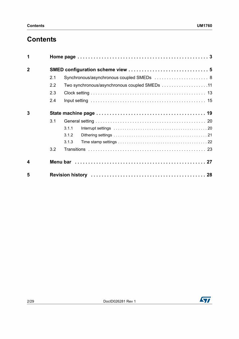
1 Home page
The initial view gives a visual overview of the STLUX architecture. The user can interact with all the elements of the home page and access more detailed views for each component.
Figure 1. SMED configurator - STLUX architecture view

Home page UM1760
4/29 DocID026281 Rev 1
The user can choose to configure:
Alternatively, it is possible to use the top menu to jump into the desired view of the SMED configurator.
Figure 2. Menu bar
The clocks: click on the image representing the SMED clocks.
The inputs: click on the image representing the SMED inputs.
The finite state machine (FSM): click on the image representing the FSM.

DocID026281 Rev 1 5/29
UM1760 SMED configuration scheme view
29
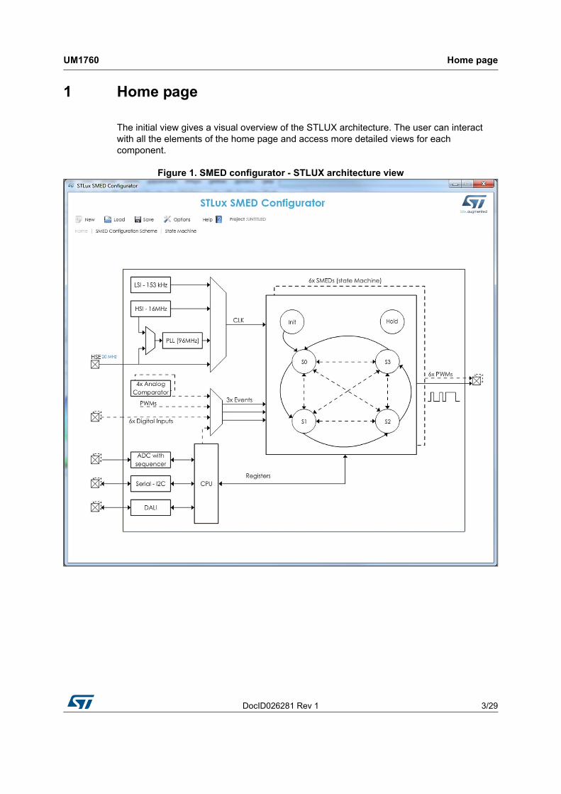
2 SMED configuration scheme view
This view allows the user to establish how to use each SMED defining its working mode.
All the possible SMED configuration schemes are:
Single SMED
Synchronous coupled SMEDs
Two synchronous coupled SMEDs
Two asynchronous coupled SMEDs
Asynchronous coupled SMEDs
Externally controlled SMED
The page shows the six SMEDs and for each of them there is a button to enable it and a button to choose the control mode (internally/externally). Each SMED, if not coupled to another, will be configured respectively in the SINGLE mode or EXTERNAL depending on whether the control button is either “Int” (internal) or “Ext” (external).
SMED configuration scheme view UM1760
6/29 DocID026281 Rev 1
Figure 3. SMED configuration view
DocID026281 Rev 1 7/29
UM1760 SMED configuration scheme view
29
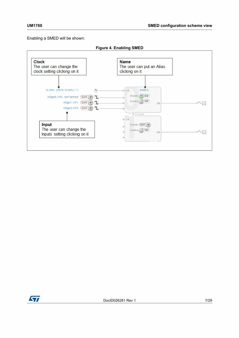
Enabling a SMED will be shown:
Figure 4. Enabling SMED
SMED configuration scheme view UM1760
8/29 DocID026281 Rev 1
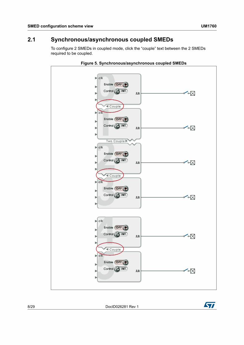
2.1 Synchronous/asynchronous coupled SMEDs
To configure 2 SMEDs in coupled mode, click the “couple” text between the 2 SMEDs required to be coupled.
Figure 5. Synchronous/asynchronous coupled SMEDs
DocID026281 Rev 1 9/29
UM1760 SMED configuration scheme view
29
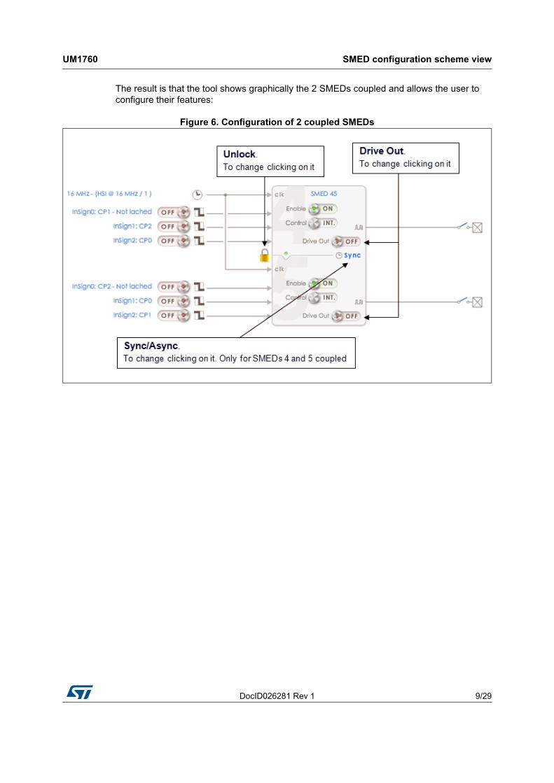
The result is that the tool shows graphically the 2 SMEDs coupled and allows the user to configure their features:
Figure 6. Configuration of 2 coupled SMEDs
SMED configuration scheme view UM1760
10/29 DocID026281 Rev 1
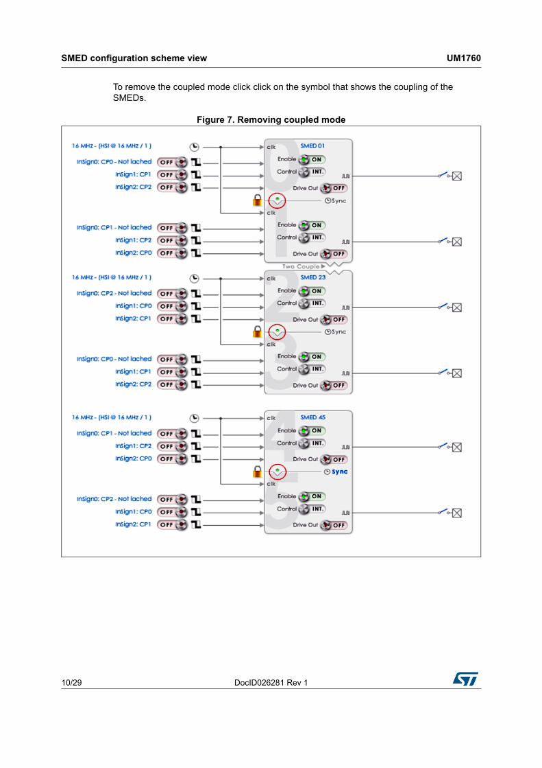
To remove the coupled mode click click on the symbol that shows the coupling of the SMEDs.
Figure 7. Removing coupled mode

DocID026281 Rev 1 11/29
UM1760 SMED configuration scheme view
29
2.2 Two synchronous/asynchronous coupled SMEDs
To configure 4 SMEDs (SMED0 - SMED 1 - SMED 2 - SMED 3) into the two coupled mode it's needed to click on the area representing this mode:
Figure 8. Configuring 4 SMEDs into two coupled mode
SMED configuration scheme view UM1760
12/29 DocID026281 Rev 1
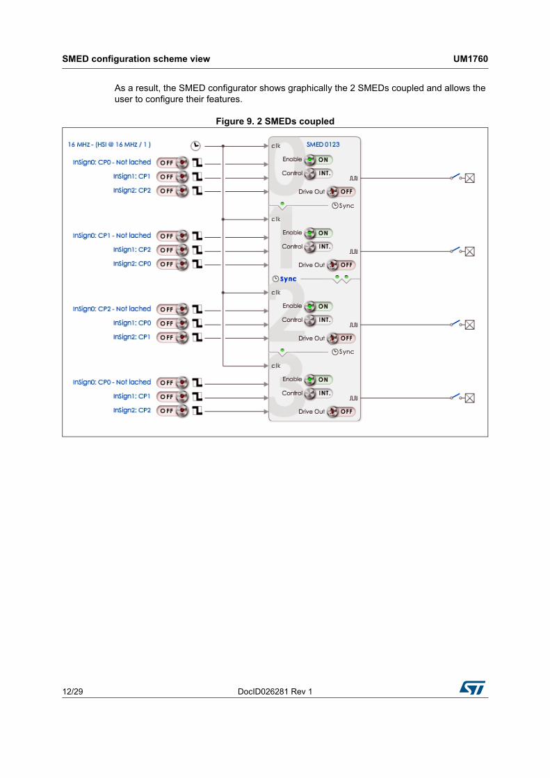
As a result, the SMED configurator shows graphically the 2 SMEDs coupled and allows the user to configure their features.
Figure 9. 2 SMEDs coupled
DocID026281 Rev 1 13/29
UM1760 SMED configuration scheme view
29
2.3 Clock setting
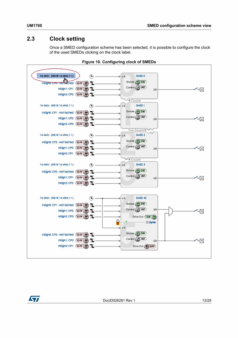
Once a SMED configuration scheme has been selected, it is possible to configure the clock of the used SMEDs clicking on the clock label.
Figure 10. Configuring clock of SMEDs
SMED configuration scheme view UM1760
14/29 DocID026281 Rev 1
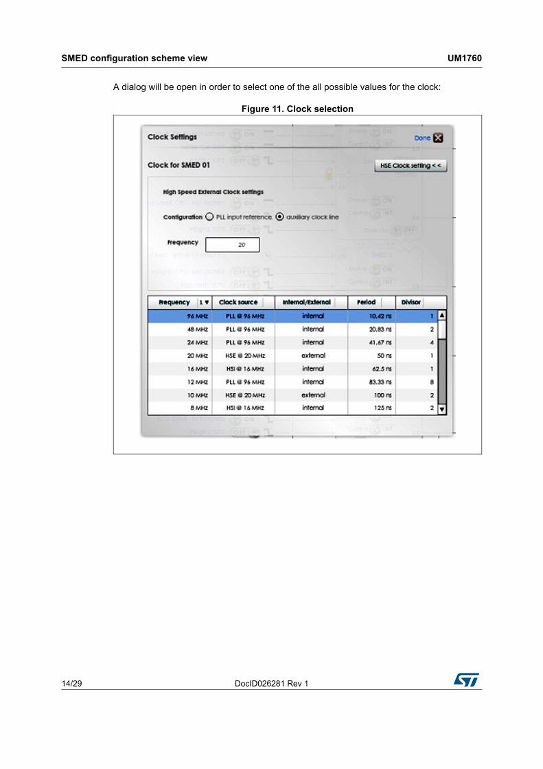
A dialog will be open in order to select one of the all possible values for the clock:
Figure 11. Clock selection
DocID026281 Rev 1 15/29
UM1760 SMED configuration scheme view
29
2.4 Input setting
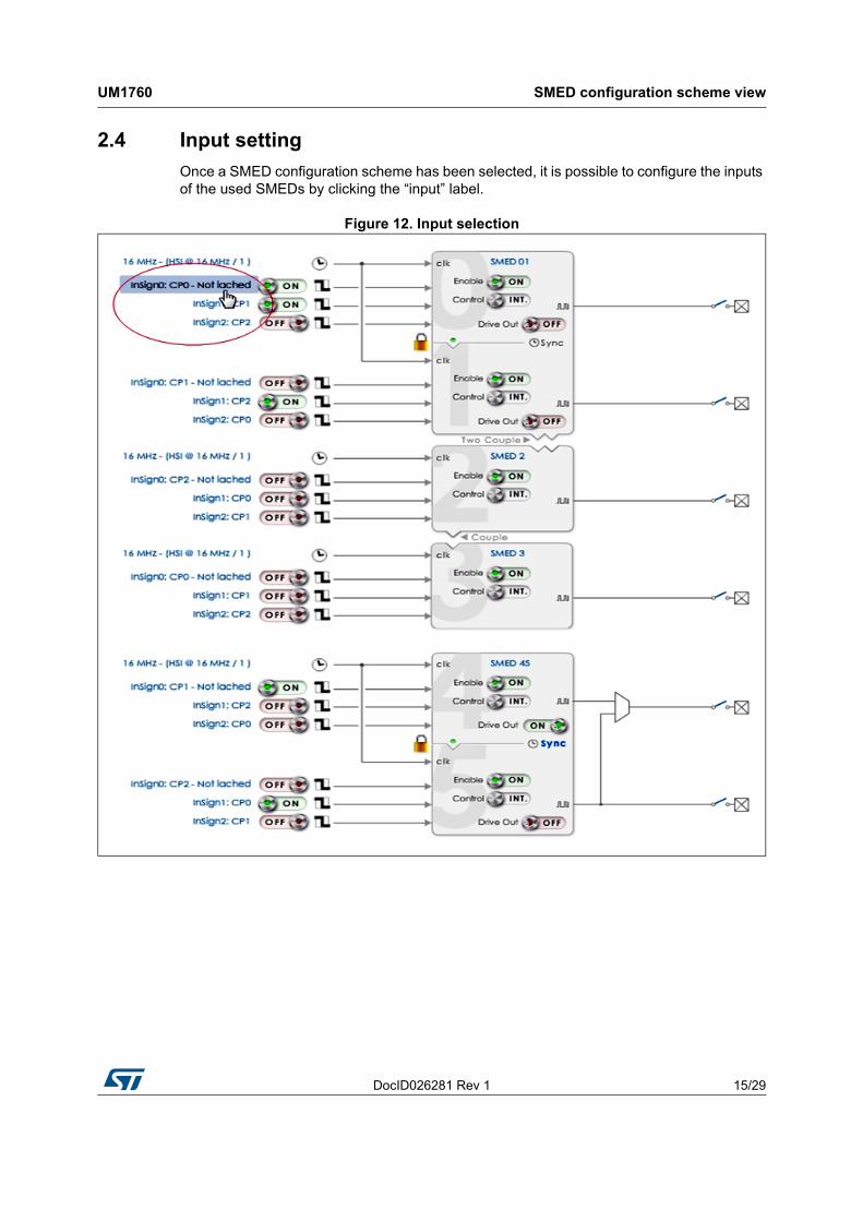
Once a SMED configuration scheme has been selected, it is possible to configure the inputs of the used SMEDs by clicking the “input” label.
Figure 12. Input selection
SMED configuration scheme view UM1760
16/29 DocID026281 Rev 1
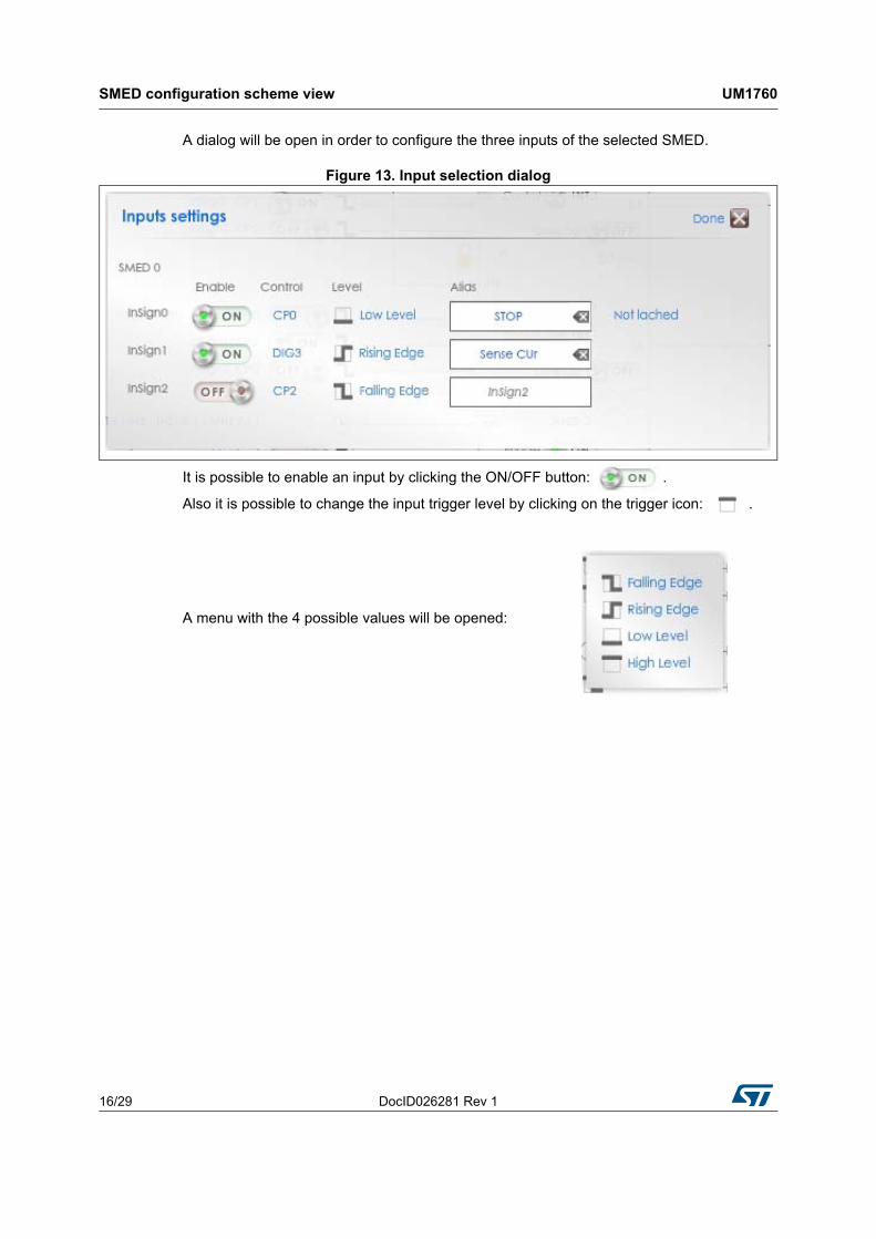
A dialog will be open in order to configure the three inputs of the selected SMED.
Figure 13. Input selection dialog
It is possible to enable an input by clicking the ON/OFF button: .
Also it is possible to change the input trigger level by clicking on the trigger icon: .
A menu with the 4 possible values will be opened:
DocID026281 Rev 1 17/29
UM1760 SMED configuration scheme view
29
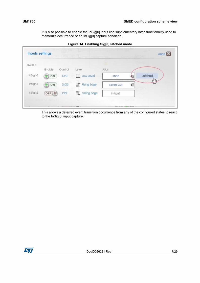
It is also possible to enable the InSig[0] input line supplementary latch functionality used to memorize occurrence of an InSig[0] capture condition.
Figure 14. Enabling Sig[0] latched mode
This allows a deferred event transition occurrence from any of the configured states to react to the InSig[0] input capture.

SMED configuration scheme view UM1760
18/29 DocID026281 Rev 1
The latched information is selectively cleared by entering any of the S0 - S3 states if the latch reset for the state is set in the correspondent SMED state machine page.
Figure 15. Latch mode as represented in the FSM
DocID026281 Rev 1 19/29
UM1760 State machine page
29
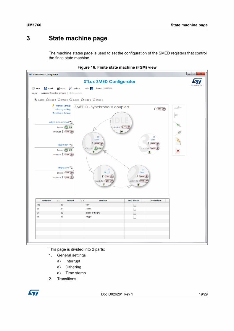
3 State machine page
The machine states page is used to set the configuration of the SMED registers that control the finite state machine.
Figure 16. Finite state machine (FSM) view
This page is divided into 2 parts:
1. General settings
a) Interrupt
a) Dithering
a) Time stamp
2. Transitions
State machine page UM1760
20/29 DocID026281 Rev 1
3.1 General setting
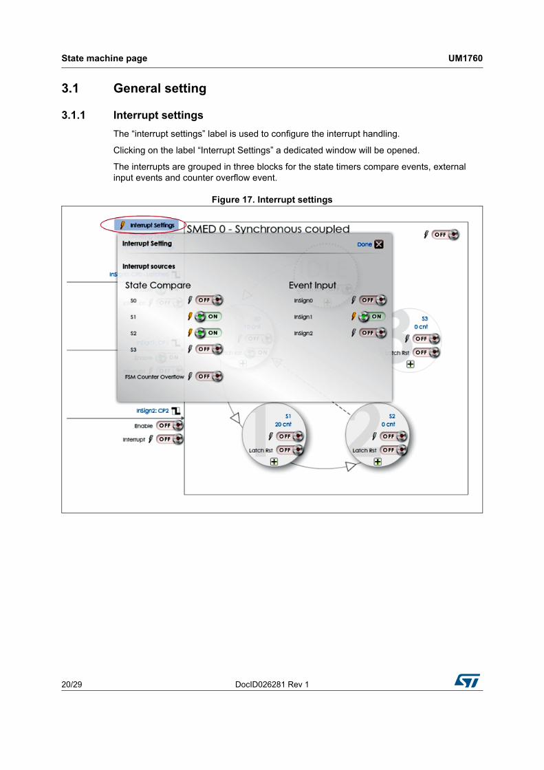
3.1.1 Interrupt settings
The “interrupt settings” label is used to configure the interrupt handling.
Clicking on the label “Interrupt Settings” a dedicated window will be opened.
The interrupts are grouped in three blocks for the state timers compare events, external input events and counter overflow event.
Figure 17. Interrupt settings
DocID026281 Rev 1 21/29
UM1760 State machine page
29
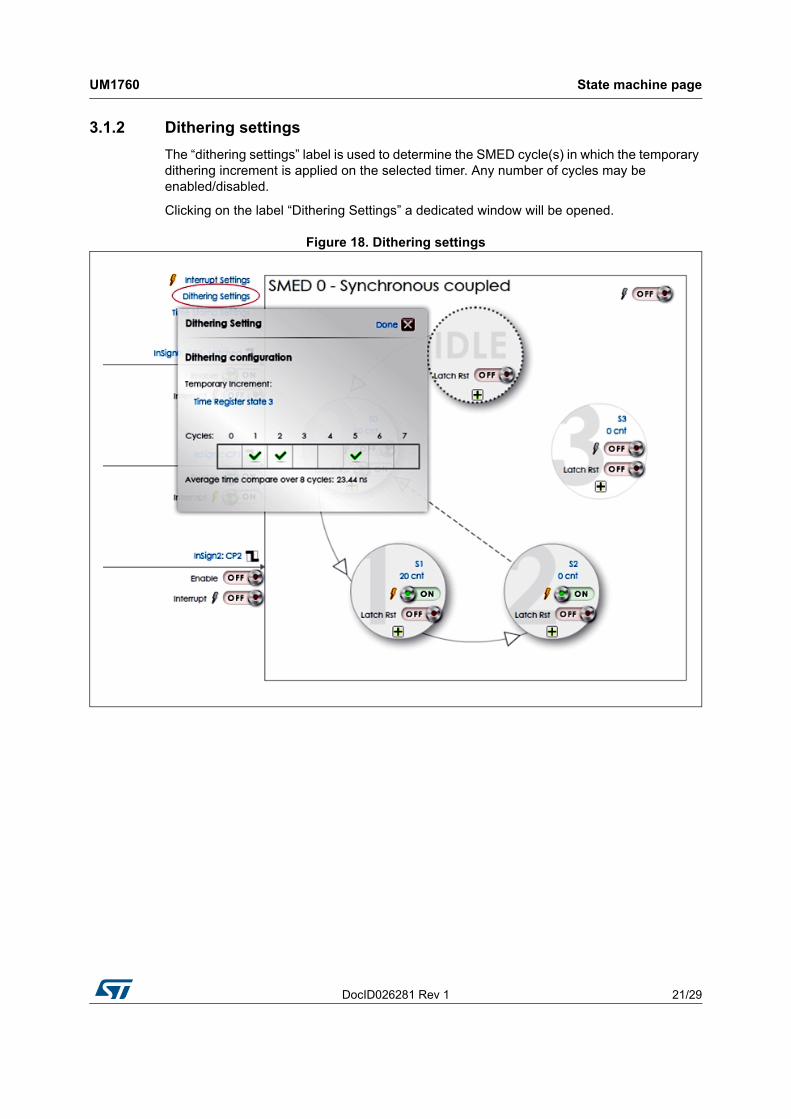
3.1.2 Dithering settings
The “dithering settings” label is used to determine the SMED cycle(s) in which the temporary dithering increment is applied on the selected timer. Any number of cycles may be enabled/disabled.
Clicking on the label “Dithering Settings” a dedicated window will be opened.
Figure 18. Dithering settings
State machine page UM1760
22/29 DocID026281 Rev 1
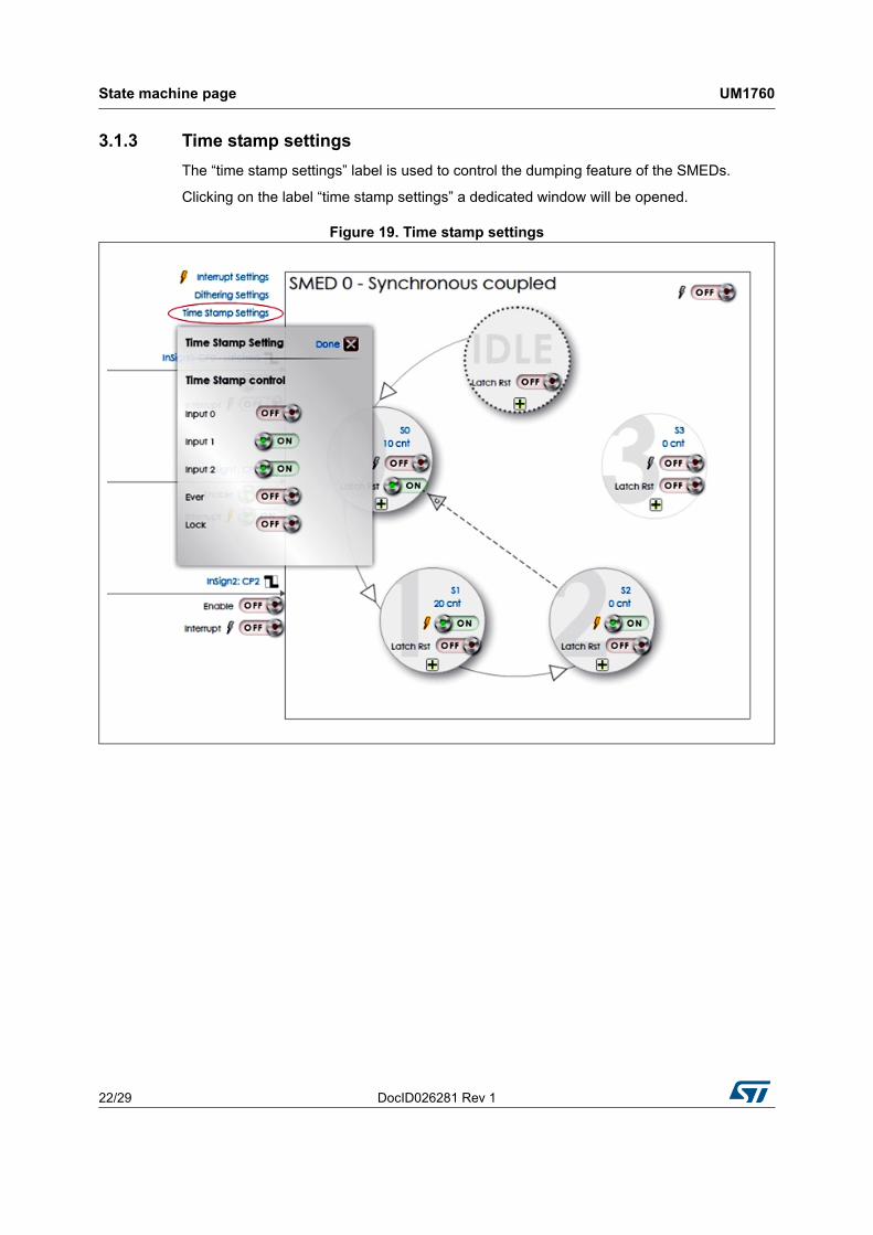
3.1.3 Time stamp settings
The “time stamp settings” label is used to control the dumping feature of the SMEDs.
Clicking on the label “time stamp settings” a dedicated window will be opened.
Figure 19. Time stamp settings
DocID026281 Rev 1 23/29
UM1760 State machine page
29
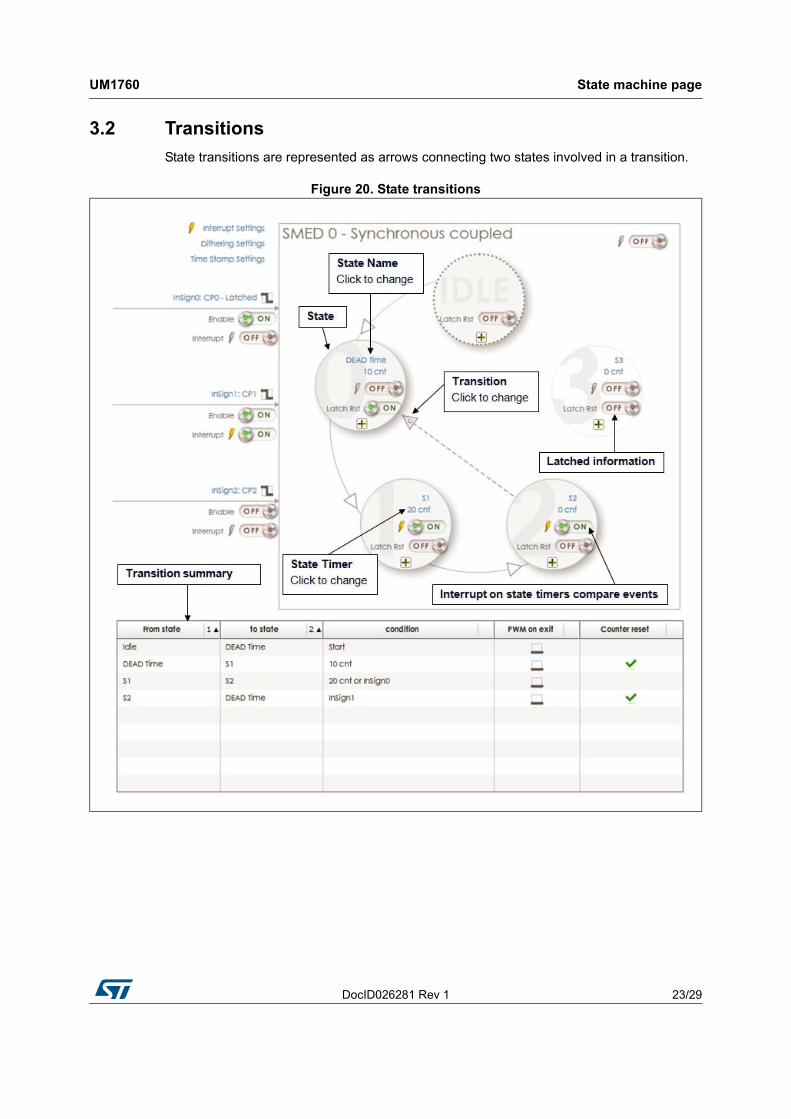
3.2 Transitions
State transitions are represented as arrows connecting two states involved in a transition.
Figure 20. State transitions
State machine page UM1760
24/29 DocID026281 Rev 1
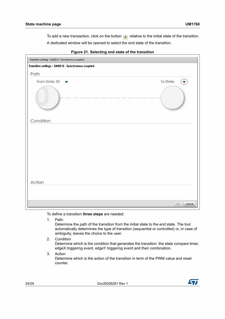
To add a new transaction, click on the button relative to the initial state of the transition.
A dedicated window will be opened to select the end state of the transition.
Figure 21. Selecting end state of the transition
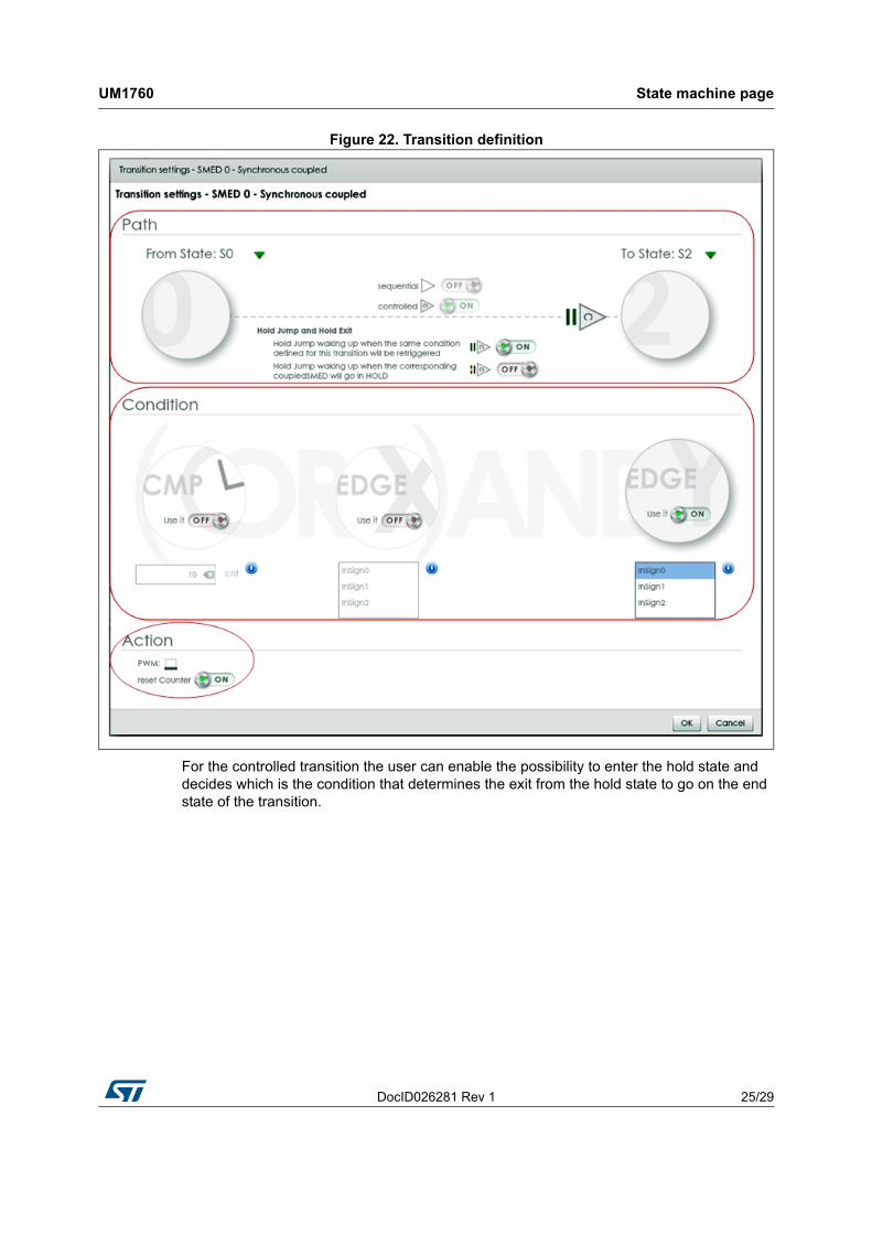
To define a transition three steps are needed:
1. Path:Determine the path of the transition from the initial state to the end state. The tool automatically determines the type of transition (sequential or controlled) or, in case of ambiguity, leaves the choice to the user.
2. ConditionDetermine which is the condition that generates the transition: the state compare timer, edgeX triggering event, edgeY triggering event and their combination.
3. ActionDetermine which is the action of the transition in term of the PWM value and reset counter.
DocID026281 Rev 1 25/29
UM1760 State machine page
29
Figure 22. Transition definition
For the controlled transition the user can enable the possibility to enter the hold state and decides which is the condition that determines the exit from the hold state to go on the end state of the transition.
State machine page UM1760
26/29 DocID026281 Rev 1
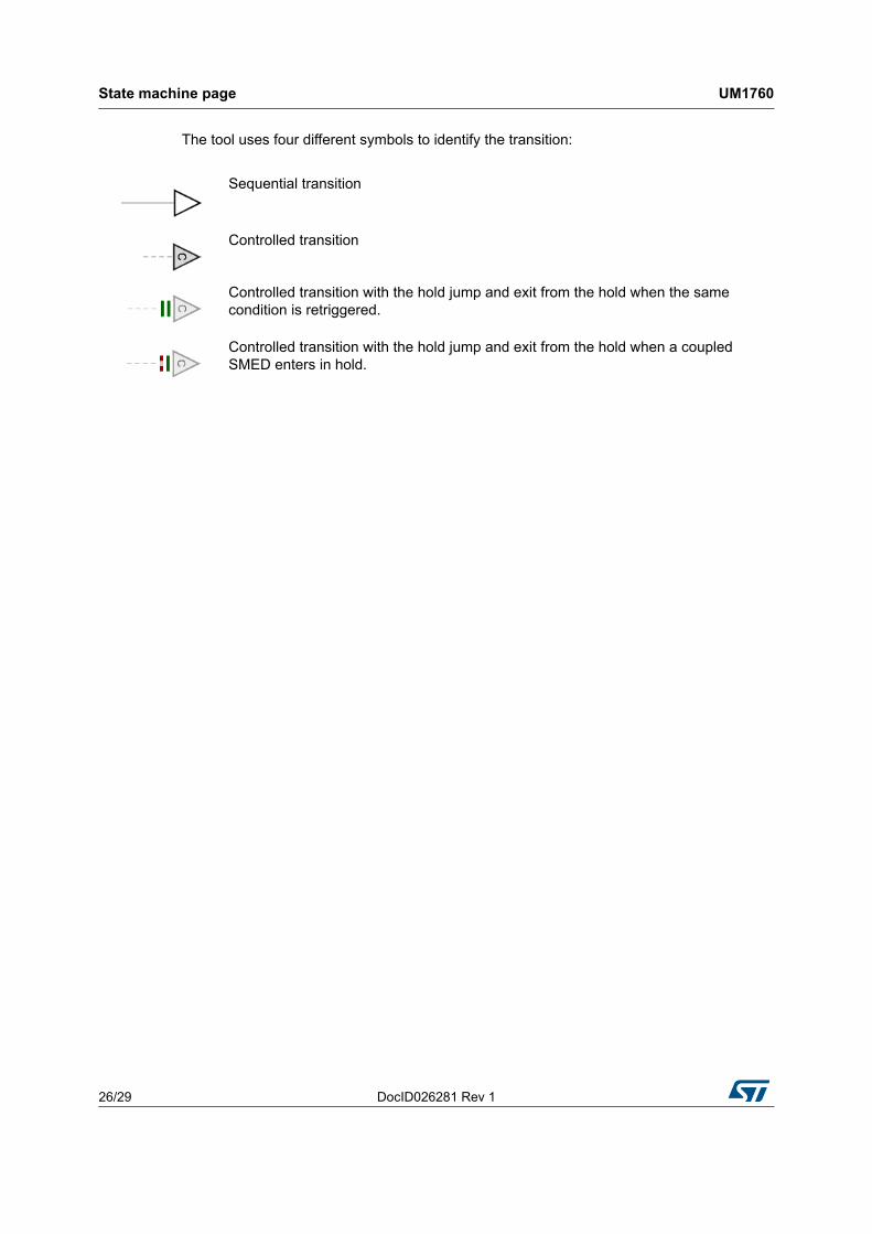
The tool uses four different symbols to identify the transition:
Sequential transition
Controlled transition
Controlled transition with the hold jump and exit from the hold when the same condition is retriggered.
Controlled transition with the hold jump and exit from the hold when a coupled SMED enters in hold.
DocID026281 Rev 1 27/29
UM1760 Menu bar
29
4 Menu bar
The menu bar contains the commands that can be used to manage the application.
The available menus are:
New
Create a new project
Load
Load existing project
Save
– Save
Save the active project
– Save As…
Save the active project with a new name
– Save C File
Save the text file, that contains the “C” source code of a simple function that initializes all the MIF and SMED registers conforming to the current configuration.
Option
Open the Option window
Help
– Help
Open this file
– Release Note
Open the Release Note document
– About
Open the About window.

Revision history UM1760
28/29 DocID026281 Rev 1
5 Revision history
Table 1. Document revision history
Date Revision Changes
14-May-2014 1 Initial release.
DocID026281 Rev 1 29/29
UM1760
29
Please Read Carefully:
Information in this document is provided solely in connection with ST products. STMicroelectronics NV and its subsidiaries (“ST”) reserve theright to make changes, corrections, modifications or improvements, to this document, and the products and services described herein at anytime, without notice.
All ST products are sold pursuant to ST’s terms and conditions of sale.
Purchasers are solely responsible for the choice, selection and use of the ST products and services described herein, and ST assumes noliability whatsoever relating to the choice, selection or use of the ST products and services described herein.
No license, express or implied, by estoppel or otherwise, to any intellectual property rights is granted under this document. If any part of thisdocument refers to any third party products or services it shall not be deemed a license grant by ST for the use of such third party productsor services, or any intellectual property contained therein or considered as a warranty covering the use in any manner whatsoever of suchthird party products or services or any intellectual property contained therein.
UNLESS OTHERWISE SET FORTH IN ST’S TERMS AND CONDITIONS OF SALE ST DISCLAIMS ANY EXPRESS OR IMPLIEDWARRANTY WITH RESPECT TO THE USE AND/OR SALE OF ST PRODUCTS INCLUDING WITHOUT LIMITATION IMPLIEDWARRANTIES OF MERCHANTABILITY, FITNESS FOR A PARTICULAR PURPOSE (AND THEIR EQUIVALENTS UNDER THE LAWSOF ANY JURISDICTION), OR INFRINGEMENT OF ANY PATENT, COPYRIGHT OR OTHER INTELLECTUAL PROPERTY RIGHT.
ST PRODUCTS ARE NOT DESIGNED OR AUTHORIZED FOR USE IN: (A) SAFETY CRITICAL APPLICATIONS SUCH AS LIFESUPPORTING, ACTIVE IMPLANTED DEVICES OR SYSTEMS WITH PRODUCT FUNCTIONAL SAFETY REQUIREMENTS; (B)AERONAUTIC APPLICATIONS; (C) AUTOMOTIVE APPLICATIONS OR ENVIRONMENTS, AND/OR (D) AEROSPACE APPLICATIONSOR ENVIRONMENTS. WHERE ST PRODUCTS ARE NOT DESIGNED FOR SUCH USE, THE PURCHASER SHALL USE PRODUCTS ATPURCHASER’S SOLE RISK, EVEN IF ST HAS BEEN INFORMED IN WRITING OF SUCH USAGE, UNLESS A PRODUCT ISEXPRESSLY DESIGNATED BY ST AS BEING INTENDED FOR “AUTOMOTIVE, AUTOMOTIVE SAFETY OR MEDICAL” INDUSTRYDOMAINS ACCORDING TO ST PRODUCT DESIGN SPECIFICATIONS. PRODUCTS FORMALLY ESCC, QML OR JAN QUALIFIED AREDEEMED SUITABLE FOR USE IN AEROSPACE BY THE CORRESPONDING GOVERNMENTAL AGENCY.
Resale of ST products with provisions different from the statements and/or technical features set forth in this document shall immediately voidany warranty granted by ST for the ST product or service described herein and shall not create or extend in any manner whatsoever, anyliability of ST.
ST and the ST logo are trademarks or registered trademarks of ST in various countries.Information in this document supersedes and replaces all information previously supplied.
The ST logo is a registered trademark of STMicroelectronics. All other names are the property of their respective owners.
© 2014 STMicroelectronics - All rights reserved
STMicroelectronics group of companies
Australia - Belgium - Brazil - Canada - China - Czech Republic - Finland - France - Germany - Hong Kong - India - Israel - Italy - Japan - Malaysia - Malta - Morocco - Philippines - Singapore - Spain - Sweden - Switzerland - United Kingdom - United States of America
www.st.com